Embed Size (px)
Citation preview

CORAL RFP Attachment 2
LLNL-PROP-636244 RELEASE NUMBER
DRAFT CORAL BUILD STATEMENT OF WORK
December 31, 2013 CORAL: Collaboration of Oak Ridge, Argonne and Livermore National Laboratories
Department of Energy
Office of Science and the National Nuclear Security Administration’s Advanced Simulation and Computing (ASC) Program
RFP No. B604142

DRAFT CORAL BUILD STATEMENT OF WORK CORAL RFP Attachment 2 December 31, 2013
- 2 -
Table of Contents
1.0 INTRODUCTION ..................................................................................................................................... - 7 -
2.0 PROGRAM OVERVIEW AND MISSION NEEDS .......................................................................................... - 8 -
2.1 OFFICE OF SCIENCE (SC) ............................................................................................................................... - 8 - 2.2 NATIONAL NUCLEAR SECURITY ADMINISTRATION (NNSA) .................................................................................. - 8 - 2.3 MISSION NEEDS ......................................................................................................................................... - 8 -
3.0 CORAL HIGH-LEVEL SYSTEM REQUIREMENTS ....................................................................................... - 10 -
3.1 DESCRIPTION OF THE CORAL SYSTEM (MR) ................................................................................................... - 10 - 3.2 HIGH LEVEL CORAL SYSTEM METRICS .......................................................................................................... - 10 - 3.3 CORAL HIGH LEVEL SOFTWARE MODEL (MR) ................................................................................................ - 11 - 3.4 CORAL HIGH LEVEL PROJECT MANAGEMENT (MR) ......................................................................................... - 12 - 3.5 EARLY ACCESS TO CORAL HARDWARE TECHNOLOGY (TR-1) ............................................................................. - 12 - 3.6 EARLY ACCESS TO CORAL SOFTWARE TECHNOLOGY (TR-1) ............................................................................... - 12 - 3.7 CORAL HARDWARE OPTIONS ..................................................................................................................... - 12 -
4.0 CORAL APPLICATION BENCHMARKS ..................................................................................................... - 14 -
4.1 BENCHMARK CATEGORIES ........................................................................................................................... - 14 - 4.2 MARQUEE AND ELECTIVE BENCHMARKS ......................................................................................................... - 16 - 4.3 BENCHMARK AVAILABILITY ......................................................................................................................... - 16 - 4.4 PERFORMANCE MEASUREMENTS (FIGURES OF MERIT) (TR-1) ............................................................................ - 16 - 4.5 BENCHMARKING PROCEDURES ..................................................................................................................... - 17 - 4.6 REPORTING GUIDELINES ............................................................................................................................. - 20 -
5.0 CORAL COMPUTE PARTITION ............................................................................................................... - 21 -
5.1 COMPUTE PARTITION HARDWARE REQUIREMENTS .......................................................................................... - 21 - 5.2 COMPUTE PARTITION SOFTWARE REQUIREMENTS ............................................................................................ - 22 -
6.0 INPUT/OUTPUT SUBSYSTEM ................................................................................................................ - 26 -
6.1 ION REQUIREMENTS ................................................................................................................................. - 26 - 6.2 BURST BUFFER REQUIREMENTS (TR-1) .......................................................................................................... - 27 -
7.0 CORAL HIGH PERFORMANCE INTERCONNECT ...................................................................................... - 29 -
7.1 HIGH PERFORMANCE INTERCONNECT HARDWARE REQUIREMENTS ...................................................................... - 29 - 7.2 COMMUNICATION/COMPUTATION OVERLAP (TR-2) ........................................................................................ - 29 - 7.3 PROGRAMMING MODELS REQUIREMENTS ...................................................................................................... - 29 - 7.4 QUALITY OF SERVICE/MESSAGE CLASSES (TR-2) ............................................................................................. - 32 -
8.0 BASE OPERATING SYSTEM, MIDDLEWARE AND SYSTEM RESOURCE MANAGEMENT ............................ - 33 -
8.1 BASE OPERATING SYSTEM REQUIREMENTS (TR-1) ........................................................................................... - 33 - 8.2 DISTRIBUTED COMPUTING MIDDLEWARE ....................................................................................................... - 33 - 8.3 SYSTEM RESOURCE MANAGEMENT (SRM) (TR-1) ........................................................................................... - 34 -

DRAFT CORAL BUILD STATEMENT OF WORK CORAL RFP Attachment 2 December 31, 2013
- 3 -
9.0 FRONT-END ENVIRONMENT ................................................................................................................ - 38 -
9.1 FRONT-END NODE (FEN) HARDWARE REQUIREMENTS ..................................................................................... - 38 - 9.2 FRONT-END ENVIRONMENT SOFTWARE REQUIREMENTS ................................................................................... - 39 -
10.0 SYSTEM MANAGEMENT AND RAS INFRASTRUCTURE ......................................................................... - 48 -
10.1 ROBUST SYSTEM MANAGEMENT FACILITY (TR-1) .......................................................................................... - 48 - 10.2 RELIABILITY, AVAILABILITY AND SERVICEABILITY (TR-1) .................................................................................. - 49 -
11.0 CORAL MAINTENANCE AND SUPPORT ............................................................................................... - 52 -
11.1 HARDWARE MAINTENANCE (TR-1) ............................................................................................................ - 52 - 11.2 SOFTWARE SUPPORT (TR-1) ..................................................................................................................... - 53 - 11.3 PROBLEM ESCALATION (TR-1) ................................................................................................................... - 54 - 11.4 ON-LINE DOCUMENTATION (TR-2) ............................................................................................................ - 54 - 11.5 ON-SITE ANALYST SUPPORT (TO-1)............................................................................................................ - 54 - 11.6 CLEARANCE REQUIREMENTS FOR CORAL SUPPORT PERSONNEL AT LLNL (TR-1) ................................................. - 54 -
12.0 CORAL PARALLEL FILE SYSTEM AND SAN (MO) ................................................................................... - 55 -
12.1 CORAL FILE SYSTEM REQUIREMENTS ......................................................................................................... - 55 - 12.2 CORAL SYSTEM AREA NETWORK (SAN) REQUIREMENTS ............................................................................... - 60 - 12.3 COMMON CFS AND SAN REQUIREMENTS .................................................................................................... - 61 -
13.0 CORAL FACILITIES REQUIREMENTS .................................................................................................... - 63 -
13.1 ANL FACILITIES OVERVIEW ....................................................................................................................... - 63 - 13.2 LLNL FACILITIES OVERVIEW ...................................................................................................................... - 64 - 13.3 ORNL FACILITIES OVERVIEW ..................................................................................................................... - 64 - 13.4 LABORATORIES FACILITIES OVERVIEW SUMMARY ........................................................................................... - 65 - 13.5 POWER & COOLING REQUIREMENTS (TR-1) ................................................................................................. - 65 - 13.6 FLOOR SPACE REQUIREMENTS (TR-1) ......................................................................................................... - 67 - 13.7 RACK HEIGHT AND WEIGHT REQUIREMENTS (TR-1) ....................................................................................... - 67 - 13.8 CABLE MANAGEMENT REQUIREMENTS (TR-1) .............................................................................................. - 67 - 13.9 PHYSICAL ACCESS REQUIREMENTS (TR-1) .................................................................................................... - 68 - 13.10 SAFETY REQUIREMENTS (TR-1) ............................................................................................................... - 68 - 13.11 SAFETY AND POWER STANDARDS (TR-1) ................................................................................................... - 68 - 13.12 RACK SEISMIC PROTECTION (TR-2) .......................................................................................................... - 68 - 13.13 SITE PREPARATION PLAN (TR-1) .............................................................................................................. - 68 -
14.0 PROJECT MANAGEMENT (TR-1) ......................................................................................................... - 69 -
14.1 BUILD SYSTEM PROTOTYPE REVIEW (TR-1) .................................................................................................. - 75 - 14.2 ACCEPTANCE REQUIREMENTS (TR-1) .......................................................................................................... - 75 -
15.0 APPENDIX A GLOSSARY ..................................................................................................................... - 77 -

DRAFT CORAL BUILD STATEMENT OF WORK CORAL RFP Attachment 2 December 31, 2013
- 4 -
This document was prepared as an account of work sponsored by an agency of the United States government. Neither the United States government nor CORAL, nor any of their employees makes any warranty, expressed or implied, or assumes any legal liability or responsibility for the accuracy, completeness, or usefulness of any information, apparatus, product, or process disclosed, or represents that its use would not infringe privately owned rights. Reference herein to any specific commercial product, process, or service by trade name, trademark, manufacturer, or otherwise does not necessarily constitute or imply its endorsement, recommendation, or favoring by the United States government or CORAL. The views and opinions of authors expressed herein do not necessarily state or reflect those of the United States government or CORAL, and shall not be used for advertising or product endorsement purposes.
This work will be performed under the auspices of the U.S. Department of Energy by Oak Ridge National Laboratory under contract DE-AC0500OR22725, Argonne National Laboratory under contract DE-AC02-06CH11357, and Lawrence Livermore National Laboratory under Contract DE-AC52-07NA27344.

DRAFT CORAL BUILD STATEMENT OF WORK CORAL RFP Attachment 2 December 31, 2013
- 5 -
Requirements Definitions
Particular sections of these technical requirements have priority designations, which are defined as follows.
(a) Mandatory Requirements designated as (MR)
Mandatory Requirements in this draft build Statement of Work (SOW) are performance features that are essential to the Laboratories’ requirements, and an Offeror must satisfactorily propose all Mandatory Requirements in order to have its proposal considered responsive.
(b) Mandatory Option Requirements designated as (MO)
Mandatory Option Requirements in this draft build SOW are features, components, performance characteristics, or upgrades whose availability as options to the Laboratories are mandatory, and an Offeror must satisfactorily propose all Mandatory Option Requirements in order to have its proposal considered responsive. The Laboratories may or may not elect to include such options in the resulting subcontract(s). Therefore, each Mandatory Option Requirement shall appear as a separately identifiable item in an Offeror’s proposal. MOs are alternative features, components, performance characteristics or system sizes that may be considered for technical and/or budgetary reasons.
(c) Technical Option Requirements designated as (TO-1), (TO-2), or (TO-3)
Technical Option Requirements in this draft build SOW are features, components, performance characteristics, or upgrades that are important to the Laboratories, but which will not result in a nonresponsive determination if omitted from a proposal. Technical Options add value to a proposal. Technical Options are prioritized by dash number. TO-1 is most desirable to the Laboratories, while TO-2 is more desirable than TO-3. Technical Option Requirement responses will be considered as part of the proposal evaluation process; however, the Laboratories may or may not elect to include Technical Option Requirements in the resulting subcontract(s). Each proposed Technical Option Requirement should appear as a separately identifiable item in an Offeror’s proposal response. Technical Option Requirements may also affect the Laboratories’ perspective of the ideal CORAL system(s), depending on future budget considerations.
(d) Target Requirements designated as (TR-1), (TR-2), or (TR-3).
Target Requirements in this draft build SOW are features, components, performance characteristics, or other properties that are important to the Laboratories, but will not result in a nonresponsive determination if omitted from a proposal. Target Requirements add value to a proposal. Target Requirements are prioritized by dash number. The aggregate of MRs and TR-1s form a baseline system. TR-2s are goals that boost a baseline system, taken together as an aggregate of MRs, TR-1s and TR-2s, into the moderately useful system. TR-3s are stretch goals that boost a moderately useful system, taken together as an aggregate of MRs, TR-1s, TR-2s and TR-3s, into the highly useful system. Therefore, the ideal CORAL system will meet or exceed all MRs, TR-1s, TR-2s and TR-3s. Target Requirement responses will be considered as part of the proposal evaluation process.
(e) Terminology.

DRAFT CORAL BUILD STATEMENT OF WORK CORAL RFP Attachment 2 December 31, 2013
- 6 -
Verb forms such as “will”, “will provide”, or “will include” are generally used throughout the SOW to describe desired outcomes and not mandatory requirements.
“offeror” generally means a supplier / vendor / company that submits a proposal in response to this RFP.
“selected offeror” or “successful offeror” or “subcontractor” generally means a supplier / vendor / company that submits a proposal in response to this RFP, and is selected for award.
“lower-tier subcontractor” generally means a supplier / vendor / company that provides goods and / or services to the subcontractor.

DRAFT CORAL BUILD STATEMENT OF WORK CORAL RFP Attachment 2 December 31, 2013
- 7 -
1.0 Introduction This document contains the collective technical requirements of CORAL, a Collaboration of Oak Ridge National Laboratory (ORNL), Argonne National Laboratory (ANL) and Lawrence Livermore National Laboratory (LLNL), hereafter referred to as the Laboratories, for three pre-exascale High Performance Computing (HPC) systems to be delivered in the 2017 timeframe. These systems are required to meet the mission needs of the Advanced Scientific Computing Research (ASCR) Program within the Department of Energy’s Office of Science (SC) and the Advanced Simulation and Computing (ASC) Program within the National Nuclear Security Administration (NNSA). The Laboratories intend to choose two different system architectures and procure a total of three systems, with ANL and ORNL procuring unique architectures and LLNL procuring one of the two architectures. Related information is provided in the Proposal Preparation and Proposal Evaluation Instructions (PEPPI).
This draft build SOW describes specific technical requirements (refer to the preceding Requirements Definitions Section for particular technical requirements definitions) related to both the hardware and software capabilities of the desired system(s) as well as application requirements.
The Laboratories anticipate the following schedule for the DOE 2017 system acquisitions based on calendar years:
4Q 2012 ORNL released the CORAL RFI to gather information about potential systems and related Non-Recurring Engineering (NRE) for the next acquisitions at ANL, LLNL, and ORNL;
2Q 2013 Vendor Conference discussed draft CORAL Procurement Framework;
4Q 2013 LLNL releases final CORAL RFP;
1Q 2014 proposal responses are due and will be evaluated by the CORAL evaluation team;
1Q 2014 two winning primes will be chosen; one to deliver a system to ORNL and the other to ANL. LLNL will choose one of the winning primes to deliver a system to its facility;
2Q 2014 two NRE contracts awarded by LLNS – one to each prime;
2Q-3Q 2014 three separate acquisition subcontracts awarded, one by each Laboratory;
3Q-4Q 2017 pre-exascale systems delivered to ORNL, ANL, and LLNL.
The Laboratories reserve their right to revise any or all of the points reflected in the above schedule based upon the Laboratories’ and / or DOE’s needs.

DRAFT CORAL BUILD STATEMENT OF WORK CORAL RFP Attachment 2 December 31, 2013
- 8 -
2.0 Program Overview and Mission Needs 2.1 Office of Science (SC)
The SC is the lead Federal agency supporting fundamental scientific research for energy and the nation’s largest supporter of basic research in the physical sciences. The SC portfolio has two principal thrusts: direct support of scientific research and direct support of the development, construction, and operation of unique, open-access scientific user facilities. These activities have wide-reaching impact. SC supports research in all 50 States and the District of Columbia, at DOE laboratories, and at more than 300 universities and institutions of higher learning nationwide. The SC user facilities provide the Nation’s researchers with state-of-the-art capabilities that are unmatched anywhere in the world.
Within SC, the mission of the Advanced Scientific Computing Research (ASCR) program is to discover, to develop, and to deploy computational and networking capabilities to analyze, to model, to simulate, and to predict complex phenomena important to the DOE. A particular challenge of this program is fulfilling the science potential of emerging computing systems and other novel computing architectures, which will require numerous significant modifications to today's tools and techniques to deliver on the promise of exascale science.
2.2 National Nuclear Security Administration (NNSA) The NNSA, an agency within the Department of Energy, is responsible for the management and security of the nation’s nuclear weapons, nuclear nonproliferation, and naval reactor programs. The NNSA Strategic Plan supports the Presidential declaration that the United States will maintain a “safe, secure, and effective nuclear arsenal.” The Plan includes ongoing commitments:
• to understand the condition of the nuclear stockpile; and • to extend the life of U.S. nuclear warheads.
The NNSA’s Advanced Simulation and Computing (ASC) Program provides the computational resources that are essential to enable nuclear weapon scientists to fulfill stockpile stewardship requirements through simulation in lieu of underground testing. Modern simulations on powerful computing systems are key to supporting this national security mission.
As the stockpile moves further from the nuclear test base, through aging of stockpile systems or modifications involving system refurbishment, reuse, or replacement, the realism and accuracy of ASC simulations must increase significantly through development and use of improved physics models and solution methods, which will require orders of magnitude greater computational resources than are currently available.
2.3 Mission Needs Scientific computation has come into its own as a mature technology in all fields of science. Never before have we accurately been able to anticipate, to analyze, and to plan for complex events that have not occurred—from the operation of a reactor running at 100 million degrees to the changing climate a century from now. Combined with the more traditional approaches of theory and experiment, it provides a profound tool for insight and solution as we look at complex systems containing billions of components. Nevertheless, scientific computation cannot yet do all that we would like. Much of its potential remains untapped—in areas such as materials science, earth science, energy assurance, fundamental science, biology and medicine, engineering design, and national security—because the

DRAFT CORAL BUILD STATEMENT OF WORK CORAL RFP Attachment 2 December 31, 2013
- 9 -
scientific challenges are too enormous and complex for the computational resources at hand. Many of these challenges have immediate and global importance.
These challenges can be overcome by a revolution in computing that promises real advancement at a greatly accelerated pace. Planned pre-exascale systems (capable of 1017 floating point operations per second) in the next four years provide an unprecedented opportunity to attack these global challenges through modeling and simulation.
DOE’s SC and NNSA have several critical mission deliverables, including annual stockpile certification and safety assurance for NNSA and future energy generation technologies for SC. Computer simulations play a key role in meeting these critical mission needs. Data movement in the scientific codes is becoming a critical bottleneck in their performance. Thus memory hierarchy and its latencies and bandwidths between all its levels are expected to be the most important system characteristic for effective pre-exascale systems.
Data intensive workloads are of increasing importance to SC and are becoming an integral part of many traditional scientific computational science domains including cosmology, engineering, combustion, and astrophysics. The pre-exascale systems will need data centric capabilities to meet the mission needs in these science domains.

DRAFT CORAL BUILD STATEMENT OF WORK CORAL RFP Attachment 2 December 31, 2013
- 10 -
3.0 CORAL High-Level System Requirements 3.1 Description of the CORAL System (MR)
The Offeror shall provide a concise description of its proposed CORAL system architecture, including all major system components plus any unique features that should be considered in the design. The description shall include: • An overall system architectural diagram showing all node types and their quantity,
interconnect(s), burst buffer and SAN. The diagram will also show the latencies and bandwidths of data pathways between components.
• An architectural diagram of each node type showing all elements of the node along with the latencies and bandwidths to move data between the node elements.
The Offeror shall describe how the proposed system fits into its long-term product roadmap and how the technologies, architecture, and programming are on a path to exascale.
3.2 High Level CORAL System Metrics A design that meets or exceeds all metrics outlined in this section is strongly desired.
3.2.1 CORAL System Performance (TR-1) CORAL places a particularly high importance on system performance. The Offeror will provide projected performance results for the proposed system for the four TR-1 Scalable Science Benchmarks and the four TR-1 Throughput Benchmarks. The target (speedup) performance requirements will be at least Sscalable= 4.0 and Sthroughput= 6.0, respectively, where Sscalable and Sthroughput are defined in Section 4. The Offeror will also provide the performance results of the three TR-1 Data-Centric benchmarks and the five TR-1 Skeleton Benchmarks. The Offeror will explain the methodology used to determine all projected results.
3.2.2 CORAL System Extended Performance (TR-2) The CORAL benchmarks provide additional TR-2 applications for Throughput and Skeleton applications. The Offeror may project the performance of these benchmarks on the proposed CORAL system. The Offeror will explain the methodology used to determine all projected results.
3.2.3 CORAL System Micro Benchmarks Performance (TR-3) The CORAL benchmarks provide a set of Micro Benchmarks that are intended to aid the Offeror in any simulations or emulations used in predicting the performance of the CORAL system. The Offeror may project the performance of these benchmarks on the proposed CORAL system. The Offeror will explain the methodology used to determine all projected results.
3.2.4 CORAL System Peak (TR-1) The CORAL baseline system performance will be at least 100.0 petaFLOP/s (100.0x10¹⁵ double-precision floating point operations per second).
3.2.5 Total Memory (TR-1) The system will have an aggregate of at least 4PB of memory available for direct application use. This total can consist of any memory directly addressable from a user program, including DRAM, NVRAM, and smart memory. Non-Uniform Memory Access (NUMA) designs are acceptable, but not necessarily desired. The memory counted toward the aggregate requirement

DRAFT CORAL BUILD STATEMENT OF WORK CORAL RFP Attachment 2 December 31, 2013
- 11 -
will not include cache memory, or memory dedicated to system software usage (e.g., burst buffers).
The Offeror may choose how to balance the system between different types of memory for optimal price–performance. The memory configuration of the proposed system will be the memory configuration used to achieve the TR-1 benchmark results reported in the Offeror’s proposal. CORAL will place high value on solutions that maximize the ratio of "fast and close" memory to "far and slow" memory. The CORAL application benchmarks provide a guide to determine an appropriate balance.
3.2.6 Memory per MPI Task (TR-2) A minimum of 1GB per MPI task will be provided, with 2 GB per MPI task preferred, counting all directly addressable memory types available, e.g., DRAM, NVRAM, and smart memory. For systems that provide less than 1GB main memory-per-core and thus cannot run MPI-everywhere, threading (for example, via OpenMP/OpenACC/CUDA/other) shall be used to obtain additional concurrency.
3.2.7 Maximum Power Consumption (TR-1) The maximum power consumed by the CORAL system and all its peripheral systems, including the proposed storage system, will not exceed 20MW. This limit includes all the equipment provided by the proposal The power consumption of the main system, its peripherals, and the storage system will be broken out individually in the proposal.
3.2.8 System Resilience (TR-1) The Mean Time Between Application Failure due to a system fault requiring user or administrator action will be at least 144 hours (6.0 days). The failure rates of individual components can be much higher as long as the overall system adapts, and any impacted jobs or services are restarted without user or administrator action.
This resilience requirement is designed to maximize the different ways a system could be designed and still perceived to be resilient. At one extreme, a system could be proposed with highly reliable (and possibly redundant) components to the point that a system fault that causes an application failure is only expected every 144 hours. At the other extreme, a system could be proposed with very unreliable components and the system software would have to compensate by being very reliable and adaptable so that no user or administrator action is required for jobs to continue to run. There are many design choices between these extremes that the Offeror is free to consider.
Applications that fail must be restarted. If they have no user checkpointing, they can be restarted from the beginning. If the application uses services that have been affected by a system fault, these services will be automatically restored so that the application can continue to progress.
3.2.9 Application Reliability Overhead (TR-1) An application with user check-pointing, using at least 90% of the CNs, will complete with correct results without human intervention with less than 50% overhead from restarts due to system faults.
3.3 CORAL High Level Software Model (MR) Offeror shall include a high-level software architecture diagram. This diagram shall show all major software elements. Offeror shall also describe the expected licensing strategy for each. The CORAL

DRAFT CORAL BUILD STATEMENT OF WORK CORAL RFP Attachment 2 December 31, 2013
- 12 -
software model and resulting requirements shall be described from the perspective of a highly scalable system consisting of compute nodes (CNs) numbering in the range of tens to hundreds of thousands, and sufficient I/O nodes (IONs) to manage file I/O to storage subsystems, and a Front End Environment (FEE) of sufficient capability to provide access, system management, and programming environment to a system with those CNs and IONs. The combination of CN and ION shall also provide Linux-like capability and compatibility. The Offeror shall describe how the system software is able to track early signs of system faults, to manage power dynamically, to collect power and energy statistics, and to report accurate and timely information about the hardware, software, and applications from all components in the system. The Offeror is only required to supply one OS per node type, but the architecture should not preclude the booting of different node OSs, allowing system software developers to run jobs for data-centric, SPMD, or dynamic multithreaded programming models.
3.3.1 Open Source Software (TR-1) The Laboratories strongly prefer that all offered software components are Open Source.
3.4 CORAL High Level Project Management (MR) The Offeror’s proposal shall include the following:
• Overview of collaboration plan and discussion of any requirements that the Offeror has for CORAL in the management of the project.
• Preliminary Risk Management Plan that describes any aspects or issues that the Offeror considers to be major risks for the system, including management of lower-tier subcontractors, and planned or proposed management and mitigations for those risks.
• Discussion of delivery schedules and various options including how Offeror would manage the tactical overlap of multiple large system deliveries and deployments in a similar time frame.
• Discussion of the approach to the installation and deployment of the system, e.g., personnel and communications, factory staging, onsite staging, installation, integration, testing, and bring-up.
• Discussion of Offeror’s general approach for software licensing, e.g., range of licenses and criteria for selection from that range of licenses for a particular package.
• Discussion of Offeror’s quality assurance and factory test plans.
3.5 Early Access to CORAL Hardware Technology (TR-1) The Offeror will propose mechanisms to provide the Laboratories with early access to hardware technology for hardware and software testing prior to inserting the technology into the CORAL system. Small additional early access systems are encouraged, particularly if they are sited at the Laboratories.
3.6 Early Access to CORAL Software Technology (TR-1) The Offeror will propose mechanisms to provide the Laboratories with early access to software technology and to test software releases and patches before installation on the CORAL system.
3.7 CORAL Hardware Options Offeror will propose the following separately priced technical option requirements (Sections 3.7.1, 3.7.2, 3.7.3, 3.7.4, and 3.7.6) using whatever is the natural unit for the proposed architecture design as determined by the Offeror. For example, for system size it may be number of racks, peak PF, number

DRAFT CORAL BUILD STATEMENT OF WORK CORAL RFP Attachment 2 December 31, 2013
- 13 -
of blades, etc. If the proposed design has no option to scale one or more of these features, it is sufficient to simply state this in the proposal response. Offeror shall propose the following separately priced mandatory option (Section 3.7.5). In addition to the hardware options below, the Offeror shall also propose a Storage Area Network (SAN) and parallel file system solution for CORAL. The requirements for that solution are presented in Section 12.0.
3.7.1 Scale the System Size (TO-1) The Offeror will describe and separately price options for scaling the overall CORAL system up or down as different sites may desire different size systems.
3.7.2 Scale the System Memory (TO-1) The Offeror will describe and separately price options for configuring the CORAL system memory (and different memory type options such as NVRAM) as different sites may desire different configurations.
3.7.3 Scale the System Interconnect (TO-1) The Offeror will describe and separately price options for configuring the high performance interconnect as different sites may prefer cost savings provided by reducing bandwidth or network connectivity.
3.7.4 Scale the System I/O (TO-1) The Offeror will describe and separately price options for scaling the CORAL system I/O as different sites may desire different amounts.
3.7.5 CORAL-Scalable Unit System (MO) The Offeror shall propose, as a separately priced option, a CORAL system configuration called CORAL-SU, that consists of the minimum deployable system. CORAL partners may exercise this option for their respective sites. This option shall include a minimal front-end environment as well as I/O subsystem in addition to a smallest usable compute partition. Options and costs for scaling the CORAL-SU up to larger configurations shall be provided.
3.7.6 Options for Mid-Life Upgrades (TO-1) The Offeror will describe and separately price any options for upgrading the proposed CORAL system over its five year lifetime.

DRAFT CORAL BUILD STATEMENT OF WORK CORAL RFP Attachment 2 December 31, 2013
- 14 -
4.0 CORAL Application Benchmarks The past 15-20 years of computing have provided an almost unprecedented stability in high-level system architectures and parallel programming models, with the MPI, OpenMP, C++, and Fortran standards paving the way for performance portable code. Combined with the application trends toward more coupled physics, predictive capabilities, sophisticated data management, object oriented programming, and massive scalability – the DOE applications that CORAL systems will run each represents tens or hundreds of person-years of effort, and thousands of person-years in aggregate. Thus, there is a keen interest in protecting the Laboratories’ investment in the DOE application base by procuring systems that allow today’s workhorse application codes to continue to run without radical overhauls. The Laboratories’ target codes are highly scalable with MPI, and many utilize OpenMP threading (or are planning to do so in the timeframe of this procurement) and/or the use of GPGPU accelerators to take advantage of fine-grained on-node concurrency.
It is expected that disruptive changes will be required of the applications for them to exploit performance features of the CORAL systems. Both SC and NNSA applications seek solutions that minimize disruptive changes to software that are not part of a standard programming model likely to be available on multiple future acquisitions, while recognizing the need that the existing software base must continue to evolve.
The CORAL procurement is a major leap in capability that is a stepping stone toward the goal of an exascale system. The preferred solution will be one that provides innovative solutions for hardware with a demonstrable path toward performance portability using a software stack and tools that will ease the transition without sacrificing our goals for continued delivery of top predictive science and stockpile stewardship mission deliverables.
The CORAL benchmarks have thus been carefully chosen and developed to represent the broad range of applications expected to dominate the science and mission deliverables on the CORAL systems.
4.1 Benchmark Categories The benchmarks have been divided into five broad categories representing the envisioned system workloads and targeted benchmarks to allow specific insight into features of the proposed system.
Scalable Science Benchmarks are full applications that are expected to scale to a large fraction of the CORAL system and that are typically single physics applications designed to push the boundaries of human understanding of science in areas such as material science and combustion. Discovery science is a core mission of SC and NNSA, and the benchmarks chosen represent important applications that will keep the DOE on the forefront of pioneering breakthroughs. Moreover, it is the primary mission of the SC Leadership Computing Facilities to enable the most ambitious examples of capability computing at any given moment, where scalability is of singular importance.
Throughput Benchmarks represent particular subsets of applications that are expected to be used as part of the everyday workload of science applications at all CORAL sites. In particular, Uncertainty Quantification (UQ) is a driving mission need for the ASC program, where the CORAL system at LLNL is expected to run large ensembles of 10’s or 100’s of related calculations, with a priority on minimizing the ensemble’s overall throughput time. Each individual run in a UQ ensemble will require moderate scaling, while greatly reducing the overall time to completion for the ensemble study.
CORAL Benchmarks

DRAFT CORAL BUILD STATEMENT OF WORK CORAL RFP Attachment 2 December 31, 2013
- 15 -
Parallelism Language
Priority Level Code
Lines of Code MPI
OpenMP/pthreads F Py C C++ Description
Scalable Science Benchmarks TR-1 LSMS 200,000 X X X X Floating point performance, point-to-point communication scalingTR-1 QBOX 47,000
X X X Quantum molecular dynamics. Memory bandwidth, high floating point intensity, collectives (alltoallv, allreduce, bcast)
TR-1 HACC 35,000 X X X Compute intensity, random memory access, all to all communicationTR-1 NEKbone 48,000 X X X Compute intensity, small messages, allreduce
Throughput Benchmarks TR-1 CAM-SE 150,000 X X X X Memory bandwidth, strong scaling, MPI latency TR-1 UMT 51,000 X X X X X X Single physics package code. Unstructured-mesh deterministic radiation transport.
Memory bandwidth, compute intensity, large messages, Python TR-1 AMG2013 75,000 X X X Algebraic multi-grid linear system solver for unstructured mesh physics packagesTR-1 MCB 13,000 X X X Monte Carlo transport. Non-floating point intensive, branching, load balancingTR-2 QMCPACK 200,000 X X X X Memory bandwidth, thread efficiency, compilers TR-2 NAMD 180,000 X X X Classical molecular dynamics. Compute intensity, random memory access, small
messages, all-to-all communications TR-2 LULESH 5,000 X X X Shock hydrodynamics for unstructured meshes. Fine-grained loop level threadingTR-2 SNAP 3,000 X X X Deterministic radiation transport for structured meshes TR-2 miniFE 50,000 X X X Finite element code
Data-Centric Benchmarks TR-1 Graph500 X Scalable breadth-first seach of a large undirected graph TR-1 Integer Sort 2,000 X X X Parallel integer sortTR-1 Hash X X Parallel hash benchmarkTR-2 SPECint2006
“peak” X X X CPU integer processor benchmark ; report peak results or estimates
Skeleton Benchmarks TR-1 CLOMP X X Measure OpenMP overheads and other performance impacts due to threadingTR-1 IOR 4,000 X X Interleaved or random I/O benchmark. Used for testing the performance of parallel
file systems and burst buffers using various interfaces and access patterns TR-1 CORAL MPI
Benchmarks 1,000 X X Subsystem functionality and performance tests. Collection of independent MPI
benchmarks to measure various aspects of MPI performance including interconnect messaging rate, latency, aggregate bandwidth, and collective latencies
TR-1 Memory Benchmarks
1,500 X X Memory subsystem functionality and performance tests. Collection of STREAMS and STRIDE memory benchmarks to measure the memory subsystem under a variety of memory access patterns
TR-1 LCALS 5,000 X X Single node. Application loops to test the performance of SIMD vectorization TR-2 Pynamic 12,000 X X X Subsystem functionality and performance test. Dummy application that closely
models the footprint of an important Python-based multi-physics ASC code TR-2 HACC IO 2,000 X X Application centric I/O benchmark testsTR-2 FTQ 1,000 X Fixed Time Quantum test. Measures operating system noise TR-2 XSBench (mini
OpenMC) 1,000 X X Monte Carlo neutron transport. Stresses system through memory capacity
(including potential NVRAM), random memory access, memory latency, threading, and memory contention
TR-2 MiniMADNESS 10,000 X X X Vector FPU, threading, active-messages
Micro Benchmarks TR-3 NEKbonemk 2,000 X Single node. NEKbone micro-kernel and SIMD compiler challengeTR-3 HACCmk 250 X X Single core optimization and SIMD compiler challenge, compute intensityTR-3 UMTmk 550 X Single node UMT micro-kernelTR-3 AMGmk 1,800 X Three compute intensive kernels from AMGTR-3 MILCmk 5,000 X X Compute intensity and memory performanceTR-3 GFMCmk 150 X X Random memory access, single node
Data Centric Benchmarks reproduce the data intensive patterns found in user applications and are useful for targeted investigation of integer operations, instruction throughput, and indirect addressing
Table 4-1: CORAL Benchmarks

DRAFT CORAL BUILD STATEMENT OF WORK CORAL RFP Attachment 2 December 31, 2013
- 16 -
capabilities, among other things. The three TR-1 Data benchmarks are: Graph 500, parallel integer sort, and parallel node level hash benchmark. There is also a TR-2 Data Centric benchmark –SPECINT2006. The Offeror will report raw values for the unmodified benchmarks. In addition, the Offeror is encouraged to optimize the Data benchmarks using any reimplementation that brings out the node level capabilities of the proposed system and report these results as well.
Skeleton Benchmarks reproduce the memory or communication patterns of a physics application or package, and make little or no attempt to investigate numerical performance. They are useful for targeted investigations such as network performance characteristics at large scale, memory access patterns, thread overheads, bus transfer overheads, system software requirements, I/O patterns, and new programming models.
Micro Benchmarks are small code fragments extracted from either science or throughput benchmarks that represent expensive compute portions of those applications. They are useful for testing programming methods and performance at the node level, and do not involve network communication (MPI). Their small size makes them ideal for early evaluations and explorations on hardware emulators and simulators.
In general, the Scalable Science Benchmarks are full applications, and thus large in terms of lines-of-code. However, the CORAL team will ensure that the portion of the application that is exercised with the benchmark test cases is minimized and well-documented.
4.2 Marquee and Elective Benchmarks Collectively, the set of TR-1 benchmarks will be referred to as the Marquee Benchmarks. TR-2 and TR-3 benchmarks will be referred to as the Elective Benchmarks. Each of the Science, Throughput, and Skeleton benchmark categories contain both Marquee and Elective benchmarks. The Micro Benchmarks are all TR-3, and are provided primarily as a convenience to the Offeror.
Although all benchmark results are important and will be carefully analyzed during proposal evaluation, the CORAL team understands that Offerors have limited resources. The Marquee Benchmarks represent the minimum set to which the Offeror should respond. Additional consideration will be given to responses that also report Elective Benchmark results.
4.3 Benchmark Availability The benchmark source codes are available via the Web at the following URL:
https://asc.llnl.gov/CORAL-benchmarks/
This site will be maintained with updated information throughout the proposal response period, including updates to instructions for build and execution, as well as the rare possibility of a change in the baseline Figures of Merit (FOMs) due to late discovery of a bug or issue with the baselining procedures performed by the CORAL team.
The entire set of benchmarks listed in Table 4-1 have been executed on the existing ASCR Leadership Class or ASC Advanced Architecture machines in DOE (i.e., Titan, Sequoia/Mira) to provide a baseline execution performance. The benchmark website provides the results of these runs as an aid to Offerors.
4.4 Performance Measurements (Figures of Merit) (TR-1) All performance measurements for the benchmarks are stated in terms of a FOM specific to each benchmark. Each benchmark code defines its own FOM based on the algorithm being measured in the

DRAFT CORAL BUILD STATEMENT OF WORK CORAL RFP Attachment 2 December 31, 2013
- 17 -
benchmark and represents a rate of execution based on, for example, iterations per second or simulated days per day. FOMs are defined so that they scale linearly (within measurement tolerances) with the delivered performance of the benchmark. For example, running a given benchmark 10x faster should result in a FOM that is ~10x larger. Likewise, running a 10x larger problem in the same amount of time should also result in a ~10x increase in the measured FOM. The value of the FOM for each benchmark is described in the documentation for each benchmark and is printed out (usually to stdout) at the end of successful execution of each benchmark.
Each benchmark projected FOM must be normalized to the measured baseline FOM. The resulting ratio should reflect the CORAL goals specified in section 3.2.1 of at least 4x improvement on scalable science workloads and at least 6x improvement on throughput workloads relative to current systems. The Offeror simply needs to measure or to project the FOM on the target platform, and then take the ratio of the projected FOM over the supplied FOM baseline.
The normalized performance (Si) metric for each Science or Throughput benchmark is then:
Si = projected FOMi / baseline FOMi
The total Sustained projected performance (S) metric for a collection of Scalable Science or Throughput Benchmarks is the geometric mean of all associated Si (see Equation 1 below). This total sustained performance metric provides an estimated realized speedup of the set of benchmarks based on the FOMs on the proposed system.
4.5 Benchmarking Procedures Each benchmark includes a brief summary file, and a tar file. Tar files contain source code and test problems. Summary files contain instructions for determining which CORAL RFP problems to run and that the code was built correctly. RFP problems are usually a set of command line arguments that specify a problem setup and parameterization, and/or input files. The benchmark website also contains output results from large scale runs of each benchmark on Sequoia, Mira, and/or Titan to assist Offerors in estimating the benchmark results on the proposed CORAL system.
All of the Scalable Science and Throughput benchmarks are designed to use a combination of MPI for inter- or intra-node communication, and threading using either OpenMP or OpenACC/CUDA for additional on-node parallelism within a shared memory coherency domain. The Offeror may choose the ratio of MPI vs. threading that will produce the best results on its system. Although many of the benchmarks do not require 1GB/task as they are written, unless the CORAL benchmark website states that a smaller amount of main memory is needed1, the amount of main memory per MPI task for the science and throughput benchmark calculations should meet requirement 3.2.6.
4.5.1 Scalable Science Benchmarks The Marquee (TR-1) Scalable Science Benchmarks were selected to test the limits of system scalability, and represent how the CORAL institutions generate significant scientific results through increased fidelity. The Offeror should provide a projected FOM for each benchmark problem run at between 90% and 100% scale of the proposed system. The calculation of the geometric mean, Sscalable , must include the four Marquee (TR-1) Scalable Science Benchmarks so the total number of Scalable Science Benchmarks (NS) equals 4.

DRAFT CORAL BUILD STATEMENT OF WORK CORAL RFP Attachment 2 December 31, 2013
- 18 -
Equation 1 - Calculation of aggregate scalable science benchmark metric
The goal of scalable science is to push the boundaries of computing by demonstrating the calculation of problems that could not previously be performed. As such, the preference for the Scalable Science Benchmarks is that the Offeror achieve the designed increase in FOM by demonstrating a 4-8x larger problem in comparable time to what is run on today’s systems.
4.5.2 Throughput Benchmarks The Throughput Benchmarks are intended to provide an example of how CORAL machines will support a moderate number of mid-sized jobs that are executed simultaneously, e.g., in a large UQ study. The Throughput Benchmarks do not stress the scalability of the system for a single job, but are meant to demonstrate how a fully loaded machine impacts the performance of moderately sized jobs, taking into consideration issues such as contention of interconnect resources across job partitions and the total amount of work (throughput) that can be accomplished.
A single, aggregated performance metric for Throughput Benchmarks will be referred to as Sthroughput, and is calculated by projecting the FOM for each benchmark application, accounting for any performance degradation as a result of the system being fully loaded, and then calculating the geometric mean.
The calculation of Sthroughput shall include the four Marquee (TR-1) Throughput Benchmarks, with FOMs calculated as if multiple copies of each were running simultaneously on the system. The Offeror may also include any number of Elective (TR-2) Throughput Benchmarks as it wishes. Each benchmark is given equal importance in the final Sthroughput. The total number of Throughput Benchmarks the Offeror chooses to include is referred to as NTP, where 4 <= NTP <= 9, and each benchmark will run M copies simultaneously. Sthroughput is given by the formula:
Equation 2 - Calculation of aggregate throughput benchmark metric
Unlike the Science Benchmarks, the Offeror is allowed additional latitude in how the projected FOM for each job is calculated on the proposed system by choosing test problem sizes that exercise either strong or weak scaling. The chosen configuration shall allow at least 24 simultaneous jobs that will not exceed the resources available on the proposed system. The first term in Sthroughput allows the Offeror to take into account the ability for a machine to affect more total throughput by running more than 24 problems simultaneously if resources are available.
The following guidelines and constraints must be taken into account.
1) The problem size used (e.g. number of elements, matrix rank) shall be equal to or greater than the one used for the benchmark baseline FOM.

DRAFT CORAL BUILD STATEMENT OF WORK CORAL RFP Attachment 2 December 31, 2013
- 19 -
2) The number of simultaneous jobs running (NTP * M) shall be at least 24 and no greater than 144. Specifically, each problem set size in the ensemble shall be at least as large as that used for the baseline FOM.
3) M shall be the same for all of the benchmarks.
4) The number of nodes (P) that each individual job uses shall be approximately the same.
5) The total number of nodes being modeled (NTP * M * P) is between 90% and 100% of the total nodes on the proposed system.
The CORAL team provides the following guidance for the Offerors to reach the 6x increase in the figures of merit.
A problem size should be selected that is 2x larger than the baseline calculation. The Summary Files provided for each benchmark explain how to set up problems of various sizes. The problem should then be projected to complete at least 3x faster – giving an overall FOM increase of 6x. If the systems allows for more than 24 simultaneous jobs at those sizes, Sthroughput can be further increased by multiplying the calculated geometric mean of FOM’s by the ratio of the number of jobs (NTP * M)/24. Be advised that achieving a target Sthroughput primarily via the number of simultaneous jobs running with little improvement in the FOMs of the individual problems in either weak or strong scaling, will be construed by CORAL as an unbalanced approach.
The Offeror may also choose to run problem sizes equal to the baseline sizes used, and achieve the 6x by strong scaling (faster turnaround) and/or increased throughput (greater than 24 simultaneous jobs). Likewise, an Offeror may increase the problem sizes to fill available memory of 1/24 of the proposed machine, and project equal or faster turnaround times (weak scaling).
4.5.3 Data-Centric Benchmarks Data-Centric benchmarks are designed to target specific aspects of the machine, and are used by the CORAL evaluation team to determine characteristics such as integer performance, random memory access, and network performance. No normalization of the data-centric benchmarks is required. The FOM’s should be reported as their estimated raw values on the proposed CORAL system.
Data intensive benchmarks are designed to reflect three types of activity directly related to the CORAL workloads. 1) A pressing need to address (and hide) memory latency as many workloads are bound by this. Both hashing and Graph500 benchmarks address these aspects. 2) Scaling of IO subsystem, to keep up with the compute, is an important aspect in the CORAL system design. The integer sort benchmark requires careful IO design. 3) There seems to be a growing gap in the compute subsystem design between performance of integer operations and floating point operations. All data-intensive benchmarks including the SPEC CINT2006 address the need for improved performance on integer operations.
4.5.4 Skeleton Benchmarks Skeleton benchmarks are designed to target specific aspects of the machine, and are used by the CORAL evaluation team to determine characteristics such as measured versus peak performance/bandwidth, overall system balance, and areas of potential bottlenecks. No

DRAFT CORAL BUILD STATEMENT OF WORK CORAL RFP Attachment 2 December 31, 2013
- 20 -
normalization of the skeleton benchmarks is required. The FOM’s should be reported as their estimated raw values on the proposed CORAL system.
4.5.5 Micro Benchmarks Micro Benchmarks represent key kernels from science and throughput applications. These benchmarks may be modified and manually tuned to aid the Offeror in estimating the best performance on the proposed CORAL system.
4.5.6 Allowed Modifications for Science, Throughput, and Data-Centric Benchmarks
The source code and compile scripts downloaded from the CORAL benchmark web site may be modified as necessary to get the benchmarks to compile and run on the Offeror’s system. Other allowable changes include optimizations obtained from standard compiler flags and other compiler flag hints that don’t require modifications of the source code. Likewise, changes in the system software such as expected improvements to compilers, threading runtimes, and MPI implementations may be considered. Once this is accomplished, a full set of benchmark runs shall be reported with this “as is” source code.
Beyond this, the benchmarks may be optimized as desired by the Offeror. Performance improvements from pragma-style guidance in C, C++, and Fortran source files are preferred. Wholesale algorithm changes or manual rewriting of loops that become strongly architecture specific are of less value. Modifications shall be documented and provided back to CORAL.
In partnership with the Laboratories, the successful Offeror(s) will continue efforts to improve the efficiency and scalability of the benchmarks between initial contract award and delivery of the system(s). Offeror’s goal in these improvement efforts is to emphasize higher level optimizations as well as compiler optimization technology improvements while maintaining readable and maintainable code, and avoid vendor-specific or proprietary methodologies.
4.6 Reporting Guidelines The Offeror may use benchmark results from existing systems to extrapolate and/or to estimate the benchmark performance on future proposed systems. CORAL provides two items to assist Offerors in this task. First, CORAL has already run the benchmarks at scale on Sequoia, Mira and/or Titan. The results of these runs are provided on the benchmark website for the Offerors to use in their estimates of performance on the proposed CORAL system. Second, a “CORAL_Benchmark_Results” Excel spreadsheet is available on the benchmark website that should be used to report the results for all runs reported as part of the Offeror’s proposal response. Each reported run shall explicitly identify:
1) The hardware and system software configuration used; 2) The build and execution environment configuration used; 3) The source change configuration used; and 4) Any extrapolation and/or estimation procedures used.

DRAFT CORAL BUILD STATEMENT OF WORK CORAL RFP Attachment 2 December 31, 2013
- 21 -
5.0 CORAL Compute Partition This section describes additional hardware and software requirements for the CORAL compute partition described by the Offeror as part of Section 3.1.
5.1 Compute Partition Hardware Requirements
5.1.1 IEEE 754 32-Bit and 64-Bit Floating Point Numbers (TR-1) The CORAL compute node (CN) processor cores will have the ability to operate on 32-bit and 64-bit IEEE 754 floating-point numbers
5.1.2 Inter Core Communication (TR-1) CN cores will provide atomic capabilities along with some atomic incrementing capabilities so that the usual higher level synchronizations (e.g., critical section or barrier) can be constructed. These capabilities will allow the construction of memory and execution synchronization that is extremely low latency. As the number of user threads can be large in a CORAL node, special hardware mechanisms will be provided that allow groups of threads to coordinate collectively at a cost comparable to the cost of a memory access. Multiple groups should be able to synchronize concurrently. Hardware support will be provided to allow for DMA to be coherent with the local node memory. These synchronization capabilities or their higher-level equivalents will be directly accessible from user programs.
The Offeror will specify the overhead, assuming no contention, of all supplied atomic instructions.
5.1.3 Hardware Support for Low Overhead Threads (TR-1) The CNs will provide documented hardware mechanisms to spawn, to control and to terminate low overhead computational threads, including a low overhead locking mechanism and a highly efficient fetch and increment operation for memory consistency among the threads. The Offeror will fully describe these mechanisms; their limitations and the potential benefit to CORAL applications for exploiting OpenMP and POSIX threads node parallelism within MPI processes.
5.1.4 Hardware Interrupt (TR-2) CNs hardware will support interrupting given subsets of cores based on conditions detected by the operating system or other cores within the subset executing the same user application.
5.1.5 Hardware Performance Monitors (TR-1) The CNs will have hardware support for monitoring system performance. The hardware performance monitor (HPM) interface will be capable of separately counting hardware events generated by every thread executing on every core in the node. The HPM will include hardware support for monitoring message passing performance and congestion on all node interconnect interfaces of all proposed networks.
The HPM will have 64b counters and the ability to notify the node OS of counter wrapping. The HPM will support setting of counter values, saving them and restoring them, as well as reading them in order to support sampling based on counter wrapping. The HPM will also support instruction-based sampling (e.g., Intel PEBS or AMD IBS) that tracks latencies or other data of interest in relation to specific instructions. All HPM data will be made available directly to applications programmers and to code development tools (see section 9.2.2.9).
DRAFT CORAL BUILD STATEMENT OF WORK CORAL RFP Attachment 2 December 31, 2013
- 22 -
5.1.6 Hardware Power and Energy Monitors and Control (TR-2) CN hardware will support user-level monitoring and control of system power and energy. The Offeror will document a hardware power monitor and control interface (HPMCI) that will use this hardware support to measure the total power of a node and to control its power consumption. HPMCI will support monitoring and control during idle periods as well as during active execution of user applications. HPMCI will provide user-level mechanisms to start and to stop all measurements. Nonblocking versions of all HPMCI measurement and control mechanisms will be available.
HPMCI will provide several power domains to isolate subsystem power measurement and control including, but not limited to, individual cores and processors, memory, and I/O subsystems, e.g., network. If HPMCI does not provide separate power domains per individual processor core then HPMCI will group cores into small subsets for monitoring and control.
5.1.7 Hardware Debugging Support (TR-1) CN cores will have hardware support for debugging of user applications, and in particular, hardware that enables setting regular data watchpoints and breakpoints. The Offeror will fully describe the hardware debugging facility and limitations. These hardware features will be made available directly to applications programmers in a documented API and utilized by the code development tools including the debugger.
5.1.8 Clearing Local NVRAM (TR-2) If the CNs are configured with local NVRAM, then there should be a scalable mechanism to clear selective regions of the NVRAM so that it can be used in a secure computing environment.
5.1.9 Support for Innovative Node Programming Models (TR-3) The CNs will provide hardware support for innovative node programming models such as Transactional Memory that allow the automatic extraction and execution of parallel work items where sequential execution consistency is guaranteed by the hardware, not by the programmer or the compiler. The Offeror will fully describe these hardware facilities, along with limitations and potential benefit to CORAL applications for exploiting innovative programming models for node parallelism. These hardware facilities and the Low Overhead Threads (see section 5.1.3) will be combinable to allow the programming models to be nested within an application call stack.
5.2 Compute Partition Software Requirements The CN Operating System (CNOS) will provide a reliable environment with low runtime overhead and OS noise to enable highly scalable MPI applications running on a large number of CNs with multiple styles of concurrency within each MPI process.
5.2.1 CNOS Supported System Calls (TR-1) CNOS will be Linux or will provide Linux-like APIs and behaviors. The Offeror will list deviation from Linux supported calls. The Offeror will propose a CNOS that extends Linux with specific system calls such as an API to measure memory consumption at runtime, to fetch node specific personality data (coordinates, etc.), or to determine MPI node rank mappings.
All I/O and file system calls will be implemented through a function-shipping mechanism to the associated ION, rather than directly implemented in the CNOS. All file IO will have user configurable buffer lengths. CNOS will automatically flush all user buffers associated with a job

DRAFT CORAL BUILD STATEMENT OF WORK CORAL RFP Attachment 2 December 31, 2013
- 23 -
upon normal completion or explicit call to “abort()” termination of the job. CNOS will also have an API for application invoked flushing of all user buffers.
5.2.2 CNOS Execution Model (TR-1) The proposed CNOS (with support from the ION BOS, see Section 8) will support the following application runtime/job launching requirements:
• Processes may be threaded and can dynamically load libraries via dlopen() and related library functions.
• All tasks on a single CN will be able to allocate memory regions dynamically that are addressable by all of tasks on that node. Allocation and de-allocation may be a collective operation among a subset of the tasks on a CN.
• MPI will be supported for task to task communication within a job. Additional native packet transport libraries will be exposed.
• The Pthread interface will be supported and allow pinning of threads to hardware. MPI calls are permitted from each Pthread.
• OpenMP threading will be supported. MPI calls will be permitted in the serial regions between parallel regions. MPI calls will be supported in OpenMP parallel loops and regions, with possible restrictions necessitated by the semantics of MPI and OpenMP.
• A job may consist of a set of applications launched as a single MPMD (Multiple Program, Multiple Data) job on a specified number of CN. The CNOS will support running each application on distinct sets of nodes as well as running multiple binaries on the same set of nodes using distinct subset of cores within those nodes.
• The Offeror is only required to supply and support one OS per node type, but the architecture should not preclude the booting of different node OSs. So a job may specify the CNOS kernel, or kernel version, to boot and to run the job on the CN.
• If there is hardware support for transactional memory, the kernel, the compiler, and the hardware will cooperate to execute threads or transactions speculatively without locking, using instead the ability to abort thread activity or transactions and possibly to re-execute them if a synchronization conflict arises.
5.2.3 5% Runtime Variability (TR-1) Reproducible performance from run to run is a highly desired property of an HPC system. The metric for reproducible performance is based upon the variation in job execution for the Marquee Scalable Science and Throughput Benchmarks defined in Section 4 run on a dedicated system. For a set of runs of each instance of an application benchmark, the Coefficient of Variation of the execution time = 100 * standard deviation / arithmetic mean. Only runs that terminate with an exit code indicating success and that produce the correct answer shall be considered.
The runtime of an application will not vary more by more than 5% across successive executions. Offeror can potentially use Quality of Service (QOS) techniques to guarantee consistent performance at the expense of maximum performance.

DRAFT CORAL BUILD STATEMENT OF WORK CORAL RFP Attachment 2 December 31, 2013
- 24 -
5.2.4 3% Runtime Variability (TR-3) The runtime of an application will not vary more by more than 3% across successive executions. The Offeror may potentially use QOS techniques to guarantee consistent performance at the expense of maximum performance.
5.2.5 Preload Shared Library Mechanism (TR-1) The Offeror will propose CNOS functionality equivalent to Linux Standards Base (LSB) 4.1 (or then current) LD_PRELOAD mechanism to preload shared libraries.
5.2.6 CNOS Python Support (TR-1) The proposed CNOS will support the launching and running of applications based on multiple languages, including Python 3.3.0 (or then current version) as released by http://www.python.org. Python applications may use dynamically linked libraries and SWIG (www.swig.org) and f2py generated wrappers for the Python defined API for the ability to call C, C++ and Fortran2008, or then current, library routines.
5.2.7 Page Table Mappings and TLB Misses (TR-1) The CNOS will have support for multiple page sizes and for very large pages (256MB and up). The Offeror will propose CNOS techniques for page table mapping that minimize translation look-aside buffer (TLB) misses.
5.2.8 Guard Pages and Copy-On-Write Support (TR-2) The CNOS will provide fine-grained guard page and copy-on-write support. When a guard page is accessed via read or write, the CNOS will raise a signal. The address of the instruction that caused the violation, along with other execution context, will be passed to any installed signal handler via the siginfo_t structure.
5.2.9 Scalable Dynamic Loading Support (TR-1) The proposed CNOS will support the scalable loading of dynamic libraries (object code) and scripts (interpreted code). Library loading for a dynamically linked application at scale (by exploiting the parallel file system) will be as fast or preferably faster than loading the same libraries during the startup of a sequential job on a single node. Likewise, loading libraries via dlopen() or similar runtime calls will be as fast or faster than loading the same libraries for a sequential job. Loading of scripts (*.py files) or compiled byte code (*.pyc files) will have equivalently scalable performance.
5.2.10 Scalable Shared Library Support (TR-1) If a shared library is used by more than one process on a node, there will be one and only one copy of the library’s code section resident in the node’s memory.
5.2.11 Persistent, Shared Memory Regions (TR-1) The proposed CNOS will provide a mechanism to allocate multiple, persistent, shared memory regions, similar to System V shared memory segments. If the node contains NVRAM, there should be an option to allocate shared memory in NVRAM. All user-level threads may access a given region. The regions are released at the end of a job, but may persist beyond the life of the processes that created them, such that processes of a subsequent task in a job’s workflow can attach to and access data written there. The intended functionality is to allow for on-node storage of checkpoints and data for post-processing.

DRAFT CORAL BUILD STATEMENT OF WORK CORAL RFP Attachment 2 December 31, 2013
- 25 -
5.2.12 CNOS RAMdisk Support (TR-1) The proposed CNOS will provide a file system interface to a portion of the CN memory (i.e., a RAMdisk in CN memory or a region of CN memory accessible via MMAP interface). The RAMdisk may be read and written from user applications with standard POSIX file I/O or MMAP functions using the RAMdisk mount point. The RAMdisk file system, files and data will survive application abnormal termination and thereby permit a restarted application to read previously written files and data from the RAMdisk. The RAMdisk is freed when the job ends.
5.2.13 Memory Interface to NVRAM(TR-2) If NVRAM is present on the CN or ION, then the Offeror will make it accessible via load/store memory semantics, either directly or through memory mapped I/O.
5.2.14 Thread location and placement (TR-2) The CNOS will provide a mechanism for controlling the placement and relocation of threads similar to the Linux sched_setaffinity() and sched_getaffinity() functions. The CNOS will also provide a mechanism for querying thread location.
5.2.15 Memory Utilization (TR-2) The proposed CNOS will provide a mechanism for a process or thread to gather information on memory usage and availability. This information will include current heap size, current stack size, heap high water mark, available heap memory, available stack memory and mapping of allocated memory across the address space.
5.2.16 Signals (TR-2) The proposed CNOS will provide POSIX compliance for signals and threads including nested signals, proper saving and restoring of signal mask.
5.2.17 Base Core file generation (TR-1) Upon abnormal program termination or by user intervention, the CNOS will support the generation of either full binary core files or lightweight core files (see Section 9.2.2.6). Controls will be provided to select sets of nodes or MPI ranks permitted to dump core and which type. Lightweight core file generation will be scalable to the size of the machine. The provided controls will be used either before the job gets executed (e.g., through environment variables or options to the job-launch program) or at run-time.
5.2.18 Stack-heap collision detection (TR-1) CNOS will detect and trap stack-heap collisions.
5.2.19 Thread stack overflow (TR-1) CNOS will detect thread stack overflow.

DRAFT CORAL BUILD STATEMENT OF WORK CORAL RFP Attachment 2 December 31, 2013
- 26 -
6.0 Input/Output Subsystem The CORAL Input/Output (I/O) subsystem includes the Burst Buffer, the Storage Area Network (SAN), and the File System (FS). The SAN and FS components are Mandatory Options (MO) and are discussed in Section 12.0.
The Burst Buffer (BB) subcomponent provides impedance matching between the bursty, fine-grain IO of IONs and the desired steady, coarse-grain I/O in the file system.
The Laboratories consider unique end-to-end I/O solutions and other novel approaches to I/O valuable, especially ones that enhance the usefulness of the BB component. At minimum, the Burst Buffer will be used in conjunction with checkpoint/restart.
6.1 ION Requirements The following section details the requirements for the I/O Node (ION) .
6.1.1 ION Hardware Requirements (TR-1) The Offeror will specify the number of IONs, ION memory, capacity, CN-to-ION ratio, bandwidth from ION to CN, from ION to ION, and ION to FS, and provide justification for these ION configuration choices. The Offeror will quantify the ION’s capability to drive some or all of the network interfaces simultaneously. Note that since the FS and SAN are optional, the network interfaces connecting the IONs to the SAN are considered part of the SAN hardware and should not be included in the base pricing for the CORAL I/O subsystem.
The Offeror's proposed solution will allow CNs to maintain access to FS even if a particular ION is down, i.e., the ION to CN mapping should be dynamically reconfigurable, and performance should degrade as a function of the fraction of IONs that are no longer available. All IONs will have the ability to communicate with all other IONs. IONs will have hardware support for monitoring system performance and for hardware power and energy monitors and control. The APIs for this support will be the same as that for the compute node hardware monitors described in Section 5.
6.1.2 Off-Cluster Connectivity (TR-1) The Offeror will propose a configuration allowing the Laboratories to use the IONs to route CN traffic to other networks within their HPC data center. This industry-standard I/O slot will be capable of driving external connections to arbitrary network types at speeds of up to 100 Gbps. The Offeror will specify whether the default proposed ION configuration meets this requirement or whether the ION must be augmented in some way to meet this requirement.
Alternatively, the Offeror may propose to implement this off-cluster network connectivity elsewhere within the CORAL system other than on the IONs. The alternate solution, if proposed, will allow CORAL CNs and IONs to communicate concurrently with at least three network types with an aggregate off-cluster bandwidth of 500 GB/s.
6.1.3 ION Base Operating System Additional Features The Base Operating System (BOS) on the IONs will satisfy the following requirements, in addition to those described in Section 8.

DRAFT CORAL BUILD STATEMENT OF WORK CORAL RFP Attachment 2 December 31, 2013
- 27 -
6.1.3.1 ION Function Shipping from CNOS (TR-1) The ION will support function shipped OS calls from the CNOS as described in Section 5.2.1. Buffered IO, if provided, will have system administrator configurable buffer lengths. ION BOS will automatically flush all user buffers associated with a job upon normal completion or explicit call to “abort()” termination of the job. BOS will also support job invoked flushing of all user buffers.
6.1.3.2 ION Remote Process Control Tools Interface (TR-1) As part of the code development tools infrastructure (CDTI) described in Section 9, the ION BOS will provide a secure Remote Process Control code development Tools Interface (RPCTI) enabling code development tool daemons on an ION to control processes and threads running on some CNs that are associated with the ION. This interface will model after a well-known process control interface such as ptrace or /proc with an extension to batch operations for multiple CN processes and threads and to access large chunks of memory and CN RAMdisk. A message-passing style is also acceptable in which tool daemons on the ION exchange process-control messages with ION system daemons in a compact binary communication protocol.
6.1.3.3 ION Lustre lnet Support (TR-2) The ION will incorporate fully functioning Lustre file system client support including the Lustre lnet driver in order to support future or existing CORAL Lustre file systems.
6.1.4 ION-to-CN Performance (TR-2) ION-to-CN performance will be uniform across the machine with all ION-to-CN links performing within a 5% variance window on a dedicated system.
6.1.5 ION-to-File System Performance Uniformity (TR-2) ION-to-file system performance will be uniform across the machine with all ION-to-CFS (CORAL File System) links performing within a 5% variance window on a dedicated system.
6.2 Burst Buffer Requirements (TR-1) The Offeror’s proposed CORAL system solution will include a BB capability. Considerable flexibility on placement of BB within the I/O architecture is allowed. At a minimum the BB will support rapid checkpoint/restart to reduce the ION-to-file system performance requirements by an order of magnitude. In addition to this requirement, Offeror is encouraged to provide integrated end-to-end I/O solutions incorporating BBs. Possible envisioned BB use cases are listed below. Offeror is neither required to implement all of these use cases nor restricted from proposing other potential BB use cases.
• Checkpoint/Restart: BB will be used as a means to store checkpoint data, in order to provide a fast, reliable, performance impedance matching storage space for applications. BB will drain the checkpoint data to the CFS, while also supporting the ability to restart applications from the checkpoint data stored therein.
• Stage-in and Stage-out: BB may be used as a staging ground to bring an application's input data closer to a job. Similarly, the result output data of an application may be staged out to the BB, before being migrated to its final destination.
• Data Sharing: BB may be used as a conduit to enable data sharing between consecutive jobs running on the same machine. Some architectures could enable for sharing between jobs on different machines in the center. Thus, BB may be used to tie together the components of an

DRAFT CORAL BUILD STATEMENT OF WORK CORAL RFP Attachment 2 December 31, 2013
- 28 -
end-to-end simulation workflow, and it may be used to start a subsequent job from the most recent checkpoint of the preceding job.
• Write-through Cache in the File System: BB may be used as a write-through cache within the file system storage targets to expedite regular I/O and not just checkpoint data.
• In-situ Analysis: BB may be used to facilitate in-situ analysis of the checkpoint snapshot data or the result data. The in-situ analysis is a concurrent job that runs alongside the simulation job, whose output (reduced) may also be written to the burst buffer.
BB requirements are independent of, and will be provided in addition to, any memory supplied to meet CN requirements.
6.2.1 Burst Buffer Design (TR-1) The Offeror will fully describe all aspects of BB design and technology to be provided, including any cycle limits. Offeror will describe in detail how BB will be used to facilitate checkpoint/restart, as well as other envisioned use cases. Offeror will provide a minimum BB capacity of three checkpoints of the CORAL compute partition where a checkpoint is considered to be 50% of system memory. CNs collectively will be able to write this 50% to the burst buffer within 6 minutes.
6.2.2 Burst Buffer Evolution (TR-2) The Offeror will describe any evolution of BB’s role in the I/O architecture over time including possible roles in integrated end-to-end I/O solutions, data science, and visualization/post processing.
6.2.3 Deterministic Performance (TR-1) The Offeror’s BB design will deliver deterministic performance, including these considerations:
• All like BB components will not vary in performance by more than 5%. In other words, I/O performance of the burst buffer will be consistent over time and any internal BB functions will not degrade the overall I/O performance of the BB.
• BB performance will not degrade by more than 5% over the warrantied life of the system.
6.2.4 Scalable Performance (TR-2) The BB performance will scale linearly with the number of compute nodes.
6.2.5 Reliability and Redundancy (TR-1) The Offeror will fully describe all BB reliability, availability and integrity aspects including a description of all software and hardware redundancy schemes. The Offeror will describe failure modes that would lead to inability to recover data written to the BB. Offeror will quantify the “Mean Time to BB Data Loss” and detail any cases that delay data access or make the data in the BB unavailable.
6.2.6 Non-volatility (TR-2) BB will be truly non-volatile in the face of power loss so that the BB data can still be retrieved if a node fails or external power to the BB is lost for several days.

DRAFT CORAL BUILD STATEMENT OF WORK CORAL RFP Attachment 2 December 31, 2013
- 29 -
7.0 CORAL High Performance Interconnect Unless otherwise stated, the interconnect performance will be measured with the CORAL MPI Benchmark Suite as part of the Tier 1 Benchmark tests specified in Section 4.0. All MPI results will be reported for both MPI_THREAD_MULTIPLE and MPI_THREAD_FUNNELED enabled.
7.1 High Performance Interconnect Hardware Requirements
7.1.1 Node Interconnect Interface (TR-1) The Offeror will provide a physical network or networks for high-performance intra-application communication within the CORAL system. The Offeror will configure each node in the system with one or more high speed, high messaging rate interconnect interfaces. This (these) interface(s) will allow all cores in the system simultaneously to communicate synchronously or asynchronously with the high speed interconnect. The CORAL interconnect will enable low-latency communication for one- and two-sided paradigms.
7.1.2 Interconnect Hardware Bit Error Rate (TR-1) The CORAL full system Bit Error Rate (BER) for non-recovered errors in the CN interconnect will be less than 1 bit in 1.25x10²⁰. This error rate applies to errors that are not automatically corrected through ECC or CRC checks with automatic resends. Any loss in bandwidth associated with the resends would reduce the sustained interconnect bandwidth and is accounted for in sustained bandwidth for the CORAL interconnect.
7.2 Communication/Computation Overlap (TR-2) The Offeror will provide both hardware and software support for effective computation and communication overlap for both point to point operations and collective operations, i.e., the ability of the interconnect subsystem to progress outstanding communication requests in the background of the main computation thread.
7.3 Programming Models Requirements
7.3.1 Low-level Network Communication API (TR-1) The Offeror will provide and fully support the necessary system software to enable a rich set of programming models (not just MPI) as well as capability for tools that need to communicate within the compute partition and to other devices in the system (e.g., nodes connected to the storage network). This requirement can be met in a variety of ways, but the preferred one is for the Offeror to provide a lower-level communication API that supports a rich set of functionality, including Remote Memory Access (RMA) and a Scalable Messaging Service (SMS).
The lower-level communication API (LLCA) will provide the necessary functionality to fully support implementations of GA/ARMCI (http://hpc.pnl.gov/globalarrays/index.shtml), CCI (http://www.olcf.ornl.gov/center-projects/common-communication-interface/), Charm++ (http://charm.cs.uiuc.edu/software), GASNet (http://gasnet.cs.berkeley.edu), and OpenSHMEM (http://openshmem.org/), which are collectively called “Other Programming Models” (OPMs). The LLCA will also support distributed tools (DTs) that communicate across one or more networks and may need to communicate and/or synchronize with the application processes but that may have different lifetimes (i.e., are initialized and terminated independently of the computer partition and applications running therein). One example of a DT is MRNet

DRAFT CORAL BUILD STATEMENT OF WORK CORAL RFP Attachment 2 December 31, 2013
- 30 -
(http://www.paradyn.org/mrnet/). MPI, OPMs and DTs are direct users of the LLCA that are collectively called Programming Models (PMs).
Any application using multiple PMs will be able to use the LLCA directly in a robust and performant way. In particular, the LLCA will support simultaneous use of multiple PMs without additional programming overhead relative to their independent usage. For example, an application that uses one PM should be able to call a library that uses another PM and run correctly without any code changes to the application or the library with respect to PM initialization or use. Also, no PM will be able to monopolize network resources such that the other cannot function, although proportional performance degradation may occur when hardware resources are shared. Disproportionate performance degradation - meaning that the summed performance of N PMs is significantly less than the performance of one PM – will not occur. Application failure due to one PM monopolizing network resources (including registered/pinned/RMA-aware memory segments) will not occur.
The specific features required of the LLCA include the following.
7.3.1.1 Scalable Messaging Service (TR-1) The LLCA’s Scalable Messaging Service (SMS) will provide reliable, point-to-point, small, asynchronous message communication. The Offeror may limit the maximum message size, but that limit will not be smaller than 128 bytes and the application will be able to query the limit. Two examples of messaging services are:
Active Messages: An Active Message semantic allows an application to register functions, possible collectively, with the LLCA for incoming active messages. The sender identifies the message class so that when the message is received, the LLCA will invoke the registered handler on behalf of the application without requiring explicit polling by the application. The registered function is free to modify the application’s memory. The LLCA will provide the registered function with a pointer to the received data as well as its size. Handlers will be allowed to call LLCA functions. Multi-threaded programs will be able to invoke progress concurrently.
Event Driven: An Event-driven Messaging Service (EMS) provides a shared send buffer and a receive buffer that is usable to communicate with all peers (i.e., no per-peer buffers required). The LLCA defines a set of events including send completion and incoming receive, and provides a polling function that returns these events to the application. When the application is done with the event, it will return the buffers to the LLCA for reuse.
7.3.1.2 Remote Memory Access
7.3.1.2.1 Asynchronous progress on RMA operations (TR-1) Remote writes (puts) will complete in a timely fashion without any application activity on the remote process (i.e., one-sided).
7.3.1.2.2 Registration of memory (TR-1) If registered memory is required for RMA communication, then the LLCA will expose this via registration and deregistration calls. Such calls will be local (i.e., non-collective).
Registration and deregistration of memory will be fast. The time required to register and to deregister a segment of memory will be less than the time required to communicate the same segment of memory to a remote endpoint once it is registered.

DRAFT CORAL BUILD STATEMENT OF WORK CORAL RFP Attachment 2 December 31, 2013
- 31 -
7.3.1.2.3 Support for contiguous and noncontiguous one-sided put and get operations (TR-1)
Contiguous and noncontiguous one-sided put and get operations will be provided. The noncontiguous support will support the transfer of a vector of contiguous segments of arbitrary length.
7.3.1.2.4 Hardware-based scatter-gather engines for noncontiguous operations (TR-3)
Non-contiguous one-sided put and get operations will use hardware scatter-gather to provide the highest possible bandwidth for messages where the contiguous message size is smaller than the packet size.
7.3.1.2.5 RMA operation message sizes (TR-1) RMA operations will support messages as small as 1 byte; however, the best performance is only expected for 8-byte messages and larger.
7.3.1.2.6 Remote atomic operations (TR-1) Remote atomic operations on 64-bit integers will be supported. Atomic operations required include {add,or,xor,and,max,min}, fetch-and-{add,or,xor,and,max,min} as well as swap and compare-and-swap.
7.3.1.2.7 Atomic operations on 64-bit floating-point operations (TR-3) Support for atomic operations on 64-bit floating-point operations is desirable.
7.3.1.2.8 Unaligned RMA operations (TR-3) Ideally, the LLCA will support unaligned RMA operations, including unaligned source and sink addresses as well as lengths.
7.3.1.2.9 Symmetric memory allocation (TR-1) The LLCA will support - possibly in collaboration with the OS and/or other runtime libraries - symmetric memory allocation such that RMA can be performed to all network endpoints without the storage of O(N_endpoints) of metadata.
7.3.1.2.10 Remote completion notification for RMA operations (TR-1) The LLCA will support the ability to request an optional remote completion notification for RMA operations. When requested, the LLCA will guarantee that the remote notification is not triggered until the RMA operation is complete. The notification may be delivered using the SMS service, for example, or from a separate method.
7.3.1.2.11 Scalable state and metadata (TR-1) The LLCA will have scalable state and metadata. Internal state for the LLCA that scales with the number of nodes or cores must be kept to a minimum.
7.3.1.2.12 Point-wise ordering of RMA operations (TR-1) The LLCA will provide a mechanism to cause point-wise ordering of RMA operations that is not the default mode of operation.
7.3.1.3 Reentrant Calls (TR-1) Multithreaded use of the LLCA will be supported. Reentrant LLCA calls will be supported, at least as an option. It will be possible for multiple threads to issue communication operations via the LLCA at the same time without mutual exclusion, provided that they use disjoint resources.

DRAFT CORAL BUILD STATEMENT OF WORK CORAL RFP Attachment 2 December 31, 2013
- 32 -
Similarly, in the event-driven messaging service, multiple threads will be permitted to process events at the same time.
7.3.1.4 Accelerator-initiated/targeted Operations (TR-2) If the system has accelerators or coprocessors, these devices will be able to initiate LLCA operations without explicit host activity and the LLCA will support RMA communication to the device’s memory without explicit activity by the remote node host.
7.3.1.5 Support for Inter-job Communication (TR-1) In order to support pipelined workflows between distinct jobs such as provided by ADIOS (http://www.olcf.ornl.gov/center-projects/adios/) and GLEAN (http://www.mcs.anl.gov/uploads/cels/papers/P1929-0911.pdf), the LLCA will provide mechanisms to implement policies to restrict and/or to allow separate jobs running in the same compute partition to intercommunicate. These mechanisms should be adjustable by the CORAL site operators.
7.3.1.6 Fault-isolation and Fault-tolerance (TR-1) The LLCA will support a mode that does not abort a job upon errors, even fatal errors in a process or in a link of the network. The LLCA will return useful error codes that enable an application or distributed tool to continue operating. If possible, the LLCA should permit the re-establishment of communication with processes that have failed and have been restarted. The LLCA will guarantee that any new instance of the process does not receive messages sent to the failed instance and is not the target of an RMA operation intended for the failed instance.
The LLCA will be able to route around failed links automatically, provided at least one path on the network between two communicating processes remains available. The LLCA will be able to reintegrate failed links once they again become available.
7.3.1.7 Support for Non-compute Nodes (TR-1) In order to support services and tools such as user-space I/O forwarding layers, profilers, event trace generators and debuggers, the LLCA will support RMA and SMS to nodes outside of the compute partition (e.g., FENs and IONs).
7.3.1.8 Dynamic Connection Support (TR-2) The LLCA will provide a rendezvous mechanism to establish communication using client/server semantics similar to connect/accept. The communication may be in-band (i.e., using native LLCA primitives) or out-of-band (e.g., using sockets).
7.3.1.9 Documentation (TR-1) Documentation of the LLCA will be thorough and contain example code for all API calls. The documentation or example code will not be proprietary in order to permit third-party software developers to support the LLCA. Offerors are encouraged, but not required, to continue supporting existing LLCAs in order to enable a smooth transition to the CORAL systems.
7.4 Quality of Service/Message Classes (TR-2) The Offeror’s interconnect will provide QoS capabilities (e.g., in the form of virtual channels) that can be used to prevent core communication traffic from interfering with other classes of communication such as debugging and performance tools or with I/O traffic. Additional virtual channels for efficient adaptive routing may also be specified as well as a capability to prevent different application traffic from interfering with each other (either through QoS capabilities or appropriate job partitioning)

DRAFT CORAL BUILD STATEMENT OF WORK CORAL RFP Attachment 2 December 31, 2013
- 33 -
8.0 Base Operating System, Middleware and System Resource Management
8.1 Base Operating System Requirements (TR-1) The Offeror will provide on CORAL Front End Environment (FEE), System Management Nodes (SMN) and IONs a standard multiuser Linux Standards Base specification V4.1 or then current (http://www.linux-foundation.org/collaborate/workgroups/lsb ) compliant interactive base operating system (BOS). The BOS will provide a full Linux feature set equivalent to what is included in a then-current Red Hat Enterprise Linux (RHEL) x86_64 Linux distribution. All software in the BOS image will be individually packaged according to rules and common practices of the upstream Linux distribution. The Linux release will trail the official distribution release by no more than eight months. Updates will continue throughout the life of the system, including both major and minor versions and be buildable from source by the CORAL sites.
8.1.1 Kernel Debugging (TR-2) The Linux kernel in the Offeror’s BOS will function correctly when all common debugging options are enabled including those features that are enabled at compile time. Kdump (or equivalent) will work reliably and dumps will work over a network (preferred) or to local non-volatile storage. Crash (or other online and offline kernel debugger) will work reliably.
8.1.2 Networking Protocols (TR-1) The Offeror’s BOS will support the Open Group (C808) Networking Services (XNS) Issue 5.2 (http://www.opengroup.org/pubs/catalog/c808.htm) and include IETF standards-compliant versions of the following protocols: IPv4, IPv6, TCP/IP, UDP, NFSv3, NFSv4 and RIP.
8.1.3 Reliable System Logging (TR-1) The Offeror’s BOS will include standards-based system logging. The BOS will have the ability to log to local disk as well as to send log messages reliably to multiple remote systems. In case of network outages, the logging daemon should queue messages locally and deliver them remotely when network connectivity is restored.
8.1.4 Operating System Security
8.1.4.1 Authentication and Access Control (TR-1) The Offeror’s BOS will implement basic Linux authentication and authorization functions. All authentication-related actions will be logged including: logon and logoff; password changes; unsuccessful logon attempts; and blocking of a user along with the reason for blocking. User access will be denied after an administrator-configured number of unsuccessful logon attempts. All Offeror-supplied login utilities and authentication APIs will allow for replacement of the standard authentication mechanism with a site-specific pluggable authentication module (PAM).
8.1.4.2 Software Security Compliance (TR-2) The BOS will be configurable to comply with industry standard best security configuration guidelines such as those from the Center for Internet Security (http://benchmarks.cisecurity.org).
8.2 Distributed Computing Middleware The following requirements apply only to the CORAL system Front End Environment (FEE), and IO Nodes (ION).

DRAFT CORAL BUILD STATEMENT OF WORK CORAL RFP Attachment 2 December 31, 2013
- 34 -
8.2.1 Kerberos (TR-1) The Offeror will provide, but may not require, the Massachusetts Institute of Technology (MIT) Kerberos V5 reference implementation, Release 1.11 or then current, client software.
8.2.2 LDAP Client (TR-1) The Offeror will provide LDAP version 3, or then current, client software, including support for SASL/GSSAPI, SSL and Kerberos V5. The supplied LDAP command-line utilities and client libraries will be fully interoperable with an OpenLDAP Release 2.4 or later LDAP server.
8.2.3 Cluster Wide Service Security (TR-1) All system services including debugging, performance monitoring, event tracing, resource management and control will support interfacing with the BOS PAM (Section 8.1.4.1) function. This protocol will be efficient and scalable so that the authentication and authorization step for any size job launch is less than 5% of the total job launch time.
8.2.4 Grid Security Infrastructure (TR-2) The Offeror will provide in place of or addition to Kerberos, GSI (Grid Security Infrastructure) compatible authentication and security mechanisms including the use of X.509 certificates.
8.3 System Resource Management (SRM) (TR-1) System resource management (SRM) is integral to the efficient functioning of the CORAL system. The CORAL system poses new SRM challenges due to its extreme scale, the diversity of resources that must be managed (e.g., including power and local storage), and evolving workload and tool requirements. The Offeror will provide SRM in an integrated system software design that meets these challenges and results in a highly productive system that seamlessly leverages the CORAL system’s advanced architectural features.
At the same time, the Laboratories have investments in SRM software that they wish to deploy on the CORAL platform, for user interface ubiquity, scheduling policy implementation, or integration with other advanced system software deployed at the site. Therefore, in addition to providing an integrated SRM solution, the Offeror will expose open, documented, abstract interfaces that enable the integrated SRM to be replaced with site SRM software. These interfaces will be the same ones used by the integrated SRM to ensure appropriate attention as the system is designed and developed. The decision to use the integrated SRM versus site-provided SRM software will be made by each site.
8.3.1 Offeror-provided SRM software (TR-1) The Offeror will provide an open source SRM or work with 3rd party vendor(s) to provide an open source reference implementation.
8.3.1.1 Site Integration
8.3.1.1.1 Fair Share Scheduling (TR-1) The SRM will implement fair-share scheduling, and provide a mechanism for administrators to set usage targets by fair-share account and user.
8.3.1.1.2 Resource Utilization Reporting (TR-1) For utilization reporting, the SRM will recognize four mutually exclusive resource states: allocated, reserved, idle, and down. The SRM will provide an interface to report the time spent in each of these states, for any given set of resources over any given period of time.

DRAFT CORAL BUILD STATEMENT OF WORK CORAL RFP Attachment 2 December 31, 2013
- 35 -
8.3.1.1.3 Project Id Association (TR-1) The SRM will provide a means for users to associate each job with a project ID, independent of their fair-share account. A user will have a default project ID, and the capability to override it at job submission.
8.3.1.1.4 Job Reporting (TR-1) The SRM will provide an interface to report the time used by all jobs, broken down by fair-share-account, user, project ID, assigned resources, or any combination thereof, over any given period of time.
8.3.1.1.5 Job History Data Dump (TR-1) The SRM will provide a means to dump a record of all jobs that have executed on the system, including any state transitions of assigned resources, and RAS events that occurred during execution.
8.3.1.1.6 Scheduling Policy Plugin Interface (TR-1) The SRM will provide a plugin interface to replace Offeror-supplied scheduling algorithms with site-specified scheduling behavior.
8.3.1.2 Basic SRM Functionality (TR-1) The SRM will provide the common features provided by most HPC batch systems such as SLURM, Torque, and Cobalt for queuing, scheduling, and managing CORAL workloads.
Within a job, the SRM will expose information to allow tools and batch scripts to determine the interconnection topology and other detailed information concerning the resources allocated to it. Special privileges will not be required to access this information.
The SRM will provide a mechanism whereby a user can launch any distributed application (i.e., not just MPI jobs) including daemons, and/or threads that run on a set of system resources allocated to that user. Access restrictions may ultimately restrict which applications can be launched in this manner.
The SRM will provide the ability to execute site-specific code both before and after a job on each individual node to perform statistic gathering, file/memory cleanup, etc.
8.3.1.3 Advanced SRM Functionality
8.3.1.3.1 Power Management (TR-1) The SRM will assist with power management, allowing jobs to be submitted with power budgets, scheduling jobs according to power availability, and managing power caps on assigned resources such that jobs remain under budget, while (optionally) maintaining performance uniformity. The SRM will utilize the node-level HPMCI (section 5.1.6) capabilities for this function.
8.3.1.3.2 Job Energy Reporting (TR-1) Job energy usage will be reported to users and recorded for system accounting purposes.
8.3.1.3.3 Power Usage Hysteresis (TR-2) The SRM will provide the ability to constrain power usage ramp-up and ramp-down rates to meet facilities requirements.

DRAFT CORAL BUILD STATEMENT OF WORK CORAL RFP Attachment 2 December 31, 2013
- 36 -
8.3.1.3.4 Resource Allocation Elasticity (TR-2) The SRM will provide a capability for resource allocation elasticity so that a running job can request additional resources, e.g., to replace a node that has failed, to increase the power cap of a node that is arriving late to barriers or to allocate and to release nodes as the workload moves through phases of execution.
8.3.1.3.5 Local Storage Management (TR-2) The SRM will manage local/embedded storage as a resource, facilitating 1) creation of job-local file systems, 2) staging of data on/off job-local file systems, and 3) scheduling computation for data locality.
8.3.1.3.6 File System Bandwidth Management (TR-1) The SRM will manage parallel file system bandwidth as a resource, for example, allowing a job to request desired I/O bandwidth, then at runtime, manipulating ION resources allocated to the job and/or calling file system quality-of-service hooks, if available, to provide the requested bandwidth.
8.3.1.3.7 Fault Notification (TR-1) The SRM will provide a mechanism such as CIFTS FTB-API (http://www.mcs.anl.gov/research/cifts/) to notify fault-tolerant runtimes when a system fault occurs that might require the runtime to take some recovery action.
8.3.2 SRM-API for SRM replacement (TR-1) The Offeror will provide an SRM-API to support porting open source SRM software such as SLURM, Cobalt, or Torque to replace the integrated SRM software. No external command-line utilities will have to be called as a part of the normal operation of a SRM. The SRM-API will have access to all data described in the following.
8.3.2.1 Compute Hardware Status Query Interface (TR-1) The SRM-API will provide an interface to query the current status of all hardware used in running applications on compute resources. Status information will include compute hardware, interconnect, I/O node, and other hardware resources relevant to running a user application.
8.3.2.2 Compute Software Status Query Interface (TR-1) The SRM-API will provide an interface to query the current system software status of all hardware involved in running applications on compute resources. This information will include information including, but not limited to, kernel status, file system mount status and status of any remnants of previous application runs on that hardware since last initialization.
8.3.2.3 Running Application Status Query Interface (TR-1) The SRM-API will provide an interface to query the status of currently running applications.
8.3.2.4 Compute Hardware Provisioning Interface (TR-1) The SRM-API will provide a mechanism for provisioning compute hardware. Any errors encountered during provisioning will be provided through the SRM-API.
8.3.2.5 Application Launch Interface (TR-1) The SRM-API will provide an interface for launching user application programs on compute resources. Any errors encountered during startup will be provided through the SRM-API. Notification of successful startup and any additional information not available prior to startup, such as job identifier, will be provided through the SRM-API. On application termination, the

DRAFT CORAL BUILD STATEMENT OF WORK CORAL RFP Attachment 2 December 31, 2013
- 37 -
exit status of the application will be provided. In the case of abnormal termination, information about the cause, such as a signal, and the existence of debugging information will also be provided using a mechanism such as Lightweight Corefiles (see 9.2.2.6).
8.3.2.6 Application Signaling Interface (TR-1) The SRM-API will provide an interface to pass POSIX-style signals to running applications. The SRM-API will require authentication of the user issuing the signal to the application.
8.3.2.7 System State Responsiveness (TR-1) The SRM-API will provide the overall system status in a scalable fashion, providing information needed for SRM updates in less than five (5.0) seconds.
8.3.2.8 Cross-Language Compatibility (TR-1) The SRM-API will be written in a way that facilitates cross-language binding and will not preclude the generation of bindings to other programming languages.
8.3.2.9 Multiple Language APIs (TR-3) The SRM-API will be provided for multiple languages including, but not limited to C, C++ and Python.
8.3.2.10 Real-time Notification Interface (TR-2) The SRM-API will provide real-time notifications of status changes in both user applications and the hardware required to run user applications. This interface, if implemented, will provide reliable message delivery of such events. The interface will provide events through a message queuing protocol like AMQP (http://www.amqp.org/).
8.3.2.11 Concurrent Access and Control (TR-1) The SRM-API will be safe for concurrent access to its data, as well as issuing concurrent commands. Multiple processes issuing commands via this API will not leave the system in an inconsistent state.
8.3.2.12 Centralized Access (TR-1) The SRM-API will provide all status information and execute all provisioning and application control commands from any front-end nodes. Multiple nodes will not have to be explicitly queried for information; the SRM-API will handle any aggregation.
8.3.2.13 Offeror Use of SRM-API (TR-1) The Offeror-provided SRM software (section 8.3.1) will be implemented using the same SRM-API provided to other SRMs. Where possible other administrative commands will use the same SRM-API. Ensuring atomicity of resource management operations, authorization of resource management operations, and initiation of user applications will not require coordination external to the SRM-API or building against the provided source code to access functionality that is not provided by the SRM-API.
8.3.2.14 High Performance Interconnect Configuration (TR-1) The SRM-API will provide an interface to specify any user-configurable settings available in the Offeror-provided interconnect such as protection domains or topology requirements.
8.3.3 SRM Scalability to Thousands of Jobs (TR-1) The batch system will support thousands of simultaneous jobs.

DRAFT CORAL BUILD STATEMENT OF WORK CORAL RFP Attachment 2 December 31, 2013
- 38 -
9.0 Front-End Environment The FEE includes hardware and software necessary for end-users of the system to log in and to perform activities that include code development, job launch, job management, data analysis, and data movement.
9.1 Front-End Node (FEN) Hardware Requirements The following requirements are specific to the Front-End Nodes (FEN). The FENs provide the hardware necessary to support end-users of the CORAL system. Having stable, robust FENs directly affects user experience and code development efficiency. FEN functionality can be broken down into four main use cases: data analysis, interactive, compilation and job execution, described as follows.
Data analysis: Pre- and post-processing of data for and from the computation nodes may require visualization and workflow management tools, which often require large amounts of memory capacity and bandwidth and network bandwidth both to end-user networks and to the file system network.
Interactive use: This includes editing, submitting jobs, tracking job progress, and reviewing job output. Interactive use, being the most general use case, is the most prone to causing system instability. In other words, users will stress the nodes causing a crash with some regularity, which is the main motivation for isolating interactive use from the other use cases.
Code compilation: The compilation of some CORAL apps is resource and time intensive, and it is necessary to have the capability to run multiple such compilations simultaneously.
Job execution: Batch scripts are run on FENs. Batch scripts often do more than just launch the job. Batch scripts can move or preprocess the data or automatically generate the input deck. These nodes must be very stable, so ideally they should be distinct from the interactive nodes. Users will still have to be able to log into these nodes to attach debuggers, profiling tools, etc. (which will unfortunately have the side effect of jeopardizing stability).
9.1.1 FEN Count (TR-1) The Offeror will propose a pool of FENs that satisfies the use cases described in section 9.1. If distinct FEN types are proposed, the Offeror will justify the distribution of the different types proposed. Alternatively, Offeror may propose an integrated “Front End Service” that seamlessly and possibly dynamically provides multiple FEN types that are optimized for these use cases.
9.1.2 FEN Disk Resources (TR-1) The FEN will have sufficient disk resources in aggregate to store: 1) multiple system software images for each node type; and 2) 50 TB , in aggregate, of local temporary disk space. These disk resources will be packaged with the node (i.e., physically local) or packaged remotely, but locally mounted. FEN storage may consist of hard disks or NVRAM. The FEN locally mounted disk will be configured with High Availability, High IOPS RAID 6 (or better) arrays of hard disks or NVRAM. The FEN will be able to boot over a network and mount a shared root file system.
9.1.3 FEN High-Availability (TR-1) All FENs and disk arrays will have high availability features including but not limited to redundant and hot swappable power supplies, hot swappable disk drives (if packaged locally), hot swappable fans, spare drives, and ECC memory.

DRAFT CORAL BUILD STATEMENT OF WORK CORAL RFP Attachment 2 December 31, 2013
- 39 -
9.1.4 FEN IO Configuration (TR-2) All FENs will have sufficient network interfaces to access a local site network, the management network and the file system network. All FENs will also have sufficient storage interfaces to access the FEN Disk Resources described in section 9.1.2. The IO slots and adapters provided will be industry standard. The FEN will have at least two free IO slots such that the sites can configure additional network or storage interfaces as needed.
9.1.5 FEN Delivered Performance (TR-2) The Offeror’s proposed FEN configuration will have sufficient processing power, memory capacity and bandwidth, number of interfaces and delivered bandwidth, and local disk capacity and bandwidth to provide FEN functions described in section 9.1. The FEN will collectively support 50 interactive users, 5 data analysis front-end applications, 500 batch jobs, and 20 simultaneous compilations of software of equivalent complexity to the latest GNU Compiler Suite.
9.1.6 FEN Access Management (TR-2) Access to the Data Analysis, Code Compilations and Job Execution FENs will be controlled by the System Resource Management (SRM) system.
9.1.7 Interactive FEN Login Load Balancing (TR-2) The Offeror will provide a mechanism whereby user logins are dynamically load balanced across the available FENs based on the load average of each FEN or Laboratory defined policy. Alternately, the Offeror will enable the dynamic reconfiguration of a FEN – such as in a logical partition or virtual machine – that may span or be a subset of multiple physical hosts.
9.1.8 FEN Access to CFS (TR-1) All FENs will be able to mount the CORAL parallel file system for end-user access.
9.2 Front-End Environment Software Requirements
9.2.1 Parallelizing Compilers/Translators
9.2.1.1 Baseline Languages (TR-1) The Offeror will provide fully supported implementations of Fortran 2008 (ISO/IEC 1539-1:2010, ISO/IEC TR 19767:2005(E), ISO/IEC TR 29113 - http://www.nag.co.uk/sc22wg5/IS1539-1_2008.html, C (ANSI/ISO/IEC 9899:2011; ISO/IEC 9899:2011 Cor. 1:2012(E) - http://www.open-std.org/jtc1/sc22/wg14/www/standards, and C++ (ANSI/ISO/IEC 14882:2011 - http://www.open-std.org/jtc1/sc22/wg21/docs/standards). Fortran, C, and C++ are referred to as the baseline languages. An assembler will be provided. The Offeror will provide the fully supported capability to build programs from a mixture of the baseline languages (i.e., inter-language sub-procedure invocation will be supported).
9.2.1.2 Baseline Language Optimizations (TR-1) The Offeror will provide baseline language compilers that perform high levels of optimization that allow the application programmer to use all CN supported hardware features. Baseline language compilers will support directives to provide information (e.g., aliasing information beyond the restrict keyword) required for or to direct additional optimizations.

DRAFT CORAL BUILD STATEMENT OF WORK CORAL RFP Attachment 2 December 31, 2013
- 40 -
9.2.1.3 Baseline Language 64b Pointer Default (TR-1) The Offeror will provide compilers for the baseline languages that are configured with the default mode of producing 64b executables. A 64b executable is one with all virtual memory pointers having 64b. All operating system calls will be available to 64b executables. Offeror supplied libraries will provide 64b objects. The Offeror’s software will be fully tested with 64b executables.
9.2.1.4 Baseline Language Standardization Tracking (TR-1) The Offeror will provide a version of the baseline languages that is standard compliant within eighteen months after ANSI or ISO/IEC standardization, whichever occurs earlier. The Offeror is encouraged to adhere to the current proposed standard.
9.2.1.5 Common Preprocessor for Baseline Languages (TR-2) The Offeror will provide preprocessing of ANSI C preprocessor directives in programs written in any of the baseline languages. The preprocessor will set macros specifying the target execution environment in order to facilitate configuration for cross-compilation environments.
9.2.1.6 Baseline Language Compiler Generated Listings (TR-2) The Offeror will provide baseline language compiler options to produce code listings with pseudo-assembly listings, optimizations performed and/or inhibitors to optimizations on a line-by-line, code block-by-code block or loop-by-loop basis and variable types and memory layout.
9.2.1.7 Cray Pointer Functionality (TR-2) The Offeror will support Cray style pointers in an ANSI X3.9-1977 Fortran compliant compiler.
9.2.1.8 Baseline Language Support for OpenMP Parallelism (TR-1) The Fortran, C, and C++ compilers will support OpenMP Version 4.0 (or then current) (http://www.openmp.org). All baseline language compilers will include the ability to perform automatic parallelization. The baseline language compilers will produce symbol tables and any other information required to enable debugging of OpenMP parallelized CORAL applications.
9.2.1.8.1 OpenMP Performance Optimizations (TR-2) The baseline languages and runtime library support for the compute node will include optimizations that minimize the overhead of locks, critical regions, barriers, atomic operations, tasks and self-scheduling “do-loops” by using special compute node hardware features. The time to execute an OpenMP barrier with NCORE OpenMP threads will be less than 200 clock cycles. The overhead for OpenMP Parallel FOR with NCORE OpenMP threads will be less than 500 cycles in the case of static scheduling.
9.2.1.8.2 OpenMP Performance Interface (TR-2) The baseline languages will implement any OpenMP performance interface specified in an OpenMP technical report or adopted in the OpenMP specification. If such interface is not available the baseline languages will implement the performance interface in the OpenMP white paper (see http://www.compunity.org/futures/omp-api.html). The baseline languages will support mapping to source code including Fortran modules and C++ namespaces.
9.2.1.9 Baseline Language Support for OpenACC Parallelism (TR-2) OpenACC may transition to future versions of OpenMP. Until that happens, The Offeror will provide Fortran, C, and C++ compilers or interpreters that support node parallelism through

DRAFT CORAL BUILD STATEMENT OF WORK CORAL RFP Attachment 2 December 31, 2013
- 41 -
OpenACC Version 2.0 (or then current) (http://openacc.org/) in order to support CORAL applications that currently use OpenACC. The Offeror will support interoperability of OpenACC with OpenMP 4.0 (or then current directives).
9.2.1.10 Baseline Language Support for POSIX Threads (TR-1) All baseline languages will support node parallelism through POSIX threads Version 2.0 (or then current) (http://www.opengroup.org/onlinepubs/007908799/xsh/threads.html). The baseline language compilers will produce symbol tables and any other information required by the debugger to enable debugging of POSIX thread parallelized CORAL applications.
9.2.1.11 Baseline Language Support for Thread-Local Storage (TR-2) All baseline languages will provide support for storing static variables in thread-local storage, with a distinct copy for each thread. This support will be provided both per variable, through type modifiers (__thread, for C, thread_local, for C++), and globally, through a compilation switch that applies to all static variables declared in the program.
9.2.1.12 Baseline Language and GNU Interoperability (TR-1) The baseline language compilers will produce binaries that are compatible with the GNU compilers and loaders. In particular, the delivered baseline compiler OpenMP runtime libraries will be compatible with the GNU OpenMP libraries. That is, a single OpenMP based application can be built, run and debugged using modules generated from both Offeror supplied baseline language compilers and GNU compilers.
9.2.1.13 Support for GCC Compiler Extensions (TR-1) The Offeror’s C and C++ compilers will support GCC-style inline assembly syntax (see http://gcc.gnu.org/onlinedocs/gcc/Extended-Asm.html#Extended-Asm) in addition to support for atomic operations that are part of the C11 and C++11 languages. The Offeror’s C and C++ compilers will support GCC atomic extensions (see http://gcc.gnu.org/onlinedocs/gcc/_005f_005fsync-Builtins.html#g_t_005f_005fsync-Builtins and http://gcc.gnu.org/onlinedocs/gcc/_005f_005fatomic-Builtins.html#g_t_005f_005fatomic-Builtins). The Offeror’s C and C++ compilers and the linker will support thread-local storage, including the C++11 keyword ‘thread_local’ and the GCC ‘__thread’ language extension keyword (http://gcc.gnu.org/onlinedocs/gcc/Thread_002dLocal.html#Thread_002dLocal).
9.2.1.14 Runtime GNU Libc Backtrace (TR-2) The baseline language compilers runtime support will provide the same backtrace functionality as GNU libc (see http://www.gnu.org/software/libc/manual/html_node/Backtraces.html).
9.2.1.15 Debugging Optimized Applications (TR-2) The baseline languages and OpenMP and OpenACC support will produce debugging information for applications that are compiled with the “-O -g” code optimization. The code generated with these options will be optimized while still allowing for accurate debugging information. The debugging information will support source context including program variables and stack traces. When the code is optimized such that the location of a variable changes during its lifetime at runtime, the debugging information will provide a list of its locations (e.g., through DWARF’s location-lists construct.) The debugging information will also include accurate information about inlined functions (e.g., through DWARF’s inlined-subroutine and parameter constructs). The runtime libraries of the baseline languages will retain key debugging information such as stack frame information. Python will provide hooks for the debuggers to use in reconstructing Python-level stack traces from raw stack traces. The

DRAFT CORAL BUILD STATEMENT OF WORK CORAL RFP Attachment 2 December 31, 2013
- 42 -
Python-level traces will include not only Python function names but also other information relevant to these functions including, but not limited to, the script files and line numbers that contain these functions and Python variables. The Offeror will enable these hooks by ensuring that key variables within the Python interpreter will not be optimized out.
9.2.1.16 Debugging Information Compression (TR-2) The baseline languages will support compression and duplicate-elimination of the debugging information found in object files, dynamic shared objects, and executables.
9.2.1.17 Floating Point Exception Handling (TR-2) The baseline languages will provide compiler flags that allow an application to detect Floating Point Exception (FPE) conditions occurring at runtime within a module compiled with those flags. This support will provide the compiled modules with an option to select any combination of the floating point exceptions defined for IEEE-754. Further, the baseline languages will provide a compiler flag to inject 64b signaling NaNs into the heap and stack memory such that an application can easily detect the use of uninitialized memory.
9.2.1.18 Pointer Disambiguation Directives in C++ and C (TR-2) The Offeror will supply directives and attributes to disambiguate aliasing of pointer arrays, and will provide robust SIMD optimizations with respect to them. Examples of directives include support for __restrict__ pseudo-keyword in the C++ compiler for any declared pointer and specification through __declspec or __attribute__ mechanisms found in all C/C++ compilers, avoiding Offeror-specific directives where possible, with a preference for the __attribute__ mechanism. These features will be available within the scope of a typedef declaration, and will be propagated through all optimization machinery where the typedef is used.
9.2.1.19 Weak Symbols (TR-2) The baseline language compilers will support weak symbols with pragmas or attributes similar to the GCC "__attribute__((weak))" syntax.
9.2.1.20 Compiler Based Instrumentation (TR-2) The baseline language compilers will provide compiler based instrumentation similar to the functionality provided through the GCC "-finstrument-functions" flag.
9.2.1.21 Linker Wrapping (TR-2) The linker for the baseline language compilers will provide for link time wrapping of function symbols similar to the GNU ld "-wrap" flag functionality.
9.2.2 Debugging and Tuning Tools (TR-1) All debugging and tuning tools will be 64b executables and operate on 64b user applications.
9.2.2.1 Code Development Tools Infrastructure (CDTI) (TR-1) The Offeror will propose a hierarchal mechanism for code development tools (CDT) to interact with CORAL applications on the system in a secure, reliable, and scalable manner. CDTI will include, but not be limited to, remote process control interface (Section 6.1.3.2); launching and bootstrapping interface; the MPIR process acquisition interface (i.e., http://www.mpi-forum.org/docs/mpir-specification-10-11-2010.pdf); programmable core file generation interface (Section 5.2.17); CDT communication interface such as MRNet (http://www.paradyn.org/mrnet); and node-level dynamic instrumentation interface such as DynInst (http://www.dyninst.org).

DRAFT CORAL BUILD STATEMENT OF WORK CORAL RFP Attachment 2 December 31, 2013
- 43 -
9.2.2.2 Graphical User Interface (GUI) for Remote Users (TR-2) CDTI will support mechanisms to facilitate remote uses of its graphical user interface (GUI). Multiple GUI sessions per job partition will be supported. The mechanisms include, but are not limited to, client-server architectures that run GUI components on the user's local workstation which connect to a server that runs on the Front-end environment, and screen compression techniques such as VNC. In all cases, the connectivity will be secure, e.g., via an SSH tunnel.
9.2.2.3 Parallel Debugger for CORAL Applications
9.2.2.3.1 Baseline Debugger (TO-1) The Offeror will separately propose Allinea DDT (http://www.allinea.com/products/ddt ) and Rogue Wave Software’s TotalView (http://www.roguewave.com/products/totalview.aspx).
9.2.2.3.2 Functionality and Performance (TR-1) The Offeror-proposed debuggers will be capable of debugging CORAL applications with multiple parallel programming paradigms (e.g., message passing, OpenMP thread parallelism, and OpenACC) and multiple baseline languages (Section 9.2.1.1). The debugging capabilities will include, but not be limited to, scalable debugging of dynamically shared objects and debugging support for threads (e.g., an ability to show the state of thread objects such as acquired mutex locks and asynchronous thread control), optimized codes (Section 9.2.1.15), memory (including instant detection of access violation using guard page described in Section 5.2.8), and core file.
The Offeror will describe how each debugger will scalably use CDTI (Section 9.2.2.1) to establish a debug session for any subset of CN processes of a job (i.e., one process to all processes) either at job launch under the control of the debugger or via attaching to a running job, and to expand, to shrink or to shift the subset by attaching to more processes in the job and/or detaching from some of the already attached processes. The performance of any debugger operation will scale as a function of the process/thread count of the attached subset up to 20% of the size of the machine. The tools will perform and scale well on CORAL application executables that contain more than 500 MB aggregate debug symbols and shared library dependencies and that use more than 85% of total CN memory.
9.2.2.3.3 Increased Debugger Scalability (TR-2) The Offeror-proposed debugger will scale well for large jobs. The Offeror will detail projected scalability, with appropriate documentation and justifications for claims and assumptions.
9.2.2.3.4 Efficient Handling for C++ Templates (TR-2) The Offeror-proposed debuggers will work when it inserts breakpoints into source lines in C++ templates that correspond to up to 50,000 different code addresses.
9.2.2.3.5 Fast Conditional Breakpoints and Data Watchpoints (TR-2) The Offeror-proposed debuggers will use the hardware support (Section 5.1.7) to provide fast conditional breakpoints and data watchpoints in all baseline languages. An implementation for source code conditional breakpoints or watchpoints should add an overhead of less than 14 microseconds (14x10-6 seconds) per execution of the non-satisfied condition when the condition is a simple compare of two variables local to the process or thread.

DRAFT CORAL BUILD STATEMENT OF WORK CORAL RFP Attachment 2 December 31, 2013
- 44 -
9.2.2.3.6 Reverse Debugging (TR-3) The Offeror will propose a reverse-debugging mechanism. Using the mechanism, the debugger will step a parallel CORAL application backward as well as forward.
9.2.2.4 Stack Traceback (TR-2) The Offeror will propose runtime support for stack traceback error reporting. Critical information will be generated to STDERR upon interruption of a process or thread involving any trap for which the user program has not defined a handler. The information will include a source-level stack traceback (indicating the approximate location of the process or thread in terms of source routine and line number) and an indication of the interrupt type.
Default behavior when an application encounters an exception for which the user has not defined a handler is that the application dumps a core file. By linking in an Offeror-provided system library the application may instead dump a stack traceback. The stack traceback indicates the stack contents and call chain as well as the type of interrupt that occurred.
9.2.2.5 User Access to A Scalable Stack Trace Analysis Tool (TR-2) The Offeror will supply a scalable stack trace analysis and display GUI-based tool that will allow non-privileged users to obtain a merged stack traceback securely and interactively from a running job.
9.2.2.6 Lightweight Corefile API (TR-2) The Offeror will provide the standard lightweight corefile API, defined by the Parallel Tools Consortium, to trigger generation of aggregate traceback data. The specific format for the lightweight corefile facility is defined by the Parallel Tools Consortium (see http://web.engr.oregonstate.edu/~pancake/ptools/lcb/). Offeror will provide an environment variable (or an associated command-line flag), with which users can specify that the provided runtime will generate lightweight corefiles instead of standard Linux/Unix corefiles.
9.2.2.7 Profiling Tools for Applications (TR-1) The Offeror will provide a range of application profiling tools including Open|SpeedShop (http://www.openspeedshop.org), TAU (http://www.cs.uoregon.edu/research/tau/home.php), HPCToolkit (http://hpctoolkit.org/) and VAMPIR (http://www.vampir.eu).
9.2.2.7.1 Statistical Sampling Profiling (TR-1) The Offeror will provide the gprof toolset to support 3rd party profiling of all processes using PC sampling. Each tool will provide a mechanism to associate all profile data with MPI MPI_COMM_WORLD ranks and with individual threads.
9.2.2.7.2 Lightweight Message-Passing Profiling (TR-1) The Offeror will provide the mpiP library (http://mpip.sourceforge.net/), a lightweight, scalable profiling library for MPI that captures only timing statistics about each MPI process.
9.2.2.8 Event Tracing Tools for Applications (TR-1) The Offeror will provide the Score-P measurement infrastructure for MPI and OpenMP events as well as performance counters (http://www.vi-hps.org/projects/score-p) and the Open|SpeedShop I/O tracer, both provided through the Open|SpeedShop toolset (http://www.openspeedshop.org) that generate the OTF2 trace file format (https://silc.zih.tu-dresden.de/otf2-current/html/index.html) for all baseline languages. Distributed mechanisms for generating event records from all process and threads in the parallel program will include

DRAFT CORAL BUILD STATEMENT OF WORK CORAL RFP Attachment 2 December 31, 2013
- 45 -
timestamp and event type. The event tracing tool API will provide functions to activate and to deactivate event monitoring during execution from within a process. By default, event tracing tools will not require dynamic activation to enable tracing.
9.2.2.9 Performance Monitor APIs and Tools for Applications (TR-1) The Offeror will provide performance monitor APIs and tools, whereby performance measures from hardware monitors are obtained for individual threads or processes are reported and summarized for CORAL application. The Offeror will provide a native API that allows full access to the performance monitor hardware. The Offeror will deliver the PAPI API, Version 4 (or then current), that gives user applications access to the 64b hardware performance monitors (Section 5) and exposes all HPM functionality to user applications. The native and PAPI HPM APIs will include functions that allow user applications to initialize the HPM, to initiate and to reset HPM counters, to read HPM counters and to generate interrupts on HPM counter overflow and to register interrupt handlers from each process and thread independently without affecting the counts on other process and threads. The APIs will make it possible to associate HPM counter values with code blocks executed by individual processes or threads.
9.2.2.10 Timer API (TR-2) The Offeror will provide an API for interval wall clock and for interval CPU timers local to a thread/process. The interval wall clock timer mean overhead will be less than 250 nanoseconds to invoke and will have a resolution of 1 processor clock period. The system and user timers mean overhead will be less than 250 nanoseconds to invoke and will have a global resolution of 3 microseconds (i.e., this wall clock is a system wide clock and is accurate across the system to 3 microseconds).
9.2.2.11 Valgrind Infrastructure and Tools (TR-1) The Offeror will provide the open source Valgrind infrastructure and tools (http://valgrind.org) for the CN, as well as for the FEN and ION environments. For the CN, the solution may require the application to link with Valgrind prior to execution. The provided Valgrind tool ports will be offered for upstream publication through the Valgrind.org maintained repository. At a minimum, CORAL will be provided the source code and the ability to build the Valgrind tools. At a minimum, the Valgrind release 3.8.1 (or then current) tools Memcheck and Helgrind will be provided. Offeror will make available the documentation required to port Valgrind through agreements that protect the intellectual property of the Offeror.
9.2.3 Facilitating Open Source Tool Development (TR-2) The Offeror will provide sufficient hardware and architectural documentation to enable CORAL, open source projects, or contractors to implement compilers, assemblers, and libraries as open source software that make full use of the architecture including any accelerators, interconnects, or other performance related features utilized by Offeror-supplied compilers, assemblers, and libraries. Sufficient documentation will be publicly available, unencumbered by licensing or disclosure agreements, as to allow open source projects not directly affiliated with CORAL to ascertain the functionality, correctness, and suitability of code contributed to their projects.
9.2.4 Application Building
9.2.4.1 FEN Cross-Compilation Environment for CN and ION (TR-1) The Offeror will provide a complete cross-compilation environment that allows the sites to compile and to load applications on the FEN for execution on the CN and daemons for the ION. This environment on the FEN will allow building of automatically configured libraries

DRAFT CORAL BUILD STATEMENT OF WORK CORAL RFP Attachment 2 December 31, 2013
- 46 -
and applications to detect the correct CN and ION ISA (Instruction Set Architecture), OS, runtime libraries for the CN and ION rather than the FEN using standard GNU Autotools (Autoconf 2.69, Automake 1.13, Libtool 2.42, or then current versions) For correct operation, GNU Autoconf requires an appropriate version of GNU M4.
9.2.4.2 GNU Make Utility (TR-1) The Offeror will provide the GNU make utility version 3.8 (or then current) with the ability to utilize parallelism in performing the tasks in a makefile.
9.2.4.3 CMake (TR-1) The Offeror will provide the CMake build system, version 2.8.10 (or then current. Offeror will also provide CMake platform files that enable cross-compiling. Platform files will correspond to tool chains available on the FEN, CN, and ION and all compiler tool chains available on these nodes. CMake installation will be able to build ParaView and VisIt visualization tools for FENs and to build their parallel parts and QMCPACK for the CNs.
9.2.4.4 Linker and Library Building Utility (TR-1) The Offeror will provide an application linker with the capability to link object and library modules into dynamic and static executable binaries. A static execution binary has all user object modules and libraries statically linked when the binary is created. A dynamic executable binary has all user object modules and static libraries linked at binary creation, but that the user and system dynamic libraries are loaded at runtime on a demand basis.
9.2.5 Application Programming Interfaces (TR-1) All Offeror supplied APIs will support 64b executables and be fully tested in 64b mode. In particular, Marquee Benchmarks will be 64b executables that utilize MPI with multiple styles of SMP parallelism in a single 64b executable and run successfully with at least 1 GB of user memory per user process over the entire machine.
9.2.5.1 Optimized Message-Passing Interface (MPI) Library (TR-1) The Offeror will provide a fully supported, highly optimized implementation of the MPI-3 standard as defined by http://www.mpi-forum.org/docs/mpi-3.0/mpi30-report.pdf. The delivered MPI library will be thread safe and allow applications to use MPI from individual threads. MPI_THREAD_MULTIPLE and MPI_THREAD_FUNNELED threaded application modes will be supported. The MPI implementation will deliver asynchronous progress in all types of nonblocking communication, including nonblocking send-receive, nonblocking collectives and one-sided (also known as RMA). Offeror will map the MPI implementation to the architecture so as to expose the full capabilities of the CORAL interconnect for a wide variety of usages. Offeror will minimize scalability limitations, including memory usage in the implementation. The Offeror will provide (electronic) written documentation that describes the performance features of the MPI implementation for each software release on the proposed CORAL hardware. All environmental settings that impact MPI operation, buffering and performance and their impact to 64b user applications performance will be tested and their effectiveness and reliability documented. The environment information will be returned through matching control variables in the MPI tool information interface, MPI_T.
9.2.5.1.1 Support for MPI Message Queue Debugging (TR-2) The Offeror provided MPI library and ADI interface will enable MPI message queue debugging to work with the supplied debugger. The Offeror will provide a library that allows the debugger to access message queue information in MPI. The library will export a

DRAFT CORAL BUILD STATEMENT OF WORK CORAL RFP Attachment 2 December 31, 2013
- 47 -
set of entry points as documented in the MPI message queue debug support API specification.
9.2.5.1.2 Performance Variables in the MPI Tool Information Interface (TR2) The Offeror will expose useful MPI internal performance information through appropriate performance variables in the MPI tool information interface (MPI_T). Useful information could include performance variables that show blocking vs. communication time, memory consumption within MPI, or the length of any queue used in the MPI implementation.
9.2.5.2 Graphical User Interface API (TR-1) The Offeror will provide the typical Linux graphical user environment, including X11R7.7 (http://www.x.org/wiki/), Motif 2.3.4 (http://www.opengroup.org/motif/) and Qt 5.0.1 (http://en.wikipedia.org/wiki/Qt_(toolkit), or then current versions, applications, servers and API libraries. Secure viewing and usage of X-Windows to users remote workstations will be accomplished by Laboratory provided SSH encrypted tunneling. All provided GUI API will be compatible with this approach. Offeror will provide NX, Neatx, or similar technology to facilitate the use of X11-based programs across a wide-area network. In addition to standard X11 support, Offeror will provide remote desktop access to users via VNC.
9.2.5.3 Visualization API (TR-2) The Offeror will provide OpenGL 4.3, or then current version, (http://www.opengl.org).
9.2.5.4 Math Libraries (TR-2) The Offeror will provide optimized single-node floating point (e.g., SIMD, Vectorization) mathematics libraries including: standard Offeror math libraries, Level 1 BLAS, Level 2 BLAS, LAPACK version 3.4.2 (or then current), and FFTW 3.3.3 (or then current), for dense single and double precision real and complex data. Offeror will provide source code for optimized DGEMM library used in their best performing LINPACK calculation.
The Offeror will provide optimized parallel math libraries including: standard Offeror parallel math libraries, ScaLAPACK 1.8 (or then current), PETSc 3.3 (or then current), and Trilinos 11.0 (or then current).
9.2.5.5 I/O Libraries (TR-2) The Offeror will provide optimized I/O libraries netCDF 4.2.1.1 (or then current) and HDF5 1.8.10-patch1 (or then current).

DRAFT CORAL BUILD STATEMENT OF WORK CORAL RFP Attachment 2 December 31, 2013
- 48 -
10.0 System Management and RAS Infrastructure This section covers system management and Reliability, Availability and Serviceability (RAS) features, which are crucial to achieving a stable, reliable system.
10.1 Robust System Management Facility (TR-1) The Offeror will provide a full-functioned, robust, scalable facility that enables efficient management of the CORAL system. This system management capability will run on one or more System Management Nodes (SMN) and will control all aspects of system administration in aggregate, including modifying configuration files, software upgrades, file system manipulation, reboots, user account management and system monitoring.
10.1.1 System Management Architecture (TR-1) The Offeror will describe the architecture and major components of the system management facility, highlighting features that provide ease of management, operational efficiency, scalability, state consistency (software and hardware) and effective fault detection/isolation/recovery.
10.1.2 Fast, Reliable System Initialization (TR-1) The Offeror will describe the cold boot process for the full CORAL system, including timing estimates for each phase. The major components of the CORAL system will boot in less than fifteen (15) minutes; warm boot will take no more than ten (10) minutes. The boot process should include CNs, IONs, SMSs, FENs and any file systems required for the CORAL system to operate as designed, but not including the Parallel File System. Mounting of the Offeror-supplied Parallel File System on all applicable CORAL nodes will add no more than an additional five (5) minutes to the boot process.
10.1.3 System Software Packaging (TR-1) The Offeror will provide all software components of the CORAL system via a Software Package Management System (SPMS). The SPMS will provide tools to install, uninstall, update, remove, and query all software components. The SPMS will allow multiple versions of packaged software to be installed and used on the system at the same time, and provide the ability to roll back to a previous software version. The contents of all SPSM packages will be catalogued in an SPMS database on a per-file basis.
10.1.4 Remote Manageability (TR-1) All nodes of the CORAL system will be 100% remotely manageable, and all routine administration tasks automatable in a manner that scales up to the full system size.
10.1.4.1 Out of Band Management Interface (TR-1) The CORAL system nodes will provide an Out of Band (OOB) management interface. This interface will be accessible over the system management network. This interface will allow system RAS and system administration functions to be performed without impact to or dependence on the high performance interconnect.
10.1.4.2 Remote Console and Power Management (TR-2) The Offeror will provide a polled console input/output device for each instance of the operating system kernel that is available via a system wide console network that scales to

DRAFT CORAL BUILD STATEMENT OF WORK CORAL RFP Attachment 2 December 31, 2013
- 49 -
permit simultaneous access to all consoles. Rack PDUs that provide remote on/off switching control of individual outlets via a well-known API are desired.
10.1.5 System Performance Analysis and Tuning (TR-1) The Offeror will provide a facility with a single point of control to analyze and tune full system performance.
10.1.6 System-wide Authentication/Authorization Framework (TR-2) The Offeror’s proposed CORAL system will provide a common authentication/authorization framework including some means of integrating with external directory services. A user’s credentials, once validated, will be honored by all CORAL system components (e.g. FEE, batch system, PFS, CNOS). Similarly, a users' privileges, once established, will be enforced by all CORAL subsystems.
10.2 Reliability, Availability and Serviceability (TR-1) The Offeror’s proposed CORAL system will be designed with Reliability, Availability and Serviceability (RAS) in mind. Offeror will provide a scalable infrastructure that monitors and logs the system health and facilitates fault detection and isolation.
10.2.1 Mean Time Between Failure Calculation (TR-1) The Offeror will provide the Mean Time Between Failure (MTBF) calculation for each FRU and node type. The Offeror will calculate overall CORAL system MTBF from these statistics.
10.2.2 System Effectiveness Level (TR-2) Over any four week period, the system will have an effectiveness level of at least 95%. The effectiveness level is computed as the weighted average of period effectiveness levels. The weights are the period wall clock divided by the total period of measurement (four weeks). A new period of effectiveness starts whenever the operational configuration changes (e.g., a component fails or a component is returned to service). Period effectiveness level is computed as operational use time multiplied by max[0, (N-2D)/N] divided by the period wall clock time, where N is the number of CNs in the system and D is the number of CNs unable to run user jobs. Scheduled preventive maintenance is not included in operational use time.
10.2.3 Hardware RAS characteristics (TR-1) The Offeror will describe component level RAS characteristics that are exploited to achieve a high level of system resilience and data integrity. This should include methods of error detection, correction and containment across all major components and communication pathways. Describe RAS features of the memory subsystem, including advanced error correction capabilities of DRAM and endurance characteristics of NVRAM, if any, in the proposed solution.
10.2.4 Failure Detection, Reporting and Analysis (TR-1) The Offeror will provide a mechanism for detecting and reporting failures of critical resources, including processors, network paths, and disks. The diagnostic routines will be capable of isolating hardware problems down to the Field Replaceable Unit (FRU) level.
10.2.5 Power Cycling (TR-3) Each CORAL system component will be able to tolerate power cycling at least once per week over its life cycle. The CORAL system components should also remain reliable through long idle periods without being powered off.

DRAFT CORAL BUILD STATEMENT OF WORK CORAL RFP Attachment 2 December 31, 2013
- 50 -
10.2.6 FRU Labeling (TR-2) All FRUs will have individual and unique serial numbers tracked by the control system. Each FRU will be labeled with its serial number in human readable text and machine readable barcode.
10.2.7 Scalable System Diagnostics (TR-2) The Offeror will provide a scalable diagnostic code suite that checks processor, cache, memory, network and I/O interface functionality for the full system in under thirty (30) minutes. The supplied diagnostics will accurately isolate failures down to the FRU level.
10.2.8 Modular Serviceability (TR-1) The service of system components, including nodes, network, power, cooling, and storage, will be possible with minimal impact and avoiding full-system outage. Hot swapping of failed FRUs will not require power cycling the cabinet in which the FRU is located.
10.2.9 RAS Reporting (TR-1) All CORAL node types will report all RAS events that the hardware detects. Along with the type of event that occurred, the node will also gather relevant information to help isolate or to understand the error condition.
10.2.10 Highly Reliable RAS Facility (TR-1) The RAS facility will have no single points of failure. RAS infrastructure failures will not result in loss of visibility or manageability of the full system or degrade system availability.
10.2.11 Graceful Service Degradation (TR-2) The Offeror’s RAS facility will detect, isolate and mediate hardware and software faults in a way that minimizes the impact on overall system availability. Failure of hardware or software components will result in no worse than proportional degradation of system availability.
10.2.12 Comprehensive Error Reporting (TR-1) All bit errors in the system (e.g., memory errors, data transmission errors, local disk read/write errors, SAN interface data corruption), over temperature conditions, voltage irregularities, fan speed fluctuations, and disk speed variations will be logged by the RAS facility. Recoverable and non-recoverable errors will be differentiated. The RAS facility will also identify irregularities in the functionality of software subsystems.
10.2.13 System Environmental Monitoring (TR-1) The Offeror will provide the appropriate hardware sensors and software interface for the collection of system environmental data. This data will include power (voltage and current), temperature, humidity, fan speeds, and coolant flow rates collected at the component, node and rack level as appropriate. System environmental data will be collected in a scalable fashion, either on demand or on a continuous basis as configured by the system administrator.
10.2.14 Hardware Configuration Database (TR-2) The RAS system will include a hardware database or equivalent that provides an authoritative representation of the configuration of CORAL system hardware. At minimum this will contain:
• machine topology (compute nodes and I/O nodes); • network IP address of each hardware component’s management interface; • status (measured and/or assumed) of each hardware component; • hardware history including FRU serial numbers and dates of installation and removal;

DRAFT CORAL BUILD STATEMENT OF WORK CORAL RFP Attachment 2 December 31, 2013
- 51 -
• method for securely querying and updating the hardware database from CORAL system hosts other than the SMNs.

DRAFT CORAL BUILD STATEMENT OF WORK CORAL RFP Attachment 2 December 31, 2013
- 52 -
11.0 CORAL Maintenance and Support The Offeror will propose several support models, described below, to meet the needs of CORAL. Regardless of which model is selected, it is expected that Laboratory hardware and software development personnel will work collaboratively with the Offeror as required to solve particularly difficult problems. A problem escalation procedure (section 11.3) will be invoked when necessary. Should any significant hardware or software issue arise, the Offeror is expected to provide additional on-site support resources as necessary to achieve timely resolution.
The requirements described in this section apply to the main CORAL system and to the CFS and SAN if that option is exercised by the Laboratories.
11.1 Hardware Maintenance (TR-1)
11.1.1 Hardware Maintenance Offerings (TO-1) The Offeror will supply hardware maintenance for the CORAL system for a five-year period starting with system acceptance. The Offeror will propose, as separately priced options, at least the following two hardware maintenance options. If desired, the Offeror may propose additional hardware maintenance options that might be of interest to CORAL from a cost efficiency standpoint.
24x7: Support for hardware will be 24 hours a day, seven days a week, with one hour response time. Required failure to fix times are as follows: two hour return to production for down nodes or other non-redundant critical components during the day; and eight hours during off peak periods. In the 24/7 maintenance model, Offeror personnel will provide on-site, on-call 24x7 hardware failure response. Redundant or non-critical components should carry 9x5 Next Business Day (NBD) support contracts.
12x7: Support for hardware will be 12 hours a day, seven days a week, (0800-2000 Laboratory local time zone) with one hour response time. In the 12/7 maintenance model, Laboratory personnel will provide on-site, on-call 24x7 hardware failure response. These personnel will attempt first-level hardware fault diagnosis and repair actions. The Offeror will provide second-level hardware fault diagnosis and fault determination during the defined maintenance window. Laboratory personnel will utilize Offeror-provided on-site parts cache (section 11.1.2) so that FRUs can be quickly repaired or replaced and brought back on-line. If Laboratory personnel cannot repair failing components from the on-site parts cache, then Offeror personnel will be required to make on-site repairs. Redundant or non-critical components should carry 9x5 Next Business Day (NBD) support contracts.
11.1.2 On-site Parts Cache (TR-1) The Offeror will provide an on-site parts cache of FRUs and hot spare nodes of each type proposed for the CORAL system. The size of the parts cache, based on Offeror’s MTBF estimates for each component, will be sufficient to sustain necessary repair actions on all proposed hardware and keep them in fully operational status for at least one month without parts cache refresh. The Offeror will resupply/refresh the parts cache as it is depleted for the five year hardware maintenance period. System components will be fully tested and burned in prior to delivery in order to minimize the number of “dead-on-arrival” components and infant mortality problems.

DRAFT CORAL BUILD STATEMENT OF WORK CORAL RFP Attachment 2 December 31, 2013
- 53 -
11.1.3 Engineering Defect Resolution (TR-1) In the case of system engineering defects, the Offeror will address such issues as soon as possible via an interim hardware release as well as in subsequent normal releases of the hardware.
11.1.4 Secure FRU Components (TR-1) The Offeror will identify any FRU in the proposed system that persistently holds data in non-volatile memory or storage. Offeror will deliver a Statement of Volatility for every unique FRU that contains only volatile memory or storage and thus cannot hold user data after being powered off. The final disposal of FRU with non-volatile memory or storage that potentially contains user data will be decided by individual sites.
11.1.4.1 FRU with non-volatile memory destroyed (MO): This MO applies to LLNL, and not to ANL or ORNL.
FRU with non-volatile memory or storage that potentially contains user data shall not be returned to the Offeror. Instead, the Laboratory will certify to Offeror that the FRU with non-volatile memory or storage that could potentially contain user data has been destroyed as part of Offeror’s RMA replacement procedure.
11.1.4.2 FRU with non-volatile memory returned (MO): This MO applies to ANL and ORNL, and not to LLNL.
FRU with non-volatile memory or storage that potentially contains user data will be returned to the Offeror.
11.2 Software Support (TR-1) The Offeror will supply software maintenance for each Offeror supplied software component starting with the CORAL system acceptance and ending five years after the CORAL system acceptance. Offeror support for supplied software that is critical to the operation of the machine, including, but not limited to, system boot, job launch, and RAS systems will be 24 hours a day, seven days a week with one hour response time. Other supplied software will be 9x5 Next Business Day (NBD) support. Offeror provided software maintenance will include an electronic trouble reporting and tracking mechanism and periodic software updates.
Any bug fixes developed by Laboratory personnel will be provided back to the selected Offeror. If Offeror proposed system components are not Open Source, then full source code software licenses that allow the Laboratory to perform support functions will be provided.
11.2.1 Software Feature Evolution (TR-1) The Offeror will support new software features on the delivered hardware for the full term of the warranty or maintenance period covered by an exercised option. New software features that are not hardware-specific to a different hardware platform will be made available for the delivered hardware. For software produced by the Offeror, new features will appear on the delivered hardware at the same time as other platforms. For software not produced by the Offeror, new features will appear on the delivered hardware within 6 months of release on other platforms.
11.2.2 Compliance with DOE Security Mandates (TR-1) DOE Security Orders may require the Laboratories and/or their Subcontractors to fix bugs or to implement security features in vendor operating systems and utilities. In this situation, Offeror will be provided written notification of the changes to DOE Security Orders or their interpretation that would force changes in system functionality. If the request for change would

DRAFT CORAL BUILD STATEMENT OF WORK CORAL RFP Attachment 2 December 31, 2013
- 54 -
result in a modification consistent with standard commercial offerings and product plans, the Offeror will perform the change. If the change is outside the range of standard offerings, the Offeror will make the operating system source code available to the Laboratories (at no additional cost, assuming the Laboratories holds the proper USL and other prerequisite licenses) under the terms and conditions of the Offeror’s standard source code offering.
11.3 Problem Escalation (TR-1) The Offeror will describe its technical problem escalation mechanism in the event that hardware or software issues are not being addressed to the Laboratories’ satisfaction.
11.4 On-Line Documentation (TR-2) The Offeror will supply local copies of documentation, preferably HTML or PDF-based, for all major hardware and software subsystems. This documentation will be viewable on site-local computing systems with no requirement for access to the Internet.
11.5 On-site Analyst Support (TO-1) The Offeror will supply two on-site analysts to each CORAL site that procures one of its systems. One on-site systems programmer will be highly skilled in Linux systems programming and will support Laboratory personnel in providing solutions to the current top issues. One on-site application analyst will be highly skilled in parallel application development, debugging, porting, performance analysis and optimization. The Laboratories may request additional on-site analysts, which will be priced separately.
11.6 Clearance Requirements for CORAL Support Personnel at LLNL (TR-1) The proposed CORAL system will be installed in a limited access area vault type room at LLNL. Offeror’s support personnel will need to obtain DOE P clearances for repair actions at LLNL and be escorted during repair actions. USA Citizenship for Offeror support personnel is required. LLNL may pursue Q clearances for qualified Offeror personnel.

DRAFT CORAL BUILD STATEMENT OF WORK CORAL RFP Attachment 2 December 31, 2013
- 55 -
12.0 CORAL Parallel File system and SAN (MO) The CORAL File System (CFS) and System Area Network (SAN) will provide a scalable storage system for the CORAL compute platform. The Offeror shall propose, as a separately priced option, an end-to-end integrated hardware and software solution encompassing the CFS and SAN. This solution shall be comprised of file system software and all storage system hardware for this parallel I/O environment including: SAN switches and network interfaces connecting CFS to the IONs, file system servers, storage media, storage enclosures, storage controllers and associated hardware including racks, and electrical distribution. If the option is exercised, the Offeror will be responsible for all aspects of CORAL I/O from CN to CFS.
The selected Offeror will work directly with CORAL to install, to deploy and to integrate the CFS within CORAL operating environments. Laboratory personnel will execute the acceptance test(s). After successful completion of the acceptance test, Laboratory personnel will provide ongoing CFS operations.
12.1 CORAL File System Requirements
12.1.1 CFS System Composition (TR-1) The overall design of the CFS will balance the operational requirement for highly reliable, available and resilient system(s) with the need for a high-performance scalable solution. The Offeror will provide a scalable design utilizing storage unit building blocks that allow for modular expansion and deployment of the CFS. The most basic building block will be referred to as the Scalable Storage Unit (SSU). SSUs will consist of a basic set of independent storage servers, storage controllers their associated storage media, and peripheral systems (such as network switches) needed for connectivity.
SSUs will be grouped into scalable storage clusters (SSCs). A single SSC will be self-sustaining, i.e., will contain all necessary hardware, firmware, and software to support creation of a file system on that SSC. However, in a multi-SSC solution, not every SSC is required to include metadata services.
The Offeror will propose configurations with sufficient quantities of SSCs to meet the capacity and performance requirements set forth in this Technical Specification.
12.1.1.1 CFS Modular Pricing Options (TO-1) For each SSC configuration proposed, the Offeror will include pricing options for additional equivalent SSCs priced per-SSC.
12.1.2 CFS Test and Development System (TR-1) The Offeror will provide a Test and Development System (TDS) of one or more SSUs, preferably a full SSC that is independent of the CFS. The size of the TDS will be sufficiently large that all architectural features of the larger system are replicated. The TDS will support a wide variety of activities, including validation and regression testing.
12.1.3 CFS Technical Requirements
12.1.3.1 CFS Description
12.1.3.1.1 CFS High-level Overview (TR-1) The Offeror will provide a high-level overview of its proposed CFS design and detail what will be delivered (i.e., proposed quantity and types of equipment).

DRAFT CORAL BUILD STATEMENT OF WORK CORAL RFP Attachment 2 December 31, 2013
- 56 -
12.1.3.1.2 CFS Scalable Storage Unit Description (TR-1) All major components of the SSU including interconnects will be described in detail. The Offeror will provide an architectural diagram of the SSU, labeling all component elements and providing bandwidth and latency characteristics of and between elements.
12.1.3.1.3 CFS Scalable Storage Cluster Description (TR-1) All major components of the SSC including interconnects should be described in detail. The Offeror will provide an architectural diagram of the SSC labeling all component elements and providing bandwidth and latency characteristics of and between elements.
12.1.3.1.4 CFS Risk Mitigation (TR-1) For risk mitigation purposes, the proposed CFS hardware will be capable of hosting multiple file system solutions including Lustre. The Offeror will describe how its CFS solution meets this requirement.
12.1.3.1.5 CFS POSIX Interface (TR-1) The Offeror’s solution will present a POSIX interface to the CFS. The Offeror will describe any alternate CFS APIs to be provided and describe how these APIs will improve upon or deviate from any aspect of POSIX semantics.
12.1.3.1.6 CFS Security Features (TR-1) The Offeror will describe CFS security features including authentication and authorization.
12.1.3.2 CFS Storage Capacity
12.1.3.2.1 CFS Minimum Capacity (TR-1) The Offeror will provide a minimum of (system memory size x 30) PB (1015 bytes) of usable file system storage. This capacity must account for any overhead for RAID (or equivalent data protection), and will not include any spare drives or equivalent space for hot-sparing.
12.1.3.2.2 CFS Increased Capacity (TR-2) Additional CFS capacity is desirable, assuming performance requirements are still met.
12.1.3.2.3 CFS Minimum Number of Files (TR-1) The CFS will support the storage of at least 1 trillion files.
12.1.3.2.4 CFS Minimum Number of Directories (TR-1) The CFS will support the storage of at least 1 trillion directories.
12.1.3.2.5 CFS Minimum Number of Files per a Directory (TR-1) The CFS will support at least 10 million files per a given directory.
12.1.3.2.6 CFS Single File Size (TR-1) The CFS will support single file sizes equal to the aggregate system memory.
12.1.3.3 CFS Performance
12.1.3.3.1 CFS Minimum Aggregate Performance (TR-1) The CFS will deliver a minimum performance of [(system memory size) x 0.50 / (360 x 10)] TB/s (1012) running in a production configuration (e.g., data integrity checking enabled). The factors used in this equation are derived as follows.
• 0.5 represents the fraction of memory to be dumped at every checkpoint

DRAFT CORAL BUILD STATEMENT OF WORK CORAL RFP Attachment 2 December 31, 2013
- 57 -
• 360 represents the six minute maximum time limit for checkpointing to the burst buffer (see section 6.2.1)
• 10 represents the expected reduction in aggregate file system performance due to the presence of the burst buffer.
This performance will be achievable with optimal block sizes for the Offeror’s selected file system in the 1-8 MB range. The aggregate performance will be achievable with an empty file system as well as one that is at least 85% full. The Offeror will disclose all details pertaining to how the aggregate performance number is obtained, as well as all file system specific configuration details.
12.1.3.3.2 CFS Desired Aggregate Performance Requirement (TR-2) The CFS will deliver a minimum performance of [(system memory size) x 0.50 x 3 / (360 x 10)] TB/s (1012) using the methodology described in section 12.1.3.3.1.
12.1.3.3.3 CFS Block Level Performance (TR-1) The Offeror will describe the maximum sustained expected write and read block level performance to be achieved by the proposed system assuming 4KB, 1MB and 4MB write and read sizes for random data patterns. The Offeror will present these data in the table below. The Offeror will describe the assumptions made to achieve these performance numbers.
I/O mode and block size Performance (GB/s)
Read (1MB Block Size)
Write (1MB Block Size)
Read (4MB Block Size)
Write (4MB Block Size)
Write (4KB Block Size)
Read (4KB Read Size)
Table 12-2. Offeror Target File System Performance Response Table.
12.1.3.3.4 CFS Aggregate Scalable Storage Unit Performance (TR-1) The Offeror will describe the aggregate bandwidth for a single SSU.
12.1.3.3.5 CFS Metadata Performance (TR-1) The Offeror will describe in detail the metadata performance of its solution.
12.1.3.3.6 CFS File and Directory Create Performance (TR-1) The CFS will support a sustained file and directory create rate of 50,000 per second. For file creation, the sustained performance will be measured by creating files within a single or multiple directories at least for 10 seconds. For directory creation, the sustained performance will be measured by creating directories within a single or multiple directories at least for 10 seconds. The Offeror will indicate how many directories were used to achieve the required performance.

DRAFT CORAL BUILD STATEMENT OF WORK CORAL RFP Attachment 2 December 31, 2013
- 58 -
12.1.3.3.7 CFS Object Insertion/Deletion/Retrieval Performance (TR-1) Given a single directory with one million objects, the Offeror will calculate how long the following metadata operations will take on the proposed file system when each operation (i.e., insert or delete or retrieve) is executed in parallel. The Offeror will describe the assumptions made in these calculations.
• Insert one million objects;
• Delete one million objects;
• Retrieve one million objects.
12.1.4 CFS Hardware Requirements
12.1.4.1 Metadata Services (TR-1) The Offer will fully describe the architecture of the metadata service including detailed descriptions of all hardware and software components to be provided.
12.1.4.2 Hardware Design for Data Integrity, Reliability and Availability
12.1.4.2.1 CFS Disk Redundancy Configuration (TR-1) CFS disk systems will be configured as RAID 6 or equivalent double parity scheme. Disk rebuilds will be fully automated. Offeror will describe any additional redundancy schemes available and any other features provided by the storage subsystem.
12.1.4.2.2 CFS Hot Spare Disks (TR-2) The Offeror will describe any hot spare capabilities of its proposed disk subsystems and how many hot spares are included in the proposed configuration.
12.1.4.2.3 CFS Disk Rebuild Tuning Capabilities (TR-2) The Offeror will provide disk subsystems with the ability to specify the allocation of resources (primarily CPU) to a disk rebuild operation. The Offeror will describe the disk rebuild tuning capabilities of the proposed disk subsystems.
12.1.4.2.4 CFS Parity Check on Read (TR-1) The Offeror will provide disk hardware that performs a parity check, T10 Data Integrity Feature (DIF), or comparable data integrity check on all data read. The system will ensure that a parity mismatch either returns an error or spawns a retry of the read. The Offeror will describe how and where data integrity checks are performed.
12.1.4.2.5 CFS Data on Disk Verification (TR-1) The Offeror will describe all tools provided by the storage subsystem to verify the consistency of data on disk and tools available to repair inconsistencies.
12.1.4.2.6 CFS Data Acknowledgement Guarantee (TR-1) The Offeror’s provided hardware will guarantee that data resides on non-volatile or protected storage prior to command completion.
12.1.4.2.7 CFS Power Loss Data Save (TR-1) The Offeror will describe how cached data is preserved in the event of power loss.
12.1.4.2.8 CFS Fast Disk Rebuild Mechanism (TR-2) The Offeror will describe mechanisms for fast disk rebuilds and provide projected rebuild times.

DRAFT CORAL BUILD STATEMENT OF WORK CORAL RFP Attachment 2 December 31, 2013
- 59 -
12.1.4.2.9 CFS No Single Point of Failure (TR-1) The CFS will not possess any single points of failure among controllers, enclosure bays, power distribution units, and disks.
12.1.4.2.10 CFS Failover Mechanism (TR-1) In case of shared hardware components in the CFS architecture, the storage hardware will be capable of automatic and manual failover without data corruption. The Offeror will describe how its proposed SSU architecture will support failover.
12.1.4.2.11 CFS Uniform Power Distribution (TR-1) The Offeror will provide a uniform power distribution design for all storage systems based on no less than two independent inputs. The CFS will be able to run in the presence of a failure of a single input.
12.1.4.2.12 CFS Disk Rebuild Performance (TR-1) The CFS will be configured to maintain 70% of the required bandwidth in the presence of concurrent rebuilds or recovery operations (such as rebalancing data after replacing a failed disk) on up to 10% of the available redundancy groups. These concurrent rebuild or recovery operations will require no greater than 12 hours to complete.
12.1.4.2.13 CFS Hot Swapping Support (TR-1) The CFS will support hot swapping of all components including power supplies, fans, controllers, disks, cabling, host adapters, and drive enclosure bays.
12.1.4.3 Hardware Administration, Management and Monitoring
12.1.4.3.1 SSU Remote Administration (TR-1) The Offeror will provide SSUs capable of being managed remotely through a secured protocol such as the ssh and/or https protocols.
12.1.4.3.2 SSU CLI Support (TR-1) Storage components will be configurable and be capable of being monitored via a command line interface suitable for scripting in a Linux environment. Configurations using encrypted transport mechanisms such as SSL v.2 or later are preferred. The Offeror will describe the security characteristics of the command line interfaces.
12.1.4.3.3 CFS Complex Password Support (TR-1) The CFS and its authentication-protected components will support complex passwords, defined as passwords with 8 or more characters, and require digits and special characters.
12.1.4.3.4 CFS Password Update Support (TR-1) The Laboratories will have the ability to change passwords periodically on all authentication-protected CFS components, without requiring the assistance of the Offeror.
12.1.4.3.5 SSU FRU Inventory Interface (TR-1) The Offeror will provide a scalable mechanism to collect device inventory information, including device serial numbers, for all FRUs within each SSU.
12.1.4.3.6 CFS Software/Firmware Update Requirement (TR-1) The Offeror will provide a storage subsystem with methods to perform storage component software and firmware updates in a non-disruptive manner. The Offeror will describe the software/firmware update process.

DRAFT CORAL BUILD STATEMENT OF WORK CORAL RFP Attachment 2 December 31, 2013
- 60 -
12.1.5 CFS Software Requirements
12.1.5.1 CFS Open Source (TR-1) It is preferred that the CFS be non-proprietary (open source). Any modifications made by Offeror to open source file system software will be made available by an open source license.
12.1.5.2 CFS Official Release Tracking (TR-2) All provided file system software will track subsequent official releases by a maximum of four months for the lifetime of the CFS.
12.1.5.3 Non-CORAL File System Client Support (TR-1) The Offeror will provide file system clients (with licenses) for use by Linux systems in Laboratory data centers. These non-CORAL clients will have equivalent functionality to CORAL clients.
12.1.5.4 CORAL Modification/Reconfiguration Authority (TR-1) The Laboratories will have authority to install, to modify, and to reconfigure any version of the file system software.
12.1.5.5 CFS Site Security Plan Conformity (TR-1) CFS will conform to the Laboratories site security plans and configuration management policies.
12.1.5.6 CFS Full-scale Test Support (TR-1) The Offeror will propose a method for doing full-scale tests of new client and server software features and versions without disturbing data on the production file system.
12.2 CORAL System Area Network (SAN) Requirements
12.2.1 SAN Technical Requirements
12.2.1.1 SAN Description (TR-1) The Offeror will provide a high-level overview of the proposed SAN design. The individual hardware and software features and functionality of all major components of the SAN will be described in detail, as well as single points of failure, if any, in the SAN architecture.
12.2.1.2 SAN Performance (TR-1) The SAN will support the file system bandwidth requirements described in section 12.1.3.3.
12.2.1.3 Non-Proprietary SAN (TR-1) It is preferred that the SAN be non-proprietary (open).
12.2.2 SAN Hardware Requirements
12.2.2.1 SAN Components (TR-1) The Offeror will describe all SAN hardware components, including switches and cables as well as the NICs that connect the CORAL IONs to the SAN. The details will include, at a minimum, the number of ports, port types, data link layer and network protocols, electrical and optical interconnect specifications and any other relevant technical specifications.
12.2.2.2 SAN Cable Suppliers (TR-2) The Offeror will provide a list of certified cable vendors that manufacture cables designed to operate within the bit error rate specified in 7.1.2. Cable lengths of up to 300 meters will be

DRAFT CORAL BUILD STATEMENT OF WORK CORAL RFP Attachment 2 December 31, 2013
- 61 -
required for CORAL installation. Support for active and passive adapters to other cabling types is also desirable.
12.2.2.3 SAN DWDM Alternatives (TR-3) The Offeror will provide a SAN technology that can be extended beyond the Data Center (beyond 300 meters) in the interest of enhancing SAN facility redundancy.
12.2.3 Site SAN Gateway (TR-1) The Offeror’s SAN product portfolio will include a commercially available NIC that the Laboratories can purchase and install into site-provided commodity gateway servers. SAN will include sufficient unused ports and bandwidth equivalent to at least 10% of the CFS bandwidth, enabling the Laboratories to gateway between the CORAL system and existing site SAN.
12.2.4 SAN Hardware Administration, Management and Monitoring
12.2.4.1 Required Management Interface (TR-1)
12.2.4.1.1 Management Interface Documentation (TR-1) The Offeror will describe and document all protocols that are used to administer, to manage, and to monitor the SAN components.
12.2.4.1.2 Proprietary Management Interface Support & Security (TR-1) If the Offeror provides a SAN component with functionality duplicated through both an industry standard interface as well as a proprietary interface, CORAL will receive full technical support from Offeror when using the industry standard interface. Additionally, it will be possible to disable the proprietary interface permanently for security purposes.
12.2.4.2 Required Management Protocols Regardless of proprietary or open management interfaces, the following additional protocols will be supported.
12.2.4.2.1 Secure Shell (SSH) (TR-1) The ssh version 2 protocol will be supported for administrative remote access to hardware.
12.2.4.2.2 Simple Network Management Protocol (TR-1) SNMP version 2c will be supported for routine read-only queries of system status information. The SNMP v2c implementation will support, with no impact to device performance, a full “snmpwalk” of all MIB objects at a minimum recurring interval of 10 seconds. SNMP version 3 will be supported for read-write access to the system.
12.2.5 SAN Software Requirements (TR-1) The Offeror will provide full documentation and implementation details of all protocols supported by the SAN.
12.2.5.1.1 LNET Software Layer (TR-2) The Offeror will provide open source system drivers for the LNET software layer used to connect to existing site Lustre file systems via site-provided Gateway Servers.
12.3 Common CFS and SAN Requirements The following requirements are common to the CFS and SAN.

DRAFT CORAL BUILD STATEMENT OF WORK CORAL RFP Attachment 2 December 31, 2013
- 62 -
12.3.1 CFS/SAN Resiliency and RAS Features (TR-1) The Offeror will describe features of the CFS/CSAN that improve its resiliency and reliability, ensure data integrity and support rapid recovery from hardware and software failures.
12.3.2 CFS/SAN Recovery Time (TR-2) The Offeror will provide estimates of the time required to recover from various CFS/SAN faults due to hardware and/or software.
12.3.3 CFS/SAN System Mean Time Between Interrupt (TR-2) The Offeror will provide the System Mean Time Between Interrupt (SMTBI) for the proposed CFS/SAN configuration and describe the basis for computing this value.
12.3.4 CFS/SAN MTBF and MTBR (TR-2) The Offeror will specify the Mean Time Between Failure (MTBF) and Mean Time Between Repair (MTBR) figures for all major components of the proposed hardware including disk drives, controllers, power supplies, switches and fans.
12.3.5 CFS/SAN Mean Time To Data Loss (TR-1) The Offeror will calculate the Mean Time To Data Loss for the CFS/SAN configuration and will describe the process used for this calculation.
12.3.6 CFS/SAN Scheduled Availability (TR-1) The CFS and SAN will demonstrate a scheduled availability level of not less than 99.5%. Unscheduled downtimes are defined as any period in which any data stored within the CFS is inaccessible or any period in which new data cannot be stored within the CFS.
12.3.7 CFS/SAN Data Integrity (TR-1) The CFS will have data integrity allowing no more than one bit in every 1018 bits to be impacted by silent data corruption.
12.3.8 CFS/SAN Hot Swap (TR-1) The CFS/SAN will support hot swap of field replaceable components with minimal impact to the operating state of the system.
12.3.9 CFS/SAN Visible Fault Lights (TR-3) The Offeror will provide CFS hardware components with externally visible fault lights or displays to indicate the failure and location of the failure for any commonly replaced FRU.

DRAFT CORAL BUILD STATEMENT OF WORK CORAL RFP Attachment 2 December 31, 2013
- 63 -
13.0 CORAL Facilities Requirements The requirements described in this section apply to the main CORAL system and to the CFS and SAN if that MO is exercised by the Laboratories.
13.1 ANL Facilities Overview The CORAL system at Argonne will be sited in the data center in the Theory and Computing Sciences Building (Building 240) on the Argonne Campus in Lemont, IL, hereinafter referred to as TCS-DC. An expansion to TCS-DC provides Argonne the flexibility to evaluate alternatives in the layout of CORAL within the TCS-DC. The Preferred Option 1 for siting CORAL is identified in Figure 1, has an approximate area of 14,250 ft2 measured at 114’ by 125’, and reserves allocated data center space for future equipment installation. The TCS-DC floor is a 48” raised floor over a concrete slab. The raised floor of the expansion is expected to be similar to the current raised floor, which is a FS Series raised floor system that can support a concentrated load of 3000 lbs. and a uniform load rating of 700 lbs./ft2 when the under-floor steel panel is unaltered.
TCS-DC will have 30MW in the time frame of the CORAL delivery. The planned power budget for the CORAL system and associated file systems is 20MW.
Water cooling at a maximum rate of 7,250 Tons is available for CORAL. Argonne prefers warmer water, and is interested in solutions that meet the ASHRAE Technical Committee 9.9 Liquid Cooling Guidelines, W3 level at a minimum.
Air cooling will be available at TCS-DC through the plenum beneath the raised floor. TCS-DC will have around 250,000 CFM available in the time frame of the CORAL delivery.
All unpacking/uncrating of equipment will be done at the loading dock. The loading dock included in the TCS-DC expansion is 600 ft2 area (30’ x 20’) with 2x overhead roll-up doors (8’ by 10’), that will accommodate 1x tractor semi-trailers loading/unloading at a time.
TRACC
Breadboard
CIS
Tape Libraries
Beagle
Magellan
HEP
kbT
NN MCS1
MCS2
MCS3
MCS4
MCS5
EVS3
EVS4
EVS1
EVS2
I2U2 I2U2
FD
EVS Cosmea
MCS Servers & Net
PADS
FusionBlues
Area Reserved for Access
MGT
MGT
MGT
MGT
MGT
IO
IO
IO
IO
IO
IO
BG/QBG/QBG/QBG/QBG/QBG/QBG/QBG/QBG/QBG/QBG/QBG/QBG/QBG/QBG/QBG/Q
BG/QBG/QBG/QBG/QBG/QBG/QBG/QBG/QBG/QBG/QBG/QBG/QBG/QBG/QBG/QBG/Q
BG/QBG/QBG/QBG/QBG/QBG/QBG/QBG/QBG/QBG/QBG/QBG/QBG/QBG/QBG/QBG/Q
George
Paul John
Ringo
Donald
DDN
DDN
DDN
DDN
DDN
DDN
DDN
DDN
DDN
DDN
DDN
DDN
DDN
DDN
DDN
DDN
DDN
DDN
DDN
DDN
BG/Q IO
GPU
GPU
GPU
GPU
GPU
GridFTP
GridFTP
Cetus
ION
NET
BG/Q BG/Q
Vesta
Mira - Storage
Future Chiller Racks
Mira - Tukey
Mira
LCF2,874 SF
Column/Wall
Grid represents 2' x 2' floor tiles.
TCS-DC CORAL Layout DXDYDZEAEBECEDEEEFEGEHEIEJEKELEMENEOEPEQERESETEUEVEWEXEYEZFAFBFCFDFEFFFGFHFIFJFKFLFMFNFOFPFRFSFTFUFVFWFXFYFZGA FQ
Walls
East WallDXDYDZEAEBECEDEEEFEGEHEIEJEKELEMENEOEPEQERESETEUEVEWEXEYEZFAFBFCFDFEFFFGFHFIFJFKFLFMFNFOFPFRFSFTFUFVFWFXFYFZGA FQ
01
02
03
04
05
06
07
08
09
10
11
12
13
14
15
16
17
18
19
20
21
22
23
24
25
26
27
28
29
30
31
32
33
34
35
36
37
38
39
40
41
42
43
44
45
46
47
48
49
50
51
52
53
54
55
56
57
60
58
59
61
62
63
Walls
AAABACADAEAFAGAHAIAJAKALAMANAOAPAQARASATAUAVAWAXAYAZBABBBCBDBEBFBGBHBIBJBKBLBMBNBOBPBQBRBSBUBVBWBXBYBZCACBCCCDCECFCGCHCICJCKCLCMCNCOCPCQCRCSCTCUCVCWCXCYCZDADBDCDDDEDFDGDHDIDJDKDLDMDNDODPDQDRDSDTDUDVDW BT
01
02
03
04
05
06
07
08
09
10
11
12
13
14
15
16
17
18
19
20
21
22
23
24
25
26
27
28
29
30
31
32
33
34
35
36
37
38
39
40
41
42
43
44
45
46
47
48
49
50
51
52
53
54
55
56
57
60
58
59
61
62
63
64
AAABACADAEAFAGAHAIAJAKALAMANAOAPAQARASATAUAVAWAXAYAZBABBBCBDBEBFBGBHBIBJBKBLBMBNBOBPBQBRBSBUBVBWBXBYBZCACBCCCDCECFCGCHCICJCKCLCMCNCOCPCQCRCSCTCUCVCWCXCYCZDADBDCDDDEDFDGDHDIDJDKDLDMDNDODPDQDRDSDTDUDVDW BT
Column
Column
Column
Column
Column
Column
Column
NW Corner Wall
Column, Doors
East WallTool & PPE Storage Zone
PD
U
PDU
PD
UP
DU
PD
UP
DU
PD
UP
DU
PD
U
PDUPDUPDUPDUPDU
PD
UP
DU
PD
U
PD
U
PD
U
Power Dist. Unit
ExistingNew Expansion
ExistingNEWExpansion
Preferred CORAL Siting
AreaOption 1
Alternate CORAL
Siting Area Option 2
Existing Computing System
Existing Computing Systems
Existing DC Delivery Door (to be removed for TCS expansion)
Reserved Area for Accessibility
Reserved for Future Equipment
New DC Delivery Door (to be installed as part of TCS
i )
Figure 1: CORAL siting locations within Argonne TCS Data Center

DRAFT CORAL BUILD STATEMENT OF WORK CORAL RFP Attachment 2 December 31, 2013
- 64 -
13.2 LLNL Facilities Overview B-453 is an existing facility at LLNL that will be used for CORAL. The new machine will be sited in the east room of B-453. B-453 has approximately 47,500ft2 of 48” raised floor space and 30 MW of power. 20MW of this is budgeted for the CORAL system and associated file system. B-654 is another facility identified that may house a smaller CORAL system option as described in Section 3. This facility has approximately 6000 ft2 and 6MW of power.
The heat exchange for air cooling exceeds 2.6M CFM in B-453 and 200,000CFM in B-654 for ancillary components of the CORAL system. LLNL has a campus low conductivity water system, referred to as LCW, that is the preferred choice of heat exchange for CORAL.
The B-453 raised floor has a 250 lbs./ft2 loading with the ability to accommodate up to 500 lbs/ft2 through additional floor bracing. Rolling weights cannot exceed 2000 lbs./ft2. B-654 has a floor rating twice that of B-453. Both B-453 and B-654 are unique facilities in that their construction consists of single story two level computer rooms. This design affords the capability of siting a machine with higher weight capacities on the slab on grade of the first level of the computer room.
B-453 has the most restrictive path of travel to the second level of the machine room. The smallest door opening is 7’ 10” (W) x 7’ 10” (H). Both facilities have a freight elevator capacity of 10,000 lbs.
The CORAL system in B-453 will be installed and located inside a Limited Access Area in a Vault Type Room (VTR). Access to the room will only be provided to authorized personnel under escort. On-site personnel will be required to submit DOE P-clearable applications for access; applications must be approved prior to entry into this facility. Proposals should indicate if the on-site team has members that are other than U.S. citizens. Physical access to this computer facility by foreign nationals from sensitive countries is not allowed. These restrictions do not apply to B-654.
Head disk assemblies (HDAs) from disks used for classified processing cannot be taken off-site or returned to the factory.
13.3 ORNL Facilities Overview The CORAL system at Oak Ridge National Laboratory will be installed in Building 5600 on the Oak Ridge campus in Oak Ridge, TN. Within the facility, approximately 10,000 ft2 of contiguous space is
Figure 2: CORAL siting locations within LLNL B453 computer floors
CORAL Siting Area

DRAFT CORAL BUILD STATEMENT OF WORK CORAL RFP Attachment 2 December 31, 2013
- 65 -
available for the CORAL system. An additional 5,000 ft2 is available for associated file system(s), and the medium/low voltage electrical distribution system. The CORAL system space is approximately 135’x75’, and is not clear-span. There are three columns on 30’ centers along the longer room axis. There is an option for expanding this space to approximately 13,000 ft2 with an approximate footprint of 175’x75’ if necessary.
Building 5600 will have 45MW in the time frame of the CORAL delivery. The planned power budget for the CORAL system and associated file systems is 20MW. The electrical distribution method will be driven by the Offeror’s solution, and can be based on 480VAC, 600VAC, 380VDC, or 575VDC.
There will be a total of 9,600 tons of chilled water available to Building 5600. The chilled water supply temperature and other attributes of the chilled water system can be driven by the Offeror’s solution, but the supply temperature for ORNL cannot be below 50°F. There is no existing air cooling capacity in this area beyond a baseline amount that is integrated with building automation systems/environmental controls for fresh air, relative humidity, and temperature control. Any residual air-cooling requirement of the CORAL system would require modifications to ORNL’s air conditioning infrastructure.
The 10,000 ft2 facility space is on-grade, on a slab. There are no limitations for component or total weight. Access to the facility is all on-grade, via either a loading dock or ground-level access. Because the facility is on-slab, delivery of electrical and mechanical services (chilled water) to the Offeror’s solution for ORNL must be from overhead. ORNL will provide suitable delivery mechanisms, with final design for those based on Offeror’s solution. Direct-wire connections to the Offeror’s equipment will be provided by ORNL.
13.4 Laboratories Facilities Overview Summary
ANL LLNL ORNL TCS-DC B-453 B-654 5600
Max Rack Height (in) 96 96 96 96 Max Floor Load (static) (PSF) 700 500 500 N/A (slab) Max Floor Load (rolling) (PSF) 1800 lb per panel 2000 2000 N/A (slab) Maximum Power (MW) 20 20 6 20 Available Liquid Cooling (TONS) 7,250 TBD TBD 9,600 Available Air Cooling (CFM) 250,000 2,600,000 200,000 None Floor Space (SQ FT) 14,250 15,000 6,000 15,000
13.5 Power & Cooling Requirements (TR-1) Without compromising performance objectives, the Offeror will minimize the power and cooling required by the proposed systems. The Offeror will describe how its proposal fits within the power budget. The Offeror will provide a detailed estimate of the total amount of power in kW (kilowatts) and cooling in either refrigeration tons or BTU (British Thermal Units) required by the complete CORAL system. The estimate will describe the power and cooling loads for the individual racks and for each substantive component of the system. All three sites can support 480VAC or 600VAC solutions.
Figure 3: CORAL Facilities Overview

DRAFT CORAL BUILD STATEMENT OF WORK CORAL RFP Attachment 2 December 31, 2013
- 66 -
13.5.1 Minimal electrical and mechanical connections (TR-2) The Offeror’s solution will minimize total number of electrical and mechanical connections required.
13.5.2 Power and cooling utilization data collection (TR-2) At every electrical or mechanical connection from the facility infrastructure to Offeror’s solution, the Offeror will provide a mechanism for providing power and cooling utilization or consumption data for that connection. Each Facility has a site-specific collection system.
13.5.3 Rack-integrated In-line PDU (TR-2) The Offeror may propose a power distribution solution that is designed into its rack solution by designing an in-line power distribution unit (PDU) for the associated row. If the Offeror is not able to provide an in-line PDU, the Offeror will provide a solution with one point of connection to each rack.
13.5.4 Fault-tolerant Power Distribution (TR-2) The Offeror will also describe an option, if available, that can provide load balanced and/or fault tolerant connections that can reduce the risk of a single point of failure within the power supply/distribution system.
13.5.5 Tolerance of Power Quality Variation (TR-1) The design of the power system for the CORAL system will be tolerant of power quality events. The Offeror will describe the tolerance of its power system to power quality events, in terms of both voltage surge and sag, and in duration. Computer power at all three sites is reliable and clean, but not conditioned. There is no UPS available for the CORAL compute system.
13.5.6 Cooling Requirements (TR-1) All air and liquid cooling required for each system will be listed separately, in relation to the heat load created by the operation of each system. The Offeror should understand that both air and liquid cooled systems will reside in the same room. For the portion of the racks that requires air cooling, the Offeror will specify the environmental conditions required in CFM, temperature, and humidity.
13.5.7 Liquid Cooling Solution Description (TR-1) The Offeror will fully describe the liquid cooling apparatus and all implications for siting and facilities modifications (e.g., water connections, flow rates, temperature, humidity, pressure, quality, chemistry, and particulates). The solution will not preclude use of existing piping systems, which may include plastic, polypropylene, ductile steel, stainless steel, copper, and epoxy coated materials.
13.5.8 Liquid Cooling Temperature (TR-1) The liquid temperature will be an industrial available water supply temperature. For example, chilled water temperature from chillers typically ranges from 42°F to 60°F while condenser water and LCW temperatures from cooling towers typically ranges from 75°F to 90°F. The solution may use warm water cooling and reject the heat into the campus water loop. Offeror will fully describe the range of operating conditions for the proposed solution.

DRAFT CORAL BUILD STATEMENT OF WORK CORAL RFP Attachment 2 December 31, 2013
- 67 -
13.5.9 Refrigerant-based Liquid Cooling Solution (TR-2) The Offeror may propose an optional refrigerant-based liquid cooling solution. For solutions that use a refrigerant as part of their cooling solution, the Offeror will describe any toxicity, safety, handling, or environmental concerns that are pertinent to the operation of the system.
13.5.10 Hot Water Rejection Solution (TR-2) The Offeror may propose an option for hot water heat rejection with a minimum temperatures of 110°F for the purpose of heat recapture by the Laboratories.
13.5.11 Alternative Integrated Cooling Solution (TO-1) The Offeror will propose a heat exchange solution for the liquid cooling that is integrated into the design of the platform such that the facility is not required to install chillers, cooling towers, heat exchangers, air separators, pumps, expansion tanks, or similar equipment.
13.5.12 Alternative Redundant 480VAC or 600VAC Solution (TO-1) The Offeror will propose an alternative 480VAC or 600VAC 3-phase AC solution with two redundant connections per rack.
13.5.13 Alternative DC Solution (TO-1) The Offeror may propose a DC solution. The solution must address NFPA 70E and NFPA 70B. Offeror will be responsible for the DC/DC transformation from either 380VDC or 575VDC to 48VDC.
13.6 Floor Space Requirements (TR-1) The Offeror will provide a proposed floor plan for a CORAL system that fits into each Laboratory’s site for their CORAL system as described in Sections 13.1, 13.2, and 13.3. The floor plan will show the placement of all system components as provided by Offeror.
13.7 Rack Height and Weight Requirements (TR-1) The Offeror will propose a solution with a maximum installed height of 96” for all racks, including any overhead cable management.
The most restrictive condition limits weight of a proposed solution to 500 lbs/ft2. To evaluate how the restriction will impact the proposed system, Offeror will describe how the configuration can be delivered such that it will not exceed 500 lbs./ft2.
13.8 Cable Management Requirements (TR-1) The cable management system for CORAL will be accommodated above or beneath the raised floor if the system is on raised floor. Cable tray sizes will be sized in such a way to accommodate shared cable trays. Cable management configuration will assume no more than 40% fill, non-conductive materials, and will ensure that all bend radius requirements are met. If CORAL is not placed on raised floor, the cable management system will go overhead. When the cable management solution is overhead, the cable management system will be capable of having modesty panels so that the cable is not exposed. All cables will be contained in cable trays supplied by the Laboratories to the Offeror’s specifications. Straight point-to-point cable runs cannot be assumed.

DRAFT CORAL BUILD STATEMENT OF WORK CORAL RFP Attachment 2 December 31, 2013
- 68 -
13.9 Physical Access Requirements (TR-1) The CORAL systems will be installed and physically located inside controlled access areas. The Laboratories will only provide access to these areas for authorized personnel. All on-site personnel will be required to submit applications for access and be approved by standard Laboratory procedures prior to entry into the facilities. Offeror personnel that are not U.S. citizens may be further restricted, from both physical and system access, in accordance with the specific requirements of each facility.
Remote access is subject to the terms of the specific facility. The Offeror will understand and accommodate any further restrictions as specified in the individual laboratory sections above.
On-site space will be provided for personnel and equipment storage. The Offeror will describe the anticipated volume of equipment and supplies that must be accommodated as part of its maintenance schedule and plan.
13.10 Safety Requirements (TR-1) Offeror personnel will practice safe work habits, and comply with all associated Laboratory Environment, Safety and Health (ES&H) requirements.
CORAL will allow any component of the machine to be serviced, repaired, or replaced in a de-energized state without disabling the operation of more than 5% of the machine. Any de-energized component will completely isolate all subsidiary components, through hardware and not software (i.e., on-off switches or switch-rated circuit breakers), without any potential for re-energization.
13.11 Safety and Power Standards (TR-1) All equipment proposed by the Offeror will meet industry safety, and appropriate power quality and power supply standards.
13.12 Rack Seismic Protection (TR-2) At LLNL, system racks will be seismically qualified (in accordance with IEEE 344, ICC AC 156, or similar) and will be appropriately anchored.
13.13 Site Preparation Plan (TR-1) Each site anticipates the need to complete substantial site preparation activities to accommodate a CORAL system. The Offeror will provide, in a timely fashion, site preparation instructions to the Laboratories delineating all site preparation work necessary to install and to operate the systems, as configured in the subcontract. The milestones and delivery schedule for the Site Preparation Plan are given below.
Date Milestone
Within 30 days of subcontract award. Preliminary site preparation plan, includes at a minimum: high-level power and cooling requirements
No later than one year prior to the delivery of the first rack
Power and cooling infrastructure requirements finalized; updated site preparation plan delivered
No later than 6 months prior to the delivery of the first rack
Floor loading requirements finalized; updated site preparation plan delivered
No later than 3 months prior to the delivery of the first rack
Cable management requirements finalized; updated site preparation plan delivered
No later than one month prior to the delivery of the first rack
Complete, final site preparation plan site preparation plan delivered

DRAFT CORAL BUILD STATEMENT OF WORK CORAL RFP Attachment 2 December 31, 2013
- 69 -
14.0 Project Management (TR-1) Documents described in this section are not required in the RFP response; however, the Offeror will confirm its commitment to include the following project management approaches and elements in its execution of any CORAL subcontract awarded.
If the project is to succeed, there must truly be a “partnership” among all involved that goes beyond an ordinary vendor-customer relationship. The separate multi-year collaborative R&D effort by the selected Offeror and CORAL will help mitigate some risks. As the selected Offeror-CORAL partnership continues in the build and deployment phase, ultimately, the selected Offeror is responsible for the successful integration of all elements to satisfy the requirements of this procurement. Both CORAL and the selected Offeror must also recognize this acquisition as a primary institutional commitment. This project management approach is designed to help the selected Offeror successfully meet its commitment, to help the CORAL Laboratories track the project, and to help CORAL and the selected Offeror to understand and to successfully mitigate risks.
The specific detailed planning, effort tracking, and documentation requirements for the development, manufacturing, installation and support efforts that will be delivered as part of the subcontracts are delineated in the following sections. It should be noted that all liaisons mentioned below will be subject to the Laboratories’ review and approval.
Key Planning Deliverables
The Subcontractor will develop, deliver, submit for approval and maintain the following Planning Deliverables. Some of these plans are described in more detail below.
• Software License Agreement completion; • Project Liaison Assignments: Offeror Project Manager, System Architect, Executive Liaison,
Account Representative, and Software Liaison; • Plan of Record, including Hardware and Software Schedule, and Project Milestones; • Risk Management Plan; • Collaboration Plan; • Change Management Plan; • Communication Plan;
• Quality Assurance and Factory Test Plan; • Full-Term Hardware Development Plan • Full-Term Software Development Plan • Site Preparation Guide; • Installation Process Plan; • System Administration Guide; • Maintenance and Support Plan.
Project Meetings and Performance Reviews
Upon subcontract award, the project meetings and performance reviews described below shall commence. The Subcontractor will submit a Quarterly Project Status Report at least five working days before each quarterly review. The report will provide the status of all work breakdown structure tasks and milestones

DRAFT CORAL BUILD STATEMENT OF WORK CORAL RFP Attachment 2 December 31, 2013
- 70 -
in the critical path. It will also contain narrative descriptions of anticipated and actual problems, solutions, and the impact on the project schedule. Numbered action items will be taken, assigned, logged, and tracked by the Subcontractor. The minutes of all project reviews will be recorded in detail by the Subcontractor and provided to the Laboratories for approval within 5 working days after the review.
Purpose Subcontractor Deliverables End Date
Weekly Project Teleconference • Project status and issues updates • Updated project action item list and assignments • Updated schedule and critical path
Final acceptance
Management Progress Review
• Monthly via teleconference • Quarterly face-to-face
• Quarterly project status report • Plan of record status • Risk management status • Collaboration status • Minutes of progress review • Performance information (% complete) for all
tracked tasks
Final acceptance
Semi-annual Executive Review
• At CORAL or Offeror site, per mutual agreement
• Executive progress report • Partnership action items • Minutes of Executive Review
Duration of the subcontract (i.e., life of the system)
Site Preparation and Operations Planning
• Pre-installation at Laboratory • As needed during installation
and testing
• Site preparation, status, issues, action items, and assignments
• Updated Installation Plan and/or Installation Guide (as indicated)
Final acceptance
Key Build Phase Milestone Dates
Prior to award, CORAL and the selected offeror will develop a list of Key Build Phase Milestone Dates, including dates for necessary Go/No-Go decisions. Following is a list of the kinds of key dates of importance to CORAL. Other key dates may be needed for phased installations or deployments featuring major upgrades during the subcontract. Early completion is highly desired. Offeror will provide the Laboratories, in its proposal response, a set of milestones for this section and associated payment that is applicable to Offeror’s proposed development and deployment timeline and methodology.
• Project Liaisons will be assigned upon subcontract award; • Plan of Record complete; • CORAL early system access begins; • Build Go/No-Go, and decision to exercise proposed computational capability options; • Parallel File System/SAN Go/No-Go decision to exercise proposed option; • On Site Support Personnel arrive on site, e.g., hardware, storage and software specialists; • Begin delivery and installation of system and exercised storage and network options; • CORAL System Installation and Integration complete; • CORAL System Accepted; • Parallel File System/SAN Installation and Integration complete; • Parallel File System/SAN Accepted.
Table 14-1: Project Meetings and Performance Reviews
DRAFT CORAL BUILD STATEMENT OF WORK CORAL RFP Attachment 2 December 31, 2013
- 71 -
Key Elements of the Plan of Record
Within 60 days of subcontract award, the Subcontractor will provide a detailed Plan of Record, which will include the following, in the minimum. This plan will be updated as necessary during performance of the subcontract and will be subject to the approval of the Laboratories.
• Project management plan with management teams and organizational breakdown structure (OBS) identified.
• Points of contact for contributing organizations within the company and its major lower-tier subcontractors, and a description of how these areas will be coordinated by the management team.
• Work Breakdown Structure (product oriented) including each major subsystem (e.g., compute nodes, I/O nodes, service nodes, front end nodes, file servers, file network, and storage devices), each software product (e.g., CNOS, RAS System, and Control System), and each major equipment delivery to the Laboratories.
• Full term project schedule and Gantt chart for the duration of the contract will be kept under configuration control with an audit trail of changes. The schedule will be developed using the Critical Path Method (CPM) scheduling technique and will utilize the same numbering scheme as the WBS. The Laboratories must concur with changes to capabilities, delivery/installation dates, and acceptance processes/schedules.
• Project Plan Detail. Using the same structure and sequence as this document, the Plan of Record will describe the planned tasks and their milestones in sufficient detail that CORAL and the subcontractor can assess and track progress. The plan should cover the duration of this contract and reflect a level of detail that covers the major subsections of this document.
Key Elements of Risk Management Plan
Within 60 days of subcontract award, the Subcontractor will provide a detailed analysis of project risks and proposed risk management strategies. Overall the risk management plan will include the following, in the minimum. This plan will be updated during performance of the subcontract and will be subject to the approval of the Laboratories.
• Risk management approach and responsible personnel/entities; • Risk management process; • List and analysis of risks to contract schedule, scope/technical, and cost (where applicable); • Risk mitigation and fallback strategies for key risks, with decision dates; • Risk assessment related to lower-tier subcontractors, including a clear statement that the prime
subcontractor accepts full financial responsibility for the relationship; • Risk update process and schedule, with updates to the Laboratory’s project managers at least
monthly.
Key Elements of Collaboration Plan
Within 60 days of subcontract award, the Subcontractor will provide a detailed Collaboration Plan, which will include the following, in the minimum. This plan will be updated as necessary during performance of the subcontract and will be subject to the approval of the Laboratories.
• Arrangements for CORAL access to pre-production system(s) for porting, testing and integration at Offeror site;

DRAFT CORAL BUILD STATEMENT OF WORK CORAL RFP Attachment 2 December 31, 2013
- 72 -
• Opportunities for joint development of system capabilities, e.g., programming model, I/O, messaging, systems software;
• Open Source software components, development processes, availability, management plans, and responsibilities (CORAL and/or Offeror);
• Joint science, performance analysis, application analysis, and benchmarking activities; • Provision of selected Offeror hardware, I/O and software staff to the Laboratory site(s); • CORAL testing opportunities during installation.
Key Elements of Quality Assurance and Factory Test Plan
Within 90 days of subcontract award, the Subcontractor will provide a detailed Quality Assurance and Factory Test Plan, which will include the following, in the minimum. This plan will be updated as necessary during performance of the subcontract and will be subject to the approval of the Laboratories.
• Factory burn in and validation test plan; • ASIC and system level margin testing; • Pre-ship test plan for CORAL equipment.
Key Elements of Full-Term Hardware Development Plan
Within 90 days of subcontract award, the Subcontractor will provide a detailed Full-Term Hardware (as defined in Sections 3, 5,6,7,9,10,12, and 13) Development Plan, which will include the following, in the minimum. This plan will be updated as necessary during performance of the subcontract and will be subject to the approval of the Laboratories.
Processor Technology. Identify the planned milestones for processor development that lead to those to be deployed in the CORAL system. In particular, provide milestones for silicon process development, sampling, engineering quantities, and production quantities for each processor generation leading to the CORAL system.
Node Development. Provide the planned tasks and milestones for product development for all node types covered by this contract. Include tasks and milestones for: memory architecture; cache coherency protocols; ASIC development; performance modeling efforts; applications analysis; functional verification test; system test. Indicate how and when this technology will be inserted to meet subcontract milestones.
CORAL High Performance Interconnect Development. Provide the planned tasks and milestones for interconnect research and development leading to the CORAL system. Include tasks and milestones for: switch ASIC development; interface components; cabling components; NIC and/or router design; overall bit error rate reduction; microcode, driver and MPI software development including support for multiple network adapters per node; functional verification test; system test. Indicate how and when this technology will be inserted to meet subcontract milestones.
SAN Access Development. SAN access is the standards-based networking to connect the CORAL system to system area networks at the Laboratories. It also includes the IO path (hardware) and supporting software for accessing a parallel file system. Provide the planned tasks and milestones for development of SAN access to the parallel I/O subsystem including functional verification and system test. The SAN access test plan must delineate component and end-to-end testing. End-to-end testing is defined as starting (or ending) at a parallel application running on the CORAL system through the parallel I/O libraries down through the transport layers, through the device drivers and to the disks. Include tasks and milestones for: adapters; SAN networking; disk development; remote I/O devices and links; architecture planning and

DRAFT CORAL BUILD STATEMENT OF WORK CORAL RFP Attachment 2 December 31, 2013
- 73 -
modeling; development and architecture. Indicate how and when this technology will be inserted to meet subcontract milestones.
Parallel File System and SAN Development. If the option described in section 12 is exercised provide the planned tasks and milestones for parallel file system and SAN development leading to the CORAL system. Include tasks and milestones for: SAN switches and network interfaces connecting CFS to the IONs, file system servers, storage media, storage enclosures, storage controllers and associated hardware including racks, and electrical distribution.
System Scalability and Performance Testing. Provide the planned tasks and milestones for the scalability testing of system components. Include development of hardware for reliability, availability and serviceability (RAS).
Key Elements of Full-Term Software Development Plan
Within 90 days of subcontract award, the Subcontractor will provide a detailed Full-Term Software (as defined in Sections 3,5,6,7,8,9,10, and 12) Development Plan, which will include the following. In each of these areas, the specific Open Source community model (if applicable) and development, testing and support plans should be discussed. This plan will be updated as necessary during performance of the subcontract and will be subject to the approval of the Laboratories.
CN Operating System (CNOS) Development. Provide the planned tasks and milestones for CN Operating System (CNOS) development. Include tasks and milestones for: execution model; support for dynamically linked libraries and Python based applications; shared memory region; thread mechanisms; memory management and utilization.
BOS Development. Provide the planned tasks and milestones for BOS development.
Integrated System Management Development. Provide the planned tasks and milestones for development of infrastructure and tools to manage the CORAL system as a single system via integrated system management. Include tasks and milestones for: system administration tools for installing and managing the cluster as a single system; user management, system scalable authentication mechanisms; and security services.
Reliability Availability and Serviceability. Provide the planned tasks and milestones for the development of scalable end-to-end RAS infrastructure and tools across all node types. Include tasks and milestones for: RAS reporting; RAS tools and infrastructure; system component discovery and monitoring; scalable FRU failure diagnostics and predictive failure approaches; error detection vs. retry; scalable system and interconnect diagnostics.
Resource Management Support. Provide the planned tasks and milestones for resource management development. Include tasks and milestones for: required interfaces; system monitoring tools; system scheduling; and scalable and reliable job launch, termination and control.
CORAL File System Development. If the option described in section 12 is exercised provide the planned tasks and milestones for CORAL file system development. Include tasks and milestones for: file system and metadata performance; data integrity; resiliency; reliability; object insertion/deletion/retrieval performance; and manageability.
Input/Output Subsystem Support. Provide the planned tasks and milestones for supporting high-performance IO for parallel applications. Include tasks and milestones for: CN to ION IO function shipping; SAN network drivers; IO path performance tuning; and Burst Buffer support development.

DRAFT CORAL BUILD STATEMENT OF WORK CORAL RFP Attachment 2 December 31, 2013
- 74 -
Compiler and Runtime Development. Provide the planned tasks and milestones for baseline language development. Include tasks and milestones for: mixed language support; compatibility with GNU compiler runtime; exploitation of novel hardware features for automatic and directed parallelization of applications; latency reduction techniques; compiler optimization for specialized hardware (e.g., vectorization or SIMD).
Message Passing Environment. Provide the planned tasks and milestones for message passing development. Include tasks and milestones for: bandwidth and latency targets for MPI; MPI standard tracking; integration with debuggers, profilers and performance analysis tools; interoperability to cluster external resources.
Code Development Tools. Provide the planned tasks and milestones for code development tools development. Include tasks and milestones for: scalable code development tools infrastructure; remote process control tools interface; parallel make, profilers, debuggers, application performance monitoring tools, GUI development for code development tools.
Key Elements of Site Preparation Plan
Within X days of subcontract award, the Subcontractor will provide a detailed Site Preparation Plan that will include at minimum the following items. This plan will be updated as necessary during performance of the subcontract and will be subject to the approval of the Laboratories.
• Cabinet dimensions, packaging diagrams, weights (in all configurations – in packaging, dry, with any liquid coolant) and electrical requirements for everything provided by selected Offeror;
• System layout and cabling requirements, including expansion options; • Raised floor requirements and cutouts; • Cable tray requirements; • Environmental requirements; • Expected power and cooling requirements; • Cooling water quality requirements; • Safety requirements.
Key Elements of Installation Process Plan
At least 1 year before the first equipment delivery, the Subcontractor will provide a detailed Installation Process Plan, which will include the following, in the minimum. This plan will be updated during performance of the subcontract and will be subject ot the approval of the Laboratories.
• Core installation team and staffing plan; • Subcontractor-CORAL communications plan; • Equipment delivery schedule; • Staging and temporary storage area needs; • Pre-delivery access and work needs; • Factory Staging milestones; • Shipping plans; • Equipment movement process, from truck to computer room floor, to final locations; • Equipment layout and installation sequence (for multi-stage deliveries); • Bring-up plan;

DRAFT CORAL BUILD STATEMENT OF WORK CORAL RFP Attachment 2 December 31, 2013
- 75 -
• Testing and QA plan; • Safety plan.
Key Elements of System Administration Guide
At least 1 year before the first equipment delivery, the Subcontractor will provide a detailed System Administration Guide, which will include the following, in the minimum. This guide will be updated as necessary during performance of the subcontract and will be subject to the approval of the Laboratories.
• Cycling power; • Configuring the system and running jobs; • Management control system; • Hardware monitor; • Configuring the I/O nodes and Parallel File System/SAN (if provided); • System operations; • Running diagnostics; • Problem determination; • Safety considerations.
Key Elements of Maintenance and Support Plan
At least 1 year before the first equipment delivery, the Subcontractor will provide a detailed Maintenance and Support Plan, which will be subject to the approval of the Laboratories and include the following:
• Obtaining hardware and software support from Offeror; • Reporting and tracking system problems; • Trouble report escalation process; • CORAL and Offeror responsibilities in shared maintenance plan; • Preventative maintenance requirements; • Safety considerations; • Cycling power; • Parts replacement; • Post-installation parts availability timeline.
14.1 Build System Prototype Review (TR-1) Selected Offeror will deliver a final report on the system prototype results for the Laboratories’ review and approval. As part of this review, the Laboratories will review the progress of the design and development of the system in meeting the requirements of the build SOW. The exact results to be reviewed will be specified in the individual Laboratory build SOW. The review will also finalize any strategies and requirements. This milestone will be complete when the project is reviewed at a face-to-face meeting and the updated plan is approved by the Laboratory Technical Representative in writing.
14.2 Acceptance Requirements (TR-1) Upon delivery and installation, a series of performance, functionality, and availability tests will be performed prior to acceptance. Acceptance testing will comprise multiple components where the overall goal is to ensure that the system as a whole is high-performance, scalable, resilient and reliable. Acceptance testing will exercise the system infrastructure with a combination of benchmarks, forced failures, and stability tests. Any requirement described in the Technical Specification may generate a corresponding acceptance test. The specifics of the acceptance test plan will be determined during

DRAFT CORAL BUILD STATEMENT OF WORK CORAL RFP Attachment 2 December 31, 2013
- 76 -
contract award negotiation. These acceptance requirements apply to the main CORAL system and to the CFS and SAN if that MO is exercised by the Laboratories.

DRAFT CORAL BUILD STATEMENT OF WORK CORAL RFP Attachment 2 December 31, 2013
- 77 -
15.0 Appendix A Glossary
15.1 Hardware
CN System compute nodes. Compute Nodes (CN) are nodes in the system that user jobs execute on.
Core Portion of processor that contains execution units (e.g., instruction dispatch, integer, branch, load/store, floating-point, etc.), registers and typically at least L1 data and instruction caches. Typical cores implement multiple hardware threads of execution and interface with other cores in a processor through the memory hierarchy and possibly other specialized synchronization and interrupt hardware.
FLOP Floating Point OPeration.
FLOPS Plural of FLOP.
FLOP/s Floating Point OPeration per second.
FMA Fused Multiply Add (FMA) is a single 64b or 32b floating-point instruction that operates on three inputs by multiplying one pair of the inputs together and adding the third input to the multiply result
FPE Floating Point Exception.
GB gigaByte. gigaByte is a billion base 10 bytes. This is typically used in every context except for Random Access Memory size and is 109 (or 1,000,000,000) bytes.
GFLOP/s or GOP/s gigaFLOP/s. Billion (109 = 1,000,000,000) 64-bit floating point operations per second.
IBA InfiniBand™ Architecture (IBA) http://www.infinibandta.org/specs
ION System IO nodes. IO Nodes are nodes in the system that support IO functions.
ISA Instruction Set Architecture.
FEN System Login Nodes. Login Nodes are nodes where users and administrators can login in and interact with the system.
MB megaByte. megaByte is a million base 10 bytes. This is typically used in every context except for Random Access Memory size and is 106 (or 1,000,000) bytes.
MFLOP/s or MOP/s megaFLOP/s. Million (106 = 1,000,000) 64-bit floating point operations per second.
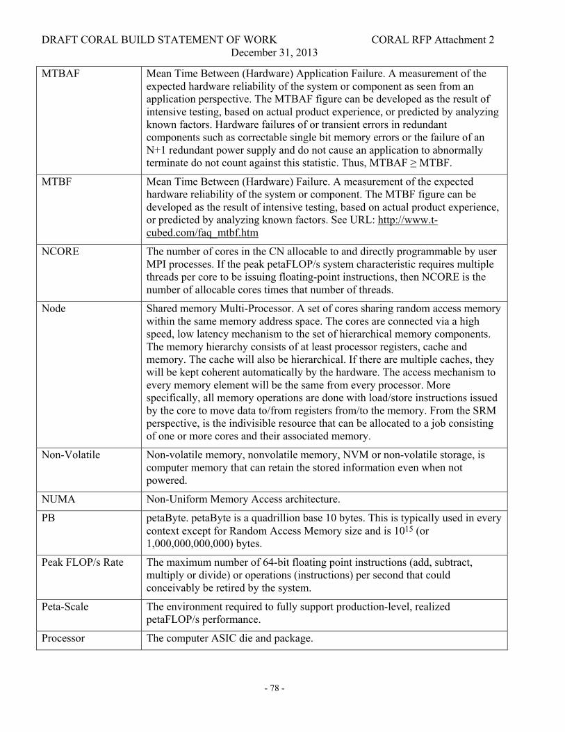
DRAFT CORAL BUILD STATEMENT OF WORK CORAL RFP Attachment 2 December 31, 2013
- 78 -
MTBAF Mean Time Between (Hardware) Application Failure. A measurement of the expected hardware reliability of the system or component as seen from an application perspective. The MTBAF figure can be developed as the result of intensive testing, based on actual product experience, or predicted by analyzing known factors. Hardware failures of or transient errors in redundant components such as correctable single bit memory errors or the failure of an N+1 redundant power supply and do not cause an application to abnormally terminate do not count against this statistic. Thus, MTBAF ≥ MTBF.
MTBF Mean Time Between (Hardware) Failure. A measurement of the expected hardware reliability of the system or component. The MTBF figure can be developed as the result of intensive testing, based on actual product experience, or predicted by analyzing known factors. See URL: http://www.t-cubed.com/faq_mtbf.htm
NCORE The number of cores in the CN allocable to and directly programmable by user MPI processes. If the peak petaFLOP/s system characteristic requires multiple threads per core to be issuing floating-point instructions, then NCORE is the number of allocable cores times that number of threads.
Node Shared memory Multi-Processor. A set of cores sharing random access memory within the same memory address space. The cores are connected via a high speed, low latency mechanism to the set of hierarchical memory components. The memory hierarchy consists of at least processor registers, cache and memory. The cache will also be hierarchical. If there are multiple caches, they will be kept coherent automatically by the hardware. The access mechanism to every memory element will be the same from every processor. More specifically, all memory operations are done with load/store instructions issued by the core to move data to/from registers from/to the memory. From the SRM perspective, is the indivisible resource that can be allocated to a job consisting of one or more cores and their associated memory.
Non-Volatile Non-volatile memory, nonvolatile memory, NVM or non-volatile storage, is computer memory that can retain the stored information even when not powered.
NUMA Non-Uniform Memory Access architecture.
PB petaByte. petaByte is a quadrillion base 10 bytes. This is typically used in every context except for Random Access Memory size and is 1015 (or 1,000,000,000,000) bytes.
Peak FLOP/s Rate The maximum number of 64-bit floating point instructions (add, subtract, multiply or divide) or operations (instructions) per second that could conceivably be retired by the system.
Peta-Scale The environment required to fully support production-level, realized petaFLOP/s performance.
Processor The computer ASIC die and package.

DRAFT CORAL BUILD STATEMENT OF WORK CORAL RFP Attachment 2 December 31, 2013
- 79 -
Scalable A system attribute that increases in performance or size as some function of the peak rating of the system.
SECDED Single Error Correction Double Error Detection. Storage and data transfer protection mechanism that can detect parity errors (single bit errors) and detect storage or data transfer errors with multiple bits in them.
SIMD Single Instruction, Multiple Data (SIMD) instructions are processor instructions that operate on more than one set of input 64b or 32b floating-point values and produce more than one 64b or 32b floating-point value. Fused Multiply-Add (FMA) instructions are not SIMD. Examples of this are x86-64 SSE2 and Power VMX instructions.
Thread Hardware threads are typically exposed to through the operating system as independently schedulable sequences of instructions. A hardware thread executes a software thread within a Linux (or other) OS process.
TB TeraByte. TeraByte is a trillion base 10 bytes. This is typically used in every context except for Random Access Memory size and is 1012 (or 1,000,000,000,000) bytes.
TLB Translation Look-aside Buffer (TLB) is a set of content addressable hardware registers on the processor that allows fast translation of virtual memory addresses into real memory addresses for virtual addresses that have an active TLB entry.
TFLOP/s teraFLOP/s. Trillion (1012 = 1,000,000,000,000) 64-bit floating point operations per second.
UMA Uniform Memory Access architecture. The distance in core clocks between core registers and every element of node memory is the same. That is, load/store operations that are serviced by the node memory have the same latency to/from every core, no matter where the target physical location is in the node memory assuming no contention.
15.2 Software
32b executable Executable binaries (user applications) with 32b (4B) virtual memory addressing.
64b executable Executable binaries (user applications) with 64b (8B) virtual memory addressing.
API Application Programming Interface: Syntax and semantics for invoking services from within an executing application.
Baseline Languages The Baseline Languages are Fortran08, C, C++ and Python.

DRAFT CORAL BUILD STATEMENT OF WORK CORAL RFP Attachment 2 December 31, 2013
- 80 -
BIOS Basic Input-Output System (BIOS) is low level (typically assembly language) code usually held in flash memory on the node that tests and functions the hardware upon power-up or reset or reboot and loads the operating system.
BOS Base Operating System (BOS). Linux (LSB 3.1) compliant Operating System run on the ION and FEN.
CDTI The hierarchal Code Development Tools Infrastructure (CDTI) components are distributed throughout the CORAL system. Individual code development tool “front-end” components that interact with the user execute on the FEN (although the display may be remoted via an X-Window). Code development tool communications mechanisms interface the tool “front-ends” running on the FEN with the user application running on the CN through a single level fan-out hierarchy running on the ION.
Current standard Term applied when an API is not “frozen” on a particular version of a standard, but will be upgraded automatically by Offeror as new specifications are released
Fully supported
A software product-quality implementation, documented and maintained by the HPC machine supplier or an affiliated software supplier.
Job An allocation of resources to a user for a specified period of time. The user should be given control over which resources can be allocated to a job.
CNOS Light-Weight Kernel providing operating system functions to user applications running on CN.
OS Operating System
Published
(as applied to APIs):
Where an API is not required to be consistent across platforms, the capability lists it as “published,” referring to the fact that it will be documented and supported, although it will be Offeror- or even platform-specific.
RPCTI Remote process control code development tools interface that allows code development tools to interface from the FEN to the CNOS on the CN and operate on user processes and threads on the CN.
Single-point control
Refers to the ability to control or acquire information on all processes/PEs using a single command or operation.
Standard
(as applied to APIs)
Where an API is required to be consistent across platforms, the reference standard is named as part of the capability.
Task A process launched as a job step component, typically an MPI process.