Embed Size (px)
Citation preview

DRAFT BEST MANAGEMENT
WETLANDS PRACTICES
FOR AGRICULTURE JANUARY 22, 2016
MARCH 2, 2016
MARCH 14, 2016
JANUARY 31, 2018

1
TABLE OF CONTENTS
Chapter I – Introduction
Chapter II – Planning
Chapter III – Access
Access Road
Stream Crossing
Conservation Cover
Structure for Water Control
Chapter IV – Field Improvements
Bedding
Brush Management
Channel Bank Vegetation
Diversion
Surface Drainage-Field Ditch
Subsurface Drainage
Terrace
Land Smoothing
Obstruction Removal
Underground Outlet
Chapter V – Ponds Water Supply and Irrigation
Pond
Irrigation Storage Reservoir
Dike

2
Irrigation Water Conveyance
Spring Development
Water Well
Fencing
Pipeline
Chapter VI – Stabilization and Erosion Control
Filter Strip
Grade Stabilization Structure
Grass Waterway or Outlet
Level Spreader
Lined Waterway or Outlet
Sediment Basin
Riparian Forest Buffer
Stormwater Runoff Control
Chapter VII – Waste Management Systems
Nutrient Management
Agrichemical Handling Facility
Heavy Use Area Protection
Roof Runoff Management
Waste Storage Pond
Waste Storage Structure
Appendix - Definitions
3
CHAPTER I
Introduction
Agriculture is a cornerstone of New Hampshire’s scenic landscape and rich community heritage contributing significantly to the State’s economy. Farming in New Hampshire has significantly evolved as it adapts to increasing urbanization and globalization. Loss of farmland and the pressures of encroaching development and increased regulation present challenges to farm businesses. At the same time, this proximity of rising populations and affluence creates demand for fresh, locally produced farm products and services, and raises awareness of the values of the region’s rich agricultural traditions. (The New Hampshire Farm Viability Task Force Report).
Agricultural lands can play a significant part in the abundance and the quality of New
Hampshire’s lakes, streams and wetlands. The term “water quality” is more than water clarity.
Water quality encompasses the chemical, physical, and biological properties of water in lakes,
streams and wetlands.
Maintenance or improvement of existing crop or pasture land for continued agricultural use
which impacts wetlands are under the NH Wetlands Bureau jurisdiction. Utilizing the Best
Management Wetland Practices (BMWP) for minimizing impacts in agricultural operations
under Board permit process can ensure that minimum environmental impact will occur to
wetlands.
This publication is primarily a reference and a planning tool to assist agricultural producers to
become better informed about best management practices for reducing soil erosion and
sedimentation from agricultural operations that affect wetlands. When using this publication, it
is important to remember that for every situation encountered, there may be more than one
correct method to prevent or minimize erosion and sedimentation.
What This Handbook Is
This handbook describes Best Management Practices, or BMPs, for protecting water quality and
wetlands associated with farming operations. A Best Management Practice is a method or
practice which, when installed or used, is consistent with efficient, practical, technically and
environmentally sound animal or crop production practices. BMPs are those practices best
suited to preventing, reducing, or correcting agriculture-related problems. (NPS report, October
1991). The BMPs include a wide range of recommended techniques that if used in combination
with professional judgement, will provide protection for our wetland resources. This handbook
is for farmers, agricultural professionals and others involved in agricultural land management.
This handbook will help you understand, identify, design, and implement water quality
protection measures while meeting other farm objectives.

4
This book will help you to:
Understand how BMPs work. It is more effective, cheaper, and easier to prevent
pollution than to fix problems after they occur. When you understand the principles
behind BMP techniques, you will be able to anticipate and prevent problems before
they end up costing you time and money.
Decide which BMPs to use. Farming activities are quite diverse, as are the site conditions
upon which farming are practiced
Apply BMP principles, allowing you to use your own judgment along with this handbook
to select the most appropriate and effective BMPs for a particular site.
What This Handbook Is Not
BMPs may not be the same as regulations. Best Management Practices are procedures that,
when used appropriately, will result in the greatest protection of the environment over the
course of the operation.
Regulations describe required minimally acceptable practices. BMPs are mandatory in some
situations; others may be voluntary, depending on the site. If the agricultural operation impacts
wetlands or surface waters (by traveling across them), BMPs are mandatory and a New
Hampshire Dept. Of Environmental Services (NH DES) wetland dredge and fill permit may be
required. In addition, many towns with local wetland regulations, designated prime wetlands,
and wetland setbacks may require local permitting if work is done in those areas.
This handbook focuses on water quality and wetland BMPs. There are BMPs that protect
wildlife habitat, soil integrity and productivity, aesthetics, and other aspects of the agricultural
operation. Although these values are important, they are not the primary focus of this manual.
How to Use This Handbook
The BMP manual is most effective when used as a resource for planning an agricultural land
management system. It provides information about why water quality is important and how to
protect it. In addition, the BMP manual provides tips and techniques that assist land managers
with low-cost and effective methods for protecting water quality while constructing roads,
stream and wetland crossings, maintaining ponds and drainage improvements. If you are new
to BMPs, it is best to read the publication all the way through to get a sense of the content,
layout, glossary and other resources available.
The intent is to develop a conservation system comprised of one to several BMPs that address a
particular management concern while minimizing or eliminating impacts to wetlands. The
chapters cover planning; access; field improvements; ponds, water supply and irrigation;
stabilization and erosion control; and waste management systems. The Appendix contains a
detailed set of standards and specifications for each BMP that are referred to in the chapters
5
1. How Agriculture Affects Water Quality
Agricultural land management can directly impact water quality by affecting sediment,
nutrients (phosphorus and nitrogen), bacteria and pesticides. Additionally, biotic impairments
exist that may be attributed to any combination of these those mentioned above. Conventional
pollutants, habitat loss, modified hydrology and/or any other factors may prevent
establishment of plants and animals expected to be found in a particular water body.
Increased organic and inorganic nutrients.
Applying nutrients in excess of a crop’s requirements can result in the excess reaching
surface or ground water through erosion or leaching.
Excess pesticides.
Pesticides applied contrary to labelled instructions for use may reach surface or ground
water.
Reduce the soil’s infiltration capacity.
This can occur any time the soil and/or surface is disturbed, removed, compacted, or
otherwise damaged.
Increase potential soil erosion.
The opportunity for soil to be carried away by runoff increases greatly when soil is exposed
or fill is used.
Divert water flows.
Roads and tillage patterns can block or intercept water moving over or through the soil. The
more water that accumulates, the greater the chance that it will form a channel and start
eroding soil.
Concentrate water flows.
Roads, waterways, diversions, terraces, and their associated drainage structures can collect
and funnel runoff, creating rills or gullies. In these situations, water erodes and transports
exposed soil in its path.
Diminish the benefits of vegetation next to waterbodies.
Removing buffers and tilling to the edge of water courses may reduce filtering and uptake
of pollutants in runoff, shade on the water’s surface, reduce the amount of natural woody
debris, or eliminate leaf litter that is an important food source for aquatic life. In addition,
the more open agricultural land in a watershed can increase the amount of water moving
through the soil into streams, and in some instances, increase flooding.

6
2. How BMPs Protect Water Quality
Control Water Flow
Plan how water moves within and around the harvest area and decide how water flow will be controlled.
Concentrated flows of water on roads, skid trails, landings, and in drainage systems develop more force and a greater ability to erode soil and carry sediment.
Control small volumes of water before they converge and accumulate into concentrated flows.
Slow down runoff and spread it out. Many BMPs work by directing small amounts of water into areas of undisturbed forest floor where it can be absorbed.
Minimize and stabilize exposed soil
Limit soil disturbance and stabilize areas where mineral soil is exposed. These practices are most critical in and around riparian management zones —forest areas bordering water bodies.
Protect exposed soil, which can erode very rapidly. Most of the sediment that ends up in streams near managed forests comes from exposed soil on roads, landings, and skid trails.
Know where the riparian management zones are and how to protect their capacity to absorb and filter runoff
Stabilize areas of exposed soil, within riparian management zones and in other locations where runoff has the potential to reach water body or wetland.

7
Using BMPs during or immediately after the harvest prevents exposed soil or fill from eroding.
Protect the integrity of water bodies
Protect stream channels and banks. Blocking or altering streams (with slash, for instance) may keep fish from swimming past the blockage. Damaged stream banks erode quickly causing sedimentation and siltation. By protecting the physical integrity of streams, BMPs prevent fish passage issues.
Leave enough shoreland vegetation to maintain water quality. BMPs maintain the benefits that nearby trees and plants provide water bodies. Stream side vegetation shades the water, minimizing temperature changes. Live roots stabilize the banks and maintain the soil’s physical and chemical properties. Trees, along the banks, drop leaf litter and woody debris that supply nutrients and provide some habitat for plants and animals in the stream. Shoreland vegetation plays and important role in maintaining water quality.
Handle nutrients and pesticides safely
3. New Hampshire’s Water Resources
New Hampshire has hundreds of lakes and ponds, large areas of forested and non-forested
wetland, and thousands of miles of streams and rivers. All these forest waterbodies, and the
areas that drain to them, are connected by moving water. This BMP handbook is designed to
help protect them.
WATERSHED
A watershed is all the land and waterbodies from which water drains to a given point. You can
define a watershed for an entire lake, for a stream at a crossing site, or for a river where it
reaches the ocean. Watersheds range in size from just a few acres (for a small stream), to
thousands of acres (for a large river). All land is part of some watershed.
It is crucial to understand where water is coming from and draining to in the watershed where there is farming. The amount of open agricultural land at higher elevations can affect the amount and timing of runoff at lower elevations within the same watershed. When you know
where, when, and how much water flows in the agricultural area, you will be able to determine the best locations for roads, the size of constructed swales and the size of any crossing and therefore what types of BMPs you will need to control water movement.
8
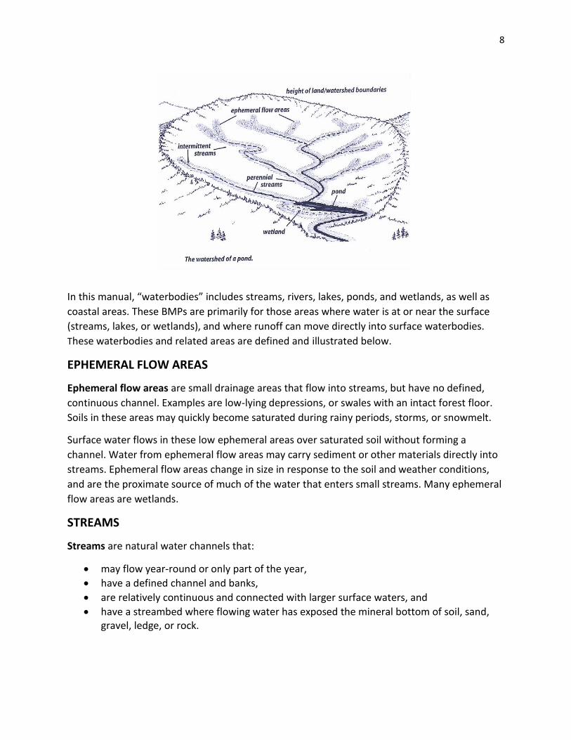
In this manual, “waterbodies” includes streams, rivers, lakes, ponds, and wetlands, as well as
coastal areas. These BMPs are primarily for those areas where water is at or near the surface
(streams, lakes, or wetlands), and where runoff can move directly into surface waterbodies.
These waterbodies and related areas are defined and illustrated below.
EPHEMERAL FLOW AREAS
Ephemeral flow areas are small drainage areas that flow into streams, but have no defined,
continuous channel. Examples are low-lying depressions, or swales with an intact forest floor.
Soils in these areas may quickly become saturated during rainy periods, storms, or snowmelt.
Surface water flows in these low ephemeral areas over saturated soil without forming a
channel. Water from ephemeral flow areas may carry sediment or other materials directly into
streams. Ephemeral flow areas change in size in response to the soil and weather conditions,
and are the proximate source of much of the water that enters small streams. Many ephemeral
flow areas are wetlands.
STREAMS
Streams are natural water channels that:
may flow year-round or only part of the year,
have a defined channel and banks,
are relatively continuous and connected with larger surface waters, and
have a streambed where flowing water has exposed the mineral bottom of soil, sand, gravel, ledge, or rock.

9
Forest streams in New Hampshire vary widely in how much water they carry, how steep they
are, the shape of the streambed or channel, how much area they drain, and when they flow.
Perennial streams
generally flow year-round
range from small brooks to large rivers
Intermittent streams
flow only a few months of the year, or during wet seasons.
The normal high water mark is the place on the stream bank where the highest water levels
typically occur, often during spring runoff. You can identify it from features like undercutting of
the bank; a change in the type of vegetation; exposed roots that do not penetrate beyond a
certain level; root scars; and water stains on rocks, stems, roots, or other vegetation.
WETLANDS
Wetlands are areas where soils are saturated or flooded at least part of the year, and where
water-loving plants are often found. Wetland soils usually have developed special
characteristics which reflect that water is at or near the surface sometime of the year.
Wet meadows are herb-dominated wetlands typically with non-woody vegetation less than 3
feet in height, saturated for long periods during the growing season, but seldom flooded. Wet
meadows develop on predominantly poorly drained soils (NH DES Env-Wt 101). Wet meadows
are typically managed areas that would otherwise revert to forested wetlands. Most wetland
impacts covered by a NH DES Minimum Impact Agricultural permit are limited to wet meadows
Forested wetlands are dominated (or potentially dominated) by trees taller than 20 feet.
Forested wetlands vary widely in their characteristics, often have relatively little water directly
at the surface, and have indistinct borders. They may require considerable expertise to identify.
Forested wetlands are often managed for timber, with roads and trails crossing them, and they
may be considered for expanding the agricultural land base for farms. It is critical that they be
evaluated by a professional soil or wetland scientist before being cleared for agriculture. The
Minimum Impact Agricultural permit cannot be used for impacts to forested wetlands.
Bogs (non-forested or open wetlands) are not dominated by trees, though they may have
some scattered trees, mostly less than 20 feet tall. They have water at or near the surface at
least part of the year, and may have a more or less distinct border defined by the surrounding
forest. The high water and organic content of wetland soils make them considerably weaker
than upland soils and difficult to work in. The NH DES Minimum Impact Agricultural permit
cannot be used to affect a bog.

10
Vernal pools are a type of wetland, typically forested, which provide specialized habitat for
amphibians and reptiles and deserve special attention. They are small, seasonal wetlands that
lack and inlet and outlet and lack fish populations. During the dry seasons they may only be
recognizable as an isolated depression in the forest floor. A wide variety of other wildlife
species also use vernal pool habitats, including several threatened and endangered species.
Separate guidelines for identifying vernal pool habitat are available from the NH Fish & Game
Department, Non-game and Endangered Species Program. Further information regarding
recommended practices for timber harvesting near vernal pools can be found in section 7.3 of
Good Forestry in the Granite State: Recommended Voluntary Forest Management Practices for
New Hampshire, 2010.
Wetlands Characteristics:
Hydrology, or the presence of water in or above the soil;
Signs of wetland hydrology include:
During most years, the area has ponding, flooding, or a water table within 12” of the soil surface for 14 or more consecutive days during the growing season (bud burst to leaf fall);
Water stained (dark) or silt covered leaves;
Lines of organic debris such as leaf litter on tree and shrub stems above soil surface;
Water or silt stained plant stems;
Swollen bases of tree trunks (an adaptation to wet soils);
Exposed plant roots (an adaptation to wet soils).
Soils, which show observable features when saturated or flooded for long periods of time;
Signs in the soil include:
Sphagnum moss on the surface;
A thick upper layer of peaty to mucky organic matter;
Soils mostly neutral grey in color directly beneath the dark topsoil or grey soils with rust colored (orange-brown and yellow-brown) splotches within 12" of the surface.
Vegetation, which is usually composed of a dominance of species suited to hydric (largely
anaerobic) soil conditions. In an agricultural setting the mix and density of plants may be altered
through management so observing similar adjoining sites may be necessary.
Signs in the composition of plant species include:
More than half the plant species are those that grow most often in wetland soils. Plant species have been classified by the US Fish & Wildlife Service based on how frequently they occur in wetlands. The species are grouped into five categories, listed here from most to least wetland adapted:

11
Obligate Wetland Species
Species occur more than 99% of the time in wetlands.
Facultative Wetland Species
Species occur between 67-99% of the time in wetlands.
Facultative Species
Species occur equally in uplands and wetlands.
Facultative Upland Species
Species occur between 1-33% of the time in wetlands.
Obligate Upland Species
Species occur less than 99% of the time in wetlands.
4. What is Section 404 of the Clean Water Act? Section 404 of the Clean Water Act defines wetlands as"...those areas that are inundated or saturated by surface water or groundwater at a frequency and duration sufficient to support, and under normal circumstances do support, a prevalence of vegetation typically adapted for life in saturated soil conditions.". Section 404 of the Clean Water Act lists specific agricultural and silvicultural activities which are exempt from regulation, even though these activities occur on "jurisdictional wetlands." The regulatory agency which administers Section 404 of the Clean Water Act is the USACOE in consultation with the U.S. Environmental Protection Agency, the U.S. Department of Interior Fish and Wildlife Service, the National Marine Fishery Service and the U.S.D.A. Natural Resources Conservation Service (NRCS). The NRCS can provide information on federal wetlands criteria, wetland determinations on agricultural lands, information on wetland soil characteristics, and interpretations and information on federal rules and regulations concerning administration of its programs. 5. What Farming and Forestry Activities are Exempt from Section 404 of the Clean Water
Act?
There are basically two main provisions under Section 404 that must be satisfied for a farming activity to be exempt. Under Section 404(f)(1), a discharge is exempt only if it is associated with certain ongoing farming, silviculture, and ranching activities. Under Section 404(f)(2), known as the "recapture provision," the discharge continues to be exempt only if the activity does not bring an area of waters into a new use and impair the flow and circulation of the waters or reduce their reach. Exempt activities are: established (i.e., ongoing), normal farming activities such as: plowing, seeding, cultivating, harvesting and minor drainage for the production of food

12
or fiber, maintenance (but NOT construction) of drainage ditches (the term "maintenance" includes removal of accumulated silt and debris, but does not include widening, deepening, realigning or extending the length of existing drainage ditches), construction and maintenance of irrigation ditches, construction and maintenance of farm or stock ponds (to provide water for livestock or irrigation as long as the size and location of the pond are proportionate to the quantity of water needed to support the principal farming operation) construction and maintenance of farm and forest roads, in accordance with BMPs. The list above is only a summary. The full text of the federal law can be found in Section 404 of the Clean Water Act. Many clarifications and examples are found in the USACOE implementing regulations and interagency memoranda. (For further details the following Internet address can be accessed: http://www.usace.army.mil/net/functions/cw/cecwo/reg with 404f.htm, sec404.htm, 33cfr323.htm#323.4, and cwaag.htm). To be exempt under Section 404 of the Clean Water Act, the farming or silvicultural activity must be part of an ongoing farming or silvicultural operation and cannot be associated with converting a wetland to agricultural or silvicultural production, or converting an existing agricultural or silvicultural wetland into non-wetland area. Wetlands which were hydrologically altered and converted to produce an agricultural commodity (meaning an annually tilled crop) prior to December 23, 1985, and which were or are used for commodity crop production and remain in agricultural use, are identified as "prior converted croplands" when designated by NRCS. Such wetlands are not under the jurisdiction of Section 404 unless the activities that resulted in the conversion involved the unauthorized discharge of dredged or fill material into wetlands or other waters. Agricultural wetlands which have not been used, managed or maintained for cropping purposes in the last five years are considered abandoned and generally are subject to regulation under Section 404. Areas that are inundated for longer than 14 days during the growing season are not prior converted but "farmed wetlands" and remain under Section 404 jurisdiction.
It is important to note that some activities exempted under federal regulation, such as
construction of farm ponds or farm roads, may not be exempt under state and local
regulations. For exempted activities under state regulations see NH DES wetland rules Section
Env-Wt 303.05.
13
CHAPTER II
Planning
Farm management activities should follow a well-thought-out plan that protects soil and water
resources. Landowners considering improving or maintaining, access, filling, improving or
developing water sources, or improving drainage to fields should consult their county
conservation district, their local NRCS office or county extension professional for assistance and
an on-the-ground evaluation.
A variety of tools can help in evaluating the property and developing a plan for land
management activities. These tools include aerial photography, soil surveys, soil survey maps,
topographic maps, and property survey maps or tax maps.
Walk the property to identify areas of special concern such as streams, ponds, wetlands and
nesting sites. Consider strategies to avoid sensitive areas and/or minimize the foot print of the
proposed work. Establish objectives and priorities for the management activities.
Planning not only means identifying the management activities but also the timing of carrying
out the activity. Timing is one of the most effective Best Management Practices. Operating
when the ground is dry, frozen, snow covered, or when the water levels are low, is an excellent
way to reduce or eliminate erosion and sedimentation.
Plan to take additional precautions or even to suspend the management activity until
conditions permit.
Steps
Once the site evaluation has been completed, follows these recommendations to plan
management activities:
Make a tentative list of site specific BMPs needed to protect water quality for proposed
management activities in or adjacent to wetlands.
Review the farm conservation plan and landowner objectives for the site.
Identify on a map (topographic, aerial photo or county soil map) the following:
o Property and field boundaries
o Public roadways
o Problem areas, wet and unstable soils, eroding slopes and or gullies, soils
and limitations, stormwater runoff locations
o Existing and planned farmstead and access road system
o Areas to avoid (streams, wetlands, water bodies, steep slopes (>30%),
unstable soils and flood plains)
o Farmstead equipment maintenance, manure storage, pesticide and
fueling areas

14
o Existing and potential stream crossing locations, include estimates of
drainage areas and landuse
o Existing and potential riparian buffers, natural and manmade
o Other sensitive areas such as habitat areas of endangered or threatened
species, known nesting sites, etc.
Mark roads, stream crossings, wetland crossings and specific devises to be used. Take
advantage of natural features that will make construction easier and drainage most
effective.
Consider weather and ground conditions when scheduling earth moving activities.
o Avoid wet seasons and plan water crossings (installation or bridges and
culverts) for summer months when water is low.
o On wet sites and when working in or adjacent to wetlands, time
operations to coincide with frozen ground.
CHAPTER III
ACCESS
Intent
The intent when using these practices is to
avoid wetlands if possible and if not to
minimize impacts to the wetlands by
protecting characteristics, functions and
values. Typically, the wetlands affected by
these practices are classified as Wet
Meadow, and occur in an agricultural field
and have hydric soils that are defined as
soils that, in an undrained condition, are
saturated, flooded, or ponded long enough
during a growing season to develop an
anaerobic condition that supports the
growth and regeneration of hydrophytic
vegetation. Additional jurisdictional
wetland areas may include forested
wetlands, intermittent stream, farm ponds
or other areas that support and are
necessary to an existing agricultural
operation. The access would have to meet
qualifying criteria that is set in rules and
defined as Minimum..
ACCESS ROAD
Definition
A travel way for equipment and vehicles
constructed as part of a conservation
system.
Purpose
To provide for an efficient transportation
system for removing agricultural products
while also protecting agricultural land and
water quality, for agricultural access, or
other needed agricultural management
activities.
1
Conditions Where Practice Applies
Where area and volume to be harvested
makes it necessary and economically
feasible to install such a road system.
Guidelines
• A well thought out efficient
transportation system will minimize the
area disturbed and vulnerable to
erosion.
• Keep the length of the truck road to a
minimum. Have gravel or wood chips for
about 200 feet prior to entering on a
public highway to reduce the amount of
mud on the highway.
• Road grades should be kept to 10% or
less. Steeper grades are permissible for
short distances. Long level sections are
difficult to drain properly. Grades
between 3% and 5% are desirable.
• Place roads on high ground with gentle
grades. Avoid sharp curves. Fifty foot
minimum radius for large trucks.
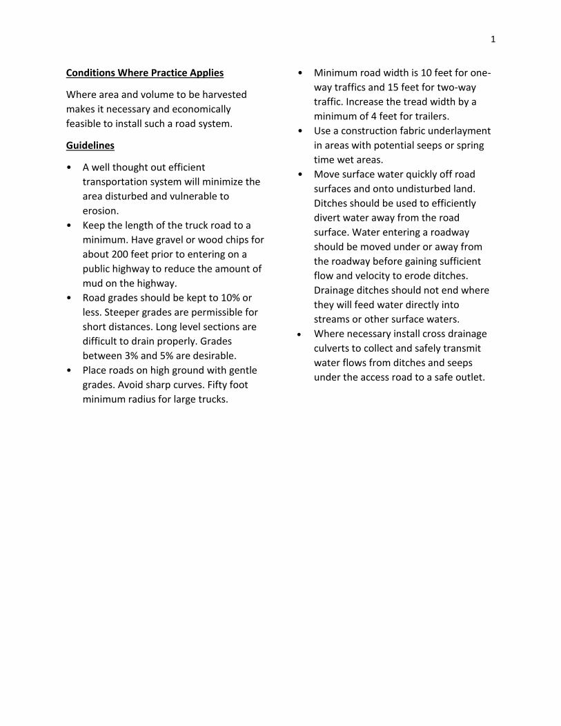
• Minimum road width is 10 feet for one-
way traffics and 15 feet for two-way
traffic. Increase the tread width by a
minimum of 4 feet for trailers.
• Use a construction fabric underlayment
in areas with potential seeps or spring
time wet areas.
• Move surface water quickly off road
surfaces and onto undisturbed land.
Ditches should be used to efficiently
divert water away from the road
surface. Water entering a roadway
should be moved under or away from
the roadway before gaining sufficient
flow and velocity to erode ditches.
Drainage ditches should not end where
they will feed water directly into
streams or other surface waters.
Where necessary install cross drainage
culverts to collect and safely transmit
water flows from ditches and seeps
under the access road to a safe outlet.
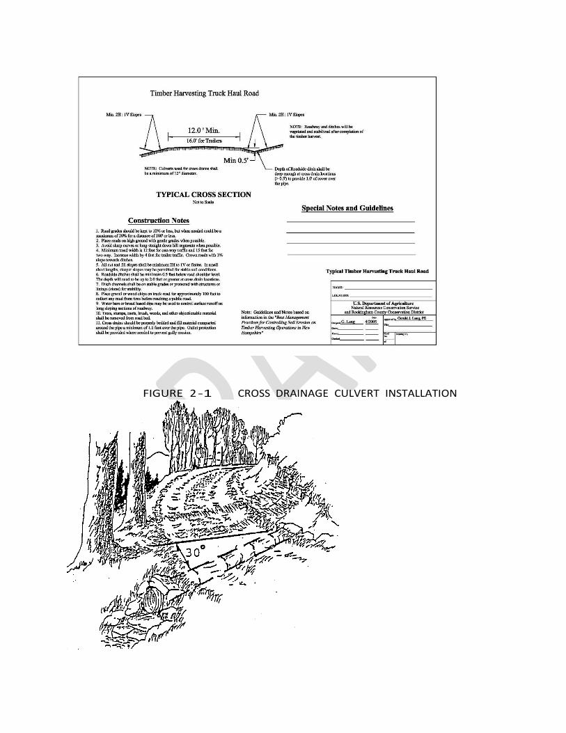
FIGURE 2 -1 CROSS DRAINAGE CULVERT INSTALLATION
1
Source: Best Management Practices for Erosion Control
If streams must be crossed, do so by the
most direct route and preferably at right
angles to the stream. A bridge, culvert,
or ford of acceptable design may be
required.
Road grades approaching stream
crossings shall be broken and surface
water dispersed before it reaches the
watercourse.
Restrict vehicle traffic on soft roads
during the wet season of the year.
Restrict vehicle traffic during heavy
rains.
Check with the State of New Hampshire
Department of Transportation or the
local town officials to determine if a
driveway permit is required.
Vegetated exposed areas of soil that are
subject to erosion.
Restrict access where necessary to
protect road. Install gate or other
barrier to exclude traffic.
Annual and after significant rain fall
events inspect the road surface and
drainage structure and repair and/or
clean out as necessary.
STREAM CROSSING
Definition
A stabilized area or structure constructed
across a stream to provide a travel way for
people, livestock, equipment, or vehicles.
Purpose
Provide access to another land unit
Improve water quality by reducing
sediment, nutrient, organic, and
inorganic loading of the stream
Reduce streambank and streambed
erosion
. .

1
Conditions Where Practice Applies
This practice applies to all land uses where
an intermittent or perennial watercourse
exists and a ford, bridge, or culvert type
crossing is needed.
Criteria
Apply this standard in accordance with all
local, State, Tribal, and Federal regulations,
including flood plain regulations and
flowage easements.
Identify significant cultural resources or
threatened or endangered species that
could be affected by the implementation of
the practice.
Location. Locate stream crossings in areas
where the streambed is stable or where it
can be stabilized (see NRCS Conservation
Practice Standard, Channel Bed
Stabilization, Code 584). Do not place
crossings where channel grade or alignment
changes abruptly, excessive seepage or
instability is evident, overfalls exist
(evidence of incision and bed instability),
where large tributaries enter the stream, or
within 300 feet of known spawning areas of
listed species. Avoid wetland areas.
Discourage livestock loafing in the stream
by locating crossings, where possible, out of
shady riparian areas or by including gates in
the design.
Install stream crossings perpendicular to
the direction of stream flow where possible.
Fully consider the natural lateral migration
pattern of the stream in the design. Avoid
skews on all but the smallest streams.
Access Roads. Where the stream crossing is
installed as part of a roadway, size the
crossing according to NRCS Conservation
Practice Standard, Access Road.
Width. Provide an adequate travel-way
width for the intended use. Make
“livestock- only” crossings no less than 6
feet wide and no more than 30 feet wide, as
measured from the upstream end to the
downstream end of the stream crossing,
not including the side slopes.
Side Slopes. Make all side slope cuts and
fills stable for the channel materials
involved. Make the side slopes of cuts or
fills in soil materials no steeper than 2
horizontal to 1 vertical (2:1). Make rock cuts
or fills no steeper than 1.5 horizontal to 1
vertical (1.5:1).
Stream Approaches. Blend approaches to
the stream crossing with existing site
conditions, where possible. Use streambank
soil bioengineering practices as appropriate
and feasible. Make the approaches stable,
with gradual ascent and descent grades
which are not steeper than 4 horizontal to 1
vertical (4:1), and of suitable material to
withstand repeated and long term use.
Make the minimum width of the
approaches equal to the width of the
crossing surface. Divert surface runoff
around the approaches to prevent erosion.
Direct roadside ditches into a diversion or
away from the crossing surface. Configure
the crossing approaches (gradient and
curves) to properly accommodate the
length and turning radii of vehicles using
the crossing.
Rock. All rock must be able to withstand
exposure to air, water, freezing, and
thawing. Use rock of sufficient size and
density to resist mobilization by design
2
flood flows. Use appropriate rock sizes to
accommodate the intended traffic without
damage to the livestock, people, or vehicles
using the crossing.
Fencing. Exclude livestock access to the
crossing through the use of fence and gates,
as needed. Install cross-stream fencing at
fords, with breakaway wire, swinging
floodgates, hanging electrified chain, or
other devices to allow the passage of
floodwater and large woody material during
high flows. Design and construct all fencing
in accordance with NRCS Conservation
Practice Standard, Fence, Code 382.
Vegetation. Plant all areas to be vegetated
as soon as practical after construction. If
completion does not coincide with
appropriate planting dates for permanent
cover, use a cover of temporary vegetation
to protect the site until permanent cover
can be established. Native or functioning-
as-native plant species are preferred. Use
NRCS Conservation Practice Standard,
Critical Area Planting, Code 342, where
vegetation is unlikely to become
established by natural regeneration, or
where acceleration of the recovery of
vegetation is desired. In areas where the
vegetation may not survive, use NRCS
Conservation Practice Standard, Heavy Use
Area Protection, Code 561.
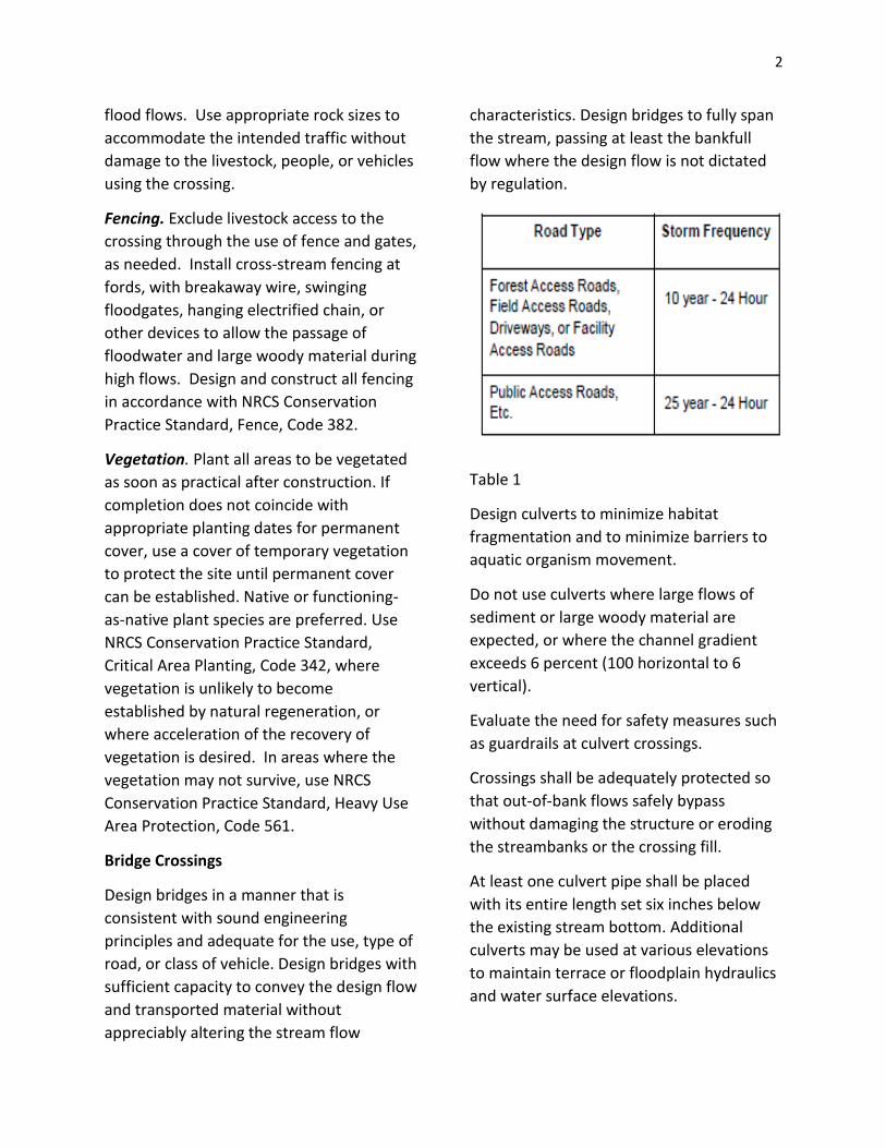
Bridge Crossings
Design bridges in a manner that is
consistent with sound engineering
principles and adequate for the use, type of
road, or class of vehicle. Design bridges with
sufficient capacity to convey the design flow
and transported material without
appreciably altering the stream flow
characteristics. Design bridges to fully span
the stream, passing at least the bankfull
flow where the design flow is not dictated
by regulation.
Table 1
Design culverts to minimize habitat
fragmentation and to minimize barriers to
aquatic organism movement.
Do not use culverts where large flows of
sediment or large woody material are
expected, or where the channel gradient
exceeds 6 percent (100 horizontal to 6
vertical).
Evaluate the need for safety measures such
as guardrails at culvert crossings.
Crossings shall be adequately protected so
that out-of-bank flows safely bypass
without damaging the structure or eroding
the streambanks or the crossing fill.
At least one culvert pipe shall be placed
with its entire length set six inches below
the existing stream bottom. Additional
culverts may be used at various elevations
to maintain terrace or floodplain hydraulics
and water surface elevations.

3
Make the barrel length of the culvert
adequate to extend the full width of the
crossing, including side slopes, and inlet or
outlet extensions. Unless an approved
headwall design is used, stable side slopes
shall have a minimum combined horizontal
protection length equal to 5 feet for every
one foot of vertical embankment, except
that neither upstream nor downstream
bank will be steeper than 2H:1V. Culvert
sections shall be joined by water-tight
couplers.
Acceptable culvert materials include
concrete, corrugated metal, corrugated
plastic, new or used high quality steel, and
any other materials that meet the
requirements of NRCS Conservation
Practice Standard, Structure for Water
Control, Code 587.
Ford Crossings
The following criteria apply to all ford
crossings:
Make the cross-sectional area of the
crossing equal to or greater than the
natural channel cross-sectional area. Make
a portion of the crossing depressed at or
below the average stream bottom elevation
when needed to keep base flows or low
flows concentrated.
Match ford shape to the channel cross-
section to the extent possible.
Provide cutoff walls at the upstream and
downstream edges of ford-type stream
crossings when needed to protect against
undercutting.
Evaluate the need for water depth signage
at ford crossings.
To the extent possible, the top surface of
the ford crossing shall follow the contours
of the stream bottom but in no case shall
the top surface of the ford crossing be
higher than 0.5 foot above the original
stream bottom at the upstream edge of the
ford crossing.
Make the downstream edge of the ford
crossing with a low-flow hydraulic drop less
than 0.5 foot above the original stream
bottom.
Concrete Fords
Use concrete ford crossings only where the
foundation of the stream crossing is
determined to have adequate bearing
strength.
Use concrete with a minimum compressive
strength of 3,000 psi at 28 days, with a ratio
of water to cementitious materials of 0.50
or less. Use coarse aggregate of 0.75 to 1
inch nominal size. If designed for freezing
conditions, use concrete with 4 to 8 percent
air-entrainment.
Use a minimum thickness of 5 inches of
placed concrete. Pour the concrete slab on
a minimum 4-inch thick gravel base, unless
the foundation is otherwise acceptable.
Construct toe-walls at the upstream and
downstream ends of the crossing. Make the
toe-walls a minimum of 6 inches thick and
18 inches deep. Extend the toe-walls in the
stream approaches to the bankfull flow
elevation.
Precast concrete panels may be used in lieu
of cast-in-place concrete slabs. To the
extent possible, the panels shall follow the
contours of the stream bottom in order to

4
avoid potential problems with sediment
accumulation. Use concrete units that have
adequate reinforcement for transportation
and placement.
Dewatering of the site and toe-walls is
required during placement of the concrete
to maintain the proper water/cement ratio.
Flowing water will erode concrete that is
not sufficiently hardened. The stream must
be diverted or retained from flowing over
the concrete for at least 12 hours after
placement of the concrete. During
construction, aquatic species must be
removed from the construction area
according to State protocols.
Rock Fords and the Use of Geosynthetics
Coarse aggregate or crushed rock ford
crossings are often used in steep areas
subject to flash flooding and where normal
flow is shallow or intermittent. When the
site has a soft or unstable subgrade, use
geotextiles in the design of rock ford
crossings.
Dewater and excavate the bed of the
channel to the necessary depth and width
and cover with geotextile material. Install
the geotextile material on the excavated
surface of the ford and extend it across the
bottom of the stream and at least up to the
bankfull flow elevation.
Cover the geotextile material with at least 6
inches of crushed rock. Use minimum 6-inch
deep geocells, if geocells are used. Use
durable geosynthetic materials and install
them according to the manufacturer's
recommendations, including the use of
staples, clips, and anchor pins.
Design all rock ford stream crossings to
remain stable for the bankfull flow.
Compute channel velocities and choose
rock size using procedures in NEH630;
NEH654 TS14N; and EFH Chapter 16
(NEH650), Appendix 16A, or other
procedures approved by the State
Conservation Engineer.
Where rock is used for ford crossings for
livestock, use a hoof contact zone or
alternative surfacing method over the rock.
Considerations
Avoid or minimize the use of or number of
stream crossings, when possible, through
evaluation of alternative trail or travel-way
locations. Assess landuser operations to
consolidate and minimize the number of
crossings. Where feasible, use existing
roads.
Evaluate proposed crossing sites for
variations in stage and discharge, tidal
influence, hydraulics, fluvial geomorphic
impacts, sediment transport and flow
continuity, groundwater conditions, and
movement of woody and organic material.
Increase crossing width or span to
accommodate transport of large woody
material in the flow.
Design passage features to account for the
known range of variation.
For culvert crossings, consider incorporating
natural streambed substrates throughout
the culvert length for passage of aquatic
organisms (see Bunt and Abt, 2001, for
sampling procedures). Natural streambeds
provide passage and habitat benefits to
many life stage requirements for aquatic

5
organisms and may reduce maintenance
costs.
Consider all life stages of aquatic organisms
in the stream crossing design to
accommodate their passage, in accordance
with the species’ requirements. Design
criteria are available in NEH Part 654,
Technical Supplement 14N, Fish Passage
and Screening Design; U.S Forest Service
low-water design guidance (USFS, 2006);
and stream simulation guidance
(USFS,2008). Each State also has specific
design criteria for culverts and stream
crossings (e.g., MassDOT, 2010). See also
Harrelson, et al. 1994, for stream reference
site descriptions.
Where a stream crossing is installed to
remove an existing barrier to the passage of
aquatic organisms, consider using NRCS
Conservation Practice Standard, Aquatic
Organism Passage, Code 396.
Consider relevant aquatic organisms in the
design and location of crossings to improve
or provide passage for as many different
aquatic species and age classes as possible.
Consider the habitat requirements of other
aquatic or terrestrial species that may be
affected by construction of a stream
crossing. For example, a crossing may be
designed with features that also promote
safe crossing by terrestrial vertebrates.
Ford crossings have the least detrimental
impact on water quality when their use is
infrequent. Ford crossings are adapted for
crossing wide, shallow watercourses with
firm streambeds. If the stream crossing is to
be used frequently, or daily, as in a dairy
operation, a culvert crossing or curbed
bridge should be used, rather than a ford
crossing.
Locate stream crossings to avoid adverse
environmental impacts and consider the
following:
Effects on upstream and downstream
flow conditions that could result in
increases in erosion, deposition, or
flooding. Consider habitat upstream and
downstream of the crossing to avoid
fragmentation of aquatic and riparian
habitats.
Short-term and construction-related
effects on water quality.
Overall effect on erosion and
sedimentation that will be caused by
the installation of the crossing and any
necessary stream diversion.
Effects of large woody material on the
operation and overall design of the
crossing.
Consider adding a well-graded rock
riprap apron on the downstream edge
of concrete crossings to dissipate flow
energy.
Ford crossings should not be placed
immediately downstream from a pipe or
culvert because of potential damage
from localized high velocity flows.
Plans and Specifications
Prepare plans and specifications for stream
crossings in keeping with this standard. The
plans and specifications must clearly
describe the requirements for applying the
practice to achieve its intended purpose.
As a minimum, include the following in
plans and specifications:

6
Location of stream crossing.
Stream crossing width and length with
profile and typical cross sections.
Design grades or slopes of stream
approaches.
Design flow calculations.
Thickness, gradation, quantities, and
type of rock or stone.
Type, dimensions, and anchoring
requirements of geotextile.
Thickness, compressive strength,
reinforcement and other special
requirements for concrete, if used.
Vegetative requirements that include
seed and plant materials to be used,
establishment rates, and season of
planting.
Location, type, and extent of fencing
required.
Method of surface water diversion and
dewatering during construction.
Location of utilities and notification
requirements.
Operation and Maintenance
Develop an operation and maintenance
plan and implement it for the life of the
practice.
Include the following items in the operation
and maintenance plan, as a minimum:
Inspect the stream crossing,
appurtenances, and associated fence
after each major storm event and make
repairs if needed.
Remove any accumulation of organic
material, woody material, or excess
sediment.
Replace surfacing stone used for
livestock crossing as needed.
REFERENCES
AASHTO, 2010. American Association of State Highway and Transportation Officials Load and
Resistance Factor Design (LRFD) Bridge Design Specifications, Customary U.S. Units,
5th Edition, with 2010 edits; ISBN Number: 1- 56051-451-0
Bunte, Kristin; Abt, Steven R. 2001. Sampling surface and subsurface particle-size distributions
in wadable gravel-and cobble-bed streams for analyses in sediment transport, hydraulics, and
streambed monitoring. Gen.
Tech. Rep. RMRS-GTR-74. Fort Collins, CO:
U.S. Department of Agriculture, Forest Service, Rocky Mountain Research Station. 428 p.
(http://www.fs.fed.us/rm/pubs/rmrs_gtr74.html )
Harrelson, Cheryl C; Rawlins, C. L.; Potyondy, John P, 1994. Stream channel reference sites: an
illustrated guide to field technique. Gen.
Tech. Rep. RM-245. Fort Collins, CO: U.S. Department of Agriculture, Forest Service, Rocky
Mountain Forest and Range Experiment Station. 61 p.
1
(http://www.stream.fs.fed.us/publications/PDFs/RM245E.PDF)
MassDOT, 2010. Design of Bridges and Culverts for Wildlife Passage at Freshwater
Streams. Massachusetts Department of
Transportation, Highway Division. (http://www.mhd.state.ma.us/downloads/projD
ev/Design_Bridges_Culverts_Wildlife_Passage_122710.pdf )
CONSERVATION COVER
Definition
Establishing and maintaining permanent
vegetative cover to protect soil and water
resources.
Purposes
Reduce soil erosion and sedimentation.
Improve water quality.
Enhance or create wildlife habitat.
Conditions Where Practice Applies
This practice applies on land to be retired
from agricultural production requiring
permanent protective cover, and on other
lands needing permanent protective cover.
This practice does not apply to plantings for
forage production or to critical area
plantings.
Criteria
General Criteria Applicable to All Purposes
Species shall be adapted to soil, range site,
and climate conditions. The New Hampshire
USDA Plant Hardiness Zone Map can help
determine proper species.
Species planted shall be suitable for the
planned purpose and site conditions. Use of
invasive species shall be avoided.
Seeding rates and methods shall be
adequate to accomplish the planned
purpose.
Planting dates, planting methods and care
in handling and planting of the seed or
planting stock shall ensure that planted
materials have an acceptable rate of
survival.
Only viable, high quality and adapted seed
or planting stock shall be used.
Legume seed shall be inoculated with the
proper Rhizobia bacteria before planting.
Site preparation shall be sufficient for
establishment and growth of selected
species.
Timing and use of equipment shall be
appropriate for the site and soil conditions.
Vegetative manipulation will be
accomplished by mechanical, biological or
chemical methods, by prescribed burning,
or a combination of the four. If burning is
used alone or in combination with the other
methods, Prescribed Burning, practice code
338, must be included as a planned
practice.
All nutrients shall be applied following the
nutrient management requirements in the
Field Office Technical Guide (FOTG).

1
Additional Criteria for Enhancing Wildlife
Habitat
Planting/Establishment
Grasses, forbs, and legumes shall be
planted in mixes to encourage maximum
plant diversity.
Management/Maintenance
Methods used shall be designed to protect
the soil resource from erosion.
Maintenance practices and activities shall
not disturb cover during the reproductive
period for grassland wildlife species.
Maintenance measures must be adequate
to control noxious weeds and other invasive
species.
To benefit insect food sources for grassland
nesting birds, spraying or other control of
noxious weeds shall be done on a “spot”
basis to protect forbs and legumes that
benefit native pollinators and other wildlife.
Considerations
This practice may be used to promote the
conservation of wildlife species in general,
including threatened and endangered
species.
Where applicable this practice may be used
to conserve and stabilize archeological and
historic sites.
Consider rotating management and
maintenance activities (e.g. mow only one-
fourth or one-third of the area each year)
throughout the managed area to maximize
spatial and temporal diversity.
Where wildlife management is an objective,
the food and cover value of the planting can
be enhanced by using a habitat evaluation
procedure to aid in selecting plant species
and providing or managing for other habitat
requirements necessary to achieve the
objective.
Use native species when available. Consider
trying to re-establish the native plant
community for the site. If a native cover
(other than what was planted) establishes,
and this cover meets the intended purpose
and the landowner's objectives, the cover
should be considered adequate.
Plans and Specifications
Specifications for this practice shall be
prepared for each site. They shall include,
but are not limited to, recommended
species, seeding rates and dates,
establishment procedures, and other
management actions needed to insure an
adequate stand.
Specifications shall be recorded using
approved specifications sheets, job sheets,
narrative statements in the conservation
plan, or other acceptable documentation.
Operation and Maintenance
Maintenance practices and activities should
not disturb cover during the primary
nesting period for grassland species in each
state.
Exceptions should be considered for
periodic burning or mowing when necessary
to maintain the health of the plant
community. Mowing may be needed during
the establishment period to reduce
competition from annual weeds. Noxious
weeds will be controlled to prevent

2
proliferation and spreading to adjacent
fields.
Annual mowing of the conservation cover
stand for general weed control is not
recommended.
Any use of fertilizers, pesticides and other
chemicals shall not compromise the
intended purpose.
1

2

3
STRUCTURE FOR WATER CONTROL (Bridges and Culverts)
Definition
A structure in an access, irrigation,
drainage, or other water management
system that conveys water, controls the
direction or rate of flow, or maintains a
desired water surface elevation.
Purpose
Water control structures are installed to
control the stage, discharge, distribution,
delivery, or direction of flow of water in
open channels, or water use areas. They are
also used for water quality control such as
sediment reduction or temperature
regulation. These structures are also used
to protect fish and wildlife and other
natural resources.
Conditions Where Practice Applies
This practice applies wherever a permanent
structure is needed as an integral part of an
irrigation, drainage, or other water control
system to serve one or more of the
following functions.
To provide conveyance for water over,
under, or along a ditch, canal, road,
railroad, or other barrier. Typical
structures: bridges; culverts; flumes;
inverted siphons; drop structures; or
catch basins.
Conduct water from one elevation to a
lower elevation within, to, or from a
ditch, channel, or canal. Typical
structures: culverts; drops; chutes;
turnouts; surface water inlets; head
gates; pump boxes; or stilling basins.
To protect pipelines from the entry of
trash, debris, or weed seeds. Typical
structure: debris screens.
To control water table or removal of
surface or subsurface water from
adjoining land, to flood land for frost
protection or to manage water levels for
wildlife or recreational purposes .
Typical structures: water level control
structures; pipe drop inlets; or box
inlets.
To modify water flow to provide habitat
for fish, wildlife, and other aquatic
animals. Typical structures: deflectors,
chutes; cold water release; or structures
for pools and riffles.
Water level control. Typical structures:
structures for recreation or similar
purposes, box inlets; pipe drop inlets; or
drop structures.
To control direction of channel flow
resulting from tides and high-water or
backflow from flooding. Typical
structure: tide and drainage gates.
To control the elevation of water in
drainage or irrigation ditches Typical
structure: checks dams.
To control the division or measurement
of irrigation water. Typical structures:
division boxes or water measurement
devices.
Does not apply to structural components of
pipeline, subsurface drains, or grade-
stabilization structures.
Considerations
General. Other general recommendations
for individual component design can be

4
used from the USDA Natural Resources
Conservation Service Engineering Field
Handbook where appropriate.
Downstream water volumes or peak
discharge rates may be reduced from the
installation of a water control structure
depending on the size of the structure,
drainage area, or pool area above the
structure.
Structures installed in brooks and streams
may have a negative effect on the water
quality during the installation period.
However, any structure impounding water
will have a positive long term effect on
water quality due to reduced sediment
transport, but increased water
temperatures may occur.
Site. Investigation. Adequate investigation
shall be made to insure that sufficient land
of suitable quality is available for the
intended use.
The land will be adequate in quantity
and quality for the use intended.
The structure site is stable and, when
the planned work of improvement is
installed, will perform as intended.
An adequate water supply is available.
Design Criteria
Structures shall be designed on an
individual job basis, or applicable USDA
Natural Resources Conservation Service
standard drawings shall be adapted, to
meet site conditions and functional
requirements. They shall be part of an
approved and overall farm or system plan
for an agricultural waste, irrigation,
drainage, wildlife facility, channel
improvement, or other water management
system.
The design plan shall specify the location,
grades, dimensions, materials, and
hydraulic· and structural requirements for
the individual structure· Provisions must be
made for necessary maintenance. Care
must be used to insure that the area's visual
resources are not damaged. If watercourse
fisheries are important, special precautions
or design features may be needed to insure
continuation of fish migration.
If soil and climatic conditions permit, a
protective cover of vegetation shall be
established on all disturbed earth surfaces.
If soil or climatic conditions preclude the
use of vegetation and protection is needed,
non-vegetative means, such as mulches,
gravel, or riprap may be used. In some
places, temporary vegetation may be used
until permanent vegetation can be
established. The structure can be fenced, if
necessary, to protect the vegetation.
Seedbed preparation, weeding, fertilization,
and mulching shall comply with the
vegetative BMWPs.
Hydrology. Peak flow and volume
determination shall be by approved USDA
Natural Resources Conservation Service
methods. The design discharge of an
associated structure, the hazard class of
overall design, or the discharge from the 10
percent chance (10-year frequency) rainfall,
whichever is largest, shall be used to design
the water control structure. ·
Hydraulics. The capacity of structures shall
be based upon established NRCS methods.

5
The minimum spillway capacities shall be in
accordance with those stated in the Grade
Stabilization Structure BMWP found in
Chapter V.
Mechanical spillways shall be used when
flow is expected frequently or will occur for
a duration of several days. Earth spillways
may be used where vegetation can be
established and maintained. A natural rock
spillway may be used when it is durable
under exposure to varying water and
temperature extremes. Structures shall be
designed to be stable for the maximum
velocity expected during passage of the
design storm.
Structural. The structural design, quality of
material, and the resultant construction
shall provide for a practice life expectancy
consistent with the selected design
frequency. The structural design shall be
based upon the local site conditions.
Variable crest spillways (stop logs at inlets
or control boxes) shall be designed
whenever practical to permit regulation of
water levels. The high crest of mechanical
spillways shall be at least 0.5 feet below the
crest of the earth spillway.
Culverts installed alone or in combination
with earth spillways shall safely carry the
1o·percent chance storm as a minimum. In
no case will the culvert be less ·than 12
inches in diameter because of potential
freeze-up.
Stilling basins or energy dissipaters shall be
installed at outlets of water control
structures where needed to control erosion.
Design shall be based upon procedures
found in the appropriate technical release
for the type of structure used.
Earth Embankment. The design and
construction of earth embankments shall
conform with the Best Management
Wetlands Practice for Agriculture for ponds
or dikes.
Other. Design and construction shall comply
with state and local laws and regulations for
dams and wetland disturbance.
Plans and Specifications
Plans and specifications for installing
structures for water control shall be in
keeping with this BMWP and shall describe
the requirements for applying the practice
to achieve its intended purpose.
Appropriate USDA Natural Resources
Conservation Service New Hampshire
Construction and Materials Specifications
for conservation Engineering Practices
shall be used and noted on the plans.
Copies of the specifications will be attached
to the plan when appropriate and needed.
All required national, state and local
permits will be secured before construction
activities begin.
Operation and Maintenance
An operation and maintenance plan shall be
developed and provided to the landowner.
This plan should consider the following
general recommendations, as applicable.
Remove any debris that may
accumulate on or in the immediate area
of the structure.
Repair spalls, cracks and weathered
areas on concrete surfaces.
Repair or replace rusted or damaged
metal and protect with paint as needed.

6
Check all valves, gates, stop logs and
other appurtenances for proper
functioning. If worn or damaged, repair
or replace following the manufacturer's
recommendations.
Check all timber or lumber sections for
decay and other damage, especially
sections in contact with earth or other
materials. Repair damaged sections and
apply protective coatings as needed.
Immediately repair any .vandalism,
vehicular or livestock damage to any
earthfills, spillways, outlets, or other
appurtenances.
Supporting Data for Documentation
Design Data. The following information
shall be recorded in the design and/or on
the drawings, as applicable.
Sketch of the area applicable to .the
design of the water control structure.
Intended purpose of the water control
structure, that is, whether a stream
crossing for an access road, or a control
structure for a wildlife pond.
Criteria used to design the structure,
such as: storm runoff, seasonal use, etc.
Survey notes taken to establish
elevations needed for design.
All computations to document the
design of the structure.
Any special considerations involved in
the design.
All dimensions of the structure to be
installed for the site.
Appropriate construction and material
specifications.
Check Data. The following information shall
be recorded on the drawings to certify
installation of the BMWP.
Check notes to document that the
structure was installed to the elevations
required in the design.
Dimensions of the structure installed.
Exact location of buried components in
relation to fixed points, such as drain
tile.
CHAPTER III
FIELD IMPROVEMENTS
Intent
The intent when using these practices is to avoid wetlands if possible and if not to minimize
impacts to the wetlands by protecting characteristics, functions and values. Typically the
wetlands affected by these practices are classified as Wet Meadow, and occur in an agricultural
field and have hydric soils that are defined as soils that, in an undrained condition, are
saturated, flooded, or ponded long enough during a growing season to develop an anaerobic
condition that supports the growth and regeneration of hydrophytic vegetation. Additional
jurisdictional wetland areas may include forested wetlands, intermittent stream, farm ponds
or other areas that support and are necessary to an existing agricultural operation.

7
BEDDING
Definition Plowing, blading, or otherwise elevating the surface of flat land into a series of broad, low ridges separated by shallow, parallel channels with positive drainage. Purpose To improve the drainage of surface water. Conditions Where Practice Applies This practice applies to areas with flat to nearly flat topography and with poorly drained soils. Criteria All planned work shall comply with all federal, State and local laws and regulations, especially the Swampbuster regulations of the Food Security Act. Bedding shall run in the direction of the available land slope. The velocity of water in the channels shall be slow enough to prevent erosion during storm events. Beds shall be shaped and cross-row ditches provided where required to provide free movement of water from the crown to the dead furrow. Crowns shall provide a cross slope of not less than 0.3 percent. Soils must be of sufficient depth to provide a satisfactory root zone after bedding. Crown height, width, and maximum length of beds shall be determined on the basis of site conditions and crop requirements. Parallel channels shall be graded toward an outlet. An outlet, natural or constructed, must have sufficient capacity and depth to provide for removal of water from the parallel channels.
Considerations Consider its effects on the water budget, especially on volumes and rates of runoff, infiltration, evaporation, transpiration, deep percolation, and ground water recharge. Parallel channels may be shallow and side slopes steep or flat, based on the soil, crops grown, and local construction and maintenance methods. Areas where the rooting depth may limit plant growth after construction of the beds should be identified on the plan map. Consider practices that will mitigate off-site water quality impacts (i.e., wetland treatment areas, filter strips, buffer strips, etc.) If the bedding will exceed the depth of prior disturbance, this activity could affect significant cultural resources. Plans and Specifications Plans and specifications for bedding shall identify the area where the practice will be applied, the direction of the channel drainage, the crown height, side slope, width, and length of the bed cross section, and location of the outlet. Operation and Maintenance The beds shall be maintained to the planned height. Remove sediment from the channels as necessary to facilitate drainage and to prevent ponding. Maintain the outlet in a stable condition. BRUSH MANAGEMENT Definition

8
The management or removal of woody (non- herbaceous or succulent) plants including those that are invasive and noxious. Purpose
Create the desired plant community consistent with the ecological site.
Restore or release desired vegetative cover to protect soils, control erosion, reduce sediment, improve water quality or enhance stream flow.
Maintain, modify, or enhance fish and wildlife habitat.
Improve forage accessibility, quality and quantity for livestock and wildlife.
Manage fuel loads to achieve desired conditions.
Conditions Where Practice Applies On all lands except active cropland where the removal, reduction, or manipulation of woody (non-herbaceous or succulent) plants is desired.
This practice does not apply to removal of woody vegetation by prescribed fire (use PrescribedBurning (338)) or removal of woody vegetation to facilitate a land use change (use Land Clearing (460)).
Criteria General Criteria Applicable to All Purposes
Brush management will be designed to achieve the desired plant community based on species composition, structure, density, and canopy (or foliar) cover or height.
Brush management will be applied in a manner to achieve the desired control of the target woody species and protection of desired species. This will be accomplished by mechanical, chemical, burning, or biological methods either alone or in combination. When prescribed burning is used as a method, the Prescribed Burning standard (338) will also be applied. When the intent is to manage trees for silvicultural purposes, use Forest Stand Improvement (666). NRCS will not develop biological or chemical treatment recommendations except for biological control utilizing grazing animals. In such cases, Prescribed Grazing (528) is used to ensure desired results are achieved and maintained. NRCS may provide clients with acceptable biological and/or chemical control references. Follow-up treatment may be necessary to achieve objectives. Additional Criteria for Creating the Desired Plant Community Consistent with the Ecological Site Use applicable Ecological Site Description (ESD) State and Transition models, to develop specifications that are ecologically sound and defensible. Treatments must be congruent with dynamics of the ecological site(s) and keyed to state and plant community phases that have the potential and capability to support the desired plant community. If an ESD is not available, base specifications on the best approximation of the desired plant community composition, structure, and function
9
Additional Criteria for Restoring or Releasing Desired Vegetative Cover to Protect Soils, Control Erosion, Reduce Sediment, Improve Water Quality or Enhance Stream Flow Choose a method of control that results in the least amount of soil disturbance if soil erosion potential is high and revegetation is slow or uncertain leaving the site vulnerable to long-term exposure to soil loss. In conjunction with other conservation practices, the number, sequence and timing of soil disturbing operations shall be managed to maintain soil loss within acceptable levels using approved erosion prediction technology. Additional Criteria to Maintain, Modify or Enhance Fish and Wildlife Habitat Brush management will be planned and applied in a manner to meet the habitat requirements for wildlife species of concern as determined by an approved habitat evaluation procedure. Conduct treatments during periods of the year that accommodate reproduction and other life-cycle requirements of target wildlife and pollinator species and in accordance with specifications developed for Wetland Wildlife Habitat Management (644) and Upland Wildlife Habitat Management (645). Additional Criteria to Improve Forage Accessibility, Quality and Quantity for Livestock and Wildlife Timing and sequence of brush management shall be planned in coordination with specifications developed for Prescribed Grazing (528). |
Additional Criteria to Manage Fuel Loads to Achieve Desired Conditions Control undesirable woody plants in a manner that creates the desired plant community, including the desired fuel load, to reduce the risk of wildfire, facilitate the future application of prescribed fire. Considerations Consider using Integrated Pest Management (595) in support of brush management. Consider the appropriate time period for treatment. Some brush management activities can be effective when applied within a single year; others may require multiple years of treatment(s) to achieve desired objectives. Consider impacts and consequences to obligate species (species dependent on the target woody species) when significant changes are planned to existing and adjacent plant communities. Consider impacts to wildlife food supplies, space, and cover availability when planning the method and amount of brush management. State issued licenses may be required when using chemical pesticide treatments. For air quality purposes, consider using chemical methods of brush management that minimize chemical drift and excessive chemical usage and consider mechanical methods of brush management that minimize the entrainment of particulate matter. Plans and Specifications Plans and specifications for the treatment option(s) selected by the decision maker will be recorded for each field or management unit where brush management will be applied.

10
Prepare brush management plans and specifications that conform to all applicable federal, state, and local laws. These documents will contain the following data as a minimum: 1. Goals and objectives clearly stated.
2. Pre-treatment cover or density of the target plant(s) and the planned post-treatment cover or density and desired efficacy.
3. Maps, drawings, and/or narratives detailing or identifying areas to be treated, pattern of treatment (if applicable), and areas that will not be disturbed.
4. A monitoring plan that identifies what should be measured (including timing and frequency) and that documents the changes in the plant community (compare with objectives) will be implemented.
For Mechanical Treatment Methods: Plans and specifications will include items 1 through 4, above, plus the following: • Types of equipment and any
modifications necessary to enable the equipment to adequately complete the job.
Dates of treatment to best effect control
• Operating instructions (if applicable)
• Techniques or procedures to be followed
For Chemical Treatment Methods: Plans and specifications will include items 1
through 4, above, plus the following: • Acceptable chemical treatment
references for containment and
management or control of target species
• Evaluation and interpretation of herbicide risks associated with the selected treatment(s)
• Acceptable dates or plant growth stage at application to best effect control and dampen reinvasion
• Any special mitigation, timing considerations or other factors (such as soil texture and organic matter content) that must be considered to ensure the safest, most effective application of the herbicide
• Reference to product label instructions
For Biological Treatment Methods: Plans and specifications will include items 1 through 4, above, plus the following: • Acceptable biological treatment
references for containment and management or control of target species
• Kind of grazing animal to be used, if applicable
• Timing, frequency, duration and intensity of grazing or browsing
• Desired degree of grazing or browsing use for effective control of target species
• Maximum allowable degree of use on desirable non-target species
• Special mitigation, precautions, or requirements associated with the selected treatment(s)
Operation and Maintenance Operation: Brush management practices shall be applied using approved materials and procedures. Operations will comply

11
with all local, state, and federal laws and ordinances. Success of the practice shall be determined by evaluating post-treatment regrowth of target species after sufficient time has passed to monitor the situation and gather reliable data. Length of evaluation periods will depend on the woody species being monitored, proximity of propagules (seeds, branches, and roots) to the site, transport mode of seeds (wind or animals) and methods and materials used. The operator will develop a safety plan for individuals exposed to chemicals, including telephone numbers and addresses of emergency treatment centers and the telephone number for the nearest poison control center. The National Pesticide Information Center (NPIC) telephone number in Corvallis, Oregon, may also be given for non-emergency information: 1-800-858-7384 Monday to Friday 6:30 a.m. to 4:30 p.m. Pacific Time The national Chemical Transportation Emergency Center (CHEMTRAC) telephone number is: 1-800-424-9300 • Follow label requirements for
mixing/loading setbacks from wells, intermittent streams and rivers, natural or impounded ponds and lakes, and reservoirs.
• Post signs, according to label directions and/or federal, state, tribal, and local laws, around fields that have been treated. Follow restricted entry intervals.
• Dispose of herbicides and herbicide containers in accordance with label
directions and adhere to federal, state, tribal, and local regulations.
• Read and follow label directions and maintain appropriate Material Safety Data Sheets (MSDS). MSDS and pesticide labels may be accessed on the Internet at: http://www.greenbook.net/
• Calibrate application equipment according to recommendations before each seasonal use and with each major chemical and site change.
• Replace worn nozzle tips, cracked hoses, and faulty gauges on spray equipment.
• Maintain records of Brush/shrub control for at least two years. Herbicide application records shall be in accordance with USDA Agricultural Marketing Service’s Pesticide Recordkeeping Program and state-specific requirements.
Maintenance: Following initial application, some regrowth, resprouting, or reoccurrence of brush may be expected. Spot treatment of individual plants or areas needing re-treatment should be completed as needed while woody vegetation is small and most vulnerable to desired treatment procedures. Review and update the plan periodically in order to: • incorporate new IPM technology;
• respond to grazing management and complex plant population changes; and
• avoid the development of plant resistance to herbicide chemicals.
REFERENCES Branson, F. A, G. F. Gifford, K. G. Renard, R. F Hadley, and E. H. Reid, ed. 1981. Rangeland Hydrology, 2nd ed., Society for Range Management, CO.

12
Heady, H. F. and D. Child, 1994. Rangeland Ecology and Management, Westview Press, CO. Holechek, J. L., R. D. Pieper and C. H. Herbel. 2000. Range management principles and practices, 5th edition. Prentice Hall, NJ. Krausman, P. R., ed. 1996. Rangeland Wildlife. Society for Range Management, CO. Monsen, S. B., R. Stevens, and N.L. Shaw, comps. 2004. Restoring Western Ranges and Wildlands, Volume 1. Gen. Tech. Rep. RMRS-GTR-136-1, USDA, Forest Service, Fort Collins, CO. United States Department of Agriculture, Natural Resources Conservation Service. 2003. National Range and Pasture Handbook. Washington, DC. United States Department of Agriculture, Natural Resources Conservation Service. 2008. General Manual: Title 190 – Ecological Sciences: Part 404 – Pest Management.. Washington, DC. Valentine, J. R., 1989. Range Developments and Improvements, 3rd ed. Academic Press, MA. Vavra, M., W. A. Laycock, R. D Pieper, eds. 1994. Ecological Implications of Livestock Herbivory in the West. Society for Range Management, CO.
CHANNEL BANK VEGETATION Definition Establishing and maintaining vegetative cover on channel banks, berms, spoil, and associated areas. Purpose • Stabilize channel banks and adjacent
areas and reduce erosion and sedimentation.
• Maintain or enhance the quality of the environment, including visual aspects and fish and wildlife habitat.
Conditions Where Practice Applies This practice applies to establishing vegetation on channel banks, berms, spoil, and associated areas. This practice does not apply to grassed waterways, diversions, areas with protective linings, areas covered with water for an extended period of time, or areas where conditions will not support adequate vegetation.
Criteria General Criteria Applicable to All Purposes Streambank and Shoreline Protection (code 580) shall be used when stabilization of the Toe and/or Bank Hydrologic Zones is required before channel vegetation establishment. Areas to be planted will be cleared of unwanted materials and smoothed or shaped, if needed, to meet planting and landscaping purposes. Channel side slopes shall be shaped so that they are stable and allow establishment and maintenance of desired vegetation. When slopes are modified for seeding, topsoil will be stockpiled and spread over areas to be planted as needed to meet planting and landscaping needs. Streambanks to be used for public access (fishing, swimming and related activities) will have side slopes no steeper than a ratio of 4 horizontal to 1 vertical (4:1). Bank Stabilization Techniques. A combination of vegetative and structural measures will be used on slopes steeper than 3:1 to insure that they are stable. When structural measures are used, an
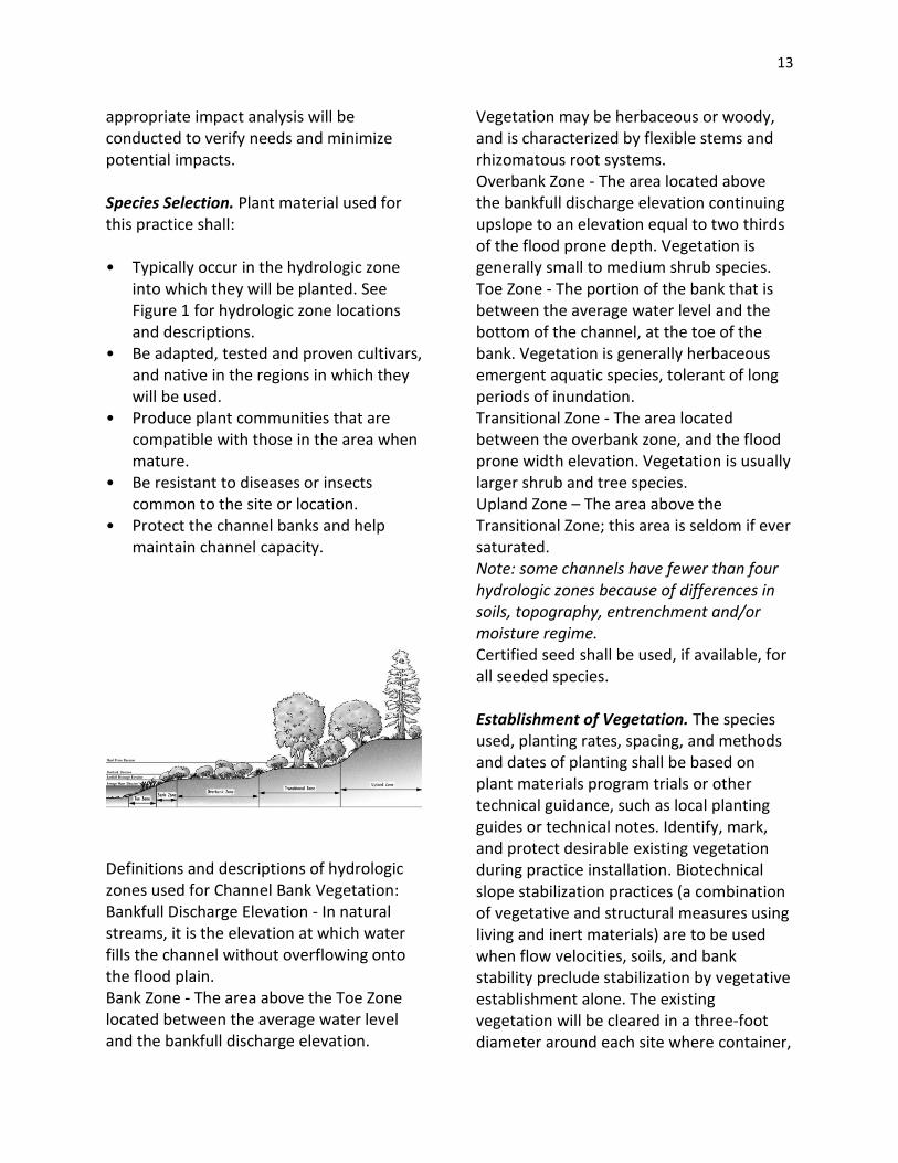
13
appropriate impact analysis will be conducted to verify needs and minimize potential impacts. Species Selection. Plant material used for this practice shall: • Typically occur in the hydrologic zone
into which they will be planted. See Figure 1 for hydrologic zone locations and descriptions.
• Be adapted, tested and proven cultivars, and native in the regions in which they will be used.
• Produce plant communities that are compatible with those in the area when mature.
• Be resistant to diseases or insects common to the site or location.
• Protect the channel banks and help maintain channel capacity.
Definitions and descriptions of hydrologic zones used for Channel Bank Vegetation: Bankfull Discharge Elevation - In natural streams, it is the elevation at which water fills the channel without overflowing onto the flood plain. Bank Zone - The area above the Toe Zone located between the average water level and the bankfull discharge elevation.
Vegetation may be herbaceous or woody, and is characterized by flexible stems and rhizomatous root systems. Overbank Zone - The area located above the bankfull discharge elevation continuing upslope to an elevation equal to two thirds of the flood prone depth. Vegetation is generally small to medium shrub species. Toe Zone - The portion of the bank that is between the average water level and the bottom of the channel, at the toe of the bank. Vegetation is generally herbaceous emergent aquatic species, tolerant of long periods of inundation. Transitional Zone - The area located between the overbank zone, and the flood prone width elevation. Vegetation is usually larger shrub and tree species. Upland Zone – The area above the Transitional Zone; this area is seldom if ever saturated. Note: some channels have fewer than four hydrologic zones because of differences in soils, topography, entrenchment and/or moisture regime. Certified seed shall be used, if available, for all seeded species. Establishment of Vegetation. The species used, planting rates, spacing, and methods and dates of planting shall be based on plant materials program trials or other technical guidance, such as local planting guides or technical notes. Identify, mark, and protect desirable existing vegetation during practice installation. Biotechnical slope stabilization practices (a combination of vegetative and structural measures using living and inert materials) are to be used when flow velocities, soils, and bank stability preclude stabilization by vegetative establishment alone. The existing vegetation will be cleared in a three-foot diameter around each site where container,

14
balled, potted, plug, paper sleeve and bare root stock plantings are planted. A suitable seedbed shall be prepared for all seeded species. Compacted layers will be ripped and the soil re-firmed prior to seedbed preparation. Seeds will be planted using the method or methods best suited to site and soil conditions. Sod placement shall be limited to areas that can naturally supply needed moisture or sites that can be irrigated during the establishment year. Sod will be placed and anchored using techniques to insure that it remains in place during the establishment period. All disturbed areas will be mulched as necessary. Mulch will be applied and anchored according to the criteria in practice standard 484, Mulching. Fertilization. All fertilizers and soil amendments will be applied in accordance with soil analysis and plant requirements, following the criteria in the Nutrient Management standard (code 590). Site Protection and Access Control. Grazing animal access to planted areas will be controlled for a minimum of two growing seasons during the establishment period. All areas to be grazed will have a grazing plan that meets the criteria in practice standard 528, Prescribed Grazing. Grazing shall be permanently excluded on high hazard sites, such as cut banks, areas of seepage or other potentially unstable areas. Tree guards will be placed around landscaped areas as needed to protect against animal damage.
Considerations Stable, overhanging banks that provide shade and cover for fish should not be disturbed. Channel stabilization and streambank protection practices should be considered to facilitate establishment of channel vegetation. A riparian functional assessment should be completed on live streams to determine channel condition. In constructed channels, consider the size of vegetation at maturity so as not to restrict the capacity of the channel or conflict with surrounding uses. Vegetative practices should be designed to provide effective stability and cover. Stability will allow for indigenous vegetation to volunteer on the site. Filter strips, riparian forest buffers and conservation cover applied in conjunction with channel vegetation will improve water quality and enhance wildlife habitat. Providing plant species diversity will help combat disease and the overuse of a single species. Where economically feasible and practical, irrigation of new plantings should be considered. Protection of channel vegetation from upland sediment deposits resulting from wind and water erosion should be considered. Provisions for safety and protection of human life and property should be considered in all aspects of design, application, and maintenance. Consider economic and resource costs of practice failure or re-establishment. Effects of vegetation on water budget components, especially on volumes and peak flows of runoff, should be considered.
15
Techniques to minimize sedimentation impacts from practice installation, such as sediment barriers, erosion control fabric, and biodegradable mulches, should be considered. Effects of woody vegetation on stream temperatures and invertebrate populations should be considered. Plans and Specifications Plans and designs are to be prepared for specific field sites. The plan will identify site conditions, required permits, and include design drawings showing location of planned measures, cut and fill cross sections, requirements for site preparation, location of planned species, planting dates, planting methods, plant spacing, planting depth, mulching, fertilizer and irrigation requirements. A management strategy protecting the site will be in place prior to the installation of Channel Bank Vegetation improvements.
Specifications will be completed for each hydrologic zone located within the channel. Operation and Maintenance Maintenance for this practice includes the following: • Management of vegetative growth, as
applicable, by mowing, prescribed grazing, applying approved pesticides and fertilizer, or other means to maintain the desired cover. Vegetative removal will be restricted to periods having the least impacts on nesting wildlife. All species shall be allowed adequate time for regrowth in order to provide winter cover.
• Repair of appurtenances and fences will be completed as needed.
REFERENCES Bentrup, G., and J.C. Hoag. 1998. The Practical Streambank Bioengineering Guide - User's Guide for Natural Streambank Stabilization Techniques in the Arid and Semiarid Great Basin and Intermountain West. Interagency Riparian/Wetland Plant Development Project. USDA-NRCS, Aberdeen, ID. FISRWG. 1998. Stream Corridor Restoration: Principles, Processes, and Practices. Federal Interagency Stream Restoration Working Group (FISRWG). Hoag, J.C. 1999. Riparian Planting Zones. View from a Wetland, No. 5. (1998-1999) Interagency Riparian/Wetland Project, Plant Materials Center, USDA-NRCS, Aberdeen, ID.
DIVERSION
Definition
A channel constructed across the slope generally with a supporting ridge on the lower side.
Purpose
This practice may be applied as part of a resource management system to support one or more of the

16
following purposes. Break up concentrations of water on long slopes, on undulating land surfaces, and on land that is generally considered too flat or irregular for terracing.
Divert water away from farmsteads, agricultural waste systems, and other improvements.
Increase or decrease the drainage area above ponds.
Protect terrace systems by diverting water from the top terrace where topography, land use, or land ownership prevents terracing the land above.
Intercept surface and shallow subsurface flow.
Reduce runoff damages from upland runoff.
Reduce erosion and runoff on urban or developing areas and at construction or mining sites.
Divert water away from active gullies or critically eroding areas.
Supplement water management on conservation cropping or stripcropping systems.
Conditions Where Practice Applies
This applies to all cropland and other land uses where surface runoff water control and or management is needed. It also applies where soils and topography are such that the diversion can be constructed and a suitable outlet is available or can be provided.
Criteria
Capacity. Diversions as temporary measures, with an expected life span of less than 2 years, shall have a minimum capacity
for the peak discharge from the 2-year frequency, 24-hour duration storm.
Diversions that protect agricultural land shall have a minimum capacity for the peak discharge from a 10-year frequency, 24 -hour duration storm.
Diversions designed to protect areas such as urban areas, buildings, roads, and animal waste management systems shall have a minimum capacity for the peak discharge from a storm frequency consistent with the hazard involved but not less than a 25-year frequency, 24-hour duration storm. Freeboard shall be not less than 0.3 ft.
Design depth is the channel storm flow depth plus freeboard, where required.
Cross section. The channel may be parabolic, V-shaped, or trapezoidal. The diversion shall be designed to have stable side slopes.
The ridge shall have a minimum top width of 4 feet at the design depth. The ridge height shall include an adequate settlement factor (normally 10%).
NRCS, NHFOTG June 2009 Conservation practice standards are reviewed periodically, and updated if needed. To obtain the current version of this standard, contact the Natural Resources Conservation Service. New Hampshire supplement is underlined. 362-2 The ridge top width may be 3 feet at the design depth for diversions with less than 10 acres drainage area above cropland, pastureland, or woodland. The top of the constructed ridge at any point shall not be lower than the design depth plus the specified overfill for settlement.

17
The design depth at culvert crossings shall be the culvert headwater depth for the design storm plus freeboard.
Grade and velocity. Channel grades may be uniform or variable. Channel velocity shall not exceed that considered non-erosive for the soil and planned vegetation or lining.
Maximum channel velocities for permanently vegetated channels shall not exceed those recommended in the NRCS Engineering Field Handbook (EFH) Part 650, Chapter 7, or Agricultural Research Service (ARS) Agricultural Handbook 667, Stability Design of Grass-Lined Open Channels (Sept. 1987).
When the capacity is determined by the formula Q = A V and the V is calculated by using Manning's equation, the highest expected value of "n" shall be used.
Location. The outlet conditions, topography, land use, cultural operations, cultural resources, and soil type shall determine the location of the diversion.
Protection against sedimentation. Diversions normally should not be used below high sediment producing areas. When they are, a practice or combination of practices needed to prevent damaging accumulations of sediment in the channel shall be installed. This may include practices such as land treatment erosion control practices, cultural or tillage practices, vegetated filter strip, or structural measures. Install practices in conjunction with or before the diversion construction.
If movement of sediment into the channel is a problem, the design shall include extra capacity for sediment or periodic removal as outlined in the operation and maintenance plan.
Outlets. Each diversion must have a safe and stable outlet with adequate capacity. The outlet may be a grassed waterway, a lined waterway, a vegetated or paved area, a grade stabilization structure, an underground outlet, a stable watercourse, a sediment basin, or a combination of these practices. The outlet must convey runoff to a point where outflow will not cause damage. Vegetative outlets shall be installed and established before diversion construction to insure establishment of vegetative cover in the outlet channel.
The release rate of an underground outlet, when combined with storage, shall be such that the design storm runoff will not overtop the diversion ridge.
When a level spreader is used as the outlet of the diversion, the length should be one foot per CFS based the 10-year discharge with a minimum length of 5 feet and a maximum length of 30 feet. The entrance channel should not exceed a 1% grade for a minimum of 20 feet before entering level spreader. The outlet must convey runoff to a point where the discharge will not cause damage.
A level spreader shall be constructed on zero percent grade to insure uniform spreading of sediment-free runoff (converting channel flow to sheet flow). Level spreaders should be constructed on undisturbed soil (not on fill). A geotextile erosion stop shall be placed vertically and at least six inches deep in a slit trench one foot in back of the level lip and parallel with the lip. This erosion stop shall extend the entire length of the level lip and after backfilling with tamped soil the geotextile shall be trimmed so that the upper edge is flush with the soil surface. Earthen level lip spreaders shall be protected to resist erosion with two overlapping strips of jute,
18
mesh, or other specified erosion control fabric. The design depth of the water surface in the diversion shall not be lower than the design elevation of the water surface in the outlet at their junction when both are operating at design flow.
Vegetation. Disturbed areas that are not to be cultivated shall be seeded as soon as practicable after construction.
Lining. If the soils or climatic conditions preclude the use of vegetation for erosion protection, non-vegetative linings such as gravel, rock riprap, cellular block, or other approved manufactured lining systems may be used.
NRCS, NHFOTG June 2009 362-3 NRCS, NHFOTG June 2009 Considerations A diversion in a cultivated field should be aligned and spaced from other structures or practices to permit use of modern farming equipment. The side slope lengths should be sized to fit equipment widths when cropped.
At non-cropland sites, consider planting native vegetation in areas disturbed due to construction.
Maximize wetland functions and values with the diversion design. Minimize adverse effects to existing functions and values. Diversion of upland water to prevent entry into a wetland may convert a wetland by changing the hydrology. Any construction activities should minimize disturbance to wildlife habitat. Opportunities should be explored to restore and improve wildlife habitat, including habitat for threatened, endangered, and other species of concern.
On landforms where archeological sites are likely to occur, use techniques to maximize identification of such sites prior to planning, design, and construction.
Plans and Specifications
Plans and specification for installing diversions shall be in keeping with this standard and shall describe the requirements for applying the practice to achieve its intended purpose.
If underground conduits are located under diversion ridges, mechanical compaction or water packing should be required. Installation and backfill of conduit trenches shall be made in advance to allow adequate settlement. Diversion ridges constructed across gullies or depressions shall be compacted sufficiently to keep settlement within tolerable limits.
Topsoil should be stockpiled and spread over excavations and other areas to facilitate revegetation. Follow local standards and recommendations for seeding.
Operation and Maintenance
An operation and maintenance plan shall be prepared for use by the client. The plan shall include specific instructions for maintaining diversion capacity, storage, ridge height, and outlets.
The minimum requirements to be addressed in the operation and maintenance plan are:
Provide periodic inspections, especially immediately following significant storms.
Promptly repair or replace damaged components of the diversion as necessary.

19
Maintain diversion capacity, ridge height, and outlet elevations especially if high sediment yielding areas are in the drainage area above the diversion. Establish necessary clean-out requirements.
Each inlet for underground outlets must be kept clean and sediment buildup redistributed so that the inlet is at the lowest point. Inlets damaged by farm machinery must be replaced or repaired immediately.
Redistribute sediment as necessary to maintain the capacity of the diversion.
Vegetation shall be maintained and trees and brush controlled by hand, chemical and/or mechanical means.
Keep machinery away from steep sloped ridges. Keep equipment operators informed of all potential hazards.
SURFACE DRAINAGE FIELD DITCH Definition A graded ditch for collecting excess water in a field. Purpose To drain surface depressions; collect or intercept excess surface water, such as sheet flow, from natural and graded land surfaces or channel flow from furrows and carry it to an outlet; and collect or intercept excess subsurface water and carry it to an outlet. Condition Where Practice Applies
This standard applies to drainage ditches installed to collect water from a field less than 100 acres per ditch. It does not apply to surface drainage, main or lateral (608) or to grassed waterways or outlets (412). Applicable sites are flat or nearly flat and: • Have soils that are slowly permeable
(low permeability) or that are shallow over barriers, such as rock or clay, which hold or prevent ready percolation of water to a deep stratum.
• Have surface depressions or barriers that trap rainfall.
• Have insufficient land slope for ready movement of runoff across the surface.
• Receive excess runoff or seepage from uplands.
• Require the removal of excess irrigation water.
• Require control of the water table. • Have adequate outlets available for
disposal of drainage water by gravity flow or pumping.
Criteria Drainage field ditches shall be planned as integral parts of a drainage system for the field served and shall collect and intercept water and carry it to an outlet with continuity and without ponding. Compliance with all applicable federal, state and local regulations and ordinances is required. The landowner(s) shall be responsible for obtaining and complying with all applicable permits. Investigations. An adequate investigation shall be made of all sites. Location. Ditches shall be established, insofar as topography and property boundaries permit, in straight or nearly straight courses. Random alignment may be
20
used to follow depressions and isolated wet areas of irregular or undulating topography. Excessive cuts and the creation of small irregular fields shall be avoided. State and locally listed prime and significant wetlands shall be avoided. On extensive areas of uniform topography, collection or interception ditches shall be installed as required for effective drainage. 607 - 2 Design. The size, depth, side slopes, and cross section area shall: • Be adequate to provide the required
drainage for the site. • Permit free entry of water from adjacent
land surfaces without causing excessive erosion.
• Provide effective disposal or reuse of excess irrigation water (if applicable).
• Conduct flow without causing excessive erosion.
• Provide stable side slopes based on soil characteristics.
• Permit crossing by field equipment if feasible.
• Permit construction and maintenance with available equipment. Ditches may be trapezoidal, V-shaped, or parabolic in shape to fit the site conditions. When surface field ditches discharge into ditches of greater depth, the outfall shall be graded back on non-erosive slopes of other protective measures shall be provided.
Channel Vegetation. Vegetation shall be established according to the recommendations in Conservation Practice Standard - 342, Critical Area Planting. Spoil Placement. Spoil material shall be spread and leveled so that the surface
water can flow into the ditch. If the spoil is to be farmed, it shall be spread so that farming operations will not be hindered. Considerations Water Quantity Effects on water budget components,
especially relationships between runoff and infiltration.
The effect of changes in the water table on the rooting depth for anticipated land uses.
Water Quality • Downstream effects of erosion and
yields of sediment and sediment-attached substances.
• Effects on the salinity of the soil in the drained field.
• Effects on the loadings of dissolved substances downstream.
• Potential changes in downstream water temperature.
• Effects on wetlands or other water-related wildlife habitat.
• Effects on the visual quality of downstream water courses.
Plans and Specifications Plans and specifications for constructing drainage field ditches shall be in keeping with this standard and shall describe the requirements for properly installing the practice to achieve its intended purpose. Operation and Maintenance A site-specific operation and maintenance (O&M) plan shall be provided to and reviewed with the landowner(s) before the practice is installed. The plan shall
21
adequately guide the landowner(s) in the routine maintenance and operational needs of the field ditches. The plan shall also include guidance on periodic inspections and post-storm inspections to detect and minimize damage to the drains and outlets.
SUBSURFACE DRAIN
Definition A conduit, such as corrugated plastic tubing, tile, or pipe, installed beneath the ground surface to collect and/or convey drainage water. Purpose The purpose of subsurface drainage is to: • Improve the soil environment for
vegetative growth, reduce erosion, and improve water quality by:
o regulating water table and ground water flows,
o intercepting and preventing water movement into a wet area,
o relieving artesian pressures, o removing surface runoff, o serving as an outlet for other
subsurface drains, and o regulating sub-irrigated areas or
waste disposal areas. Collect ground water for beneficial uses. Remove water from heavy use areas,
such as around buildings, roads, and play areas; and accomplish other physical improvements related to water removal.
Regulate water to control health hazards caused by pests such as live fluke, flies, or mosquitoes.
Conditions Where Practice Applies This practice applies to areas having a high water table where the benefits of lowering the water table or controlling ground water or surface runoff justify installing such a system. This standard applies to areas suitable for the intended use after installation of required drainage and other conservation practices. The soil shall have enough depth and permeability to permit installation of an effective and economically feasible system. In areas where an outlet is available, either by gravity flow or by pumping, the outlet shall be adequate for the quantity and quality of effluent to be discharged. Consideration shall be given to possible damages above or below the point of discharge that might involve legal actions under state or local laws. Consideration shall be given to maintaining or enhancing environmental values. Considerations Subsurface drains are normally used to lower the water table in a certain area, or to serve as an outlet for small detention structures. Installation of drain pipes in less permeable soils may require an envelope of granular drain material to maximize effectiveness. Clogging by tree roots and crushing by vehicular traffic are common causes of drain failures. Where subsurface drains may be subject to these conditions, heavy pipe or other precautions should be considered. Design Criteria
22
General. The planning and design of subsurface drains shall be based on adequate onsite surveys and investigations. Required Capacity. The required capacity shall be determined by applicable drainage coefficient or inflow rate obtained from one or more of the following: • Application of a locally tried and proven
co-efficient. • Experience on similar sites and/or soils. • Onsite measurement, investigation, or
estimates. Application of Darcy's law to lateral or
artesian subsurface flows. Subsurface drains shall be large enough to convey the required capacity to an adequate outlet. The minimum nominal diameter shall be 4 inches. The size of the drain shall be computed using Manning's Formula or design charts in Figures 3 1 and 3 2. Depth, Spacing, and Location. The depth, spacing, and location shall be based on site conditions and be such as to provide adequate drainage for the planned land use. To provide adequate protection of the conduit, the depth of cover over subsurface drains shall not be less than 2.0 feet in mineral soils, or 2.5 feet in organic soils. In organic soils the minimum cover applies after initial subsidence has taken place. Exceptions to the minimum depth of cover may be permitted within 50 feet of the outlet where the conduit is not subject to damage by equipment travel, or through minor depressions within 100 feet of the upstream end of individual or lateral lines.
Minimum Grade. The minimum grades for drains are as follows: Drain Diameter Minimum Grade 4 inches 0.1% 5 inches 0.07% 6 inches or more 0.05% Where subsurface drains are installed in soil that contains a high percentage of silt and very fine sand that may be washed into the drain, the conduit shall be placed on a grade that will result in a minimum velocity of 1.5 ft/sec for design flow, or an approved filter shall be placed around the drain. Maximum Grade Protection. On sites where topographic conditions require the use of drain lines on grades where design velocities will be greater than indicated in the table below, special measures shall be used to protect the conduit. These measures shall be specified for each job based on the particular conditions of the job site. The protective measures shall include one or more of the following: • Wrapping open joints of the pipe or tile
with tar impregnated paper, burlap, or special fabric type filter material.
• Placing the conduit in a sand and gravel envelope or binding with least erodible soil available.
• Sealing joints or using a watertight pipe or non-perforated continuous tubing.
• Enclosing continuous perforated pipe or tubing with fabric type filter material or properly graded sand and gravel.
TABLE 3-1 -- MAXIMUM PERMISSIBLE VELOCITY WITHOUT PROTECTIVE MEASURES

23
USDA Soil Texture Velocity—ft./sec. Sand and Sandy Loam 3.5 Silt and Silt Loam 5.0 Silty Clay Loam 6.0 Clay and Clay Loam 7.0 Coarse Sand .or Gravel 9.0 Materials for Subsurface Drains. Subsurface drains include conduits of concrete, metal, plastic, or other materials of acceptable quality. The conduit shall meet strength and durability requirements of the site Filters and Filter Material. Suitable filters shall be used around conduits where required by site conditions to prevent sediment accumulation in the conduit. The need for a filter shall be determined by the characteristics of the soil materials at drain depth and the velocity of flow in the conduit. Not less than 3 inches of filter material shall surround the conduit when using sand-gravel· filters. The filter shall be designed to prevent the material in which the installation is made from entering the conduit. Not more than 10 percent of the filter shall pass the No. 60 sieve and not more than 5 percent of the filter shall pass the No. 200 sieve. Artificial fabric or mat type filter materials may be used provided the effective opening size, strength, durability, and permeability are adequate to provide constant filtering of the soil to protect subsurface drain
operation throughout the expected life of the system. Envelopes and Envelope Material. Envelopes shall be used around subsurface drains where required for proper bedding of the conduit, or where necessary to improve the characteristics of flow of groundwater into the conduit. Materials used for envelopes do not need to meet the gradation requirements of filters, but they shall not contain materials which will cause an accumulation of sediment in the conduit or render the envelope unsuitable for bedding of the conduit. Envelope 111aterials shall consist of sand-gravel material, all of which shall pass a 1.5 inch sieve, 90 to 100 percent shall' pass a No. 60 sieve, and not more than 5 percent shall pass a No. 200 sieve. Placement and Bedding. All 'subsurface drains, whether flexible conduit such as plastic or bituminized fiber or rigid conduits such as clay or concrete shall be laid to a neat line and grade. The conduit shall be placed and bedded as described in .ASTM F449 "Standard Recommended Practice for Subsurface Installation of Corrugated Thermoplastic Tubing for Agricultural Drainage or Water Table Control". Rigid drainage conduits such as clay or concrete drain tile will not need the 90 degree "V" groove in the trench bottom but all other applicable placement and bedding requirements will be adhered to. Use of Heavy Duty corrugated Plastic Drainage Tubing. Heavy duty corrugated plastic drainage tubing shall be specified where rocky soils are expected to be encountered during installation operations. This quality of tubing will also be specified
24
when cover over the tubing is expected to exceed 10 feet or trench widths are to trench width "in the area of the tubing and at least 1 foot above the top of tubing.) Auxiliary structures and Subsurface Drain Protection. The outlet shall be protected against erosion and undermining of the conduit, entry of tree roots, damaging periods of submergence, and entry of rodents or other animals into the subsurface drain. A 10-foot minimum continuous section of pipe without open joints or perforations shall be used at the outlet end of the line and shall outlet at least 0.5 foot above the normal elevation of low flow in the outlet ditch. Corrugated plastic tubing shall not be used for the outlet section. The pipe and its installation shall conform to the following requirements:
Where there is a hazard of vegetation burning on the outlet ditch bank, the material from which the outlet pipe is fabricated shall be fire resistant. Where the hazard of burning is high, the outlet pipe shall be fireproof.
Two-thirds of the pipe shall be buried in the ditch bank and the cantilevered section shall extend to the toe of the ditch side slope or the side slope shall be protected from erosion. The minimum length of pipe shall be 8 feet.
Where ice or floating debris may damage the outlet pipe, the outlet shall be recessed to the extent that the cantilevered portion of the pipe will be protected from the current in the ditch.
Headwalls which are used for subsurface drain outlets shall be adequate in strength and design to avoid washouts and other failures.
Watertight conduit strong enough to withstand the loads on it shall be used where subsurface drains cross under other ditches. Conduits under roadways shall be designed to withstand the expected loads. Shallow subsurface drains through depressional areas and near outlets shall be protected against hazards of farm and other equipment, and freezing and thawing. Junction boxes shall be used where more than two main lines join. Where surface water is to be admitted to subsurface drains, inlets shall be designed to exclude debris and prevent sediment from entering the conduit. Lines flowing under pressure shall be designed to withstand the resulting pressures and velocity of flow. Auxiliary surface waterways shall be used where feasible. The upper end of each subsurface drain line shall be capped with a tight fitting cap of the sam material as the conduit or other durable material unless connected to a structure. Construction Specifications Inspection and Handling of Materials. Material for subsurface drains shall be given a careful inspection before installation. Clay and concrete tile shall be checked for damage from handling and where applicable from freezing and thawing prior to installation. Bituminized fiber and plastic pipe and tubing shall be protected from hazards causing deformation or warping. Plastic pipe and tubing with physical imperfections shall not be installed. A damaged section shall be removed and a suitable joint made connecting the replaced and retained sections. All material shall be
25
satisfactory for its intended use and shall meet applicable specifications and requirements. Placement. All subsurface drains shall be laid to line and grade and covered with approved blinding, envelope, or filter material to a depth of not less than 3 inches over the top of the drain · If the option to' install an impervious sheet over the drain is used, at ·1east 3 inches of blinding material must cover the sheet. No reversals in grade of the conduit shall be permitted. Where the conduit is to be laid in a rock trench·, or where rock is exposed at the bottom of the trench, the rock shall be removed below grade enough that the trench may be backfilled, compacted, and bedded; and when completed, the conduit shall be not less than 2 inches from rock. Conduit will be placed in such a way that maximum stretch does not exceed 5 percent. Earth backfill material shall be placed in the trench in such a manner that displacement of the conduit will not occur and so that the filter and bedding material, after backfilling, will meet the requirements of the plans and specifications. When a filter is required, all openings in the subsurface drain shall be protected by the filter, or the bottom and sides of the conduit are to be protected by the filter when the top of conduit as well as part of side filter material is to be covered by a sheet of impervious plastic. No portion of the conduit containing openings is to be left exposed under conditions which require the use of a filter. When sand-gravel filter material is used, the trench shall be over-excavated 3 inches
and backfilled to grade with filter material. After placement of the conduit upon the filter material, additional filter material shall be placed over the conduit to fill the trench to a depth of 3 inches over the conduit. A plastic sheet and friable soil can be used in lieu of filter material as the backfill over the subsurface drain when specified. The sand-gravel filter material shall be a unified classification system mixture of sand and gravel within the gradation required by the base material in the trench. During installation and at the end of each day's work, the conduit will be protected from the entrance of soil or other debris. The upper end of each individual subsurface drain shall be blocked with a plug or cap of material of equal strength and durability of that of the conduit. Materials. Subsurface drains include conduits of clay, concrete, bituminized fiber, metal, plastic, or other materials of acceptable quality. The conduit shall meet strength and durability requirements of the site. Drain Chart – Smooth Pipe

26
Drain Chart – Corrugated Pipe
Maintenance Subsurface drains should be checked periodically to see that the outlet pipe of the drain is free flowing. The outlet ditch
should be checked to see that erosion is not taking place. If the subsurface drain has a surface inlet, the inlet should be checked periodically to see that the inlet is not clogged with vegetation or debris. Repairs to the drain should be made promptly.
TERRACE Definition An earth embankment, channel, or a combination ridge and channel constructed across the slope. Purpose Terraces are constructed to (1) reduce a slope length, (2) reduce erosion, (3) reduce sediment content in runoff water, (4) intercept and conduct surface runoff at a non-erosive velocity to a stable outlet, (5) retain runoff for moisture conservation, (6) prevent gully development, (7) reform the land surface, (8) improve farmability, and (9) reduce flooding. An additional purpose of this practice is to maintain or improve water quality. Conditions Where Practice Applies This practice applies where:
Water erosion is a problem.
There is a need to conserve water.
The soils and topography are such that terraces can be constructed and farmed with a reasonable effort.
A suitable outlet can be provided.
Runoff and sediment damages land or improvements downstream or impairs water quality.

27
Considerations
Effects on the water budget, especially on volumes and rates of ·runoff, infiltration, evaporation, transpiration, deep percolation and groundwater recharge.
Variability effects caused by seasonal or climatic changes.
The type of outlet, time of water detention, topography, and geology of the site.
Effects of snow catch and melt on water budget components.
Potential for a change in plant growth and transpiration because of changes in the volume of soil water.
Effects on the downstream flows or aquifers that could affect other water uses and users.
The effect on the water table suitable rooting depth for anticipated land uses.
Potential for water management to Supply alternate uses.
Effects on erosion and the movement of sediment, pathogens, and soluble and sediment-attached substances that would be carried by runoff.
Effects of nutrients and pesticides on surface and groundwater quality.
Effects on the visual quality of on-site and downstream water.
Short-term and construction-related effects on the quality of on-site and downstream water.
Effects on the movement of dissolved substances below the root zone and to the groundwater.
Effects on wetlands and water related wildlife habitats.
Design Criteria
Spacing Terraces for Erosion Control. The maximum spacing shall be determined by one of the following methods, but does not have to be less than 90 feet:
V.I. = o.7s + y or H.I. = (0.7s + y) 100/s Where: V.I. = vertical interval in feet H .I. = horizontal interval in feet s = land slope in feet per 100 feet y = a variable with values from 1.0 to 4.0
Values of y are influenced by soil erodibility, cropping system, and crop management practices. A value of 1.0 should be selected for easily erodible soils with tillage systems that provide little or no cover during periods of intense rainfall. A value of 4.0 should be used for erosion resistant soils with tillage systems that leave a large amount of cover (1.5 tons of straw equivalent) on the surface. A value of 2.5 should be used where one of the above factors is favorable and the other unfavorable. Other values between 1.0 and 4.0 may be used according to the estimated quality of the above factors.
The Universal Soil Loss Equation (USLE) - The spacing shall not exceed the slope length determined for contour cultivation by using the allowable soil loss, the most intensive use planned, and the expected level of management.
The horizontal spacing shall not exceed 450 feet for land slopes up to 2%, 300 feet for land slopes of 2% to 4%, 200 feet for slopes of 4% to 6%, and 150 feet for slopes of 6% and over. These maximum limits may not be exceeded when making adjustments as indicated below. Spacing may be increased as much as 10 percent to provide better

28
alignment or location, to adjust for farm machinery, or to reach a satisfactory outlet. Spacing may be increased an additional 10 percent for terraces with underground outlets. The spacing should be adjusted to provide for an even number of trips for anticipated row crop equipment and maximum opportunity for changing land forming, and erosion should be considered when determining the terrace interval.
Terraces on Noncropland. Maximum spacing will be governed by the capacity requirement. Alignment. Terraces shall be made parallel when feasible and as parallel as practicable in all cases. Curves should be long and gentle to accommodate farm machinery. Land forming, extra cut or fill along the terrace line, multiple outlets, variations in grade, channel blocks, and other methods are to be used to achieve good alignment capacity. The terrace shall have enough capacity to control the runoff from a 10-year frequency, 24-hour storm without overtopping. For terraces with underground outlets, the capacity shall be increased by the estimated 10-year sediment accumulation unless provisions are made to maintain the design capacity through maintenance. Terrace systems designed to provide flood protection or to function with other structures shall have capacity to control a storm of a frequency consistent with the potential hazard involved. When the capacity is determined by the formula Q = AV and the V is calculated by using Manning's formula, an "n" value of 1.6 shall be used. Cross Section. The terrace cross section shall be proportioned to fit the land slope,
the crops grown, and the farm machinery used·. The ridge height shall include a reasonable settlement factor. The ridge shall have a minimum width of 3 feet at the design elevation. The minimum cross sectional area of the terrace channel for gradient terraces shall be 8 square feet for land slopes of 5% or less, 7 square feet for slopes from 5 to 8%, and 6 square feet for slopes steeper than 8%. The opening at the outlet end of terraces shall have a cross section equal to that specified for the terrace channel. Channel Grade. Channel grade shall be determined by one of the following methods:
Maximum channel grade in the lower reaches of the channel should not exceed 0.6 percent.
Maximum channel velocity shall be non-erosive for the soil and planned treatment. Maximum velocity for erosion resistant soils is 2 .5 ft/sec, for average soils 2.0 ft/sec, and for easily erodible soils 1.5 ft/sec.
Velocities are to be computed by. Manning's formula using an "n" value of .03.
Channel grades may be uniform or variable. Channel velocities shall not exceed that which is non-erosive for the soil and planned treatment. For short distances and in upper reaches, channel grades or velocities may be increased to improve alignment.
When terraces have an underground outlet, water and sediment will be ponded in the channel thus reducing velocities and allowing steeper channel grades near the outlet.

29
Minimum grades are to be such that ponding in the channel due to minor irregularities will not cause serious damage to crops or delay in field operations.
Outlets. All terraces must have adequate outlets.
Vegetated outlets may be used for terraces. Such an outlet may be a grassed waterway or vegetated area. The outlet must convey runoff water to a point where the outflow will not cause damage. Outlets are to be installed and vegetated before terrace construction if necessary to provide a stable non-erodible outlet or to insure establishment of vegetative cover. The water surface in the terrace shall not be lower than the water surface in the outlet at their junction when both are operating at design flow.
Underground outlets may be used on terraces. The outlet consists of an intake and underground conduit. An orifice plate, increased in conduit size, or other feature shall be installed in each inlet as needed to control the release rate and prevent ·excessive pressure when more than one terrace discharges into the same conduit. The discharge, when combined with the storage, is to be such that a 10-year frequency, 24-hour storm will not overtop the terrace and growing crops will not be damaged significantly by standing water. The release time shall not exceed 48 hours for the design storm. Shorter periods may be necessary for some crops depending on soil characteristics and water tolerance of crops to be grown.
The underground conduit shall meet the requirements for a subsurface drain. Conduits must be installed deep enough to prevent damage from tillage equipment. The inlet is to consist of a vertical perforated pipe of a material suitable for the intended purpose. The inlet should be located uphill of the front slope of the terrace ridge, if farmed, to permit passage of farm machinery and, where necessary, provide for the anticipated accumulation of sediment and subsequent raising of the terrace ridge. The outlet of the conduit shall have adequate capacity for the design flow without erosion. Blind inlets may be used where they are effective, usually in well drained soils. Combination of different types of outlets may be used on the same system to maximize water conservation and to provide for economical installation of a more farmable system. Vegetation. Steep back slope terraces (and steep front slope, if used) shall be established to grass as soon as practicable after construction. The sod shall be maintained and trees and brush controlled by chemical or mechanical means. Plans and Specifications Plans and specifications for installation of terraces shall be in keeping with this BMWP and shall describe the requirements for application of the practice to achieve its intended purpose. Construction specifications shall be in accordance with the USDA Natural Resources Conservation Service New Hampshire Construction and Materials Specifications for Conservation Engineering Practices.

30
Installation All dead furrows, ditches, or gullies shall be filled prior to construction of the terrace or as part of construction. All old terraces, fencerows, hedgerows, trees, and other obstructions shall be removed as necessary to install a farmable system. The terraces shall be constructed to planned alignment, grade, and cross section, plus the specified overfill for settlement and the channel shall drain reasonably well. Any ditch or depression at the bottom of the back slope should be filled and smoothed so that drainage will be away from the terrace and not parallel to it. Provisions must be made where underground conduits are located under terrace ridges to prevent piping. Mechanical compaction, water packing, installation, and backfill or conduit trenches far enough in advance to allow adequate settlement are methods that can be used. The materials used for the inlet and conduit will be suitable for the purpose intended. Terrace ridges constructed across gullies or depressions shall be compacted by machinery travel or other means sufficient to insure proper functioning of the terrace. The surface of the terrace shall be reasonably smooth and present a satisfactory finish. Where it is necessary, topsoil is to be stockpiled and spread over excavations and other areas to facilitate restoration of productivity. Where vegetation is required, seedbed preparation, seeding, fertilizing and
mulching shall comply with the practice standard for critical area planting. Safety and Maintenance
As part of a conservation plan, a
maintenance program shall be developed to
maintain terrace capacity, storage, ridge
height, and the outlets. Each intake of
underground outlets must be kept clean
and sediment buildup redistributed so the
inlet is in the lowest place. Inlets damaged
or cut off by farm machinery must be
replaced or repaired immediately. If the
practice is on lands without a conservation
plan, a maintenance program will be
described as part of the design.
Terrace ridges, especially those with steep
back slopes, can be very hazardous. For this
reason, some farmers prefer steep· front
slopes also thus keeping machinery away
from the steep back slopes. All cut slopes
and fills that are to be farmed must be no
steeper than that on which farm equipment
can operate safely. Any hazards must be
brought to the attention of the responsible
person.
Land Smoothing
Definition
Removing ruts and other irregularities on
the land surface by use of special
equipment.
Purpose
Improve surface drainage, provide for more
effective use of precipitation, obtain more
uniform planting depths, provide for more
uniform cultivation, improve equipment
operation and efficiency, improve terrace
31
alignment, and facilitate contour
cultivation.
Conditions Where Practice Applies
This practice applies on areas where
depressions, mounds, old terraces, turn
rows, and other surface irregularities
interfere with the application of needed soil
and water conservation and management
practices. It is limited to areas having
adequate soil depth or where topsoil can be
salvaged and replaced.
Considerations
Effects on the water budget, especially
on volumes and rates of runoff,
infiltration, evaporation, transpiration,
deep percolation and groundwater
recharge.
Potential for changes in plant growth
and transpiration because of changes in
the volume of soil water.
Effects on erosion and the movement of
sediment and soluble and sediment-
attached substances carried by runoff.
Effects on the use and management of
nutrients and pesticides.
Effects on downstream water quality.
Effects on the visual quality of
downstream water resources.
Design Criteria
The extent of rough grading required and
tolerances of the finished smoothing job
shall be in keeping with the requirements of
the planned cropping system.
Plans and Specifications
Plans and specifications for land smoothing
shall be in keeping with this BMWP and
shall describe the requirements for applying
the practice to achieve its intended
purpose.
Construction operations shall be carried out
in such a manner that erosion and air and
water pollution are minimized and held
within legal limits.
The land to be smoothed shall be cleared of
vegetative matter and trash.
Irregularities shall be smoothed to the
degree required for the planned use and
the requirements of subsequent tillage,
floating, or planning to be performed.
Where possible, the ground surface should
be plowed or disked prior to smoothing.
At least three passes of a land plane or
leveler should be made over the land to be
smoothed. This should consist of one pass
along each diagonal and the last pass
generally in the direction of cultivation.
Obstruction Removal
Definition
Removal and disposal of unwanted,
unsightly or hazardous buildings, structures,
vegetation, landscape features, trash, and
other materials.
Purpose
To safely remove and dispose of unwanted
obstructions and materials in order to apply
conservation practices or facilitate planned
use of abandoned mine lands, farms,
32
ranches, construction sites, and recreation
areas.
Conditions Where Practice Applies
On land where existing obstructions
interfere with planned use and
development.
Considerations
Effects upon components of the water
budget, especially effects on volume
and rate of runoff, infiltration,
evaporation, transpiration, deep
percolation, and groundwater recharge.
Effects on the visual quality or
downstream water resources.
Short-term and construction-related
effects on the quality of water
resources.
Design Criteria
Rock piles, boulders, stones, fences, hedge
rows, abandoned buildings and structures,
trash, and similar obstructions that would
interfere with planned use and
.development shall be removed. All debris
such as broken concrete and masonry,
structural steel and wood, stones, stumps,
slash, and sterile or toxic soil material shall
be disposed of so that they will not impede
subsequent work or cause damage to off
site or other areas. Disposal shall be by
burning, burying, or removing to an
approved land fill in an environmentally
acceptable manner. All required gully
shaping shall be performed to specified
dimensions and grades. Gully fills shall be
compacted to the required density. The
cover over buried materials shall be
designed to be adequate for the planned
use, treatment, and vegetation. Historical
or archeological significant and scenic
values shall be identified and preserved as
appropriate.
Plans and Specifications
Plans and specifications for obstruction
removal shall be in keeping with this BMWP
and shall describe the requirements for
applying and achieving the practice
purpose.
UNDERGROUND OUTLET
Definition
A conduit installed beneath the surface of
the ground to collect surface water and
convey it to a suitable outlet.
Purpose
To dispose of excess water from terraces,
diversions, subsurface drains, surface
drains, trickle tubes or principal spillways
from dams (outside the dam area only), or
other concentrations without causing
damage by erosion or flooding.
Conditions Where Practice Applies
This practice applies where: (1) excessive
surface water needs to be disposed of; (2) a
buried outlet is needed for diversions,
terraces, or similar practices; (3) an
underground outlet can be installed that
will safely dispose of excess water; and (4)
surface outlets are impractical because of
stability problems, climatic conditions, land
use, or equipment traffic.
Considerations
33
Consider effects on the water budget,
especially on volumes and rates of
runoff, infiltration, evaporation,
transpiration, deep percolation, and
groundwater recharge.
Consider effects on the - volume of
downstream flow that might cause
undesirable environmental, social, or
economic effects.
Evaluate potential use for water
management.
Consider effects on erosion and the
movement of sediment, pathogens, and
soluble and sediment-attached
substances that would be carried by
runoff.
Consider effects on the visual quality of
downstream water resources.
Consider sediment-attached and
construction-related effects on the
quality of downstream water courses.
Consider effects on wetlands or water-
related wildlife habitats.
Design Criteria
Capacity. The underground outlet shall be
designed, alone or in combination with
other practices, with adequate capacity to
insure that the terrace, diversion or other
practices function according to the standard
for the specific practice. For example, an
underground outlet can be used in
combination with a grassed waterway or a
surface drain to carry part of the design
flow. The capacity of the underground
outlet for natural basins shall be adequate
for the intended purpose without causing
excessive damage to crops, vegetation, or
improvements.
Inlet. An inlet can be a collection box, a
perforated riser, or other appropriate
device. Its capacity shall be adequate to
provide the maximum design flow in the
conduit. Flow-control devices shall be
installed as necessary. Perforated risers
must be of durable material, structurally
sound and resistant to damage by rodents
or other animals. If burning of vegetation is
likely to create a fire hazard, the inlet shall
be fire resistant. Blind inlets can be used
where they are effective. Collection boxes
must be large enough to facilitate
maintenance and cleaning operations. The
inlet must have an appropriate trash guard
to insure that trash or other debris entering
the inlet passes through the conduit
without plugging. It must also have an
animal guard to prevent the entry of
rodents or other animals.
Pressure-relief wells hall be designed and
installed if needed to control pressure. If
junction boxes and other structures are
needed, they shall be designed and installed
in a manner that facilitates cleaning and
other maintenance activities.
Hydraulics. Underground outlets shall be
continuous conduits, tubing, or tile. Joints
shall be hydraulically smooth, and the
materials and methods used shall be
recommended by the manufacturer. If a
pressure system is used, joints shall be
adequate to withstand the design pressure,
including surges and vacuum. The maximum
velocity must not exceed the safe velocity
for the conduit materials and installation.
Lines shall be adequate to carry the design
flow when the outlet and all inlets are
operating at design capacity. Capacity shall
34
be based on the pipe size or on other flow
control devices to prevent water from the
upper inlets from discharging through the
lower inlets. The minimum conduit
diameter shall be 3 inches.
Materials shall meet or exceed the design
requirements against leakage and shall
withstand internal pressure or vacuum and
external loading. Plastic, concrete,
aluminum, and steel shall meet the
requirements specified in the applicable
ASTM standard.
All materials specified for subsurface drains
can be used for underground outlets.
Conduits, however, can be perforated or
nonperforated, depending on the design
requirements.
Outlet. The outlet shall be sufficiently stable
for all anticipated flow conditions. It shall
be designed for the maximum anticipated
water surface at design flow. A continuous
section of closed conduit or a headwall can
be used at the outlet. If a closed conduit is
used, it shall be durable and strong enough
to withstand all anticipated loads, including
those caused by ice. If fire is a hazard, the
outlet shall be fire resistant. All outlets near
ponds, outlet channels, or streams where
water is normally present must have animal
guards to prevent the entry of rodents or
other animals. Animal guards must be
hinged to allow passage of debris.
Protection. Before the outlet is installed, all
disturbed areas shall be reshaped and
regraded so that they blend with the
surrounding land features and conditions.
Visual resources must be given the same
consideration as other design features.
Areas that are not to be farmed or covered
by structural works shall be established to
vegetation or otherwise protected from
erosion as soon as practicable after
construction.
Maintenance. Underground outlets shall be
maintained by keeping inlets, trash guards,
and collection boxes and structures clean
and free of materials that can reduce the
flow. All leaks shall be repaired promptly to
insure proper functioning of the conduit.
Animal guards must be inspected
periodically and maintained in proper
working order.
Plans and Specifications
Plans and specifications for installing
underground outlets shall be in keeping
with this BMWP and shall describe the
requirements for installing the practice to
achieve its intended purpose.

35
CHAPTER IV
PONDS, WATER SUPPLY AND IRRIGATION
Intent
The intent when using these practices is to avoid wetlands if possible and if not to minimize
impacts to the wetlands by protecting characteristics, functions and values. Typically the
wetlands affected by these practices are classified as Wet Meadow, and occur in an agricultural
field and have hydric soils that are defined as soils that, in an undrained condition, are
saturated, flooded, or ponded long enough during a growing season to develop an anaerobic
condition that supports the growth and regeneration of hydrophytic vegetation. Additional
jurisdictional wetland areas may include forested wetlands, intermittent stream, farm ponds
or other areas that support and are necessary to an existing agricultural operation.
POND
Definition
A water impoundment made by
constructing a dam or an embankment or
by excavating a pit or dugout.
In this practice, ponds constructed by the
first method are referred to as
embankment ponds and those constructed
by the second method as excavated ponds.
Ponds constructed by both the excavation
and the embankment methods are
classified as embankment ponds if the
depth of water impoundment against the
embankment at spillway elevation is 3 feet
or more.
Purpose
To provide water for livestock, fish and
wildlife, recreation, fire control, crop and
orchard spraying, and other related issues.
Conditions Where Practice Applies
Site conditions. Site conditions shall be of
such that runoff from the design storm can
be safely passed through: (1) a natural or
constructed emergency spillway; (2) a
combination of a principal spillway and an
emergency spillway; or (3) a principal
spillway.
Drainage area. The drainage area above
the pond must be protected against erosion
to the extent that expected sedimentation
will not shorten the planned effective life of
the structure. The drainage area shall be
large enough so that surface runoff and
groundwater flow will maintain an
adequate supply of water in the pond. The
water quality shall be suitable for its
intended use.
Reservoir area. The topography and soils of
the site shall permit storage of water at a
depth and volume that insures a
dependable supply, considering beneficial
use, sedimentation, season of use, and
evaporation and seepage losses. If surface
runoff is the primary source of water for a
pond, the soils shall be impervious enough
to prevent excessive seepage losses or shall
be of a type that sealing is practicable.
36
Considerations
Recommended Pond Size. A stockwater pond shall provide 20 to 30 gallons per cow per day, or 20 cubic yards of water per cow per year with no inflow, or 1500 gallons per day (enough for 72 cows). A fire protection pond shall provide storage of 100,000 gallons between two feet below full elevation and two feet above the bottom elevation. Check local fire departments and insurance regulations. Refer to the appropriate standard in the NH Field Office Technical Guide for Wildlife pond size criteria. This BMWP establishes the minimum
acceptable quality for the design and
construction of ponds if:
Failure of the dam will not result in loss
of life; in damage to homes, commercial
or industrial buildings, main highways,
or railroads; or in interruption of the use
or service of public utilities.
The product of the storage times the
effective height of the dam is less than
3,000. Storage is the volume, in acre-
feet, in the reservoir below the
elevation of the crest of the emergency
spillway. The effective height of the dam
is the difference in elevation, in feet,
between the emergency spillway crest
and the lowest point in the cross section
taken along the centerline of the dam. If
there is no emergency spillway, the top
of the dam is the upper limit.
The effective height of the dam is 6 feet
or less, and the dam is hazard class A.
Drainage area is 640 acres or less.
The following are considerations for water
quantity and quality.
Effects upon components of the water
budget, especially effects on volumes
and rates of runoff, infiltration,
evaporation, transpiration, deep
percolation, and groundwater recharge.
Variability of effects caused by seasonal
or climatic changes.
Effects on the downstream flows or
aquifers that could affect other water
uses or users.
Potential for multiple use.
Effects on the volume of downstream
flow to prohibit undesirable
environmental, social, or economic
effects.
Effects on erosion and the movement of
sediment, pathogens, and soluble and
sediment attached substances that are
carried by runoff.
Effects on the visual quality of onsite
and downstream water resources.
Short-term and construction-related
effects of this practice on the quality of
downstream water courses.
Effects of water level control on the
temperatures of downstream waters to
prevent undesired effects on aquatic
and wildlife communities.
Effects on wetlands and water-related
wildlife habitats.
Effects of water levels on soil nutrient
processes such as plant nitrogen use or
denitrification.
37
Design Criteria for Embankment Ponds
Permit. A dam permit is required
from the New Hampshire Department of
Environmental Services Water Resources
Division for 2 acre-feet or more of
impoundment or an embankment height of
6 feet or greater.
Fencing. All stockwater ponds shall be
fenced where cattle will have access to the
pond area. Where the pond cannot supply a
stockwater tank by gravity flow, a watering
ramp of adequate width (no less the 12
feet) shall be provided. The ramp shall
extend from the permanent water line to
the anticipated low water elevation at a
slope not steeper than 4 horizontal to 1
vertical.
Foundation cutoff. A cutoff of relatively
impervious material shall be provided under
the dam if necessary. The cutoff shall be
located at or upstream from the centerline
of the dam. It shall extend up to the
abutments as required and be deep enough
to extend into a relatively impervious layer
or provide for a stable dam when combined
with seepage control. The cutoff trench
shall have a bottom width adequate to
accommodate the equipment used for
excavation, backfill, and compaction
operations, and side slopes shall not be
steeper than 1:1.
Seepage control. Seepage control is to be
included if (1) pervious layers are not
intercepted by the cutoff, (2) seepage may
create swamping downstream, (3) needed
to insure a stable embankment, or (4)
special problems require drainage for a
stable dam. Seepage control may be
accomplished by (1) foundation, abutment,
or embankment drains, (2) reservoir
.blanketing, or (3) a combination of these
measures.
Earth embankment. The minimum top
width for a dam is shown below. If the
embankment top is to be used as a public
road, the minimum width shall be 16 feet
for one-way traffic and 26 feet for two-way
traffic. Guardrails or other safety measures
shall be used where necessary and shall
meet the requirements of the responsible
road authority.
For this BMWP, the maximum effective
height of the dam is 6 feet.
The combined upstream and downstream
side slopes of the settled embankments
shall not be less than 5 horizontal to 1
vertical, and neither slope steeper than 2:1.
All slopes must be designed to be stable.
If needed to protect the face of the dam,
special measures, such as berms, rock
riprap, sand-gravel, soil cement, or special
vegetation, shall be provided.
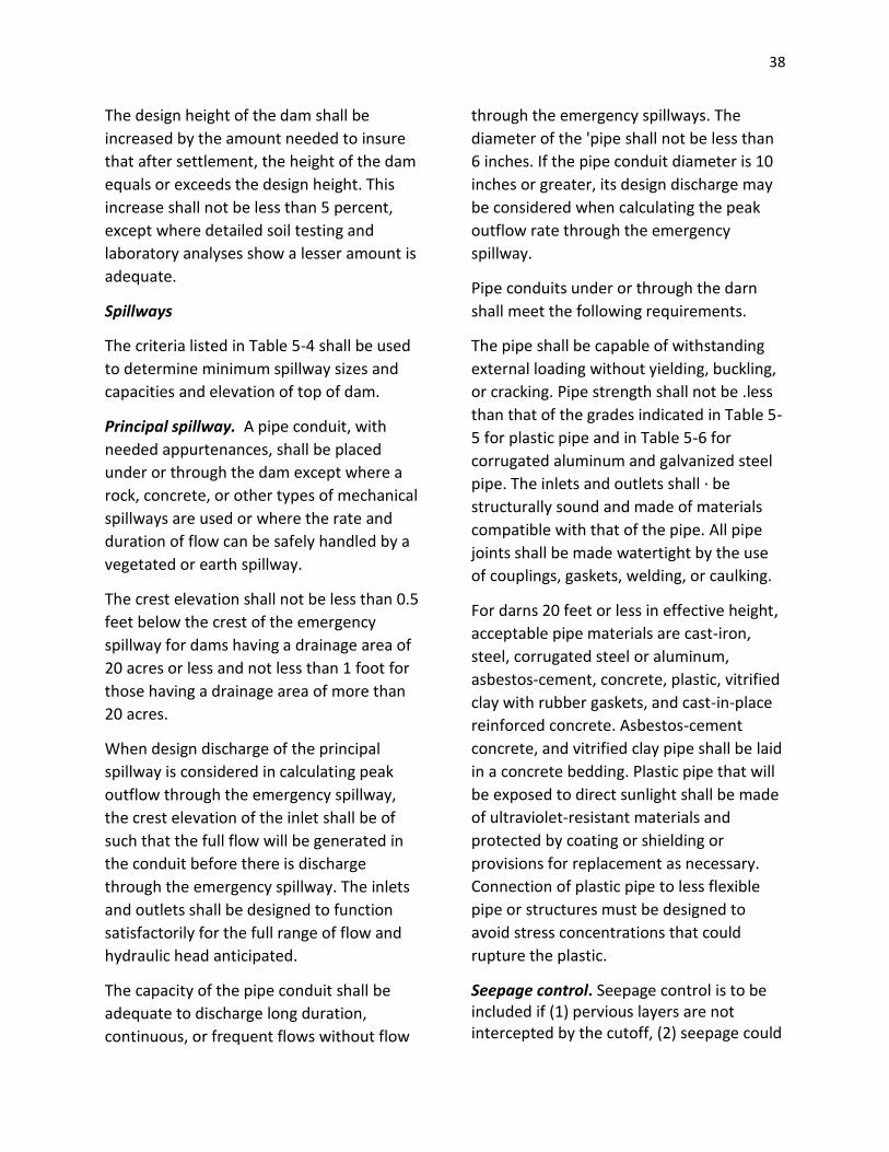
38
The design height of the dam shall be
increased by the amount needed to insure
that after settlement, the height of the dam
equals or exceeds the design height. This
increase shall not be less than 5 percent,
except where detailed soil testing and
laboratory analyses show a lesser amount is
adequate.
Spillways
The criteria listed in Table 5-4 shall be used
to determine minimum spillway sizes and
capacities and elevation of top of dam.
Principal spillway. A pipe conduit, with
needed appurtenances, shall be placed
under or through the dam except where a
rock, concrete, or other types of mechanical
spillways are used or where the rate and
duration of flow can be safely handled by a
vegetated or earth spillway.
The crest elevation shall not be less than 0.5
feet below the crest of the emergency
spillway for dams having a drainage area of
20 acres or less and not less than 1 foot for
those having a drainage area of more than
20 acres.
When design discharge of the principal
spillway is considered in calculating peak
outflow through the emergency spillway,
the crest elevation of the inlet shall be of
such that the full flow will be generated in
the conduit before there is discharge
through the emergency spillway. The inlets
and outlets shall be designed to function
satisfactorily for the full range of flow and
hydraulic head anticipated.
The capacity of the pipe conduit shall be
adequate to discharge long duration,
continuous, or frequent flows without flow
through the emergency spillways. The
diameter of the 'pipe shall not be less than
6 inches. If the pipe conduit diameter is 10
inches or greater, its design discharge may
be considered when calculating the peak
outflow rate through the emergency
spillway.
Pipe conduits under or through the darn
shall meet the following requirements.
The pipe shall be capable of withstanding
external loading without yielding, buckling,
or cracking. Pipe strength shall not be .less
than that of the grades indicated in Table 5-
5 for plastic pipe and in Table 5-6 for
corrugated aluminum and galvanized steel
pipe. The inlets and outlets shall · be
structurally sound and made of materials
compatible with that of the pipe. All pipe
joints shall be made watertight by the use
of couplings, gaskets, welding, or caulking.
For darns 20 feet or less in effective height,
acceptable pipe materials are cast-iron,
steel, corrugated steel or aluminum,
asbestos-cement, concrete, plastic, vitrified
clay with rubber gaskets, and cast-in-place
reinforced concrete. Asbestos-cement
concrete, and vitrified clay pipe shall be laid
in a concrete bedding. Plastic pipe that will
be exposed to direct sunlight shall be made
of ultraviolet-resistant materials and
protected by coating or shielding or
provisions for replacement as necessary.
Connection of plastic pipe to less flexible
pipe or structures must be designed to
avoid stress concentrations that could
rupture the plastic.
Seepage control. Seepage control is to be included if (1) pervious layers are not intercepted by the cutoff, (2) seepage could
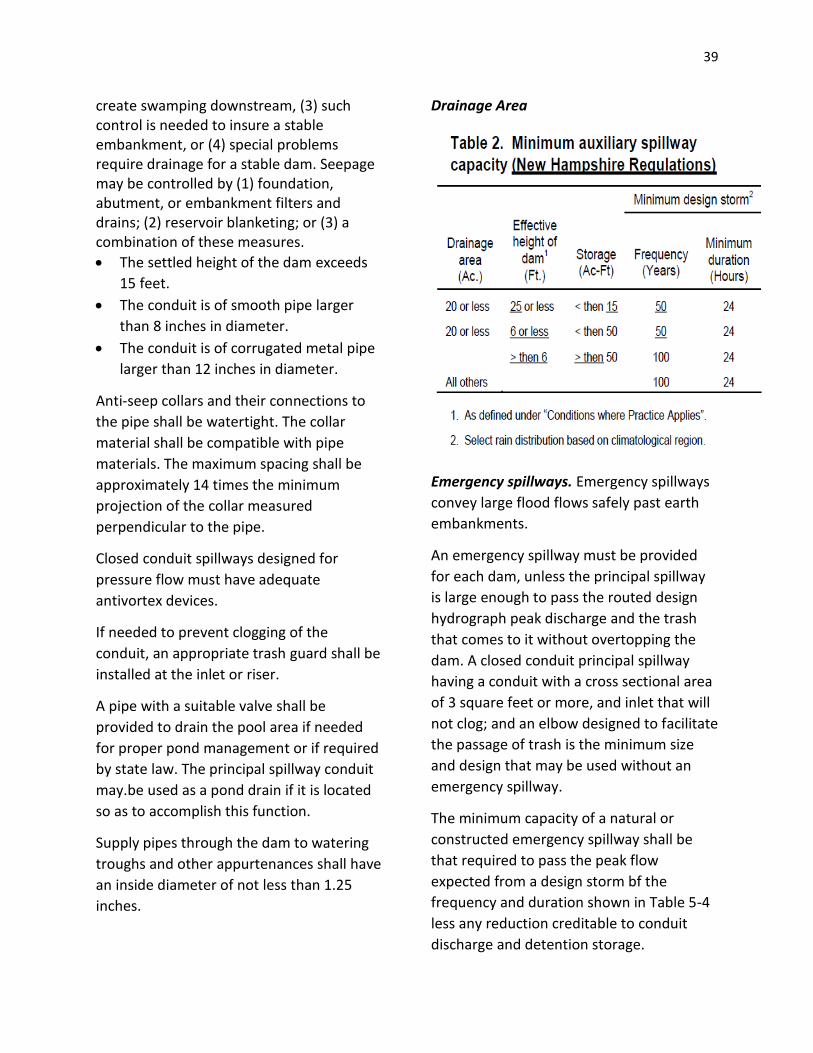
39
create swamping downstream, (3) such control is needed to insure a stable embankment, or (4) special problems require drainage for a stable dam. Seepage may be controlled by (1) foundation, abutment, or embankment filters and drains; (2) reservoir blanketing; or (3) a combination of these measures.
The settled height of the dam exceeds
15 feet.
The conduit is of smooth pipe larger
than 8 inches in diameter.
The conduit is of corrugated metal pipe
larger than 12 inches in diameter.
Anti-seep collars and their connections to
the pipe shall be watertight. The collar
material shall be compatible with pipe
materials. The maximum spacing shall be
approximately 14 times the minimum
projection of the collar measured
perpendicular to the pipe.
Closed conduit spillways designed for
pressure flow must have adequate
antivortex devices.
If needed to prevent clogging of the
conduit, an appropriate trash guard shall be
installed at the inlet or riser.
A pipe with a suitable valve shall be
provided to drain the pool area if needed
for proper pond management or if required
by state law. The principal spillway conduit
may.be used as a pond drain if it is located
so as to accomplish this function.
Supply pipes through the dam to watering
troughs and other appurtenances shall have
an inside diameter of not less than 1.25
inches.
Drainage Area
Emergency spillways. Emergency spillways
convey large flood flows safely past earth
embankments.
An emergency spillway must be provided
for each dam, unless the principal spillway
is large enough to pass the routed design
hydrograph peak discharge and the trash
that comes to it without overtopping the
dam. A closed conduit principal spillway
having a conduit with a cross sectional area
of 3 square feet or more, and inlet that will
not clog; and an elbow designed to facilitate
the passage of trash is the minimum size
and design that may be used without an
emergency spillway.
The minimum capacity of a natural or
constructed emergency spillway shall be
that required to pass the peak flow
expected from a design storm bf the
frequency and duration shown in Table 5-4
less any reduction creditable to conduit
discharge and detention storage.

40
The emergency spillway shall safely pass the
peak flow or the storm runoff shall be
routed through the reservoir. The routing
shall start with the water surface at the
elevation of the crest of the principal
spillway or at the water surface after 10
days drawdown, whichever is higher. The
10-day drawdown shall be computed from
the crest of the emergency spillway or from
the elevation that would be attained if 1 the
entire design storm were impounded,
whichever is lower. Emergency spillways
shall provide for passage of the design flow
at a safe velocity to a point downstream
where the dam will not be endangered.
Constructed spillways shall be trapezoidal
and shall be located in undisturbed or
compacted earth. The side slopes shall be
stable for the material in which the spillway
is to be constructed.
Constructed spillways are open channels
and usually consist of an inlet channel, a
control section, and an exit channel.
Upstream from the control section the inlet
channel shall be level for the distance
needed to protect and maintain the crest
elevation of the spillway. The inlet channel
may be curved to fit existing topography.
The grade of the exit channel of a
constructed spillway shall fall within the
range established by discharge
requirements and permissible velocities.
Structural emergency spillways. If chutes or
drops are used for principal spillways or
principal emergency or emergency
spillways, they shall be designed to the
principles set forth in the USDA Natural
Resources Conservation Service Engineering
Field Handbook, National Engineering
Handbook, Section 5, Hydraulics, Section
11, Drop Spillways, and Section 14, Chute
Spillways. The minimum capacity of a
structural· spillway shall be that required to
pass the peak flow expected from a design
storm of the frequency and duration shown
in Table 5-4 less any reduction creditable to
conduit discharge and detention storage.
Visual resource design. The visual design of
ponds in areas of high public visibility and
those associated with recreational shall be
carefully considered. The underlying
criterion for all visual design is
appropriateness. The shape and form of
ponds, excavated material, and plantings
are related visually to their surroundings
and to their function.
The embankment may be shaped to blend
with the natural topography. The edge of
the pond may be shaped so that it is
generally curvilinear rather than
rectangular. Excavated material can be
shaped so that the final form is smooth,
flowing, and fitting to the adjacent
landscape rather than angular geometric
mounds. If feasible, islands may be added
for visual interest and wildlife value.
Design Criteria for Excavated Ponds
Runoff. Provisions shall be made for a pipe
and emergency spillway if necessary. Runoff
flow patterns shall be considered when
locating the pit and placing the spoil.
Side slopes. Side slopes of excavated ponds
shall be stable and shall not be steeper than
1 horizontal to 1 vertical. If livestock water
directly from the pond, a watering ramp of
ample width shall be provided. The ramp

41
shall extend to the anticipated low water
elevation at a slope no steeper than 3:1.
Perimeter form. If the structures are to be
used for recreation or are located in high
public view, the perimeter or edge must be
curvilinear in form.
Inlet protection. If surface water enters the
pond in a natural or excavated channel, the
side slope of the pond shall be protected
against erosion.
Excavated material. The material
excavated from the pond shall be placed so
that its weight will not endanger the
stability of the pond side slopes and where
it will not be washed back into the pond by
rainfall. It shall be disposed of in one of the
following ways:
Uniformly spread to a height not
exceeding 3 feet with the top graded to
a continuous slope away from the pond;
Uniformly placed or shaped reasonably
well with side slopes assuming a natural
angle of repose for the excavated
material behind a berm width equal to
the depth of the pond, but not less than
12 feet;
Shaped to a designed form that blends
visually with the landscape;
Used for low embankment and leveling;
or
Hauled away.
Plans and Specifications
Plans and specifications for installing ponds
shall be in keeping with this BMWP and
shall describe the requirements for applying
the practice to achieve its intended
purpose.
Foundation preparation. The foundation
area shall be cleared of trees, logs, stumps,
roots, brush, boulders, sod, and rubbish. If
needed to establish vegetation, the topsoil
and sod shall be stockpiled and spread on
the completed dam and spillways.
Foundation surfaces shall be sloped no
steeper than 1:1. The foundation area shall
be thoroughly scarified before placement of
the material. The surface shall have
moisture added or it shall be compacted if
necessary so that the first layer of fill
material can be compacted and bonded to
the foundations.
The cutoff trench and any other required
excavations shall be dug to the lines and
grades shown on the plans or as staked in
the field. If they are suitable, excavated
materials shall be used in the permanent
fill.
Existing stream channels in the foundation
area shall be sloped no steeper than 1:1
and deepened and widened as necessary to
remove all stones, gravel, sand, stumps,
roots, and other objectionable material and
to accommodate compaction equipment.
Foundation areas shall be kept free of
standing water when fill is being placed on
them.
Fill placement. The material placed in the
fill shall be free of detrimental amounts of
sod, roots, frozen soil, stones more than 6
inches in diameter (except for rock fills),
and other objectionable material.
Selected backfill material shall be placed
around structures, pipe conduits, and anti-
seep collars at about the same rate on all

42
sides to prevent damage from unequal
loading.
The placing and spreading of fill material
shall be started at the lowest point of the
foundation and the fill brought up in
horizontal layers of such thickness that the
required compaction can be obtained. The
fill shall be constructed in continuous
horizontal layers except where openings or
sectionalized fills are required. In those
cases, the slope of the bonding surfaces
between the embankment in place and the
embankment to be placed shall not be
steeper than 3:1. The bonding surface shall
be treated the same as that specified for
the foundation so as to insure a good bond
with the new fill.
The distribution and gradation of .materials
shall be of such that no lenses, pockets,
streaks, or layers of material differ
substantially in texture of gradation from
the surrounding material. If it is necessary
to use materials of varying texture and
gradation, the more impervious material
shall be placed in the center and upstream
parts of the fill. If zoned fills of substantially
differing materials are specified, the zones
shall be placed according to lines and
grades shown on the drawings. The
complete work shall conform to the lines,
grades, and elevations shown on the
drawings or as staked in the field.
Moisture control. The moisture content of
the fill material shall be adequate for
obtaining the required compaction.
Material that is too wet shall be dried to
meet this requirement, and material that is
too dry shall have water added and mixed
until the requirement is met.
Compaction. Construction equipment shall
be operated over the are.as or each layer of
fill to insure that the required compaction is
obtained. Special equipment shall be used if
needed to obtain the required compaction.
If a minimum required density is specified,
each layer of fill shall be compacted as
necessary to obtain that density.
Fill adjacent to structures, pipe conduits,
and anti-seep collars shall be compacted to
a density equivalent to that of the
surrounding fill by means of hand tamping
or manually directed power tampers or
plate vibrators. Fill adjacent to concrete
structures shall not be compacted until the
concrete is strong enough to support the
load.
Protection. A protective cover of vegetation
shall be established on all exposed surfaces
of the embankment, spillway, and borrow
area if soil and climatic conditions permit. If
soil or climatic conditions preclude the use
of vegetation and protection is needed,
non-vegetative means, such as mulches or
gravel, may be used. In some places,
temporary vegetation may be used until
conditions permit establishment of
permanent vegetation. The embankment
and spillway shall be fences if necessary to
protect the vegetation.
Seedbed preparation, seeding, fertilizing,
and mulching shall comply with instructions
in technical guides.
Principal spillway. Corrugated metal pipe
shall conform to the requirements of
Federal Specifications WW-P-402 or WW-P-
405, as appropriate. Other pipe materials
shall conform to specifications suitable for

43
the intended purpose. Anti-seep collars
shall be of materials compatible with that of
the pipe and shall be installed so that they
are watertight. The pipe shall be installed
according to the manufacturer's
instructions. The pipe shall be firmly and
uniformly bedded throughout its length and
shall be installed to the line and grade
shown on the drawings.
Concrete. The mix design and testing of
concrete shall be consistent with the sand
and requirements of the job. Mix
requirements or necessary strength shall be
specified. The type of cement, air
entrainment, slump, aggregate, or other
properties shall be specified if necessary. All
concrete is to consist of a workable mix that
can be placed and finished in an acceptable
manner. Necessary curing shall be specified.
Reinforcing steel shall be placed as
indicated on the plans and shall be held
securely in place during concrete
placement. Subgrades and forms shall be
installed to line and grade, and the forms
shall be mortar tight and yielding as the
concrete is placed.
Foundation and embankment drains.
Foundation and embankment drains, if
required, shall be placed to the line and
grade shown of the drawings. Detailed
requirements for drain material and any
required pipe shall be shown in the
drawings and specifications for the job.
Excavated ponds. The completed
excavation shall conform to the lines,
grades, and elevations shown on the
drawings or as staked in the field.
Embankment and excavated ponds.
Construction operations shall be carried out
in such a manner and sequence that erosion
and air and water pollution are minimized
and held within legal limits. All work shall
be conducted in a skillful and professional
manner. The completed job shall present a
good appearance.
Measures and construction methods that
enhance fish and wildlife values shall be
incorporated as needed and practical.
Fencing and cover to control erosion and
pollution shall be established as needed.
Appropriate safety measures, such as
warning signs, rescue facilities, and fencing,
shall be provided.
Operation and Maintenance
An operation and maintenance plan shall be
developed and reviewed with the
landowner or individual responsible for
operation and maintenance.
Irrigation Storage Reservoir
Definition
A small storage reservoir constructed to
regulate or store a supply of water for
irrigation.
Purpose
To collect and store water until it can be
used beneficially to satisfy crop irrigation
requirements.
Conditions Where Practice Applies
This practice applies only to sites meeting
all the following criteria and conditions:
The existing water supply available to
the irrigated area is insufficient to meet

44
conservation Irrigation requirements
during part or all the irrigation season;
Construction of an irrigation pit is the
most practical means of obtaining a
needed additional supply of water;
An adequate supply of good quality
water is available for storage from
surface runoff, streamflow, or from a
subsurface source;
Topographic, geologic 1 water table,
and soils conditions at the site. are
satisfactory for the feasible
development of the irrigation pit; and
If surface runoff enters the pit, the
contributing drainage area is or can be
protected against erosion so that
normal sedimentation dos not
materially shorten the planned life of
the pit.
Considerations
Effects on the water budget, especially
on volumes and rates of runoff,
infiltration, evaporation, transpiration,
deep percolation, and groundwater
recharge.
Effects on downstream flows or aquifers
that would affect other water uses or
users.
Potential for irrigation water
management.
Effects on erosion and the movement of
sediment, pathogens, and the soluble
and sediment attached substances
carried by runoff.
Effects on the movement of dissolved
substances to groundwater.
Short-term and construction-related
effects on the quality of downstream
water courses.
Potential for uncovering or
redistributing toxic material.
Effects on wetlands or water-related
wildlife habitats.
Effects on the visual quality of water
resources.
Design Criteria
Capacity. Irrigation storage reservoirs shall
be designed to have a usable capacity
sufficient to satisfy irrigation requirements
in the design area throughout the growing
season of the crop or crops being irrigated.
In computing capacity requirements, due
consideration shall be given, where
applicable, to groundwater inflow, surface
runoff, precipitation, evaporation, and
seepage. Additional capacity shall be
provided as necessary for sediment storage.
The usable capacity of a pit that depends
wholly on groundwater as a source of
supply shall be that part of the pit that is
below the static water level.
Reservoir design. Irrigation reservoirs shall
be designed according to the criteria for
excavated Pond Best Management
Wetlands Practice for Agriculture.
Outlet works. Suitable outlet works shall be
provided for the controlled release of
irrigation water. The capacity of the outlet
works shall be no less than that required to
provide the outflow rate needed to meet
peak period irrigation system demands.
Plans and Specifications
Plans and specifications for irrigation pits
shall be in keeping with this BMWP and
shall describe the requirements for properly
installing the practice to achieve its

45
intended purpose. Irrigation pits shall be
constructed according to the Pond Best
Management Wetlands Practice for
Agriculture.
Dike
Definition
An embankment constructed of earth or
other suitable materials to protect land
against overfiow or to regulate water.
Purpose
To permit improvement of agricultural land
by preventing overflow and better use of
drainage facilities, to prevent damage to
land and property, and to facilitate water
storage and control in connection with
wildlife and other developments. Dikes can
also be used to protect natural areas, scenic
features, and archeological sites from
damage.
Conditions Where Practice Applies
Class I dikes are those constructed on sites
where:
Failure may cause loss of life or serious
damage to homes, industrial and
commercial buildings, important public
utilities, main highways or railroads, and
high value land, crops, or other
improvements.
Unusual or complex site conditions
require special construction procedures
to ensure satisfactory installations.
Protection is needed to withstand more
than 12 feet of water above normal
ground surface, exclusive of crossings of
sloughs, old channels, or low areas.
Class II dikes are those constructed in highly
developed and productive agricultural areas
where:
Failure may damage isolated names,
highways or minor railroads, or cause
interruption in service or relatively
important public utilities.
The maximum design water stage
against the dike is 12 feet.
Class III dikes are those constructed in rural
or agricultural areas where:
Damage likely to occur from dike failure
is minimal.
The maximum design water stage
against the dike is 6 feet for mineral
soils and 4 feet for organic soils.
(Exclude channels, sloughs, swales, and
gullies in determining the design water
stage.)
Considerations
Effects on the water budget, especially
on volumes and rates of runoff,
infiltration, evaporation, and
transpiration.
Potential for a change in rates of plant
growth and transpiration because of
changes in the volume of soil water.
Effects on downstream flows or aquifers
that would affect other water uses or
users.

46
Effects on the rate or volume of
downstream flow to prohibit
environmental, social, or economic
effects.
Effects on erosion and the movement of
sediment and soluble and sediment-
attached substances carried by runoff.
Effects on the movement of dissolved
substances to groundwater.
Short-term, construction, and
maintenance related effects on the
quality of water resources.
Effects on temperature of water
resources to prevent undesired effects
on aquatic and wildlife communities.
Effects on wetlands or water-related
wildlife habitats that would be
associated with the practice.
Effects on the visual quality of water
resources.
A dam permit is required from the
New Hampshire Department of
Environmental Services Water Resources
Division for 2 acre-feet or more of
impoundment or an embankment height of
6 feet or greater
Design Criteria - All Dikes
In locating dikes, careful consideration shall
be given to preserving natural areas, fish
and wildlife habitat, woodland, and other
environmental resources. If dike
construction will adversely affect such
values, concerned public agencies and
private organizations shall be consulted
about the project.
Protection. A protective cover of grasses
shall be established on all exposed surfaces
of the dike and other disturbed areas.
Seedbed preparation, seeding, fertilizing,
mulching, and fencing shall comply with
recommendations in local technical guides
If vegetation will not control erosion, riprap
or other protective measures shall be
installed.
Maintenance. All dikes must be adequately
maintained to the required shape and
height. The maintenance of dikes must
include periodic removal of woody
vegetation that may become established on
the embankment. Provisions for
maintenance access must be provided.
Design Criteria - Class I Dikes
Location. Conditions to be considered in
designing Class I dikes are foundation soils,
property lines, exposure to open water,
adequate outlets for gravity or pump
drainage, and access for construction and
maintenance. Mineral soils that will be
stable in the dike embankment must be
available.
Height. The design height of a dike shall be
the design high water depth plus 2 feet of
freeboard or l foot of freeboard plus an
allowance for wave height, whichever is
greater. Design elevation of high water shall
be determined as follows:
If dike failure is likely to cause loss of life
or extensive high-value crop or property
damage, the elevation of design high
water shall be that associated with the
stage of the 100-year frequency flood or
47
of the maximum flood of record,
whichever is greater.
If dike failure is unlikely to result in loss
of life or extensive high-value crop or
property damage, the elevation of
design high water shall be that
associated with the peak flow from the
storm that will insure the desired level
of protection or the so-year frequency
flood, whichever is greater.
If the dike will be subject to stages from
more than one stream or source, the
criteria indicated shall be met for the
combination that causes the highest
stage.
If the dike will be subject to tidal
influence as well as streamflow, the
streamflow peak shall be assumed to
occur in conjunction with the mean high
tide to determine the design high water
depth.
The design height of the dike shall be
increased by the amount needed to insure
that the design top elevation is maintained
after settlement. This increase shall be not
less than 5 percent.
Interior drainage. If inflow from the area to
be protected by the dike may result in loss
of life or extensive high-value crop or
property damage, provisions shall be
included in the plans to provide interior
protection against a 100-year frequency
hydrograph, plus base flow, and an
allowance for seepage, and may include
storage areas, gravity outlets, or pumping
plants, alone or in combination.
If inflow from the area to be protected by
the dike is unlikely to result in loss of life or
extensive high-value crop or property
damage, storage areas, gravity outlets, or a
pumping plant, alone or in combination,
shall be included in the plans and designed
to handle the discharge from the drainage
area based on drainage requirements
established for the local area or the peak
flow from the storm that will insure the
desired level of protection, whichever is
greater.
In sizing outlet works in combination with
available storage, the minimum design
storm duration for interior drainage shall be
10 days. If outlet works are designed using
peak flood frequency flows without
considering storage, the minimum design
storm duration shall be 24 hours.
Embankment and foundation. The
embankment shall be constructed of
mineral soils, which when placed and
compacted will result in a stable earth fill.
No organic soil shall be used in the dike.
Soils must have high specific gravity and be
capable of being formed into an
embankment of low permeability. The
design of the embankment and
specifications for its construction shall give
due consideration to the soil materials
available, foundation conditions, and
requirements for resisting the action of
water on the face of the dike and excessive
seepage through the embankment and the
foundation. The design of the embankment
and the foundation requirements shall be
based on the length of time and height that
water will stand against the dike.
Minimum requirements for certain features
of the embankment, the foundation, and
borrow pits are as follows:

48
Minimum top width of Class I dikes shall be
10 feet for embankment heights of 15 feet
or less and 12 feet for heights more than 15
feet. If-maintenance roads are to be
established on the dike top, 'turnarounds'
or passing areas shall be provided as
needed.
Side slopes shall be determined from a
stability analysis, except that an
unprotected earth slope on the water side
shall not be steeper than 4 horizontal to 1
vertical if severe wave action is anticipated.
If dikes cross old channels or have
excessively porous fills or poor foundation
conditions, the landside toe shall be
protected by a banquette or constructed
berm. Banquettes shall be designed on the
basis of site investigations, laboratory
analysis, and compaction methods. The
finished top width of the banquettes shall
not be less than the height of dike above
mean ground. The finished top of the
banquettes shall be not less than 1 foot
above mean ground and shall be sloped
away from the dike.
A cutoff shall be used if foundation
materials are sufficiently pervious to be
subject to piping or undermining. The cutoff
shall have a bottom width and side slopes
adequate to accommodate the equipment
to be used f or excavation, backfill, and
compaction operations. It shall be backfilled
with suitable material placed and
compacted as required for the earth
embankment. If pervious foundations are
too deep to be penetrated by a foundation
cutoff, a drainage system adequate to
insure stability of the dike shall be used.
Ditches and borrow pits. Landside ditches
or borrow pits hall be located so the hazard
of failure is not increased. Ditches for
borrow pits when excavated on the water
side of dikes shall be wide and shallow.
Plugs, at least 15 feet in width, shall be left
in the ditches at intervals not greater than
400 feet to form a series of unconnected
basins.
Minimum berm widths between the toe of
the dike and the edge of the excavated
channel or borrow pit shall be, see Table 1.
A drainage system shall be used if necessary
to insure the safety of a dike. Toe drains, if
used, shall be located on the landside and
shall have a graded sand-gravel filter
designed.to prevent movement of the
foundation material into the drain.
Subsurface drains shall not be installed, or
permitted to remain without protection,
closer to the landside toe of a dike than a
distance three times the design water
height for the dike. If subsurface drains are
to be installed or remain closer than the
distance stated, protection shall consist of
graded sand-gravel filter, as for a toe drain,
or a closed pipe laid within the specified
distances from the dike.
Pipes and conduits. Dikes shall be
protected from scour at pump intakes and
discharge locations by appropriate
structural measures. A pump discharge pipe
through a dike shall be installed above
design high water, if feasible, or be
equipped with anti-seep collars. All conduits
through a dike below the design high water
line shall be equipped with antiseep collars
designed to increase the distance of the
seepage line along the conduit by at least

49
15 percent. Discharge conduits of pumps
placed below the designed water line shall
be equipped with a Dayton or similar
coupling to prevent vibration of the
pumping plant being transmitted to the
discharge conduits.
Design Criteria - Class II Dikes
Design water stage. The maximum design
water stage permitted is 12 feet above
normal ground level exclusive of crossings
at channels, sloughs, and gullies.
If the design water depth against dikes,
based on the required level of protection,
exceeds 4 feet the design shall be based on
at least a 25-year frequency flood. If this
degree of protection is not feasible, the
design shall approach the 25-year flood
level as nearly as possible, and planned fuse
plug sections and other relief measures
shall be installed where appropriate.
Height. The design height of an earth dike
shall be the design water depth plus a
freeboard of at least 2 feet or freeboard of
1foot plus an allowance for wave height,
whichever is greater.
The constructed height of the dike shall be
the design height plus and allowance for
settlement necessary to insure that the
design top elevation is maintained but shall
be no less than 5 percent of the design
height.
Interior drainage. Provisions must be made
for adequate drainage for the area to be
protected by the dike.
Cross section. The minimum requirements
for the cross section of the dike where 'fill is
compacted by hauling or special equipment
shall be as follows, see Table 1.
If soils or water conditions make it
impractical to compact the dike with
hauling or special equipment, dumped fill
may be used and shall have minimum cross
section dimensions incorporated in the fill
as follows, see Table 1.
Side slopes of 3:1 on the waterside and 2:1
on the landside may be used instead of
2%:1 for both slopes.
The cross sections shall be strengthened or
increased as required to provide additional
protection against floods of long duration.
The top width shall be not less than 10 feet
if a maintenance road is planned on top the
dike. 'Turnarounds ' or passing areas shall
be provided as required on long dikes.
The side slopes shall be 3:1 or flatter on the
waterside if severe wave action is expected
or if a steeper slope would be unstable
under rapid drawdown conditions. Side
slopes shall be 3:1 or flatter on both sides
where permeable soils of low plasticity,
such as SM and ML, are used in
construction.
A banquette (or constructed berm) shall
reinforce the landside toe if a dike crosses
an old channel or if excessively porous fill or
poor foundation conditions justify such
reinforcement. Such banquettes shall be
used if, during construction, the channel
crossing is under water or saturated. The
top width of the banquette shall be equal to
or greater than the fill height of the dike
above the top of the banquette unless a
detailed investigation and analyses show a
different design is adequate.

50
Foundation cutoff. A cutoff shall be
installed if there are layers of permeable
soils or layers creating a piping hazard
through the foundation at a depth less than
the design water depth of the dike below
natural ground level. The cutoff trench shall
be of sufficient depth and width and filled
with suitable soils to minimize such hazard.
Ditches and borrow pits. Minimum berm
widths between the toe of the dike and the
edge of the excavated channel or borrow
shall be, see Table 1.
A landside ditch or borrow pit shall be far
enough away from the dike to minimize any
hazard to the dike because of piping
through the foundation.
For dikes having design water depth of
more than 5 feet, the landside ditch or
borrow pit shall be far enough away from
the dike so that a line drawn between the·
point of intersection of the design water
line with the waterside of the dike and the
landside toe of a dike meeting minimum
dimensional requirements shall not
intersect the ditch or borrow pit cross
section.
Pipes and conduits. The dike shall be
protected from scour at a pump intake and
discharge by appropriate structural
measures. A pump discharge pipe through
the dike shall be installed above design high
water, if feasible, or else equipped with
anti-seep collars.
Pipes installed through a Class I dike below the design high water with a dike height greater than 12 feet shall meet the requirements for PRINCIPAL SPILLWAYS as found in NRCS TECHNICAL RELEASE 60 –
Earth Dams and Reservoirs, except for the minimum size requirements. Pipes through all other dikes shall meet the requirements for a principal spillway in NRCS Conservation Practice Standard, Ponds (378). Drains. Drains shall be used where
necessary to insure safety of dikes and shall
be located on the land side, have a graded
sand gravel filter, and the designed and
installed in accordance with Natural
Resources Conservation Service standards
for such drains.
Field subsurface drains shall not be installed
or permitted to remain without protection
closer to the landside toe of a dike than a
distance three times the design water
height for the dike. If such drains are to be
installed or remain closer than the distance
stated above, protection shall consist of a
graded sand-gravel filter, as for a toe drain,
or a closed pipe laid within the specified
distances from the dike.
Design Criteria – Class III Dikes
The design criteria shall be based on site
conditions for mineral or organic soils as
applicable.
Top width. Minimum top width is 4 feet.
Side slopes. Minimum side slope is 1:1.
Freeboard. The minimum freeboard is 1
foot plus wave height. The constructed
height shall be increased by this amount to
insure that the settled top is at design
elevation greater than 5 percent height
necessary to but not less foundation cutoff.
A cutoff shall be installed if necessary to
insure dike stability.

51
Ditches and borrow pits. Minimum berm
widths between the toe and the dike and
the edge of the excavated channel or
borrow shall be two times the depth of the
ditch but not less than 8 feet.
Plans and Specifications
Plans and specifications for constructing
dikes shall be in keeping with this BMWP
and shall describe the requirements for
applying the practice to achieve its intended
purpose.
IRRIGATION WATER CONVEYANCE
Definition
A pipeline and appurtenances installed in
an irrigation system.
Purpose
The conservation objectives of this pipeline
practice are to prevent erosion or loss of
water quality or damage to land, to make
possible the proper management of

52
irrigation water, and to reduce water
conveyance losses.
Conditions Where Practice Applies
All pipelines shall be planned and located to
serve as integral parts of an irrigation water
distribution or conveyance system that has
been designed to facilitate the conservation
use of soil and water resources on a farm or
group of farms.
All lands served by the pipelines shall be
suitable for use as irrigated land.
Water supplies and irrigation deliveries to
the area shall be sufficient to make
irrigation practical for the crops to be
grown and the irrigation water application
methods to be used.
Considerations
Effects on the components of the water
budget, especially on rates of
evaporation, transpiration; deep
percolation, and groundwater recharge.
Effects on downstream flows or aquifers
that would affect other water uses or
users.
Potential for irrigation water
management.
Effects of installing the pipeline
replacing other types of conveyances on
channel erosion or the movement of
sediment and soluble and sediment-
attached substances carried by water.
Effects on the movement of dissolved
substances into the soil and on
percolation below the root zone or to
groundwater recharge.
Effects of controlled water delivery on
the temperatures of water resources
that could cause undesirable effects on
aquatic and wildlife communities.
Effects on wetlands or water-related
wildlife habitats.
Effects on the visual quality of water
resources.
Design Criteria
The design criteria for the following types of
pipelines can be found in Section 2 of the
USDA Natural Resources Conservation
Service National Engineering Handbook and
are a part of this practice.
Aluminum Tubing, Plastic Tape Coated
Asbestos-Cement
Non-reinforced Concrete
High Pressure Underground Plastic
Low Head Underground Plastic
Steel
Reinforced Plastic Mortar
Plans and Specifications
Specifications shall be in keeping with this
BMWP and shall describe the requirements
for proper installation of the practice to
achieve its intended purpose.
Construction shall conform to plans and the
‘New Hampshire Construction and
Specifications for Conservation Engineering
Practices.’
SPRING DEVELOPMENT
Definition
Improving springs and seeps by excavating,
cleaning; capping; or providing collection
and storage facility.

53
Purpose
Spring developments usually are made to
improve the distribution or to increase the
quantity and quality of livestock and wildlife
water supplies, but may be made for
irrigation if water in suitable quantity and
quality is available.
Conditions Where Practice Applies
Developments shall be confined to springs
or seepage areas that appear able to furnish
a dependable supply of suitable water
during the planned period or periods of use.
The need for, and feasibility of, protection
from flooding, sedimentation, and
contamination shall be considered in
determining the suitability of a site for
development.
Considerations
Potential changes in surface water
quantity, especially base flow. Factor is
the removal of obstructions and
vegetation in the spring area.
No significant impact on water quality.
Design Criteria
Fracture and tubular springs where water
issues from fractures, the individual
openings shall be cleaned and enlarged as
needed to provide an increase in flow. The
water from these individual openings shall
be collected and conveyed to a central
sump or spring box by means of a tile or
perforated pipeline or by a gravel-filled
ditch. The collection works shall be
constructed an adequate distance vertically
below the elevation of the openings to
permit free discharge.
Where water issues from a single opening,
such as solution channels found in soluble
rock formations or tunnels in lava, the
opening shall be cleaned or enlarged as
needed. A collection system usually will not
be required, but a spring box or sump shall
be installed at an elevation sufficiently low
that water will not pond over the spring
opening to a depth that will materially
reduce the yield.
Perched or Contact Springs. Perched or
contact springs occur where impermeable
layer outcrops beneath a water-bearing
permeable layer. These springs shall be
developed by intercepting and collecting
the flow from the water-bearing formation.
Collection trenches are used for developing
these types of springs.
Artesian springs. Artesian springs shall be
developed by removing obstructions,
cleaning or enlarging joints or fractures, or
by lowering the outlet elevation sumps and
spring boxes shall be located so as to hold
ponding over the spring outlet to a
minimum.
Collection systems. Where a collecting
trench along the outcrop of the water-
bearing formation is to be used, the trench
shall be excavated so that it extends into
the impervious layer.
An impervious cutoff wall of well-tamped
clay, masonry, concrete, or other suitable
material shall be constructed along the
downstream side of the trench where
needed to cause the flow to enter the
collection system.
The collection system shall consist of drain
tile or perforated pipe not less than 4

54
inches in diameter, or wood box drain,
enclosed in a sand-gravel filter. A crushed
rock or gravel backfill, not less than 12 -
inches deep; may be used in lieu of these
types of drains. The collection system shall
outlet into a spring box.
Spring Boxes. Spring boxes shall be of
durable material and shall have a tight,
removable cover. The boxes shall have a
minimum cross sectional area of 1.5 square
feet. The floor of the spring box shall be not
less than 6 inches below the outlet of the
collection system.
Spring boxes for perched springs shall be
floored with concrete unless the underlying
material is solid rock or other stable
impervious material.
Outlets. The outlet pipe from a spring box
shall be placed not less than 6 inches above
the floor of the box to provide a sediment
trap. However, the outlet must not be so
high as to cause a head on the spring that
would reduce flow. The outlet pipe shall be
installed so as to insure a water tight
connection with the spring box. Measures
required to protect the development from
damage by freezing, flooding,
sedimentation, contamination, and
livestock shall be included in the design.
Plans and Specifications
Specifications will be in keeping with this
BMWP and will describe the requirement
for proper installation of the practices to
achieve its intended purposes.
All loose rock, sediment, travertine, logs,
and vegetation that obstruct the free
discharge of the spring shall be removed
and disposed of so that it will not endanger
the spring development.
Collection trenches, drain tiles, perforated
pipelines, sumps, and spring boxes shall be
constructed to the elevations and grades
shown on the plans.
Crushed rock or gravel for collection
systems and sand-gravel material for filters
shall be composed of clean, hard particles.
Construction operations will be carried out
in such a manner that erosion and air and
water pollution will be minimized and held
within legal limits.
Pipeline
Definition
Pipeline having an inside diameter of 8
inches or less.
Purpose
To convey water from a source of supply to
points of use for livestock, wildlife, or
recreation.
Condition Where Practice Applies
Where it is desirable or necessary to convey
water in a closed conduit from one point to
another.
Criteria
Capacity. For livestock water, the
installation shall have a capacity to provide
seasonal high daily water requirements for
the number and species of animals to be
supplied. Minimum animal water
requirements to be met are:

55
Dairy Cattle 25 Gallons per day per cow
Beef Cattle 20 Gallons per day per cow
Horses 12 Gallons per day per Horse
Sheep 3 Gallons per day per sheep
Goats 3 Gallons per day per goat
For recreation areas, the water capacity
shall be adequate for all planned uses.
Typical examples are drinking water, fire
protection, showers, flush toilets, and
irrigation of landscaped areas. Additional
water capacity will be provided for wildlife
when applicable.
Sanitary protection. If water from the
pipeline is to be used for human
consumption, applicable state and local
regulations shall be met.
Pipe. All pipe must withstand the pressure
it will be subjected to, including hydraulic
transients, internal pressures and external
pressures. As a safety factor against surge
or water hammer, the working pressure
should not exceed 72% of the pressure
rating of the pipe and the design flow
velocity at system capacity should not
exceed 5 ft/sec. If either of these limits is
exceeded, special consideration must be
given to flow conditions and measures must
be taken to adequately protect the pipeline
against surge.
Steel pipe shall meet the requirements of
AWWA Specification C-200.
Plastic pipe shall conform to the
requirements of the following ASTM
specifications, as applicable:
D 1527 Acrylonitrile-Butadiene-Styrene
(ABS) Plastic Pipe, Schedules 40 and 80
D 1785 Poly(Vinyl Chloride) (PVC) Plastic
Pipe, Schedules 40, 80, and 120
D 2104 Polyethylene (PE) Plastic Pipe,
Schedule 40
D 2239 Polyethylene (PE) Plastic Pipe (SIDR-
PR) Based on Controlled Inside Diameter
D 2241 Poly(Vinyl Chloride) (PVC), Pressure-
Rated Pipe (SDR)
D 2282 Acrylonitrile-Butadiene-Styrene
(ABS) Plastic Pipe (SDR-PR)
D 2447 Polyethylene (PE) Plastic Pipe,
Schedules 40 and 80, Based on Outside
Diameter
D 2513 Thermoplastic Gas Pressure Pipe,
Tubing and Fittings
D 2737 Polyethylene (PE) Plastic Tubing
D 2672 Joints for IPS PVC Using Solvent
Cement
D 3035 Polyethylene (PE) Plastic Pipe (SDR-
PR) Based on Controlled Outside Diameter
AWWA C900 Polyvinyl Chloride (PVC)
Pressure Pipe, 4 inches through 12 inches
AWWA C901 Polyethylene (PE) Pressure
Pipe and Tubing, ½ inch through 3 inches
Plastic pressure pipe fittings shall conform
to the following ASTM specifications, as
applicable:
D 2464 Threaded Poly(Vinyl Chloride) (PVC)
Plastic Pipe Fittings, Schedule 80
D 2466 Poly(Vinyl Chloride) (PVC) Plastic
Pipe Fittings, Schedule 40

56
D 2467 Poly(Vinyl Chloride) (PVC) Plastic
Pipe Fittings, Schedule 80
D 2468 Acrylonitrile-Butadiene-Styrene
(ABS) Plastic Pipe Fittings, Schedule 40
D 2609 Plastic Insert Fittings for
Polyethylene (PE) Plastic Pipe
D 2683 Socket-Type Polyethylene Fittings
for Outside Diameter-Controlled
Polyethylene Pipe and Tubing
D 3139 Joints for Plastic Pressure Pipes
Using Flexible Elastomeric Seals
D 3261 Butt Heat Fusion Polyethylene (PE)
Plastic Fittings for Polyethylene (PE) Plastic
Pipe and Tubing
Solvents for solvent-welded plastic pipe
joints shall conform to the following ASTM
specifications, as applicable:
D 2235 Solvent Cement for Acrylonitrile-
Butadiene-Styrene (ABS) Plastic Pipe and
Fittings
D 2564 Solvent Cements for Poly(Vinyl
Chloride) (PVC) Plastic Pipe and Fittings
D 2855 Making Solvent-Cemented Joints
with Poly(Vinyl Chloride) (PVC) Pipe and
Fittings
Rubber gaskets for pipe joints shall conform
to the requirements of ASTM F477,
Elastomeric Seals (Gaskets) for Joining
Plastic Pipe.
Drainage. Valves or unions shall be
installed at low points in the pipeline so
that the line can be drained as needed.
Check valves shall be installed as needed to
protect groundwater quality or maintain a
full pipeline. Pipelines installed on the
surface shall be adequately drained to
prevent damage by ice and freezing during
the winter.
Vents. Design shall provide for entry and
removal of air along the pipeline, as
needed, to prevent air locking or pipe
collapse. If parts of the line are above the
hydraulic gradient, periodic use of an air
pump may be required. Provisions shall be
made for pressure relief, air relief and
vacuum relief as needed to protect the
pipeline.
Joints. Watertight joints that have strength
equal to that of the pipe shall be used.
Couplings must be of material compatible
with that of the pipe. If they are made of
material susceptible to corrosion, provisions
must be made to protect them.
Protection. When steel pipe is used,
interior protective coatings shall be
provided in accordance with NRCS
Conservation Practice Standard 430FF, Steel
Pipe. If a coal-tar enamel protective coating
is needed for corrosion protection, the
coating shall meet the requirements of
AWWA Specification C-203.
Steel pipe installed above ground shall be
galvanized or shall be protected with a
suitable protective paint coating, including
a primer coat and two or more final coats.
Plastic pipe installed above ground shall be
resistant to ultraviolet light throughout the
intended life of the pipe.
All pipes shall be protected from hazards
presented by traffic, farm operations,
freezing temperatures, fire, thermal
expansion and contraction. Other means of
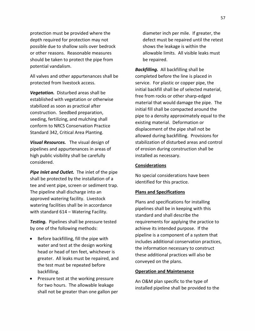
57
protection must be provided where the
depth required for protection may not
possible due to shallow soils over bedrock
or other reasons. Reasonable measures
should be taken to protect the pipe from
potential vandalism.
All valves and other appurtenances shall be
protected from livestock access.
Vegetation. Disturbed areas shall be
established with vegetation or otherwise
stabilized as soon as practical after
construction. Seedbed preparation,
seeding, fertilizing, and mulching shall
conform to NRCS Conservation Practice
Standard 342, Critical Area Planting.
Visual Resources. The visual design of
pipelines and appurtenances in areas of
high public visibility shall be carefully
considered.
Pipe Inlet and Outlet. The inlet of the pipe
shall be protected by the installation of a
tee and vent pipe, screen or sediment trap.
The pipeline shall discharge into an
approved watering facility. Livestock
watering facilities shall be in accordance
with standard 614 – Watering Facility.
Testing. Pipelines shall be pressure tested
by one of the following methods:
Before backfilling, fill the pipe with
water and test at the design working
head or head of ten feet, whichever is
greater. All leaks must be repaired, and
the test must be repeated before
backfilling.
Pressure test at the working pressure
for two hours. The allowable leakage
shall not be greater than one gallon per
diameter inch per mile. If greater, the
defect must be repaired until the retest
shows the leakage is within the
allowable limits. All visible leaks must
be repaired.
Backfilling. All backfilling shall be
completed before the line is placed in
service. For plastic or copper pipe, the
initial backfill shall be of selected material,
free from rocks or other sharp-edged
material that would damage the pipe. The
initial fill shall be compacted around the
pipe to a density approximately equal to the
existing material. Deformation or
displacement of the pipe shall not be
allowed during backfilling. Provisions for
stabilization of disturbed areas and control
of erosion during construction shall be
installed as necessary.
Considerations
No special considerations have been
identified for this practice.
Plans and Specifications
Plans and specifications for installing
pipelines shall be in keeping with this
standard and shall describe the
requirements for applying the practice to
achieve its intended purpose. If the
pipeline is a component of a system that
includes additional conservation practices,
the information necessary to construct
these additional practices will also be
conveyed on the plans.
Operation and Maintenance
An O&M plan specific to the type of
installed pipeline shall be provided to the

58
landowner. The plan shall include, but not
be limited to, the following provisions:
Opening/closing valves to prevent
excessive water hammer;
Filling at the specified rate
requirements;
Inspecting and testing valves, pressure
regulators, pumps, switches and other
appurtenances;
Maintaining erosion protection at
outlets;
Checking for debris, minerals, algae and
other materials which may restrict
system flow; and
Draining and/or providing for cold
weather operation of the system.
WATER WELL
Definition
A well-constructed or improved to provide
water for irrigation, livestock, wildlife, or
recreation.
Purpose
To facilitate proper use of vegetation on
rangeland, pastures, and wildlife areas; to
supply the water requirements of livestock
and wildlife; to provide an adequate supply
of water for conservation irrigation; and to
provide for human use at recreation sites.
Condition Where Practice Applies
All irrigation wells shall be planned and
located to serve as a source of water for an
irrigation water distribution or conveyance
system designed to facilitate the
conservation use of the soil and water
resources on a farm or group of farms.
Irrigation wells are limited to geological
sites where sufficiently large volumes of
underground water are available at a rate
that will permit practical irrigation of the
land on which the water is to be used. Wells
may be the only source of water or they
may supplement other sources. The land on
which the water is to be used must be
suitable for the production of locally
adapted crops grown under irrigation
farming. The water must be of adequate
quality to insure that it will not materially
reduce the productive capacity of the soil
on which it is to be used. Wells are
applicable on rangeland, pastures,
cropland, and wildlife, and recreation areas
where present water facilities are
inadequate and the underground water
supply is adequate in quantity and quality
for the purpose to be served and can be
developed at an economical cost.
Design Criteria
General. The suitability of the well site and
the type of well installed shall be based on
detailed geologic investigations, including
test well drilling, on ground water
assessment studied made by local, state, or
federal agencies, or on reliable local
experience. The design should include
ground water conservation measures,
provisions for controlling contamination
from one aquifer to another in the well, and
method for obtaining a maximum supply of
sediment-free water.
Well diameter. The diameter of the well
shall be adequate to meet the yield capacity
of the information in the relation to the
nature and extent of the water-bearing area
and to permit the installation of a pump to

59
deliver the needed amount of water to the
projected lift elevation.
Casing and materials. Wells shall be cased,
but the lower sections passing through
consolidated strata do not require casing.
Material shall meet the requirements
detailed under "Well Specifications."
The maximum depth for well casings shall
be based on critical collapse pressure as
calculated by the Cleindeinst Equation in
ASTM-F-480, appendix X2. Depth, as used in
this standard, applies to the difference in
static head between the inside and outside
of the casing. This can be determined by
measuring the static head or by using the
total depth of the well.
Table 1. — Maximum depth of installation
forplastic (SDR-PR) pipe
Table 2 gives the dimension and maximum
depth of installation for PVC Schedules 40
and 80 pipe constructed of material having
a modules of elasticity equal to 400,000
lb/in.2. The factors give at the bottom of
this table may be used in calculating depth
limitations for ABS Schedules 40 and 80
pipe and other PVC classifications.
Figure 1 can be used in determining the
maximum depth of plastic and fiberglass
casings not covered by tables 1 and 2.
Table 3 gives the dimensions and maximum
depth of installation for reinforced plastic
mortar (RPM) well casings of various sizes
and wall thickness.
Asbestos-cement and concrete water well
casings shall be limited to wells not greater
than 500 ft. in depth.
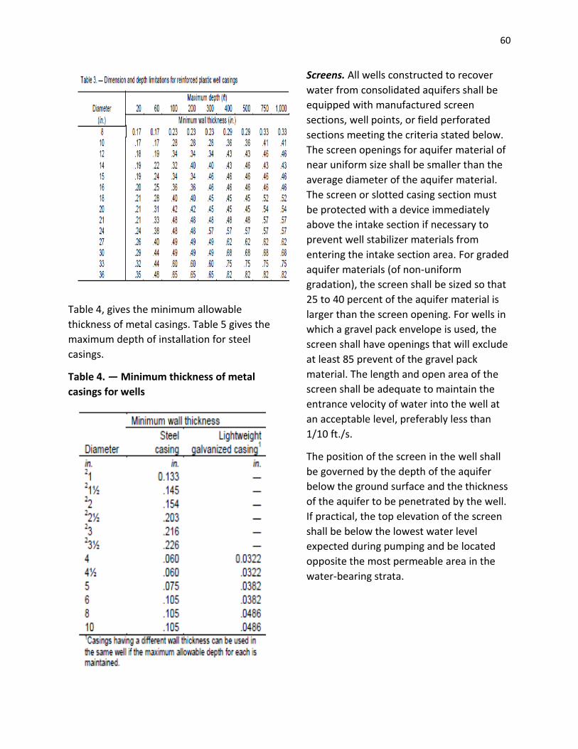
60
Table 4, gives the minimum allowable
thickness of metal casings. Table 5 gives the
maximum depth of installation for steel
casings.
Table 4. — Minimum thickness of metal
casings for wells
Screens. All wells constructed to recover
water from consolidated aquifers shall be
equipped with manufactured screen
sections, well points, or field perforated
sections meeting the criteria stated below.
The screen openings for aquifer material of
near uniform size shall be smaller than the
average diameter of the aquifer material.
The screen or slotted casing section must
be protected with a device immediately
above the intake section if necessary to
prevent well stabilizer materials from
entering the intake section area. For graded
aquifer materials (of non-uniform
gradation), the screen shall be sized so that
25 to 40 percent of the aquifer material is
larger than the screen opening. For wells in
which a gravel pack envelope is used, the
screen shall have openings that will exclude
at least 85 prevent of the gravel pack
material. The length and open area of the
screen shall be adequate to maintain the
entrance velocity of water into the well at
an acceptable level, preferably less than
1/10 ft./s.
The position of the screen in the well shall
be governed by the depth of the aquifer
below the ground surface and the thickness
of the aquifer to be penetrated by the well.
If practical, the top elevation of the screen
shall be below the lowest water level
expected during pumping and be located
opposite the most permeable area in the
water-bearing strata.
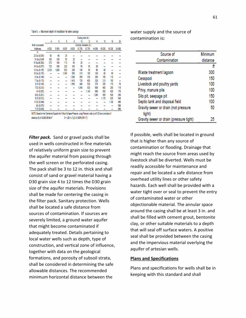
61
Filter pack. Sand or gravel packs shall be
used in wells constructed in fine materials
of relatively uniform grain size to prevent
the aquifer material from passing through
the well screen or the perforated casing.
The pack shall be 3 to 12 in. thick and shall
consist of sand or gravel material having a
D30 grain size 4 to 12 times the D30 grain
size of the aquifer materials. Provisions
shall be made for centering the casing in
the filter pack. Sanitary protection. Wells
shall be located a safe distance from
sources of contamination. If sources are
severely limited, a ground water aquifer
that might become contaminated if
adequately treated. Details pertaining to
local water wells such as depth, type of
construction, and vertical zone of influence,
together with data on the geological
formations, and porosity of subsoil strata,
shall be considered in determining the safe
allowable distances. The recommended
minimum horizontal distance between the
water supply and the source of
contamination is:
If possible, wells shall be located in ground
that is higher than any source of
contamination or flooding. Drainage that
might reach the source from areas used by
livestock shall be diverted. Wells must be
readily accessible for maintenance and
repair and be located a safe distance from
overhead utility lines or other safety
hazards. Each well shall be provided with a
water tight over or seal to prevent the entry
of contaminated water or other
objectionable material. The annular space
around the casing shall be at least 3 in. and
shall be filled with cement grout, bentonite
clay, or other suitable materials to a depth
that will seal off surface waters. A positive
seal shall be provided between the casing
and the impervious material overlying the
aquifer of artesian wells.
Plans and Specifications
Plans and specifications for wells shall be in
keeping with this standard and shall
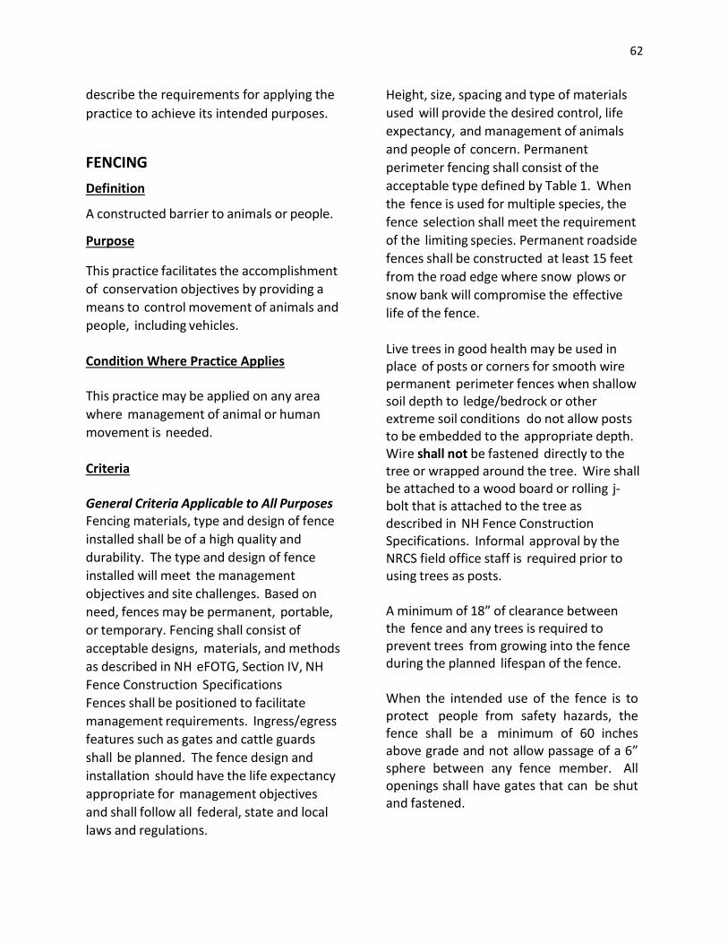
62
describe the requirements for applying the
practice to achieve its intended purposes.
FENCING
Definition A constructed barrier to animals or people. Purpose This practice facilitates the accomplishment
of conservation objectives by providing a
means to control movement of animals and
people, including vehicles.
Condition Where Practice Applies This practice may be applied on any area
where management of animal or human
movement is needed.
Criteria General Criteria Applicable to All Purposes Fencing materials, type and design of fence
installed shall be of a high quality and
durability. The type and design of fence
installed will meet the management
objectives and site challenges. Based on
need, fences may be permanent, portable,
or temporary. Fencing shall consist of
acceptable designs, materials, and methods
as described in NH eFOTG, Section IV, NH
Fence Construction Specifications
Fences shall be positioned to facilitate
management requirements. Ingress/egress
features such as gates and cattle guards
shall be planned. The fence design and
installation should have the life expectancy
appropriate for management objectives
and shall follow all federal, state and local
laws and regulations.
Height, size, spacing and type of materials
used will provide the desired control, life
expectancy, and management of animals
and people of concern. Permanent
perimeter fencing shall consist of the
acceptable type defined by Table 1. When
the fence is used for multiple species, the
fence selection shall meet the requirement
of the limiting species. Permanent roadside
fences shall be constructed at least 15 feet
from the road edge where snow plows or
snow bank will compromise the effective
life of the fence.
Live trees in good health may be used in place of posts or corners for smooth wire permanent perimeter fences when shallow soil depth to ledge/bedrock or other extreme soil conditions do not allow posts to be embedded to the appropriate depth. Wire shall not be fastened directly to the tree or wrapped around the tree. Wire shall be attached to a wood board or rolling j-bolt that is attached to the tree as described in NH Fence Construction Specifications. Informal approval by the NRCS field office staff is required prior to using trees as posts. A m inim um of 18” of clearance between the fence and any trees is required to prevent trees from growing into the fence during the planned lifespan of the fence. When the intended use of the fence is to protect people from safety hazards, the fence shall be a minimum of 60 inches above grade and not allo w p assage of a 6” sphere between any fence member. All openings shall have gates that can be shut and fastened.
63
Considerations The fence design and location should consider: topography, soil properties, livestock management and safety, livestock trailing, wildlife class and movement, location and adequacy of water facilities, development of potential grazing systems, human access and safety, landscape aesthetics, erosion problems, moisture conditions, flooding potential, stream crossings, and durability of materials. When appropriate, natural barriers should be utilized instead of fencing. Where applicable, cleared rights-of-way may be established which would facilitate fence construction and maintenance. Avoid clearing of vegetation during the nesting season for migratory birds. Fences across gullies, canyons or streams may require special bracing, designs or approaches. Fence design and location should consider ease of access for construction, repair and maintenance. Fence construction requiring the removal of existing unusable fence should provide for the proper disposal of scrap materials to prevent harm to animals, people and equipment. Wire should normally be attached on the side of the post receiving the most animal pressure. Treatment of wood posts with certain preservatives may not be allowed in certified organic systems. Producers should check with their certifying agency regarding requirements. Plans and Specifications Plans and specifications are to be prepared for all fence types, installations and specific sites. Requirements for applying the
practice to achieve all of its intended purposes shall be described. The completed work is to be checked and documented using the NH-382 job sheet to verify that the practice is complete according to NRCS standards and specifications. NRCS field staff shall contact the state agronomist for inquiries relating to fencing for grazing systems and livestock exclusion, and the engineering staff for inquiries relating to safety fencing. Operation and Maintenance Regular inspection of fences should be part of an ongoing maintenance program. Inspection of fences after storms and other disturbance events is necessary to insure the continued proper function of the fence. Maintenance and repairs will be performed in a timely manner as needed, including tree/limb removal and water gap replacement. Electric fences shall be checked regularly to determine the voltage of the fence. If voltage is not sufficient, determine the cause and correct it. Any vegetation in contact with the fence can cause decreased voltage. Vegetative growth beneath and around the electric fence should be controlled mechanically by grazing or mowing, or as a last resort, with chemicals. Remove and properly discard all broken fencing material and hardware. All necessary precautions should be taken to ensure the safety of construction and maintenance crews. Wire that is overstretched may break and recoil. Eye and hand protection should be worn.

64
REFERENCES Bell, H. Bell, H.M. 1973. Rangeland management for livestock production. University of Oklahoma Press. Heady, H.F. and R.D. Child. 1994. Rangeland ecology and management. Western Press. Holechek, J.L., R.D. Pieper, and C.H. Herbel. 2001. Range management: principles and practices. Prentice Hall. Stoddard, L.A., A.D. Smith, and T.W. Box. 1975. Range management. McGraw-Hill Book Company. United States Department of Interior, Bureau of Land Management and United States Department of Agriculture, Forest Service. 1988. Fences. Missoula Technology and Development Center. United States Department of Agriculture, Natural Resources Conservation Service. 2005. Electric fencing for serious graziers. Columbia, Mo. United States Department of Agriculture, Natural Resources Conservation Service. 2003. National range and pasture handbook, revision 1. Washington, DC. Vallentine, J.F. 1971. Range development and improvement. Brigham Young University Press Table 1 Permanent Perimeter Fence Selection Criteria Fence design and construction must meet the minimum requirements for controlling specific animal types.
Abbreviations and specifications for use
HT = High tensile

65
HTS = 12.5 gauge high tensile smooth steel
wire with class 3 galvanization or zinc-
aluminum or better
HTA = 12.5 gauge high tensile smooth
aluminum alloy wire
Top wire = (i) 2 twisted strands of 15.5
gauge high tensile wire with class 3
galvanizing (or better) with 4 point barbs on
5 inch centers, or (ii) electrified HTS/HTA
placed at least 4 inches above woven wire.
Barbed wire shall never be electrified or
used with an electrified fence. Barbed wire
or bare HTS wire shall not be used for
horses.
Based on the type of livestock, use the
information in this table as the minimum
criteria for fence purpose. More strands of
wire and a different spacing may be
required depending on the fence
manufacturer’s recommendations and
landowner objectives.
With woven wire and board fences consider
using one or more wires offset on the inside
to prevent livestock from rubbing or leaning
on fence. Offset wire should be electrified
HTS, HTA, or polyrope/polywire. Offset
wires should be a minimum of 6” away from
the fence posts.
CHAPTER V
STABILIZATION AND EROSION CONTROL
Intent
The intent when using these practices is to avoid wetlands if possible and if not to minimize
impacts to the wetlands by protecting characteristics, functions and values. Typically the
wetlands affected by these practices are classified as Wet Meadow, and occur in an agricultural
field and have hydric soils that are defined as soils that, in an undrained condition, are
saturated, flooded, or ponded long enough during a growing season to develop an anaerobic
condition that supports the growth and regeneration of hydrophytic vegetation. Additional
jurisdictional wetland areas may include forested wetlands, intermittent stream, farm ponds
or other areas that support and are necessary to an existing agricultural operation.
FILTER STRIP
Definition
A strip or area of herbaceous vegetation
situated between cropland, grazing land, or
disturbed land (including forestland) and
environmentally sensitive areas.
Purpose
To reduce sediment, particulate organics, and sediment adsorbed contaminant loading in runoff
To reduce dissolved contaminant loading in runoff
To serve as Zone 3 of a Riparian Forest Buffer, Practice Standard 391

66
To reduce sediment, particulate organics, and sediment adsorbed contaminant loading in surface irrigation tailwater.
To restore, create or enhance herbaceous habitat for wildlife and beneficial insects.
To maintain or enhance watershed functions and values
Condition Where Practice Applies
This practice applies:
In areas situated below cropland,
grazing land, or disturbed land
(including forest land)
Where sediment, particulate organic
matter and/or dissolved contaminants
may leave these areas and are entering
environmentally sensitive areas
In areas where permanent vegetative
establishment is needed to enhance
wildlife and beneficial insects, or
maintain or enhance watershed
function.
This practice applies when planned as part
of a conservation management system.
Criteria
General criteria applicable to all purposes
Filter strips shall be designated as vegetated
areas to treat runoff and are not part of the
adjacent cropland rotation.
Overland flow entering the filter strip shall
be primarily sheet flow. Concentrated flow
shall be dispersed.
State listed noxious weeds will not be
established in the filter strip and will be
controlled if present.
Filter strip establishment shall comply with
local, state and federal regulations.
Additional criteria to reduce sediment,
particulate organics, and sediment-
adsorbed contaminant loading in runoff
Filter strip flow length shall be determined
based on field slope percent and length,
and filter strip slope percent, erosion rate,
amount and particle size distribution of
sediment delivered to the filter strip,
density and height of the filter strip
vegetation, and runoff volume associated
with erosion producing events. The
minimum flow length for this purpose shall
be 20 feet.
Filter strip location requirements:
The filter strip shall be located along the
downslope edge of a field or disturbed
area. To the extent practical it shall be
placed on the approximate contour.
Variation in placement on the contour
should not exceed a 0.5% longitudinal
(perpendicular to the flow length)
gradient.
The drainage area above the filter strip
shall have greater than 1% but less than
10% slopes.
The ratio of the drainage area to the
filter strip area shall be less than 70:1 in
regions with RUSLE-R factor values 0-35,
60:1 in regions with RUSLE-R factor
values 35-175, and 50:1 in regions with
RUSLE-R factor values of more than 175.
The average annual sheet and rill
erosion rate above the filter strip shall
be less than 10 tons per acre per year.
The filter strip shall be established to
permanent herbaceous vegetation
67
consisting of a single species or a mixture of
grasses, legumes and/or other forbs
adapted to the soil, climate, and nutrients,
chemicals, and practices used in the current
management system. Species selected shall
have stiff stems and a high stem density
near the ground surface. Stem density shall
be such that the stem spacing does not
exceed 1 inch.
Additional criteria to reduce dissolved
contaminants in runoff
The criteria given in “Additional criteria to
reduce sediment, particulate organics, and
sediment adsorbed contaminant loading in
runoff” also apply to this purpose.
Filter strip flow length required to reduce
dissolved contaminants in runoff shall be
based on management objectives,
contaminants of concern, and the volume
of runoff from the filter strip’s drainage
area compared with the filter strip’s area
and infiltration capacity.
The flow length determined for this
purpose shall be in addition to the flow
length determined for reducing sediment,
particulate organics, and sediment-
adsorbed contaminant loading in runoff.
The minimum flow length for this purpose
shall be 30 feet.
Additional criteria to serve as Zone 3 of a
Riparian Forest Buffer, Practice Standard
391
Except for the location requirements, the
criteria given in “Additional criteria to
reduce sediment, particulate organics, and
sediment adsorbed contaminant loading in
runoff” also apply to this purpose.
If concentrated flows entering Zone 3 are
greater than the filter strip’s ability to
disperse them, other means of dispersal,
such as spreading devices, must be
incorporated.
Additional criteria to reduce sediment,
particulate organics, and sediment
adsorbed contaminant loading in surface
irrigation tailwater
Filter strip vegetation may be a small grain
or other suitable annual with a plant
spacing that does not exceed 4 inches.
Filter strips shall be established early
enough prior to the irrigation season so that
the vegetation can withstand sediment
deposition from the first irrigation.
The flow length shall be based on
management objectives.
Additional criteria to restore, create, or
enhance herbaceous habitat for wildlife
and beneficial insects
If this purpose is intended in combination
with one or more of the previous purposes,
then the minimum criteria for the previous
purpose(s) must be met. Additional filter
strip flow length devoted to this purpose
must be added to the length required for
the other purpose(s).
Any addition to the flow length for wildlife
or beneficial insects shall be added to the
downhill slope of the filter strip. Vegetation
to enhance wildlife may be added to that
portion of the filter strip devoted to other
purposes to the extent they do not detract
from its primary functions.
Plant species selected for this purpose shall
be for permanent vegetation adapted to

68
the wildlife or beneficial insect
population(s) targeted.
If this is the only purpose, filter strip width
and length shall be based on requirements
of the targeted wildlife or insects. Density
of the vegetative stand established for this
purpose shall consider targeted wildlife
habitat requirements and encourage plant
diversity. Dispersed woody vegetation may
be used to the extent it does not interfere
with herbaceous vegetative growth, or
operation and maintenance of the filter
strip.
The filter strip shall not be mowed during
the nesting season of the target wildlife.
Livestock and vehicular traffic in the filter
strip shall be excluded during the nesting
season of the target species.
Additional criteria to maintain or enhance
watershed functions and values
Filter strips shall be strategically located to
enhance connectivity of corridors and non-
cultivated patches of vegetation within the
watershed.
Filter strips should be strategically located
to enhance aesthetics of the watershed.
Plant species selected for this purpose shall
be for establishment of permanent
vegetation.
Considerations
Filter strips should be strategically located
to reduce runoff, and increase infiltration
and ground water recharge throughout the
watershed.
Filter strips for the single purposes of
wildlife/beneficial insect habitat or to
enhance watershed function should be
strategically located to intercept
contaminants thereby enhancing the water
quality of the watershed.
To avoid damage to the filter strip consider
using vegetation that is somewhat tolerant
to herbicides used in the upslope crop
rotation.
Consider using this practice to enhance the
conservation of declining species of wildlife,
including those that are threatened or
endangered.
Consider using this practice to protect
National Register listed or eligible
(significant) archaeological and traditional
cultural properties from potential damaging
contaminants.
Filter strip size should be adjusted to a
greater flow length to accommodate
harvest and maintenance equipment.
Plans and Specifications
Based on this standard, plans and
specifications shall be prepared for each
specific field site where a filter strip will be
installed. A plan includes information about
the location, construction sequence,
vegetation establishment, and management
and maintenance requirements.
Specifications will include:
Length, width, and slope of the filter
strip to accomplish the planned purpose
(length refers to flow length across the
filter strip).
Species selection and seeding or
sprigging rates to accomplish the
planned purpose

69
Planting dates, care, and handling of the
seed to ensure that planted materials
have an acceptable rate of survival
A statement that only viable, high
quality, and regionally adapted seed will
be used
Site preparation sufficient to establish
and grow selected species
Operation and Maintenance
For the purposes of filtering contaminants,
permanent filter strip vegetative plantings
should be harvested as appropriate to
encourage dense growth, maintain an
upright growth habit, and remove nutrients
and other contaminants that are contained
in the plant tissue.
Control undesired weed species, especially
state-listed noxious weeds.
Prescribed burning may be used to manage
and maintain the filter strip when an
approved burn plan has been developed.
Inspect the filter strip after storm events
and repair any gullies that have formed,
remove unevenly deposited sediment
accumulation that will disrupt sheet flow,
re-seed disturbed areas, and take other
measures to prevent concentrated flow
through the filter strip
Apply supplemental nutrients as needed to
maintain the desired species composition
and stand density of the filter strip.
To maintain or restore the filter strip’s
function, periodically re-grade the filter
strip area when sediment deposition at the
filter strip-field interface jeopardizes its
function, and then reestablish the filter strip
vegetation, if needed. If wildlife habitat is a
purpose, destruction of vegetation within
the portion of the strip devoted to that
purpose should be minimized by re- grading
only to the extent needed to remove
sediment and fill concentrated flow areas.
Grazing shall not be permitted in the filter
strip unless a controlled grazing system is
being implemented. Grazing will be
permitted under a controlled grazing
system only when soil moisture conditions
support livestock traffic without excessive
compaction.
GRADE STABILIZATION STRUCTURE
Definition
A structure used to control the grade and
head cutting in natural or artificial channels.
Conditions Where Practice Applies
In areas where the concentration and flow
velocity of water require structures to
stabilize the grade in channels or to control
gully erosion. Special attention shall be
given to maintaining or improving habitat
for fish and wildlife where applicable.
Criteria
The structure must be designed for stability
after installation. The crest of the inlet
must be set at an elevation that stabilize
upstream head cutting.
Dams are regulated by the New Hampshire
Dam Bureau and may require a permit.
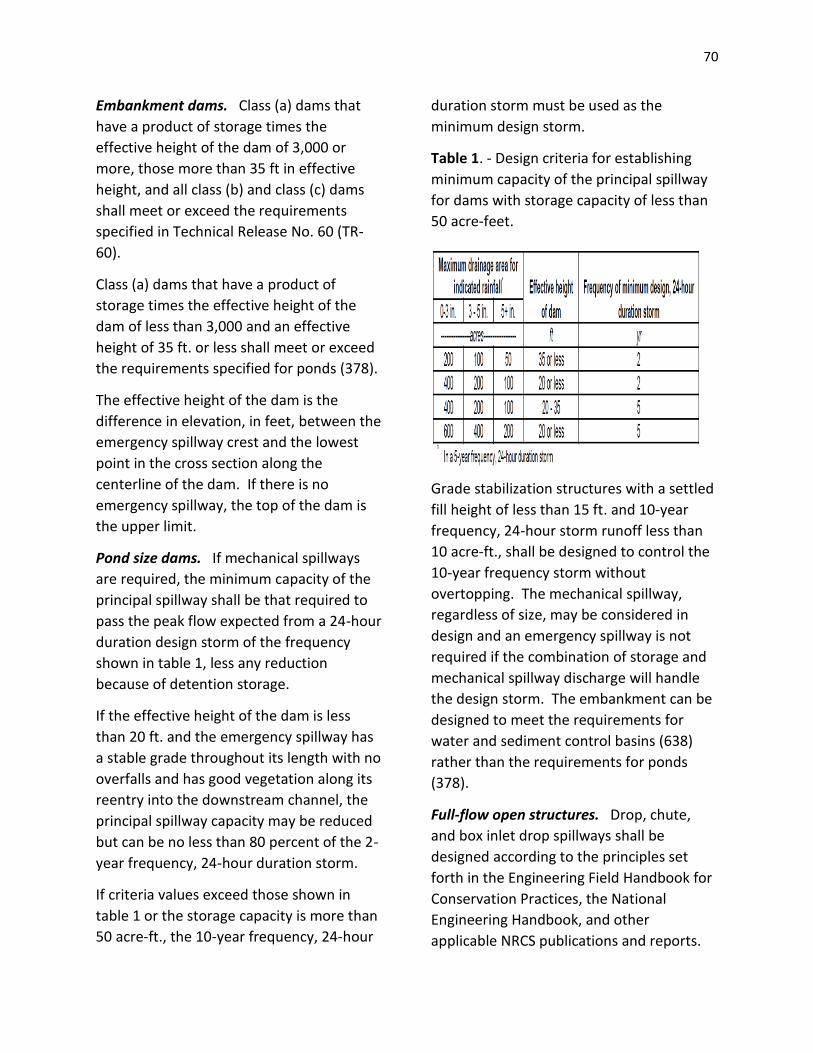
70
Embankment dams. Class (a) dams that
have a product of storage times the
effective height of the dam of 3,000 or
more, those more than 35 ft in effective
height, and all class (b) and class (c) dams
shall meet or exceed the requirements
specified in Technical Release No. 60 (TR-
60).
Class (a) dams that have a product of
storage times the effective height of the
dam of less than 3,000 and an effective
height of 35 ft. or less shall meet or exceed
the requirements specified for ponds (378).
The effective height of the dam is the
difference in elevation, in feet, between the
emergency spillway crest and the lowest
point in the cross section along the
centerline of the dam. If there is no
emergency spillway, the top of the dam is
the upper limit.
Pond size dams. If mechanical spillways
are required, the minimum capacity of the
principal spillway shall be that required to
pass the peak flow expected from a 24-hour
duration design storm of the frequency
shown in table 1, less any reduction
because of detention storage.
If the effective height of the dam is less
than 20 ft. and the emergency spillway has
a stable grade throughout its length with no
overfalls and has good vegetation along its
reentry into the downstream channel, the
principal spillway capacity may be reduced
but can be no less than 80 percent of the 2-
year frequency, 24-hour duration storm.
If criteria values exceed those shown in
table 1 or the storage capacity is more than
50 acre-ft., the 10-year frequency, 24-hour
duration storm must be used as the
minimum design storm.
Table 1. - Design criteria for establishing
minimum capacity of the principal spillway
for dams with storage capacity of less than
50 acre-feet.
Grade stabilization structures with a settled
fill height of less than 15 ft. and 10-year
frequency, 24-hour storm runoff less than
10 acre-ft., shall be designed to control the
10-year frequency storm without
overtopping. The mechanical spillway,
regardless of size, may be considered in
design and an emergency spillway is not
required if the combination of storage and
mechanical spillway discharge will handle
the design storm. The embankment can be
designed to meet the requirements for
water and sediment control basins (638)
rather than the requirements for ponds
(378).
Full-flow open structures. Drop, chute,
and box inlet drop spillways shall be
designed according to the principles set
forth in the Engineering Field Handbook for
Conservation Practices, the National
Engineering Handbook, and other
applicable NRCS publications and reports.
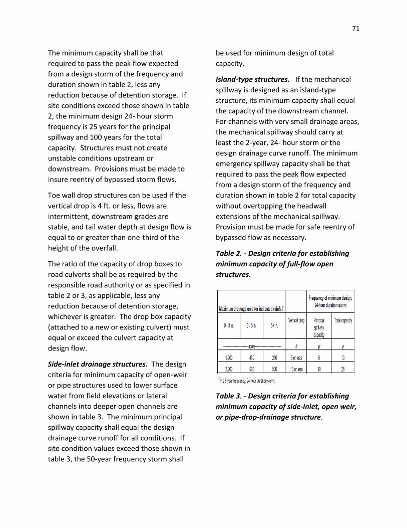
71
The minimum capacity shall be that
required to pass the peak flow expected
from a design storm of the frequency and
duration shown in table 2, less any
reduction because of detention storage. If
site conditions exceed those shown in table
2, the minimum design 24- hour storm
frequency is 25 years for the principal
spillway and 100 years for the total
capacity. Structures must not create
unstable conditions upstream or
downstream. Provisions must be made to
insure reentry of bypassed storm flows.
Toe wall drop structures can be used if the
vertical drop is 4 ft. or less, flows are
intermittent, downstream grades are
stable, and tail water depth at design flow is
equal to or greater than one-third of the
height of the overfall.
The ratio of the capacity of drop boxes to
road culverts shall be as required by the
responsible road authority or as specified in
table 2 or 3, as applicable, less any
reduction because of detention storage,
whichever is greater. The drop box capacity
(attached to a new or existing culvert) must
equal or exceed the culvert capacity at
design flow.
Side-inlet drainage structures. The design
criteria for minimum capacity of open-weir
or pipe structures used to lower surface
water from field elevations or lateral
channels into deeper open channels are
shown in table 3. The minimum principal
spillway capacity shall equal the design
drainage curve runoff for all conditions. If
site condition values exceed those shown in
table 3, the 50-year frequency storm shall
be used for minimum design of total
capacity.
Island-type structures. If the mechanical
spillway is designed as an island-type
structure, its minimum capacity shall equal
the capacity of the downstream channel.
For channels with very small drainage areas,
the mechanical spillway should carry at
least the 2-year, 24- hour storm or the
design drainage curve runoff. The minimum
emergency spillway capacity shall be that
required to pass the peak flow expected
from a design storm of the frequency and
duration shown in table 2 for total capacity
without overtopping the headwall
extensions of the mechanical spillway.
Provision must be made for safe reentry of
bypassed flow as necessary.
Table 2. - Design criteria for establishing
minimum capacity of full-flow open
structures.
Table 3. - Design criteria for establishing
minimum capacity of side-inlet, open weir,
or pipe-drop-drainage structure.

72
Landscape resources. In highly visible
public areas and those associated with
recreation, careful considerations should be
given to landscape resources. Landforms,
structural materials, water elements, and
plant materials should visually and
functionally complement their
surroundings. Excavated material and cut
slopes should be shaped to blend with the
natural topography. Shorelines can be
shaped and islands created to add visual
interest and valuable wildlife habitat.
Exposed concrete surfaces may be formed
to add texture or finished to reduce
reflection and to alter color contrast. Site
selection can be used to reduce adverse
impacts or create desirable focal points.
General
Earth embankment and emergency
spillways of structures for which criteria are
not provided under the standard for ponds
(378) or in TR-60 must be stable for all
anticipated conditions. If earth spillways
are used, they must be designed to handle
the total capacity flow indicated in Tables 2
or 3 without overtopping the dam. The
foundation preparation, compaction, top
width, and side slopes must ensure a stable
dam for anticipated flow conditions.
Discharge from the structure shall be
sufficient that no crop damage results from
flow detention.
Necessary sediment storage capacity must
equal the expected life of the structure,
unless a provision is made for periodic
cleanout.
The earth embankment pond structures are
potentially hazardous and precautions must
be taken to prevent serious injury or loss of
life.
Protective guardrails, warning signs, fences,
or lifesaving equipment shall be added as
needed.
If the area is used for livestock, the
structures, earthfill, vegetated spillways,
and other areas should be fenced as
necessary to protect the structure. Near
urban areas, fencing may be necessary to
control access and exclude traffic that may
damage the structure or to prevent serious
injury or death to trespassers.
Protection. The exposed surfaces of the
embankment, earth spillway, borrow area,
and other areas disturbed during
construction shall be seeded or sodded as
necessary to prevent erosion. If climatic
conditions preclude the use of vegetation,
non-vegetative coverings such as gravel or
other mulches may be used.
Considerations
Water Quantity
Effects on volumes and rates of runoff,
evaporation, deep percolation and
ground water recharge.
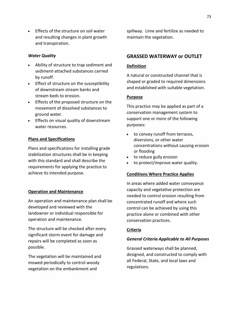
73
Effects of the structure on soil water
and resulting changes in plant growth
and transpiration.
Water Quality
Ability of structure to trap sediment and
sediment-attached substances carried
by runoff.
Effect of structure on the susceptibility
of downstream stream banks and
stream beds to erosion.
Effects of the proposed structure on the
movement of dissolved substances to
ground water.
Effects on visual quality of downstream
water resources.
Plans and Specifications
Plans and specifications for installing grade
stabilization structures shall be in keeping
with this standard and shall describe the
requirements for applying the practice to
achieve its intended purpose.
Operation and Maintenance
An operation and maintenance plan shall be
developed and reviewed with the
landowner or individual responsible for
operation and maintenance.
The structure will be checked after every
significant storm event for damage and
repairs will be completed as soon as
possible.
The vegetation will be maintained and
mowed periodically to control woody
vegetation on the embankment and
spillway. Lime and fertilize as needed to
maintain the vegetation.
GRASSED WATERWAY or OUTLET
Definition
A natural or constructed channel that is
shaped or graded to required dimensions
and established with suitable vegetation.
Purpose
This practice may be applied as part of a
conservation management system to
support one or more of the following
purposes:
to convey runoff from terraces, diversions, or other water concentrations without causing erosion or flooding
to reduce gully erosion to protect/improve water quality.
Conditions Where Practice Applies
In areas where added water conveyance
capacity and vegetative protection are
needed to control erosion resulting from
concentrated runoff and where such
control can be achieved by using this
practice alone or combined with other
conservation practices.
Criteria
General Criteria Applicable to All Purposes
Grassed waterways shall be planned,
designed, and constructed to comply with
all Federal, State, and local laws and
regulations.
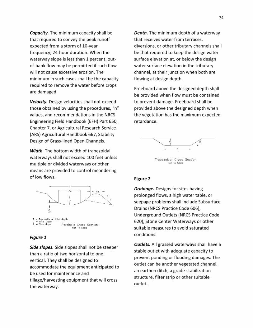
74
Capacity. The minimum capacity shall be
that required to convey the peak runoff
expected from a storm of 10-year
frequency, 24-hour duration. When the
waterway slope is less than 1 percent, out-
of-bank flow may be permitted if such flow
will not cause excessive erosion. The
minimum in such cases shall be the capacity
required to remove the water before crops
are damaged.
Velocity. Design velocities shall not exceed
those obtained by using the procedures, “n”
values, and recommendations in the NRCS
Engineering Field Handbook (EFH) Part 650,
Chapter 7, or Agricultural Research Service
(ARS) Agricultural Handbook 667, Stability
Design of Grass-lined Open Channels.
Width. The bottom width of trapezoidal
waterways shall not exceed 100 feet unless
multiple or divided waterways or other
means are provided to control meandering
of low flows.
Figure 1
Side slopes. Side slopes shall not be steeper
than a ratio of two horizontal to one
vertical. They shall be designed to
accommodate the equipment anticipated to
be used for maintenance and
tillage/harvesting equipment that will cross
the waterway.
Depth. The minimum depth of a waterway
that receives water from terraces,
diversions, or other tributary channels shall
be that required to keep the design water
surface elevation at, or below the design
water surface elevation in the tributary
channel, at their junction when both are
flowing at design depth.
Freeboard above the designed depth shall
be provided when flow must be contained
to prevent damage. Freeboard shall be
provided above the designed depth when
the vegetation has the maximum expected
retardance.
Figure 2
Drainage. Designs for sites having
prolonged flows, a high water table, or
seepage problems shall include Subsurface
Drains (NRCS Practice Code 606),
Underground Outlets (NRCS Practice Code
620), Stone Center Waterways or other
suitable measures to avoid saturated
conditions.
Outlets. All grassed waterways shall have a
stable outlet with adequate capacity to
prevent ponding or flooding damages. The
outlet can be another vegetated channel,
an earthen ditch, a grade-stabilization
structure, filter strip or other suitable
outlet.

75
Vegetative Establishment. Grassed
waterways shall be vegetated according to
NRCS Conservation Practice Standard
Critical Area Planting, Code 342.
When cuts are expected to exceed 6 inches,
topsoil shall be saved to spread on the
newly constructed waterway to facilitate
the establishment of vegetative cover. W
here this is done, the waterway shall be
over excavated to allow for placement of
topsoil without encroaching on the design
cross section.
Seedbed preparation, time of seeding,
mixture rate, stabilizing crop, mulching, or
mechanical means of stabilizing, fertilizer,
and lime requirements shall be specified for
each applicable area.
Establish vegetation as soon as conditions
permit. Use mulch anchoring, nurse crop,
rock, straw or hay bale dikes, filter fences,
or runoff diversion to protect the
vegetation until it is established. In
waterways with design flow velocities
greater than 3.0 feet per second, the flow
of water shall be diverted around or away
from the waterway until the vegetation is
established.
Considerations
Important wildlife habitat, such as woody
cover or wetlands, should be avoided or
protected if possible when siting the
grassed waterway. If trees and shrubs are
incorporated, they should be retained or
planted in the periphery of grassed
waterways so they do not interfere with
hydraulic functions. Mid- or tall bunch
grasses and perennial forbs may also be
planted along waterway margins to improve
wildlife habitat. Waterways with these
wildlife features are more beneficial when
connecting other habitat types; e.g.,
riparian areas, wooded tracts and wetlands.
Water-tolerant vegetation may be an
alternative on some wet sites if the
vegetation can be harvested during dry
periods.
Use irrigation in dry regions or
supplemental irrigation as necessary to
promote germination and vegetation
establishment.
Provide livestock and vehicular crossings as
necessary to prevent damage to the
waterway and its vegetation.
Establish filter strips on each side of the
waterway to improve water quality where
dikes have not been used.
Add width of appropriate vegetation to the
sides of the waterway for wildlife habitat.
Plans and Specifications
Plans and specifications for grassed
waterways shall be in keeping with this
standard and shall describe the
requirements for applying the practice to
achieve its intended purpose(s).
Operation and Maintenance
An operation and maintenance plan shall be
provided to and reviewed with the
landowner. The plan shall include the
following items and others as appropriate.
A maintenance program shall be
established to maintain waterway capacity,
vegetative cover, and outlet stability.

76
Vegetation damaged by machinery,
herbicides, or erosion must be repaired
promptly.
The primary seeding shall be inspected for
at least two years after construction, after
spring runoff, and after heavy rainfall
events.
Reinforcement grass seeding and mulching
shall be completed when existing stands are
less than ten plants per square foot. Lime
and fertilizer shall also be applied with
reinforcement seeding. During the first two
springs following establishment, topdress
with a minimum of 300 lbs. Of 10-10-10
fertilizer.
Check pH and apply lime according to soil
test recommendations.
Seeding shall be protected from
concentrated flow and grazing until
vegetation is established.
Minimize damage to vegetation by
excluding livestock whenever possible,
especially during wet periods.
Inspect grassed waterways regularly,
especially following heavy rains. Damaged
areas will be filled, compacted, and seeded
immediately. Remove sediment deposits to
maintain capacity of grassed waterway.
Landowners should be advised to avoid
areas where forbs have been established
when applying herbicides. Avoid using
waterways as turn-rows during tillage and
cultivation operations. Prescribed burning
and mowing may be appropriate to
enhance wildlife values, but must be
conducted to avoid peak nesting seasons
and reduced winter cover.
Mow or periodically graze vegetation to
maintain capacity and reduce sediment
deposition. Mowing should be completed
after August 15th to allow nesting birds to
leave.
Control noxious weeds.
Do not use as a field road. Avoid crossing
with heavy equipment when wet.
LEVEL SPREADER
Definition
A level spreader is an outlet constructed at
zero percent grade across the slope that
allows concentrated runoff to be discharged
at non-erosive velocities onto natural or
man-made areas that have existing
vegetation capable of preventing erosion.
Purpose
A level spreader changes concentrated flow
into sheet flow and then outlets it onto
stable areas without causing erosion. An
example would be at the outlet of a
diversion or a waterway.
Conditions Where Practice Applies
The level spreader is used where it can be
constructed on undisturbed soils, where the
area directly below the spreader is
stabilized be existing vegetation, where the
water will not re concentrate immediately
below the spreader, and where there is at
least 100 feet of vegetated area between
the spreader and state surface waters.

77
Considerations
Placement of the level spreader must allow
the water flowing over the level section to
leave the structure as a uniform, thin film of
water. The structure should outflow onto
naturally vegetated areas whenever
possible. The creation of a uniform level lip
for the water to spread over ·is critical.
Design Criteria
Length. The design length for a level
spreader shall be no more than 0.5 cfs. per
foot of level section based on the peak rate
of flow from the contributing designed
erosion control or storm water
management practice. The minimum
length of the spreader shall be 5 feet and
the maximum length shall be 50 feet.
Width. The minimum 11idth of the
spreader shall be 6 feet as· shown in Figure
1.
Depth. The depth of the level spreader as
measured from the lip shall be at least 6
inches.
The depth of the spreader shall be uniform
(See Figure 1) across the entire length.
Grade. The level spreader lip shall be
constructed on a zero percent grade to
insure uniform spreading of runoff. The last
50 feet of the channel leading into the level
spreader shall be constructed at a grade not
exceeding 1%.
Vegetation. The spreader shall be stabilized
in accordance with the appropriate grass
mixture selected from those found in the
Best Management Practice for Seeding for
Long-Term Cover. The spreader should be
mulched if necessary for the establishment
of good quality vegetation.
Outlets. Final discharge will be over the
level lip protected with erosion stops and
jute or Excelsior matting onto an existing
stabilized area. The stabilized area shall
have a complete vegetative cover sufficient
established to be erosion resistant.
Maintenance
The level spreader should be checked
periodically and after every major storm to
determine if the lip ·has been damaged and
to determine that the design conditions
have not changed. Any detrimental
sediment accumulation should be removed.
If rilling has taken place on the lip, then the
damage should be repaired and re-
vegetated. The vegetation should be
mowed occasionally to control weeds and
the encroachment of woody vegetation.
Clippings should be removed· and disposed
of outside the spreader and away from the
outlet area. Fertilization should be done as
necessary to keep the vegetation healthy
and dense.
Construction Specifications
Construct the level spreader lip on a
zero percent grade to insure uniform
spreading of runoff.
Level spreader shall be constructed on
undisturbed soil and not on fill.
An erosion stop shall be placed
vertically a minimum of six inches deep
in a slit trench one foot back of the level
lip and parallel to the lip. The erosion
stop shall extend the entire length of
the level lip.
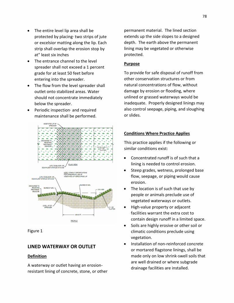
78
The entire level lip area shall be
protected by placing· two strips of jute
or excelsior matting along the lip. Each
strip shall overlap the erosion stop by
at" least six inches
The entrance channel to the level
spreader shall not exceed a 1 percent
grade for at least 50 feet before
entering into the spreader.
The flow from the level spreader shall
outlet onto stabilized areas. Water
should not concentrate immediately
below the spreader.
Periodic inspection· and required
maintenance shall be performed.
Figure 1
LINED WATERWAY OR OUTLET
Definition
A waterway or outlet having an erosion-
resistant lining of concrete, stone, or other
permanent material. The lined section
extends up the side slopes to a designed
depth. The earth above the permanent
lining may be vegetated or otherwise
protected.
Purpose
To provide for safe disposal of runoff from
other conservation structures or from
natural concentrations of flow, without
damage by erosion or flooding, where
unlined or grassed waterways would be
inadequate. Properly designed linings may
also control seepage, piping, and sloughing
or slides.
Conditions Where Practice Applies
This practice applies if the following or
similar conditions exist:
Concentrated runoff is of such that a
lining is needed to control erosion.
Steep grades, wetness, prolonged base
flow, seepage, or piping would cause
erosion.
The location is of such that use by
people or animals preclude use of
vegetated waterways or outlets.
High-value property or adjacent
facilities warrant the extra cost to
contain design runoff in a limited space.
Soils are highly erosive or other soil or
climatic conditions preclude using
vegetation.
Installation of non-reinforced concrete
or mortared flagstone linings, shall be
made only on low shrink-swell soils that
are well drained or where subgrade
drainage facilities are installed.

79
Criteria
Capacity. The minimum capacity shall be
adequate to carry the peak rate of runoff
from a 10- year frequency storm. Velocity
shall be computed by using Manning’s
Formula with a coefficient of roughness “n”
as follows:
Velocity. Maximum design velocity shall be
as shown in figure 2. Except for short
transition sections, flow in the range of 0.7
to 1.3 of the critical slope must be avoided
unless the channel is straight. Velocities
exceeding critical shall be restricted to
straight reaches.
Waterways or outlets with velocities
exceeding critical shall discharge into an
energy dissipater to reduce velocity to less
than critical.
Cross section. The cross section shall be
triangular, parabolic, or trapezoidal. Cross
section made of monolithic concrete may
be rectangular.
Freeboard. The minimum freeboard for
lined waterways or outlets shall be 0.25 ft
above design high water in areas where
erosion-resistant vegetation cannot be
grown adjacent to the paved side slopes.
No freeboard is required if vegetation can
be grown and maintained.
Side slope. The steepest permissible side
slopes, horizontal to vertical, shall be:
Non-reinforced concrete:
Hand-placed, formed concrete
Height of lining, 1.5 ft or less ........Vertical
Hand-placed screened concrete or
mortared in place flagstone
Height of lining, less that 2 ft ..........1 to 1
Height of lining, more than 2 ft .......2 to 1
Slip form concrete:
Height of lining, less than 3 ft .........1 to 1
Rock riprap ...........................................2 to
1
Lining thickness. Minimum lining thickness
shall be:
Concrete..............4 in. (In most problem
areas, minimum thickness shall be 5 in. with
welded wire fabric reinforcing.)
Rock riprap...........Maximum stone size plus
thickness of filter or bedding
Flagstone.............4 in., including mortar bed

80
Related structures. Side inlets, drop
structures, and energy dissipaters shall
meet the hydraulic and structural
requirements for the site.
Filters or bedding. Filters or bedding shall
be used to prevent piping. Drains shall be
used to reduce uplift pressure and to collect
water, as required. Filters, bedding, and
drains shall be designed according to SCS
standards. Weep holes may be used with
drains if needed.
Concrete. Concrete used for lining shall be
proportioned so that it is plastic enough for
thorough consolidation and stiff enough to
stay in place on side slopes. A dense
durable product shall be required. Specify a
mix that can be certified as suitable to
produce a minimum strength of at least
3,000 lb./in.2. Cement used shall be
Portland cement, Types I, II, or if required,
Types IV or V. Aggregate used shall have a
maximum size of 1-1/2 in.
Mortar. Mortar used for mortared in-place
flagstone shall consist of a workable mix of
cement, sand, and water with a water-
cement ratio of not more than 6 gallons of
water per bag of cement.
Contraction joints. Contraction joints in
concrete linings, if required, shall be formed
transversely to a depth of about one-third
the thickness of the lining at a uniform
spacing in the range of 10 to 15 ft. Provide
for uniform support to the joint to prevent
unequal settlement.
Rock riprap or flagstone. Stone used for
riprap shall be dense and hard enough to
withstand exposure to air, water, freezing,
and thawing.
Flagstone shall be flat for ease of placement
and have the strength to resist exposure
and breaking.
Planning Considerations
Effects upon components of the water
budget, especially effects on volumes
and rates of runoff, infiltration,
81
evaporation, transpiration, deep
percolation, and ground water recharge.
Variability of the practice’s effect
caused by seasonal and climatic
changes.
Filtering effects of vegetation on the
movement of sediment and dissolved
and sediment attached substances will
be evaluated.
Effects on the visual quality of the water
resources.
Short-term and construction-related
effects on the quality of water
resources.
Operation and Maintenance
Provisions must be made for timely
maintenance to insure lined waterways
function properly. Any buildup of debris or
sediment must be removed promptly to
avoid damage to the structure.
Plans and Specifications
Plans and specifications for constructing
lined waterways or outlets shall be in
keeping with this standard and shall
describe the requirements for applying the
practice to achieve its intended purposes.
LINED WATERWAY OR OUTLET
Specifications
The foundation area shall be cleared of
trees, stumps, roots, sod, loose rock, or
other objectionable material.
The cross section shall be excavated to the
neat lines and grades as shown on the
plans. Over excavated areas shall be
backfilled with moist soil compacted to the
density of the surrounding material.
No abrupt deviations from design grade or
horizontal alignment shall be permitted.
Concrete linings shall be placed to the
thickness shown on the plans and shall be
finished in a workmanlike manner.
Provisions shall be made to protect freshly
placed concrete and to insure proper
curing.
Filter, bedding, and rock riprap shall be
placed to line and grade and in the manner
specified. Riprap shall be placed so that it
does not reduce the design section more
than 10 percent.
Construction operations shall be done in
such a manner that erosion and air and
water pollution are minimized and held
within reasonable and legal limits. The
completed job shall be workmanlike and
present a good appearance. All disturbed
areas shall be vegetated or otherwise
provided with a cover to protect the areas
against soil erosion.
SEDIMENT BASIN
Definition
A basin constructed to collect and store
debris or sediment.

82
Scope
This standard applies to the installation of
all basins where the primary purpose is to
trap and store waterborne sediment and
debris.
Purpose
To preserve the capacity of reservoirs,
ditches, canals, diversion, waterways, and
streams; to prevent undesirable deposition
on bottom lands and developed areas; to
trap sediment originating from construction
sites; and to reduce or abate pollution by
providing basins for deposition and storage
of silt, sand, gravel, stone, agricultural
wastes, and other detritus.
Conditions Where Practice Applies
This practice applies where physical
conditions or land ownership preclude
treatment of a sediment source by the
installation of erosion- control measures to
keep soil and other material in place or
where a sediment basin offers the most
practical solution to the problem.
Criteria
General. The design of dams, spillways, and
drainage facilities shall be according to
NRCS standards for ponds (378) and grade
stabilization structures (410) or according to
the requirements in TR-60, as appropriate
for the class and kind of structure being
considered.
For basins constructed of concrete or other
non- earthen material, designs will be based
on criteria in appropriate ACI codes or
ASTM guidelines.
The design and construction of sediment
basins shall comply with all state and local
laws, ordinances, rules, and regulations.
The sediment basin shall be located to
obtain the maximum storage benefit from
the terrain and for easy clean-out of
trapped sediment or other detritus.
Earthen Basins
Size of Basin
The capacity of the sediment basin shall
equal the volume of sediment expected to
be trapped at the site during the planned
useful life of the basin or the improvements
it is designed to protect. If it is determined
that periodic removal of sediment will be
practicable, the capacity may be
proportionately reduced. The capacity of
the sediment basin, as measured to the
elevation of the crest of the auxiliary
spillway or principle spillway if there is no
auxiliary spillway, shall be at least 67 cubic
yards per acre of total drainage area or 0.5
watershed inches.
Temporary basins having drainage areas of
5 acres or less and a total embankment
height of less than 4 feet may be designed
with less conservative criteria if conditions
warrant. The embankment shall have a
minimum top width of 4 ft. and side slopes
83
of 2:1 or flatter. The length to width ratio
shall be 2 to 1 or greater. An outlet shall be
provided of earth, pipe, stone, or other
devices adequate to keep the sediment in
the trap and to handle the 10-year-
frequencydischarge at the maximum design
sediment elevation without failure or
significant erosion.
Provisions shall be made for draining
sediment pools if necessary for safety and
vector control. Fencing and other safety
measures shall be installed as necessary to
protect the public from floodwater and soft
sediment. Due consideration shall be given
to good visual resource management.
Spillway Design
Runoff shall be computed by the methods
outlined in: Chapter 2 of the Engineering
Field Handbook, "Estimating Runoff", TR55,
"Urban Hydrology for Small Watersheds", or
other approved methods.
Runoff computations shall be based on the
soil- cover conditions expected to prevail in
the contributing drainage area during the
anticipated effective life of the structure.
The combined capacity of the principle and
auxiliary spillway shall be sufficient to pass
the peak rate of runoff from a 10-year
frequency storm.
Principle Spillway
The principle spillway if used will be
designed and installed according to criteria
in NRCS Standard 378 - Ponds. The
minimum capacity of the principle spillway
shall be 0.2 cfs per acre of drainage area
when the water surface is at the crest of
the auxiliary spillway. The principle spillway
shall have the capacity to handle the peak
flow from a 10-year frequency storm event
if no auxiliary spillway is provided.
Provisions shall be provided to gradually
draw down the water level to its permanent
level after each storm event.
An outlet shall be provided including a
means of conveying the discharge in an
erosion-free manner to an existing stable
stream or channel. Protection against scour
at the discharge end shall be provided if
needed.
Auxiliary Spillway
Auxiliary spillways shall not be constructed
on fill. The auxiliary spillway cross section
shall be trapezoidal with a minimum
bottom width of eight feet. The minimum
capacity shall be that required to pass the
peak rate of runoff from a 10-year
frequency storm event, less any reduction
due to flow through the principle spillway.
When used the auxiliary spillway shall be
designed according to criteria in NRCS
Standard 378 - Ponds for velocity
limitations, erosion protection alternatives,
and freeboard requirements.
Embankment
Sediment basins with embankment heights
greater than 4 feet shall be design and
constructed according to NRCS Standard
378 - Ponds and state dam regulations.
Embankment heights less than 4 feet shall
be constructed with a minimum top width
of 4 feet and side slopes of 2 horizontal to 1
vertical or flatter. Fill material shall be
suitable moist embankment soil material
free of stones, roots, and vegetation.
Compaction shall be obtained by routing

84
construction equipment over the fill
material to get wheel compression. The
base area of the embankment shall be
stripped of vegetation before construction
begins.
Agricultural Waste Non-earthen Structures
Concrete and other similar type structures
will be constructed on suitable foundation
materials and meet the following storage
and discharge design requirements as
described in the Midwest Planning Service
MWPS, Structure and Environment
Handbook section for sediment basins:
The basin will be a minimum of 2 feet
deep and a maximum of 4 feet deep and
have a length to width ration of at least
2 to 1.
The outlet spillway will be designed for
a minimum of 30 minutes detention
time.
The minimum designed detention
volume will be that necessary to store
the runoff from the impervious area
entering the basin caused by a 10 year -
1 hour peak rainfall event.
Provisions must be provided to remove
accumulated sediment when 50% of
available storage is filled such as a ramp
or suction pumping.
The principal spillway may be a
perforated pipe, weir with baffle, or
other engineer approved outlet and
provisions must be provided for draining
the basin for cleaning.
Considerations
Consider the storage structure effects
on the water budget, especially on
volumes and rates of runoff, infiltration,
evaporation, transpiration, deep
percolation, and groundwater recharge.
Consider the effects on downstream
flows and aquifers that could affect
other water uses and users.
Consider the effects on volume of
discharge flow on the environmental,
social, and economic conditions.
Consider the effects on the water table
downstream and the results of changes
of vegetative growth.
Consider the effects on erosion,
movement of sediment, pathogens, and
soluble and sediment-attached
substances that could be carried by
runoff.
Consider the effects on the visual
quality of onsite and downstream water
resources.
Consider the effects on wetlands and
water- related wildlife habitats.
Plans and Specifications
Plans and specifications for installing
sediment basins shall be in keeping with
this standard and shall describe the
requirements for applying the practice to
achieve its intended purpose.
Operation and Maintenance
An operation and maintenance (O&M) plan
shall be prepared for the Sediment Basin
and any associated components or
practices.
The sediment basin shall be cleaned out
when the volume is reduced by 50 percent.
The elevation corresponding to the
maximum allowable sediment level shall be
determined and marked on the structure
for visual determination.

85
Sediment removed from the structure shall
be deposited on cropland or other
appropriate land area.
The basin and associated components shall
be inspected periodically and repaired as
needed. All vegetated areas will be
maintained to prevent erosion problems.
Livestock shall be restricted from access to
the basin embankment, outlet channel, and
pool area.
RIPARIAN FOREST BUFFER
Definition
An area of predominantly trees and/or
shrubs located adjacent to and up-gradient
from watercourses or water bodies.
Purposes
Create shade to lower water
temperatures to improve habitat for
aquatic organisms.
Provide a source of detritus and large
woody debris for aquatic and terrestrial
organisms.
Create wildlife habitat and establish
wildlife corridors.
Reduce excess amounts of sediment,
organic material, nutrients and
pesticides in surface runoff and reduce
excess nutrients and other chemicals in
shallow ground water flow.
Provide a harvestable crop of timber,
fiber, forage, fruit, or other crops
consistent with other intended
purposes.
Provide protection against scour erosion
within the floodplain.
Restore natural riparian plant
communities.
Moderate winter temperatures to
reduce freezing of aquatic over-
wintering habitats.
To increase carbon storage.
Conditions Where Practice Applies
On areas adjacent to permanent or
intermittent streams, lakes, ponds,
wetlands and areas with ground water
recharge that are capable of supporting
woody vegetation.
Criteria
General Criteria Applicable To All Purposes
The location, layout and density of the
riparian forest buffer will accomplish the
intended purpose and function.
Dominant vegetation will consist of existing,
naturally regenerated, or planted trees and
shrubs suited to the site and the intended
purpose.
All buffers will consist of a Zone 1 that
begins at the normal water line, or at the
top of the bank, and extends a minimum
distance of 15 feet, measured horizontally
on a line perpendicular to the water body.
Occasional removal of some tree and shrub
products such as high value trees is
permitted in Zone 1 provided the intended
purpose is not compromised by the loss of
vegetation or harvesting disturbance and
state or local regulations allow the practice.
Necessary site preparation and planting
shall be done at a time and manner to
insure survival and growth of selected
species.
86
Only viable, high-quality and adapted
planting stock will be used.
Site preparation shall be sufficient for
establishment and growth of selected
species and is done in a manner that does
not compromise the intended purpose.
Plantings will consist of two or more species
with individual plants suited to the drainage
condition of individual planting sites. Plant
type and species shall be selected based on
their compatibility in growth rates and
shade tolerance. Select species that are
common to the area and existing riparian
zones or from a variety of plant lists, such as
Table 1, located in Appendix A.
An adequate upstream or adjacent seed
source must be present when using natural
regeneration to establish a buffer.
Livestock shall be controlled or excluded as
necessary to achieve and maintain the
intended purpose.
Harmful pests present on the site will be
controlled or eliminated as necessary to
achieve and maintain the intended purpose.
For optimal carbon storage, select plant
species that are adapted to the site to
assure strong health and vigor and plant the
full stocking rate for the site.
Comply with applicable federal, state and
local laws and regulations during the
installation, operation (including harvesting
activities) and maintenance of this practice.
Additional Criteria to Reduce Excess
Amounts of Sediment, Organic Material,
Nutrients and Pesticides in Surface Runoff
and Reduce Excess Nutrients and Other
Chemicals in Shallow Ground Water Flow
An additional strip or area of land, Zone 2,
will begin at the edge and up-gradient of
Zone 1 and extend a minimum distance of
20 feet, measured horizontally on a line
perpendicular to the water body. The
minimum combined width of Zones 1 and 2
will be 100 feet or 30 percent of the flood
plain whichever is less, but not less than 35
feet.
Criteria for Zone 1 shall apply to Zone 2
except that removal of products such as
timber, fiber, nuts, fruit and forbs is
permitted and encouraged on a periodic
and regular basis provided the intended
purpose is not compromised by loss of
vegetation or harvesting disturbance.
Zone 2 will be expanded in high nutrient,
sediment, and animal waste application
areas, where the contributing area is not
adequately treated or where an additional
level of protection is desired.
A Zone 3 shall be added to the riparian
buffer when adjacent to cropland or other
sparsely vegetated or highly erosive areas
to filter sediment, address concentrated
flow erosion, and maintain sheet flow. The
Filter Strip standard (practice code 393)
shall be used to design Zone 3.
Concentrated flow erosion, excessive sheet
and rill erosion or mass soil movement shall
be controlled in Zone 3 prior to
establishment of the lower riparian forest
buffer zones.
Additional Criteria to Provide Habitat for
Aquatic Organisms And Terrestrial Wildlife
Width of Zone 1 and/or Zone 2 will be
expanded to meet the minimum
requirements of the wildlife or aquatic
87
species and associated communities of
concern.
Establish plant communities that address
the target wildlife needs and existing
resources in the watershed.
Buffers shall be established or maintained
on south and west sides of water courses
and bodies insofar as practical. The buffer
canopy shall be established to achieve at
least 50 percent crown cover with average
canopy heights equal to or greater than the
width of the watercourse.
For intermittent watercourses, the buffer
should shade 85 percent of the area within
35 feet of the watercourse. (Note: Buffers
for the smallest of intermittent streams
may consist of shrubs).
Considerations
The severity of bank erosion, concentrated
flow erosion or mass soil movement and its
influence on existing or potential riparian
trees and shrubs should be assessed.
Watershed-level or contributing area
treatment or bank stability activities may be
needed before establishing a riparian forest
buffer.
When concentrated flow erosion and
sedimentation cannot be controlled
vegetatively, consider structural or
mechanical treatments.
Favor tree and shrub species that are
native, non-invasive, or have multiple
values such as those suited for timber,
biomass, nuts, fruit, browse, nesting,
aesthetics and tolerance to locally used
herbicides.
Tree and shrub species, which may be
alternate hosts to undesirable pests, should
be avoided. Species diversity should be
considered to avoid loss of function due to
species-specific pests.
Favor tree and shrub species that are
native, non-invasive, and/or have multiple
values such as those suited for timber,
biomass, nuts, fruit, browse, nesting,
aesthetics, and tolerance to locally used
herbicides. Consider species that re-sprout
when establishing new rows nearest to
water courses or bodies. For detritus and
large woody debris, use species that will
meet the specific requirements of fish and
other aquatic organisms for food, habitat,
migration, and spawning.
Plants that deplete ground water should be
used with caution in water-deficit areas.
Allelopathic impacts of plants should be
considered.
The location, layout and density of the
buffer should complement natural features,
and mimic natural riparian forests. Avoid
layouts and locations that would
concentrate flood flows or return flows.
Consider the type of human use (rural,
suburban, urban) and the aesthetic, social
and safety aspects of the area to determine
the vegetation selection, arrangement and
management. For example, avoiding shrubs
that block views and pruning low tree
branches near recreation trails allows for
ease of patrolling.
Plans and Specifications
Specifications for applying this practice shall
be prepared for each site and recorded

88
using approved specification sheets, job
sheets, technical notes, and narrative
statements in the conservation plan, or
other acceptable documentation.
Operation and Maintenance
The following actions shall be carried out to
insure that this practice functions as
intended throughout its expected life.
The riparian forest buffer will be inspected
periodically and protected from adverse
impacts such as excessive vehicular and
pedestrian traffic, pest infestations,
pesticides, livestock or wildlife damage and
fire.
Replacement of dead trees or shrubs and
control of undesirable vegetative
competition will be continued until the
buffer is, or will progress to, a fully
functional condition.
As applicable, control of concentrated flow
erosion and sediment deposition shall be
controlled by an adjacent filter strip.
Any removals of tree and shrub products
shall be conducted in a manner that
maintains the intended purpose.
Any use of fertilizers, pesticides and other
chemicals to assure buffer function shall not
compromise the intended purpose.
Any additional operation and maintenance
requirements shall be developed on a site-
specific basis to assure performance of the
practice as intended.
Riparian Forest Buffer - NH
Supplement
PLANTED RIPARIAN BUFFERS
Planting Densities
Initial plant-to-plant densities for trees and
shrubs will depend on their potential height
at 20 years of age. Heights may be
estimated based on:
Performance of the individual species
(or comparable species) in nearby areas
on similar sites, or
Table 1 - Tree and Shrub Species for
Riparian Areas, specifications for tree
heights 20 years after planting.
When establishing a planted buffer, a
minimum of two rows of trees and one row
of shrubs should be established alongside
the water body for maximum shade,
stabilization and nutrient uptake within the
desired buffer width. The remaining area
should be planted to meet natural
regeneration requirements.
Plantings can be intermixed with open
areas treated for natural regeneration and
specific wildlife needs. These openings
should not exceed 4,356 square feet (1/10
acres) in area. Open areas should not

89
exceed 25% of the remaining planned
riparian zone.
NATURAL REGENERATING OR
DIRECT SEEDED RIPARIAN BUFFERS
Establishment Densities
A naturally regenerated riparian buffer is
considered initially established when plant
densities have reached the planted buffer
recommended densities for trees and
shrubs. A three growing season period is a
reasonable amount of time in which to
determine if natural regeneration would
take place and be initially established.
Trees and shrubs are considered
established when they begin to dominate
herbaceous plants and undesired shrubs
that are competing with it for nutrients,
water and sunlight.
All areas immediately adjacent to the
watercourse should have trees and/or
shrubs growing near it. Open areas within
the area designed as a buffer should not
exceed 1/10th acre in size and should not
exceed more than 25% of the total
designated buffer area.
Preparation of Planting and Natural
Regeneration Sites
Planting sites shall be properly prepared
based on the soil type and vegetative
conditions listed in Forest Site Preparation,
Practice Code 490. For sites to be tilled,
leave a 3 feet wide untreated strip at the
edge of the bank or shoreline. Avoid sites
that have had recent application of
pesticides harmful to woody species to be
planted.
Fabric mulch may be used for weed control
and moisture conservation for new
plantings on all sites, particularly those with
pronounced growing season moisture
deficits or invasive, weedy species.
Buffer Width Benefits
Even minimum buffer widths provide some
benefits to the stream ecosystem. In most
instances additional width in excess of basic
minimums provides less benefits for specific
concerns the further the distance from the
stream of water body. It is best to base
buffer widths on a large array of concerns,
including social and economic needs of the
landowner as well as other non-water
quality related concerns.
The buffer width guide for selected wildlife
species includes the sum of buffer widths
on one or both sides of the water course or
water body and may extend beyond
riparian boundaries.

90
Plant List
Table 1 lists woody plant species (tree and
shrubs) commonly associated with and
suited to riparian areas. Key attributes are
listed for each plant to assist with the
design process for establishing new buffers.
In most instances selection of tree and
shrub species to be used can be determined
by evaluating existing areas that have some
of the same characteristics of the site being
re-established.
The following is an explanation of the terms
used in Table 1:
Shade Tolerance: The plant's capacity to
grow in a shaded condition. H = can
grow in the shade of an overstory; M =
can grow in partial shade; L = needs full
or nearly full sunlight.
Shade Value: The density or fullness of
shade provided by an individual plant's
crown in a full leaf- out condition. H =
provides full shade; M = a partially open
crown that provides patchy or
incomplete shade; L = a very open
crown that provides little shade.
Nutrient Uptake: The plant's general
capacity to use excess nutrients such as
nitrate-nitrogen. H = can use large
amounts; M = some excess nutrients
used; L = plant is a low-nutrient user.
Inundation Tolerance: General capacity
of the plant to withstand standing
water, low soil aeration conditions. H =
can tolerate 10 or more days of
inundation; M = can tolerate 2 - 10 day
events; L = can tolerate 1 day or less of
inundation.
Soil Saturation Tolerance: The plant's
capability to grow near or in saturated
soil conditions. H = plant can withstand
"wet feet"; M = some tolerance to
saturated conditions; L = little or no
tolerance to saturated soil.
Drought Tolerance: The plant's
capability to grow in droughty or dry soil
conditions. H = plant can withstand or
has physiology to survive droughty
periods; M = some tolerance to drought
or dry conditions; L = little or no
tolerance to dry soil conditions.
Aesthetics: A very general rating (H, M,
or L) that indicates some aspect of the
plant, e.g., flowers, special foliage
characteristics, or plant part color, that
enhances the appeal or viewing of the
planting.
Native Species: "Y" indicates the plant is
native to the state; "N" indicates it is
introduced
Sediment Deposition: Tolerance H =
plant can withstand repeated, deep
deposits of sediment; M =plant can
withstand repeated, shallow deposits of

91
sediment; L = plant can withstand little
or no sediment deposits.
Special Notes: (H) Trees have the ability
to grow out over the water to catch
sunlight. This increases leaf litter and
insects fall into the water.(L) Trees have
columnar form, with few branches thus
being ideal candidates for natural large
woody debris when tree naturally falls
into the water. (R) Trees or shrubs
exhibit ability to root from cuttings or
natural limb layering. (W) Trees provide
either wildlife cover or forage.
CHAPTER VI
WASTE MANAGEMENT SYSTEMS
Intent
The intent when using these practices is to avoid wetlands if possible and if not to minimize
impacts to the wetlands by protecting characteristics, functions and values. Typically the
wetlands affected by these practices are classified as Wet Meadow, and occur in an agricultural
field and have hydric soils that are defined as soils that, in an undrained condition, are
saturated, flooded, or ponded long enough during a growing season to develop an anaerobic
condition that supports the growth and regeneration of hydrophytic vegetation. Additional
jurisdictional wetland areas may include forested wetlands, intermittent stream, farm ponds
or other areas that support and are necessary to an existing agricultural operation.

92
STORMWATER RUNOFF CONTROL
Definition
Controlling the quantity and quality of
stormwater runoff.
Purpose
To control stormwater runoff to achieve
one or more of the following:
• Minimize erosion and sedimentation
during and following construction
activities.
• Reduce the quantity of stormwater
leaving developing or developed sites.
• Improve the quality of stormwater
leaving developing or developed sites.
Conditions Where Practice Applies
This practice applies to sites where
stormwater runoff causes or may cause
undesirable downstream flooding,
sedimentation or channel degradation
and/or degradation of surface or ground
water quality if left untreated. This practice
may apply both to sites undergoing
development as well as remedial work on
already developed sites.
Criteria
General Criteria Applicable to All Purposes
Plan, design and construct stormwater
runoff controls to comply with applicable
federal, state, and local laws and
regulations.
Develop a plan to reduce the impacts of
stormwater runoff from the site based on
an assessment of the downstream area. As
applicable. Include in the plan practices or
management activities that will reduce
onsite erosion and offsite impacts from
sedimentation, the quantity of stormwater
leaving to levels that will not adversely
downstream receiving channels, and quality
of runoff leaving the site. Where
appropriate delay construction until
vegetation has been established.
Acceptable peak rates are dependent upon
the capacity and stability of the receiving
channel. Local regulations may specify
acceptable discharge rates for different
storm frequencies.
Runoff is controlled by slowing the release
of runoff from the site. This can be
accomplished by increasing infiltration
onsite, lengthening the flow path of runoff
or a combination of these methods.
All runoff control methods must include
provisions to safely bypass runoff in excess
of the design storm.
Additional Criteria for the Improvement of
Water Quality. Runoff from developing
areas can be contaminated with a variety of
substances including sediment, oils,
chemicals and trash. Runoff control systems
must include provisions to reduce
contaminates in the runoff leaving the site.
This can include vegetated filtration areas
and other biofilters, trash guards and
settling areas that are readily accessible for
cleanout. For runoff that is known to be
contaminated with substances that may be
particularly harmful to the water supply or
fish and wildlife, additional measures may
be necessary.

93
Additional Criteria for Erosion and Sediment
Control. Control erosion on the site by
limiting the amount and length of time that
bare soil is exposed to precipitation. This
can be accomplished by staging
construction and only removing vegetation
from a portion of the site at a time,
revegetating areas incrementally during
construction or using temporary seeding
and mulching to stabilize areas until
permanent vegetation can be established.
Structural erosion control practices can also
be installed to reduce the flow length and
velocity of runoff to limit erosion.
When erosion cannot be stopped at the
source, sediment laden runoff must be
filtered or detained to allow sediment
particles to settle out to acceptable levels
before runoff is released from the site. This
can be accomplished by sediment traps,
sediment basins and other structures
designed to detain or filter runoff. Refer to
Conservation Practice Standard, (350)
Sediment Basin for design requirements for
sediment basins.
Considerations
Research has shown that the first runoff
from a site is often the most contaminated.
After this initial flush, less pollutants are
available for removal and dilution lessens
the impact.
Consequently treatment of this “first flush”
of runoff is often sufficient to address the
water quality concern. The exact amount of
runoff to treat varies depending upon the
surface and level of contamination.
Determine the amount of runoff to treat
based on appropriate research or
experience.
Stormwater control practices can affect
downstream hydrology. While this is the
point of most stormwater control systems
the effect of changing the peak rate and
volume of runoff should be considered on
downstream areas.
The effect of a single project should also be
considered in context with other projects in
the watershed to determine the cumulative
effect. Generally peak rates of runoff should
be kept at or below pre-development rates
of runoff from the site for the 2 year 24
hour storm. For already developed areas
consider reducing the peak flow from the
current developed condition.
Design stormwater control practices to fit
into the visual landscape as well as to
function for runoff control. Since
stormwater control practices are generally
installed in public spaces, consider how the
space will be used and the visual impact the
practices will have.
If properly designed, stormwater control
practices can be beneficial to wildlife. When
possible use native vegetation to provide
food and habitat for wildlife and pollinators.
Since most stormwater control practices are
in aquatic environments, they can inhibit
the movements of aquatic organisms.
When designing these structures include
provisions for the safe passage of aquatic
organisms that may inhabit the site.
To be most effective, stormwater control
should include a system of practices
working together.
This might include detention along with
infiltration areas and the maintenance of
natural, undisturbed areas. However, it

94
could also include managing the
development of the site to limit the
disturbed area, ensuring that revegation
occurs in a timely manner and controlling
where heavy equipment is allowed to travel
on a site.
Large storms can quickly fill stormwater
runoff practices with sediment that must be
removed in order for the practices to
function correctly. Consequently these
practices should be designed for easy
access and maintenance.
Since stormwater control practices are
often installed in urban and public spaces,
vandalism may be a problem. Consider
using practices that cannot be easily
vandalized such as grouting rock in place
and installing barriers and locks where
appropriate.
Plans and Specifications
Prepare plans and specifications for
stormwater runoff control systems that
describe the requirements for applying the
practice according to this standard. As a
minimum the plans and specifications shall
include:
A plan view showing the extent of the
practice.
Where appropriate, cross-sections
and/or profiles showing elevations and
distances.
Where appropriate, plans for structural
details.
Where appropriate, seeding
requirements.
Construction specifications that
describe in writing site specific
installation requirements for the
stormwater runoff control systems.
Operation and Maintenance
Prepare an operation and maintenance plan
for the operator. The minimum
requirements to be addressed in the
operation and maintenance plan are:
Periodic inspections, especially
immediately following significant rainfall
events.
Prompt repair or replacement of
damaged components especially
surfaces that are subjected to wear or
erosion.
Regular inspection of settling basins,
trash guards and other practices to
collect and remove accumulated
sediment and debris.
Where vegetation is specified, periodic
mowing, fertilization and control of
vegetation.
REFERENCES
Bannerman, Roger, and E. Considine, 2003. Rain Gardens: A How-to Manual for Homeowners. University of Wisconsin Extension Publication GWQ037 or Wisconsin Department of Natural Resources Publication PUB-WT-776 2003. Madison, WI
U. S. Environmental Protection Agency. 2007. Developing Your Stormwater Pollution Prevention Plan. Washington, DC United States Environmental Protection Agency. 1999. Stormwater Technology Fact Sheet: Bioretention. Publ. EPA-832-F-99-012.

95
NUTRIENT MANAGEMENT
Definition
Managing the amount (rate), source,
placement (method of application), and
timing of plant nutrients and soil
amendments.
Purpose
To budget, supply, and conserve
nutrients for plant production.
To minimize agricultural nonpoint
source pollution of surface and
groundwater resources.
To properly utilize manure or organic
by- products as a plant nutrient source.
To protect air quality by reducing odors,
nitrogen emissions (ammonia, oxides of
nitrogen), and the formation of
atmospheric particulates.
To maintain or improve the physical,
chemical, and biological condition of
soil.
Conditions Where Practice Applies
This practice applies to all lands where plant
nutrients and soil amendments are applied.
This standard does not apply to one-time
nutrient applications to establish perennial
crops.
Criteria
General Criteria Applicable to All Purposes
A nutrient budget for nitrogen, phosphorus,
and potassium must be developed that
considers all potential sources of nutrients
including, but not limited to, green
manures, legumes, crop residues, compost,
animal manure, organic by- products,
biosolids, waste water, organic matter, soil
biological activity, commercial fertilizer, and
irrigation water.
Enhanced efficiency fertilizers, used in the
State must be defined by the Association of
American Plant Food Control Officials
(AAPFCO) and be accepted for use by the
State fertilizer control official, or similar
authority, with responsibility for verification
of product guarantees, ingredients (by
AAPFCO definition) and label claims.
For nutrient risk assessment policy and
procedures see Title 190, General Manual
(GM), Part 402, Nutrient Management, and
Title 190, National Instruction (NI), Part 302,
Nutrient Management Policy
Implementation.
To avoid salt damage, the rate and
placement of applied nitrogen and
potassium in starter fertilizer must be
consistent with land-grant university
guidelines, or industry practice recognized
by the land-grant university.
The NH NRCS Nitrogen Leaching Index and
Phosphorus Index must be completed on all
sites where nutrient applications are
planned.
On organic operations, the nutrient sources
and management must be consistent with
the USDA’s National Organic Program.
Areas contained within minimum
application setbacks (e.g., sinkholes,
wellheads, gullies, ditches, or surface inlets)

96
must receive nutrients consistent with the
setback restrictions.
Identify the following sensitive areas near
fields receiving nutrients and locate them
on maps:
Wells and other potable water supplies
Drainageways or waterways
Streams, rivers, lakes, ponds, wetlands
Do not apply manure on bedrock outcrops
or within ditches, diversons, grassed
waterways, or other areas of concentrated
flow.
Minimum up-slope manure spreading
setbacks from surface water, intermittent
streams, wetlands or other sensitive areas:
35 feet if there is a perennial, vegetative
buffer with no channelized flow.
100 feet if there is no vegetative buffer
or channelized flow.
Vegetative buffers may be harvested and
commercial fertilizer can only be applied
during the growing season according to soil
test recommendations. Herbaceous buffers
should have >50% ground cover. Buffer
width is generally measured from the top of
the bank adjoining surface waters or other
waterways.
Utilize Filter Strip (393) or Riparian Forest
Buffer (391) to establish buffers.
Follow NH DES rules for manure and
fertilizer setbacks around wells. The type of
well, whether public or private, or whether
drilled or shallow well or spring, shall be
considered in establishing setbacks around
wells. Minimum setbacks for private wells is
75 feet.
Sanitary protective areas for non-
community and community public water
system are below.
• Soil fertilization and wastewater
disposal shall be excluded from within
the sanitary protective area on non-
community systems
• Sanitary protective areas for community
water all be maintained in a natural
state.
Applications of irrigation water must
minimize risk of nutrient loss to surface and
groundwater.
Soil pH must be maintained in a range that
enhances an adequate level for crop
nutrient availability and utilization.
97
Soil, Manure, and Tissue Sampling and
Laboratory Analyses (Testing)
Nutrient planning must be based on current
soil, manure, and (where used as
supplemental information) tissue test
results developed in accordance with land-
grant university guidance, or industry
practice, if recognized by the university.
Current soil tests are those that are no
older than 3 years, but may be taken on an
interval recommended by the land-grant
university or as required by State code. The
area represented by a soil test must be that
acreage recommended by the land-grant
university.
Where a conservation management unit
(CMU) is used as the basis for a sampling
unit, all acreage in the CMU must have
similar soil type, cropping history, and
management.
Standard soil test analyses shall be
conducted using the Mehlich-III or Modified
Morgan extraction method. UNH provides
soils test recommendations using the
Mehlich-III extract. If Modified Morgan is
used, recommendations shall comply with
regional guidelines from any land grant
university in New England, NY or PA.
The soil and tissue tests must include
analyses pertinent to monitoring or
amending the annual nutrient budget; e.g.,
pH, electrical conductivity (EC) and sodicity
where salts are a concern, soil organic
matter, phosphorus, potassium, or other
nutrients and test for nitrogen where
applicable. Follow UNH guidelines for
analyses.
Soil test analyses must be performed by
laboratories successfully meeting the
requirements and performance standards
of the North American Proficiency Testing
Program- Performance Assessment
Program (NAPT-PAP) under the auspices of
the Soil Science Society of America and
NRCS, or other NRCS-approved program
that considers laboratory performance and
proficiency to assure accuracy of soil test
results. Soil testing laboratories at New
England, NY or PA land grant universities
are approved labs if not listed in NAPT-PAP.
Alternate proficiency testing programs must
have solid stakeholder (e.g., water quality
control entity, NRCS State staff, growers,
etc.) support and be regional in scope.
Nutrient values of manure, organic by-
products and biosolids must be determined
prior to land application.
Manure analyses must include, at
minimum, total nitrogen (N), ammonium N,
total phosphorus (P) or P2O5, total
potassium (K) or K2O, and percent solids, or
follow land-grant university guidance
regarding required analyses.
Manure, organic by-products, and biosolids
samples must be collected and analyzed at
least annually, or more frequently if needed
to account for operational changes (feed
management, animal type, manure
handling strategy, etc.) impacting manure
nutrient concentrations. If no operational
changes occur, less frequent manure testing
is allowable where operations can
document a stable level of nutrient
concentrations for the preceding three
consecutive years, unless federal, State, or

98
local regulations require more frequent
testing.
Samples must be collected, prepared,
stored, and shipped, following land-grant
university guidance or industry practice.
When planning for new or modified
livestock operations, acceptable “book
values” recognized by the NRCS (e.g., NRCS
Agricultural Waste Management Field
Handbook) and the land-grant university, or
analyses from similar operations in the
geographical area, may be used if they
accurately estimate nutrient output from
the proposed operation.
Manure testing analyses must be
performed by laboratories successfully
meeting the requirements and performance
standards of the Manure Testing Laboratory
Certification program (MTLCP) under the
auspices of the Minnesota Department of
Agriculture, or other NRCS- approved
program that considers laboratory
performance and proficiency to assure
accurate manure test results.
Nutrient Application Rates
Planned nutrient application rates for
nitrogen, phosphorus, and potassium must
not exceed land-grant university guidelines
or industry practice when recognized by the
university.
At a minimum, determination of rate must
be based on crop/cropping sequence,
current soil test results, realistic yield goals,
and NRCS- approved nutrient risk
assessments.
If the land-grant university does not provide
specific guidance that meets these criteria,
application rates must be based on plans
that consider realistic yield goals and
associated plant nutrient uptake rates.
Realistic yield goals must be established
based on historical yield data, soil
productivity information, climatic
conditions, nutrient test results, level of
management, and local research results
considering comparable production
conditions.
Estimates of yield response must consider
factors such as poor soil quality, drainage,
pH, salinity, etc., prior to assuming that
nitrogen and/or phosphorus are deficient.
For new crops or varieties, industry-
demonstrated yield, and nutrient utilization
information may be used until land-grant
university information is available.
Lower-than-recommended nutrient
application rates are permissible if the
grower’s objectives are met.
Applications of biosolids, starter fertilizers,
or pop-up fertilizers must be accounted for
in the nutrient budget.
Nutrient Sources
Nutrient sources utilized must be
compatible with the application timing,
tillage and planting system, soil properties,
crop, crop rotation, soil organic content,
and local climate to minimize risk to the
environment.
Nutrient Application Timing and
Placement.
Timing and placement of all nutrients must
correspond as closely as practical with plant
nutrient uptake (utilization by crops), and

99
consider nutrient source, cropping system
limitations, soil properties, weather
conditions, drainage system, soil biology,
and nutrient risk assessment results.
Nutrients must not be surface-applied if
nutrient losses offsite are likely. Spreading
manure or nutrients is not allowed on
frozen and/or snow- covered soils or when
the top 2 inches of soil are saturated with
rainfall or snow melt.
Additional Criteria to Minimize Agricultural
Nonpoint Source Pollution of Surface and
Groundwater
Planners must use the current NRCS-
approved nitrogen, phosphorus, and soil
erosion risk assessment tools to assess the
risk of nutrient and soil loss. Identified
resource concerns must be addressed to
meet current planning criteria (quality
criteria). Technical criteria for risk
assessments can be found in NI-190-302.
When there is a high risk of nutrient
transport, conservation practices must be
coordinated to avoid, control, or trap
manure and nutrients before they can leave
the field by surface or subsurface drainage
(e.g., tile). The number of applications and
application rates must also be considered to
limit transport of nutrients to tile.
Nutrients must be applied with the right
placement, in the right amount, at the right
time, and from the right source to minimize
nutrient losses to surface and groundwater.
The following nutrient use efficiency
strategies or technologies must be
considered:
slow and controlled release fertilizers
nitrification and urease inhibitors
enhanced efficiency fertilizers
incorporation or injection
timing and number of applications
soil nitrate and organic N testing
coordinate nutrient applications with
optimum crop nutrient uptake
Corn Stalk Nitrate Test (CSNT), Pre-
Sidedress Nitrate Test (PSNT), and Pre-
Plant Soil Nitrate Test (PPSN)
tissue testing, chlorophyll meters, and
spectral analysis technologies
other land-grant university
recommended technologies that
improve nutrient use efficiency and
minimize surface or groundwater
resource concerns.
Additional Criteria Applicable to Properly
Utilize Manure or Organic By-Products as a
Plant Nutrient Source
When manures are applied, and soil salinity
is a concern, salt concentrations must be
monitored to prevent crop damage or
reduced soil quality.
The total single application of liquid
manure:
must not exceed the soil’s infiltration or
water holding capacity
be based on crop rooting depth
must be adjusted to avoid runoff or loss
to subsurface tile drains.
Crop production activities and nutrient use
efficiency technologies must be coordinated
to take advantage of mineralized plant-
available nitrogen to minimize the potential
for N losses due to denitrification or
ammonia volatilization.

100
Nitrogen and phosphorus application rates
must be planned based on soil test results
and follow risk management requirements
from the NH N and P Index. Nitrogen credits
must be taken for previous legume crops
and manure applications.
Phosphorus Risk Assessment:
LOW: phosphorus can be applied at
rates > crop requirement not to exceed
the nitrogen requirement for the
succeeding crop.
MODERATE: phosphorus may be applied
at a phosphorus crop requirement rate
(P- based recommendations or P
removal rate) for the planned crops in
the rotation.
HIGH: phosphorus be applied at
phosphorus crop removal rates if:
o a soil phosphorus drawdown
strategy has been implemented
(apply at <75% of P2O5 removal
rate), and
o a site assessment for nutrients
and soil loss has been conducted
to determine if additional
mitigation practices are required
to protect water quality, or
o Written approval to deviate is
obtained from the Chief of the
NRCS.
VERY HIGH: no phosphorus application
Nitrogen Risk Assessment:
LOW: no specific constraints
MODERATE: Consider split application
of N. Consider cover cropping with
annual crops.
HIGH: Split application of N required;
cover crops required for annual crops.
Do not exceed 150 lbs./ac N. Consider
using PSNT, Adapt-N, and other N
management tools.
VERY HIGH: Split application of N
required; cover crops required for
annual crops. Do not exceed 120 lbs./ac
N Use adaptive/ enhanced N
management tools such as PSNT, Adapt-
N, tissue tests, strip trials or nitrification
or urease inhibitors. Do not apply
manure or N from Oct 15- Apr 1. The
potential for movement of soluble P and
other soluble nutrients is also high and
additional nutrient management tools
should be considered.
Manure or organic by-products may be
applied
on legumes at rates equal to the
estimated removal of nitrogen in
harvested plant biomass, not to exceed
recommendations.
Manure may be applied at a rate equal
to the recommended phosphorus
application, or estimated phosphorus
removal in harvested plant biomass for
the crop rotation, or multiple years in
the crop sequence at one time. When
such applications are made, the
application rate must not exceed the
acceptable phosphorus risk assessment
criteria, must not exceed the
recommended nitrogen application rate
during the year of application or harvest
cycle, and no additional phosphorus
must be applied in the current year and
application of phosphorus is supplying
nutrients.
Additional Criteria to Protect Air Quality
by Reducing Odors, Nitrogen Emissions
and the Formation of Atmospheric
Particulates
101
To address air quality concerns caused
by odor, nitrogen, sulfur, and/or
particulate emissions; the source,
timing, amount, and placement of
nutrients must be adjusted to minimize
the negative impact of these emissions
on the environment and human health.
One or more of the following may be
used:
slow or controlled release fertilizers
nitrification inhibitors
urease inhibitors
nutrient enhancement technologies
incorporation
injection
stabilized nitrogen fertilizers
residue and tillage management
no-till or strip-till
other technologies that minimize the
impact of these emissions
Do not apply poultry litter, manure, or
organic by-products of similar
dryness/density when there is a high
probability that wind will blow the
material offsite.
Additional Criteria to Improve or
Maintain the
Physical, Chemical, and Biological
Condition of the Soil to Enhance Soil
Quality for Crop Production and
Environmental Protection
Time the application of nutrients to
avoid periods when field activities will
result in soil compaction.
In areas where salinity is a concern,
select nutrient sources that minimize
the buildup of soil salts.
Considerations
Elevated soil test phosphorus levels are
detrimental to soil biota. Soil test
phosphorus levels should not exceed
State-approved soil test thresholds
established to protect the environment.
Use no-till/strip-till in combination with
cover crops to sequester nutrients,
increase soil organic matter, increase
aggregate stability, reduce compaction,
improve infiltration, and enhance soil
biological activity to improve nutrient
use efficiency.
Use nutrient management strategies
such as cover crops, crop rotations, and
crop rotations with perennials to
improve nutrient cycling and reduce
energy inputs.
Use variable-rate nitrogen application
based on expected crop yields, soil
variability, soil nitrate or organic N
supply levels, or chlorophyll
concentration.
Use variable-rate nitrogen, phosphorus,
and potassium application rates based
on site- specific variability in crop yield,
soil characteristics, soil test values, and
other soil productivity factors.
Develop site-specific yield maps using a
yield monitoring system. Use the data to
further diagnose low- and high- yield
areas, or zones, and make the necessary
management changes. See Title 190,
Agronomy Technical Note (TN)
190.AGR.3, Precision Nutrient
Management Planning.
Use manure management conservation
practices to manage manure nutrients
to limit losses prior to nutrient
utilization.
Apply manure at a rate that will result in
an “improving” Soil Conditioning Index

102
(SCI) without exceeding acceptable risk
of nitrogen or
phosphorus loss.
Use legume crops and cover crops to provide nitrogen through biological fixation and nutrient recycling.
Modify animal feed diets to reduce the nutrient content of manure following guidance contained in Conservation Practice Standard (CPS) Code 592, Feed Management.
Soil test information should be no older than 1 year when developing new plans.
Excessive levels of some nutrients can cause induced deficiencies of other nutrients, e.g., high soil test phosphorus levels can result in zinc deficiency in corn.
Use soil tests, plant tissue analyses, and field observations to check for secondary plant nutrient deficiencies or toxicity that may impact plant growth or availability of the primary nutrients.
Use the adaptive nutrient management learning process to improve nutrient use efficiency on farms as outlined in the NRCS’ National Nutrient Policy in GM 190, Part 402, Nutrient Management.
Potassium should not be applied in situations where an excess (greater than soil test potassium recommendation) causes nutrient imbalances in crops or forages.
Workers should be protected from and avoid unnecessary contact with plant nutrient sources. Extra caution must be taken when handling anhydrous ammonia or when dealing with organic wastes stored in unventilated enclosures.
Material generated from cleaning nutrient application equipment should be utilized in an environmentally safe manner. Excess material should be collected and stored or field applied in an appropriate manner.
Nutrient containers should be recycled in compliance with State and local guidelines or regulations.
Considerations to Minimize Agricultural Nonpoint Source Pollution of Surface and Groundwater Use conservation practices that slow runoff, reduce erosion, and increase infiltration, e.g., filter strip, contour farming, or contour buffer strips. These practices can also reduce the loss of nitrates or soluble phosphorus.
See NH DES maps and lists of impaired waters to assist with risk assessment. The NH Comprehensive Shoreland Protection Act also contains recommended and restricted activities within 250 feet of water bodies where applicable (note: agricultural operations are exempt from the Shoreland Protection Act).
Use application methods and timing
strategies that reduce the risk of nutrient
transport by ground and surface waters,
such as:
split applications of nitrogen to deliver nutrients during periods of maximum crop utilization,
banded applications of nitrogen and/or phosphorus to improve nutrient availability,
drainage water management to reduce nutrient discharge through drainage systems, and
incorporation of surface-applied manures or organic by-products if

103
precipitation capable of producing runoff or erosion is forecast within the time of planned application.
Use the agricultural chemical storage
facility conservation practice to protect
air, soil, and water quality.
Considerations to Protect Air Quality by Reducing Nitrogen and/or Particulate Emissions to the Atmosphere Avoid applying manure and other by-
products upwind of inhabited areas.
Use high-efficiency irrigation technologies
(e.g., reduced-pressure drop nozzles for
center pivots) to reduce the potential for
nutrient losses.
Plans and Specifications
The following components must be
included in the nutrient management plan:
aerial site photograph(s)/imagery or site map(s), and a soil survey map of the site,
soil information including: soil type surface texture, pH, drainage class, permeability, available water capacity, depth to water table, restrictive features, and flooding and/or ponding frequency,
location of designated sensitive areas and the associated nutrient application restrictions and setbacks,
for manure applications, location of nearby residences, or other locations where humans may be present on a regular basis, and any identified meteorological (e.g., prevailing winds), or topographical influences that may
affect the transport of odors to those locations,
results of approved risk assessment tools for nitrogen, phosphorus, and erosion losses, documentation establishing that the application site presents low risk for phosphorus transport to local water when phosphorus is applied in excess of crop requirement.
current and/or planned plant production sequence or crop rotation,
soil, water, compost, manure, organic by- product, and plant tissue sample analyses applicable to the plan,
when soil phosphorus levels are increasing, include a discussion of the risk associated with phosphorus accumulation and a proposed phosphorus draw-down strategy,
realistic yield goals for the crops, complete nutrient budget for nitrogen,
phosphorus, and potassium for the plant production sequence or crop rotation,
listing and quantification of all nutrient sources and form,
all enhanced efficiency fertilizer
products that are planned for use, in
accordance with the nitrogen and
phosphorus risk assessment tool(s),
specify the recommended nutrient
application source, timing, amount
(except for precision/variable rate
applications specify method used to
determine rate), and placement of plant
nutrients for each field or management
unit, and guidance for implementation,
operation and maintenance, and
recordkeeping.
In addition, the following components
must be included in a precision/variable
rate nutrient management plan:
104
Document the geo-referenced field
boundary and data collected that was
processed and analyzed as a GIS layer or
layers to generate nutrient or soil
amendment recommendations.
Document the nutrient
recommendation guidance and
recommendation equations used to
convert the GIS base data layer or layers
to a nutrient source material
recommendation GIS layer or layers.
Document if a variable rate nutrient or
soil amendment application was made.
Provide application records per
management zone or as applied map
within individual field boundaries (or
electronic records) documenting source,
timing, method, and rate of all
applications that resulted from use of
the precision agriculture process for
nutrient or soil amendment
applications.
Maintain the electronic records of the
GIS data layers and nutrient applications
for at least 5 years.
If increases in soil phosphorus levels are
expected (i.e., when N-based rates are
used), the nutrient management plan
must document:
the soil phosphorus levels at which it is
desirable to convert to phosphorus
based planning,
the potential plan for soil test
phosphorus drawdown from the
production and harvesting of crops, and
management activities or techniques
used to reduce the potential for
phosphorus transport and loss,
for AFOs, a quantification of manure
produced in excess of crop nutrient
requirements, and
a long-term strategy and proposed
implementation timeline for reducing
soil P to levels that protect water
quality.
Operation and Maintenance
Conduct periodic plan reviews to
determine if adjustments or
modifications to the plan are needed. At
a minimum, plans must be reviewed
and revised, as needed with each soil
test cycle, changes in manure volume or
analysis, crops, or crop management.
Fields receiving animal manures and/or
biosolids must be monitored for the
accumulation of heavy metals and
phosphorus in accordance with land-
grant university
guidance and State law. When sewage sludge is applied, the accumulation of potential pollutants (including arsenic, cadmium, copper, lead, selenium, and zinc) in the soil shall be monitored according to NH DES 800 rules for Sludge and Septage. Application rates determined by UNH will be used. Documentation must be maintained according to state regulations. NH DES regulates the collection, handling, burning, storage, treatment, land application, disposal, and transportation of biosolids, septage, or any produce contacting these materials which is generated or utilized in NH. Significant changes in animal numbers, management, and feed management will necessitate additional manure analyses to establish a revised average nutrient content.

105
Calibrate application equipment to ensure accurate distribution at planned rates. Document the nutrient application rate. When the applied rate differs from the planned rate, provide appropriate documentation for the change. Records must be maintained for at least 5 years to document plan implementation and maintenance. As applicable, records include: soil, plant tissue, water, manure, and
organic by-product analyses resulting in recommendations for nutrient application,
quantities, analyses and sources of nutrients applied,
dates, and method(s) of nutrient applications, source of nutrients, and rates of application,
weather conditions and soil moisture at the time of application; lapsed time
to manure incorporation; rainfall or irrigation event,
crops planted, planting and harvest dates, yields, nutrient analyses of harvested biomass, and crop residues removed,
dates of plan review, name of reviewer, and recommended changes resulting from the review, and
all enhanced efficiency fertilizers used.
Additional records for precision/variable rate sites must include: maps identifying the variable application
source, timing, amount, and placement of all plant nutrients applied, and
GPS-based yield maps for crops where yields can be digitally collected.
REFERENCES Association of American Plant Food Control Officials (AAPFCO). 2011. AAPFCO Official Publication no. 64. AAPFCO Inc., Little Rock, AR. Follett, R.F. 2001. Nitrogen transformation and transport processes. In Nitrogen in the environment; sources, problems, and solutions, (eds.) R.F. Follett and J. Hatfield, pp. 17-44. Elsevier Science Publishers. The Netherlands. 520 pp. Schepers, J.S., and W.R. Ruan, (eds.) 2008. Nitrogen in agricultural systems. Agron. Monogr. no. 49, American Society of Agronomy (ASA), Crop Science Society of America (CSSA), Soil Science Society of America (SSSA). Madison, WI. Sims, J.T. (ed.) 2005. Phosphorus: Agriculture and the environment. Agron. Monogr. no. 46. ASA, CSSA, and SSSA, Madison, WI. Stevenson, F.J. (ed.) 1982. Nitrogen in agricultural soils. Agron. Series 22. ASA, CSSA, and SSSA, Madison, WI. U.S. Department of Agriculture, Natural Resources Conservation Service. 2010. Agronomy Technical Note, (TN) 190-AGR-3, Precision Nutrient Management Planning. Washington, DC. U.S. Department of Agriculture, Natural Resources Conservation Service. 2011. Title 190, General Manual, (GM), Part 402, Nutrient Management. Washington, DC. U.S. Department of Agriculture, Natural Resources Conservation Service. 2011, Title 190, National Instruction (NI), Part 302, Nutrient Management Policy Implementation. Washington, D.C.
106
AGRICHEMICAL HANDLING FACILITY
Definition
The Agrichemical Handling Facility (AHF) is a
permanent structure with an impervious
surface to provide an environmentally safe
area for the handling of on-farm
agrichemicals, such as pesticides and
fertilizers., that are used in spraying
operations of orc}lards, vineyards, and
cropland.
Purpose
To provide for the containment and
isolation of spillage from on farm
agrichemical mixing, loading, unloading,
and rinsing operations in order to minimize
pollution of the soil, water, air, plant, .or
animal resources.
Conditions Where Practice Applies
This practice applies where current
methods of mixing agrichemicals and
rinsing equipment are polluting or can
pollute the soil, water, air, plant, or animal
resources.
Considerations
The following shall be considered when
designing an AHF:
The availability of water and the distance to water sources for filing the spray equipment tanks, rinsing the sprayers, and rinsing chemical containers.
On-farm traffic patterns and accessibility to chemical application areas and chemical storage.
Soils and topography are suitable for construction of an AHF.
Adjacent land uses and. visibility.
The effects of chemical drift on surrounding areas due to prevailing winds.
The need for a loading platform to facilitate the filling and/or rinsing of spray equipment.
The need for a roof structure over the pad to reduce rainwater, storage requirements, or runoff problems.
Design Criteria
General. The AHF shall include a watertight
containment structure comprised of a
concrete pad and sump, and all necessary
equipment for pumping, transferring and
storing contaminated water.
Measures shall be designed to divert runoff
from adjacent areas resulting from a 4
percent chance (25-year frequency),
24=hour duration storm event.
The AHF shall be located outside the 100-
year flood plain and wetland areas.
The AHF shall be isolated from other
buildings used to store feed, seed,
petroleum products, or livestock and from
residences; and located downwind of these
buildings when possible.
Access shall be a graveled or paved ramp
with a maximum slope of 15 percent and a
minimum length of 12 feet. All other areas
around the pad shall be established with
vegetation.
All concrete materials shall comply with the
requirements of USDA Natural Resources
107
Conservation Service National Engineering
Handbook Construction Specifications 31
and 32 or New Hampshire Construction
Specification 32.
The containments volume of the combined
pad and sump for the AHF covered with a
roof shall be 125 percent of the volume of
the largest sprayer tank that will be located
on the pad. A structure not covered with a
roof shall contain 12·5 percent of the
volume of the largest sprayer tank located
on the pad or the volume from a two-year
frequency, 24-hour storm event, whichever
is larger.
Methods for handling rainwater and snow
melt runoff shall be designed into the AHF.
The facility and all components shall comply
with applicable federal, state, and local laws
and codes.
Pad. The pad shall be a. concrete slab-on-
grade with a positive slope of at least 2
percent (1/4 inch per f6ot) from all areas
toward the sump.
The minimum length and width of the pad
shall be sufficient to accommodate the
existing or anticipated equipment.
The required thickness and reinforcement
of the slab shall be designed for the wheel
loads of the existing or anticipated
equipment. Design should be based upon
methods described in the ACI 360R code,
"Design of Slabs on Grade" or other similar
industry guides
The AHF pad and sump shall be sealed with
a chemically-resistant, non-vapor barrier
forming coating to prevent contamination
of the concrete surfaces. Surface
preparation and coating application shall be
according to the manufacturer's
recommendations.
The minimum slab thickness shall be 5
inches and minimum reinforcement shall be
10 by 10 gauge 6 inch by 6 inch welded wire
fabric panels. Waterstops shall be used
between the pad and curb walls when
constructed in separate pours.
Sump. The sump shall be watertight · and
constructed of non-corrodible material,
large enough to allow access for cleaning,
and shall be covered with a corrosion
resistant grating if installed under the pad
or covered with impermeable material if
installed on the outside of the pad. The
sump shall not be used for permanent
storage of spillage or rinsate.
Roof. The roof, if provided, shall cover the
entire AHF and shall extend sufficiently to
limit the amount of precipitation reaching
the pad
The minimum clearance between the
lowest chord of the roof and the highest
area of the pad shall provide clear access
for the spray equipment and shall not be
less than 10 feet. Enclosure supports shall
be located outside of the AHF.
The roof shall be designed for the minimum
loads contained in American Society of
Agricultural Engineers (ASAE) Engineering
Publication EP288.4 "Agricultural Building
Snow and Wind Loads".
Pump. The pump shall be corrosion
resistant and permanently installed with
provisions for protection during winter
months.
108
A filter shall be installed between the pump
and sprayer or storage tanks.
Storage Tank(s). Storage tank(s) if used,
shall be permanently installed and above
grade on the pad or on an adjacent pad.
The tank (s) shall be constructed of non-
corrosive material (s). The minimum storage
volume of the tank (s) shall be the larger of:
one-fourth of the largest sprayer tank
volume, or (2) volume equal to surface
area -of pad times 25 gallons per
square foot.
Piping. All piping necessary to transfer
contaminated water between the sump, the
pump, and the temporary storage tanks or
sprayer shall be permanently installed on
the pad. Flexible piping may be utilized to
transfer rinsate material from the sump
discharge line, or temporary storage, into
the sprayer.
All transfer piping carrying contaminated
water shall be completely exposed for its
entire length.
All piping necessary to supply non-
contaminated water to shall be fitted with
backflow prevention devices.
Plans and Specifications
The construction drawings for the AHF shall
comply with this BMWP. The following
statement shall appear on all construction
drawings for the AHF's:
"Management of chemicals shall be the
responsibility of the owner/operator and
shall be in accordance with applicable
federal, state and local regulations".
Plans and specifications shall describe the
site specific requirements for implementing
this practice to achieve its intended use.
Operation and Maintenance
An operation and maintenance plan shall be
developed that is consistent with the
purposes of this practice, its intended life,
and the criteria for its design. It shall
address:
Proper disposal/utilization of rinsate,
exterior washwater, accumulated
sediment and spillage wastewater in
accordance with the pesticide labeling
requirements and federal, state and
local laws and codes.
Winterization of the facilities.
Periodic checks of the backflow
prevention devices.
4. Inspections of the pad and sump for
cracks and leaks, and deterioration of
the sealant. ·
Cleaning the sump and pad between
different chemical mixing operations
and removal of sediment accumulation
from the sump, taking proper
precautions to reduce worker exposure.
Emergency response instructions in case
of an accidental pesticide spill,
exposure, fire, or other incident that
cold adversely affect environmental
health.
Posting of warning signs that hazardous
chemicals are present.
The owner or applicator will have
appropriate applicators license or
permits for chemicals used at the
109
facility. The applicator will have and use
all required personal protection
equipment as listed on chemical labels.
Supporting Data for Documentation
Design Data. The following information
shall be recorded in the design and/or on
the drawings, as applicable:
A drawing showing the facility with
contour information in relation to
surrounding buildings, streams, brooks,
well, etc.
Detail designs for special components
such as: curbs, hydrants, sump, pump
configuration, stormwater diversion,
etc.
Calculations showing design and
required storage capabilities of the
facility.
Erosion and sediment control measures
as needed.
Construction Check Data.
The following information shall be recorded
on the drawings or on the design to certify,
installation of the facility:
Final surveyed elevations or depths and
dimensions of the pad, curbs, sump, etc.
Locations of buried pipelines· and
power cables where installed as part of
the facility.
Check list of other components required
in the design.
HEAVY USE AREA PROTECTION
Definition
Protecting heavily used areas by
establishing vegetative cover, by surfacing
with suitable materials, or by installing
needed structures.
Purpose
This practice is used to stabilize urban,
recreation or essential facility areas
subjected to sustained heavy use by people,
animals or vehicles.
Conditions Where Practice Applies
On agricultural or other areas subjected to
sustained heavy use that require special
treatment to protect the area from erosion
or other environmental deterioration.
Considerations
Effects on the water budget, especially
on volumes and rates of runoff,
infiltration, and transpiration.
Effects on erosion and the movement of
sediment, animal waste, and soluble
and sediment-attached substances
carried by runoff.
Effects of changes in surface and
groundwater caused by introduction of
fertilizers for vegetated areas, and oils
and chemicals associated with concrete
and asphalt placement and other
construction activities.
Effects of changes in surface water
caused by the runoffs from confined
animal feeding areas.
Design Criteria
Drainage and Erosion control: Provisions
shall be made for surface and subsurface
drainage as needed to dispose of runoff
without erosion.

110
Base Course. All areas to be paved shall
have a 6-inch base course of gravel, crushed
stone, or other suitable material.
Areas subject to automotive traffic shall be
designed for a wheel load of at least 4,000
pounds.
Surface Treatment. Asphalt -The thickness
of the asphalt course, the kind and size of
aggregate, type of proportioning of
bituminous materials and the mixing and
placing of these materials shall be in accord
with good highway practice for the
expected loading.
Concrete. The quality and thickness of
concrete and the spacing and size of
reinforcing steel shall be appropriate for the
expected loading and in accord with sound
engineering practice.
Gravel. Minimum thickness for gravel
surface shall be. 2 inches.
Other. Where other surfacing materials are
used, such as cinders, bark, sawdust, etc.,
the minimum thickness shall be 2 inches.
Structures. All structures shall be designed
in accordance with appropriate USDA
Natural Resources Conservation Service
standards and specifications or National
Engineering Handbook recommendations.
Sprays and Artificial Mulches. Sprays of
asphalt, oil, plastic, manufactured mulches
and similar materials will be installed in
accordance with the manufacturer's
recommendations.
Vegetative Measures. Liming, fertilizing,
seeding and sodding will be in accord with
the forestry standards and specifications for
recreation area improvement.
Construction Specifications
Specifications will be in keeping with this
BMWP and will describe the requirement
for proper installation of the practices to
achieve its intended purposes.
Construction shall conform to plans and the
USDA Natural Resources Conservation
Service New Hampshire Construction and
Materials Specifications for Conservation
Engineering Practices.
ROOF RUNOFF MANAGEMENT
Definition
A facility for collecting, controlling, and
disposing of runoff water from roofs.
Purpose
To prevent roof runoff water from flowing
across concentrated waste areas,
barnyards, roads and alleys, and to reduce
pollution and erosion, improve water
quality, prevent flooding, improve drainage,
and protect the environment.
Conditions Where Practice Applies
This practice applies where: (1) a roof
runoff management facility is included in an
overall plan for a waste management
system; (2) roof runoff water may come in
contact with wastes or cause soil erosion;
and (3) barnyard flood protection or
improved drainage is needed.
Considerations
Effects of the components of the water
budget, especially on volumes and rates
of runoff, infiltration, evaporation,

111
transpiration, deep percolation, and
groundwater recharge.
Effects on downstream flows or aquifers
that would affect other water uses.
Potential use for water management to
conserve water.
Effects on erosion and the movement of
sediment, pathogens, and soluble and
sediment attached substances carried
by runoff.
The effects on wetlands and water-
related wildlife habitats associated with
the practice.
Design Criteria
Capacity. Design of roof runoff
management facilities shall be based on the
runoff from a 10-year frequency, 5-minute
runoff except that a 25-year frequency, 5-
minute runoff shall be used to design such
facilities for exclusion of roof runoff from
waste treatment lagoons, waste storage
ponds, or similar practices.
Materials. Roof gutters and downspouts
may be made of aluminum, galvanized
steel, wood, or plastic. Aluminum· gutters
and downspouts shall have a nominal
thickness of at least 0.07 and 0.05 inches,
respectively. Galvanized steel gutters and
downspouts shall be at least 28 gage. Wood
shall be clear and. free of knots. A water-
repellent preservative shall be applied to
the flow area of wood other than redwood,
cedar, or cypress. Plastics shall contain
ultraviolet stabilizers. Dissimilar metals shall
not be in contact with each other.
Supports. Gutter supports shall have
sufficient strength to withstand anticipated
water, snow, and ice loads. They shall have
a maximum spacing of 120 inches for
galvanized steel and 81 inches for
aluminum or plastic. Wood gutters shall be
mounted on fascia boards using furring
blocks that are a maximum of 61 inches
apart. Downspouts shall be securely
fastened at the top and bottom with
intermediate supports that are a maximum
of 10 feet apart.
Outlets. The water from roof runoff
management facilities may empty into
surface drains or underground outlets, or
into the ground surface. When downspouts
empty onto the ground surface, there shall
be an elbow to direct water away from the
building and splash blocks or other
protection shall be provided to prevent
erosion.
Protection. Roof runoff management
facilities and outlets shall be protected from
damage by livestock and equipment. .
Where appropriate, snow and ice guards
may be installed on roofs to protect gutters
and reduce the hazard to humans and
animals below. Gutters may be installed
below the projection of the roof line to
further reduce gutter damage from snow
and ice.
Plans and Specifications
Plans and specifications for installing roof
runoff management facilities shall be in
keeping with this BMWP and shall describe
the requirements for applying the practice
to achieve its intended purpose.
WASTE STORAGE POND
Definition

112
An impoundment made by excavation or
earth fill for temporary storage of animal or
other agricultural waste.
Purpose
To store liquid and solid waste, waste
water, and polluted runoff to reduce
pollution; to maintain or enhance quality of
both surface and groundwater; and to
protect the environment.
Conditions Where Practice Applies
This practice applies where: (1) an overall
waste management system has been
planned; (2) waste is generated by
agricultural production or processing; (3)
storage is necessary to properly manage the
waste; (4) soils and topography are suitable
for construction; and (5) the structure can
be located, installed, and managed without
polluting air and water resources.
Considerations
Location. Waste storage ponds should be as
close to the source of waste and polluted
runoff as practicable. Due consideration
should be given to economics, the overall
waste management plan, and health and
safety factors. The ponds should be located
where prevailing winds, vegetative
screening, and building arrangement
minimize odor and visual resource
problems. Non-polluted runoff should be
excluded to the fullest extent possible.
Waste storage ponds shall not be located
on flood plains unless they are protected
from inundation or damage from a 25-year
flood event.
Solids Separation. To minimize frequency of
solids removal from runoff storage ponds,
direct polluted runoff through vegetative
filter strips, low-gradient channels, or debris
basins to remove readily settled solids.
Settling facilities should have adequate
capacity to store settled solids for a
reasonable period, based on climate,
equipment, and method of disposal. If
animal manure, such as from dairy cows, is
flushed into a storage pond, a solids
separator may be provided for removing
fibrous solids to facilitate pumping and
irrigation.
Considerations
Effects on the water budget, especially
on volumes and rates of runoff,
infiltration, evaporation, transpiration,
deep percolation, and groundwater
recharge.
Effects on downstream flows or aquifers
that would affect other water uses.
Effects of installation demand on the
water supply of the site.
Effects on erosion and the movement of
sediment, pathogens, and soluble and
sediment-attached substances
translocated by runoff and seepage.
Effects on the use and management of
nutrients on surface and groundwater
quality, particularly the on-site water
supply for human and livestock
consumption.
Effects on the visual quality of on-site
and the downstream water resources.
Short-term and construction-related
effects of this practice on the quality of
on-site and downstream water courses.
Effects on the movement of dissolved
substances toward the groundwater.
113
The effects on wetlands and water-
related wildlife habitats associated with
the practice.
Design Criteria
Soil and Foundation. Locate pond on soils
of slow to moderate permeability or on soils
that can seal through sedimentation and
biological action. Avoid gravelly-soils and
shallow soils over fractured or cavernous
rock. If self-sealing is not probable, the
storage pond shall be sealed by mechanical
treatment or by the use of an impermeable
membrane. Do not construct to an
elevation below the seasonal high water
table unless considered as a special design.
Storage Period. Experience in New
Hampshire indicates that the minimum
storage period should be 180 days. Other
periods of storage may be provided based
on crops and cropping sequences, farm
operations, available land upon which to
spread where consideration is given to
accessibility, and field locations with
respect to offsite pollution potential, soil
conditions, land slopes, weather restrictions
and other related factors. Any design with a
storage period less than 180 days shall be
considered a special design and reasons for
the shortened period documented.
Design Storage Volume. The design storage
volume equal to the required storage
volume, shall consist of the total of the
following as appropriate.
Manure, bedding
Normal precipitation less evaporation
on the surface area (at the design
storage volume level) of the facility
during the storage period. , wastewater,
and other wastes accumulated during
the storage period.
Normal runoff from the facility's
drainage area during the storage period.
25-year, 24-hour precipitation on the
surface (at the required design storage
volume level) of the facility.
25-year, 24-hour runoff from the
facility's drainage area.
Residual solids after liquids have been
removed. A minimum of 6 inches shall
be provided for tanks and other
structures, and 12 inches for ponds
unless provisions are made to remove
the residual solids on an annual basis
Additional storage as may be required
to meet management goals or
regulatory requirements. .
Freeboard, Ponds - 12 inches; Structures
- 6 inches
Inlet and outlet. Inlets to storage ponds can
be of any permanent · type designed to
resist erosion, plugging, and damage by ice.
If slurry and solid waste is stored, the inlet
should be designed so that waste will be
deposited near the center of the pond.
There shall be no outlet that can
automatically release storage from the
design volume. An emergency spillway or
additional storage shall be provided to
protect the facility from overtopping during
a 25-year, 24-hour storm occurring when
the design volume is filled for ponds with
drainage areas. Spillway requirements,
however, do not apply to waste storage
ponds without drainage areas.
114
A dam permit is required
from the New Hampshire Department of
Environmental Services Water Resources
Division for 2 acre-feet or more of
impoundment or an embankment height of
6 feet or greater
Earth embankment. The design height of
the embankment shall be increased by the
amount needed to insure that the design
top elevation will be maintained after
settlement. This increase shall not be less
than 5 percent. The minimum top width
shall be 8 ft. The combined side slopes of
the settled embankment shall not be less
than 5 horizontal to 1 vertical.
For ponds with a drainage area, the
minimum elevation of the top of the settled
embankment shall be 1 foot above the
elevation of the water surface during the
25-year, 24-hour emergency spillway storm
occurring when the design volume is filled.
For ponds without a drainage area, the
minimum elevation of the settled top shall
be 1 foot above the design volume.
Disposal facilities. Waste shall be removed
from storage and used or disposed of at
locations, times, rates, and volumes shown
in the overall waste management plan
without polluting the surface or
groundwater. Waste may be liquid; slurry;
or solid, and proper equipment must be
available to remove and apply it to the land.
If polluted runoff is stored, liquids shall be
removed promptly to insure that sufficient
capacity is available to store runoff from
subsequent storms. The maximum
allowable emptying time shall be based on
the chance of overflow from subsequent
storms and on the capacity of the disposal
area.
Provisions shall be made for removing solids
from storage ponds to preserve the storage
capacity. The method or removal must be
considered in planning, particularly in
determining the size and shape of the pond.
For ponds built to store runoff and waste
water, an entrance ramp having a slope of
4:1 or flatter may be used. For those built to
store slurry and solid waste, some type of
emptying facility must be provided. It may
be a dock, a pumping platform, a retaining
wall, or a ramp having a slope of 7:1 or
flatter.
Protection. If the waste storage pond
creates a safety hazard, it shall be fenced
and warning signs posted to prevent
children and others from using it for other
than the intended purpose. Vegetative
screens or other methods should be used to
shield the pond from public view and to
improve visual conditions.
Vegetative. All exposed soil areas will be
vegetated or protected by other measures
to prevent erosion. Liming, fertilizing,
seeding and mulching will be in accordance
with the current standards and
specifications for critical area planting.
Operation and Maintenance
Operation and maintenance shall be in
accordance with the requirements specified
in the overall waste management plans.
Refer to Chapter 13 of the USDA Natural
Resources Conservation Service Agricultural

115
waste Management Field Handbook for
recommendations on operation
maintenance.
Plans and Specifications
Plans and specifications for water storage
ponds shall be in keeping with this standard
and shall describe the requirements for
applying the practice to achieve its intended
purpose. Refer to USDA Natural Resources
Conservation Service New Hampshire
Construction and Materials Specifications
for Conservation Engineering Practices for
applicable construction specifications.
Foundation Preparation. The foundation
area shall be cleared of trees, logs, stumps,
roots, brush, boulders, sod, and rubbish. If
needed to establish vegetation, the topsoil
and sod shall be stockpiled and spread on
the completed dam and spillways.
Foundation surfaces shall be sloped no
steeper than 1:1. The foundation area shall
be thoroughly scarified before placement of
the fill material. The surface shall have
moisture added or it shall be compacted if
necessary so that the first layer of fill
material can be compacted and bonded to
the foundation.
The cutoff trench and any other required
excavations shall be dug to the lines and
grades shown on the plans or as staked in
the field. If they are suitable, excavated
materials shall be used in the permanent
fill.
Existing stream channels in the foundation
area shall be sloped no steeper than 1:1
and deepened and widened as necessary to
remove all stones, gravel, sand, stumps,
roots, and other objectionable material and
to accommodate compaction equipment.
Foundation areas shall be kept free .of
standing water when fill is being placed on
them.
Fill Placement. The material placed in the
fill shall be free of detrimental amounts of
sod, roots, frozen soil, stones more than 6
inches in diameter (except for rock fills),
and other objectionable material.
Selected backfill material shall be placed
around structures, pipe conduits, and anti-
seep collars at about the same rate on all
sides to prevent damage from unequal
loading.
The placing and spreading of fill material
shall be started at the lowest point of the
foundation and the fill brought up in
horizontal layers of such thickness that the
required compaction can be obtained. The
fill shall be constructed in continuous
horizontal layers except where openings or
sectioned fills are required. In those cases,
the slope of the bonding surfaces between
the embankment in place and the
embankment to be placed shall not be
steeper than 3 horizontal to 1 vertical. The
bonding surface shall be treated the same
as that specified for the foundation so as to
insure a good bond with the new fill.
The distribution and gradation of materials
shall be of such that no lenses, pockets,
streaks, or layers of material differ
substantially in texture or gradation from
the surrounding material. If it is necessary
to use materials of varying texture and
gradation, the more impervious material
shall be placed in the center and upstream

116
parts of the fill. If zoned fills of substantially
differing materials are specified, the zones
shall be placed according to the lines,
grades, and elevations shown on the
drawings or as staked in the field.
Moisture Control. The moisture content of
the fill material shall be adequate for
obtaining the required compaction.
Material that is too wet shall be dried to
meet this requirement, and material that is
too dry shall have water added and mixed
until the requirement is met.
Compaction. Construction equipment shall
be operated over the areas or each layer of
fill to insure that the required compaction is
obtained. Special equipment shall be used if
needed to obtain the required compaction.
If a minimum required density is specified,
each layer of fill shall be compacted as
necessary to obtain that density.
Fill adjacent to structures, pipe conduits,
and anti-seep collars shall be compacted to
a density equivalent to that of the
surrounding fill by means of hand tamping
or manually directed power tampers or
plate vibrators. Fill adjacent to concrete
structures shall not be compacted until the
concrete is strong enough to support the
load.
Protection. A protective cover of vegetation
shall be established on all exposed surfaces
of the embankment, spillway, and borrow
area if soil and climatic conditions permit. If
soil or climatic conditions preclude the use
of vegetation and protection is needed,
non-vegetative means, such as mulches or
gravel, may be used. In some places,
temporary vegetation may be used until
conditions permit establishment of
permanent vegetation. The embankment
and spillway shall be fenced if necessary to
protect the vegetation.
Seedbed preparation, seeding, fertilizing,
and mulching shall comply with instructions
in technical guides.
Foundation and Embankment Drains.
Foundation and embankment drains, if
required, shall be placed to the line and
grade shown on the drawings. Detailed
requirements. For drain material and any
required pipe shall be shown in the
drawings and specifications for the job.
Excavated Ponds. The completed
excavation shall conform to the lines,
grades, and elevations shown on the
drawings or as staked in the field.
Embankment and Excavated Pods.
Construction operations shall be carried out
in such a manner and sequence that erosion
and air and water pollution are minimized
and held within legal limits. All work shall
be conducted in a skillful manner.
The completed job shall present a finished
appearance.
Measures and construction methods that
enhance fish and wildlife values shall be
incorporated as needed and practical.
Fencing and cover to control erosion and
pollution shall be established as needed.
Safety. Design shall include appropriate
safety features to minimize the hazards of
the facility. Ramps used to lower PTO
powered pumping and agitation units into
the facility to empty liquids shall have a
slope of 4 horizontal to 1 vertical or flatter.

117
Steeper slopes at pumping/agitation ramps
may be used to accommodate special
unloading pumps or when the wheels of the
tractor itself will not be on the ramp. Ramps
that are roughened and used to gain access
to the facility for periodic removal of
accumulated solids shall be appropriately
graded to allow the safe traverse of
operator’s current equipment. Those used
to empty slurry, semi-solid, or solid waste
shall have a slope of 8 horizontal to 1
vertical or flatter, unless special traction
surfaces are provided or physical
constraints do not allow.
Warning signs, fences, ladders, ropes, bars,
rails, and other devices shall be provided, as
appropriate, to ensure the safety of humans
and livestock.
For facility where constant traffic in and out
is anticipated a ramp that is 10 horizontal to
1 vertical or flatter is recommended. Ramps
designed for use by only four wheel drive
vehicles may be as steep as 5 horizontal to
1 vertical.
A minimum of four warning signs, including
one at each access point shall be installed
on all facilities. Ventilation and warning
signs must be provided for covered waste
holding structures, as necessary, to prevent
explosion, poisoning, and asphyxiation.
Warning signs shall also be posted at all
reception pits, hoppers and any other
confined area that may contain harmful
gases
Pipelines shall be provided with a water-
sealed trap and vent or similar device, if
there is a potential, based on design
configuration, for gases to enter buildings
or other confined spaces.
Ponds and uncovered fabricated structures
for liquid or slurry waste with walls less
than 5 feet above ground surfaces shall be
fenced and warning signs posted to prevent
children and others from using them for
other than their intended purpose.
Above ground glass lined tanks, such as
Slurry Store facilities, do not need to be
fenced provided all other safety precautions
are made. Fencing shall be designed in
accordance with the Fence BMP.
WASTE STORAGE STRUCTURE
Definition
A fabricated structure for temporary
storage of animal wastes or other organic
agricultural wastes.
Purpose
To temporarily store liquid or solid wastes
as part of a pollutioncontrol or energy-
utilization system to conserve nutrients and
energy and to protect the environment.
Conditions Where Practice Applies
This practice applies where: (1) the
structure is a component or an overall plan
prepared according to the NRCS standard
for waste management systems; (2)
temporary storage is needed for organic
wastes generated by agricultural production
or processing; (3) the structure can be
located without polluting air or water
resources; (4) soils and topography are
suitable for construction of the structure;
and (5) a comprehensive nutrient
management plan has been prepared.

118
Considerations
Effects on the water budget, especially
on volumes and rates of runoff,
including snow melt, infiltration,
evaporation, transpiration, deep
percolation, and groundwater recharge.
Variability influenced by seasonal
climatic changes.
Effects on erosion and the movement of
sediment, pathogens, organic material,
and soluble and sediment-attached
substances carried by runoff.
Effects of nutrients and on surface and
groundwater quality, particularly the
on-site water supply for human and
livestock consumption.
Effects on the visual quality of on-site
and downstream water resources.
Short-term and construction-related
effects of this practice on the quality of
downstream surface and groundwater.
The effects on wetlands and water-
related wildlife habitats. Design Criteria
Location. The following factors must be
considered in selecting a site for waste
storage structures: proximity of the
structure to the source of wastes, access to
the facilities, ease of loading and emptying
wastes, appropriate health regulations, and
direction of prevailing winds to minimize
odors. The structure shall be located a
minimum of 100 feet from any well, spring,
or underground water supply. Non-polluted
runoff should be excluded from the
structure to the fullest extent possible.
Waste storage structures shall not be
located on flood plains unless they are
protected from damage and inundation
from a 25-year 24-hour flood event.
Environmental Protection. All disturbed
land surfaces shall be vegetated or
otherwise stabilized to control soil erosion.
The location, layout, and design of the
facilities should be compatible with the
surrounding landscape. Existing land farms
and vegetation, along with land shaping and
vegetative plantings, shall be considered to
minimize an adverse impact upon visual
resources.
The structure shall be designed,
constructed, operated and maintained so as
to prevent· any adverse impact on the
quality of surface or groundwater.
Loading and Unloading. Adequate
maneuvering space shall be provided for
operating loading and unloading
equipment. Push-offs must be structurally
sound and must be provided with railings,
safety bars, or other devices to prevent
humans, animals, and equipment from
falling into the facility. Provisions shall be
made for removing liquids that accumulate
from solid wastes or from precipitation.
Disposal Facilities. Equipment shall be
available for removing wastes from the
storage structure, processing them for
energy, or applying them to the land at the
locations, times, and rates shown in the
overall management plan.
Service Life and Durability. Planning,
design, and construction shall insure that
the structure is sound and of durable
materials commensurate with the
anticipated service life, initial and
replacement costs, maintenance and

119
operation costs, and safety and
environmental considerations.
The structure shall be planned, designed,
and installed to provide a minimum service
life of 10 years.
Size. Experience in New Hampshire
indicates that the design volume of the
structure should be large enough to store
accumulated wastes, bedding, washwater
and needed dilution water for a minimum
of 180 days. Other periods of storage may
be provided based on crops and cropping
sequences, farm operations, available land
upon which to spread where consideration
is given to accessibility, and field locations
with respect to off-site pollution potential;
soil conditions, land slopes, weather
restrictions and other related factors. The
reasons for shortening the storage period
shall be documented in full. Energy
production systems must also have a
storage component that meets the
minimum design storage requirements.
Provisions should be made to insure that
outside runoff does not flow into the
structure. If suitable provisions cannot be
made; however, the anticipated volume of
runoff likely to enter the structure over the
storage period must be included in the
design volume. The design volume must
allow for any direct rainfall and snow
minimum expected evaporation. A
minimum of 6 inches shall be provided for
freeboard. In storage tanks, an allowance of
at least 6 inches shall be included in the
design volume for solids accumulation. Data
in Chapter 10 of the USDA Natural
Resources Conservation Service Agricultural
Waste Management Field Handbook or
reliable local information can be used in
determining the quantity of waste
production.
The volume of washwater should be
determined by actual measurement or
estimated by a reliable method such as
calibration of each faucet, hose, or spray
nozzle and applying the rate of water use to
the time of operation, or by Chapter 4 of
the Agricultural Waste Management Field
Handbook.
Structural Loadings Waste storage
structures shall be designed to withstand all
anticipated loads. Loadings include internal
and external loads, hydrostatic uplift
pressure, concentrated surface and impact
loads, water pressure due to seasonal high
water table, and frost or ice pressure.
The lateral earth pressure should be
calculated from soil strength values
determined from the results of appropriate
soil tests. If soil strength tests are not G'-
Variable, use the minimum lateral earth
pressure values indicated in Table 2 of the
USDA Natural Resources Conservation
Service Engineering Standards and
Specifications for Waste storage Structures
Section IV of the Technical Guide .
Lateral earth pressures based upon
equivalent fluid assumptions shall be
assigned according to the structural
stiffness or wall yielding as follows:
Rigid frame or restrained wall. Use the
values shown in Table 2 of the Waste
Storage Structure standards and
specification under the column "Frame

120
Tanks," which gives pressures
comparable to the at-rest condition.
Flexible or yielding wall. Use the values
shown in Table 2 under the column
"Freestanding Wall," which gives
pressures comparable to the active
condition. Walls in this category are
designed as a cantilever having a base
thickness to height ratio not more than
0.085.
An internal hydrostatic load of 60 pounds
per square foot for each foot of depth shall
be used for design. If heavy equipment is to
be .operated within 5 feet of the walls, a
surcharge (horizontal pressure) of 100
pounds per square foot on the wall shall be
added. Covers for waste storage structures
shall be designed to withstand both dead
and live loads. The live load values for
covers contained in ASAE EP378 (Floor and
Suspended Loads on Farm Structures Due
to Use) and in ASAE EP393 (Solid and Liquid
Manure Storage), shall be the minimum
used. The actual axle load for tank wagons
having more than a 2000-gallon capacity,
shall be used. If the facility has a roof, snow
and wind loads shall be as specified in
ASAE8288 (Designing Buildings to Resist
Snow and Wind Loads). If a waste storage
structure is to serve as part of a foundation
or support for a building, the total load shall
be considered in the structural design.
Potential uplift pressure shall be eliminated
by drainage or be included in the structural
design (including buoyancy and flotation)
structural design. The structural design shall
consider all items that will influence
performance, such as design, analyses,
methods, and assumptions; construction
methods and quality control; and
operational exposure, use, maintenance,
and repair storage tanks may be designed
with or without covers. Covers, beams, or
braces that are integral to structural
performance, must be indicated on the
construction drawings. The openings in
covered storage tanks shall be designed to
accommodate equipment for loading,
agitating, and emptying and shall be
equipped with grills or secure covers for
safety and odor and vector control.
Above ground waste storage structures
shall have adequate footings extending
below the anticipated frost depth. Closures
(gates) for above ground waste storage
structures shall be structurally adequate to
support imposed loads.
Minimum requirements for waste storage
structures are specified below:
Steel. AISC Specifications for the Design,
Fabrication, and Erection of Structural Steel
for Buildings.
Timber. NFPA National Design
Specifications for Wood Construction.
Flexible membranes. Flexible membranes
shall meet or exceed the requirements of
flexible membrane linings specified in the
BMWP for Pond .sealing or Lining.
Coatings. Coatings shall be approved in
accordance with procedures in the National
Engineering Manual.
Glass fiber reinforced plastic/resins and
glass-fused steel. Products shall be
approved in accordance with proceedures
in the USDA Natural Resources
Conservation Service National Engineering
Manual.

121
Masonry concrete. ACI 531.
Reinforced concrete. See service life
specifications in the Waste Storage
structures engineering standards and
specifications.
Nonstructural concrete slabs.
Reinforced Concrete. The minimum
thickness of slabs for tanks shall be 5
inches except for slabs cast on · plastic
over sand where the minimum thickness
shall be 4 inches. The minimum
thickness of slabs for stacking facilities
shall be 4 inches. The minimum
reinforcement for slabs with a span of
30 feet or less shall be equal to that of
10/10 gauge, 6" x 6" welded wire fabric.
Slabs having a span greater than 30 feet
shall be provided with expansion joints
at a maximum spacing of 30 feet or shall
have additional steel reinforcement.
Earthen Stacking Facilities. Earthen
stacking facilities are to be located on soils
of slow to moderate permeability; or on
soils which will seal through sedimentation
and biological action, mechanical or
chemical treatment; or by the addition of
an impervious blanket on permeable sites
that cannot otherwise be sealed. Sites with
a high water table, gravelly soils, and
shallow soils over fractures or cavernous
rock are to be avoided. The criteria for
evaluating soil conditions can be found in
Agricultural Waste Management Field
Handbook.
Safety
Entrance ramps shall be no steeper than 8
horizontal to 1 vertical. Warning signs,
ladders, ropes, rails, and other devices shall
be provided, as appropriate, to insure the
safety of humans and livestock. Ventilation
and warning signs must be provided for
enclosed waste holding structures, as
necessary, to prevent explosion, poisoning,
or asphyxiation. Pipelines from enclosed
building shall be provided with a water-
sealed trap and vent or similar devices to
control gas entry into the buildings.
Operation and Maintenance
A written operation and maintenance plan
shall be developed and agreed to by the
landowner or operator prior to the
inspection and approval of the structure. A
guide for the development of this plan is
contained in Agricultural Waste
Management Field Handbook.
Plans and Specifications
Plans and specifications for waste storage
structures shall be in keeping with this
BMWP and shall describe the requirements
f or applying the practice to achieve its
intended purpose.
Construction shall conform to the plans and
the USDA Natural Resources Conservation
Service New Hampshire Construction
Materials and Specifications for
Conservation Engineering Practices.
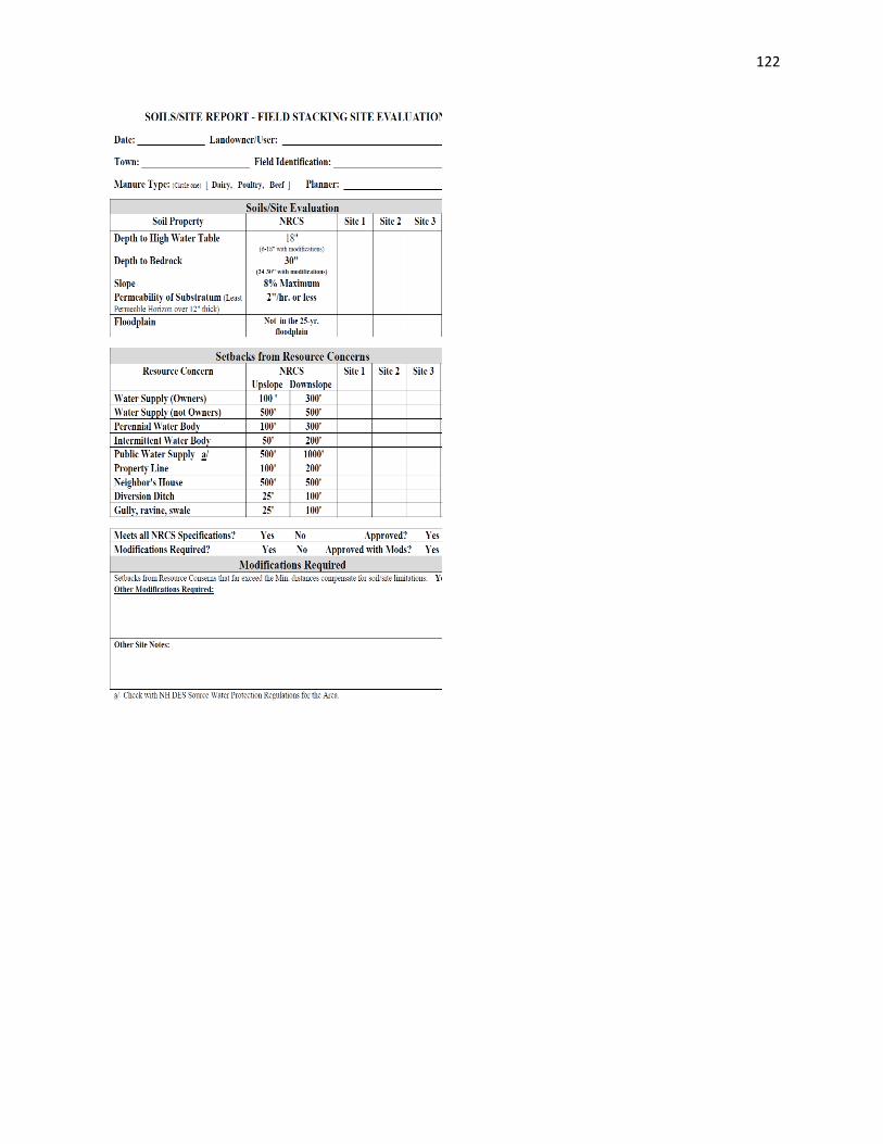
122
123
APPENDIX A
Definitions
Anti-seep Collar. A plate or membrane,
attached to the barrel running through an
embankment of a pond that prevents
seepage of water around the pipe.
Backfill. The operation of filling an
excavation after it has once been made.
Barrel. The concrete or corrugated metal
pipe of a principal spillway that passes
runoff from the riser through the
embankment, and finally discharges to the
pond's outfall.
Berm. A horizontal strip or shelf built into
an embankment or cut, to break the
continuity of a long slope, usually for the
purpose of reducing erosion, improving
stability, or to increase the thickness or
width of an embankment.
Best Management Wetlands Practice
(BMWP) for Agriculture. A proven and
accepted structural, non-structural, or
vegetative measure which permits efficient
farming operations while achieving the least
possible adverse impact upon the
environment.
Channel. A natural or artificial watercourse
which periodically or continuously contains
moving water, or which forms a connecting
link between two bodies of water.
Channel Erosion. The widening, deepening,
and headward cutting of small channels and
waterways, due to erosion caused by
flowing water.
Conservation District. A governmental
subdivision of the state of New Hampshire
established along county boundaries and
organized under RSA 430-B and defined in
Chapter 432:9.
Conservation Plan. The information
provided to a land user that includes
guidance, alternatives, and decisions as
needed to plan and apply resource
management systems consistent with field
office technical guides. Conservation plans
are a result of carrying out the planning
process with a land user. The plan contains
a record of inventories, land uses, and
treatment decisions provided to the land
user.
Conservation Practice. Need in planning
and programs for which developed. A
measure commonly used to meet a specific
carrying out soil and water conservation
standards and specifications have been
Cooperator. An individual, group of people,
or representative of a unit of government
who has entered into an understanding,
working arrangement, or cooperative
agreement with a conservation district to
work together in planning and carrying out
soil and water resources use, development,
and conservation on specific land area.
Conservation Plan Map. These include
sketch, line, photographs, etc., used in
providing and/or documenting conservation
assistance.
Considerations. Constructive and helpful
items for evaluation in the use of a BMWP.
Culvert. A closed conduit for the passage of
surface water under or over a roadway,
railroad, canal, or other impediment.
124
Dam. A barrier constructed across a
watercourse for the purpose of (1) creating
a reservoir, or (2) diverting water into a
conduit or channel.
Design storm. A rainfall event of specific
frequency and duration (e.g., a storm with a
2-year frequency and 24-hour duration)
that is used to calculate the runoff volume
and peak discharge rate for designing a
BMWP.
Dike. A temporary berm or ridge of
compacted soil that channels water to a
desired location.
Drainage. A general term applied to the
removal of surface or subsurface water
from a given area either by gravity or by
pumping.
Drainage Area. The contributing area to a
single drainage basin, expressed in acres,
square miles, or other unit of area.
Drain. Usually a pipe, ditch, or channel for
collecting and conveying water.
Emergency or Earth Spillway. A depression
in the embankment of a pond or basin that
is used to pass peak discharges greater than
the maximum design storm controlled by
the pipe spillway of the pond.
Erosion. Wearing away of land by running
water, waves, wind, ice, abrasion, and
transportation.
Filter Fabric. Textile of relatively small mesh
or pore size that is used to (1) allow water
to pass through while keeping sediment out
(permeable), or (2) prevent both runoff and
sediment from passing through
(impermeable).
Flood. Other water from a river, stream,
watercourse, ocean, lake, or body of
standing water that temporarily overflows
or inundates adjacent lands and which may
affect other lands and activities through
stage elevation, backwater and/or
increased ground water level.
Flood Control. The elimination or reduction
of flood losses by the construction of flood
storage reservoirs, channel improvements,
dikes and levees, by-pass channels, or other
engineering works.
Flood Plain. For a given flood event, that
area of land adjoining a continuous
watercourse which has been covered
temporarily by flood water.
Flood storage. Storage of water during
floods to reduce downstream peak flows.
Freeboard. The vertical distance from the
top of an embankment to the highest water
elevation expected for the largest design
storm stored. The space is required as a
safety margin in a pond or basin.
Grade. The inclination or slope of a channel,
natural ground surface, usually expressed
percentage of number of units of vertical
rise of horizontal distance conduit, etc., or
in terms of the (or fall) per unit.
Groundwater. Water filling all the
unblocked pores of underlying material
below the water table.
Headwater. (1) The upper reaches of a
stream near its source; (2) the region where
ground waters emerge to form a surface
stream; or (3) the water upstream from a
structure.
125
Hydraulics. A branch of science that deals
with practical applications of the mechanics
of water movement.
Hydrology. The science that deals with the
processes governing the depletion and
replenishment of the water resources of the
land areas of the earth.
Hydric Soil. A soil that is saturated or
flooded during a sufficient portion of the
growing season to develop anaerobic
conditions in the upper soil layers.
Impervious. A term applied to a material
through which water cannot pass, or
through which water passes with great
difficulty.
Impervious Area. Impermeable surfaces,
such as pavement or rooftops, which
prevent the infiltration of water into the
soil.
Infiltration. The downward movement of
water from the surface to the subsoil is
expressed in terms of inches/hour.
Invert. The floor, bottom, or lowest portion
of the internal cross section of a conduit.
Land Grading and Slope Stabilization. The
reshaping of existing topography in
accordance with a plan which has been
developed by engineering survey and
layout.
Level Spreader. An outlet constructed at
zero percent grade across the slope that
allows concentrated runoff to be discharged
as sheet flow at a non-erosive velocity onto
natural or man-made areas that have
existing vegetation capable of preventing
erosion.
Outlet Protection. A rock lined apron or
other acceptable energy dissipating
material placed at the outlet of a pipe or
paved channel and a stable downstream
receiving channel.
Palustrine Emergent Wetland. Non-tidal
vegetated wetlands dominated by
herbaceous plants which include wet
meadows, marshes, and fens.
Peak Discharge. The maximum
instantaneous rate of flow during a storm,
usually in reference to a specific design
storm event.
Peak Rate of Runoff. The maximum rate of
runoff during a given runoff event.
Percolation. The downward movement of
water through soil layers.
Permanent storage. The portion of a pond
or infiltration BMWP which is below the
elevation of the lowest outlet of the
structure.
Permeability. The property of a material
which permits movement of water through
it when saturated and actuated by
hydrostatic pressure.
Pervious. A term applied to a material
through which water passes relatively
freely.
Poorly drained soil. A hydric soil having the
soil characteristics as defined in Env-Ws
1014.02 (18).
Precipitation. Any moisture that falls from
the atmosphere, including snow, sleet, rain,
and hail.
Principal or Pipe Spillway. A pipe structure
normally consisting of a vertical conduit

126
(riser) and a horizontal outlet conduit
(barrel). It is used to control the water level
and the discharge from a pond or basin.
Rainfall Data. The average depth, in inches,
of rainfall occurring over a watershed or
subwatershed for a given frequency and
duration storm event.
Reach. Any length of river or channel.
Usually used to refer to sections which are
uniform with respect to discharge, depth,
area or slope, o sections between gaging
stations.
Recharge. The process by which water is
added to the zone of saturation in an
aquifer.
Recurrence Interval. The average interval of
time within which a given event will be
equaled or exceeded once. For an annual
series the probability in any one year is the
inverse of the recurrence interval. This a
flood having a recurrence interval of 100
years (100-year frequency storm) has a 1
percent probability of being equaled or
exceeded in any one year.
Release Rate. The rate of discharge in
volume per unit time from a detention
facility.
Retention. The holding of runoff in a basin
without release except by means of
evaporation, infiltration, or emergency
bypass.
Riprap. A combination of graded stone,
cobbles, and boulders used to line channels,
stabilize banks, reduce runoff velocities, or
filter out sediment.
Riser. A vertical pipe connected to a barrel,
extending from "the bottom of a pond that
is used to control the discharge rate for a
specific design storm.
Runoff. That part of the precipitation which
reaches a stream, drain, sewer, etc., directly
or indirectly for the duration of a particular
storm.
Sediment. Particles of soil and rock origin
transported, carried, or deposited by water.
Sediment Basin. A basin constructed to
collect and store sediment or other
waterborne debris.
Sheet Flow. Runoff which flows over the
ground surface as a thin, even layer, not
concentrated in a channel.
Silt Fence. A temporary barrier of geotextile
fabric attached to supporting post and
entrenched into the soil that is used · to
intercept sediment laden runoff from small
areas of disturbed soil.
Storm Runoff. The water from precipitation
running off from the surface of a drainage
area during and immediately following a
period of rain.
Straw or Hay Bale Barrier. A temporary
obstruction of straw or hay installed across
or at the toe of a slope. It intercepts and
detains small amounts of sediment from
unprotected areas of limited extent and
reduces runoff velocity down the slope.
Swale. A natural depression or wide shallow
ditch used to temporarily store, route, or
filter runoff.
Subsurface Drain. A conduit such as tile,
pipe, or plastic tubing, installed beneath the
ground surface that collects and /or
conveys excess water in the soil.

127
Surface Detention. The storm runoff
detained on the surface of the ground at or
near where the rainfall occurred, and which
will either run off slowly or infiltrate into
the soil.
Surface Infiltration. That rainfall which
percolates into the ground surface and
which therefore does not contribute
directly to the storm runoff flow.
Universal Soil Loss Equation (USLE). An
empirical equation used for estimating soil
loss and evaluating alternative land
treatment measures.
Vegetated Swale. A natural or constructed
broad channel with dense vegetation
designed to treat runoff and 'dispose of it
safely into the natural drainage system.
Swales are designed to remove pollutants
from stormwater runoff, increase
infiltration, and reduce the erosion
potential at the discharge point.
Velocity. A time rate of change of position.
In hydraulics it is usually measured in feet
or centimeters per second.
Very poorly drained soil. A hydric soil
having the soil characteristics as defined in
Env-Ws 1014.02 (17).
Wet Meadow. Herb-dominated areas
typically with non-woody vegetation less
than 3 feet in height, saturated for long
periods of time during the growing season,
but seldom flooded. Wet meadows develop
on dominantly poorly drained or poorly
drained soil conditions. Poorly drained
conditions are defined by Env-Ws 1014.02.