Embed Size (px)
Citation preview

Residual life Models for Concrete Repair - Assessment of the Concrete Repair Process
BRE Client report number Oct. 02 Draft © Building Research Establishment Ltd 2003 Commercial in confidence
Executive Summary
The size of the UK concrete repair industry was of the order of £750 million in 1990 and today is believed to be well in excess of a billion pounds - a figure that is in excess of 3% of the entire construction industry. Unplanned or unexpected maintenance and refurbishment work, such as premature failure, forms a significant proportion of this work. There are many types of reinforced concrete structures. Some structures fall within an asset management system and therefore tend to receive an ordered approach to inspection, assessment and repair. However, in many cases concrete repair is undertaken in an unstructured way, with advice to clients frequently resulting in inappropriate repair, maintenance and refurbishment of structures and the need for further additional work.
Recent initiatives within the industry, such as the Latham report ‘Constructing The Team’(1) and the Egan report ‘Rethinking Construction(2),’ have set industry targets for cost savings which have to be set in the context of whole life costing. Although whole life costing concepts are more commonly applied to the building as a whole, taking all stages from conception and design through to demolition into account, the concepts could equally be applied to help make decisions for appropriate repair strategies for existing structures.
This PII project has bought together major clients, contractors, specialist contractors, material producers and expertise in the construction process, with the ultimate aim of developing an electronic tool that will facilitate best practice in concrete repair in particular by being able to provide guidance in relation to the residual life of repair options selected. To support this process it was considered important to provide additional supporting guidance that considered the following: • Assessing the process by which concrete repairs are procured and highlighting
pitfalls or benefits of typical contractual arrangements. • Providing a framework of developments in relation to the new European Standards
that will influence the selection of repair techniques. • Presenting guidance on the appropriateness of repair techniques, including:
- Patch repair
- Electrochemical processes
- Corrosion inhibitors
- Surface treatments
This report is made on behalf of BRE. By receiving the report and acting on it, the client - or any third party relying on it - accepts that no individual is personally liable in contract, tort or breach of statutory duty (including negligence).

Residual life Models for Concrete Repair - Assessment of the Concrete Repair Process
BRE Client report number Oct. 02 Draft © Building Research Establishment Ltd 2003 Commercial in confidence
This report deals with these issues and constitutes a written milestone (sub-tasks 2.4) in the proposal.

Residual life Models for Concrete Repair - Assessment of the Concrete Repair Process
BRE Client report number Oct. 02 Draft © Building Research Establishment Ltd 2003 Commercial in confidence
Contents
1.0 Introduction 3 1.1 Why do problems occur? 3 1.2 Objectives of this study 4
2.0 A Strategy for Concrete Repair 5 2.1 Corrosion of steel in concrete 5 2.2 The problem for asset managers 5 2.3 How can the situation be improved? 6
3.0 Procuring Concrete Repair 10 3.1 The Repair Process 10 3.2 Client's Perspective 12 3.3 Consultant's Perspective 14 3.4 Contractor's Perspective 15 3.5 Advantages and Limitations of Contract Types 16
4.0 European Standards 18 4.1 General information 18 4.2 EN 1504: Products and systems for the protection and repair of concrete structures 19 4.2.1 General 19 4.2.2 Current status –2002 19 4.2.3 Parts 2 to 7 - Properties of products and systems 20 4.2.4 Part 9 - General principles for the use of products and systems 20 4.2.5 Part 10 - Site application of products, systems and QC 22 4.3 European Standards for coatings 23 4.4 European Standards for patch repair 24
5.0 Concrete Patch Repair 25 5.1 General 25 5.2 The patch repair process 27 5.2.1 Hand applied mortar 27 5.2.2 Recasting with concrete or mortar 28 5.2.3 Sprayed concrete 28 5.3 Key aspects for patch repairs 30
6.0. Electrochemical Processes 31 6.1 General 31 6.2 Cathodic protection 31 6.2.1 Types of cathodic protection 31 6.2.2 Current applied 32 6.2.3 Monitoring criteria of CP 33

Residual life Models for Concrete Repair - Assessment of the Concrete Repair Process
BRE Client report number Oct. 02 Draft © Building Research Establishment Ltd 2003 Commercial in confidence
6.2.4 Potential side effects 35 6.2.5 Recent and future developments 36 6.2.6 Key aspects for cathodic protection 36 6.3 Electrochemical chloride extraction (ECE) 37 6.3.1 General 37 6.3.2 The mechanisms 38 6.3.3 The application of ECE 39 6.3.4 Efficiency of ECE 39 6.3.5 Potential side effects 40 6.3.6 Key aspects for ECE 41 6.4 Electrochemical realkalisation 42 6.4.1 The mechanism 42 6.4.2 The application of realkalisation 43 6.4.3 Potential side effects 43 6.4.4 Key aspects for realkalisation 44
7.0 Corrosion Inhibitors 45 7.1 General 45 7.1.1 Nitrite based corrosion inhibitors 45 7.1.2 Monofluorophosphate based corrosion inhibitors 46 7.1.3 Alkanolamines and amine based corrosion inhibitors 47 7.2 Key aspects for inhibitors 47
8.0 Concrete Surface treatment 49 8.1 Introduction 49 8.2 Selection process 50 8.3 Performance assessment of coatings 52 8.4 Key aspects for concrete surface treatments 52
9 References 54 Appendix A - Tables 1A & 2A Appendix B - Simplified Procurement Routes for Concrete Repair (a) Tendered - Scheduled Rates
3
Residual life Models for Concrete Repair - Assessment of the Concrete Repair Process
BRE Client report number Oct. 02 Draft © Building Research Establishment Ltd 2003 Commercial in confidence
1.0 Introduction
The size of the UK concrete repair industry was of the order of £750 million in 1990 and today is believed to be well in excess of a billion pounds - a figure that is in excess of 3% of the entire construction industry. Unplanned or unexpected maintenance and refurbishment work, such as premature failure, forms a significant proportion of this work. There are many types of reinforced concrete structures - Table 1A (Appendix 1) provides an indication of the range that may need to be considered. Some structures fall within an asset management system and therefore tend to receive an ordered approach to inspection, assessment and repair. However, in many cases concrete repair is undertaken in an unstructured way, with advice to clients frequently resulting in inappropriate repair, maintenance and refurbishment of structures and the need for further additional work.
Recent initiatives within the industry, such as the Latham report ‘Constructing The Team’(1) and the Egan report ‘Rethinking Construction(2),’ have set industry targets for cost savings which have to be set in the context of whole life costing. Although whole life costing concepts are more commonly applied to the building as a whole, taking all stages from conception and design through to demolition into account, the concepts could equally be applied to help make decisions for appropriate repair strategies for existing structures. Factors to be considered and their implications on the required service life of reinforced concrete structures are highlighted in Table 2A of Appendix 1.
If whole life costing and service life models are to be used appropriately it is important that best practice is followed in the investigation and assessment of the structure, and in the choice of repair strategy. The amount of information required to carry out a whole life costing analysis for concrete repair is likely to be much less than that needed to carry out a comprehensive analysis on an entire building. However, each of the inputs is subject to a degree of uncertainty and, in some cases, assumptions are likely to have to be made owing to the lack of performance data.
1.1 Why do problems occur?
A significant problem for asset managers is that for the majority of existing reinforced concrete structures it is currently not economically feasible to provide an ‘early warning’ of the risk of corrosion to the steel during the ingress of aggressive species through the cover concrete. This results in a form of “reactive” corrosion monitoring that basically relies on the physical degradation of the steel reinforcement itself to indicate that the structure is exhibiting signs of distress. The reality is that some level of repair to the concrete is an inevitable element of the life history of a significant proportion of reinforced concrete structures.

4
Residual life Models for Concrete Repair - Assessment of the Concrete Repair Process
BRE Client report number Oct. 02 Draft © Building Research Establishment Ltd 2003 Commercial in confidence
Optimising the repair strategy for a structure is therefore a key factor and ensuring that the most relevant and up to date technical information is available to support the process is crucial e.g. developments in relation to British and European Standards.
However, although excellent technical guidance exists inappropriate repairs continue to be carried out and conflicts between involved parties (client/contractor/consultant) occur. Since the guidance exists, it is likely that at least some of the underlying causes of these problems are process based and probably related to the fragmentation of industry, which leads to dissipation of expertise and resources. This prevents the industry from focusing on co-ordinated actions that will improve performance, such as investment in training (to improve take-up of good practice), innovative technology and forging partnerships within the supply chain.
1.2 Objectives of this study
This PII project has bought together major clients, contractors, specialist contractors, material producers and expertise in the construction process, with the ultimate aim of developing an electronic tool that will facilitate best practice in concrete repair in particular by being able to provide guidance in relation to the residual life of repair options selected. To support this process it was considered important to provide additional supporting guidance that considered the following: • Assessing the process by which concrete repairs are procured and highlighting
pitfalls or benefits of typical contractual arrangements. • Providing a framework of developments in relation to the new European Standards
that will influence the selection of repair techniques. • Presenting guidance on the appropriateness of repair techniques, including:
- Patch repair
- Electrochemical processes
- Corrosion inhibitors
- Surface treatments
This report deals with these issues and constitutes a written milestone (sub-tasks 2.4 and 2.5) in the proposal.

5
Residual life Models for Concrete Repair - Assessment of the Concrete Repair Process
BRE Client report number Oct. 02 Draft © Building Research Establishment Ltd 2003 Commercial in confidence
2.0 A Strategy for Concrete Repair
2.1 Corrosion of steel in concrete
Prior to entering more technical discussion about concrete repair it may be useful to refresh some of the basic principles of how and why problems with reinforced concrete typically occur.
Corrosion of the steel reinforcement, which leads to cracking and spalling of the concrete covering, can present a major problem to the asset manager. Not only is there the issue of ensuring a safe, timely and cost effective repair but this has to be balanced against any disruption to the normal operating conditions of the asset e.g. closure of car parking bays.
Steel embedded in concrete is effectively prevented from corroding in most, but not all, circumstances by the formation of a protective passive layer on the steel surface. This protective layer is stabilised by the highly alkaline concrete environment [3,4]. However, if the concrete becomes contaminated with chemical species that disrupt the passive layer or reduce the concrete’s alkalinity then, providing there are sufficient concentrations of water and oxygen present, corrosion of the reinforcement can occur in areas where the passive layer no longer protects the steel.
Loss of steel passivity within concrete structures largely occurs through the action of two processes namely, carbonation and chloride contamination[4]. Corrosion of the steel reinforcement can occur through either process individually or through a combination of both. Carbonation of concrete is brought about by the reaction of the alkaline phases of the cement matrix with acidic carbonaceous gases, particularly carbon dioxide, present in the atmosphere. This reaction leads to a reduction in alkalinity of the concrete and ultimately results in the depassivation of the steel reinforcement through general dissolution of the protective passive layer. The contamination of concrete through the ingress of chloride ions, from a variety of sources such as de-icing salts, marine environments and contaminated water results in a more localised breakdown of the passive layer leading to depassivation of the steel through pitting corrosion. However, for either corrosion processes to take place and be sustained sufficient concentrations of water and oxygen are required at the areas where the passive film no longer protects the embedded steel reinforcement[4].
2.2 The problem for asset managers
A significant problem for asset managers is that for the majority of existing structures it is currently not economically possible to provide an ‘early warning’ of the risk of corrosion to the steel during the ingress of aggressive species through the cover concrete. This results in a form of “reactive” corrosion monitoring that basically relies on the physical

6
Residual life Models for Concrete Repair - Assessment of the Concrete Repair Process
BRE Client report number Oct. 02 Draft © Building Research Establishment Ltd 2003 Commercial in confidence
degradation of the steel reinforcement itself to indicate that the structure is exhibiting signs of distress.
An inability to monitor the corrosion condition of steel during the period of aggressive species penetration through the cover concrete to the depth of the steel reinforcement will cause significant problems for asset managers as this rules out possible maintenance opportunities at that time. This period might well be used to develop a more proactive maintenance schedule for the structure in question. This is especially true if accurate predictions of the risk associated with the ingress of aggressive species, such as chloride and carbonation, can be determined.
In the current climate of adopting a best value approach to the repair and rehabilitation of reinforced concrete structures ‘reactive’ corrosion monitoring alone may be insufficient if it limits the type, effectiveness, application and costs of the various repair and rehabilitation techniques available to the asset manager.
2.3 How can the situation be improved?
The corrosion process for steel reinforced concrete can be simplified into a two-stage process namely, the ‘initiation phase’ and the ‘propagation phase’. By definition the initiation phase is the time taken for conditions to become conducive to corrosion and the propagation phase is the period in which the accelerated corrosion of the steel reinforcement ultimately leads to rust staining, cracking and spalling of the cover concrete (Figure 1).
Figure 1 Simplified corrosion model (after Tuutti)
.
Intervention PointIntervention Point(Reactive maintenance)(Reactive maintenance)
Intervention PointIntervention Point(Proactive maintenance)(Proactive maintenance)C
orro
sion
of S
teel
Rei
nfor
cem
ent
T ime
M axim um P ermissible Corrosion
Corrosion Init iat ion Phase Corrosion Propagation Phase
Ingress of aggressive sp eciesthrough cover concrete
e.g. chlorides, carbonat ion
Total Service Life
Accelerated degradation ofsteel reinforcement
7
Residual life Models for Concrete Repair - Assessment of the Concrete Repair Process
BRE Client report number Oct. 02 Draft © Building Research Establishment Ltd 2003 Commercial in confidence
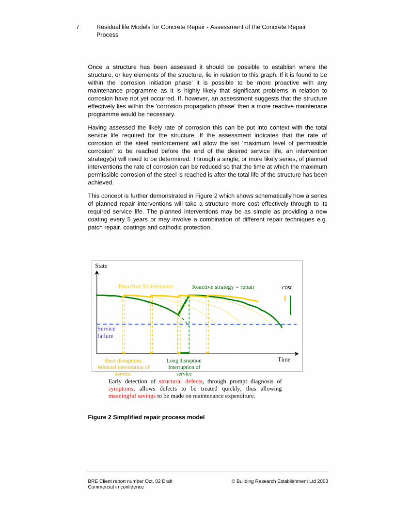
Once a structure has been assessed it should be possible to establish where the structure, or key elements of the structure, lie in relation to this graph. If it is found to be within the 'corrosion initiation phase' it is possible to be more proactive with any maintenance programme as it is highly likely that significant problems in relation to corrosion have not yet occurred. If, however, an assessment suggests that the structure effectively lies within the 'corrosion propagation phase' then a more reactive maintenace programme would be necessary.
Having assessed the likely rate of corrosion this can be put into context with the total service life required for the structure. If the assessment indicates that the rate of corrosion of the steel reinforcement will allow the set 'maximum level of permissible corrosion' to be reached before the end of the desired service life, an intervention strategy(s) will need to be determined. Through a single, or more likely series, of planned interventions the rate of corrosion can be reduced so that the time at which the maximum permissible corrosion of the steel is reached is after the total life of the structure has been achieved.
This concept is further demonstrated in Figure 2 which shows schematically how a series of planned repair interventions will take a structure more cost effectively through to its required service life. The planned interventions may be as simple as providing a new coating every 5 years or may involve a combination of different repair techniques e.g. patch repair, coatings and cathodic protection.
Figure 2 Simplified repair process model
State
Time
Servicefailure
Early detection of structural defects, through prompt diagnosis ofsymptoms, allows defects to be treated quickly, thus allowingmeaningful savings to be made on maintenance expenditure.
Reactive strategy = repairProactive Maintenance cost
Long disruptionInterruption of
service
Short disruptions.Short disruptions.Minimal interruption ofMinimal interruption of
service.service.

8
Residual life Models for Concrete Repair - Assessment of the Concrete Repair Process
BRE Client report number Oct. 02 Draft © Building Research Establishment Ltd 2003 Commercial in confidence
Information regarding the condition of the cover concrete during the initiation phase gives increased opportunity to select the correct intervention strategies to minimise the risk of corrosion (which can be more cost effective than repairing the resultant damage). However, we currently find that corrosion has already been initiated and that what is required are a series of intervention (repair) strategies during the propagation phase that will help manage the structure through to its required service life.
The often-quoted “de Sitter’s Law of Five’s” illustrates the effect of decisions made at different stages in the service life cycle of a building or structure. Paraphrasing, this might be expressed broadly as follows for a reinforced concrete structure:
£1 spent monitoring a structure to its designed service performance criteria is as effective as £5 spent in subsequent preventative maintenance in the corrosion initiation phase while carbonation and chlorides are penetrating inwards towards the steel reinforcement. In addition, this £1 is as effective as £25 spent in reactive repair and maintenance when local active corrosion is taking place and that this is as effective as £125 spent when generalised corrosion is taking place and where major repairs are necessary, possibly including replacement of complete members.
This emphasises the importance of the monitoring concept within the planning, design and specification phases of a maintenance strategy and the major influence they have upon the whole-life cost and life cycle performance of a structure. Accordingly it is very important to make the right decisions early in the life of a building or structure.
Extending the above concept, an accurate means of monitoring carbonation and chloride ingress to a concrete structure and so providing an early warning of the increased risk of reinforcement corrosion, would be extremely valuable to the asset manager.
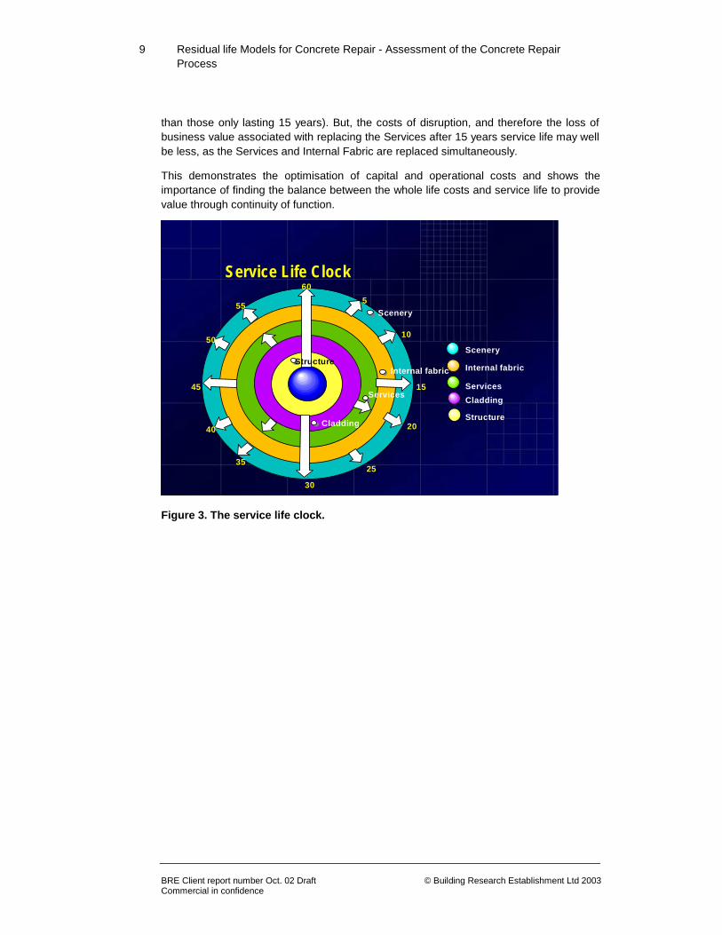
In the development of any maintenance strategy it would be as well to consider the concept of the service life clock (see Figure 3). The illustration provided is a very general one for a building as a whole but followed through demonstrates how effective a tool this can be for the asset manager and how it could easily be applied to concrete repair. The service life clock is a powerful way to explain and rationalise the importance of service life and whole life costs. It is easy to see from the clock that this building’s owners can expect minor costs every 5 years when Scenery is replaced, larger costs at 15 years when the Internal Fabric is replaced and again at 20 and 30 years for the Services and the Cladding and so on.
The power of looking at the replacement cycle as a clock is the ability to move the hands around. For example, is it possible to improve the life-care strategy or the specification of the Internal Fabric so that the anticipated service life is 20 years and replacement occurs simultaneously with the Services?
Equally, and perhaps more importantly, is it worthwhile using shorter service life components for the building Services so that replacement after 15 years, in tandem with the Internal Fabric, and after 30 years with the Cladding is expected?
In both these cases, the whole life costs of the alternative specification may not be the minimum possible (that is, the whole life costs of Services lasting 20 years may be less
9
Residual life Models for Concrete Repair - Assessment of the Concrete Repair Process
BRE Client report number Oct. 02 Draft © Building Research Establishment Ltd 2003 Commercial in confidence
than those only lasting 15 years). But, the costs of disruption, and therefore the loss of business value associated with replacing the Services after 15 years service life may well be less, as the Services and Internal Fabric are replaced simultaneously.
This demonstrates the optimisation of capital and operational costs and shows the importance of finding the balance between the whole life costs and service life to provide value through continuity of function.
Scenery
Scenery
Internal fabric
Services
Cladding
Structure
605
10
15
20
25
30
35
40
45
50
55
Scenery
Internal fabric
ServicesCladding
Structure
Service Life Clock
Figure 3. The service life clock.

10
Residual life Models for Concrete Repair - Assessment of the Concrete Repair Process
BRE Client report number Oct. 02 Draft © Building Research Establishment Ltd 2003 Commercial in confidence
3.0 Procuring Concrete Repair
3.1 The Repair Process
Although excellent technical guidance exists inappropriate repairs continue to be carried out and conflicts between involved parties (Client/Contractor/Consultant) occur. Since the guidance exists, it is likely that at least some of the underlying causes of these problems are process based and probably related to the fragmentation of industry, which leads to dissipation of expertise and resources. This prevents the industry from focusing on co-ordinated actions that will improve performance, such as investment in training (to improve take-up of good practice), innovative technology and forging partnerships within the supply chain. Alternatively owners or managers may perceive that they have a one off problem of concrete deterioration. This can result in a “low tech.” approach, which may be inadequate. If a large organisation is heavily devolved to local regions, several regions could be going up the learning curve and not sharing experience and knowledge. Concrete repair can also be part of a larger refurbishment strategy. Considering the example of a car park; there may be new ticketing machines, new lighting, drainage, repainting and new skid resistant surfaces. The concrete repair can end up being devolved down to a specialist contractor reporting through a main contractor with little knowledge or interest in the concrete repair. The specialist subcontractor may be inappropriately appointed, there may be inadequate funds, the programming may have to fit round other works.
The terms used when discussing the processes related to the supply of construction are often ill defined and used in different ways by different authors. To ensure this report is clearly understood, the following definitions are have been adopted and used: Procurement Route: A standard method of construction procurement, for example, Design and Build (D &B) and Traditional, that sets-out the specific phases of the construction process and the tasks to be completed at each stage. The procurement route is independent of the construction project.
Construction Process: The stages of the construction process that occur, from client through to the constructed product. This stages and their management is dependent on the construction project and is related to the procurement route which overlays the construction process.
Supply Chain: The connections between of individuals and groups that are involved in the construction process. This is dependent on the construction project and is related to the procurement route which overlays the supply chain. A broad overview of the relationship between these definitions is given in Figure 4.

11
Residual life Models for Concrete Repair - Assessment of the Concrete Repair Process
BRE Client report number Oct. 02 Draft © Building Research Establishment Ltd 2003 Commercial in confidence
Figure 4 – Relationship between procurement route, construction process and supply chain.
For at least the last 70 years, there have been numerous reviews of the construction industry criticising the fragmentation, the adversarial attitudes, the inefficient use of labour, the wastage of materials, the high cost of construction and the financial inefficiencies of buildings, the most recent example being “Rethinking Construction(2) ”.
The overview of supply chains in the concrete repair process, discussed in Section 2, has indicated that the supply chain is too complex and variable between projects to provide a detailed analysis of the “weak links” (non value adding steps and information gaps) which require particular attention. Mapping the repair process through the use of procurement routes and supply chains serves only to identify those points in the process at the highest level where problems have or potentially may occur.
Any strategy developed to improve the repair process must be generic to the industry to enable uptake and ensure the desired reduction in the number of problems. As a result it was considered that an approach to minimising problems should be sought, a key factor of which was that it was applicable to any repair project irrespective of the complexities of the supply chain that may actually be involved. With this in mind the project has analysed the repair process in relation to the contract type and the associated obligations of the involved parties.
The following sections consider the role or perspective of the Client, Consultant and the Contractor within the framework of their responsibilities within the following four main types of contract;
• Traditional 'Low cost' schedule of rates tender.
Traditional Procurement Route
Brief Design Construct Use
Construction Process
Brief 1st Design Refine Brief 2nd Design Specify Materials
Supply Chain
Brief 1st Design Refine Brief 2nd Design Specify Materials
Client
Client’s Agent Chief Designer
Design Team
Client’s Agent
Materials Specifiers
Quantity Surveyor
Materials Suppliers
Traditional Procurement Route
Brief Design Construct Use
Construction Process
Brief 1st Design Refine Brief 2nd Design Specify Materials
Supply Chain
Brief 1st Design Refine Brief 2nd Design Specify MaterialsBrief 1st Design Refine Brief 2nd Design Specify Materials
Client
Client’s Agent Chief Designer
Design Team
Client’s Agent
Materials Specifiers
Quantity Surveyor
Materials Suppliers
12
Residual life Models for Concrete Repair - Assessment of the Concrete Repair Process
BRE Client report number Oct. 02 Draft © Building Research Establishment Ltd 2003 Commercial in confidence
• Fixed price - 'Lump sum' tender/bid.
• Best price/value tender/bid.
• True partnering (no price bid involved, typically 3 parties involved).
In a summary at the end, the 'pros' and 'cons' of each party's obligations within the contract types is presented in an attempt to draw out the principal non value adding steps and gaps that often occur in the concrete repair process and that can ultimately lead to otherwise avoidable conflict.
3.2 Client's Perspective
In the majority of situations where repair, maintenance and/or monitoring are required for a reinforced concrete structure the client quite simply desires a simple cost effective solution to a problem. This may be translated as meaning that the cheapest solution in the quickest possible time is required. However, when considering sustainability and whole life issues this may not be the most sensible and/or economic long-term option for a structure.
Clients should take responsibility not only for funding the necessary repairs and maintenance to a structure under their ownership, but also for the overall strategy of achieving the desired service life. It may be that specialist advice is required to help develop that strategy.
A proactive approach, whereby the funds required to operate a scheduled maintenance programme, is likely to produce a better return over the service life of a structure than a reactive approach where each problem is dealt with on an ad-hoc basis. The provision of such funding is currently still likely to be a constraint to this type of approach being universally adopted. However, it may well be worth considering a risk driven strategy, whereby a phased approach to repair and maintenance is developed. Adopting a phased strategy will mean that when limited funding is available, the technical solution is not necessarily compromised and the most pressing work is carried out properly first.
Successful concrete repair requires the identification and treatment of all latent and active distress. As such the repair process will normally result in the structure being improved. In standard lease agreements the tenant is responsible for maintaining the structure in its condition at the beginning of the tenancy whilst the owner is responsible for improvements. Therefore when a lease has nearly run out and if there is no desire to extend or renew, there is a strong temptation to carry out as little maintenance or repair as is possible.
Taking this view may well rule out many valid maintenance and repair options and while the cost of the works carried out in the short term may be low, the value of that work to the longer term serviceability of the structure may also be low. There is a requirement therefore to address this issue within lease agreements to ensure that the structure is maintained efficiently.

13
Residual life Models for Concrete Repair - Assessment of the Concrete Repair Process
BRE Client report number Oct. 02 Draft © Building Research Establishment Ltd 2003 Commercial in confidence
Prior to the commission of any work it is important that a meaningful survey of the structure is carried out. Again, clients should be aware that value is not always directly proportional to cost. Further along the process of design and construction the consultant producing the specification or the contractor carrying out the work will require good quality, accurate survey data. A company (that may be the contractor or consultant involved in the specification and/or repair works in many instances) competent in carrying out the type of specialist survey required should be employed.
Clients should also be aware of the risks involved in allowing undue time to elapse between the survey and the recommended repair works. These risks could manifest themselves as:
• Presenting a danger to the public through materials falling from unsound structures.
• The structure continues to deteriorate and the repair will become more expensive as time passes.
• The erection of expensive 'temporary' containment works can consume large amounts of money without actually addressing the underlying problems.
• When costing out repair works several years later, the original survey data will be invalid and require repeating.
In trying to achieve the best value solution to a problem where repair and maintenance options to a reinforced structure are involved, clients may also benefit by considering the type of contract under which the work is let.
The traditional route is to pursue a tendered contract with a scheduled rate for each type of repair carried out. This may appear to offer benefits to the client in terms of providing a low price through competition, although the final cost of the work may be far higher if the full extent of the repairs necessary is not sufficiently identified at the tender stage.
A more recent type of contract is the lump sum contract. This has been gaining favour since the early 1990’s and minimises the risk to the repair contractor of ‘underestimating’ the work necessary and therefore can often result in a lower cost solution to the client. Care still needs to be taken to ensure there are no ambiguities within the specification to prevent additional costs being added at a later date.
Many of the problems with lump sum and tendered contracts can be overcome through the use of either partnering arrangements or negotiated contracts. In these circumstances both the client and the contractor have an interest in not only the successful completion of a repair or maintenance programme but also in attempting to find the most appropriate and cost effective technical solution.
Another form of contract that is now becoming common with concrete repair is that of 'best price/value' contracts. Here the client issues Client’s Requirements documentation/ performance specifications, but a weighting is applied to the 'quality' of the bid such that in theory the lowest price will not necessarily always win the work.
14
Residual life Models for Concrete Repair - Assessment of the Concrete Repair Process
BRE Client report number Oct. 02 Draft © Building Research Establishment Ltd 2003 Commercial in confidence
It is advisable that the client considers the options carefully before selecting a consultant and contractor to specify and carry out the work. Furthermore, the clerk of works appointed by the client should be experienced in concrete repairs. This should not be considered as merely a supervisory role since it requires specialist knowledge of the procedures to be adopted.
3.3 Consultant's Perspective Consultants frequently find themselves sandwiched in the middle between the client and the contractor in a position where it is impossible to keep both sides happy. All too often there is a perception that the client does not really know what he/she wants and that the client wants the job completed for an unrealistically low price and to an unachievable timescale. This situation may be compounded by the perception of having to deal with contractors who are, on the one hand, unreliable, charge too much and try to get away with a minimal standard of work, or on the other hand, are very competitive and competent but escalate the scope of the work to increase their profitability.
Consultants play a vital role in the repair and maintenance process but their success in any given situation is likely to be closely related to the availability of crucial information.
To properly serve the client it is important that all the relevant information required is available as near as possible to the beginning of a project. For example, detailed drawings, photographs or survey information will all provide valuable background data that will help ensure that any strategy developed will be appropriate and not based on a 'best guess' basis of what the situation is likely to be. Larger clients, for example local authorities, could help by ensuring that their records are well organised and that information can be easily retrieved when required.
To maximise the achievements of the contractor, consultants have to be able to transfer all the available information in a logical, readily digestible format. Their requirements need to be carefully planned and presented to the contractor to allow them sufficient time to fully understand the situation.
It is more common for concrete structures to be maintained and repaired rather than demolished. On balance the repair and maintenance work tends to be more cosmetic rather than of a structural nature. It is likely that a combination of strategies or techniques may be used on any one structure, hence thorough planning is very important and this should be reflected in the project specification.
Part of the consultants brief usually involves the preparation of the specification for the work to be carried out which will subsequently be passed on to the contractors to price. In relation to the preparation of specifications a number of points have been identified for consideration:
• A material or product based specification would generally be considered adequate, but it must be supported by a recognised quality assurance or certification scheme. However, the specification of specific materials is often

15
Residual life Models for Concrete Repair - Assessment of the Concrete Repair Process
BRE Client report number Oct. 02 Draft © Building Research Establishment Ltd 2003 Commercial in confidence
deemed to be unacceptable by clients, particularly local authorities, because it conflicts with perceived competition.
• Performance based product specifications are a positive move forwards, as long as the specification is applied i.e. materials that can not demonstrate compliance are excluded.
• It is essential to include workmanship clauses in any performance based specification to ensure the required standard of repair is achieved as poor workmanship and poor specification are common causes of failure for concrete repairs.
• Where conformance testing is required the specification should be carefully written to address all the important issues. For example, it is important to ensure that cover depths are achievable bearing in mind the aggregate size specified.
• The requirement for quality assurance schemes within specifications is seen as a positive move towards minimising problems during the work.
3.4 Contractor's Perspective In an ideal world all the repair work on a structure would be tackled as part of a planned maintenance schedule. The client would fully understand the nature of the required works and would have briefed his consultant with all the relevant information required. This would allow a well-organised and appropriate specification, supported by an accurate estimation of the work required, to be passed to the contractor. The repair contractor would then have sufficient time to prepare a well considered and accurately priced tender that the client and consultant would consider on a combination of technical merit and price, rather than simply on the basis of price alone.
The reality, however, is that the work is commonly not properly planned and scheduled in advance and/or an unexpected failure occurs on a structure. Contractors are frequently left in the unenviable position of having to prepare a bid for the remedial work in a very short space of time, often based on only limited information. It is not surprising, therefore, that mistakes occur (which are often very costly) and that the contractor/consultant/client relationship deteriorates. A number of factors should be considered in order to aid the design and construction process and to minimise the potential of a problem arising:
• Provide the contractor with a reasonable tender period in which to prepare the bid.
• Provide a reliable estimate of the amount of work required. This often requires that an independent survey be carried out in order to draw up an accurate bill of quantities that should then be set out in a logical and easily understandable fashion in order to minimise disputes at a later date.
• The adoption of a standardised format for measurement methods.
16
Residual life Models for Concrete Repair - Assessment of the Concrete Repair Process
BRE Client report number Oct. 02 Draft © Building Research Establishment Ltd 2003 Commercial in confidence
• Consideration of tenders by clients/consultants on their technical merits and benefits to the whole life performance of a structure and not just price.
• Consideration by clients of entering into term contracting or partnering agreements with specialist contractors with a proven track record, as this may actually generate a better value-for-money service. Lists of contractors, consultants and suppliers, are available from trade associations such as CRA (Concrete Repair Association), CPA (Corrosion Prevention Association), SCA (Sprayed Concrete Association) and the Concrete Society.
• Appreciation by all involved that the conditions and requirements of a construction site can change as the work progresses due to circumstances unforeseen in the original proposal or specification.
• It is important for the smooth running of the repair/maintenance contract that the client and his consultant understand the details of the repair methodology adopted.
3.5 Advantages and Limitations of Contract Types
Table 1 summarises the issues raised in the preceding sections to provide a balanced assessment of the contract types under which the majority of concrete repairs are procured. It would be considered that a greater understanding of the selected process from the outset by all parties involved would significantly reduce the difficulties experienced later in the contract.

17
Residual life Models for Concrete Repair - Assessment of the Concrete Repair Process
BRE Client report number Oct. 02 Draft © Building Research Establishment Ltd 2003 Commercial in confidence

18
Residual life Models for Concrete Repair - Assessment of the Concrete Repair Process
BRE Client report number Oct. 02 Draft © Building Research Establishment Ltd 2003 Commercial in confidence
4.0 European Standards
European Standards will have a profound impact on the concrete repair industry and its clients. For the first time there will be standard requirements for selection of repair techniques and repair products. In the next couple of years industry will be able to specify appropriate repair treatment and product requirements of concrete repair products by CEN standards, and CE marking will be used by manufacturers.
The CEN Standard for materials for the protection and repair of concrete is EN 1504, of which there will eventually be ten parts under the general title of; Products and systems for the protection and repair of concrete structures - Definitions, requirements, quality control, evaluation of conformity.
This section is intended to provide an overview of the latest information on developing standards. The nature of the contents will limit the relevance of this section to about 2003.
4.1 General information The Committee European Normalisation (CEN) is responsible for developing European Standards (European Norm - EN) for products and procedures, such as those used in concrete repair. Once approved, these standards are issued by the National Standards body within each member state and prefixed by the issuer (ie BS EN for the UK). The issuing country will add their front cover and may include a foreword introducing the standard. There are several stages in the development of an EN as follows:
• EN Harmonised – A harmonised standard meets certain legal requirements laid out by CEN and allows goods that comply to be CE marked. This gives goods the right to be traded within EC member countries without trade restrictions.
• EN – A non-harmonised standard is recognised as the sole standard within the EC and national standards covering the same goods or procedures are withdrawn. The addition of a standard annex (Annex Z) converts it to a harmonised standard.
• prEN – This is a provisional standard issued for public comment. Once the comments have been taken into account the standard is voted on by the relevant national committees for publishing as a full EN. Until this has happened National Standards for the goods or procedures prevail, where they are already in existence.
• ENV – These are voluntary pre-standards often prefixed with DD (draft for development). This route is most often taken when there is insufficient information available to create a full standard. They may be issued by National Authorities (e.g.

19
Residual life Models for Concrete Repair - Assessment of the Concrete Repair Process
BRE Client report number Oct. 02 Draft © Building Research Establishment Ltd 2003 Commercial in confidence
BS DD ENV) and will have a limited life span of between 3 and 5 years after which time the standard will be withdrawn or sufficient information developed for conversion to EN.
Most standards contain two types of clause, normative and informative. Normative ones are mandatory whilst informative ones are for clarification only.
4.2 EN 1504: Products and systems for the protection and repair of concrete structures
4.2.1 General EN 1504 is entitled, 'Products and systems for the protection and repair of concrete structures - Definitions, requirements, quality control, evaluation of conformity'. This covers a number of aspects that specifically relate to the design and execution of repair and remediation treatments. The standard will fulfil a number of functions including:
• To specify minimum performance levels so that a product can attain approval for sale in Europe (the CE mark) for a given application.
• To remove technical barriers to trade, with a repair product being deemed to satisfy specification requirements by meeting the defined performance levels, whatever the country of manufacture.
• To provide reference to identification tests, by which a product may be sampled, checked and confirmed to be in accordance with a manufacturer's specification.
• To provide reference to relevant performance tests, by which the designer/specifier can select the most appropriate product for the repair.
• To provide standardised approaches for the design and execution of repairs to concrete structures.
There will be ten parts of EN 1504 as listed in Table 2.
4.2.2 Current status –2002 Part 1 has been issued as a full EN and covers the scope and general definitions. Technical performance requirements for the materials used, such as, mortars and coatings are contained in Parts 2 - 7 with test methods given in new test standards that are currently being drafted and finalised. Part 9 outlines the process of specifying protection and repair of concrete and is available as a draft for development (DD ENV 1504-9:1997). It is currently being reviewed prior to conversion to a full European Standard, and is likely to be issued as such in 2002. When this occurs, public purchasers will be expected to specify repairs by reference to this standard approach. Part 10 (available as a draft) deals with site aspects of protection and repair, such as substrate cleaning and preparation, and testing of completed works. It is anticipated that the majority of the parts will be issued by the end of 2002.

20
Residual life Models for Concrete Repair - Assessment of the Concrete Repair Process
BRE Client report number Oct. 02 Draft © Building Research Establishment Ltd 2003 Commercial in confidence
STANDARD REFERENCE
STANDARD
TITLE
BS EN 1504-1
prEN 1504-2
prEN 1504-3
prEN1504-4
prEN1504-5
prEN1504-6
prEN1504-7
prEN1504-8
DDENV1504-9
prEN1504-10
General Scope and Definitions Surface Protection Systems Structural and Non- Structural Repair Structural Bonding Concrete Injection Grouting to Anchor Reinforcements or to Fill External voids Reinforcement Corrosion Prevention Quality Control and Evaluation of Conformity General Principles for the Use of Products and Systems Application of Products and Systems and Quality Control of the Works
Table 2 -Content of European Standard EN1504 Products and systems for the protection and repair of concrete structures
4.2.3 Parts 2 to 7 - Properties of products and systems Parts 2 to 7 detail the performance test requirements for the repair methods given in Part 9. Supporting test methods are given in other CEN and ISO standards. These are normally selected and adapted, in order of priority, from existing CEN, ISO, National and other standards sources.
The requirements of products and systems are defined in terms of their typical uses, as, for all intended use (AIU) and for certain intended uses (CIU). In the Standard, the requirements are not explicitly linked with the environmental or loading conditions to which the protection and repair measures will be exposed but these must be taken into account when specifying the performance testing.
4.2.4 Part 9 - General principles for the use of products and systems The principles for protection and repair are dealt with in Part 9 - General principles for the use of products and systems. When confirmed as a full European Standard its use will become effectively mandatory for a wide range of projects. There will therefore be significant advantages for those who gain experience with Part 9 by applying it immediately. For the first time, specifiers will have standardised guidance on how to select repair products based on the repair application required. The proposed selection strategy is shown in Figure 5.

21
Residual life Models for Concrete Repair - Assessment of the Concrete Repair Process
BRE Client report number Oct. 02 Draft © Building Research Establishment Ltd 2003 Commercial in confidence
Minimum requirements for assessment of defects and their
causes
• Present condition • Original design approach • Environment and contamination • Conditions during construction
• Conditions of use • History of structure • Future use
Choose Option
• Do nothing for a certain time • Re-analyse structural
capability • Prevent or reduce further
deterioration • Improve, strengthen or
refurbish all or part • Reconstruct all or part • Demolish all or part
• Intended use, design life and service life • Required performance characteristics • Likely long-term performance of protection or repair works • Opportunities for additional protection and monitoring • Acceptable number and cost of future repair cycles • Cost and funding of alternative protection or repair options,
including future maintenance and access costs • Properties and methods of preparation of existing
substrate • Appearance of protected or repaired structure
Choose Principle appropriate to the option chosen
Defects in Concrete
1. Protection against ingress 2. Moisture control
Reinforcement corrosion
Preserving or restoring passivity
3. Concrete restoration 4. Structural strengthening 5. Physical resistance 6. Resistance to chemicals
Increasing resistivity Cathodic control Cathodic protection Control of anodic areas
Choose a Method
• Appropriate to type and cause or combination of causes and to the extent of the defects
• Appropriate to future service conditions • Appropriate to protection or repair option chosen
• Compliance with the Principle chosen • Availability of products and systems which comply with the
EN 1054 series or any other relevant EN or European Technical Approval
Choose materials which comply with the standard
• Characteristics for all intended uses • Characteristics for certain intended uses • Characteristics may be considered for specific
applications
Set out inspection and maintenance requirements
• Record of the protection or repair works which have been carried out
• Instructions on inspection and maintenance to be undertaken during the remaining design life to the repair
part of the concrete structure
Figure 5 - Overview of DD ENV 1504-9: 1997

22
Residual life Models for Concrete Repair - Assessment of the Concrete Repair Process
BRE Client report number Oct. 02 Draft © Building Research Establishment Ltd 2003 Commercial in confidence
A range of deterioration processes is identified in Part 9 together with methods which might be used to protect against or repair the effects. There are also notes for guidance regarding the methods included but this does not exclude the use of other methods not mentioned.
Specific applications that are excluded from the standard are:
• structures damaged by fire,
• any purpose other than protection or repair of concrete,
• defects of existing post-tensioned systems.
However, the general principles can still be applied to such applications.
Minimum requirements for assessment of defects and their causes are given but Part 9 clearly states that it is not intended to be a guide for inspecting and assessing the condition of concrete structures.
The strategic options for maintenance, and repair that are listed in the standard range from doing nothing, to complete demolition of the structure. When selecting an appropriate strategy a number of factors have to be considered such as, the cost of alternative protection and repair options, future maintenance and repair cycles, and the required future functionality of the structure. Further information on these options and an illustration of the process of selecting them is provided in Section 6.6.
4.2.5 Part 10 - Site application of products, systems and QC Part 10 of the standard will specify how the execution of the protection and repair is carried out. Certain methods covered by Part 9 will not be covered by Part 10 since they are addressed in other EN or European Technical Approval. These are as shown in Table 3.
Version 4 of pr EN 1504 -10 was circulated for public comment with a deadline of 31/10/99, further comments have been made in the lead up period to formal vote early in 2001.

23
Residual life Models for Concrete Repair - Assessment of the Concrete Repair Process
BRE Client report number Oct. 02 Draft © Building Research Establishment Ltd 2003 Commercial in confidence
REFERENCE
DESCRIPTION OF METHOD
1.3
1.5
1.6
1.7
2.3
2.4
3.4
4.7
7.3
7.5
10.1
11.3
Locally bandaged cracks Transferring cracks into joints Erecting external panels Applying membranes Sheltering or overcladding Electrochemical treatment Replacing elements Prestressing ( post tensioning ) Electrochemical realkalisation carbonated concrete Electrochemical chloride extraction Applying electrical potential Applying inhibitors to the concrete
Table 3 – Methods not included in Part 10
4.3 European Standards for coatings
The EN 1504 series will provide important guidance on the selection of coatings for concrete, performance requirements and the required mandatory tests for determining performance characteristics. Part 2 is the section specifically dealing with coatings and the classification system contained within it is expected to become a full European Standard during 2001. It will present requirements for coatings on concrete for a particular use, including car parks, floors, buildings, bridges, etc.

24
Residual life Models for Concrete Repair - Assessment of the Concrete Repair Process
BRE Client report number Oct. 02 Draft © Building Research Establishment Ltd 2003 Commercial in confidence
The principles covered of most relevance to coatings are:
1 Protection against ingress (PI) 1.1 Impregnation. 1.2 Surface coating with and without crack bridging ability. 1.3 Locally bandaged cracks. 1.4 Filling cracks. 1.5 Transferring cracks into joints. 1.6 Erecting external panels. 1.7 Applying membranes.
2 Moisture Control (MC ) 2.1 Hydrophobic impregnation. 2.2 Surface coating. 2.3 Sheltering or over cladding. 2.4 Electrochemical treatment.
5 Physical Resistance (PR) 5.1 Overlays or coatings. 5.2 Impregnation.
6 Resistance to chemicals (RC) 6.1 Overlays or coatings. 6.2 Impregnation.
8 Increasing Resistivity (IR) 8.1 8.2
Limiting moisture content by hydrophobic impregnation. Limiting moisture content by coatings.
4.4 European Standards for patch repair
The advent of European Standards for the protection and repair of concrete should establish a benchmark for performance in laboratory tests, with a set of standard methods being used. Site testing should also become more standard. Therefore, in principle, there should be more good quality information available about certain aspects of the performance of repairs, which will provide a better basis for correlating performance in practice with the results of laboratory testing.
Part 3 is the section that deals specifically with patch repairs and the classification system is anticipated to be issued before the end of 2002. The scope of the standard covers products and systems to restore and/or to replace defective concrete and to protect reinforcement, necessary to extend the service life of a structure exhibiting deterioration. The principles covered of most relevance to patch repair of concrete, are:
3 Concrete Restoration (CR) 3.1 Applying mortar by hand. 3.2 Recasting with concrete. 3.3 Spraying concrete or mortar.
4 Structural Strengthening (SS) 4.1 Adding or replacing embedded or external reinforcing steel bars. 4.2 Installing bonded rebars in preformed or drilled holes in the concrete 4.3 Plate bonding.
7 Preserving or restoring passivity (RP)
7.1 Increasing cover to reinforcement with additional cementitious mortar or concrete.
7.2 Replacing contaminated or carbonated concrete.
25
Residual life Models for Concrete Repair - Assessment of the Concrete Repair Process
BRE Client report number Oct. 02 Draft © Building Research Establishment Ltd 2003 Commercial in confidence
5.0 Concrete Patch Repair
By far the most common repair technique is the application of concrete patches to damaged or deteriorated concrete. Furthermore, when other remediation techniques are being applied in order to limit the extent of on-going corrosion mechanisms or to prevent their re-occurrence, patch repairs are also used to reinstate the spalled or delaminated areas of concrete.
This chapter covers the concrete patch repair process, including hand-application, spray-application and re-casting. The key issues to be considered are highlighted in Section 5.3. A DETR research project, contract No CC1487 – Improved Quality of Patch Repairs, carried out at BRE and completed in March 2001. Readers should also refer to EN 1504, particularly Parts 3, 7, 9 and 10.
5.1 General After identifying the source of the deterioration, the next step in designing a successful concrete repair is to consider its principal objective which will generally be to restore or enhance one or more of the following: durability, structural strength, function or appearance(5). Of these, the restoration of durability is usually the main requirement of a repair. There are three main techniques for applying a patch repair:
• Hand applied.
• Recast.
• Sprayed concrete.
Once the objective for the repair has been identified, appropriate repair materials and application techniques should be selected after addressing the following points:
• Remedying of the cause of the deterioration.
• The quantity and size of the repairs.
• Permanent vs. temporary repair.
• Availability of repair materials and methods.
• The service environment for the repair material.
• The economic viability of each method.
• Time available.
• Access.
26
Residual life Models for Concrete Repair - Assessment of the Concrete Repair Process
BRE Client report number Oct. 02 Draft © Building Research Establishment Ltd 2003 Commercial in confidence
• Noise, dust and vibration.
• Disposal of any waste products.
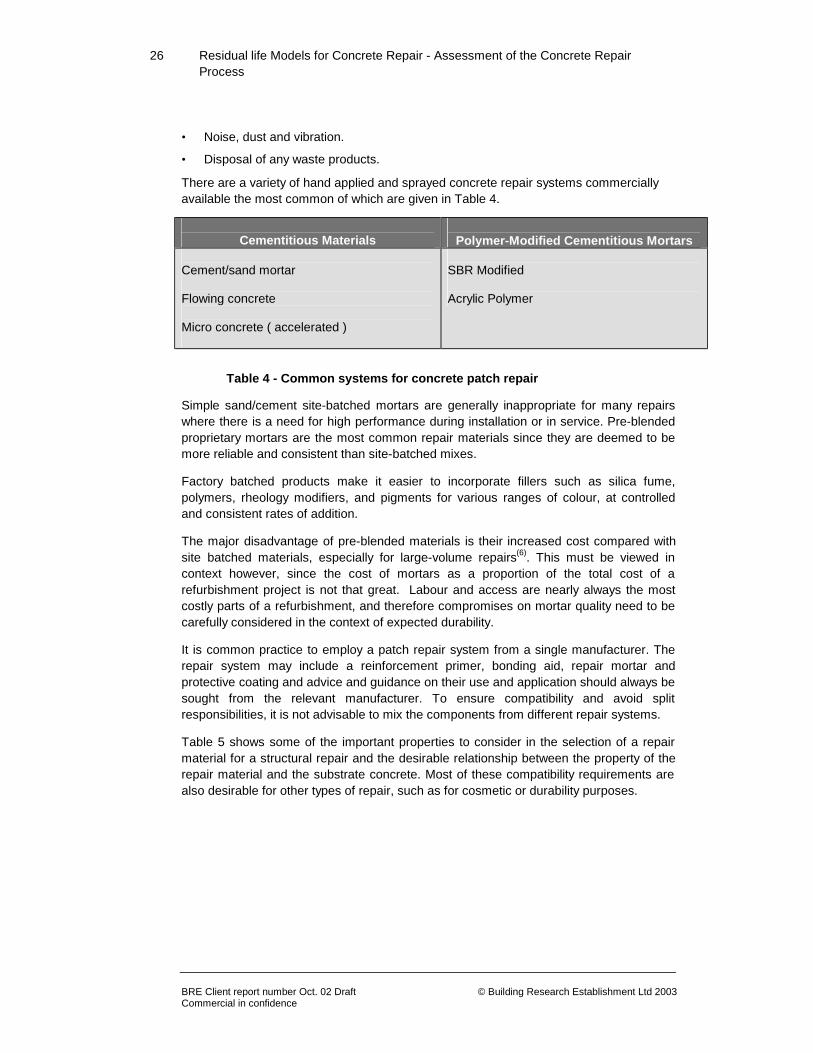
There are a variety of hand applied and sprayed concrete repair systems commercially available the most common of which are given in Table 4.
Cementitious Materials
Polymer-Modified Cementitious Mortars
Cement/sand mortar Flowing concrete Micro concrete ( accelerated )
SBR Modified Acrylic Polymer
Table 4 - Common systems for concrete patch repair
Simple sand/cement site-batched mortars are generally inappropriate for many repairs where there is a need for high performance during installation or in service. Pre-blended proprietary mortars are the most common repair materials since they are deemed to be more reliable and consistent than site-batched mixes.
Factory batched products make it easier to incorporate fillers such as silica fume, polymers, rheology modifiers, and pigments for various ranges of colour, at controlled and consistent rates of addition.
The major disadvantage of pre-blended materials is their increased cost compared with site batched materials, especially for large-volume repairs(6). This must be viewed in context however, since the cost of mortars as a proportion of the total cost of a refurbishment project is not that great. Labour and access are nearly always the most costly parts of a refurbishment, and therefore compromises on mortar quality need to be carefully considered in the context of expected durability.
It is common practice to employ a patch repair system from a single manufacturer. The repair system may include a reinforcement primer, bonding aid, repair mortar and protective coating and advice and guidance on their use and application should always be sought from the relevant manufacturer. To ensure compatibility and avoid split responsibilities, it is not advisable to mix the components from different repair systems.
Table 5 shows some of the important properties to consider in the selection of a repair material for a structural repair and the desirable relationship between the property of the repair material and the substrate concrete. Most of these compatibility requirements are also desirable for other types of repair, such as for cosmetic or durability purposes.

27
Residual life Models for Concrete Repair - Assessment of the Concrete Repair Process
BRE Client report number Oct. 02 Draft © Building Research Establishment Ltd 2003 Commercial in confidence
PROPERTY
IDEAL RELATIONSHIP OF REPAIR MATERIAL TO CONCRETE
SUBSTRATE Shrinkage strain Creep coefficient ( for repairs in compression ) Creep coefficient ( for repairs in tension ) Thermal expansion of coefficient Modulus of elasticity Poisson's ratio Tensile strength Adhesion Porosity and resistively Chemical reactivity
Lower Lower Higher Same Same Same Higher Higher Same Lower
Table 5 – Ideal compatibility requirements for patch repair materials
5.2 The patch repair process
The patch repair process consists of the following key stages:
• Removal of damaged concrete.
• Substrate and steel preparation.
• Application of the repair mortar.
The removal of the damaged concrete and substrate and steel should be carried out in accordance with current best practice. The application of the repair will be through one of the following processes.
5.2.1 Hand applied mortar Carbonation on a building facade usually requires relatively small, isolated repairs and so lends itself to hand-applied patch repairs.
The mortar or concrete should be mixed according to the manufacturer’s instructions. The mortar is then worked around and behind the reinforcement by hand. The thickness of each layer built up and the application procedure can vary greatly depending upon the material used and the orientation of the surface being repaired.
A typical procedure is to apply layers of 25-50 mm thick on vertical work and 20-30 mm thick for overhead areas. Care should be taken when applying additional layers to ensure that the previous mortar has gained sufficient strength, but has not set. If the following layer is delayed then the surface can be scoured and dampened with water before the next layer is applied, or a bonding bridge applied. The repair can be finished with a trowel using the surrounding concrete as a guide.

28
Residual life Models for Concrete Repair - Assessment of the Concrete Repair Process
BRE Client report number Oct. 02 Draft © Building Research Establishment Ltd 2003 Commercial in confidence
5.2.2 Recasting with concrete or mortar This technique is usually most suitable for large-volume repairs or where large areas of dense reinforcement are present. Access for vibration is often a problem and so flowable grouts and self-compacting proprietary micro-concretes have been developed to minimise the vibration required.
Where bonding agents are used the shutters and pouring sequence have to be carefully designed so that they can be rapidly positioned before the bonding agent dries. The concrete or mortar has to be carefully placed to avoid the entrapment of air. Pumping is usually employed although conventional ‘letter box’ type shutters can be used on smaller pours. When pumping, the delivery hose should be at a low position in the pour to allow the air to be displaced and should be steadily raised as the pour height increases. However, in overhead pours this is more difficult. Additional concrete may need to be broken out and a second pipe used in the highest part of the broken out area to allow the entrapped air to escape as shown in Figure 6.
Figure 6 - Pumped concrete repair on soffit
5.2.3 Sprayed concrete Sprayed concrete has been successfully used in many applications, including: bridge soffits, beams, parapets and abutments; steel and reinforced concrete framed buildings; cathodic protection overlays; cooling towers; industrial chimneys; tunnels; water-retaining structures; jetties, sea walls and other marine structures(7). It is often chosen to repair fire-damaged structures as it can be applied quickly and economically to the large areas typically involved.
Sprayed concrete can offer several advantages when compared with recasting or hand-applied repairs including;
• reduction or elimination of formwork.
• the construction of free-form profiles.

29
Residual life Models for Concrete Repair - Assessment of the Concrete Repair Process
BRE Client report number Oct. 02 Draft © Building Research Establishment Ltd 2003 Commercial in confidence
• efficient construction (due to rapid placement of thin layers).
• thicker layer build.
• good bond to substrate(8).
Sprayed mortar or micro-concrete can be applied via two methods:
• Dry process.
• Wet process.
In the dry process, the dry constituents (i.e. sand, aggregate, cement, additives) are batched together on-site, or pre-bagged, before being conveyed by compressed air down the delivery hose to the nozzle, where pressurised water is introduced and the mix projected into place. In the wet process, the constituents are batched and mixed together before being fed (wet) into the delivery equipment or pump. The mix is then conveyed under pressure to the nozzle, where compressed air is injected to project the mix into place. With the dry process the water/cement ratio and the concrete quality are dependent upon operator skill and site supervision.
Sprayed concrete can be specified using either the designed mix or prescribed mix approach. A designed mix is designed by the contractor to achieve the specified compressive strength and/or other properties and is preferable for sprayed concrete as the contractor is free to select constituents to produce the best pumping performance. A specification and accompanying guidelines have been produced by EFNARC(9,10). The choice of equipment should always be left to the contractor, although restrictions may need to be applied in some situations.
It is recommended(11) that sprayed micro-concrete, when used as an overlay, should be reinforced with a mesh when the thickness exceeds 50 mm and that the minimum reinforcement diameter should be 3 mm. The arrangement of the reinforcing bars and mesh should enable the sprayed micro-concrete to fill behind and fully encase the steel otherwise voids behind the steel can occur.
Layers of bars and mesh should also be staggered for similar reasons and should not be spliced or laid together. Wire mesh is often used to limit the development and depth of cracks resulting from shrinkage and temperature stresses over large areas.
When formwork is required it is generally similar to that for conventionally cast concrete. Forms and temporary screed boards are used to help to spray corners and edges, and construction and expansion joints. These are secured a certain distance from the substrate to allow the rebound and compressed air to escape beneath and are then removed prior to spraying the adjacent face. The force of the sprayed concrete can vibrate the formwork and disturb the build up of material, therefore particular care should be taken to avoid this during fixing. Guide strips and ground (piano) wires help when cutting back the material to produce surface profiles. Plastic or metal depth gauges can also be effective, although care has to be taken not to affect the integrity of the material.

30
Residual life Models for Concrete Repair - Assessment of the Concrete Repair Process
BRE Client report number Oct. 02 Draft © Building Research Establishment Ltd 2003 Commercial in confidence
The quality of a sprayed concrete repair is very operator dependent and bad quality repairs are very often the result of poor spraying. The Construction Industry Training Board (CITB) in conjunction with the Sprayed Concrete Association has therefore set up training and certification schemes in the UK. It is strongly recommended that personnel competence and its verification should be a specified requirement in the contract documents.
The preferable finish is a natural or 'as shot' finish as the material has not been disturbed by finishing and will possess its best possible characteristics in terms of bond, strength and durability(12). A textured finish can also be obtained if required by the use of a trowel, float or brush. Flash coats are also common to either cover reinforcing fibres within the sprayed concrete, produce a smoother, more workable finish, or to apply a different colour finish. The adequate curing of sprayed concrete is essential as its relatively high cement content, low water/cement ratio and, often, thin overlay sections make it particularly susceptible to poor curing.
5.3 Key aspects for patch repairs
• Patch repair techniques are versatile, cost effective and can be used for both small isolated repairs (hand-applied) and large areas (sprayed concrete and flowable mortars).
• There is a tendency towards the formation of an incipient anode, subsequent to the patch repair process, when the concrete is contaminated by chlorides, principally when the chlorides are ingressed. Here, the more noble potential of the steel surrounded by fresh concrete within the patch, is likely to raise the potential of the steel in the original concrete to a level that will initiate new corrosion pits. Where these are likely to form, all the chloride contaminated concrete should be removed from regions adjacent to the patch. The use of electrochemical techniques and inhibitors used locally around the repairs are available to reduce the formation of incipient anodes.
• Patch repairs are sensitive to workmanship and it is important to ensure that they are cured adequately.
• Site testing of patch repairs is difficult. The pull-off test is often specified but unless the patch is of uniform thickness, shear at the patch/substrate interface is developed. This results in low values which will not be representative of the true pull-off strength. Local breaking out and inspection by an experienced engineer at representative sites is often a better option.
• Specialist experience is needed in the design and construction stages when using spray techniques.
• Health and safety considerations are important especially with spray techniques.

31
Residual life Models for Concrete Repair - Assessment of the Concrete Repair Process
BRE Client report number Oct. 02 Draft © Building Research Establishment Ltd 2003 Commercial in confidence
6.0. Electrochemical Processes
6.1 General
Conventional patch repair is, and will always remain the primary method of repair of reinforced concrete structures suffering from corrosion damage to the reinforcement. Even when electrochemical techniques are used, patch repairs are usually carried out first. However, the patch repair requirements are less onerous when combined with electrochemical treatment. Electrochemical techniques provide a useful set of methods for preventing or limiting further damage to structures affected by reinforcement corrosion.
Although the underlying principles are essentially the same, it is convenient to classify the electrochemical processes into three generic categories:
• Cathodic protection (CP).
• Electrochemical chloride extraction (ECE) – also known as desalination or chloride
extraction (CE).
• Electrochemical Realkalisation.
6.2 Cathodic protection
In cathodic protection, the corroding anodic areas of steel are made cathodic by the supply of electrons from an anode applied either to the concrete surface or embedded.
6.2.1 Types of cathodic protection The are two main ways of applying cathodic protection to structures:
• Galvanic cathodic protection (GCP).
• Impressed current cathodic protection (ICCP).
Galvanic
The principle here is to introduce a metal that will corrode more readily than the reinforcing steel, such as zinc. When this is connected to the steel, galvanic cathodic protection will result. There are several types of commercial systems for GCP available and include the following:
• Sprayed metal – This is the most widely used GCP system. Molten zinc is electric arc or flame sprayed onto a prepared concrete surface. The zinc is coupled to the
32
Residual life Models for Concrete Repair - Assessment of the Concrete Repair Process
BRE Client report number Oct. 02 Draft © Building Research Establishment Ltd 2003 Commercial in confidence
reinforcement via welded plates that are also oversprayed. Specialised chemicals may be applied to the zinc to control the rate of consumption and the system may then be overcoated with a decorative finish.
• Zinc hydrogel - This comprises of zinc foil, which is coated with an ionically conductive adhesive, which bonds the zinc to the concrete. The foil is connected to the rebars to achieve a full GCP system.
• Lifejackets – In the marine environment, piles and columns are encased in a fibreglass shell that is filled with about 30 mm depth of mortar. The shell contains a zinc mesh that is coupled to the reinforcement.
• Local sacrificial anodes – This system has been developed specifically to overcome the incipient anode that often results from patch repairs and therefore does not constitute a full cathodic protection system. It comprises a zinc disk in a tablet of specialised mortar designed to control the consumption of the zinc. The anode is connected to the reinforcement and normally embedded in a patch repair.
Impressed current
In this method an external electrode is introduced to the concrete surface and connected to a transformer rectifier. The reinforcing bars are also connected to the transformer and an impressed current applied so that the bars remain cathodic at all times.
There are several types of electrode used for achieving ICCP the most popular of which are:
• Conductive paints based on graphite.
• Thermal or arc sprayed metals. These are often zinc or titanium.
• Overlaying the concrete surface with an inert metal anode mesh. This is usually titanium based with a cementitious overlay.
• Anode ribbons grouted into chases cut into the concrete. These anode systems are often titanium based.
• Discrete anodes embedded into drilled holes with conductive gel or mortar. These are generally mixed metal oxide coated titanium or conductive ceramic. The rods are interconnected using wires buried in chases.
• Sprayed conductive mortar combined with nickel coated carbon fibre conductors.
6.2.2 Current applied
Universally adopted criteria suggest the use of currents of 10 to 20 mA/m2 of steel for ICCP. However, the most important aspect is to achieve a level of polarisation of at least 100mV below resting, and to adjust the current to achieve this. Overprotection only
33
Residual life Models for Concrete Repair - Assessment of the Concrete Repair Process
BRE Client report number Oct. 02 Draft © Building Research Establishment Ltd 2003 Commercial in confidence
serves to reduce the anode life and there are many who feel that the present current criteria are too high and suggest that, in the majority of structures, current levels of less than 5 mA/m2 would be sufficient to provide adequate long term protection. This would have the added advantages of increasing the anode life and system reliability.
6.2.3 Monitoring criteria of CP It is necessary to monitor the performance of a CP system for a number of reasons. In the case of GCP it is important initially to check that the designed protection levels are being achieved. Thereafter the system will be largely self-regulating as the system operates intelligently, by responding to the prevailing corrosion environment just as the steel does.
For ICCP monitoring is initially required to confirm that the selected current criteria is achieved. Most systems are designed to achieve 20 mA/m2 of steel surface area. Thereafter the current requirements will change due to the effect of the CP system. Generally it declines to 5 mA/m2 or less. There is no advantage to be gained in applying excessive current as this will accelerate anode consumption, damage the steel/concrete interface, risk waste current and lead to hydrogen discharge. Ongoing monitoring is therefore desirable to prevent overprotection and premature anode degradation.
Monitoring is achieved by examining the degree of polarisation that is developed by the CP system. This is the amount by which the potentials are reduced by the activated protection system. In principle, this can be measured by using embedded, silver/silver chloride/0.5M potassium chloride gel (Ag/AgCl), reference electrodes to establish the initial potentials and subsequently, the polarised potentials once the CP system is turned on. The CP system will normally be made up of many zones where the corrosion activity and protection requirements vary. The reference cells will only provide measurements at their location and therefore must be located at representative locations on the structure as required in EN12696:2000.
Embedded reference electrodes are Ag/AgCl or proprietary Manganese/ Manganese oxide variety (although the readings may be expressed as equivalent copper/copper sulphate CSE) since CSE electrodes are unsuitable for embedding. However, there is speculation regarding the effect of the initial environment of the cell (fresh repair mortar), changes to this as a result of CP and the long term degradation of the cell versus the perceived performance of the CP system when monitored using the output from this cell. It should always be borne in mind that the cells only illustrate system performance at the locations in which they are embedded.
It is necessary to demonstrate that a CP system is capable of achieving the required level of protection and EN 12696 - Part 1 has endorsed a number of alternative criteria, as shown in the following:

34
Residual life Models for Concrete Repair - Assessment of the Concrete Repair Process
BRE Client report number Oct. 02 Draft © Building Research Establishment Ltd 2003 Commercial in confidence
No instant off steel/concrete potential more negative than –1100 mV with respect to Ag/AgCl/0,5 M KCl shall be permitted for plain reinforcing steel or –900 mV for prestressing steel. NOTE 1 Prestressing steel may be sensitive to hydrogen embrittlement and, due to the high tensile loading, failure can be catastrophic. It is essential that caution is exercised in any application of cathodic protection to prestressed elements. For any atmospherically exposed structure, any representative point shall meet any one of the criteria given in items a) to c). a) An instant off potential (measured between 0,1 s and 1 s after switching the d.c. circuit open) more negative than –720 mV with respect to Ag/AgCl/0,5 M KCl. b) A potential decay over a maximum of 24 h of at least 100 mV from instant off. c) A potential decay over an extended period (typically 24 h or longer) of at least 150 mV from the instant off subject to a continuing decay and the use of reference electrodes (not potential decay sensors) for the measurement extended beyond 24 hours. NOTE 2 In systems where activated titanium anodes are used, the steel/concrete potential limit (-1100 mV or –900 mV) as above may be verified by measurement of the anode/concrete potential and the transformer-rectifier output voltage, taking account of cable volt drop values. NOTE 3 Criteria, a), b) and c) are not necessarily supported by theoretical considerations but are a non-exhaustive, practical series of criteria to indicate adequate polarisation which will lead to the maintenance or re-establishment of protective conditions for the steel within the concrete. NOTE 4 As an investigation criterion it may be considered appropriate to seek a potential on a fully depolarised electrode after the cathodic protection system has been switched off for a long period (typically 7 days or longer) less negative than -150 mV with respect to Ag/AgCl/0,5 M KCl. NOTE 5 These criteria, as discussed in items a), b) and c) above, may be disrupted by the presence of concrete repairs encompassing reinforcement within 0,5 m of the point of measurement of potential. This should be avoided by locating reference electrodes and other sensors away from concrete repairs wherever possible. NOTE 6 The criteria given in items b) and c) above may be invalidated by variations in temperature, and moisture content between the first and second measurements. Such variations, themselves, can be the cause of significant changes in steel/concrete potentials.

35
Residual life Models for Concrete Repair - Assessment of the Concrete Repair Process
BRE Client report number Oct. 02 Draft © Building Research Establishment Ltd 2003 Commercial in confidence
Any of these criteria would normally ensure that sufficient protection of the reinforcement is achieved by shifting the potential of the steel to a level where pitting is unstable. Under more difficult or demanding conditions the criteria would at least achieve significant depression of the steel potential to allow a substantial reduction in the corrosion rate.
The NACE standard (13) proposes:
• A minimum of 100 mV of polarisation should be achieved at the most anodic location in each 50 m2 area or zone or at artificially created anodic sites. (The number of such created anodic sites should reflect the complexity of the structure).
• If the corrosion potential or decayed off-potential is less negative than –200 mV (CSE) then the steel is passivated and no minimum polarisation is required.
The above criteria enable the engineer to measure either polarisation decay or development but concrete is a variable material and there are many factors than can influence the potentials measured. The impact of temperature and humidity, particularly in tidal or splash zone situations where potentials may change by +/- 50 mV as well as the influence of the CP system itself must be considered and the data interpreted accordingly.
6.2.4 Potential side effects Some side effects associated with the application of CP have been identified both at the anode and cathode areas of the system. At the anode, the anodic reactions acidify the surrounding material whilst chlorides accumulate in the region by electromigration. At the steel cathode the reverse occurs which can be beneficial to the reinforcement but could lead to other potential side effects such as alkali silica reaction (ASR) in the interfacial region, degradation of the steel/concrete bond and hydrogen embrittlement of the steel.
The risk of enhancement of expansive ASR near cathodes has been shown to be insignificant for current densities in the region of 5 to 20 mA/m2 of steel area. This risk increases with increasing current densities, which may occur locally if the CP system is not designed with the appropriate care. EN 12696: 2000 states that:
A.5 Alkali Silica Reaction - Cathodic protection applied in accordance with this standard has been demonstrated to have no influence on alkali silica reaction/alkali aggregate reaction (ASR/AAR).
The softening of the cement matrix in contact with polarised steel reinforcement has been reported in the literature. In all cases high cathodic current densities in excess of 1 A/m2 were applied to the steel for prolonged periods. The effect is greatly reduced and causes little concern when the current densities are in the range used for practical applications of CP in reinforced concrete.
Hydrogen embrittlement is considered to be a serious hazard when CP is applied to prestressing steels as it can lead to structural failure. The phenomenon is associated with conditions of intense cathodic polarisation when the potential of the steel becomes more negative than the reversible potential for hydrogen discharge:
36
Residual life Models for Concrete Repair - Assessment of the Concrete Repair Process
BRE Client report number Oct. 02 Draft © Building Research Establishment Ltd 2003 Commercial in confidence
H2O + e- = OH- + H (ads) (Eqn. 1)
Adsorbed atomic hydrogen (H (ads)) may either be released as gaseous molecular hydrogen (H2) or become dissolved in the metal lattice, where it can lead to embrittlement. The risk of significant embrittlement, however, is likely to be acceptably low for most steels provided the potential is maintained at a level less negative than -900 mV (CSE scale).
6.2.5 Recent and future developments The better understanding of the concepts of CP in atmospherically exposed reinforced concrete structures has led to some notable new developments.
• Intermittent CP whereby the system is switched off periodically has been proposed for employment in marine tidal zones where contact of the concrete surface with seawater occurs intermittently and in cases where the use of solar powered CP units might be contemplated.
• Galvanic cathodic protection was very successfully used on buried, submerged and splash zones of marine substructures where activity of the galvanic anodes can be maintained.
• Zinc/aluminium/indium galvanic anode systems are being evaluated on bridge decks in the USA.
• Patented chemical additives have been developed to control the rate of consumption of metallised zinc anode systems.
• Embedded galvanic anode units in a patch repair protect against the formation of new anodic sites around the periphery of the patch, although this does not constitute a full CP system.
• The use of lifejackets has been successfully used to protect marine piles and piers using a zinc mesh encapsulated in a fiberglass jacket filled with mortar.
6.2.6 Key aspects for cathodic protection • CP works effectively even at high chloride levels.
• The technique treats all the areas at risk and is not limited just to surface damage.
• Chloride ions are driven away from the reinforcement and hydroxyl ions constantly replenished ensuring added protection of the steel from corrosion.
• The total area of patch repair on a structure can be reduced and therefore temporary propping may be avoided.
• Installation costs are perceived to be high, however full life cycle costing frequently favours ICCP. GCP results in low running costs.

37
Residual life Models for Concrete Repair - Assessment of the Concrete Repair Process
BRE Client report number Oct. 02 Draft © Building Research Establishment Ltd 2003 Commercial in confidence
• ICCP requires ongoing monitoring therefore these costs need to be considered when selecting the repair procedure.
• There is a wide choice of anode systems available.
• Electrodes have a finite life and are consumed over time.
• The use of overlays on some anode types adds weight to the structure.
• There are complex performance criteria to be considered and effectiveness of the resulting system is dependent upon proper design, installation and ongoing maintenance.
• Electrical continuity of reinforcement and other embedded conductive material is required.
• Electrical shorts between the reinforcement and anode must be eliminated.
• Specific areas for attention include the acidification of anode/ concrete interface, the potential to induce ASR in susceptible concrete and the possibility of hydrogen embrittlement of pre-stressing steels.
• The durability of the coating method requires consideration since the effect of CP on coatings is currently the subject of research.
6.3 Electrochemical chloride extraction (ECE)
ECE is also referred to as chloride extraction (CE) or desalination. The fundamental principle involved in ECE is similar to that of CP. The only major differences are the period and level of current application. CP is essentially a permanent installation involving an application of current in the region of 5-20 mA/m2 of steel whilst ECE is a temporary treatment where a much higher current density in the range of 0.5-2.0 A/m2 of steel is applied over a period of weeks. The chloride ions migrate to the concrete surface where they are removed.
6.3.1 General Early work in the 1970’s, at Battelle Columbus Laboratory and BRE, showed that the electrochemical removal of chloride from reinforced concrete was possible. The studies concentrated on removing chloride over a relatively short timescale by using high voltages and current densities that were not practical for large-scale applications and also resulted in increased permeability of the concrete. Furthermore, high current densities could result in the production of toxic concentrations of chlorine gas, which necessitated the collection of chloride ions before reaching the anode.
During the 1980’s commercial procedures were developed and patented by Norwegian Concrete Technologies (NCT). The first applications were for chloride extraction from reinforced concrete North Sea offshore oil platforms. Since then the technique has been applied to a variety of structures. In 1991 the application of ECE was licensed to the UK.
38
Residual life Models for Concrete Repair - Assessment of the Concrete Repair Process
BRE Client report number Oct. 02 Draft © Building Research Establishment Ltd 2003 Commercial in confidence
The commercial processes use lower current densities of typically 1 A/m2 of steel and the chloride extraction from one treatment area can take up to 12 weeks. The rate of extraction will depend upon:
• The amount of chloride.
• The permeability of the concrete.
• The temperature.
• The amount of reinforcement.
• The depth of the reinforcement.
• Whether the chloride was cast-in.
6.3.2 The mechanisms There are a number of mechanisms that normally operate in ECE and these are
described below.
Electrolysis
The main cathodic reaction in most electrochemical processes is:
−− →++ OHeOOH 2222 (Eqn. 2)
For ECE, polarisation is high so the reaction below occurs with the evolution of
hydrogen.
22 222 HOHeOH +→+ −− (Eqn. 3)
The corresponding anodic reaction is:
−− ++→ eOHOOH 22/12 22 (Eqn. 4)
Chlorine gas can also be evolved at the anode: −+→ eClCl 22 2 (Eqn. 5)
Electromigration of ions
Under the influence of an electric field, positive ions will migrate to the cathode and negative ions to the anode. Therefore, sodium and potassium ions will migrate towards the reinforcement and hydroxyl and chloride ions move towards the anode. It is important to note that hydroxyl ions are generated continuously at the steel surface during the run time, and that these assist greatly with the re-establishment of a robust passivity around the reinforcement.

39
Residual life Models for Concrete Repair - Assessment of the Concrete Repair Process
BRE Client report number Oct. 02 Draft © Building Research Establishment Ltd 2003 Commercial in confidence
During chloride extraction, chloride ions migrate towards the external anode and are removed in the electrolyte. It is normal to replace the electrolyte regularly (weekly) as it acidifies with tank type anodes.
6.3.3 The application of ECE The process requires that the surface of the concrete is made good but does not require otherwise sound chloride-contaminated or carbonated concrete to be replaced. The electrical continuity of the reinforcement is checked and electrical connections are made to it with at least one connection per 50 m2 of concrete surface. In a typical set-up sealed cassette shutters are used with the anode mesh suspended in the electrolyte within. The anode mesh is most commonly titanium based as mild steel varieties would rapidly corrode away.
The electrical connections are made to the mesh with one connection per 10 m2 of mesh, or per cassette shutter. The electrolyte used is usually water with an addition of calcium hydroxide to reduce acidification of the electrolyte during the extraction process.
The steel reinforcement is connected to the negative terminal of a DC transformer rectifier unit and the mesh to the positive terminal. Once switched on the system is usually operated at a nominal current density of 1 Am-2 of steel, although this is dependent upon several factors including;
• The ratio between the steel and concrete surface areas.
• Resistivity of the concrete.
It may be decided to effect the treatment on the basis of a fixed run time of say 1500
Ahrs.
6.3.4 Efficiency of ECE The efficiency of the removal of chloride is related to the proportion of the total current carried by chloride ions, known as the transport or transference number, Tci-. Current may be carried by both negative and positive ions and the total of their transference numbers must be one. Transference numbers for chloride and hydroxyl ions in concrete have been estimated(14) to be 0.22 and 0.44 for chloride and hydroxide ions respectively. However, transference numbers vary with the concentration of the ion in question. Therefore, as chloride is removed from the concrete and the concentration decreases the efficiency of removal will also decrease.
Work carried out by the Strategic Highway Research Programme (SHRP)(15,16,17) found that the transference numbers were independent of current density and voltage gradient. A higher current removed chloride more rapidly but the efficiency of chloride extraction relative to the total charge passed remained the same. Transference numbers were also found not to vary significantly within normal operating temperatures. As a result of this
40
Residual life Models for Concrete Repair - Assessment of the Concrete Repair Process
BRE Client report number Oct. 02 Draft © Building Research Establishment Ltd 2003 Commercial in confidence
work the following recommendations have been published to improve the efficiency of the ECE process:
• The use of an activated titanium grid as the anode material.
• 0.2 M sodium borate as electrolyte.
• 0.2 M lithium borate for concrete containing alkali-sensitive aggregate.
• A current density between 1-5 A/m2
• A DC voltage of not more than 50V.
Chloride ions can be present in concrete either as free ions in the pore solution or bound in hydration phases such as calcium chloroaluminates, with the former being far more aggressive in terms of corrosion. If chloride enters the concrete after casting a high proportion of the chloride will be present as free ions and the remainder will be bound. However, if the chloride is added during mixing, as a calcium chloride admixture, for example, a high proportion is likely to be bound as chloroaluminates.
During chloride extraction it is the free chloride ions which migrate. It would appear, therefore, that it is easier to remove chloride that was not cast in originally. It has been proposed, however, that as the free chloride is removed the chloroaluminates become unstable and decompose allowing the previously bound chloride to be removed. This effect may be exploited by allowing a rest period during which the current is switched off although such a process would require optimisation.
6.3.5 Potential side effects Many of the concerns about adverse side effects arose originally with CP, which uses lower current densities but is a permanent installation. The situation is less clear for ECE owing to the higher current densities used. Studies in the 1970’s showed that high current densities could cause an increase in concrete permeability and cracking. It is essential, therefore, that high current densities are avoided. An upper limit of 5 A/m2has been proposed(14).
There are concerns about the possible loss of bond strength resulting from the application of CP techniques but it is unclear what effect any reduction in bond strength might have. The reduction in bond strength appears to be related to the total charge which flows, rather than the current density. As such it would be reasonable to conclude that this should be less of a problem in ECE where the number of amp hours is significantly less than in CP. It is also unclear whether any loss of bond is caused by hydrogen evolution or by the migration of alkali ions.
It has been shown that ASR can be induced by electrochemical polarisation of steel in concrete due to the increase in alkalinity around the reinforcement. It is thus advisable to consider the susceptibility of the aggregates to ASR prior to the application of the treatment, and to select an appropriate electrolyte solution.

41
Residual life Models for Concrete Repair - Assessment of the Concrete Repair Process
BRE Client report number Oct. 02 Draft © Building Research Establishment Ltd 2003 Commercial in confidence
There are some concerns regarding the residual durability of ECE treated structures. There is a perception that chlorides not extracted from regions beyond the steel reinforcement or in-between bars may re-migrate towards the steel and, if present in sufficiently high concentrations, could re-initiate corrosion. This issue is specifically pertinent when there are multiple sections and/or high densities of steel. Research has demonstrated the following mechanisms that occur during ECE;
• Significant chloride removal is achieved within 1 bar diameter.
• There is a continuous generation of hydroxyl ions.
• High alkalinity in the region of the steel is regained due to migration of metal alkali ions.
• The steel is repassivated.
• There is a residual high hydroxyl/chloride ratio.
In addition, the application of an external surface treatment will restrict renewed ingress of chloride ions.
6.3.6 Key aspects for ECE • The treatment can be completed in 3 to 8 weeks.
• Further maintenance not required thereafter providing renewed chloride ingress from the external environment is prevented.
• The total area of patch repair required is generally reduced in comparison with traditional repair solutions.
• The profile and appearance of the structure remains unaltered.
• There are concerns about long-term effectiveness of the treatment that is not yet proven.
• Not all chloride is extracted by the process. This is particularly so for structures with widely spaced reinforcement where current flow and hence chloride removal is mainly close to the reinforcing bars, and to very congested bars where current cannot flow behind the reinforcement.
• The ability to extract cast-in chlorides is less due to these being substantially present in a bound form. (Note: Carbonation releases bound-in chlorides)
• Hydrogen embrittlement of steel and ASR are possible side effects. However, the use of a lithium based electrolyte may help to suppress ASR.
• It is important to replace the electrolyte on a regular basis to ensure that the process runs efficiently, and to avoid surface damage of the concrete as a result of acidification.

42
Residual life Models for Concrete Repair - Assessment of the Concrete Repair Process
BRE Client report number Oct. 02 Draft © Building Research Establishment Ltd 2003 Commercial in confidence
6.4 Electrochemical realkalisation
Realkalisation is used for carbonated reinforced concrete structures and entails the re-establishment of alkalinity around the reinforcement and in the cover zone. Alkali ions are electrically driven toward the steel which, with the production of hydroxyl ions at the steel, repassivate the steel and reduce corrosion activity to a negligible level. The electrolyte is highly alkaline and drawn into the carbonated cover concrete by electro-osmosis where it acts as a buffer zone. This process is applied as a single treatment lasting for a few days for each zone treated.
6.4.1 The mechanism The detailed mechanisms by which realkalisation operates are disputed but the general
processes are as follows.
Electrolysis
The anodic reactions stated in Equations 2 - 5 are considered to be the main processes, contributing to realkalisation. These result in an increase in pH at the reinforcement and allow the reformation of the passive layer. A current density of 1 A/m2 of steel will produce 0.9 moles of hydroxide in 24 hours(14).
Electro-osmosis of electrolyte
Electro-osmosis is an electrokinetic phenomenon by which liquids can be drawn through porous media under the influence of an electric field. This is a process that has been applied to the treatment of rising damp and the de-watering of soils.
Surfaces in contact with an electrolyte solution tend to be charged and so attract ions of the opposite charge. Two parallel layers of charge are, therefore, formed known as the electrical double layer. There are several models of the double layer but all include an immobilised layer of counter ions. The more complex models also include a diffuse layer, which completes the neutralisation of the surface charge. It is due to this double layer that electro-osmosis occurs in an electric field. The inter-layer of charge is attracted towards the electrode of the opposite charge. When this occurs in a capillary the effect is to move a cylindrical shell of solution near the capillary walls and this tends to pull along the solution in the centre of the capillary by viscous drag.
In addition to the above mechanisms, it is believed that a degree of capillary absorption can occur independent of current flow that could aid the realkalisation process in dry environments, although there is some dispute in the literature concerning the relative contributions of electro osmosis and capillary absorbtion.

43
Residual life Models for Concrete Repair - Assessment of the Concrete Repair Process
BRE Client report number Oct. 02 Draft © Building Research Establishment Ltd 2003 Commercial in confidence
6.4.2 The application of realkalisation The process involves making good the surface of the concrete without having to replace carbonated but, otherwise sound, concrete. A typical set up would use a titanium anode, which is fixed to the concrete surface, and a potassium carbonate electrolyte applied. Steel anodes may also be used and sodium carbonate as the electrolyte. The electrolyte can be applied in several ways depending on the structure and the element being treated e.g.:
• Cellulose fibres saturated with the electrolyte sprayed on to the mesh.
• Ponding.
• Use of a tank/shuttering cassette system filled with electrolyte.
The treatment is monitored by determining the voltage to current ratio (i.e. nominal resistance). Once this reaches an approximately constant value the process is considered to be complete. The process is normally verified by splitting cored samples and spraying the freshly exposed concrete with phenolphthalein. It is also possible to remove dust samples before and after treatment and to analyse these for potassium or sodium content, as appropriate to the electrolyte used.
Following the removal of the anode and thorough cleaning of the concrete, a protective (anti carbonation) coating is often applied. This will help to keep the concrete in a dry condition and to improve the aesthetics. A meticulous cleaning process must be followed to prevent crystallisation of electrolyte compounds behind coatings since this will lead to durability problems and coating failure. In line with good practice, integrity would benefit by the use of a fairing or scrape coat.
6.4.3 Potential side effects The long-term durability of a realkalised concrete component depends on whether a sufficiently high pH is maintained to prevent corrosion. Application of an anti-carbonation coating has the dual function of maintaining the elevated pH and keeping the concrete in a dry condition.
It is advised(14) that the risk of ASR should be considered when using sodium carbonate solution as electrolyte in realkalisation. The use of lithium hydroxide has been suggested as this is known to be an inhibitor of ASR(19,20).
Coatings applied after treatment can be adversely affected if the concrete surface is not cleaned sufficiently. In this instance, residual electrolyte compounds can crystallise out and cause the coating to be debonded. Therefore, it is often necessary to apply scrape or fairing coats prior to the application of coatings.

44
Residual life Models for Concrete Repair - Assessment of the Concrete Repair Process
BRE Client report number Oct. 02 Draft © Building Research Establishment Ltd 2003 Commercial in confidence
6.4.4 Key aspects for realkalisation • The treatment can be completed in 2 to 4 days per zone and further maintenance is
not required thereafter.
• It is possible to test and to demonstrate that the process has achieved elevated alkalinity and/or elevated alkali concentrations on treated concrete. However the simple phenolphthalein test should be regarded with caution as the colour change occurs at a pH below that required to ensure the passivation of steel.
• The total area of patch repair required is generally greatly reduced in comparison with traditional repair solutions.
• Profiles and appearance of structure remains unaltered.
• The detailed mechanisms of alkali penetration are the subject of debate.
• After treatment the surface preparations for coating application are critical.
• Hydrogen embrittlement and ASR are possible side effects.

45
Residual life Models for Concrete Repair - Assessment of the Concrete Repair Process
BRE Client report number Oct. 02 Draft © Building Research Establishment Ltd 2003 Commercial in confidence
7.0 Corrosion Inhibitors
7.1 General
Corrosion inhibitors are one of a variety of techniques that can be employed in an effort to suppress and control the rate of steel corrosion in concrete structures, although their effectiveness is still open to debate and the subject of detailed research. Due to the large number of commercially available concrete corrosion inhibitors, which vary widely in their respective formulations and inhibitive properties, categorisation is difficult. However, it is possible to divide concrete corrosion inhibitors into two generic categories.
• Concrete admixture inhibitors - used as a preventative measure.
• Surface applied and drilled-in inhibitors - used as a curative or preventative measure.
These two generic categories can be further subdivided into anodic, cathodic and ambiodic (mixed) inhibitors depending upon the formulation of the inhibitor. Within the confines of this document it is only intended to discuss three broad generic categories of concrete corrosion inhibitors namely, nitrite, monofluorophosphate (MFP) and alkanolamine/amine based formulations respectively.
The literature on materials that can be used as concrete corrosion inhibitors is extensive since significant research and major developments in corrosion inhibitor technology started as early as the 1960’s and continues to the present date.
7.1.1 Nitrite based corrosion inhibitors
(Anodic cast-in admixture)
The use of nitrite corrosion inhibitors has been extensively researched and documented by several authors (23-37). Several of the reviews available document the early use of calcium nitrite and other materials as concrete corrosion inhibitors in both laboratory test specimens and real concrete structures. They are categorised as anodic inhibitors and generally cast into the mortar/concrete to delay the onset of further corrosion.
On a microscopic scale there are regions where the passive oxide layer is ‘flawed’ and at these locations ferrous ions (Fe2+) can migrate from the steel and subsequently be converted into voluminous corrosion products. Nitrite has been shown to inhibit such reactions by combining with ferrous ions (Fe2+) to prevent corrosion products according to the following equations (38):
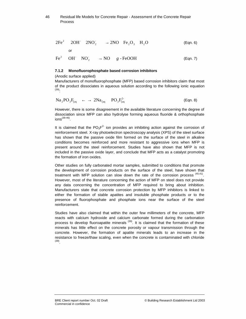
46
Residual life Models for Concrete Repair - Assessment of the Concrete Repair Process
BRE Client report number Oct. 02 Draft © Building Research Establishment Ltd 2003 Commercial in confidence
OH OFe 2NO 2NO 2OH Fe2 232-2
-2 ++→+++ (Eqn. 6)
or
FeOOH- NO NO OH Fe -2
-2 γ+→+++ (Eqn. 7)
7.1.2 Monofluorophosphate based corrosion inhibitors (Anodic surface applied) Manufacturers of monofluorophosphate (MFP) based corrosion inhibitors claim that most of the product dissociates in aqueous solution according to the following ionic equation (39):
( ) ( ) ( ) FPO 2Na FPONa -2aq3aqaq32 +→← + (Eqn. 8)
However, there is some disagreement in the available literature concerning the degree of dissociation since MFP can also hydrolyse forming aqueous fluoride & orthophosphate ions(39-46).
It is claimed that the PO3F2- ion provides an inhibiting action against the corrosion of
reinforcement steel. X-ray photoelectron spectroscopy analysis (XPS) of the steel surface has shown that the passive oxide film formed on the surface of the steel in alkaline conditions becomes reinforced and more resistant to aggressive ions when MFP is present around the steel reinforcement. Studies have also shown that MFP is not included in the passive oxide layer, and conclude that MFP acts as a catalyst promoting the formation of iron oxides.
Other studies on fully carbonated mortar samples, submitted to conditions that promote the development of corrosion products on the surface of the steel, have shown that treatment with MFP solution can slow down the rate of the corrosion process (40,41). However, most of the literature concerning the action of MFP on steel does not provide any data concerning the concentration of MFP required to bring about inhibition. Manufacturers state that concrete corrosion protection by MFP inhibitors is linked to either the formation of stable apatites and insoluble phosphate products or to the presence of fluorophosphate and phosphate ions near the surface of the steel reinforcement.
Studies have also claimed that within the outer few millimeters of the concrete, MFP reacts with calcium hydroxide and calcium carbonate formed during the carbonation process to develop fluoroapatite minerals (39). It is claimed that the formation of these minerals has little effect on the concrete porosity or vapour transmission through the concrete. However, the formation of apatite minerals leads to an increase in the resistance to freeze/thaw scaling, even when the concrete is contaminated with chloride (39).

47
Residual life Models for Concrete Repair - Assessment of the Concrete Repair Process
BRE Client report number Oct. 02 Draft © Building Research Establishment Ltd 2003 Commercial in confidence
7.1.3 Alkanolamines and amine based corrosion inhibitors (Anodic/cathodic surface applied impregnations)
Manufacturers claim that the latest liquid multi-functional concrete corrosion inhibitors provide both anodic and cathodic inhibition by adsorption at the steel/concrete interface. Such synergistic inhibitors are based on an organic and inorganic film-forming blend of amino compounds that diffuse through the concrete in both a liquid and vapour phase. The adsorbed layer formed by the corrosion inhibitor is typically in the order of 0.01µm to 0.1µm in thickness. However, since there are several propriety blends from different manufacturers it is difficult to discuss the functionality of this group of corrosion inhibitors in anything but general terms.
The use of alkanolamines and amine compounds, particularly their salts with inorganic and organic acids, as concrete corrosion inhibitors has been documented recently (47-55). Such compounds include dimethylpropanolamine, diemethylethanolamine, and diethanolamine.
The mechanism of film formation from this group of corrosion inhibitors relies on adsorption occurring at both anodic and cathodic sites on the surface of the steel. However, the published literature lacks quantitative data concerning the mechanisms of adsorption, the concentration of inhibitor adsorbed or the minimum concentration of product required to bring about an effective level of inhibition. Limited laboratory data concerning film formation on steel immersed in inhibitor containing solutions has been published (49,50). The surface analysis techniques of X-ray photon spectroscopy (XPS) and secondary ion mass spectroscopy (SIMS) have been employed to detect the presence of amino alcohols. This was then used to provide semi-quantitative information on the thickness of the adsorbed film layer.
Vapour phase inhibitors or volatile corrosion inhibitors include compounds such as dicyclohexylamine nitrite, cyclohexylamine carbonate and cyclohexylamine benzoate, contained in a pellet/tablet form. A hole is drilled into the concrete, the pellet/tablet is inserted into the hole and the hole filled with repair mortar. Mixtures of these compounds are used to produce a vapour phase inhibitor with a fast initial release and a slow vaporization into the concrete to the steel(55). Once again there is only a small proportion of quantitative data available in the published literature.
7.2 Key aspects for inhibitors
Inhibitors can be applied as concrete admixtures, surface applied or drilled in to existing structures. (Specifiers and contractors should be aware of potential patent infringement).
• Inhibitors are easily applied to most surfaces.
• The effectiveness of surface applied and vapour phased inhibitors is dependent upon reaching the steel. The permeability of the concrete is a key factor in the penetration of the inhibitor.

48
Residual life Models for Concrete Repair - Assessment of the Concrete Repair Process
BRE Client report number Oct. 02 Draft © Building Research Establishment Ltd 2003 Commercial in confidence
• There is a good track record of the effectiveness of inhibitors applied in North America.
• The concentration of chloride displaced from the surface of the steel is unclear.
• Need to establish more fully the effective distribution across the reinforcement.
• There are a number of unanswered questions regarding the use of some inhibitor types. Namely:
♦ How is the inhibitor’s progress monitored?
♦ Does corrosion remain suppressed?
♦ Is there a risk of concentrating corrosion at critical areas?
♦ How long do inhibitors work for?
♦ Do inhibitors actually reach the steel?
♦ What is their distribution on the reinforcement?
• There is confusion as to the ability of the corrosion inhibitors to arrest or reduce the corrosion rate of steel for two main reasons:
♦ It is not known how successfully the various corrosion
inhibitors migrate to the steel or in what concentrations.
♦ There is a lack of knowledge as to the concentration of
inhibitor that should be maintained at the surface of the reinforcement in
order to significantly reduce the corrosion rate of the steel, especially in
the highly variable environment of concrete.
• The various inhibitor types available have differing tolerance to maximum chloride levels in the concrete to be treated. It is recommended that manufacturers are contacted to advise on the maximum chloride levels suitable for their products.
49
Residual life Models for Concrete Repair - Assessment of the Concrete Repair Process
BRE Client report number Oct. 02 Draft © Building Research Establishment Ltd 2003 Commercial in confidence
8.0 Concrete Surface treatment
8.1 Introduction
While concrete is often considered a durable material it may in certain circumstances require protection. Following deterioration and repairs, or in the absence of sufficient cover to protect reinforcement, there is often a requirement to provide protection against penetration by water, carbon dioxide, sulphur dioxide and salts.
Protection against long-term deterioration is also a possible requirement. Additionally, there is an increasing need for decorative or colouring treatments to improve the quality of the surroundings where these contain large areas of concrete, or even for colourless waterproofing treatments to prevent accumulation of dirt and biological growths.
Three generic types of surface treatment are available for the decoration and protection of concrete surfaces, designed to control chemical ingress as well as moisture movement. They are described as follows:
• Pore-liners– these are hydrophobic impregnation treatments such as silicone impregnants, which line the pores of concrete. They repel water and therefore prevent it from entering the concrete, but continue to allow water vapour to escape.
• Pore blockers – these are materials that partially or completely block the pores in concrete. They may accomplish this by either reacting with the concrete to produce pore-blocking products or by physically blocking the pores.
• Film-formers – these are coating systems based on either organic resins such as styrene butadiene and acrylic copolymers or inorganic resins such as potassium silicate, which form a protective/decorative film on the surface of the concrete. Coatings may be endowed with special properties, such as the ability to bridge moving cracks whilst maintaining film integrity.
Film-forming coatings for concrete are principally decorative protective elastomeric products. They are formulated to form a barrier against the ingress of carbon dioxide, and other deleterious substances, yet allow the free passage of water vapour. They should exhibit a proven resistance to weathering, and maintain their elastomeric and barrier properties in service, which will often be a maintenance free life in excess of 10 years. Test certificates should be sought to demonstrate these properties.
Most surface treatment for concrete can be a combination of the types of surface treatments discussed above.

50
Residual life Models for Concrete Repair - Assessment of the Concrete Repair Process
BRE Client report number Oct. 02 Draft © Building Research Establishment Ltd 2003 Commercial in confidence
8.2 Selection process
There is no ideal set of requirements, which will lead to the selection of appropriate coating systems. Selection will involve re-iteration where possible options are reviewed against the requirements of the project. The situation in practice is more complex for the following reasons:
• The application conditions and service requirements will vary significantly from one project to another.
• The coating often has to fulfil several requirements at the same time.
• Different products may satisfy the same specification, but to different levels of effect.
• The products of the same generic type can exhibit marked variations in certain properties as a result of different formulations.
• At present there are no agreed and quantified performance criteria. European Standards for coatings on concrete will introduce quantified performance criteria, as part of the EN 1504 series.
• There is no direct relationship between test data and in-service.
Most of the European standards and classification systems for coatings on concrete, including those in the EN 1504 series, are expected to be in force presently. They will be important for the selection, specification, and testing of coatings for concrete.
prEN 1504 - 2, (Surface protection systems), gives guidance on the selection of coatings for concrete, performance requirements and the required mandatory tests for determining properties. For example, if a coating is to be used for ingress control, the manufacturer will have to test the coating for adhesion and for permeation by carbon dioxide, liquid water, and water vapour. The coating may also require testing for crack bridging ability if it is to be used on substrates where a degree of cracking is expected.
The draft standard applies to concrete surface treatments with a maximum dry film thickness of 5 mm and the different repair principles relevant to coatings are listed in Section 5.3.
The classification system from the standard, shown in Table 6, represents a significant step forward. For the first time requirements for coatings on concrete will be presented for specific use, including car parks, floors, buildings, bridges, etc.

51
Residual life Models for Concrete Repair - Assessment of the Concrete Repair Process
BRE Client report number Oct. 02 Draft © Building Research Establishment Ltd 2003 Commercial in confidence
Principles and Methods Performance characteristics
1. Ingress Protection
2. Moisture Control 5. Physical Resistance
Chemical Resistance
Increasing resistively
1.1 (H)
1.2 (l)
1.3 (C)
2.1 (H)
2.2 (C)
5.1 (C)
5.2(L)
6.1(C)
8.1 ( H)
8.2 (C)
Linear Shrinkage CIU
CIU
CIU
CIU
CIU
Compressive strength
AIU
AIU
Coefficient of thermal expansion
CIU CIU CIU CIU
CIU
Abrasion resistance
AIU AIU
Adhesion by cross-cut test
CIU
CIU CIU
CIU
CIU
Permeability to CO2 CIU AIU
Permeability to water vapour
CIU AIU AIU AIU
Capillary absorption and permeability water
AIU AIU AIU CIU AIU
Diffusion of chloride ions
CIU
CIU
CIU
Adhesion after thermal compatibility
Freeze-thaw cycling with de-icing salt impact
CIU CIU CIU CIU CIU CIU CIU
Thunder shower cycling (thermal shock)
CIU CIU CIU CIU CIU CIU CIU
Thermal cycling without de-icing salt impact
CIU CIU CIU CIU CIU CIU CIU
Resistance to thermal shock
CIU CIU CIU
Chemical resistance CIU CIU
Resistance to high chemical
AIU
Crack-bridging ability CIU
CIU CIU CIU CIU
Impact resistance
AIU AIU
Adhesion by pull-off test
CIU
AIU AIU AIU CIU AIU AIU
Fire resistance after application
CIU CIU CIU CIU CIU
Resistance against freeze-thaw salt stress of hydrophobic impreg
CIU CIU CIU
Skid resistance
CIU CIU CIU CIU CIU CIU CIU
Depth of penetration AIU AIU AIU AIU AIU
Behaviour after artification weathering
CIU CIU CIU CIU CIU
Antistatic behaviour CIU CIU CIU CIU
Physiological performance -release of dangerous substances
CIU CIU CIU CIU CIU CIU CIU CIU CIU CIU
Adhesion on wet concrete
CIU CIU CIU CIU
Water absorption and resistance alkali tests for hydrophobic impre
AIU
AIU
AIU
Drying behaviour for hydrophobic impregnation
AIU
AIU
AIU
C = Coating H = Hydrophobic impregnation L = Pore Blocker
Table 6 - prEN 1504-2 Summary of the classification system for performance testing of coatings on concrete
CIU For intended uses AIU For certain intended uses
52
Residual life Models for Concrete Repair - Assessment of the Concrete Repair Process
BRE Client report number Oct. 02 Draft © Building Research Establishment Ltd 2003 Commercial in confidence
8.3 Performance assessment of coatings
The data from testing is often included in the literature that supports and promotes individual coatings or product ranges. This can be of value to specifiers for matching particular materials to specification of standards requirements, or for comparing a range of products on offer. However impressive the data might be, the specifier should understand that it has often been obtained under laboratory conditions.
Field or site experience of product performance is extremely valuable and many manufacturers can provide case studies to support their claims. Such information can be used to advantage by the specifier/builder for formulating policy on the use of coatings. It is suggested that evidence of performance in service should take precedence over any other form of guidance or advice that is offered.
8.4 Key aspects for concrete surface treatments
• Coatings fulfil an increasing need for decorative or colouring treatments that improve the quality of the surroundings where these contain large areas of concrete, or even for colourless waterproofing treatments to prevent accumulation of dirt and biological growths.
• Surface preparation is key. Pinholes or discontinuities can degrade performance. Scrape or fairing coatings are usually required if performance is of importance.
• Coatings typically have shorter life expectancy than the structure they protect so they need to be reapplied several times during a structure’s life.
• Coatings may prevent future ingress of deleterious substances but will not, in isolation, retard existing corrosion significantly.
• There is a wide range of systems available but they should be selected to be compatible with the other concrete repair systems and techniques applied.
• High performance systems have crack bridging capabilities.
• Weathering will reduce the performance of coatings.
• Impregnants may not penetrate sufficiently into the concrete and are difficult to detect once applied.
• There may be health and safety issues during the application of certain systems.
• The performance in respect of time to first maintenance will vary depending on the
conditions and the coating system specified, but can range from only a few years to
indefinite.
• Claims made by manufacturers for product performance, especially of longevity,
should be supported by case studies.

53
Residual life Models for Concrete Repair - Assessment of the Concrete Repair Process
BRE Client report number Oct. 02 Draft © Building Research Establishment Ltd 2003 Commercial in confidence
• A full range of specifications within European Standards are being developed which
stipulate a number of key performance requirements.

54
Residual life Models for Concrete Repair - Assessment of the Concrete Repair Process
BRE Client report number Oct. 02 Draft © Building Research Establishment Ltd 2003 Commercial in confidence
9 References
1 BRE. Better building. Integrating the Supply Chain a Guide for Clients and their Consultants. BRE Digest 450, August 2000.
2 Egan, Sir John (Chairman). Rethinking Construction: The report of the Construction Industry Task
Force, London, DETR, 1998. 3 Kay, T., Assessment & Renovation of Concrete Structures, Longman Scientific & Technical, Harlow,
England, (1992), pp 25-48. 4 Schrader, E.K., Mistakes, Misconceptions, and Controversial Issues Concerning Concrete and
Concrete Repairs, Concrete International, November, (1992), p. 54-59. 5 Allen, R.T.L., Edwards, S.C. and Shaw, J.D.N. The Repair of Concrete Structures, Blackie
Academic and Professional, Glasgow, UK, (1993). 6 Perkins, P.H., Repair, Protection and Waterproofing of Concrete Structures, E&FN Spon, London,
(1997). 7 Taylor, G., Repair, Sprayed Concrete: Properties, Design and Application (Eds. Austin, S.A. and
Robins, P.J.), Whittles Publishing, Latheronwheel, UK, (1995), p 287-296. 8 King, E.S., Design for Structural Application, Sprayed Concrete: Properties, Design and Application
(Eds. Austin, S.A. and Robins, P.J.), Whittles Publishing, Latheronwheel, UK, (1995), pp 113-149. 9 EFNARC. European Specification for Sprayed Concrete, European Federation of National
Association of Specialist Repair Contractors and Material Suppliers for the Construction Industry, Aldershot, UK, (1996).
10 EFNARC. Guidelines for Specifiers and Contractors, European Federation of National Association of
Specialist Repair Contractors and Material Suppliers for the Construction Industry, Aldershot, UK, (1999).
11 AFNOR NF P 95102, Repair and Strengthening of Concrete and Masonry Constructions - Shotcrete,
French Standardisation Association (AFNOR), Paris, English translation, (1997). 12 Austin, S.A., Production and Installation, Sprayed Concrete: Properties, Design and Application
(Eds. Austin, S.A. and Robins, P.J.), Whittles Publishing, Latheronwheel, UK, (1995), pp 31-51. 13 NACE Standard RP0290-2000, Impressed current cathodic protection of reinforcing steel in
atmospherically exposed concrete structures. 14 Hondel, A.J. v.d. & Polder, R.B., Electrochemical realkalisation and chloride removal of concrete.
Construction Repair, Sept/Oct, (1992), pp 19. 15 Bennett, J.E., & Schue, T.J., Electrochemical chloride removal from concrete: A SHRP contract
report. Paper 316, Corrosion ’90, April, (1990). 16 Bennett, J.E. & Schue, T.J., Chloride Removal Implementation Guide, Strategic Highway Research
Program, Report SHRP-S-347, (1993). 17 Bennett, J.E., Fong, K.F. & Schue, T.J., ‘Electrochemical Chloride Removal and Protection of
Concrete Bridge Component: Field Trial’, Strategic Highway Research Program, Report SHRP-S-669, (1993).

55
Residual life Models for Concrete Repair - Assessment of the Concrete Repair Process
BRE Client report number Oct. 02 Draft © Building Research Establishment Ltd 2003 Commercial in confidence
18 Manning, D.G. & Pianca, F., Electrochemical removal of chloride ions from reinforced concrete; Initial evaluations of the pier S19 field trial. Technical report MAT-90-14, Ontario Ministry of Transportation.
19 Sergi, G., Page, C.L. & Thompson, D.M. Electrochemical induction of alkali silica reaction in
concrete. Materials & Structures, 24, (1991), pp 359-361. 20 Sergi, G., Walker, R.J. & Page, S.L., Mechanisms & criteria for the Realkalisation of concrete, SCI,
Corrosion of reinforcement in concrete construction, (1996). 21 Miller, J.B., Electrochemical desalination of concrete, Norwegian Concrete Technologies
Conference, (1990). 22 Miller, J.B., The treatment of carbonated concretes by electrochemical realkalisation. Norwegian
Concrete Technologies Conference, (1990). 23 Treadaway, K.W.J. & Russell, A.D., Highway and Public Works, 36, 40, September, (1968). 24 Berke, N.S., Corrosion 89, Paper 445, 10, National Association of Corrosion Engineers, Houston,
Texas, (1989). 25 Virmani, Y.P., Public Roads, 54, June, Washington DC, (1990). 26 Berke, N.S., Transportation Research Record 1211, 18, Transportation Research Board,
Washington DC, (1989). 27 Berke, N.S., Materials Performance, Oct, 41, (1989) . 28 Berke, N.S., Concrete International, July, 24, (1991). 29 Hope, B.B. & Thompson, S.V, ACI Materials Journal, Sept/Oct, 92, No 5, (1995), p 529. 30 Cigna, R., Familiari, G., Gianetti, F. & Proverbio, E., in Corrosion & Corrosion Protection of Steel in
Concrete, Ed Swamy, Sheffield Academic Press, Vol II, (1994), p 878. 31 El-Jazairi, B. & Berke, N.S., in Corrosion of Reinforcement in Concrete, Ed. Page, C.L., Treadaway,
K.W.J. & Bamforth, P.B., Elsevier, (1990). 32 Andrade, C., Alonso, C. & Gonzales, J.A., Cement, Concrete & Aggregate, CCAGDP, 8, No 2,
Winter, (1986), p 110. 33 Alonso, C. & Andrade, C., ACI Materials Journal, March/April, (1990), p 130. 34 Bongi, C., Dinghai, H., Hengguan, G. & Yinghao, Z., Cement & Concrete Research, 13, (1983), p
603. 35 Craig, R.J. & Wood, L.E., Highway Research Record, No 328, (1970), p 77. 36 Griffin, D.F., in Corrosion of Metals in Concrete, ACI SP. 49, American Concrete Institute, Detroit MI,
(1975). 37 Slater, J.E., STP818, American Society for Testing & Materials, Philadelphia PA, (1983). 38 Rosenberg, A.M. & Gaidis, J.M., Materials Performance, 18, No. 11, (1979), p 45-48. 39 Haynes, M.D. & Malric, B., Proceedings of the 7 th International Conference on Structural Faults &
Repair, 2, (1997), p 307. 40 Alonso, C., Andrade, C., Agriz, C. & Malric, B., Cement & Concrete Research, 22, (1996), p 869. 41 Andrade, C., Alonso, C., Acha, M. & Malric, B., Cement & Concrete Research, 26, (1996), p 405. 42 Annen, P. & Malric, B., in Bridge Management 3, Eds. Harding, E., Parke, A.R. & Ryall, M.J., E &
FN Spon, London, (1996).

56
Residual life Models for Concrete Repair - Assessment of the Concrete Repair Process
BRE Client report number Oct. 02 Draft © Building Research Establishment Ltd 2003 Commercial in confidence
43 Domtar, US PATENT No 5,071,579. 44 Domtar, US PATENT No 5,127,954. 45 Domtar, US PATENT No 5,314,755. 46 Raharinaivo, A., Laboratoire Central des Ponts et Chaussees, rapport DT/OAM/AR81-96. 47 Shaw, M., Proceedings of the 7 th International Conference on Structural Faults & Repair, 2, (1997),
p 317. 48 Laamanen, P.H. & Byfors, K., Nordic Concrete Research, No19/2, Norsk Betongforening, Oslo,
(1996). 49 Miksic, B.A., Tarvin, M. & Sparrow, G.R., Corrosion 89, Paper 607, 10, National Association of
Corrosion Engineers, Houston, Texas, (1989). 50 Brundle, C.R., Grunze, D., Mader, U. & Blank, N., Surf. Interface Anal., 24, (1996), p 549. 51 Bjegovic, D., Sipos, L., Ukrainczyk, V. & Miksic, B., in Corrosion & Corrosion Protection of Steel in
Concrete, Ed Swamy, Sheffield Academic Press, Vol II, (1994), p 865. 52 Maeder, U., in Corrosion & Corrosion Protection of Steel in Concrete, Ed Swamy, Sheffield
Academic Press, Vol II, (1994), p 878. 53 Concrete Bridge Protection & Rehabilitation: Chemical & Physical Techniques, SHRP-S-665,
National Research Council, Washington DC, (1993). 54 Concrete Bridge Protection & Rehabilitation: Corrosion Inhibitors & Polymers, SHRP-S-666, National
Research Council, Washington DC, (1993). 55 Miksic, B.A., Reviews on Corrosion Inhibitor Science & Technology, Eds. Raman, A. & Labine, P.,
National Association of Corrosion Engineers, Houston, Texas, (1993). 56 British Standards Institution. BS 6744:1986, Austenitic stainless steel bars for the reinforcement of
concrete, (1996). 57 Concrete Society Technical Report No. 51, Guidance on the use of stainless steel reinforcement,
(1998). 58 ASTM C876: Test method for half-cell potentials of uncoated reinforcing steel in concrete. American
National Standard. West Conshohocken, (1997).

Residual life Models for Concrete Repair - Assessment of the Concrete Repair Process
BRE Client report number © Building Research Establishment Ltd 2003 Commercial in confidence
Appendix A - Tables 1A & 2A

Residual life Models for Concrete Repair - Assessment of the Concrete Repair Process
BRE Client report number © Building Research Establishment Ltd 2003 Commercial in confidence
Appendix B - Simplified Procurement Routes for Concrete Repair

Residual life Models for Concrete Repair - Assessment of the Concrete Repair Process
BRE Client report number © Building Research Establishment Ltd 2003 Commercial in confidence
(a) Tendered - Scheduled Rates
Stage Action by Key outcomes 1(Client brief/Initiation)
Owner/Client • Decide programme & agree limitations • Assess safety implications • Set provisional budget
2(Evaluation/specification)
Consultant • Consider programme & any limitations • Technical evaluation of possible
techniques - consider options survey • Generate specification and schedule of
works 3a (Tender a)
Contractor • Review specification • Review options • (Generate own specification?)
3b (Tender b)
Specialist Contractor • Survey • Bill of Quantities
4 (Tender review)
Consultant • Check rates are realistic • Check validity of technical solution • Interview
5 (Tender acceptance)
Consultant/ Client
• Comparison to cost plan/budget
6 (Appointment)
Client/ Consultant
• Final agreement of terms & conditions
7 (work carried out)
Contractor • Repair work completed
8 (Snagging & claims?
? ?

Residual life Models for Concrete Repair - Assessment of the Concrete Repair Process
BRE Client report number © Building Research Establishment Ltd 2003 Commercial in confidence
(b) Tendered Lump Sum Stage Action by Key outcomes 1(Client brief/Initiation)
Owner/Client • Decide programme & agree limitations • Assess safety implications • Set provisional budget
2(Evaluation/specification)
Consultant • Consider programme & any limitations • Technical evaluation of possible
techniques - consider options survey • Generate specification/brief
3a (Tender a)
Contractor • Review specification • Review options • Generate own specification
3b (Tender b)
Specialist Contractor • Survey • Bill of Quantities • Price
4 (Tender review)
Consultant • Compare bid options • Check validity of technical solution • Interview
5 (Tender acceptance)
Consultant/ Client
• Comparison to cost plan/budget
6 (Appointment)
Client/ Consultant
• Final agreement of terms & conditions
7 (work carried out)
Contractor • Repair work completed
8 (Snagging & claims?
? ?

Residual life Models for Concrete Repair - Assessment of the Concrete Repair Process
BRE Client report number © Building Research Establishment Ltd 2003 Commercial in confidence
(c) Partnering Stage Action by Key outcomes 1(Client brief/Initiation)
Owner/Client • Decide programme & agree limitations • Assess safety implications • Set provisional budget
2(Evaluation/specification)
Contractor/ Specialist Contractor
• Consider programme & any limitations • Technical evaluation of possible
techniques - carry out options survey • Generate specification/brief • Price
3 (Proposal acceptance)
Client • Comparison to cost plan/budget
4 (Appointment)
Client/ Consultant
• Final agreement of terms & conditions
5 (work carried out)
Contractor • Repair work completed
6 (benefits sharing)
Contractor/Client • Review of project and agreed sharing of benefits/problems
(d) Design & Build Stage Action by Key outcomes 1(Client brief/Initiation)
Owner/Client • Decide programme & agree limitations in relation to other ongoing refurbishments
• Assess safety implications • Set provisional budget • Issue Client's requirements
documentation (performance specification and or schedule of rates)
2(Evaluation/specification)
Contractor/ Specialist Contractor
• Consider programme & any limitations • Technical evaluation of possible
techniques - consider options survey • Generate repair design • Price
3 (Proposal acceptance)
Client • Comparison to cost plan/budget
4 (Appointment)
Client/ Consultant
• Final agreement of terms & conditions
4 (work carried out)
Contractor • Repair work completed

![DRAFT ASSESSMENT REPORT APPLICATION … December 2007 [8-07] DRAFT ASSESSMENT REPORT APPLICATION A577 CALCIUM IN CHEWING GUM CONTAINING NO MORE THAN 0.2% RESIDUAL SUGARS DEADLINE FOR](https://img.dokumen.tips/doc/110x75/5af336a37f8b9a8b4c912ebb/draft-assessment-report-application-december-2007-8-07-draft-assessment-report.jpg)