Embed Size (px)
Citation preview
1
Dr INDIRA M.S.Prof and head Dept of EEE
Sir MVITSubject: Basic Electrical Sciences
Chapter Domestic Wiring
DOMESTIC WIRING
In this chapter you gain to understand the following:
Electrical domestic wiringTypes of wiring
Suitability of a particular wiring system for a given installationCorridor and staircase lightingNecessity of earthing
Different types of earthingFuses
Different types of fusesWorking of a fluorescent lamp and sodium vapor lamp
IntroductionA network of wires drawn connecting the meter board to the various energyconsuming loads (lamps, fans, motors etc) through control and protective devicesfor efficient distribution of power is known as electrical wiring.Electrical wiring done in residential and commercial buildings to provide powerfor lights, fans, pumps and other domestic appliances is known as domesticwiring. There are several wiring systems in practice. They can be classified into:
Tree system - In this system branches are tapped from the main circuit atrequired points. This involves many joints making the location of the faultpoint difficult.Though the method is economical it is visually unappealing with scatteredfuses and is affected by large voltage drops.
Distribution system - This system is more organized in the sense that themain circuit is drawn to several distribution centers and connected to thedistribution boards. Branches are tapped from these distribution boards.This system of wiring has an aesthetic appeal, as they are without jointsand also makes the location of the fault point easier. All the points aremaintained almost at the same potential. Each circuit is provided with anindependent fuse. Provides flexibility for repair and maintenance. Thissystem is widely preferred for indoor wiring though expensive.
Types of Wiring:
Cleat wiring CTS wiring or TRS wiring or batten wiring Metal sheathed wiring or lead sheathed wiring
2
Casing and capping Conduit wiring
1. Cleat wiring:
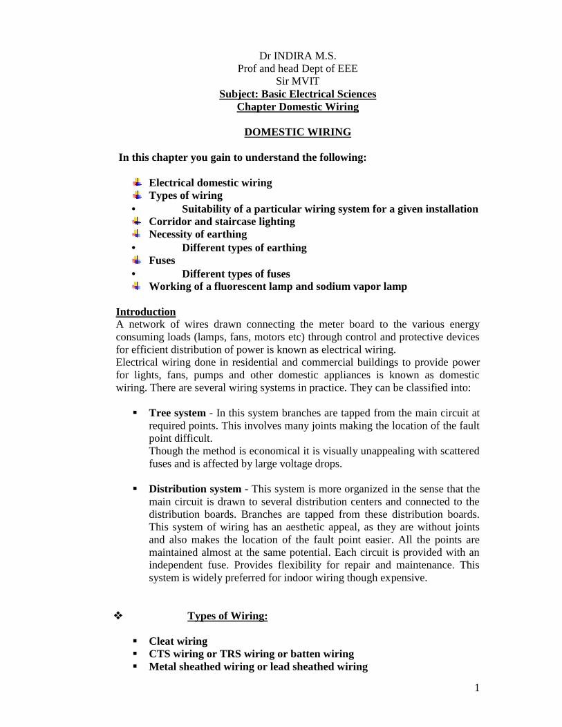
In this type of wiring, insulated conductors (usually VIR, Vulcanized IndianRubber) are supported on porcelain or wooden cleats. The cleats have two halvesone base and the other cap. The cables are placed in the grooves provided in thebase and then the cap is placed. Both are fixed securely on the walls by 40mmlong screws. The cleats are easy to erect and are fixed 4.5 – 15 cms apart. Thiswiring is suitable for temporary installations where cost is the main criteria butnot the appearance.
Advantages:
1. Easy installation2. Materials can be retrieved for reuse3. Flexibility provided for inspection, modifications and expansion.4. Relatively economical5. Skilled manpower not required.
Disadvantages:
1. Appearance is not good2. Open system of wiring requiring regular cleaning.3. Higher risk of mechanical injury.
2. CTS ( Cable Tyre Sheathed) / TRS ( Tough Rubber Sheathed )/ Batten wiring:
3
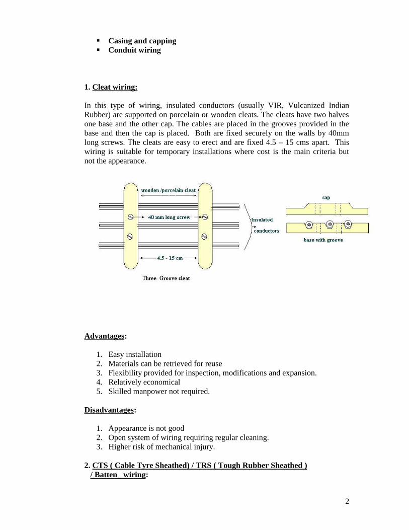
In this wiring system, wires sheathed in tough rubber are used which are quiteflexible. They are clipped on wooden battens with brass clips (link or joint) andfixed on to the walls or ceilings by flat head screws. These cables are moistureand chemical proof. They are suitable for damp climate but not suitable foroutdoor use in sunlight. TRS wiring is suitable for lighting in low voltageinstallations
Advantages:1. Easy installation and is durable2. Lower risk of short circuit.3. Cheaper than casing and capping system of wiring4. Gives a good appearance if properly erected.
Disadvantages:1. Danger of mechanical injury.2. Danger of fire hazard.3. Should not be exposed to direct sunlight.4. Skilled workmen are required.
3. Metal Sheathed or Lead Sheathed wiring :
The wiring is similar to that of CTS but the conductors (two or three) areindividually insulated and covered with a common outer lead-aluminum alloysheath. The sheath protects the cable against dampness, atmospheric extremitiesand mechanical damages. The sheath is earthed at every junction to provide a pathto ground for the leakage current. They are fixed by means of metal clips onwooden battens. The wiring system is very expensive. It is suitable for lowvoltage installations.
Precautions to be taken during installation1. The clips used to fix the cables on battens should not react with the sheath.2. Lead sheath should be properly earthed to prevent shocks due to leakage
currents.3. Cables should not be run in damp places and in areas where chemicals
(may react with the lead) are used.
Advantages:1. Easy installation and is aesthetic in appearance.
4
2. Highly durable3. Suitable in adverse climatic conditions provided the joints are not exposed
Disadvantages:1. Requires skilled labor2. Very expensive3. Unsuitable for chemical industries
4. Casing and Capping:
It consists of insulated conductors laid inside rectangular, teakwood or PVC boxeshaving grooves inside it. A rectangular strip of wood called capping having samewidth as that of casing is fixed over it. Both the casing and the capping arescrewed together at every 15 cms. Casing is attached to the wall. Two or morewires of same polarity are drawn through different grooves. The system is suitablefor indoor and domestic installations.
Advantages:1. Cheaper than lead sheathed and conduit wiring.2. Provides good isolation as the conductors are placed apart reducing the
risk of short circuit.3. Easily accessible for inspection and repairs.4. Since the wires are not exposed to atmosphere, insulation is less affected
by dust, dirt and climatic variations.
Disadvantages:1. Highly inflammable.2. Usage of unseasoned wood gets damaged by termites.3. Skilled workmanship required.
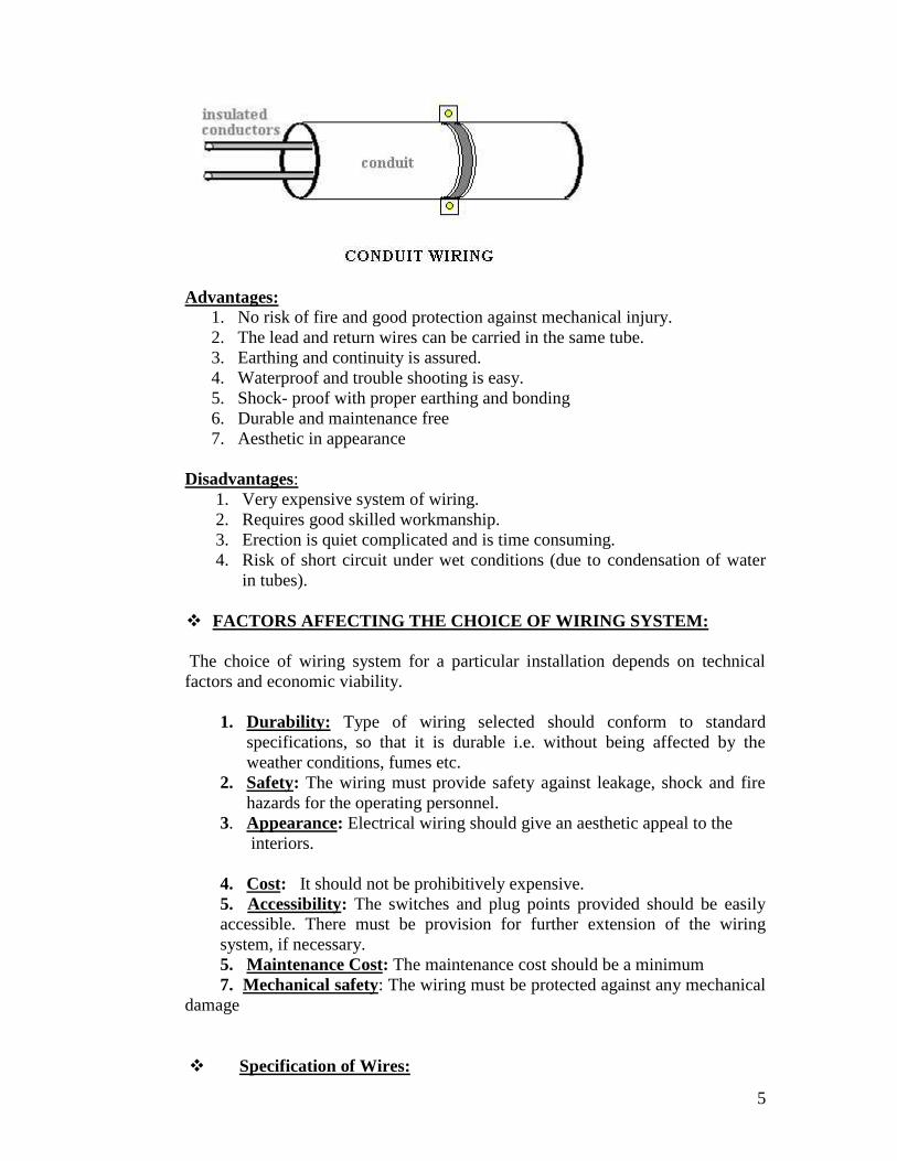
5. Conduit wiring:
In this system PVC (polyvinyl chloride) or VIR cables are run through metallicor PVC pipes providing good protection against mechanical injury and fire due toshort circuit. They are either embedded inside the walls or supported over thewalls, and are known as concealed wiring or surface conduit wiring (openconduit) respectively. The conduits are buried inside the walls on wooden guttiesand the wires are drawn through them with fish (steel) wires. The system is bestsuited for public buildings, industries and workshops.
5
Advantages:1. No risk of fire and good protection against mechanical injury.2. The lead and return wires can be carried in the same tube.3. Earthing and continuity is assured.4. Waterproof and trouble shooting is easy.5. Shock- proof with proper earthing and bonding6. Durable and maintenance free7. Aesthetic in appearance
Disadvantages:1. Very expensive system of wiring.2. Requires good skilled workmanship.3. Erection is quiet complicated and is time consuming.4. Risk of short circuit under wet conditions (due to condensation of water
in tubes).
FACTORS AFFECTING THE CHOICE OF WIRING SYSTEM:
The choice of wiring system for a particular installation depends on technicalfactors and economic viability.
1. Durability: Type of wiring selected should conform to standardspecifications, so that it is durable i.e. without being affected by theweather conditions, fumes etc.
2. Safety: The wiring must provide safety against leakage, shock and firehazards for the operating personnel.
3. Appearance: Electrical wiring should give an aesthetic appeal to theinteriors.
4. Cost: It should not be prohibitively expensive.5. Accessibility: The switches and plug points provided should be easilyaccessible. There must be provision for further extension of the wiringsystem, if necessary.5. Maintenance Cost: The maintenance cost should be a minimum7. Mechanical safety: The wiring must be protected against any mechanical
damage
Specification of Wires:
6
The conductor material, insulation, size and the number of cores, specifies theelectrical wires. These are important parameters as they determine the current andvoltage handling capability of the wires. The conductors are usually of eithercopper or aluminum. Various insulating materials like PVC, TRS, and VIR areused. The wires may be of single strand or multi strand. Wires with combinationof different diameters and the number of cores or strands are available.For example: The VIR conductors are specified as 1/20, 3/22,….7/20 ………The numerator indicates the number of strands while the denominator
corresponds to the diameter of the wire in SWG (Standard Wire Gauge). SWG 20corresponds to a wire of diameter 0.914mm, while SWG 22 corresponds to a wireof diameter 0.737 mm.A 7/0 wire means, it is a 7-cored wire of diameter 12.7mm (0.5 inch). The
selection of the wire is made depending on the requirement considering factorslike current and voltage ratings, cost and application.Example: Application: domestic wiring
1. Lighting - 3/20 copper wire2. Heating - 7/20 copper wire
The enamel coating (on the individual strands) mutually insulates the strands andthe wire on the whole is provided with PVC insulation. The current carryingcapacity depends on the total area of the wire. If cost is the criteria thenaluminum conductors are preferred. In that case, for the same current ratingmuch larger diameter of wire is to be used.
Two- way and Three- way Control of Lamps:
The domestic lighting circuits are quite simple and they are usually controlledfrom one point. But in certain cases it might be necessary to control a single lampfrom more than one point (Two or Three different points).For example: staircases, long corridors, large halls etc.
Two-way Control of lamp:
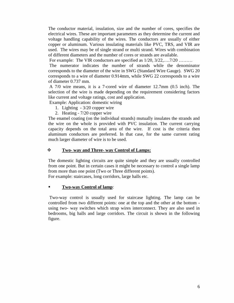
Two-way control is usually used for staircase lighting. The lamp can becontrolled from two different points: one at the top and the other at the bottom -using two- way switches which strap wires interconnect. They are also used inbedrooms, big halls and large corridors. The circuit is shown in the followingfigure.
7
Switches S1 and S2 are two-way switches with a pair of terminals 1&2, and 3&4respectively. When the switch S1 is in position1 and switch S2 is in position 4, thecircuit does not form a closed loop and there is no path for the current to flow andhence the lamp will be OFF. When S1 is changed to position 2 the circuit getscompleted and hence the lamp glows or is ON. Now if S2 is changed to position 3with S1 at position 2 the circuit continuity is broken and the lamp is off. Thus thelamp can be controlled from two different points.
Position of S1 Position of S2 Condition of lamp1 3 ON1 4 OFF2 3 OFF2 4 ON
Sonic.ico
Animation Instruction: The lamp to be made ON or OFF depending onthe position of the switches S1 and S2. and the corresponding entry in thetable to be highlighted along with the flow of current in the circuit. Currentto flow when the circuit is complete and no flow of current indicated whenthe circuit is incomplete.
Three- way Control of lamp:
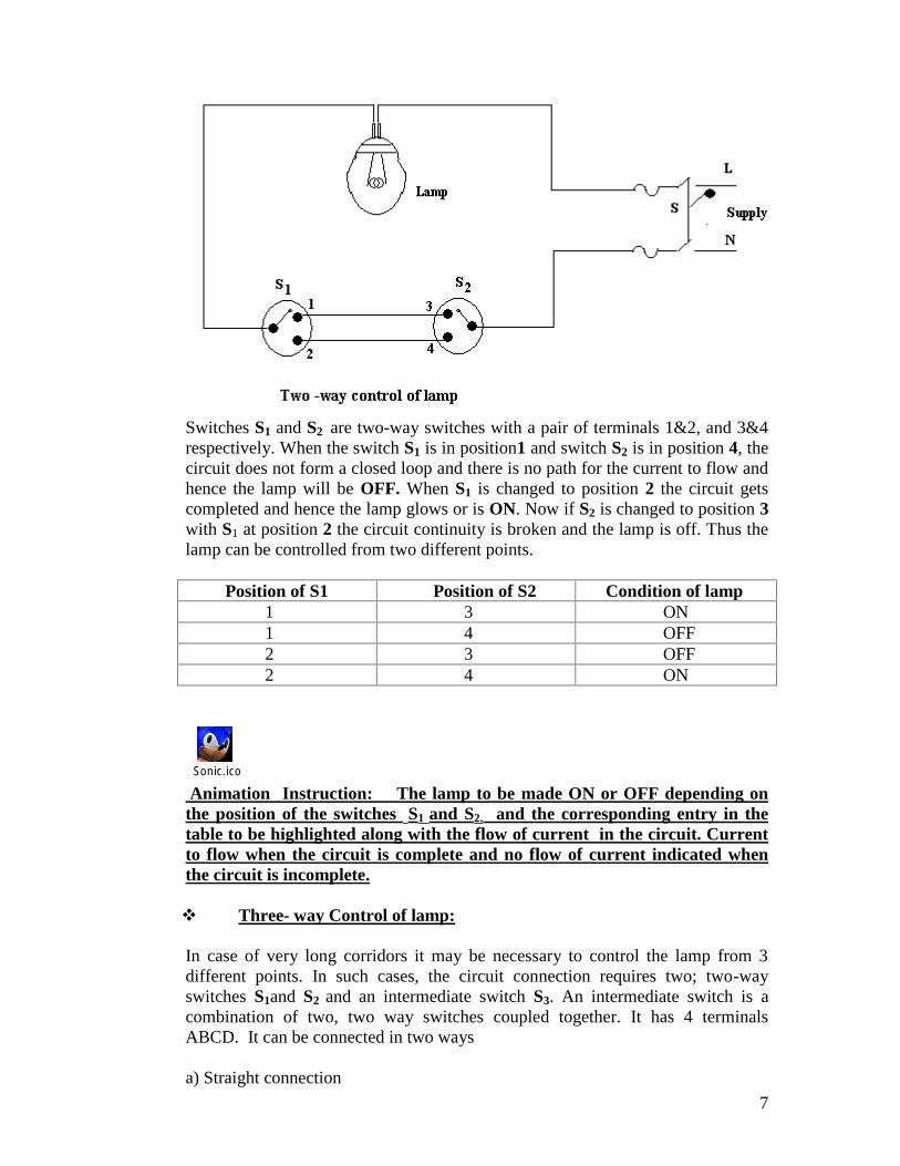
In case of very long corridors it may be necessary to control the lamp from 3different points. In such cases, the circuit connection requires two; two-wayswitches S1and S2 and an intermediate switch S3. An intermediate switch is acombination of two, two way switches coupled together. It has 4 terminalsABCD. It can be connected in two ways
a) Straight connection
8
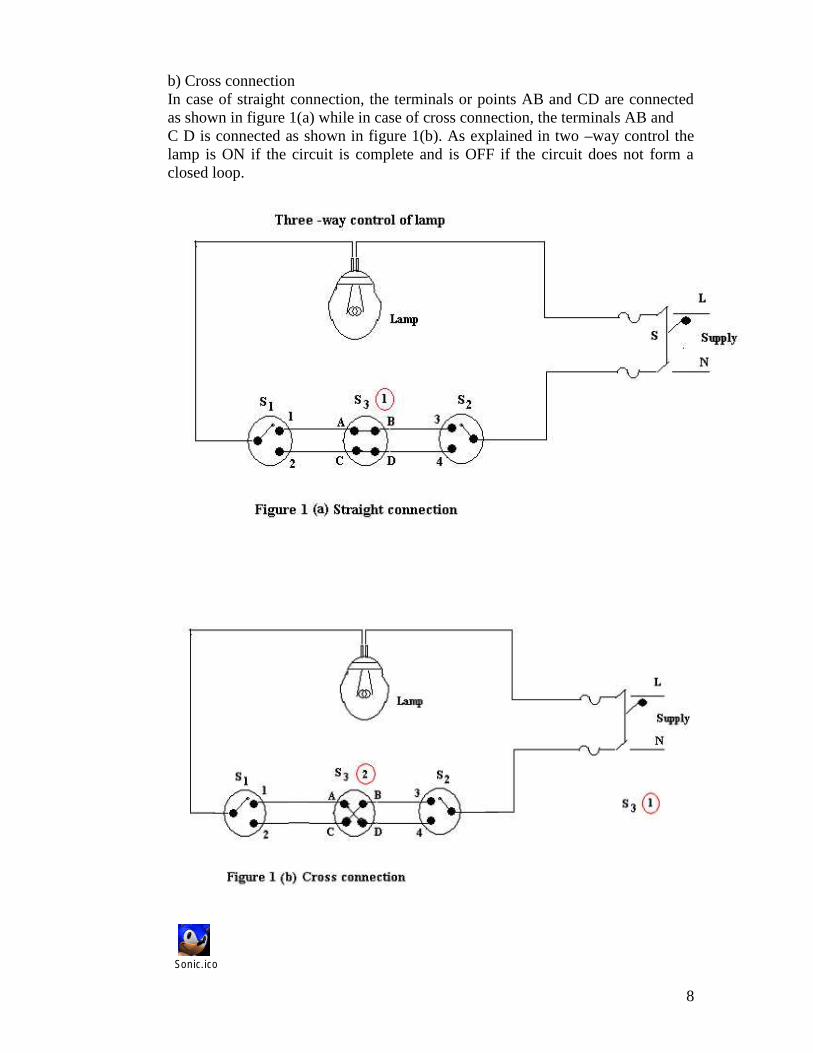
b) Cross connectionIn case of straight connection, the terminals or points AB and CD are connectedas shown in figure 1(a) while in case of cross connection, the terminals AB andC D is connected as shown in figure 1(b). As explained in two –way control thelamp is ON if the circuit is complete and is OFF if the circuit does not form aclosed loop.
Sonic.ico
9
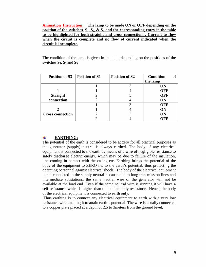
Animation Instruction: The lamp to be made ON or OFF depending on theposition of the switches S1 S2. & S3 and the corresponding entry in the tableto be highlighted for both straight and cross connection. . Current to flowwhen the circuit is complete and no flow of current indicated when thecircuit is incomplete.
The condition of the lamp is given in the table depending on the positions of theswitches S1, S2 and S3.
Position of S3 Position of S1 Position of S2 Condition ofthe lamp
1Straight
connection
1122
3434
ONOFFOFFON
2Cross connection
1122
3434
OFFONONOFF
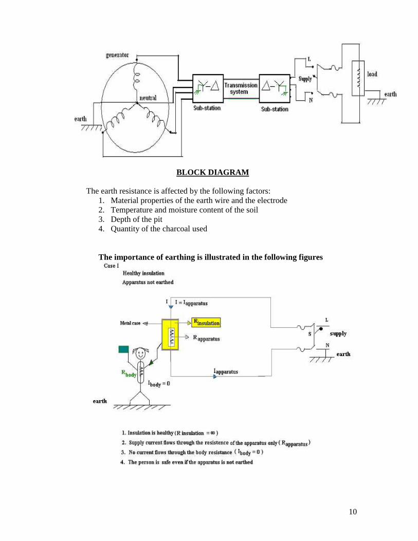
EARTHING:The potential of the earth is considered to be at zero for all practical purposes asthe generator (supply) neutral is always earthed. The body of any electricalequipment is connected to the earth by means of a wire of negligible resistance tosafely discharge electric energy, which may be due to failure of the insulation,line coming in contact with the casing etc. Earthing brings the potential of thebody of the equipment to ZERO i.e. to the earth’s potential, thus protecting theoperating personnel against electrical shock. The body of the electrical equipmentis not connected to the supply neutral because due to long transmission lines andintermediate substations, the same neutral wire of the generator will not beavailable at the load end. Even if the same neutral wire is running it will have aself-resistance, which is higher than the human body resistance. Hence, the bodyof the electrical equipment is connected to earth only.Thus earthing is to connect any electrical equipment to earth with a very low
resistance wire, making it to attain earth’s potential. The wire is usually connectedto a copper plate placed at a depth of 2.5 to 3meters from the ground level.
10
BLOCK DIAGRAM
The earth resistance is affected by the following factors:1. Material properties of the earth wire and the electrode2. Temperature and moisture content of the soil3. Depth of the pit4. Quantity of the charcoal used
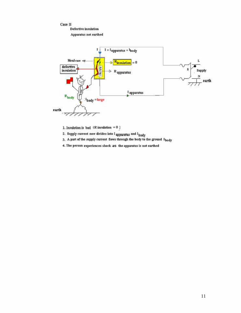
The importance of earthing is illustrated in the following figures
11
12
Sonic.ico
Animation Instruction: When the supply switch S is closed in Case I currentflows only through the healthy apparatus. No current flows through theperson and does not experience a shock.
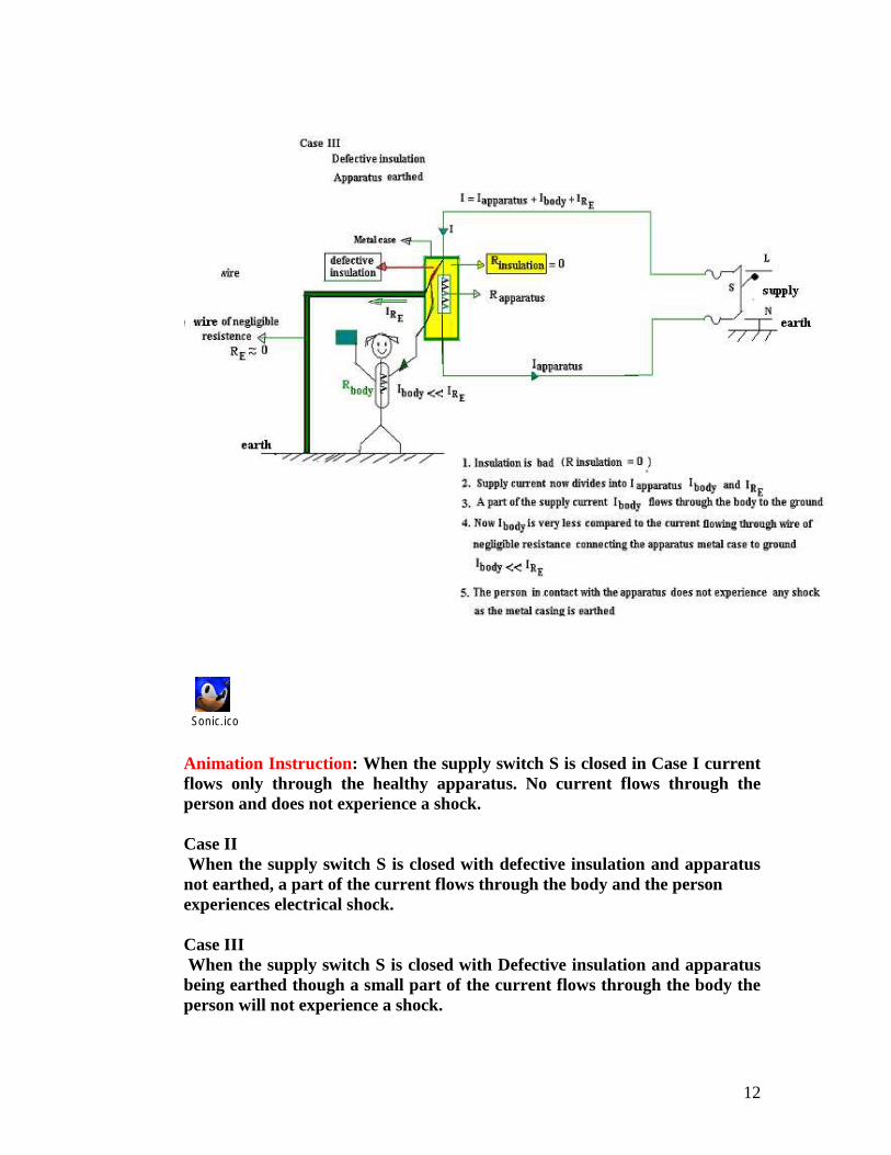
Case IIWhen the supply switch S is closed with defective insulation and apparatus
not earthed, a part of the current flows through the body and the personexperiences electrical shock.
Case IIIWhen the supply switch S is closed with Defective insulation and apparatus
being earthed though a small part of the current flows through the body theperson will not experience a shock.
13
Necessity of Earthing:1. To protect the operating personnel from danger of shock in case they
come in contact with the charged frame due to defective insulation.2. To maintain the line voltage constant under unbalanced load condition.3. Protection of the equipments4. Protection of large buildings and all machines fed from overhead lines
against lightning.
Methods of Earthing:The important methods of earthing are the plate earthing and the pipe earthing.The earth resistance for copper wire is 1 ohm and that of G I wire less than 3ohms. The earth resistance should be kept as low as possible so that the neutral ofany electrical system, which is earthed, is maintained almost at the earthpotential. The typical value of the earth resistance at powerhouse is 0. 5 ohm andthat at substation is 1 ohm.
1. Plate earthing2. Pipe earthing
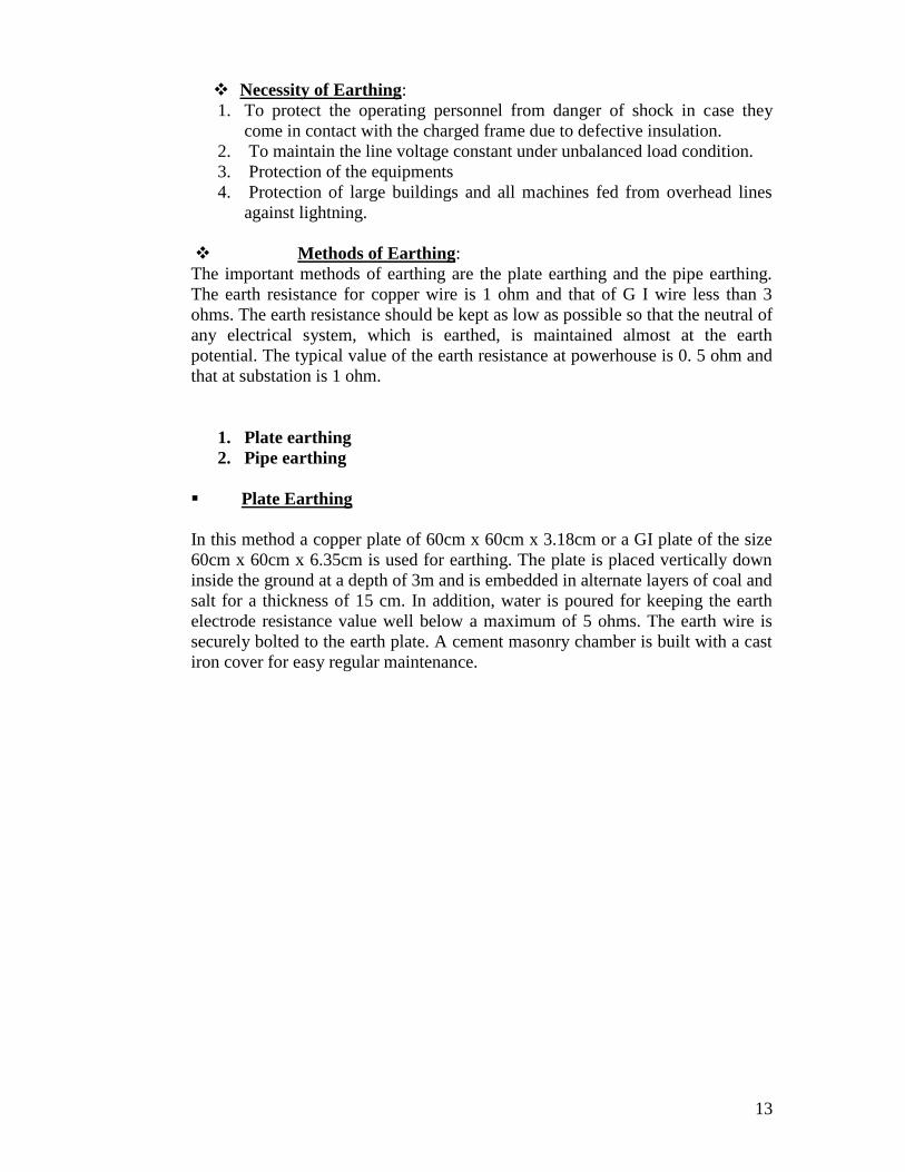
Plate Earthing
In this method a copper plate of 60cm x 60cm x 3.18cm or a GI plate of the size60cm x 60cm x 6.35cm is used for earthing. The plate is placed vertically downinside the ground at a depth of 3m and is embedded in alternate layers of coal andsalt for a thickness of 15 cm. In addition, water is poured for keeping the earthelectrode resistance value well below a maximum of 5 ohms. The earth wire issecurely bolted to the earth plate. A cement masonry chamber is built with a castiron cover for easy regular maintenance.
14
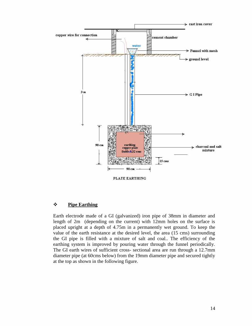
Pipe Earthing
Earth electrode made of a GI (galvanized) iron pipe of 38mm in diameter andlength of 2m (depending on the current) with 12mm holes on the surface isplaced upright at a depth of 4.75m in a permanently wet ground. To keep thevalue of the earth resistance at the desired level, the area (15 cms) surroundingthe GI pipe is filled with a mixture of salt and coal.. The efficiency of theearthing system is improved by pouring water through the funnel periodically.The GI earth wires of sufficient cross- sectional area are run through a 12.7mmdiameter pipe (at 60cms below) from the 19mm diameter pipe and secured tightlyat the top as shown in the following figure.
15
When compared to the plate earth system the pipe earth system can carry largerleakage currents as a much larger surface area is in contact with the soil for agiven electrode size. The system also enables easy maintenance as the earth wireconnection is housed at the ground level.
PROTECTIVE DEVICES
Protection for electrical installation must be provided in the event of faultssuch as short circuit, overload and earth faults. The protective circuit ordevice must be fast acting and isolate the faulty part of the circuitimmediately. It also helps in isolating only required part of the circuit withoutaffecting the remaining circuit during maintenance. The following devices areusually used to provide the necessary protection:
Fuses Relays Miniature circuit breakers (MCB) Earth leakage circuit breakers (ELCB)
16
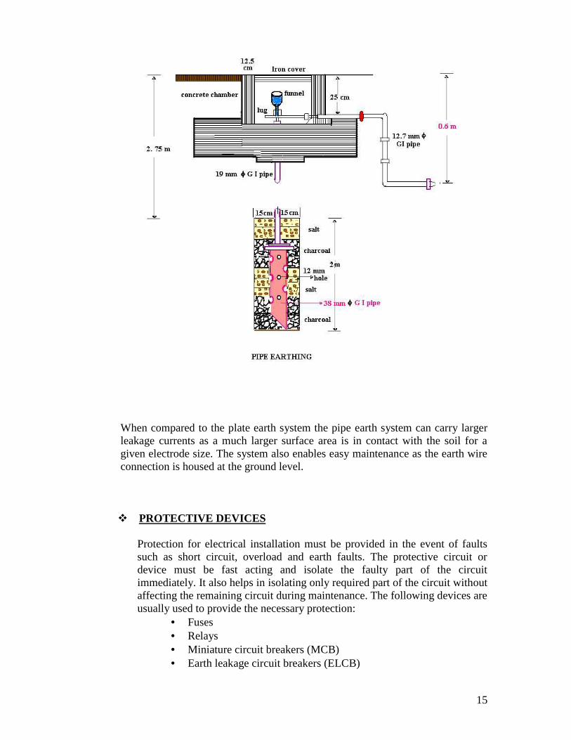
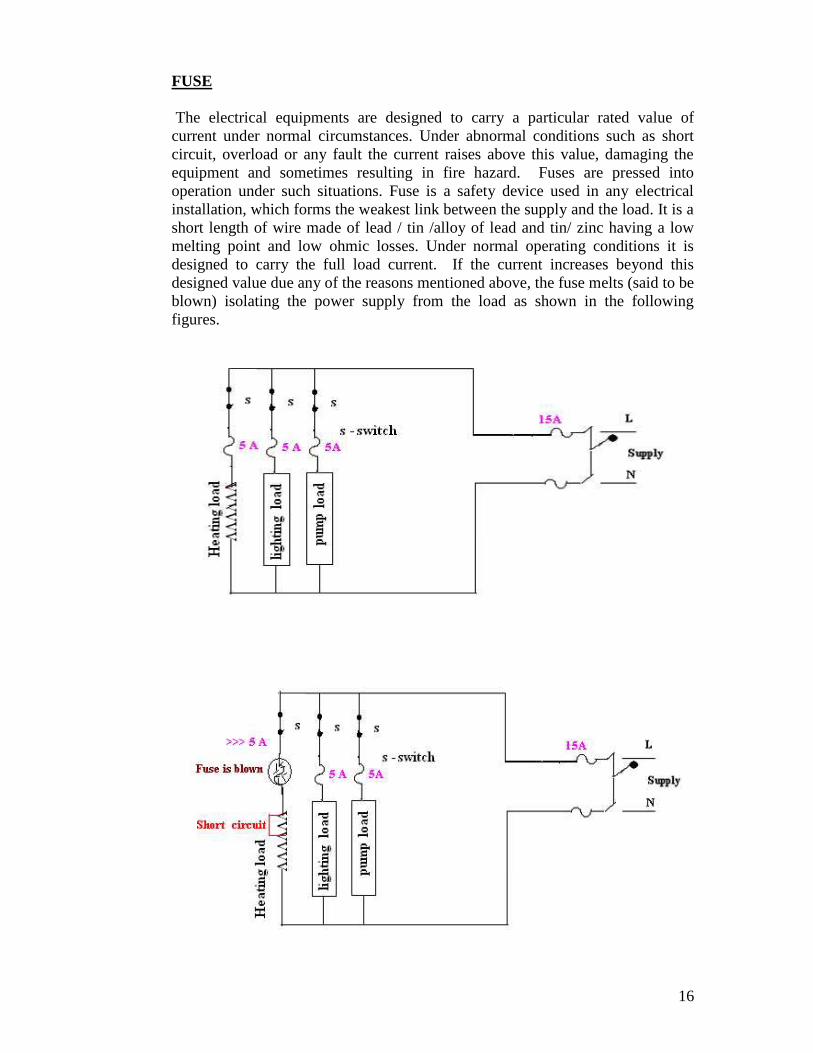
FUSE
The electrical equipments are designed to carry a particular rated value ofcurrent under normal circumstances. Under abnormal conditions such as shortcircuit, overload or any fault the current raises above this value, damaging theequipment and sometimes resulting in fire hazard. Fuses are pressed intooperation under such situations. Fuse is a safety device used in any electricalinstallation, which forms the weakest link between the supply and the load. It is ashort length of wire made of lead / tin /alloy of lead and tin/ zinc having a lowmelting point and low ohmic losses. Under normal operating conditions it isdesigned to carry the full load current. If the current increases beyond thisdesigned value due any of the reasons mentioned above, the fuse melts (said to beblown) isolating the power supply from the load as shown in the followingfigures.
17
CHARACTERISTICS OF FUSE MATERIAL
The material used for fuse wires must have the following characteristics1. Low melting point2. Low ohmic losses3. High conductivity4. Lower rate of deterioration
Different types of fuses:
Re-wirable or kit -kat fuses: These fuses are simple in construction,cheap and available up-to a current rating of 200A. They are erratic inoperation and their performance deteriorates with time.
Plug fuse: The fuse carrier is provided with a glass window for visualinspection of the fuse wire.
Cartridge fuse: Fuse wire usually an alloy of lead is enclosed in a strongfiber casing. The fuse element is fastened to copper caps at the ends of thecasing. They are available up-to a voltage rating of 25kV. They are usedfor protection in lighting installations and power lines.
Miniature Cartridge fuses: These are the miniature version of the higherrating cartridge fuses, which are extensively used in automobiles, TV sets,and other electronic equipments.
Transformer fuse blocks: These porcelain housed fuses are placed onsecondary of the distribution transformers for protection against shortcircuits and overloads.
Expulsion fuses: These consist of fuse wire placed in hollow tube of fiberlined with asbestos. These are suited only for out door use for example,protection of high voltage circuits.
Semi-enclosed re-wirable fuses: These have limited use because of lowbreaking capacity.
Time-delay fuse: These are specially designed to withstand a currentoverload for a limited time and find application in motor circuits.
HRC CARTRIDGE FUSE
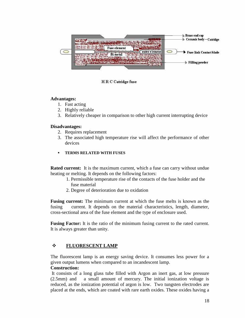
The high rupturing capacity or (HRC) fuse consists of a heat resistant ceramicbody. Then silver or bimetallic fuse element is welded to the end brass caps. Thespace surrounding the fuse element is filled with quartz powder. This fillermaterial absorbs the arc energy and extinguishes it.When the current exceeds the rated value the element melts and vaporizes. Thevaporized silver fuses with the quartz and offers a high resistance and the arc isextinguished.
18
Advantages:1. Fast acting2. Highly reliable3. Relatively cheaper in comparison to other high current interrupting device
Disadvantages:2. Requires replacement3. The associated high temperature rise will affect the performance of other
devices
TERMS RELATED WITH FUSES
Rated current: It is the maximum current, which a fuse can carry without undueheating or melting. It depends on the following factors:
1. Permissible temperature rise of the contacts of the fuse holder and thefuse material
2. Degree of deterioration due to oxidation
Fusing current: The minimum current at which the fuse melts is known as thefusing current. It depends on the material characteristics, length, diameter,cross-sectional area of the fuse element and the type of enclosure used.
Fusing Factor: It is the ratio of the minimum fusing current to the rated current.It is always greater than unity.
FLUORESCENT LAMP
The fluorescent lamp is an energy saving device. It consumes less power for agiven output lumens when compared to an incandescent lamp.Construction:It consists of a long glass tube filled with Argon an inert gas, at low pressure
(2.5mm) and a small amount of mercury. The initial ionization voltage isreduced, as the ionization potential of argon is low. Two tungsten electrodes areplaced at the ends, which are coated with rare earth oxides. These oxides having a
19
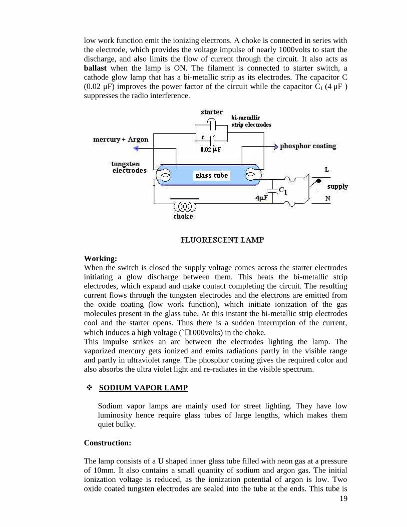
low work function emit the ionizing electrons. A choke is connected in series withthe electrode, which provides the voltage impulse of nearly 1000volts to start thedischarge, and also limits the flow of current through the circuit. It also acts asballast when the lamp is ON. The filament is connected to starter switch, acathode glow lamp that has a bi-metallic strip as its electrodes. The capacitor C(0.02 μF) improves the power factor of the circuit while the capacitor C1 (4 μF )suppresses the radio interference.
Working:When the switch is closed the supply voltage comes across the starter electrodesinitiating a glow discharge between them. This heats the bi-metallic stripelectrodes, which expand and make contact completing the circuit. The resultingcurrent flows through the tungsten electrodes and the electrons are emitted fromthe oxide coating (low work function), which initiate ionization of the gasmolecules present in the glass tube. At this instant the bi-metallic strip electrodescool and the starter opens. Thus there is a sudden interruption of the current,which induces a high voltage (`1000volts) in the choke.This impulse strikes an arc between the electrodes lighting the lamp. Thevaporized mercury gets ionized and emits radiations partly in the visible rangeand partly in ultraviolet range. The phosphor coating gives the required color andalso absorbs the ultra violet light and re-radiates in the visible spectrum.
SODIUM VAPOR LAMP
Sodium vapor lamps are mainly used for street lighting. They have lowluminosity hence require glass tubes of large lengths, which makes themquiet bulky.
Construction:
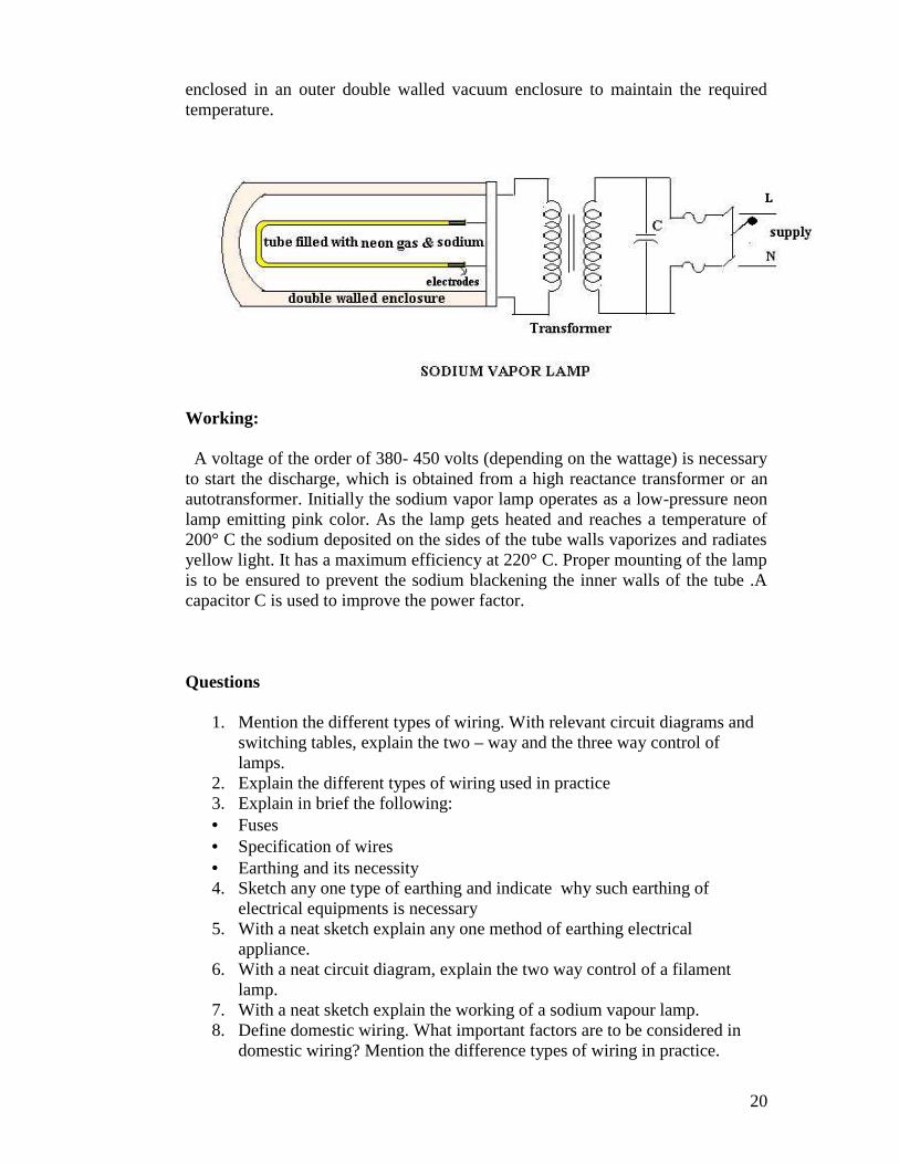
The lamp consists of a U shaped inner glass tube filled with neon gas at a pressureof 10mm. It also contains a small quantity of sodium and argon gas. The initialionization voltage is reduced, as the ionization potential of argon is low. Twooxide coated tungsten electrodes are sealed into the tube at the ends. This tube is
20
enclosed in an outer double walled vacuum enclosure to maintain the requiredtemperature.
Working:
A voltage of the order of 380- 450 volts (depending on the wattage) is necessaryto start the discharge, which is obtained from a high reactance transformer or anautotransformer. Initially the sodium vapor lamp operates as a low-pressure neonlamp emitting pink color. As the lamp gets heated and reaches a temperature of200° C the sodium deposited on the sides of the tube walls vaporizes and radiatesyellow light. It has a maximum efficiency at 220° C. Proper mounting of the lampis to be ensured to prevent the sodium blackening the inner walls of the tube .Acapacitor C is used to improve the power factor.
Questions
1. Mention the different types of wiring. With relevant circuit diagrams andswitching tables, explain the two – way and the three way control oflamps.
2. Explain the different types of wiring used in practice3. Explain in brief the following: Fuses Specification of wires Earthing and its necessity4. Sketch any one type of earthing and indicate why such earthing of
electrical equipments is necessary5. With a neat sketch explain any one method of earthing electrical
appliance.6. With a neat circuit diagram, explain the two way control of a filament
lamp.7. With a neat sketch explain the working of a sodium vapour lamp.8. Define domestic wiring. What important factors are to be considered in
domestic wiring? Mention the difference types of wiring in practice.
21
9. What do you understand by “Earthing”? With a neat diagram explain plateearthing.
10. With a neat circuit diagram and a switching table, explain the two pointcontrol of a lamp.
11. With a neat sketch explain the pipe earthing method.12. Explain the working principle of a fluorescent lamp when connected to an
electrical supply source, with necessary auxiliary components and theirfunctions
22
THREE PHASE INDUCTION MOTOR
In this chapter you will be introduced to asynchronous motors or inductionmotors.
Construction of squirrel cage and slip ring Induction motors Production of rotating flux Principle of operation Necessity of a starter for 3-phase induction motor Star –Delta starter Slip
By the end of the chapter you will be able to answer questions like: Why 3-phase induction motor cannot run with zero slip? Why 1-phase induction is motors not self starting? Why induction motors are the most preferred ac motors for many
industrial applications? What do you understand by revolving flux?
INTRODUCTION
The asynchronous motors or the induction motors are most widely used ac motorsin industry. They convert electrical energy in AC form into mechanical energy.They work on the principle of electromagnetic induction. They are simple andrugged in construction, quite economical with good operating characteristics andefficiency, requiring minimum maintenance, but have a low starting torque. Theyrun at practically constant speed from no load to full load condition. The 3 -phase induction motors are self starting while the single phase motors are not selfstarting as they produce equal and opposite torques (zero resultant torque) makingthe rotor stationary. The speed of the squirrel cage induction motor cannot bevaried easily.
CLASSIFICATION -
They are basically classified into two types based on the rotor construction1. Squirrel cage motor2. Slip ring motor or phase wound motor
CONSTRUCTION
Three phase induction motor consists of two parts(1) stator (2) rotor
Stator
It is the stationary part of the motor supporting the entire motor assembly. Thisouter frame is made up of a single piece of cast iron in case of small machines. In
23
case of larger machines they are fabricated in sections of steel and bolted together.The core is made of thin laminations of silicon steel and flash enameled to reduceeddy current and hysteresis losses. Slots are evenly spaced on the inner peripheryof the laminations. Conductors insulated from each other are placed in these slotsand are connected to form a balanced 3 - phase star or delta connected statorcircuit. Depending on the desired speed the stator winding is wound for therequired number of poles. Greater the speed lesser is the number of poles.
Rotor
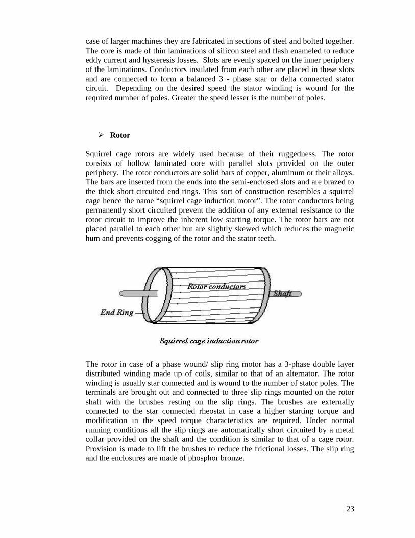
Squirrel cage rotors are widely used because of their ruggedness. The rotorconsists of hollow laminated core with parallel slots provided on the outerperiphery. The rotor conductors are solid bars of copper, aluminum or their alloys.The bars are inserted from the ends into the semi-enclosed slots and are brazed tothe thick short circuited end rings. This sort of construction resembles a squirrelcage hence the name “squirrel cage induction motor”. The rotor conductors beingpermanently short circuited prevent the addition of any external resistance to therotor circuit to improve the inherent low starting torque. The rotor bars are notplaced parallel to each other but are slightly skewed which reduces the magnetichum and prevents cogging of the rotor and the stator teeth.
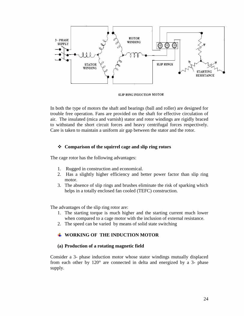
The rotor in case of a phase wound/ slip ring motor has a 3-phase double layerdistributed winding made up of coils, similar to that of an alternator. The rotorwinding is usually star connected and is wound to the number of stator poles. Theterminals are brought out and connected to three slip rings mounted on the rotorshaft with the brushes resting on the slip rings. The brushes are externallyconnected to the star connected rheostat in case a higher starting torque andmodification in the speed torque characteristics are required. Under normalrunning conditions all the slip rings are automatically short circuited by a metalcollar provided on the shaft and the condition is similar to that of a cage rotor.Provision is made to lift the brushes to reduce the frictional losses. The slip ringand the enclosures are made of phosphor bronze.
24
In both the type of motors the shaft and bearings (ball and roller) are designed fortrouble free operation. Fans are provided on the shaft for effective circulation ofair. The insulated (mica and varnish) stator and rotor windings are rigidly bracedto withstand the short circuit forces and heavy centrifugal forces respectively.Care is taken to maintain a uniform air gap between the stator and the rotor.
Comparison of the squirrel cage and slip ring rotors
The cage rotor has the following advantages:
1. Rugged in construction and economical.2. Has a slightly higher efficiency and better power factor than slip ring
motor.3. The absence of slip rings and brushes eliminate the risk of sparking which
helps in a totally enclosed fan cooled (TEFC) construction.
The advantages of the slip ring rotor are:1. The starting torque is much higher and the starting current much lower
when compared to a cage motor with the inclusion of external resistance.2. The speed can be varied by means of solid state switching
WORKING OF THE INDUCTION MOTOR
(a) Production of a rotating magnetic field
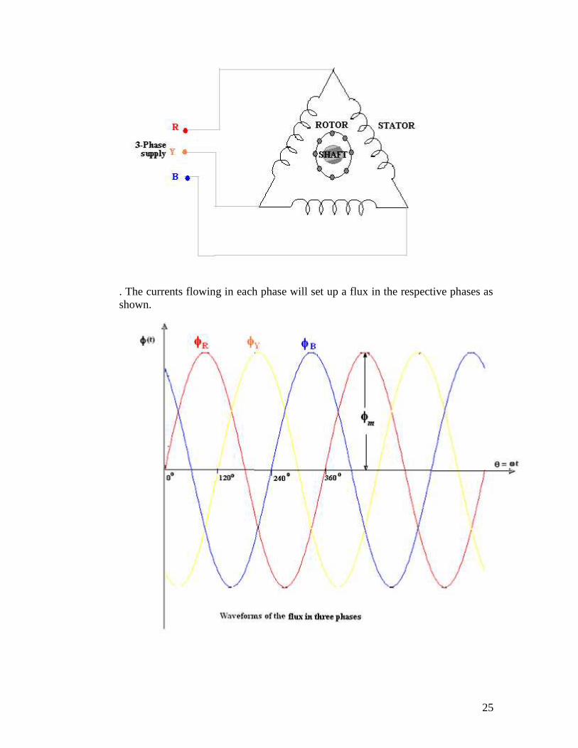
Consider a 3- phase induction motor whose stator windings mutually displacedfrom each other by 120° are connected in delta and energized by a 3- phasesupply.
25
. The currents flowing in each phase will set up a flux in the respective phases asshown.
26
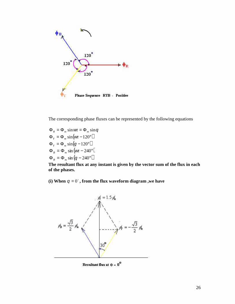
The corresponding phase fluxes can be represented by the following equations
120sin
120sin
sinsin
mY
mY
mmR
t
t
240sin
240sin
mB
mB t
The resultant flux at any instant is given by the vector sum of the flux in eachof the phases.
(i) When 0 , from the flux waveform diagram ,we have
27
mm
mmB
mkmY
R
The
5..1)30cos(2
3*2
by,givenisfluxresultant
2
3)240sin(
2
3)120sin(
0
r
r
mB 2
3
mY 2
3
m 5.1r
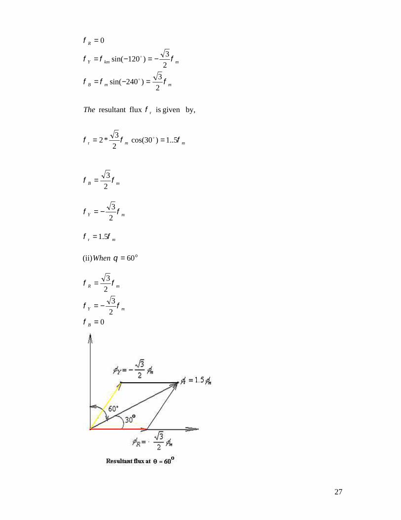
(ii) o60When
02
3
2
3
B
mY
mR
28
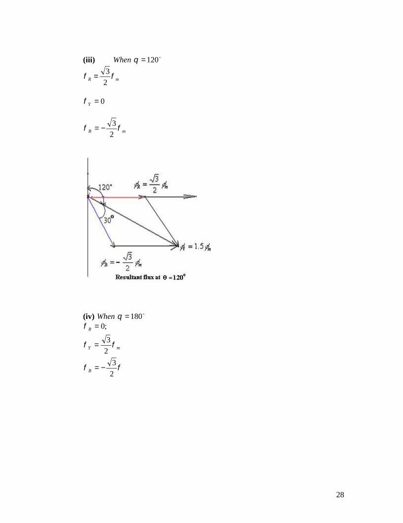
(iii) 012When
mR 2
3
0Y
mB 2
3
(iv) 180When
2
3
2
3
;0
B
mY
R
29
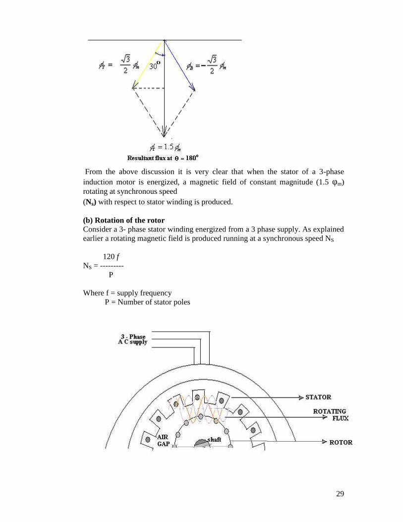
From the above discussion it is very clear that when the stator of a 3-phaseinduction motor is energized, a magnetic field of constant magnitude (1.5 φm)rotating at synchronous speed(Ns) with respect to stator winding is produced.
(b) Rotation of the rotorConsider a 3- phase stator winding energized from a 3 phase supply. As explainedearlier a rotating magnetic field is produced running at a synchronous speed NS
120 fNS = ---------
P
Where f = supply frequencyP = Number of stator poles
30
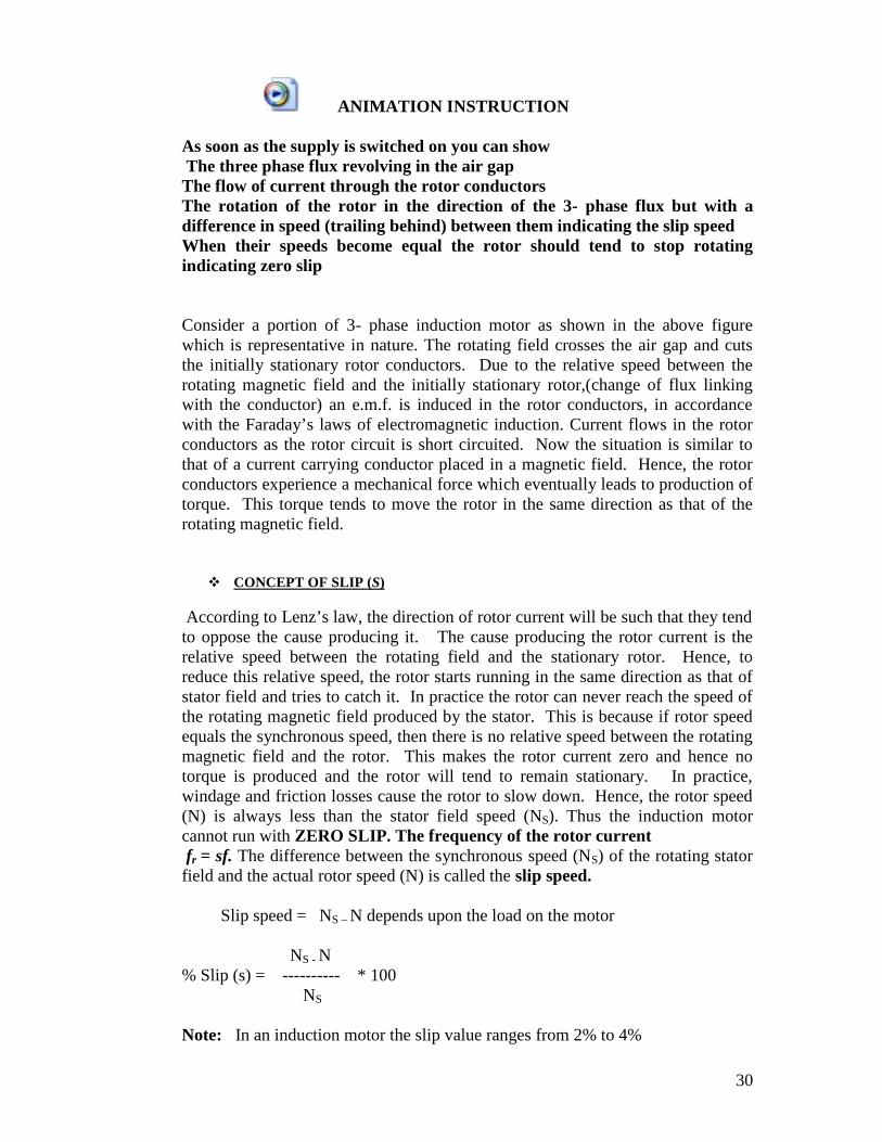
ANIMATION INSTRUCTION
As soon as the supply is switched on you can showThe three phase flux revolving in the air gap
The flow of current through the rotor conductorsThe rotation of the rotor in the direction of the 3- phase flux but with adifference in speed (trailing behind) between them indicating the slip speedWhen their speeds become equal the rotor should tend to stop rotatingindicating zero slip
Consider a portion of 3- phase induction motor as shown in the above figurewhich is representative in nature. The rotating field crosses the air gap and cutsthe initially stationary rotor conductors. Due to the relative speed between therotating magnetic field and the initially stationary rotor,(change of flux linkingwith the conductor) an e.m.f. is induced in the rotor conductors, in accordancewith the Faraday’s laws of electromagnetic induction. Current flows in the rotorconductors as the rotor circuit is short circuited. Now the situation is similar tothat of a current carrying conductor placed in a magnetic field. Hence, the rotorconductors experience a mechanical force which eventually leads to production oftorque. This torque tends to move the rotor in the same direction as that of therotating magnetic field.
CONCEPT OF SLIP (S)
According to Lenz’s law, the direction of rotor current will be such that they tendto oppose the cause producing it. The cause producing the rotor current is therelative speed between the rotating field and the stationary rotor. Hence, toreduce this relative speed, the rotor starts running in the same direction as that ofstator field and tries to catch it. In practice the rotor can never reach the speed ofthe rotating magnetic field produced by the stator. This is because if rotor speedequals the synchronous speed, then there is no relative speed between the rotatingmagnetic field and the rotor. This makes the rotor current zero and hence notorque is produced and the rotor will tend to remain stationary. In practice,windage and friction losses cause the rotor to slow down. Hence, the rotor speed(N) is always less than the stator field speed (NS). Thus the induction motorcannot run with ZERO SLIP. The frequency of the rotor currentfr = sf. The difference between the synchronous speed (NS) of the rotating stator
field and the actual rotor speed (N) is called the slip speed.
Slip speed = NS – N depends upon the load on the motor
NS - N% Slip (s) = ---------- * 100
NS
Note: In an induction motor the slip value ranges from 2% to 4%
31
APPLICATIONS OF INDUCTION MOTORS
Squirrel cage induction motor
Squirrel cage induction motors are simple and rugged in construction, arerelatively cheap and require little maintenance. Hence, squirrel cage inductionmotors are preferred in most of the industrial applications such as in
i) Lathesii) Drilling machinesiii) Agricultural and industrial pumpsiv) Industrial drives.
Slip ring induction motors
Slip ring induction motors when compared to squirrel cage motors have highstarting torque, smooth acceleration under heavy loads, adjustable speed and goodrunning characteristics.
They are used in
i) Liftsii) Cranesiii) Conveyors , etc.,
Necessity of starters for 3 phase induction motor
When a 3- phase motor of higher rating is switched on directly from the mains itdraws a starting current of about 4 -7 times the full load (depending upon on thedesign) current. This will cause a drop in the voltage affecting the performance ofother loads connected to the mains. Hence starters are used to limit the initialcurrent drawn by the 3 phase induction motors.The starting current is limited by applying reduced voltage in case of squirrel cagetype induction motor and by increasing the impedance of the motor circuit in caseof slip ring type induction motor. This can be achieved by the following methods.
1. Star –delta starter2. Auto transformer starter3. Soft starter
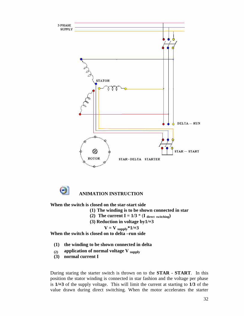
Star delta starter
The star delta starter is used for squirrel cage induction motor whose statorwinding is delta connected during normal running conditions. The two ends ofeach phase of the stator winding are drawn out and connected to the starterterminals as shown in the following figure.
32
ANIMATION INSTRUCTION
When the switch is closed on the star-start side(1) The winding is to be shown connected in star(2) The current I = 1/3 * (I direct switching)(3) Reduction in voltage by1/3
V = V supply*1/3When the switch is closed on to delta –run side
(1) the winding to be shown connected in delta
(2) application of normal voltage V supply(3) normal current I
During staring the starter switch is thrown on to the STAR - START. In thisposition the stator winding is connected in star fashion and the voltage per phaseis 1/3 of the supply voltage. This will limit the current at starting to 1/3 of thevalue drawn during direct switching. When the motor accelerates the starter
33
switch is thrown on to the DELTA - RUN side. In this position the statorwinding gets connected in the fashion and the motor draws the normal ratedcurrent.
WORKED EXAMPLES
1. A 12 pole, 3 phase alternator is coupled to an engine running at 500 rpm. Itsupplies an Induction Motor which ahs a full load speed of 1440 rpm. Find thepercentage slop and the number of poles of the motor.
Solution: NA = synchronous speed of the alternator
PNA 12 X 500F =------- = --------------- = 50 Hz (from alternator data)
120 120
When the supply frequency is 50 Hz, the synchronous speed can be 750 rpm,1500 rpm, 3000rpm etc., since the actual speed is 1440 rpm and the slip is alwaysless than 5% the synchronous speed of the Induction motor is 1500 rpm.
NS – N 1500 - 1440s = --------- = ----------------- = 0.04 OR 4%
NS 1500
120f 120 x 50NS = ------------ = -------------- = 1500
P P P = 4
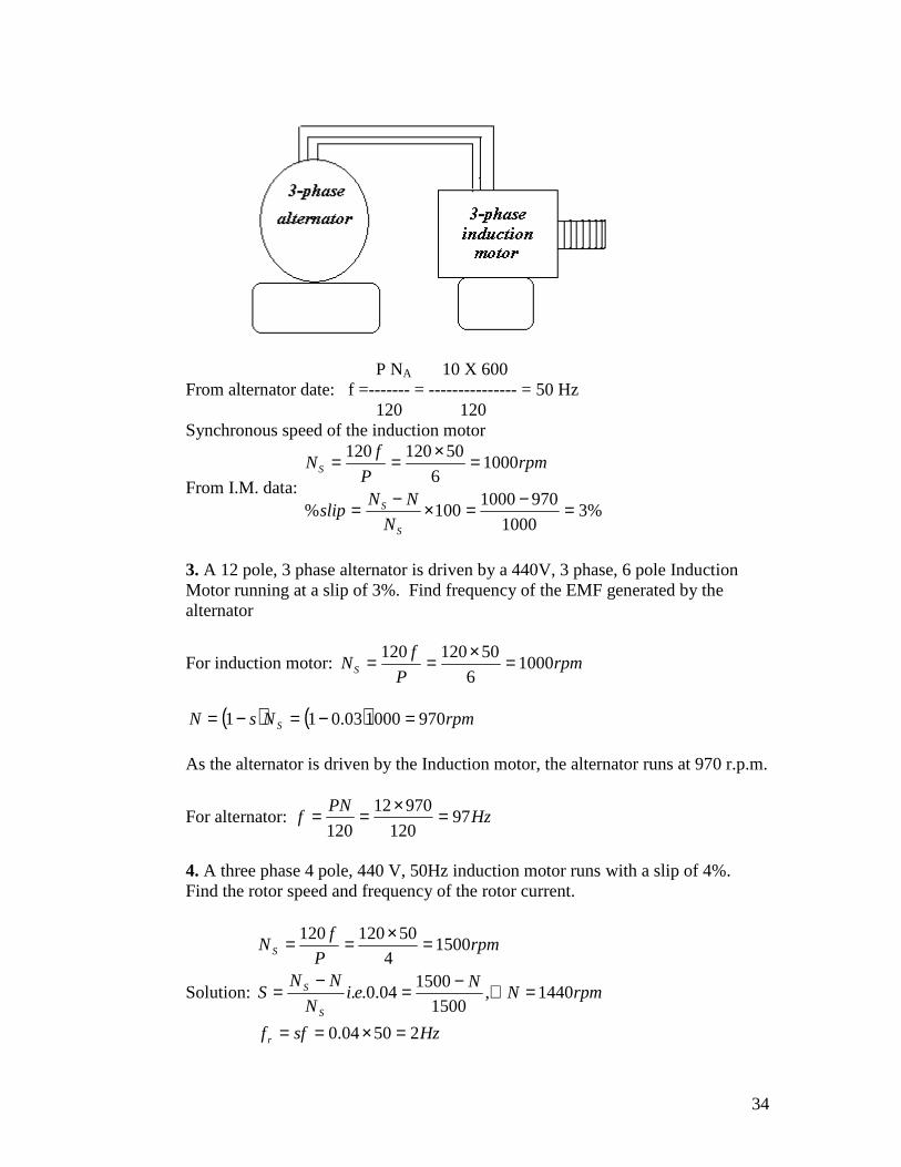
2. A 6 pole induction motor is supplied by a 10 pole alternator, which is driven at600 rpm. If the induction motor is running at 970 rpm, determine its percentageslip.
34
P NA 10 X 600From alternator date: f =------- = --------------- = 50 Hz
120 120Synchronous speed of the induction motor
From I.M. data:%3
1000
9701000100%
10006
50120120
S
S
S
N
NNslip
rpmP
fN
3. A 12 pole, 3 phase alternator is driven by a 440V, 3 phase, 6 pole InductionMotor running at a slip of 3%. Find frequency of the EMF generated by thealternator
For induction motor: rpmP
fNS 1000
6
50120120
rpmNsN S 970100003.011
As the alternator is driven by the Induction motor, the alternator runs at 970 r.p.m.
For alternator: HzPN
f 97120
97012
120
4. A three phase 4 pole, 440 V, 50Hz induction motor runs with a slip of 4%.Find the rotor speed and frequency of the rotor current.
Solution:
Hzsff
rpmNN
eiN
NNS
rpmP
fN
r
S
S
S
25004.0
1440,1500
150004.0..
15004
50120120
35
5. A 3 phase, 50Hz 6 pole induction motor has a full load percentage slip of 3%.Find(i) Synchronous speed and (ii) Actual Speed
Solution:rpmN
Nei
N
NNS
rpmP
fN
S
S
S
9701000
10003.0..
10006
50120120
6. A 3 phase induction motor has 6 poles and runs at 960 RPM on full load. It issupplied from an alternator having 4 poles and running at 1500 RPM. Calculatethe full load slip and the frequency of the rotor currents of the induction motor.
Solution:
Hzsfr
N
NNS
rpmP
fN
motoronforInducti
dataalternatorfromHzPN
f
S
S
S
25004.0f
4%or04.01000
9601000
10006
50120120
)(50120
15004
120
7. The frequency of the e.m.f in the stator of a 4-pole induction motor is 50 Hz
and that of the rotor isHz
2
11
. What is the slip and at what speed is the motor
running?Solution:Given P = 4
f = 50HzHzf r 5.1
To calculate slip (s)
We have
%3
03.050
5.1
505.1
s
s
s
S
sff r
36
ii) To calculate the speed of the motor (N)
We have
rpmN
P
fN
s
s
15004
50120
120
We also have
rpmN
N
sNN s
1455
03.011500
1
8. A 3-phase, 60Hz induction motor has a slip of 3% at full load. Find thesynchronous speed, the full- load speed and the frequency of rotor current at fullload.
SolutionGiven P = 6
f = 60Hzs= 3% = 0.03
To find the synchronous speed (Ns)We have
rpmNP
fN
s
s
12006
60120120
To calculate the full load speed (N)We have
rpmN
sNN s
1164
)03.01(12001
To calculate the frequency of the rotor current ( fr)We have
Hzf
sff
r
r
8.1
6003.0
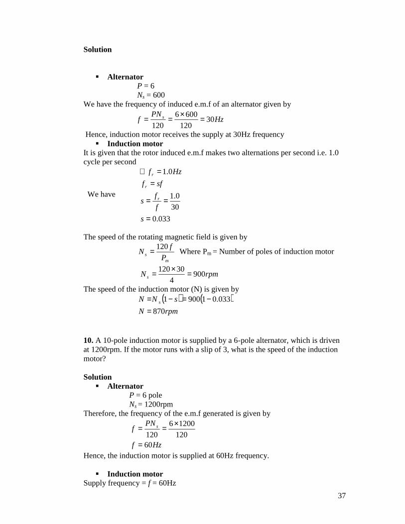
9. A 6-pole alternator running at 600 rpm. supplies a 3-phase, 4-pole inductionmotor. If the induction motor induced e.m.f makes 2 alternations per second, findthe speed of the motor.
37
Solution
AlternatorP = 6Ns = 600
We have the frequency of induced e.m.f of an alternator given by
HzPN
f s 30120
6006
120
Hence, induction motor receives the supply at 30Hz frequency Induction motor
It is given that the rotor induced e.m.f makes two alternations per second i.e. 1.0cycle per second
We have
033.0
30
0.1
0.1
s
f
fs
sff
Hzf
r
r
r
The speed of the rotating magnetic field is given by
ms P
fN
120 Where Pm = Number of poles of induction motor
rpmN s 9004
30120
The speed of the induction motor (N) is given by rpmN
sNN s
870
033.019001
10. A 10-pole induction motor is supplied by a 6-pole alternator, which is drivenat 1200rpm. If the motor runs with a slip of 3, what is the speed of the inductionmotor?
Solution Alternator
P = 6 poleNs = 1200rpm
Therefore, the frequency of the e.m.f generated is given by
Hzf
PNf s
60120
12006
120
Hence, the induction motor is supplied at 60Hz frequency.
Induction motorSupply frequency = f = 60Hz
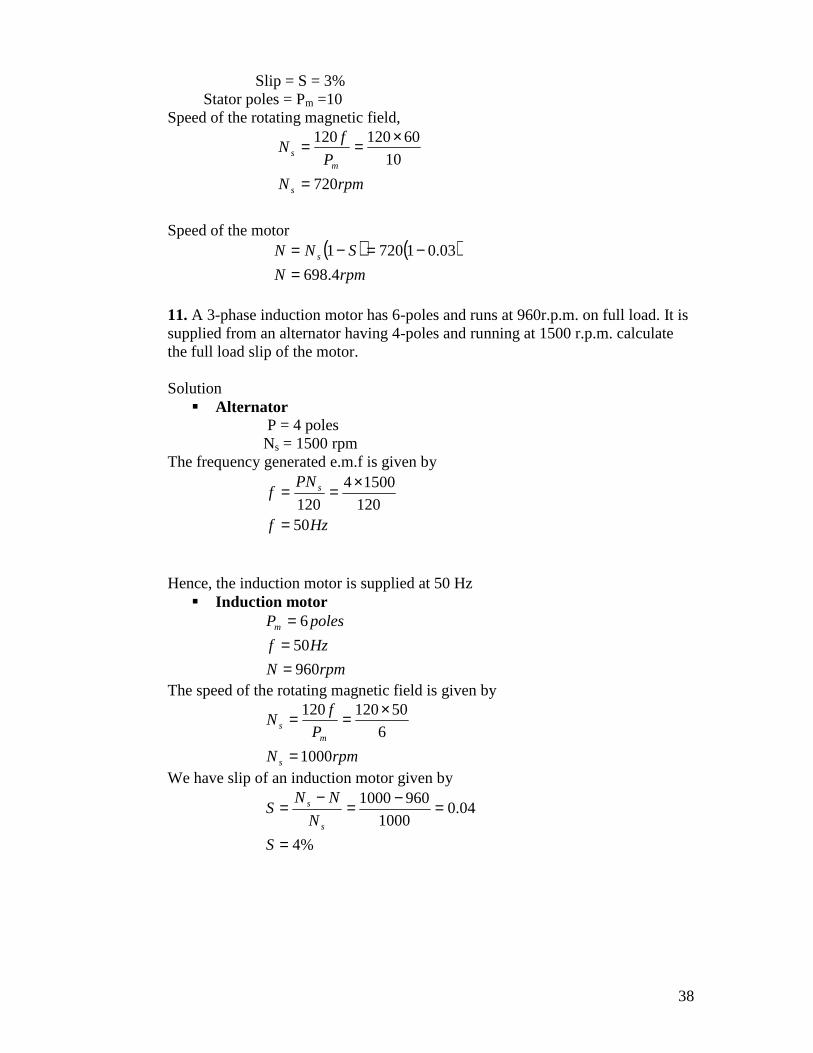
38
Slip = S = 3%Stator poles = Pm =10
Speed of the rotating magnetic field,
rpmN
P
fN
s
ms
720
10
60120120
Speed of the motor
rpmN
SNN s
4.698
03.017201
11. A 3-phase induction motor has 6-poles and runs at 960r.p.m. on full load. It issupplied from an alternator having 4-poles and running at 1500 r.p.m. calculatethe full load slip of the motor.
Solution Alternator
P = 4 polesNs = 1500 rpm
The frequency generated e.m.f is given by
Hzf
PNf s
50120
15004
120
Hence, the induction motor is supplied at 50 Hz Induction motor
rpmN
Hzf
polesPm
960
50
6
The speed of the rotating magnetic field is given by
rpmN
P
fN
s
ms
1000
6
50120120
We have slip of an induction motor given by
%4
04.01000
9601000
S
N
NNS
s
s
39
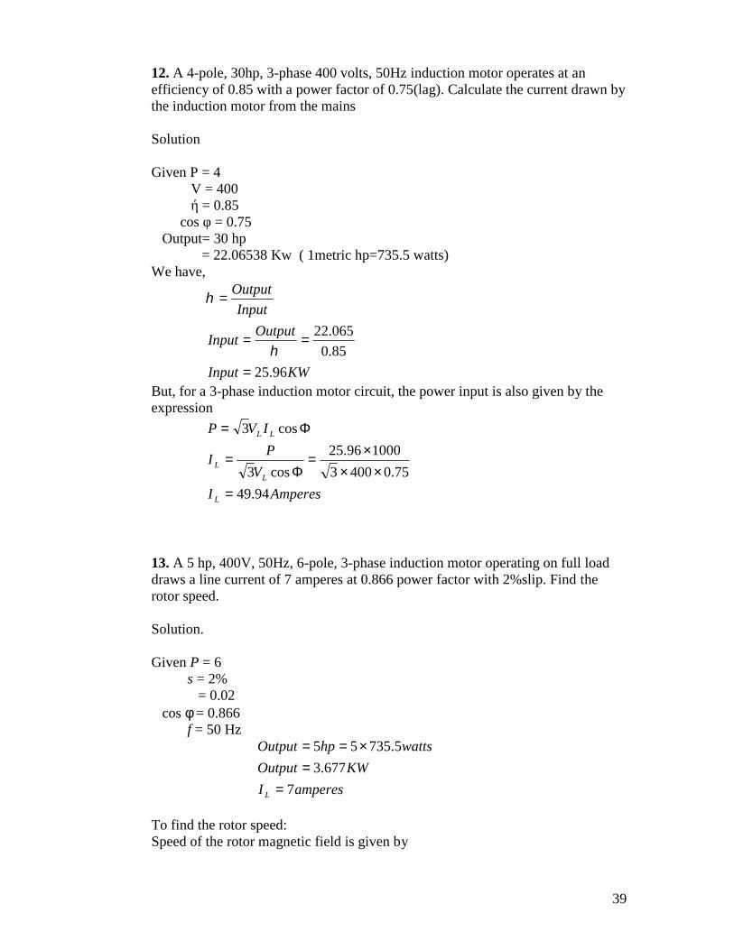
12. A 4-pole, 30hp, 3-phase 400 volts, 50Hz induction motor operates at anefficiency of 0.85 with a power factor of 0.75(lag). Calculate the current drawn bythe induction motor from the mains
Solution
Given P = 4V = 400ή = 0.85
cos φ = 0.75Output= 30 hp
= 22.06538 Kw ( 1metric hp=735.5 watts)We have,
KWInput
OutputInput
Input
Output
96.25
85.0
065.22
But, for a 3-phase induction motor circuit, the power input is also given by theexpression
AmperesI
V
PI
IVP
L
L
L
LL
94.49
75.04003
100096.25
cos3
cos3
13. A 5 hp, 400V, 50Hz, 6-pole, 3-phase induction motor operating on full loaddraws a line current of 7 amperes at 0.866 power factor with 2%slip. Find therotor speed.
Solution.
Given P = 6s = 2%
= 0.02cos = 0.866
f = 50 Hz
amperesI
KWOutput
wattshpOutput
L 7
677.3
5.73555
To find the rotor speed:Speed of the rotor magnetic field is given by

40
rpmNP
fN
s
s
10006
50120120
Speed of the rotor = N =Ns (1-s)= 1000(1-0.02)
N = 980rpm
14. A 3-phase, 6-pole, 50 Hz induction motor has a slip of 1% at no-load and3%at full-load. Find:
1. Synchronous speed,2. No-load speed3. Full-load speed,4. Frequency of rotor current at standstill, and5. Frequency of rotor current at full-load
Solution. Number of poles, p = 6No- load slip, s0 = 1%Full-load slip, sf = 3%
1. Synchronous speed,
).(..100060
50120120Ansmpr
p
fN s
2. No-load speed N0 ,
We know that
).(..990100
111001
1
00 AnsmprsNN
sNorNN
NNs
s
ss
s
3. Full – load speed
).(..970100
3110001 AnsmprsNN fsf
4. Frequency of rotor current at standstill, fr
At standstill,
).(50501
1
AnsHzsff
s
r
5. Frequency of rotor current at full – load, fr =?
).(5.150100
3AnsHzfsf r
41
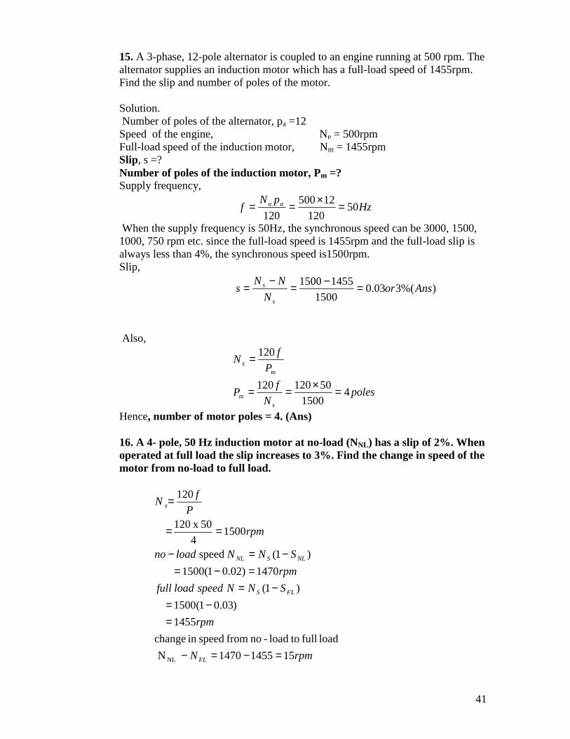
15. A 3-phase, 12-pole alternator is coupled to an engine running at 500 rpm. Thealternator supplies an induction motor which has a full-load speed of 1455rpm.Find the slip and number of poles of the motor.
Solution.Number of poles of the alternator, pa =12
Speed of the engine, Ne = 500rpmFull-load speed of the induction motor, Nm = 1455rpmSlip, s =?Number of poles of the induction motor, Pm =?Supply frequency,
HzpN
f aa 50120
12500
120
When the supply frequency is 50Hz, the synchronous speed can be 3000, 1500,1000, 750 rpm etc. since the full-load speed is 1455rpm and the full-load slip isalways less than 4%, the synchronous speed is1500rpm.Slip,
)%(303.01500
14551500Ansor
N
NNs
s
s
Also,
polesN
fP
P
fN
sm
ms
41500
50120120
120
Hence, number of motor poles = 4. (Ans)
16. A 4- pole, 50 Hz induction motor at no-load (NNL) has a slip of 2%. Whenoperated at full load the slip increases to 3%. Find the change in speed of themotor from no-load to full load.
rpmN
rpm
SNNspeedloadfull
rpm
SNNloadno
rpm
P
fN
FL
FLS
NLSNL
s
1514551470N
loadfull toload-nofromspeedinchange
1455
)03.01(1500
)1(
1470)02.01(1500
)1(speed
15004
50 x120
120
NL
42
ANSWER THE FOLLOWING QUESTIONS
(1)What do you mean by rotating magnetic field and explain the productionof torque in a three phase induction motor?(2) A three phase, 50 Hz 6 pole induction motor has a full load percentageslip o 3%.Find the synchronous speed and the actual speed.(3) Explain how torque is produced in a 3-phase induction motor?(4) Why a 3-phase induction motor cannot run with zero slip?(5) What do you understand by slip?(6)Why is a single phase induction motor not self starting?(7)Why starters are necessary for starting a 3-phase induction motor?(8)Explain with a neat diagram the working of a STAR-DELTA starter?(9)Bring out the differences between a squirrel cage and a slip ring inductionmotor.(10)Why is squirrel cage induction motor widely used for industrialapplications?(11) Mention the applications of squirrel cage and slip ring induction motors.
43
Notes by V.Muralidhar BIT, Bangalore
D.C. MACHINES.Working principle of D.C.Machine as generator and motor,constructional features, EMF equation of generator and simpleproblems, back emf and torque equation of DC motors, simpleproblems, types of DC motors, characteristics and applications,necessity of starter, 3-point starter.______________________________________________________________________A machine which works on direct current is defined as a D.C.Machine.
D.C.Machines are of two types. (i) D.C.Generator and (ii) D.C.Motor.
Sl.No. D.C. Generator D.C.Motor1 Definition:
A generator is a rotatingmachine which convertsmechanical energy intoelectrical energy
Definition:A motor is a machine whichconverts electrical energy intomechanical energy
2 Principle:Whenever a coil is rotatedin a magnetic field ane.m.f. will be induced inthis coiland is given bye=BlvSinθ volts/coil sidewhere, B=The flux densityin Tesla, l=the activelength of the coil side inmeters, v=the velocity withwhich the coil is moved inmeters/sec and θ is theangle between the directionof the flux and thedirection of rotation of thecoil side.
Principle:Whenever a current coil isplaced under a magnetic fieldthe coil experiences amechanical force, and is givenby F= BIlSinθ Newtons/coilside.Where, I is the current throughthe coil in ampere.
3 The direction of the emfinduced is fixed byapplying the Fleming’sright hand rule
The direction of the forceacting is fixed by applying theFleming’s left hand rule.
CONSTRUCTION OF A D.C.MACHINE.
Salient parts of a D.C.machine are: Field system (poles) Coil arrangement (armature)
44
Commutator Brushes Yoke
Fig shows the details of a four pole D.C. machine with both shuntand series field windings.Field system: This is made of electromagnets, wherein a ironlaminated core is wound with well insulated enameled copper wire.The core is laminated to minimize the eddy current loss. Eachlamination is dipped in varnish and dried. A pole shoe is attached tothe pole face to direct the flux to concentrate radially on to thearmature thereby reducing the leakage and fringing flux. Poles arefixed to the yoke by means of bolts.Armature: This is the rotating part of the machine made oflaminated iron core cylindrical in structure with slots on itsperiphery. Insulated copper coils are laid in these slots, and thesecoils are connected for lap or wave connection. The corelaminations are firmly mounted on a shaft fitted with smoothbearings on either side for smooth rotation.
Comparison of lap and wave windings:LAP WAVE
Number of armature parallelpaths is equal to the number ofpoles.
Number of parallel paths isalways equal to two.
Preferred when large current atlesser voltage is therequirement.
Preferred when large voltagewith lesser current is therequirement.
Commutator: As the induced e.m.f. in the armature is alternatingcommutator converts alternating e.m.f. into unidirectional e.m.f.This is cylindrical in structure made of copper segments with micainsulation between them and is firmly fixed on to the shaft carryingthe armature and the armature coil free ends are brazed to thecommutator segments.Brushes: These are current collecting devices placed on the body ofthe commutator with a holder. Brushes are made of carbon, copperor graphite.Yoke: This is the outer most part of the machine made of cast steelwhich is the mechanical enclosure for the machine to protect it fromdust and moisture and also provides the return path for the magneticflux and carries half the flux per pole.
E.M.F. Equation:Let the D.C. machine has P number of poles, Z number of armatureconductors arranged in A number of parallel paths. Let Ф be the fluxper pole and N is the speed of rotation in revolutions per minute.
Consider one North Pole of the machine under which a group ofarmature conductors all being connected in series. Let x be the
45
spacing between any two neighboring conductors ant t be the timetaken to move through this distance of x.
The total flux per pole Ф is made of several lines and one line offlux is cut by one conductor when it moves through a distance of x int seconds.
Therefore the induced emf in the 1st conductor when cut by theflux of Ф1
ise1 = Ф1/t volts
Similarly in the 2nd conductor e2 = Ф2/t volts, and so on.
Therefore the total emf induced in all the conductors under one poleis the sum of all these emf’s.
E= e1 + e2 + e3 + e4 + ……..E= Ф1/t + Ф2/t + Ф3/t + Ф4/t + ……..E= Ф/t volts/pole.
For all the P number of poles E= PФ/t voltsThe speed is defined as N revolutions per minute,N revolutions in one minute or 60 seconds.1 revolutions will be in time of 60/N seconds, and as one revolutioncorresponds to all the Z number of conductors the time t for a travelof distance x can be written as t= 60/NZ seconds.Therefore the induced EMF E= PФ/t = PФ/60/(NZ)=PZNФ/60.As the Z number of conductors are arranged in A number of parallelpaths,The induced e.m.f per parallel path is
E= PZNФ/60A volts.
As P, Z, A are fixed the induced e.m.f is mainly dependent on theflux and the speed, and hence we write that the induced e.m.f E isproportional to the product of the speed N and the flux Ф.
Types of D.C. Generators.
D.C. Generators are classified on the basis of the method ofexciting the field coils as (i) Separately excited generators and
(ii) Self excited generators.In separately excited type the field coils are excited from anindependent D.C. source.
In self excited type excitation of the field coils are done by feedingback a part of the output of the generator.Self excitation can be done in three ways:(i) By connecting the field coils across the armature- Shunt
excitation ( Fig 1.)(ii) By connecting the field coils in series with the armature-
Series. (Fig 2) excitation.
46
(iii) By using both the shunt and series field coils together-Compound excitation.In compound excitation the fluxes due to the shunt field andthe series field may support each other or oppose eachother and accordingly they are called Cumulativelycompounded or Differentially compounded generators.(Figs. 3 and 4.)
There are two more ways of connecting the shunt and seriesfield coils with the armature: (i) Long shunt connection:-Here the armature and the series field coils are connected inseries and the shunt field circuit is connected in parallelwith this combination. (Fig. 5.)(ii) Short shunt connection: - Here the armature and theshunt field circuits are connected in parallel and the seriesfield coils are connected in series with this combination.(Fig. 6)
Questions and Problems on D.C. Generators:
1. Draw the cross sectional views of a typical 4 pole D.C. machineand explain the function of each part.
2. With usual notations derive expression for the induced emf of aD.C. machine.
3. A 4 pole generator with wave wound armature has 51 slots, eachhaving 24 conductors. The flux per pole is 0.01 wb. At whatspeed must the armature be rotated to give an induced emf of 220volt. What will be the voltage developed if the winding is lapand the armature rotates at the same speed.
4. Find the useful flux per pole of a 250 V, 6pole shunt generatorhaving two circuit connected armature winding with 220conductors. At normal temperature the overall armatureresistance including brushes is 0.2 ohm. The armature current is13 A and the speed is 910 rpm.
5. A 4 pole, 100V, shunt generator with lap connected armaturewinding having a field and armature resistances of 50 and 0.1ohm respectively supplies sixty, 100V, 40 watt lamps. Calculatethe total armature current, current per parallel path and thegenerated emf.
6. A long shunt cumulatively compounded D.C. generator supplies7.5 KWpower at 250V. The shunt field, series field and armatureresistances are respectively 125 ohm, 0.3 ohm and 0,5 ohm.Calculate the induced emf.
47
7. In a 110V compound generator the resistances of the armature,shuntand series field coils are 0.06, 25 and 0.04 ohms respectively.
The loadconsists of 200 lamps each rated at 55 Watt, 110 Volt. Find thegenerated emf when connected for (i) Long shunt and (ii) Short
shunt.
D.C. MOTOR.
Principle: Whenever a current coil is placed in a magnetic field the coilexperiences a
mechanical force, and is given by
F=BIlSinθ newtons. Where B is the flux density in TeslaI is the current through the coill is the active length of the coil
sideθ is the angle between the
movement of thecoil and the direction of the
fluxThe direction of the force acting can be decided by applying Fleming’s left
hand rule.
The construction of a D.C.Motor is same as the construction of aD.C.generator.
48
Types of D.C.Motors:Depending on the interconnection between the armature and the fieldcircuit D.C.Motors are classified as (i) Shunt Motor, (ii) Series Motorand (iii) Compound motors just like D.C.Generators.
Back EMF: Whenever a current coil is placed under a magnetic fieldthe coil experiences a mechanical force due to which the coil startsrotating. This rotating coil again cuts the magnetic lines of forceresulting an EMF induced in it whose direction is to oppose theapplied EMF (as per Fleming’s right hand rule), and hence the nameBACK EMF or Counter Emf.
Significance of Back EMF: Back EMF is a must in a motor whichhelps to regulate the armature current and also the real cause for theproduction of torque.
Expression for the back Emf is given by E=V-IaRa,Where E is the back emf, V is the applied emf, Ia is the armature currentand Ra is the armature circuit resistance. And also E= PZNФ/60A volts,from the machine parameters.
Production of torque in a D.C. Motor.
The production of torque in a d.c. motor can be well explained with thehelp of the following figures.
Fig (a) represents the magnetic field distribution between a bipolar magnetfrom North pole to South pole.Fig(b) shows the field set up around a current carrying coilIn fig © the current carrying coil is brought under the influence of bipolarmagnetic field.The resultant field around the coil due to the inter action of the main fieldand the coil field is seen in fig (d) where in the flux is strengthened in theleft part of the upper coil side and weakened in the right part of the uppercoil side and vice-versa in the lower coil side. The resultant flux whichstrengthened at one point exerts a force on the conductor as per Fleming’sleft hand rule and thereby the coil side experiences a mechanical force.
In the construction it is seen that several coils sides are on the armatureand the tangential force acting on each of these coil sides add each otherand resulting in a unidirectional movement which makes the armature torotate at a uniform speed thereby torque is produced.
TORQUE EQUATION:
Let P be the total number of poles, Z be the total number of armatureconductors arranged in A number of parallel paths. Let Ф be the flux perpole, N be the speed of rotation in rpm, and T be the torque in Nm.
49
We know that the back emf E=V-IaRaMultiplying the above equation by Ia on both sidesWe get EIa=VIa-Ia2 RaWhere VIa represents the Power input to the armature, Ia2 Ra representsthe armature copper loss and EIa represents the Total power output of thearmature which is the electrical power converted into mechanical powercalled the electro-mechanical powerin watts. The equivalent mechanical power is given by 2 π NT/60 watts.
Therefore, EIa=2 π NT/60 wattsBut E = PZN Ф/60A, therefore the torque T= PZФIa/2πA Nm.From the above equation it can be seen that the torque is directlyproportional to the product of the flux and the armature current.
Speed of a D.C.Motor:-
We know that for a motor in general the back emf e is given by
E= V-IaRa=PZNФ/60AFrom which we write,
N=(V-IaRa)/PZФ60A,and the speed N is proportional to (V-IaRa)/Ф,
From the above equation we write the speed is directlyproportional to the applied voltage V, and the armature current Ia andinversely proportional to the flux Ф.
Characteristics of D.C.Motors: To study the performance of a motor itis necessary to study the variation of its speed and torque with thevariations of the load on it.
There are two types of characteristics: (i) Speed v/s loadcharacteristics
(ii) Torque v/s loadcharacteristics
(i) Speed/Load characteristics: (a) D.C.Shunt Motor:In a shunt motor the flux is considered to be constant because of the
reason that the field circuit is connected across a constant powersupply. Also as the applied voltage is constant the speed is directlyproportional to the armature current only, and also as the load isincreased the armature current also increases at the same rate and thespeed becomes constant. But due to the increased friction at thebearings with the increase of the load there is a small decrease in thespeed. The characteristic is shown in the fig. and is compared with theideal characteristics. The drop in the speed can be reduced by slightlyde-exciting the field flux, there by the speed is controlled.
50
(b) Series Motor:In a series motor the flux is solely dependent on the armature current
hence the speed variation with load is not like shunt motor. At no loadcondition only residual flux is in action which is very very smallresulting in a dangerously high speed. Therefore series motors are notto be started on no load, which result in the initial speed ofdangerously high value called RUN AWAY SPEED which severelydamages the motor. Hence in series motors there is a provision of a flywheel fixed to the shaft which acts like a mechanical load to preventthe motor to attain this high speed.
Questions and problems on D.C.Motors:
51
1. Fundamentally, upon what two quantities does the speed of the motordepend? Derive the equation which gives the speed in terms of terminalvoltage, armature resistance drop, and the flux per pole.
2. When load is applied to a motor what is its first reaction? With the shuntMotor, how does this reaction affect the counter emf? The current to thearmature?
3. How does the flux in series motor vary with the load current? Show therelation of internal torque to load current, assuming no saturation in themagnetic circuit. Show the relation of speed to load current. Whatprecautions should be taken when the series motor is being installed forindustrial drives?
4. In what way do the windings of a compound motor differ from those of ashunt motor and a series motor? In what two ways, with respect to theshunt winding, may the series winding be connected?
5. Discuss the speed characteristic and torque characteristic of thecumulative-compound motor. What is the advantage of this motor overthe series motor?
6. Why is a starting resistance necessary for D.C. motors? With the shuntmotor, in what circuit the starting resistor is connected? Why should itnot be connected in the line?
7. The resistance of the armature of a 25-hp 240-volt shunt motor is 0.083ohm. When connected to a 240-volt supply the armature develops acounter emf of 232.8-volts. Determine: (a) armature current; (b) armaturecurrent when connected across same power supply while stationary; (c)counter emf when armature current is 110 amperes.
8. A 230-volt 4-pole 15 hp shunt motor has 702 conductors connected forsimplex wave and its resistance is 0.252 ohm. The flux per pole is 7.65milliwebers and the armature current is 60-Amp. Determine speed ofarmature.
9. A four pole d.c. shunt motor has 456 surface conductors connected insimplex wave. The flux is 2.41 milliwebers per pole (a) Determine thecounter emf when the speed is 1500 rpm. The armature resistance is 0.2ohm. (b) Determine the terminal voltage when armature current is 60-ampif the speed and flux remain constant.
10. A 60-hp, 250-volt, 1200 rpm shunt motor takes 214 amp at 250 volts.The field current is 1.05 amp, and the combined total armature resistanceis 0.039 ohm. The motor speed when running light is 1200 rpm, and theline current is 8.6 amp. Determine the internal power and torquedeveloped.
11. A 25-hp, 250-volt d.c. series motor has its armature and series fieldresistance of 0.12 ohm and 0.10 ohm respectively. When the motor takes85 amp, the speed is 600 rpm. Determine the speed when the current is(a) 100 amp, (b) 40 amp. Assume saturation curve is a straight line, andneglect armature reaction.
12. A 6 pole d.c. generator runs at 850 rpm, and each pole has a flux of 0.2milliwebers. If there are 150 conductors in series between each pair ofbrushes, what is the value of the generated emf?
13. A 220-volt shunt motor has a field resistance of 400 ohm and an armatureresistance of 0.1 ohm. The armature current is 50 amps, and the speed is
52
900 rpm. Assuming a straight line magnetization curve, calculate (a) theadditional resistance in the field to increase the speed to 1000 rpm for thesame armature current, and (b) the speed with the original field currentand an armature current of 200 amps.
ELECTRICAL MEASURING INSTRUMENTS
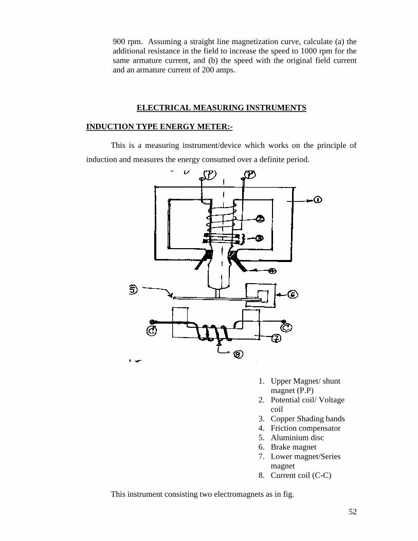
INDUCTION TYPE ENERGY METER:-
This is a measuring instrument/device which works on the principle of
induction and measures the energy consumed over a definite period.
1. Upper Magnet/ shuntmagnet (P.P)
2. Potential coil/ Voltagecoil
3. Copper Shading bands4. Friction compensator5. Aluminium disc6. Brake magnet7. Lower magnet/Series
magnet8. Current coil (C-C)
This instrument consisting two electromagnets as in fig.
53
1. Upper magnet or Shunt magnet: which carries the potential coil on its
central limb which also carries one or two copper shading bands for the
power factor adjustment.
2. Lower magnet or Series magnet: Which carries the current coil as
shown.
An aluminum disc is between the fields of the upper and lower electro
magnets. There is a friction compensator in the upper magnets for the
measurement at very low loads. The aluminum disc rotates in the field of a
brake magnet whose position can be set so that the disc rotates at proper
speeds at higher loads.
This instrument works on the principle of induction that when both the
shunt and series coils are energized by ac, there will be tow alternative
fluxes are in the shunt coil and one in the series coil these time varying
fluxes are cut by a stationary disc. Inducing currents in the disc. These
currents interacts with the fluxes and results in a torque which is given by
shsesesh iKikT 21 there by the disc rotates in a particular direction
and the number and speed of rotations depends on the energy consumed
by the load.
Some times the energy meters disc rotates slowly even on no load
conditions as the potential coil is continuously energized and this effect is
called the ‘CREEP’ and the speed is called the ‘CREEP SPEED’ to
minimum this creep one pair of diametrically opposite holes are made in
the aluminum disc which alters the reluctance and minimizes the creep
effect.
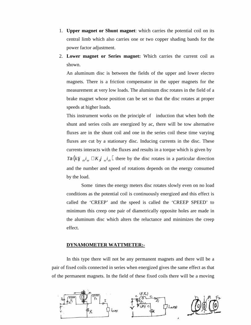
DYNAMOMETER WATTMETER:-
In this type there will not be any permanent magnets and there will be a
pair of fixed coils connected in series when energized gives the same effect as that
of the permanent magnets. In the field of these fixed coils there will be a moving
54
coil which when energized acted upon by a torque by which it deflects
F1 F2: Fixed coils
M: Moving coil
R: High resistance in series
with m
I1 : load current
I2: current through
The two fixed coils in series act as the current coil and the moving coil in series
with R act as the potential coil. The moving coil is pivoted between the two fixed
coils carries a current I2 proportional to V. This current is fed to m through two
springs which also provides the necessary controlling torque. This instrument can
be used on both ac and dc circuits as both the coils are energized simultaneously
by a common source due to which a unidirectional torque is produced.
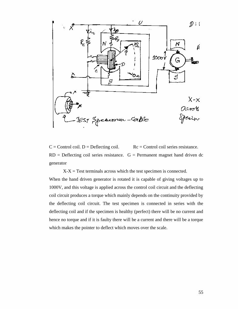
MEGGER: It is a portable instrument used for testing the insulation resistance of
a circuit and for the measurement of high resistances of the order of mega ohms.
This is a moving coil type of instrument having two coils rigidly connected to
each other with their planes set at right angles to each other. These two coils are
under the field of a permanent magnet and there coils are energized by a
permanent magnet hand driven dc generator as shown in fig.
55
C = Control coil. D = Deflecting coil. Rc = Control coil series resistance.
RD = Deflecting coil series resistance. G = Permanent magnet hand driven dc
generator
X-X = Test terminals across which the test specimen is connected.
When the hand driven generator is rotated it is capable of giving voltages up to
1000V, and this voltage is applied across the control coil circuit and the deflecting
coil circuit produces a torque which mainly depends on the continuity provided by
the deflecting coil circuit. The test specimen is connected in series with the
deflecting coil and if the specimen is healthy (perfect) there will be no current and
hence no torque and if it is faulty there will be a current and there will be a torque
which makes the pointer to deflect which moves over the scale.
56
ELE-15/25. BASIC ELECTRICAL ENGINEERING
CHAPTER-I ELECTROMAGNETISM.Faraday’s Law, Lenz’s Law, Fleming’s rules, statically and dynamically inducedEMF, concept of self and mutual inductance, energy stored in magnetic field.…………………………………………………………………………………………..Objectives- To learn about magnetism and Electromagnetismwhich is the
pre requisite for studying the machine theory.To start with we should know the basics of magnetic circuits.
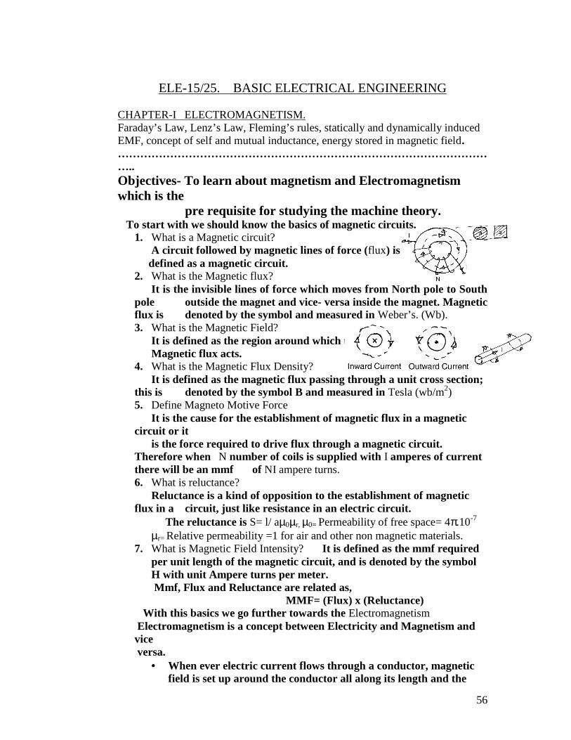
1. What is a Magnetic circuit?A circuit followed by magnetic lines of force (flux) is
defined as a magnetic circuit.2. What is the Magnetic flux?
It is the invisible lines of force which moves from North pole to Southpole outside the magnet and vice- versa inside the magnet. Magneticflux is denoted by the symbol and measured in Weber’s. (Wb).3. What is the Magnetic Field?
It is defined as the region around which theMagnetic flux acts.
4. What is the Magnetic Flux Density?It is defined as the magnetic flux passing through a unit cross section;
this is denoted by the symbol B and measured in Tesla (wb/m2)5. Define Magneto Motive Force
It is the cause for the establishment of magnetic flux in a magneticcircuit or it
is the force required to drive flux through a magnetic circuit.Therefore when N number of coils is supplied with I amperes of currentthere will be an mmf of NI ampere turns.6. What is reluctance?
Reluctance is a kind of opposition to the establishment of magneticflux in a circuit, just like resistance in an electric circuit.
The reluctance is S= l/ a0r, 0= Permeability of free space= 4.10-7
r= Relative permeability =1 for air and other non magnetic materials.7. What is Magnetic Field Intensity? It is defined as the mmf required
per unit length of the magnetic circuit, and is denoted by the symbolH with unit Ampere turns per meter.Mmf, Flux and Reluctance are related as,
MMF= (Flux) x (Reluctance)With this basics we go further towards the Electromagnetism
Electromagnetism is a concept between Electricity and Magnetism andviceversa.
When ever electric current flows through a conductor, magneticfield is set up around the conductor all along its length and the
57
flux lines are in the form of concentric circles around theconductor and the direction of the field depends on the direction ofthe electric current in the conductor.
Magnetic field strength is proportional to the current and isstronger near the conductor.
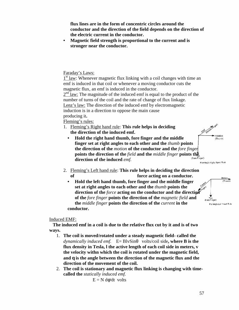
Faraday’s Laws:1st law: Whenever magnetic flux linking with a coil changes with time anemf is induced in that coil or whenever a moving conductor cuts themagnetic flux, an emf is induced in the conductor.2nd law: The magnitude of the induced emf is equal to the product of thenumber of turns of the coil and the rate of change of flux linkage.Lenz’s law: The direction of the induced emf by electromagneticinduction is in a direction to oppose the main causeproducing it.Fleming’s rules:1. Fleming’s Right hand rule: This rule helps in deciding
the direction of the induced emf. Hold the right hand thumb, fore finger and the middle
finger set at right angles to each other and the thumb pointsthe direction of the motion of the conductor and the fore fingerpoints the direction of the field and the middle finger points thedirection of the induced emf.
2. Fleming’s Left hand rule: This rule helps in deciding the directionof force acting on a conductor.
Hold the left hand thumb, fore finger and the middle fingerset at right angles to each other and the thumb points thedirection of the force acting on the conductor and the directionof the fore finger points the direction of the magnetic field andthe middle finger points the direction of the current in the
conductor.
Induced EMF:The induced emf in a coil is due to the relative flux cut by it and is of two
ways.1. The coil is moved/rotated under a steady magnetic field- called the
dynamically induced emf. E= BlvSin volts/coil side, where B is theflux density in Tesla, l the active length of each coil side in meters, vthe velocity withn which the coil is rotated under the magnetic field,and is the angle between the direction of the magnetic flux and thedirection of the movement of the coil.
2. The coil is stationary and magnetic flux linking is changing with time-called the statically induced emf.
E = N d/dt volts
58
Self inductance: (L Henry): It is defined as the property of a coil to opposeany change in current.OR It is the property of a coil to induce an emf in it when there is achange in current with time.
E= L di/dt volts
OR It is the property of a coil to store energy in a magnetic field.Energy= ½ LI2 Joules.
OR Self inductance is also defined as the change in flux linkage per unitampere of current change in it.
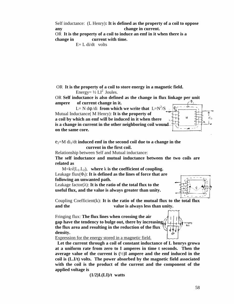
L= N d /di from which we write that L=N2/SMutual Inductance( M Henry): It is the property ofa coil by which an emf will be induced in it when thereis a change in current in the other neighboring coil woundon the same core.
e2=M di1/dt induced emf in the second coil due to a change in thecurrent in the first coil.
Relationship between Self and Mutual inductance:The self inductance and mutual inductance between the two coils arerelated as
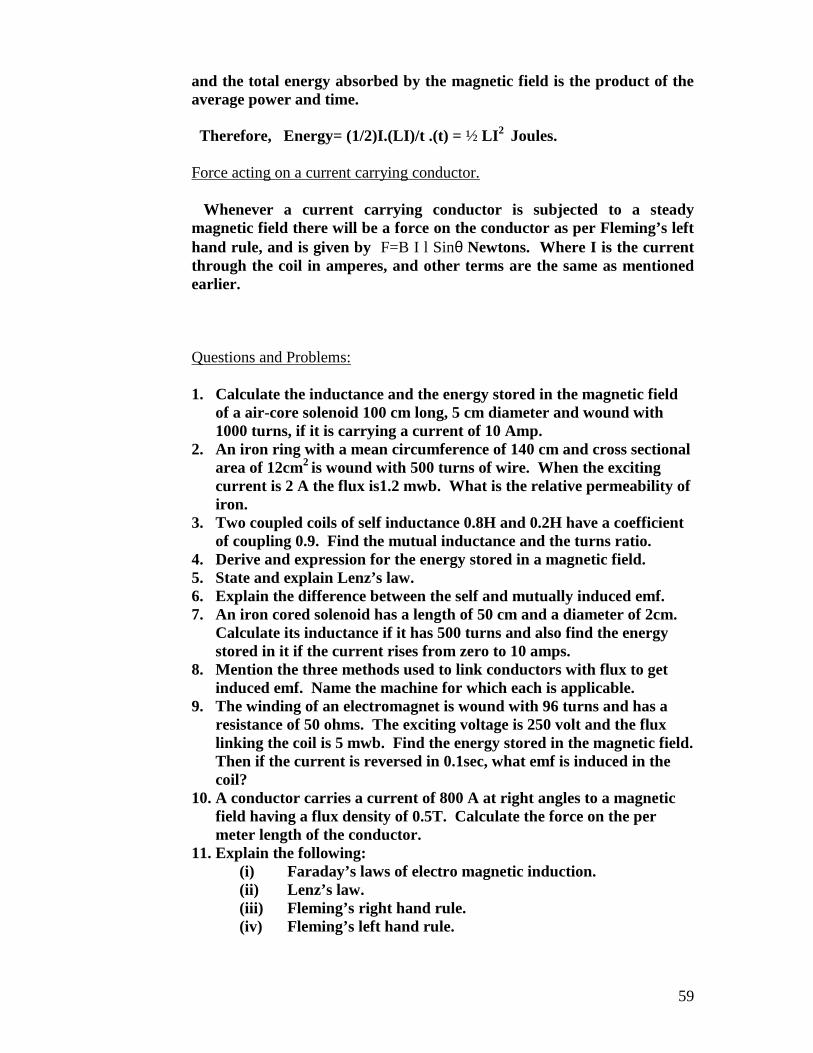
M=k(L1.L2), where k is the coefficient of coupling.Leakage flux(Φl): It is defined as the lines of force that arefollowing an unwanted path.Leakage factor(λ): It is the ratio of the total flux to theuseful flux, and the value is always greater than unity.
Coupling Coefficient(k): It is the ratio of the mutual flux to the total fluxand the value is always less than unity.
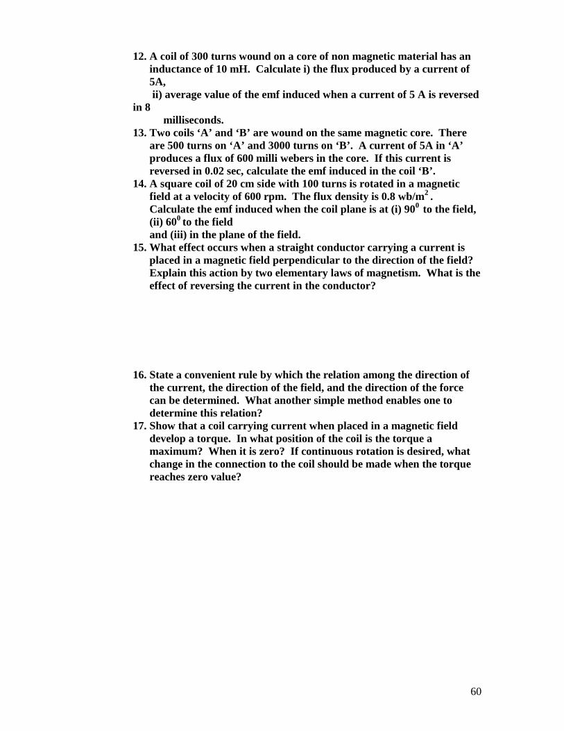
Fringing flux: The flux lines when crossing the airgap have the tendency to bulge out, there by increasingthe flux area and resulting in the reduction of the fluxdensity.Expression for the energy stored in a magnetic field.
Let the current through a coil of constant inductance of L henrys growaat a uniform rate from zero to I amperes in time t seconds. Then theaverage value of the current is (½)I ampere and the emf induced in thecoil is (L.I/t) volts. The power absorbed by the magnetic field associatedwith the coil is the product of the current and the component of theapplied voltage is
(1/2)I.(LI)/t watts
59
and the total energy absorbed by the magnetic field is the product of theaverage power and time.
Therefore, Energy= (1/2)I.(LI)/t .(t) = ½ LI2 Joules.
Force acting on a current carrying conductor.
Whenever a current carrying conductor is subjected to a steadymagnetic field there will be a force on the conductor as per Fleming’s lefthand rule, and is given by F=B I l Sin Newtons. Where I is the currentthrough the coil in amperes, and other terms are the same as mentionedearlier.
Questions and Problems:
1. Calculate the inductance and the energy stored in the magnetic fieldof a air-core solenoid 100 cm long, 5 cm diameter and wound with1000 turns, if it is carrying a current of 10 Amp.
2. An iron ring with a mean circumference of 140 cm and cross sectionalarea of 12cm2 is wound with 500 turns of wire. When the excitingcurrent is 2 A the flux is1.2 mwb. What is the relative permeability ofiron.
3. Two coupled coils of self inductance 0.8H and 0.2H have a coefficientof coupling 0.9. Find the mutual inductance and the turns ratio.
4. Derive and expression for the energy stored in a magnetic field.5. State and explain Lenz’s law.6. Explain the difference between the self and mutually induced emf.7. An iron cored solenoid has a length of 50 cm and a diameter of 2cm.
Calculate its inductance if it has 500 turns and also find the energystored in it if the current rises from zero to 10 amps.
8. Mention the three methods used to link conductors with flux to getinduced emf. Name the machine for which each is applicable.
9. The winding of an electromagnet is wound with 96 turns and has aresistance of 50 ohms. The exciting voltage is 250 volt and the fluxlinking the coil is 5 mwb. Find the energy stored in the magnetic field.Then if the current is reversed in 0.1sec, what emf is induced in thecoil?
10. A conductor carries a current of 800 A at right angles to a magneticfield having a flux density of 0.5T. Calculate the force on the permeter length of the conductor.
11. Explain the following:(i) Faraday’s laws of electro magnetic induction.(ii) Lenz’s law.(iii) Fleming’s right hand rule.(iv) Fleming’s left hand rule.
60
12. A coil of 300 turns wound on a core of non magnetic material has aninductance of 10 mH. Calculate i) the flux produced by a current of5A,ii) average value of the emf induced when a current of 5 A is reversed
in 8milliseconds.
13. Two coils ‘A’ and ‘B’ are wound on the same magnetic core. Thereare 500 turns on ‘A’ and 3000 turns on ‘B’. A current of 5A in ‘A’produces a flux of 600 milli webers in the core. If this current isreversed in 0.02 sec, calculate the emf induced in the coil ‘B’.
14. A square coil of 20 cm side with 100 turns is rotated in a magneticfield at a velocity of 600 rpm. The flux density is 0.8 wb/m2 .Calculate the emf induced when the coil plane is at (i) 900 to the field,(ii) 600 to the fieldand (iii) in the plane of the field.
15. What effect occurs when a straight conductor carrying a current isplaced in a magnetic field perpendicular to the direction of the field?Explain this action by two elementary laws of magnetism. What is theeffect of reversing the current in the conductor?
16. State a convenient rule by which the relation among the direction ofthe current, the direction of the field, and the direction of the forcecan be determined. What another simple method enables one todetermine this relation?
17. Show that a coil carrying current when placed in a magnetic fielddevelop a torque. In what position of the coil is the torque amaximum? When it is zero? If continuous rotation is desired, whatchange in the connection to the coil should be made when the torquereaches zero value?
61
18. Fundamentally, upon what two quantities does the speed of the motordepend? Derive the equation which gives the speed in terms ofterminal voltage, armature resistance drop, and the flux per pole.
19. When load is applied to a motor what is its first reaction? With theshuntMotor, how does this reaction affect the counter emf ? The current tothe armature?
20. How does the flux in series motor vary with the load current? Showthe relation of internal torque to load current, assuming no saturationin the magnetic circuit. Show the relation of speed to load current.What precautions should be taken when the series motor is beinginstalled for industrial drives?
21. In what way do the windings of a compound motor differ from thoseof a shunt motor and a series motor? In what two ways, with respectto the shunt winding, may the series winding be connected?
22. Discuss the speed characteristic and torque characteristic of thecumulative-compound motor. What is the advantage of this motorover the series motor?
23. Why is a starting resistance necessary for d.c. motors? With theshunt motor, in what circuit the starting resistor is connected? Whyshould it not be connected in the line?
24. The resistance of the armature of a 25-hp 240-volt shunt motor is0.083 ohm. When connected to a 240-volt supply the armaturedevelops a counter emf of 232.8-volts. Determine: (a) armaturecurrent; (b) armature current when connected across same powersupply while stationary; (c) counter emf when armature current is 110amperes.
25. A 23-volt 4-pole 15 hp shunt motor has 702 conductors connected forsimplex wave and its resistance is 0.252 ohm. The flux per pole is 7.65milliwebers and the armature current is 60-Amp. Determine speed ofarmature.
26. A four pole d.c. shunt motor has 456 surface conductors connected insimplex wave. The flux is 2.41 milliwebers per pole (a) Determine thecounter emf when the speed is 1500 rpm. The armature resistance is0.2 ohm. (b) Determine the terminal voltage when armature current is60-amp if the speed and flux remain constant.
27. A 60-hp, 250-volt, 1200 rpm shunt motor takes 214 amp at 250 volts.The field current is 1.05 amp, and the combined total armatureresistance is 0.039 ohm. The motor speed when running light is 1200rpm, and the line current is 8.6 amp. Determine the internal powerand torque developed.
28. A 25-hp, 250-volt d.c. series motor has its armature aand series fieldresistance of 0.12 ohm and 0.10 ohm respectively. When the motortakes 85 amp, the speed is 600 rpm. Determine the speed when thecurrent is (a) 100 amp, (b) 40 amp. Assume saturation curve is astraight line, and neglect armature reaction.
62
29. A 6 pole d.c. generator runs at 850 rpm, and each pole has a flux of0.2 milliwebers. If there are 150 conductors in series between eachpair of brushes, what is the value of the generated emf.?
30. A 2240-volt shunt motor has a field resistance of 400 ohm and anarmature resistance of 0.1 ohm. The armature current is 50 amps,and the speed is 900 rpm. Assuming a straight line magnetizationcurve, calculate (a) the additional resistance in the field to increase thespeed to 1000 rpm for the same armature current, and (b) the speedwith the original field current and an armature current of 200 amps.
31.
Typical Questions of Basic Electrical Engineering.1. Define the coefficient of inductance of a magnetic circuit and show that
it isproportional to the square of the magnetizing turns and inversely to thereluctance.Define the terms “Magneto motive force”, “Magnetic Flux” and “MagneticReluctance” and prove the relation which holds between these quantitiesfor a magnetic circuit.
2. Two coils have a coupling coefficient k=0.85 and coil 1 has 250 turns.With a current i1=2A in coil 1, the total flux is 0.3 wb. When i1 isreduced linearly to zero in two milliseconds the voltage induced in coil2 is 63.75 volts. Find L1, L2, M and N2.
3. Two coupled coils with turns N1=100 and N2=800 have a couplingcoefficientof 0.85. With coil 1 open and a current of 5 amperes in coil 2, the flux Ф2
is 0.35 mwb. Find L1, L2 and M.
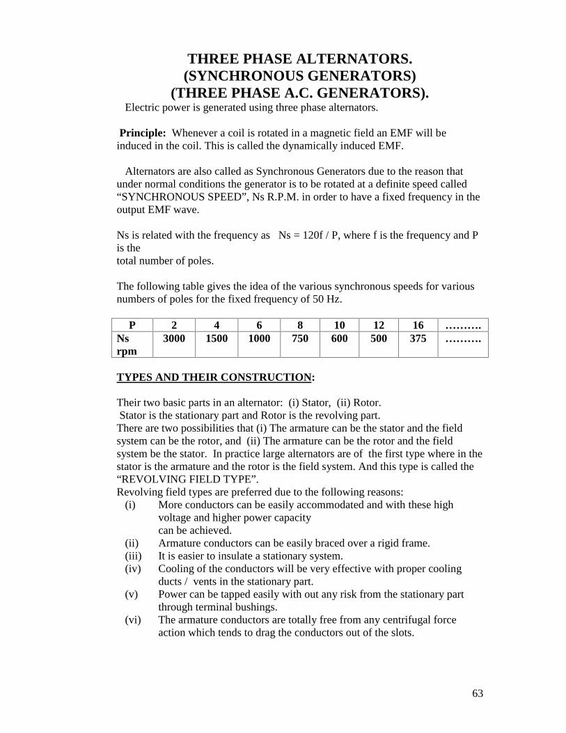
63
THREE PHASE ALTERNATORS.(SYNCHRONOUS GENERATORS)
(THREE PHASE A.C. GENERATORS).Electric power is generated using three phase alternators.
Principle: Whenever a coil is rotated in a magnetic field an EMF will beinduced in the coil. This is called the dynamically induced EMF.
Alternators are also called as Synchronous Generators due to the reason thatunder normal conditions the generator is to be rotated at a definite speed called“SYNCHRONOUS SPEED”, Ns R.P.M. in order to have a fixed frequency in theoutput EMF wave.
Ns is related with the frequency as Ns = 120f / P, where f is the frequency and Pis thetotal number of poles.
The following table gives the idea of the various synchronous speeds for variousnumbers of poles for the fixed frequency of 50 Hz.
P 2 4 6 8 10 12 16 ……….Nsrpm
3000 1500 1000 750 600 500 375 ……….
TYPES AND THEIR CONSTRUCTION:
Their two basic parts in an alternator: (i) Stator, (ii) Rotor.Stator is the stationary part and Rotor is the revolving part.
There are two possibilities that (i) The armature can be the stator and the fieldsystem can be the rotor, and (ii) The armature can be the rotor and the fieldsystem be the stator. In practice large alternators are of the first type where in thestator is the armature and the rotor is the field system. And this type is called the“REVOLVING FIELD TYPE”.Revolving field types are preferred due to the following reasons:
(i) More conductors can be easily accommodated and with these highvoltage and higher power capacitycan be achieved.
(ii) Armature conductors can be easily braced over a rigid frame.(iii) It is easier to insulate a stationary system.(iv) Cooling of the conductors will be very effective with proper cooling
ducts / vents in the stationary part.(v) Power can be tapped easily with out any risk from the stationary part
through terminal bushings.(vi) The armature conductors are totally free from any centrifugal force
action which tends to drag the conductors out of the slots.
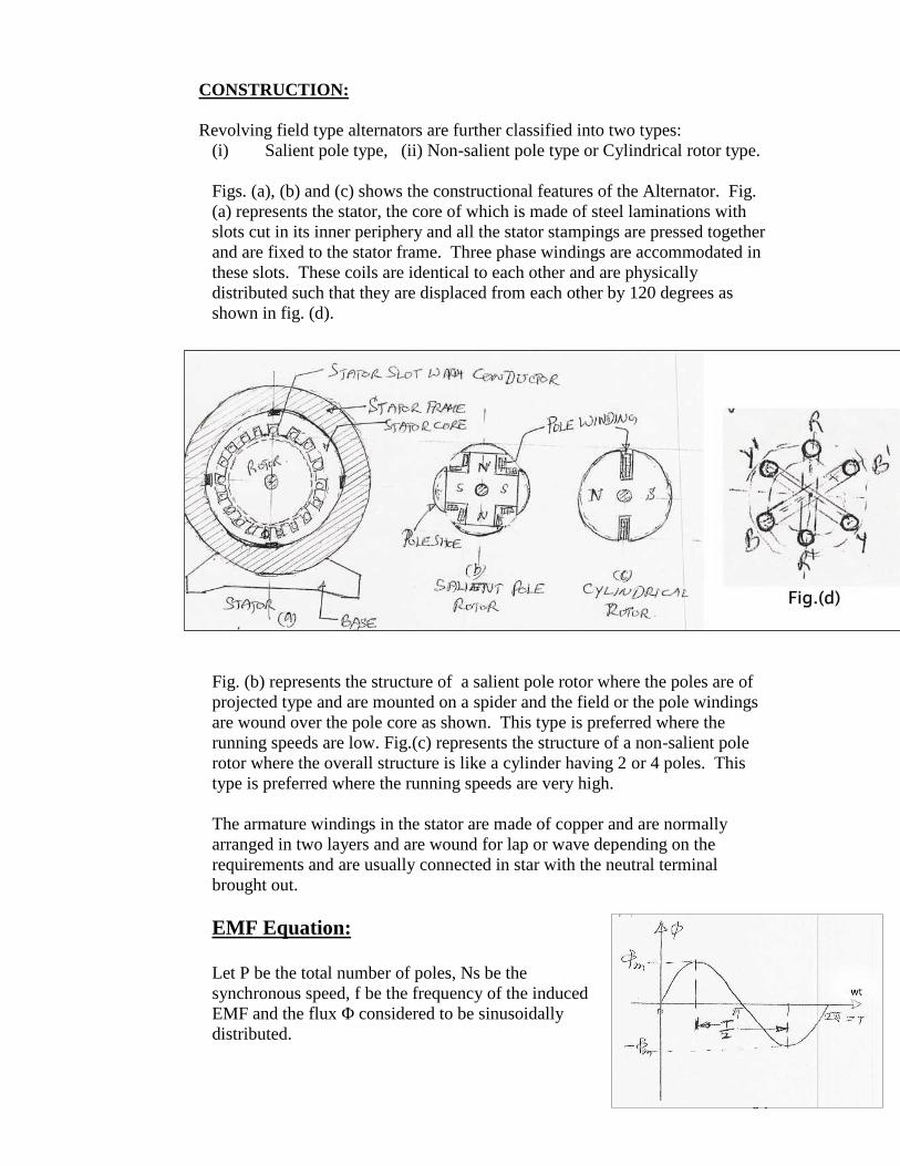
64
CONSTRUCTION:
Revolving field type alternators are further classified into two types:(i) Salient pole type, (ii) Non-salient pole type or Cylindrical rotor type.
Figs. (a), (b) and (c) shows the constructional features of the Alternator. Fig.(a) represents the stator, the core of which is made of steel laminations withslots cut in its inner periphery and all the stator stampings are pressed togetherand are fixed to the stator frame. Three phase windings are accommodated inthese slots. These coils are identical to each other and are physicallydistributed such that they are displaced from each other by 120 degrees asshown in fig. (d).
Fig. (b) represents the structure of a salient pole rotor where the poles are ofprojected type and are mounted on a spider and the field or the pole windingsare wound over the pole core as shown. This type is preferred where therunning speeds are low. Fig.(c) represents the structure of a non-salient polerotor where the overall structure is like a cylinder having 2 or 4 poles. Thistype is preferred where the running speeds are very high.
The armature windings in the stator are made of copper and are normallyarranged in two layers and are wound for lap or wave depending on therequirements and are usually connected in star with the neutral terminalbrought out.
EMF Equation:
Let P be the total number of poles, Ns be thesynchronous speed, f be the frequency of the inducedEMF and the flux Φ considered to be sinusoidallydistributed.
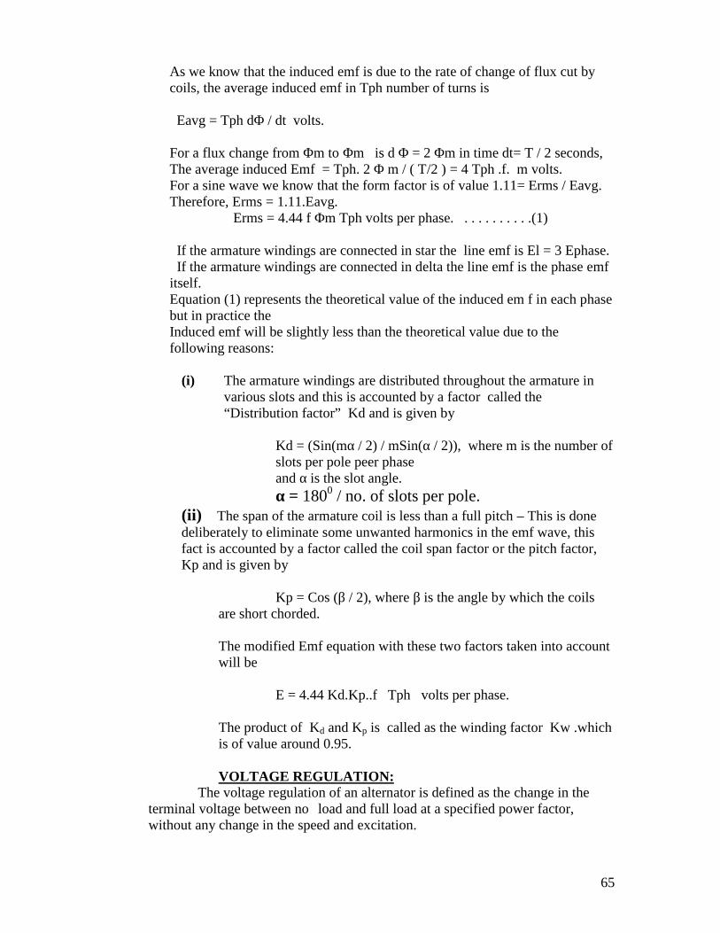
65
As we know that the induced emf is due to the rate of change of flux cut bycoils, the average induced emf in Tph number of turns is
Eavg = Tph dΦ / dt volts.
For a flux change from Φm to Φm is d Φ = 2 Φm in time dt= T / 2 seconds,The average induced Emf = Tph. 2 Φ m / ( T/2 ) = 4 Tph .f. m volts.For a sine wave we know that the form factor is of value 1.11= Erms / Eavg.Therefore, Erms = 1.11.Eavg.
Erms = 4.44 f Φm Tph volts per phase. . . . . . . . . . .(1)
If the armature windings are connected in star the line emf is El = 3 Ephase.If the armature windings are connected in delta the line emf is the phase emf
itself.Equation (1) represents the theoretical value of the induced em f in each phasebut in practice theInduced emf will be slightly less than the theoretical value due to thefollowing reasons:
(i) The armature windings are distributed throughout the armature invarious slots and this is accounted by a factor called the“Distribution factor” Kd and is given by
Kd = (Sin(mα / 2) / mSin(α / 2)), where m is the number ofslots per pole peer phaseand α is the slot angle.α = 1800 / no. of slots per pole.
(ii) The span of the armature coil is less than a full pitch – This is donedeliberately to eliminate some unwanted harmonics in the emf wave, thisfact is accounted by a factor called the coil span factor or the pitch factor,Kp and is given by
Kp = Cos (β / 2), where β is the angle by which the coilsare short chorded.
The modified Emf equation with these two factors taken into accountwill be
E = 4.44 Kd.Kp..f Tph volts per phase.
The product of Kd and Kp is called as the winding factor Kw .whichis of value around 0.95.
VOLTAGE REGULATION:The voltage regulation of an alternator is defined as the change in the
terminal voltage between no load and full load at a specified power factor,without any change in the speed and excitation.
66
(No load terminal voltage – Full load terminal voltage)% Voltage regulation = ----------------------------------------------------------------
----- x 100Full load terminal voltage
E – V% Voltage regulation = -------- x 100
V
The idea of voltage regulation is necessary to judge the performance of analternator. Lesser the value of the regulation better will be the load sharingcapacity at better efficiency.
PROBLEMS:
1. The stator of a three phase, 8 pole, 750 rpm alternator has 72 slots, each ofwhich having 10 conductors. Calculate the RMS value of the emf perphase if the flux per pole is 0.1 wb and the winding factor is 0.96. Alsofind the line Emf if the windings are connected in (i) Star, and (ii) Delta.
2. A three phase star connected alternator driven at 900 rpm is required togenerate a line voltage of 460 volts at 60 Hz on open circuit. The statorhas 2 slots per pole per phase and 4 conductors per slot. Calculate (i) thenumber of poles, (ii) the useful flux per pole.
3. A 4 pole, three phase, 50 Hz, star connected a.c. generator has 24 statorslots. Find the number of conductors per slot if the flux per pole is 62mwb and the terminal voltage is 1100 volt. Assume full pitch coils.
4. A 16 pole star connected alternator has 144 slots and 10 conductors perslot. The flux per pole is 30 mwb and the speed is 375 rpm. Find thefrequency, the phase and line emf’s.
5. Find the number of armature conductors in series per phase required forthe armature of a three phase50 Hz 10 pole alternator with 90 slots. The winding is star connected togive a line emf of 11 Kv. The flux is 0.16 wb. Also find the voltageregulation if the terminal voltage on full load is 11.2 kv.
6. A three phase 10 pole star connected alternator runs at 600 rpm. It has120 stator slots with 8 conductors per slot. Determine the phase and lineemf’s if the flux per pole is 56 mwb.
7. Calculate the phase emf induced in a 4 pole, three phase, 50 Hz starconnected alternator with 36 slots and 30 conductors per slot. The flux perpole is 0.05 wb. Given the winding factor as 0.95.
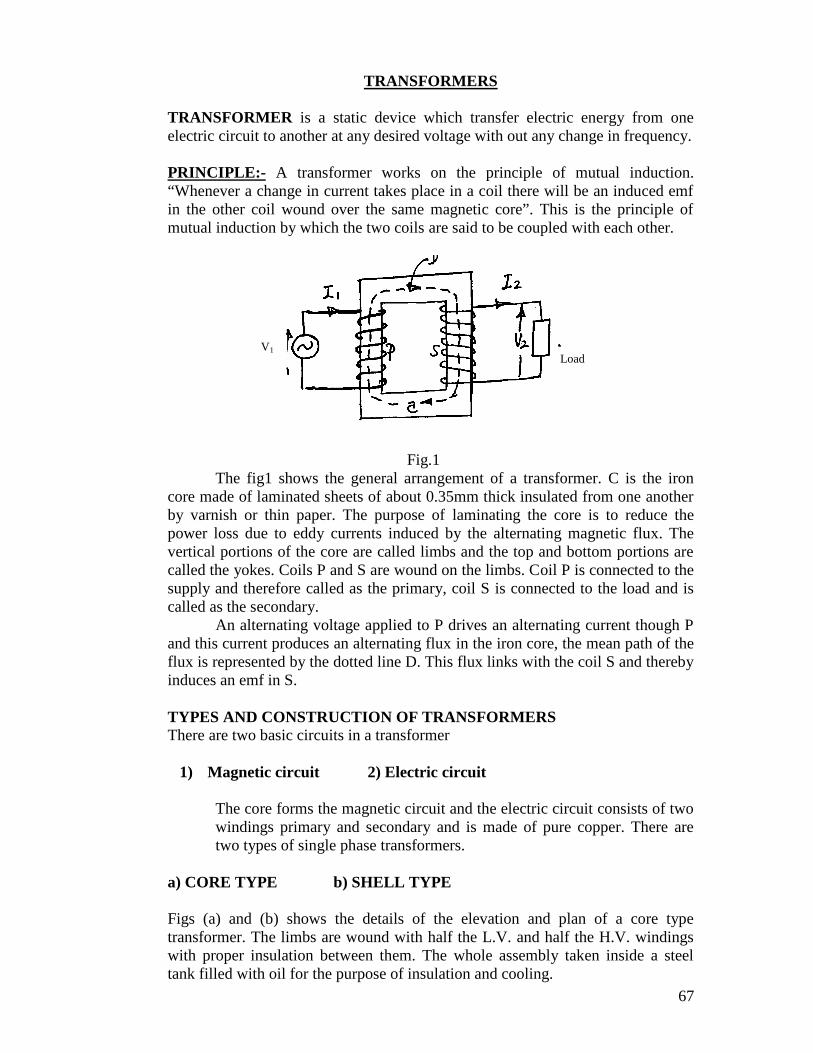
67
TRANSFORMERS
TRANSFORMER is a static device which transfer electric energy from oneelectric circuit to another at any desired voltage with out any change in frequency.
PRINCIPLE:- A transformer works on the principle of mutual induction.“Whenever a change in current takes place in a coil there will be an induced emfin the other coil wound over the same magnetic core”. This is the principle ofmutual induction by which the two coils are said to be coupled with each other.
Fig.1The fig1 shows the general arrangement of a transformer. C is the iron
core made of laminated sheets of about 0.35mm thick insulated from one anotherby varnish or thin paper. The purpose of laminating the core is to reduce thepower loss due to eddy currents induced by the alternating magnetic flux. Thevertical portions of the core are called limbs and the top and bottom portions arecalled the yokes. Coils P and S are wound on the limbs. Coil P is connected to thesupply and therefore called as the primary, coil S is connected to the load and iscalled as the secondary.
An alternating voltage applied to P drives an alternating current though Pand this current produces an alternating flux in the iron core, the mean path of theflux is represented by the dotted line D. This flux links with the coil S and therebyinduces an emf in S.
TYPES AND CONSTRUCTION OF TRANSFORMERSThere are two basic circuits in a transformer
1) Magnetic circuit 2) Electric circuit
The core forms the magnetic circuit and the electric circuit consists of twowindings primary and secondary and is made of pure copper. There aretwo types of single phase transformers.
a) CORE TYPE b) SHELL TYPE
Figs (a) and (b) shows the details of the elevation and plan of a core typetransformer. The limbs are wound with half the L.V. and half the H.V. windingswith proper insulation between them. The whole assembly taken inside a steeltank filled with oil for the purpose of insulation and cooling.
V1Load
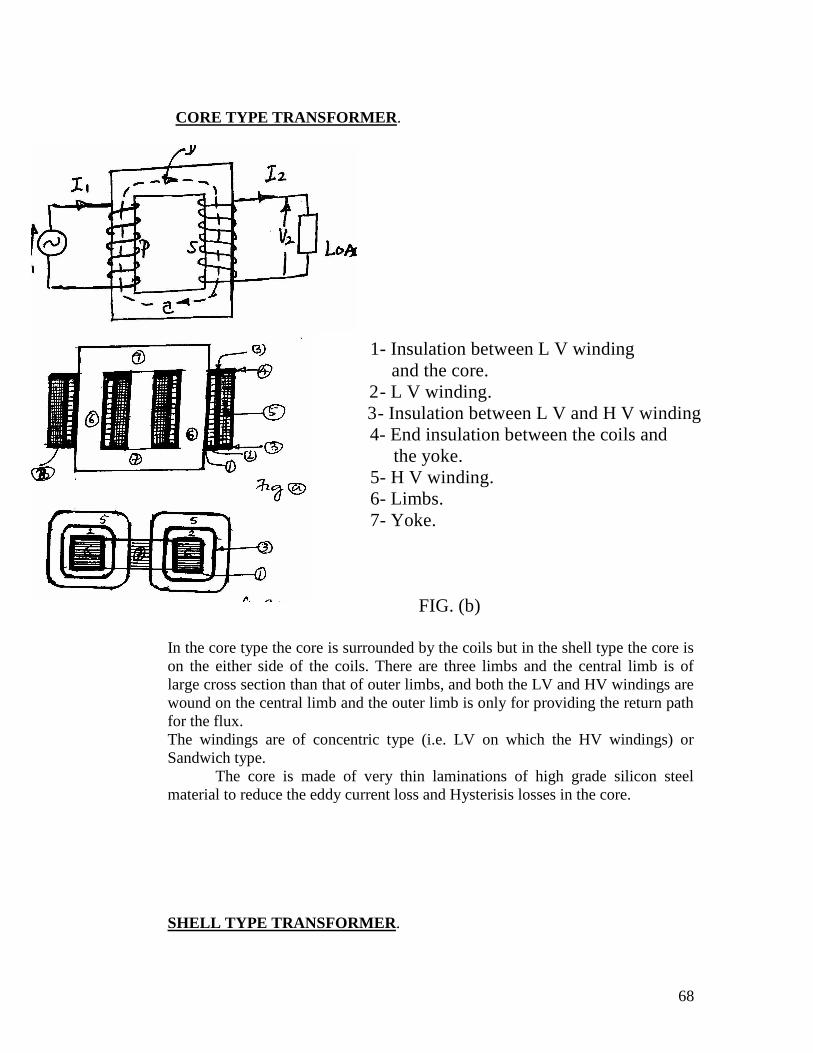
68
CORE TYPE TRANSFORMER.
In the core type the core is surrounded by the coils but in the shell type the core ison the either side of the coils. There are three limbs and the central limb is oflarge cross section than that of outer limbs, and both the LV and HV windings arewound on the central limb and the outer limb is only for providing the return pathfor the flux.The windings are of concentric type (i.e. LV on which the HV windings) orSandwich type.
The core is made of very thin laminations of high grade silicon steelmaterial to reduce the eddy current loss and Hysterisis losses in the core.
SHELL TYPE TRANSFORMER.
2222222222222222222222222222222222
1- Insulation between L V windingand the core and the core. 2- L V winding.
3- Insulation between L V and H V winding winding. 4- End insulation between the coils and
the yoke.5- H V winding.6- Limbs.
` 7- Yoke.
FIG. (b)
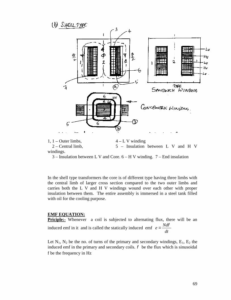
69
1, 1 – Outer limbs, 4 – L V winding2 – Central limb, 5 – Insulation between L V and H V
windings.3 – Insulation between L V and Core. 6 – H V winding. 7 – End insulation
In the shell type transformers the core is of different type having three limbs withthe central limb of larger cross section compared to the two outer limbs andcarries both the L V and H V windings wound over each other with properinsulation between them. The entire assembly is immersed in a steel tank filledwith oil for the cooling purpose.
EMF EQUATION:Priciple:- Whenever a coil is subjected to alternating flux, there will be an
induced emf in it and is called the statically induced emfdt
Nde
Let N1, N2 be the no. of turns of the primary and secondary windings, E1, E2 theinduced emf in the primary and secondary coils. be the flux which is sinusoidalf be the frequency in Hz
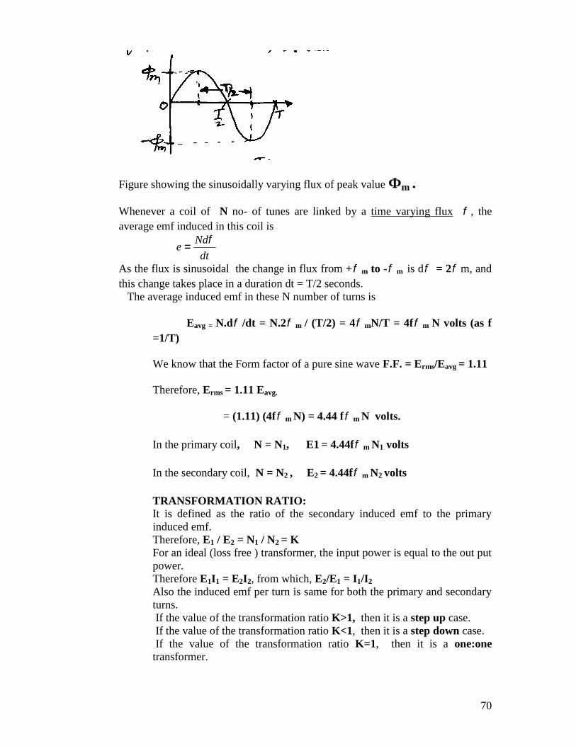
70
Figure showing the sinusoidally varying flux of peak value Фm .
Whenever a coil of N no- of tunes are linked by a time varying flux , theaverage emf induced in this coil is
dt
Nde
As the flux is sinusoidal the change in flux from + m to - m is d = 2 m, andthis change takes place in a duration dt = T/2 seconds.
The average induced emf in these N number of turns is
Eavg = N.d /dt = N.2 m / (T/2) = 4 mN/T = 4f m N volts (as f=1/T)
We know that the Form factor of a pure sine wave F.F. = Erms/Eavg = 1.11
Therefore, Erms = 1.11 Eavg.
= (1.11) (4f m N) = 4.44 f m N volts.
In the primary coil, N = N1, E1 = 4.44f m N1 volts
In the secondary coil, N = N2 , E2 = 4.44f m N2 volts
TRANSFORMATION RATIO:It is defined as the ratio of the secondary induced emf to the primaryinduced emf.Therefore, E1 / E2 = N1 / N2 = KFor an ideal (loss free ) transformer, the input power is equal to the out putpower.Therefore E1I1 = E2I2, from which, E2/E1 = I1/I2
Also the induced emf per turn is same for both the primary and secondaryturns.If the value of the transformation ratio K>1, then it is a step up case.If the value of the transformation ratio K<1, then it is a step down case.If the value of the transformation ratio K=1, then it is a one:one
transformer.
71
LOSSES AND EFFICIENCY: There a two types of power losses occur in atransformer
1) Iron loss 2) Copper loss
1) Iron Loss: This is the power loss that occurs in the iron part. This loss is due tothe alternating frequency of the emf. Iron loss in further classified into two otherlosses.
a) Eddy current loss b) Hysterisis loss
a) EDDY CURRENT LOSS: This power loss is due to the alternating fluxlinking the core, which will induced an emf in the core called the eddy emf, due towhich a current called the eddy current is being circulated in the core. As there issome resistance in the core with this eddy current circulation converts into heatcalled the eddy current power loss. Eddy current loss is proportional to the squareof the supply frequency.
b) HYSTERISIS LOSS: This is the loss in the iron core, due to the magneticreversal of the flux in the core, which results in the form of heat in the core. Thisloss is directly proportional to the supply frequency.
Eddy current loss can be minimized by using the core made of thin sheetsof silicon steel material, and each lamination is coated with varnish insulation tosuppress the path of the eddy currents.
Hysterisis loss can be minimized by using the core material having highpermeability.
2) COPPER LOSS: This is the power loss that occurs in the primary andsecondary coils when the transformer is on load. This power is wasted in the formof heat due to the resistance of the coils. This loss is proportional to the sequenceof the load hence it is called the Variable loss where as the Iron loss is called asthe Constant loss as the supply voltage and frequency are constants
EFFICENCY: It is the ratio of the out put power to the input power of atransformer
Input = Output + Total losses= Output + Iron loss + Copper loss
Efficiency =
coppereron WWIV
IV
copperlossIronlossroutputpowe
routputpowe
cos
cos
22
22
72
Where, V2 is the secondary (out put) voltage, I2 is the secondary (out put) currentand
cosФ is the power factor of the load.The transformers are normally specified with their ratings as KVA,
Therefore,
Efficiency= (KVA)(103) cosΦ----------------------------------------------
(KVA)(103) cosΦ + Wiron + Wcopper
Since the copper loss varies as the square of the load the efficiency of thetransformer at any desired load x is given by
Efficiency= x. (KVA)(103) cosΦ-------------------------------------------------
x. (KVA)(103) cosΦ + Wiron + (x)2 Wcopper
where Wcopper is the copper loss at full load
Wcopper = I2R watts
CONDITION FOR MAXIMUM EFFICIENCY:
In general for the efficiency to be maximum for any device the losses must beminimum. Between the iron and copper losses the iron loss is the fixed lossand the copper loss is the variable loss. When these two losses are equal andalso minimum the efficiency will be maximum.
Therefore the condition for maximum efficiency in a transformer is
Iron loss = Copper loss ( which ever is minimum)
VOLTAGE REGULATION:
The voltage regulation of a transformer is defined as the change in thesecondary terminal voltage between no load and full load at a specified powerfactor expressed as a percentage of the full load terminal voltage.
(percentage (No load secondary voltage)-(Full load secondary voltage)voltage = ---------------------------------------------------------------------------x 100regulation) (Full load secondary voltage)
Voltage regulation is a measure of the change in the terminal voltage of atransformer between No load and Full load. A good transformer has leastvalue of the regulation of the order of ±5%
73
Problems:
1. The required No load ratio of a single phase 50Hz, core type transformeris 6000/150v. Find the number of turns per limb on the high and lowvoltage sides if the flux is to be 0.06 wb.
2. A 125 KVA, single phase transformer has a primary voltage of 2000 v at60Hz. If the number of turns of the primary is 182 and secondary has 40
turns find (i) the secondary no load voltage (ii Flux in the core (iii) thefull load primary and secondary currents.
3. A 600 KVA, single phase transformer has an efficiency of 92% both atfull load and half full load at unity power factor. Determine theefficiency at 75% of full load and 0.9 power factor.
4. A 50KVA transformer has an efficiency of 98% at full load, 0.8 p.f. andan efficiency of 96.9% at 1/4th full load, u.p.f. Determine the iron loss andfull load copper loss.
5. In a 50KVA, 2000/200 v single phase transformer the iron loss and fullload copper losses area 700 w and 1000 W respectively. Calculate theefficiency of the transformer on full load and at half full load. The p.f.of the load is 0.75 lag.
6. A 5 KVA, 200/100 v, single phase, 50Hz transformer has a ratedsecondary voltage at full load. When the load is removed the secondaryvoltage is found to be 110 v. Determine the percentage voltageregulation.
7. A single phase transformer has 400 primary and 1000 secondary turns.The net cross sectional area of the core is 60 cm2. If the primary windingis connected to a 50Hz supply at 500v, calculate (i) the peak value of theflux density in the core (ii) the voltage induced in the secondary winding.
![Working with compiled code - bobby.gramacy.combobby.gramacy.com/teaching/asc/compiled.pdf · beta[b,]](https://img.dokumen.tips/doc/110x75/5a9d8b567f8b9a28388b7688/working-with-compiled-code-bobby-b-olsrxb-yb-uselmtrue-iceptfalse.jpg)

![6. Wiring Diagram - weidefamily.net coil Transmission control module ... WIRING DIAGRAM 6. Wiring Diagram. MEMO: 21 WIRING DIAGRAM ... 76 6-3 [D6R2] WIRING DIAGRAM 6](https://img.dokumen.tips/doc/110x75/5aa0cc3b7f8b9a62178ea5e7/6-wiring-diagram-coil-transmission-control-module-wiring-diagram-6-wiring.jpg)
![5. Wiring Diagram - Subaru Forester. Wiring Diagram A: POWER SUPPLY ROUTING SU01-04A 12 6-3 [D5A0] WIRING DIAGRAM 5. Wiring Diagram SU01-04B 13 WIRING DIAGRAM [D5A0] 6-3 5. Wiring](https://img.dokumen.tips/doc/110x75/5aa205fe7f8b9a1f6d8cac3f/5-wiring-diagram-subaru-wiring-diagram-a-power-supply-routing-su01-04a-12.jpg)


![85RX7(50)Wiring Diagrams - wright-here.net50)Wiring_Di… · Symbol in this wiring diagram Parts index Electrical wiring schematic . . . [For 12A Engine] Electrical wiring schematic](https://img.dokumen.tips/doc/110x75/60618b736d48e7606d322842/85rx750wiring-diagrams-wright-here-50wiringdi-symbol-in-this-wiring-diagram.jpg)