Embed Size (px)
Citation preview

8/8/2019 DPW LP Conversion 10-15-2008
http://slidepdf.com/reader/full/dpw-lp-conversion-10-15-2008 1/8
DPW LP Gas Conversion InstructionsLP Kit Contents
DPW-099/120A
Manifold Assembly 1.03 Nozzle Red Sticker on the ManifoldO Rings 1 includedManifold Gasket 1 includedHX Gasket 2 strips, self adhesiveLP Sticker To be attached to rating plate
Tools required Philips head screwdriverCrescent wrenchKnife, gasket removerSoapy bubblesGas Manometer

8/8/2019 DPW LP Conversion 10-15-2008
http://slidepdf.com/reader/full/dpw-lp-conversion-10-15-2008 2/8
2
Conversion of an appliance from Natural to LP Gas must only be done by atrained, and where applicable licensed technician.Failure to follow these instructions may result in explosion causing either death orserious injury.If in doubt regarding these instructions please contact Quietside TechnicalSupport for assistance.
Once unit is converted sticker must be applied to the rating plate showing thatgas supply has been converted
LP Conversion sequence
Step1Disconnect Power to unit, and turn off gas supply.Remove front panel from the unit (4 Philips screws)
Step 2Remove white wires from Igniter and Flame Sensor.Remove 4 Philips screws attaching retaining plate and carefully remove theIgniter/Flame Sensor assembly from the unit.
Igniter is mounted on Left Side of assembly and has a pink mark to identify itFlame Sensor is mounted on Right side of assembly.
8/8/2019 DPW LP Conversion 10-15-2008
http://slidepdf.com/reader/full/dpw-lp-conversion-10-15-2008 3/8
3
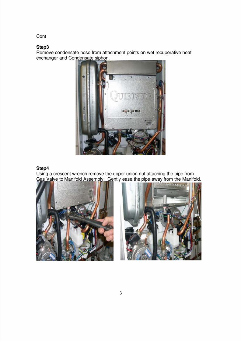
Cont
Step3Remove condensate hose from attachment points on wet recuperative heat
exchanger and Condensate siphon.
Step4Using a crescent wrench remove the upper union nut attaching the pipe from
Gas Valve to Manifold Assembly. Gently ease the pipe away from the Manifold.

8/8/2019 DPW LP Conversion 10-15-2008
http://slidepdf.com/reader/full/dpw-lp-conversion-10-15-2008 4/8
4
Cont
Step 5Remove Philips screws holding Combustion Chamber Front panel and carefully
remove panel, trying not to tear gasket.Note : If Gasket material attached to the panel does tear, remove all gasketmaterial using a knife blade and replace with gasket material supplied in the kit.
Step 6With burner assembly exposed, remove the two Philips head screws attachingthe manifold to the combustion chamber.
Ground Wire

8/8/2019 DPW LP Conversion 10-15-2008
http://slidepdf.com/reader/full/dpw-lp-conversion-10-15-2008 5/8
5
Cont
Step 7Gently remove the manifold from the unit
Step 8Take new LP Gas Manifold from kit, and attach new seal gasket in groovedchannel
LP Gas Manifold will be stamped with gas type and orifice size, check manifoldagainst the specifications provided to ensure correct manifold has been providedfor your specific unit.

8/8/2019 DPW LP Conversion 10-15-2008
http://slidepdf.com/reader/full/dpw-lp-conversion-10-15-2008 6/8
6
Cont
Step 9Slide LP Manifold assembly back into the unit.
Locating pins of the Manifold will help guide it into the correct orientation.Make sure that the gasket seals between Combustion Chamber and Manifold.
Step 10Replace O ring from Gas Valve Pipe/Manifold connection with new one from LPKit.Align Gas Valve Pipe to the Manifold and hand tighten union nut.Make sure the Union nut tightens freely to prevent cross threading.Once tight, use crescent wrench to fully tighten.
Make sure nut is tight on Manifold Assembly to ensure a full seal betweenthe Gas Valve Pipe and the Manifold.
THIS PROCEDURE IS EXTREMELY IMPORTANT AS INCORRECTASSEMBLY COULD ALLOW GAS TO LEAK FROM THIS JOINT
After Manifold is attached to Gas Valve Pipe then attach Manifold to CombustionChamber using the two remaining screws.

8/8/2019 DPW LP Conversion 10-15-2008
http://slidepdf.com/reader/full/dpw-lp-conversion-10-15-2008 7/8
7
Cont
Step 11With the gasket material intact or replaced to ensure a seal, re-attach
Combustion Chamber Front Panel to the unit and tighten screws.Make sure that the Ground Wire is attached to the Combustion ChamberFront Panel. If the Ground Wire is not attached the unit will error code.
Step 12Re-attach Condensate Hose to the wet recuperative Heat Exchanger and theCondensate Siphon using the hose clamps.
Step 13
Replace Igniter and Flame Sensor assembly.Remember Igniter is installed on Left hand side as you view the unit.
Step 14Dip Switches #1 and #2 control the type of gas supplied to the unitSet the Dip Switches to the following table to change the Gas type.
Dip Switch # Natural Gas LP Gas#1 ON OFF#2 OFF ON
Step 15Attach LP Gas sticker to the rating plate.
Step 16Power unit and restore gas supply.Check for any leaks with soapy bubbles or electronic sniffer.
Step 17Establish call for hot water at a faucet, or heat in the closed loop system, andcheck unit operation

8/8/2019 DPW LP Conversion 10-15-2008
http://slidepdf.com/reader/full/dpw-lp-conversion-10-15-2008 8/8
8
Cont
Step 18If unit does not fire, check Dip Switch settings and ensure gas is flowing to the
unit.It may take a couple of attempts to establish combustion as any air in the gas linewill have to be bled out.Call Technical Support for assistance if necessary.
Step 19Check Secondary Gas Pressures by removing screw on Manifold assembly andusing a manometer.Using Dip Switches #4 and 5 put unit into Minimum and Maximum fire modes.
ODW-099 ODW-120LPMin 0.88” 0.87”Fire
LPMax 3.5” 4.5”Fire
If pressures are greatly different to those shown call Technical Support forassistance in setting gas valve pressures.
Inlet Gas pressure should be between 8” and 13” WCMake sure that gas piping to the unit is sized for the Btu/h of the unit and alsothat Inlet Gas pressure does not drop by more than 10% when the unit fires.
Always Quietside always recommends keeping a close check on the level of LPGas in the tank, allowing the tank to run out of gas reduces the reliability level ofall equipment.
Quietside West : 8750 Pioneer Blvd, Santa Fe Springs CA 90670Tel : 562 699 6066, Fax : 562 699 4351
Quietside East : 6 Pine Hill, Carlisle PA 17103Tel : 717 243 2535, Fax : 717 243 7917
www,quietside.com