Embed Size (px)
Citation preview
Do not use corrosive or flammable gases or liquid with this product.
Please use within the rated pressure range. Do not apply pressure beyond recommended maximum pressure, permanent damage to the pressure sensor may occur.
Do not drop, hit or allow excessive shock. Even if switch body appears undamaged, internal components may be broken and can cause malfunction.
Turn power off before connecting wiring. Incorrect wiring or short circuit will damage and / or cause malfunction.
Do not use in environment where steam or oil vapor is present.
This product is not explosion-proof rated. Do not use in atmospheres containing flammable or explosive gases.
Avoid wiring the sensor cable adjacent to or in the same cable tray with power or high voltage lines. Doing so could cause malfunction due to noise.
This product is not a safety sensor. Its use is not intended to protect life and prevent bodily injury or property damage from dangerous parts or machinery. It is a normal object detection sensor.
SPECIFICATIONS DPS280 (PRESSURE)
DVS280 (VACUUM)
Rated pressure range0 ~ 1000 kPa0 ~ 145 PSIG
0.0 ~ - 101.3 kPa0 ~ 29.9" Hg Vacuum
Operating / Set pressure range-100 ~ 1000 kPa
- 14.5 PSIG ~ + 145 PSIG10.0 ~ - 101.3 kPa
1.45 PSIG ~ 29.9" Hg Vacuum
Maximum pressure 1500 kPa 300 kPa
(Exceeding max pressure could damage switch) 217.5 PSIG 43.5 PSIG
Fluid Air, Non-corrosive gases, incombustible gases
Set pressureresolution
kPa 1 0.1
kgf/cm2 0.01 0.001
bar 0.01 0.001
psi 0.1 0.01
InHg - 0.1
mmHg - 1
Power supply voltage 12 to 24VDC ± 10 %, Ripple (P-P) 10 % or less
Current consumption ≤ 45mA (with no load)
Switch output
Repeatability (Switch output) ≤ ± 0.2 % F.S. ± 1 digit
Hysteresis modeWindow comparator mode
Adjustable
Response time≤ 2.5ms (chatter-proof function: 24ms, 250ms, 500ms, 1000ms and
1500ms selections)
Output short circuit protection Yes
7 segment LCD display Two color (red/green) display (sampling rate: 5 times/1sec.)
Indicator accuracy ≤ ± 2.0 % F.S. ± 1 digit (ambient temp: 77°F ± 5°F / 25°C ± 3°C)
Switch ON Indicator Green OUT Indicator
Environment
Enclosure IP40
Ambient temp. rangeOperation: 0°F ~ 122°F / 0°C ~ 50°C, Storage: 14°F ~ 140°F / -10°C ~
60°C(no condensation or freezing)
Ambient humidity range Operation/Storage: 35 ~ 85% RH (no condensation)
Withstand voltage 1000VAC in 1-min (between case and lead wire)
Insulation resistance 50Mohm min. (at 500 VDC, between case and lead wire)
VibrationTotal amplitude 1.5mm, 10Hz-55Hz-10Hz scan for1 minute, two hours each direction of X,Y and Z
Shock 100m/s2 (10G), 3 times each in direction of X,Y and Z
Temperature characteristic ≤ ± 2% F.S. of detected pressure (77°F / 25°C) at temp.Range of 0°F ~ 122°F / 0°C ~ 50°C
Port size 1/8 NPT Male x 10-32 UNF Female, 1/8 PT x M5, G 1/8 x M5
Lead wire Oil-resistant cable (0.15 mm2 )
WeightApprox 45g - Switch only
Approx 90g - Switch with 2M mating cable
PNP open collectorMax. load current: 125mA
Max. supply voltage: 24VDCResidual voltage: � 1.5V
(load current 125mA)
NPN open collectorMax. load current: 125mA
Max. supply voltage: 30VDCResidual voltage: � 1.5V
(load current 125mA)
8
6
7
5
4
3
2
DPS280 / DVS280 Series
1
DPS280 / DVS280 Series1

NPN outputDC (+)(Brown)
OUT (Black)
DC (-)(Blue)
Switch main circuit
PNP outputDC (+)(Brown)
OUT (Black)
DC (-)(Blue)
Switch main circuit
OUTPUT CIRCUIT WIRINGHOW TO ORDER
PANEL INSTRUCTIONS PINOUT
Pressure UnitDisplay Section
2 Colors Main Display
Setting ModeDisplay Section
ButtonButton Set Button
Key Lock Indicator
Output Indicator
(Green)
(1) Brown (+)MALE (switch end)
(2) White (NOT USED)(3) Blue (-)(4) Black (OUT)
2 4
1 3
PINOUT
TypeDPS = Digital Pressure SwitchDVS = Digital Vacuum Switch
Output Type280P = PNP Digital Output Only280N = NPN Digital Output Only
Example: DPS280PNQ8 = Digital Pressure Switch - PNP - 1/8 NPT - 8mm Pico 4 Pin w/ 2M Mating Cable
DPS 280P N Q8Electrical ConnectionQ8 = 8mm Pico Quick Connect 4 Pin w/ 2M Mating Cable
Port TypeN = 1/8 NPT Male X 10-32 FR = 1/8 PT X M5G = G 1/8 X M5
emale
ERROR CODE INSTRUCTION
PRESSURE UNIT CONVERSION TABLE
Turn power off and check the cause of overload current or lower the current load under 125 mA, then restart.Excess load current error
Residual pressure error
Applied pressure error
System Error
Change input pressure to ambient pressure and perform zero calibration again.
Adjust the pressure within operating pressure range.
Cycle power and restart. If error condition persists please contact factory for help.
Output load current is more than 125 mA
During zero calibration, ambient pressure is over ±3% F.S.
Applied pressure exceeds the upper limit of the operating / set pressure range.
Applied pressure exceeds the lower limit of the operating / set pressure range.
Internal data error
Internal data error
Internal system error
Internal system error
DPS280 / DVS280 Series2

Mounting Bracket Kits
Panel Mounting Kit
0.157(4.0)
1.35 (34.4)
1.35 (34.4)
1.30 (33.0)1.19 (30.2)
1.30 (33.0)
1.19 (30.2)
0.335 (8.5)
1.35 (34.4)
1.35 (34.4)
Panel adapter(Rear)
Panel adapter(Rear)
Panel adapter(Front)
Panel adapter(Front)
Protective cover(Front)
Protective cover(Front)
(31 × 31 + 0.0 / - 0.4)1.22 × 1.22 + 0.0 / - 0.016
(t ≤ 4.5)t ≤ 0.177
(2 M3 Screws Included)
(Includes 2 adapters & 1 cover)
PMK280-C
Units: Inch(mm)
0.24(6.1)
0.20(5.0)
0.79(20.0)
0.16(4.2)
0.51(13.0)
0.50(12.9)
1.46(37.1)
M3
Mounting bracket L TYPE
M3
Mounting bracket S TYPE
BRK280-1 BRK280-2
1.79(45.5)
1.03(26.2)
0.20(5.0)
0.98(25.0)
0.16(4.2) Units: Inch
(mm)
DIMENSIONS
1.0(25.4)
1.18(30.0)
(150±10)
1/8 NPT Male x 10-32 UNF Female1/8 PT x M5G 1/8 x M5
M8 Female 4 Pin Mating Cable Supplied With Switch Cable O.D. - 4.0mm Conductor Gauge - 26 AWG
Mating Cable:
0.46
5.9±0.4
(11.8)
1.26¨
78.75¨
0.28¨
0.35¨
(32)
(7)
(9)
(2000 mm)
Units: Inch(mm)
(30.0)
(30.0)1.18
1.18
HEX
M3 x 0.5 THD2 PLS
(20.0)0.79
(10.0)0.39
(10.0)0.39
(20.0)0.79
(11.0)7/16¨
DPS280 / DVS280 Series3
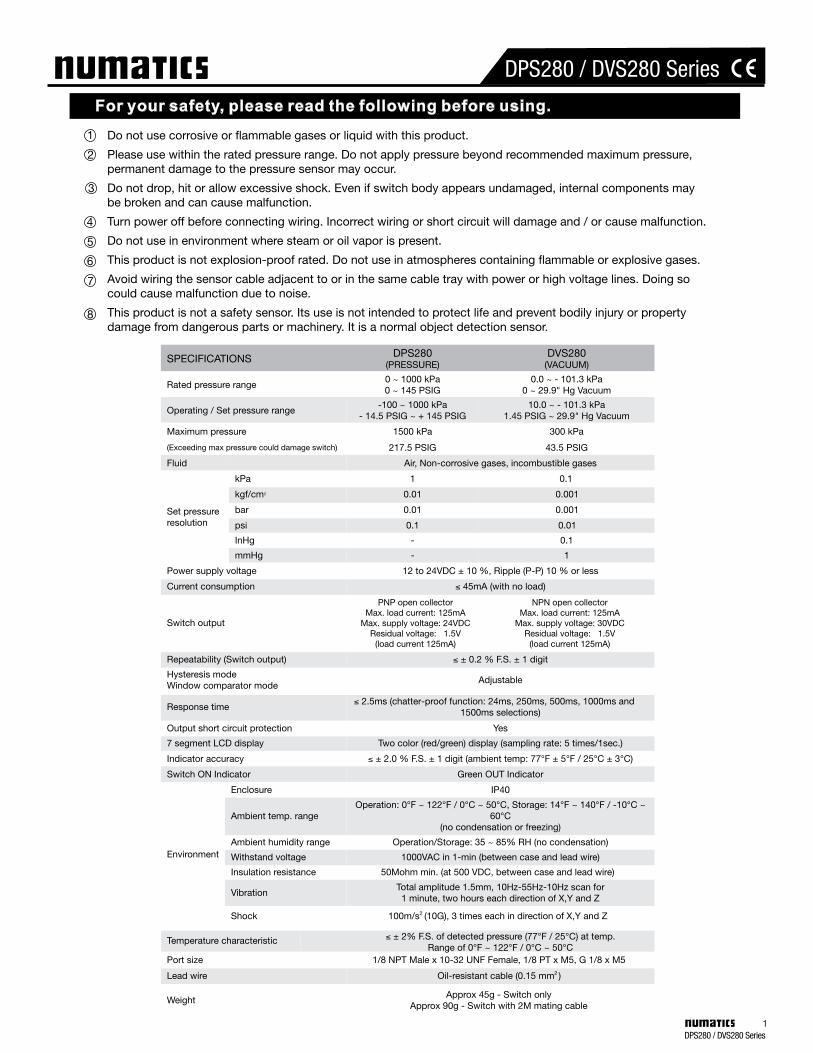
SETTING STEPS
INITIAL SETTING MODE
Sensing Mode
Sensing Mode
Sensing Mode
Unit Setting
UnitsDisplay ColorOperation ModeOutput TypeResponse TimeManual / Auto Setting
Initial Setting Pressure Setting
Display Color Setting
Output Type Setting
Response Time Setting
Manual / Auto Setting
Operation Mode Setting
Zero Calibration Sensing Mode
P_1 or n_1
P_2 or n_2
H
Calibrate switch to zero under atmospheric conditions
Use the or button to select manual / auto setting.
To re-enter sensing mode momentarily press button.
Use the or button to set response time.Sets number of milliseconds between the switch’s reading of the applied pressure value and how quickly the output responds to that change. Prevents output chattering.
See Pressure Setting Modesfor more information
SoG = State “on” Green SoR = State “on” Red
Eg: If SoG is selected. When the Output State is “ON” the large display will be green. If the Output type selected below is “Normally Open” (off) the large display is Red until set point is achieved. At that point the output closes (goes on) and the display will go Green. If the Output type selected below is “Normally Closed” (on) the large display is Green until set point is achieved. At that point the output opens (goes off) and the display will go Red.
Use the or button to set output type.
Normally Opentype
Normally Closedtype
Use the or button to set operating mode.
Use the or button to set display color.
Use the or button to set desired pressure unit.
To enter initial setting mode press and hold button for 3 seconds.
DPS280 / DVS280 Series4

PRESSURE SETTING MODES
KEY LOCK / UNLOCK MODE
Manual Setting Mode
Auto Setting Mode - Hysteresis Mode Only
Alternating Display
Alternating Display
Alternating Display
Alternating Display
Alternating Display
Sensing Mode
Sensing Mode
Sensing Mode
Sensing Mode
Sensing Mode
Sensing Mode
Use when desired Pressure and Hysteresis values are known by operator.
The operator can teach the switch a maximum and minimum value used for P(n)1 and H calculations. Pressure (DPS) or Vacuum (DVS) must be applied to the switch for it to learn the two values.
Use when desired Pressure and Hysteresis values are not known.
Calculation of P1 ValueValue “A” = Maximum ValueValue “B” = Minimum ValueValue “H” Calculation Only
NOTES:
{ }
If Output Type “Normally Open” was selected the LCD - alternating display - will be (P_*) or if “Normally Closed” was selected the LCD - alternating display - will be (n_*) during this step.When setting the P1 Hysteresis value or P1 / P2 Window comparator or H Hysteresis values momentarily depressing the up arrow will increase the pressure value by one digit, maintaining the up arrow will rapid increase the value. Conversely, momentarily depressing the down arrow will decrease the pressure value by one digit, maintaining the down arrow will rapid decrease the value.Once the pressure setting step is complete momentarily depress to return to sensing mode or waiting 10 seconds will automatically default to sensing mode.
If Output Type “Normally Open” was selected the LCD display will be (AP 1) or if “Normally Closed” was selected the LCD display will be (An 1) during this step.To exit Auto Setting mode with AP1 displayed, simultaneously pressing and momentarily will put the switch back to the sensing mode. Once P1 and H values are established the switch will default back to Manual Setting mode allowing the operator to adjust P1 and / or H to suit application.
Select auto / manual setting mode during initial set-up.To enter pressure setting mode, momentarily press button from sensing mode.
Indicates switch is in Auto Setting ModePrepare to cycle pressure (vacuum) to switch.
Cycle pressure (vacuum) to the switch multiple times, the switch will memorize the max. value “A” and min value “B” that were applied. Afterwards, press SET once to store the setting and return to the sensing mode.
*1.*2.
3.
*1.*2. 3.
DPS Example:Value “A” = 100 PSIGValue “B” = 80 PSIG
P1 = 100 - 100 - 80 4
P1 = 95 PSIG
H = 100 - 80 2
H = 10 PSIG
Use or to select key lock / unlock mode.To prevent unauthorized or accidental tampering with the switch settings select the “Lock Mode” function. Panel will display “Key symbol” .( )To enter sensing mode momentarily press button.
NOTES:
DPS280 / DVS280 Series5
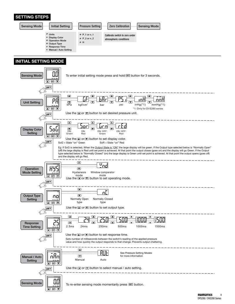
Zero Calibration: Calibrate switch to zero under atmospheric conditions. Press the + buttons at the same time until the “00” is shown. Release the buttons to end zero calibration.
Maximum Applied Pressure Display:Press and hold button 2 seconds to enter the maximum value display mode. Panel will display “Max”. The sensor will now detect and display the maximum pressure value applied, until reset. To reset, press and hold button for 2 seconds to return to the sensing mode.
Minimum Applied Pressure Display:Press and hold button 2 seconds to enter the minimum value display mode. Panel will display “Min”. The sensor will now detect and display the minimum pressure value applied, until reset. To reset, press and hold button for 2 seconds to return to the sensing mode.
ZERO CALIBRATION / THE MAX. & MIN. DISPLAY MODE
FINE ADJUSTMENT MODE
OUTPUT TYPE
Alternating Display
Alternating Display
Sensing Mode
Sensing Mode
It is recommended the Hysteresis value be set greater than the ±0.2% of FS repeatability. If set lower and the applied pressure fluctuates too near the set point, it can cause the digital output to chatter.
(Must have Pressure / Vacuum applied to adjust.)
Pressure (DPS280) Vacuum (DVS280)
Pressure (DPS280) Vacuum (DVS280) Pressure (DPS280) Vacuum (DVS280)
Pressure (DPS280) Vacuum (DVS280)
Current displayed value
DPS280 : When display unit is in “PSI”, setting resolution is 0.2 PSI.DVS280 : When display unit is in “PSI”, setting resolution is 0.02 PSI.
In the pressure setting mode within the available set pressure range, using selected units the operator has preset the P(n)1 and/or {P(n)1 / P(n)2} and a Hysteresis (H) value.Hysteresis mode: (N.O. example) On ascending pressure the digital output will go on value at P1and go off when the pressure drops below P1 by the H value selected.Window comparator mode: (N.O. example) On ascending pressure the digital output will go on at P1 and go off at P2. On descending pressure it will go on again when pressure drops below P2 by the H Value going off again when pressure drops below P1 by the H value.
From initial settings, digital output is selected either “Normally Open” or “Normally Closed”.
Normally Open mode
Normally Closed mode Normally Closed mode
Normally Open mode
To enter fine adjustment mode simultaneously press and hold + for 3 seconds.
FSEUse or to adjust displayed value.
FSCAdjusted Value Percentage DisplayedOnce complete press to return to sensing mode.This function allows operator to manually adjust output display values on multiple switches with identical applied pressure, therefore providing uniformity of the display values.Displayed values of the sensor can be calibrated or adjusted to within a maximum of ±5% for DPS280 and ±2.5% for DVS280.Use or button to adjust displayed value.
Once completed press to return to sensing mode.
NOTES:
NOTES:
DPS280 / DVS280 Series6


![INDEX [globalelectronics.ge] · 2020. 10. 1. · 10. Service Contact Details 23 6BL001-00. Digital Time Switch Crono Pro Digital Time Switch Astro Pro+ Digital Time Switch Astro Pro](https://img.dokumen.tips/doc/110x75/6139361ea4cdb41a985b8fad/index-2020-10-1-10-service-contact-details-23-6bl001-00-digital-time.jpg)