Embed Size (px)
Citation preview

DOUBLE DUCTED FAN (DDF)
By
Cengiz Camci and Ali Akturk
A technology description document
Turbomachinery Aero-heat Transfer LaboratoryVertical Lift Research Center of Excellence
Department of Aerospace EngineeringThe Pennsylvania State University
September 3, 2010

Abstract
This technical paper describes a novel ducted fan inlet flow conditioningconcept that will significantly improve the performance and controllabilityof V/STOL ‘vertical/short take off take-off and landing” UAVs ‘uninhab-ited aerial vehicles” and many other ducted fan based systems. The newconcept that will significantly reduce the inlet lip separation related perfor-mance penalties in the forward flight zone is named ‘DOUBLE DUCTEDFAN (DDF)”. The current concept uses a secondary stationary duct sys-tem to control ‘inlet lip separation” related momentum deficit at the inletof the fan rotor occurring at elevated forward flight velocities. The DDF isself-adjusting in a wide forward flight velocity range. DDFs corrective aero-dynamic influence becomes more pronounced with increasing flight velocitydue to its inherent design properties. The DDF can also be implemented asa ‘Variable Double Ducted Fan” (VDDF) for a much more effective inlet lipseparation control in a wide range of horizontal flight velocities in UAVs, airvehicles, trains, buses, marine vehicles and any axial flow fan system wherethere is a local zone in which there are strong radial velocity componentsdistorting the inlet flow. Most axial flow fans are designed for an inlet flowwith zero or minimal inlet flow distortion. The DDF concept is proven tobe an effective way of dealing with inlet flow distortions occurring near thelip section of any axial flow fan rotor system.
Contents
1 Introduction 41.1 Upstream Lip Region Flow Physics for
Ducted Fans in Forward Flight . . . . . . . . . . . . . . . . . 51.2 Past Studies of Ducted Fan Aerodynamics in Forward Flight 61.3 Lip Separation at High Angle of Attack . . . . . . . . . . . . 131.4 Adverse Effects of Upstream Lip Separation in Forward Flight 151.5 Patents Related to Ducted Fan Powered Vertical Lift Systems
and Their Operation in Forward Flight . . . . . . . . . . . . . 16
2 Double Ducted Fan (DDF) as a Novel Concept 262.1 Geometric Definition of DDF . . . . . . . . . . . . . . . . . . 272.2 Converging-Diverging Channel in the Duct . . . . . . . . . . 282.3 Various Possible Double Ducted Fan Geometries . . . . . . . 30
3 Method of Analysis used in (DDF) Concept Development 323.1 Radial Equilibrium Based Analysis of Ducted Fan in Hover
and Forward Flight . . . . . . . . . . . . . . . . . . . . . . . . 323.1.1 Computational Model Description . . . . . . . . . . . 323.1.2 Boundary Conditions . . . . . . . . . . . . . . . . . . 333.1.3 Actuator Disk Model . . . . . . . . . . . . . . . . . . . 36
4 DDF Concept Validation 394.1 Reference Ducted Fan Characteristics . . . . . . . . . . . . . 394.2 Air Breathing Character of DDF in Forward Flight . . . . . . 414.3 A Comparative Evaluation of Local Velocity Magnitude, Stream-
lines and Total Pressure for All Three Ducts . . . . . . . . . . 484.3.1 CASE-A Tall (DDF) versus Baseline Duct Results /at
10 m/s and 20 m/s . . . . . . . . . . . . . . . . . . . . 48
1

4.3.2 CASE-B Short (DDF) versus Baseline Duct Resultsat 10 m/s and 20 m/s . . . . . . . . . . . . . . . . . . 53
4.4 Upstream Lip Region Local Flow Improvements in (DDF) . . 574.4.1 Static Pressure Distribution around the Lip Section of
the Baseline Duct . . . . . . . . . . . . . . . . . . . . 584.4.2 Static Pressure Distribution around the Lip section of
the Double Ducted Fan (DDF) . . . . . . . . . . . . . 594.4.3 Skin Friction Distribution around the Leading Edge
of the Duct . . . . . . . . . . . . . . . . . . . . . . . . 60
5 Conclusions 62
Bibliography 65
2
Nomenclature
β1 Blade inlet angle (deg)β2 Blade exit angle (deg)c Chord length (m)c1 Rotor inlet absolute velocity (m/s)c2 Rotor exit absolute velocity (m/s)cθ Tangential (swirl) component of the velocity (m/s)cx Axial component of the velocity (m/s)D Overall diameter of the baseline ducted fan (m)h Rotor blade height (Rotor tip radius - Rotor hub radius)(m)p Static pressure (pa)ρ Density (kg/m3)ω Rotational speed (radian/s)r Radial distance measured from origin (m)t Rotor tip clearance (m)w1 Rotor inlet relative velocity (m/s)w2 Rotor exit relative velocity (m/s)X Axial coordinate measured from the inlet plane of the standard
duct (m)x x = X/c , non-dimensional axial distance
3

Chapter 1
Introduction
Although there is a strong interest in V/STOL UAV community to effec-tively deal with the upstream lip separation problem of ducted fans, theinlet flow distortion problem is common to many present day fan rotors ina wide variety of applications. The current conceptual design study clearlyshows that the DDF approach is applicable to any axial flow fan unit inwhich there is an inlet flow distortion mainly because the inlet flow direc-tion is not well aligned with the axis of rotation of the axial fan system. Afew other examples that will easily benefit from the DDF concept describedin this document are the cooling fans that are horizontally mounted at theroof of electric/diesel train locomotive propulsion cabins, air conditioningfans frequently installed at the roofs of passenger buses and cooling/utilityfans that are flush mounted to external surfaces in marine vehicles.
Current approach for proving concept validity: A conventionalbaseline duct without any lip separation control feature is compared to twodifferent double ducted fans named DDF-A and DDF-B via 3D, viscousand turbulent computational flow analysis. Both hover and forward flightconditions are considered. Significant relative improvements from DDF-Aand DDF-B are in the areas of vertical force (thrust) enhancement, nose-uppitching moment control and recovery of mass flow rate in a wide horizon-tal flight range. The results show a major reduction of highly 3D and re-circulatory inlet lip separation zone when the DDF concept is implemented.The improved uniformity of fan exit flow and reduced differentials betweenthe leading side and trailing side are obvious performance enhancing fea-tures of the novel concept. The local details of the flow near the entrancearea of the leading side of the ducted fan are explained via detailed static
4

pressure distributions and skin friction coefficients obtained from 3D vis-cous and turbulent flow analysis including a simulated rotor in the duct.The current rotor flow energy addition simulation is via a radial equilibriumanalysis which is a highly time efficient approach implemented into a RANSbased flow model.
1.1 Upstream Lip Region Flow Physics forDucted Fans in Forward Flight
Ducted fan systems horizontally moving at 90o angle of attack all inherentlyhave an inlet flow direction that significantly deviates from the axis of therotation. The inlet flow distortion near the leading side of all of these fan in-lets becomes more problematic with increasing vehicle speed. The inlet flowdistortion passing through a typical axial flow fan rotor becomes increas-ingly detrimental with elevated forward flight velocity. The lip separationoccurring on the inner side of the lip section severely limits the lift gener-ation and controllability of V/STOL UAVs. In general, the leading side ofthe fan near the lip separation zone breathes poorly when compared to thetrailing side of the ducted fan. The trailing side total pressure is usuallymuch higher than the total pressure observed near the leading side at theexit of the rotor. The flow near the leading side is adversely influenced bya separated flow zone that is characterized as highly re-circulatory, low mo-mentum, unsteady and turbulent.
Conventional ducted fan systems also have a tip clearance loss that isproportional with the effective tip gap size inherent to each design. Thespecific shape of the tip platform and the surface properties and arrange-ment designed onto the casing surface also influences the magnitude of tipclearance loss. This aerodynamic deficiency is measured as a significant totalpressure loss near the tip at the exit of the rotor all around the circumferencewhen the vehicle is only hovering with no horizontal flight. When the vehicletransits into a horizontal flight, the total pressure loss/deficit at the exit ofthe rotor near the leading side is much more significant than “hover only”loss of the ducted fan. In addition to the conventional tip clearance energyloss, the rotor generates additional losses near the leading side, because ofthe re-circulatory low momentum fluid entering into the rotor near the tipsection. This is clearly an off-design condition for an axial flow fan that isdesigned for a reasonably uniform inlet axial velocity profile in the spanwise
5

direction. The immediate results of any inlet flow distortion entering intoan axial fan rotor in horizontal flight are the loss of rotor’s energy additioncapability to the fluid near the leading side, an imbalance of the local massflow rate between the leading side and trailing side, an imbalance of thetotal pressure resulting at the rotor exit between the leading side and trail-ing side, a significant loss of lifting ability due to highly non-axisymmetricand unnecessarily 3D fan exit jet flow, unwanted nose-up pitching momentgeneration because the local static distributions imposed on the duct innersurfaces.
1.2 Past Studies of Ducted Fan Aerodynamics inForward Flight
The viscous flow characteristics of the ducted fan are complex. These ve-hicles need to be capable of flight in a broad range of atmospheric con-ditions, including the complex turbulent flow fields around buildings andtrees. When a V/STOL ducted fan is in horizontal flight, because of therelative inlet flow dominantly parallel to its inlet plane, problems relatedto flow separation at the leading edge duct lip are encountered. When theV/STOL vehicle is in perfect horizontal flight the angle between the relativeinlet flow direction and the axis of rotation of the rotor is about 90o. Thisangle is usually termed as “angle of attack”. At high angle of attack, theinlet flow separation leads to problems within the duct and may result in ahigh nose-up pitching moment as the forward speed is increased. Therefore,measuring and predicting the mean flow characteristics of ducted fans iscrucial to understand the problems related to reliable and controllable hori-zontal flights. Numerous studies have been undertaken in order to quantifythe flow field characteristics around ducted fans. The operation of an axialflow fan with strong inlet flow distortion severely affects the performance ofthe rotor especially near the tip region of the blades.
Experimental investigation has been the major approach to study themean flow characteristics of the conventional ducted fan. Abrego and Bu-laga [1] performed wind tunnel tests to determine the performance charac-teristics of ducted fans for axial and forward flight conditions. Their studyresulted in showing important effect of exit vane flap deflection and flapchord length on providing side force.
6

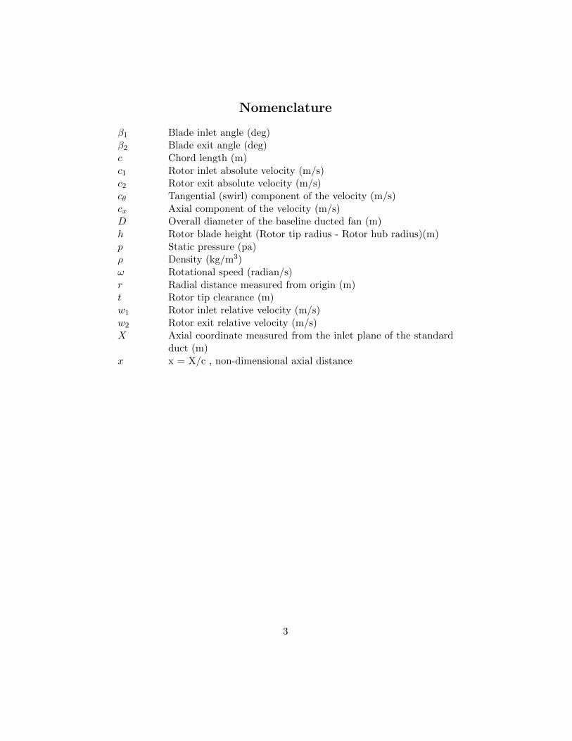
Martin and Tung [2] tested a ducted fan V/STOL UAV with a 10-inchdiameter rotor. They measured aerodynamic loads on the vehicle for dif-ferent angles of attack( from 0o to 110o ) in hover and different crosswindvelocities (41 knots, 70 ft/s). Both models were tested with fixed-pitch pro-pellers of varying diameters, to test tip clearances from 1% to 4% (basedon rotor tip radius). They also included hot-wire velocity surveys at innerand outer surface of the duct and across the downstream wake emphasizingthe effect of tip gap on the thrust force produced. In addition, their studyshowed the effect of leading edge radius of the duct on the stall performanceand stability of the vehicle. Figure 1.1 illustrates thrust of the system isdecreasing with increasing tip gap height. Their results also showed that forlower rotational speeds open rotor thrust was higher than ducted fan thrust.They explained this by pointing out the increase in viscous losses inside theduct for low rotational speed operations. Figure 1.1b shows their oil flowvisualization study. Thay have shown interaction of duct boundary layerand tip leakage vortex in their study.
Fleming et al.[3] published the results of a study on the performanceperformance of ducted fan inlet lips and exit vanes, in crosswind . Beside theexperimental study they performed in wind tunnel, they also run computa-tional analysis on Vertical Take-Off and Landing Unmanned Aerial Vehicles(VTOL UAV) ducted fans. Beside conventional control vanes, they testedseven different auxiliary control devices in crosswind. These control devicesare an internal duct vane and thrust reverser that are adapted from Moller’scontrol device [4], a “duct deflector” on the windward side of the internalduct wall; a trailing edge flap on the leeward side of the duct, which in-creases the effective camber of the duct profile; an inlet lip spoiler at thewindward side; “leading edge slat” on the leeward side of the inlet; and lipflow control using normal and tangential flow blowing at the lip. Figure 1.3shows control devices tested by Fleming et al.[3]. They have tested their10 inch diameter ducted fan model in hover and crosswind up to 50 ft/s.They have selected “lip flow control by blowing”, “internal duct vane” and“internal duct deflector with bleed” as efficiently performing devices. Atlow crosswind speeds, control vanes performed better than other methods.However, as the crosswind speed increased, the authors observed that thecontrol vanes are stalled.
Graf et al.[5, 6] improved ducted fan forward flight performance with arecently designed leading edge geometry, which became a significant factorin offsetting the effects of adverse aerodynamic characteristics for elevated
7
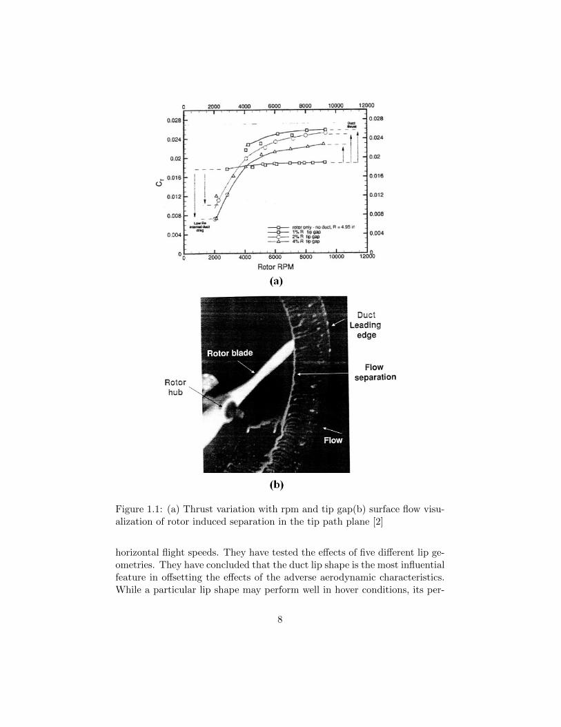
Figure 1.1: (a) Thrust variation with rpm and tip gap(b) surface flow visu-alization of rotor induced separation in the tip path plane [2]
horizontal flight speeds. They have tested the effects of five different lip ge-ometries. They have concluded that the duct lip shape is the most influentialfeature in offsetting the effects of the adverse aerodynamic characteristics.While a particular lip shape may perform well in hover conditions, its per-
8

Figure 1.2: Control devices tested by Fleming et al.[3]
formance in crosswind conditions can be inferior to other designs.
Lazareff [7] investigated the aerodynamic performance of ducted fans byusing both theoretical and experimental methods. The flight performancecalculations are also shown in that study. The difference between ductedfans and free propellers is extensively discussed.
Weelden and Smith tried investigated ducted fan aerothermodynamicperformance by utilizing systematic component build-up approach [8]. Theyemphasized the importance of the inlet and diffuser in performance of ductedfans.
9
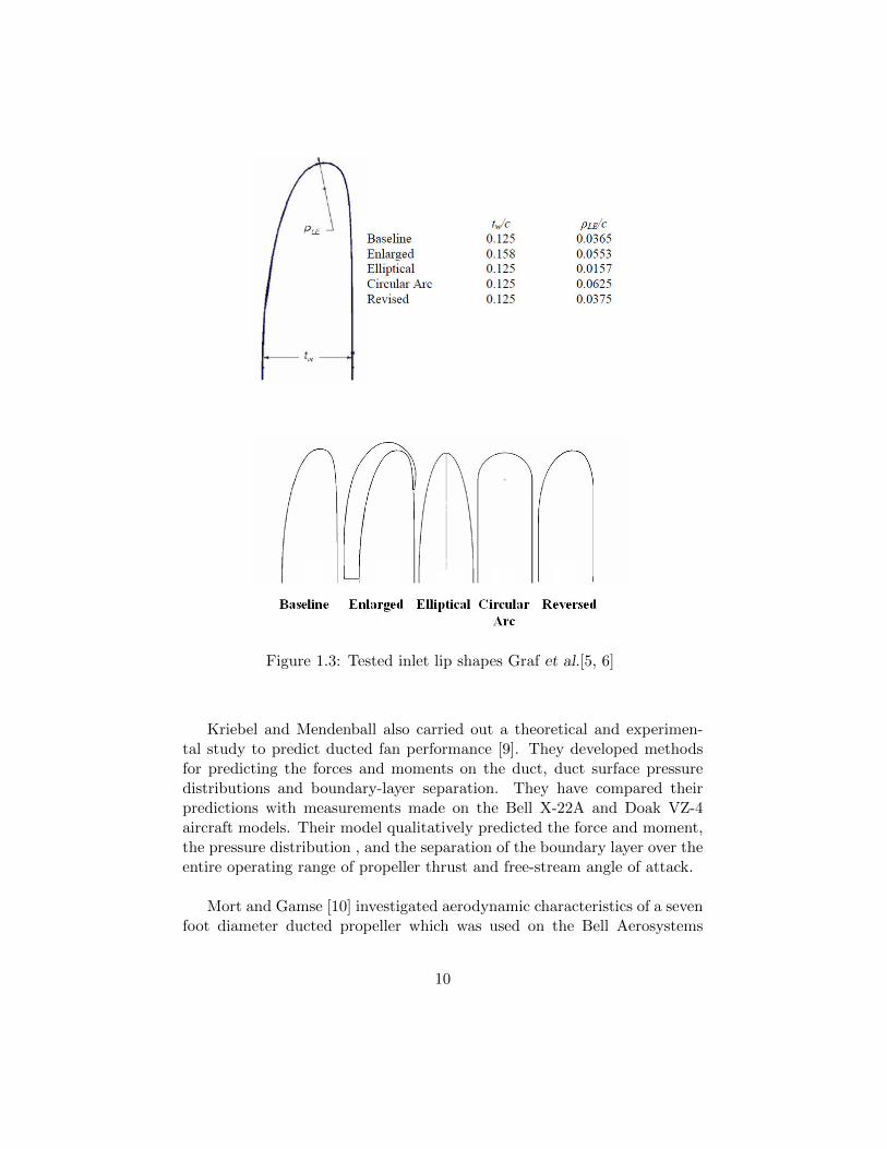
Figure 1.3: Tested inlet lip shapes Graf et al.[5, 6]
Kriebel and Mendenball also carried out a theoretical and experimen-tal study to predict ducted fan performance [9]. They developed methodsfor predicting the forces and moments on the duct, duct surface pressuredistributions and boundary-layer separation. They have compared theirpredictions with measurements made on the Bell X-22A and Doak VZ-4aircraft models. Their model qualitatively predicted the force and moment,the pressure distribution , and the separation of the boundary layer over theentire operating range of propeller thrust and free-stream angle of attack.
Mort and Gamse [10] investigated aerodynamic characteristics of a sevenfoot diameter ducted propeller which was used on the Bell Aerosystems
10

Company X-22A airplane. They reported aerodynamic characteristics forvariations of power, free-stream velocity, blade angle, and duct angle of at-tack. Stall of both the upstream and downstream duct lips of this seven footdiameter ducted fan was examined as a function of angle of attack. It wasfound that the onset of separation on the upstream lip will be encountered;however, complete separation on this lip will be encountered only duringconditions of low power and high duct angle of attack.
Mort and Yaggy [11, 12] performed hover and forward flight tests on afour foot diameter wing-tip mounted ducted fan that is used on Doak VZ-4-DA. Performance characteristics for the ducted fan were reported. Theyemphasized that pitching moment was rapidly changed and required powerwas increased due to separation, which occurred at windward side duct lip.They also reported that ducted fan supported by a fixed wing required lesspower in comparison to free flying ducted fan.
Weir has a study on experimental and theoretical performance of ductedfans with different inlet lip configurations [13]. In this study the momentsand forces affecting the ducted fan were measured for different configura-tions. The design of exit vanes and fan rotor is also mentioned in the paper.The effect of the inlet lip radius on the lift and pitching moment combinedwith a diffuser is carefully investigated. As the inlet lip radius is increasedthe lift force of the ducted fan is also increased slightly. Adding a diffuser tothe system has also positive effects on the lift. However, they both produceincreased pitching moments.
Pereira performed an experimental study on the effects of various shroudprofile shapes on the performance of MAV-scale shrouded rotors [14]. Sev-enteen ducted fan models with a nominal rotor diameter of 16 cm (6.3 in)and various values of diffuser expansion angle, diffuser length, inlet lip ra-dius and blade tip clearance were tested at various rotor collective angles.Tests performed for open rotor and a single shrouded-rotor model at a singlecollective in translational flight, at angles of attack from 0o (axial flow) to90o (edgewise flow), and at various advance ratios are reported.
Martin and Boxwell [15] tested two ducted fan models that were designedto effectively eliminate the tip leakage. Both models were derived from thebaseline (10-inch inner-diameter shroud) which is explained in their previousstudy [2]. In their fist design, they have created a notch and fit the propellerinside the notch. In their second design, a rearward-facing step was cut into
11

the inner shroud. Their designs are shown in Figure 1.4. The computa-tional analysis resulted in an increase in inlet lip suction and an increase inperformance. However, the experimental thrust and power measurements,showed no difference in performance of these designs when compared to theirbaseline duct.
Figure 1.4: Notched and stepped duct designs [15]
12

In addition to experimental studies, the ducted fan design and perfor-mance analyses were widely performed by using computational flow model-ing. Lind et al.[16] carried out a computational study using a panel method.They compared their results to the experimental results from Martin andTung [2]. He and Xin [17] developed the ducted fan models based on a non-uniform and unsteady ring vortex formulation. A numerical study in axialand horizontal flight conditions was conducted and validated with measureddata. Chang et al.[18] developed an accurate grid generation methodologyknown as “the curve adaptive option” to model several industrial ductedfans. An axisymmetric, incompressible Navier-Stokes solver was imple-mented to calculate the flow field of a duct fan. The computational resultsagreed well with available wind tunnel data. Ahn et al.[19] applied a compu-tational method to their ducted fan system to identify the design parameterswhich affect its performance. Their ducted fan system was designed by us-ing the stream-surface based axisymmetric analysis which considered overallphysical characteristics and design parameters of the system. Ko et al.[20]developed a computer code aimed at the preliminary design of a ducted fansystem. This code was validated using data from many wind tunnel andflight tests. It was also extensively used in the design of commercial ductedfans. Recently, Zhao and Bil [21] proposed a CFD simulation to design andanalyze an aerodynamic model of a ducted fan UAV in preliminary designphase with different speeds and angles of attacks.
1.3 Lip Separation at High Angle of Attack
The new concept named “Double-Ducted Fan (DDF)” is based on a veryeffective fluid mechanics scheme of reducing and controlling the upstreamlip separation in a ducted fan operating at high angle of attack. Earlyresearch results clearly demonstrating the limits of onset of upstream lipseparation as a function of angle of attack are summarized in Figure 1.5.A full scale duplicate of the V/STOL ducted propeller used on the BellAerosystems Co. X-22A airplane was tested in Ames Research center byMort and Gamse [11, 12]. Stall of both the upstream and downstream ductlips of this seven foot diameter ducted fan was examined in function of angleof attack. The angle of attack of the ducted fan is the angle between theapproaching flow direction and the axis of rotation of the rotor. It wasfound that the onset of separation on the upstream lip will be encountered;however, complete separation on this lip will be encountered only during
13

conditions of low power and high duct angle of attack corresponding to highrates of descent.
Figure 1.5: Upstream duct lip stall in function of angle of attack for X-22Aducted fan [11, 12]
Tests of a wing-tip-mounted 4-foot-diameter ducted fan were performedfor a limited range of operating conditions by Mort and Yaggy [10]. At largeduct angles of attack, the inside of the upstream duct lip stalled causing arapid change in the duct pitching moments and accompanying increase inthe power required. At low horizontal velocities this lip stall would prob-ably limit the rate of descent of a vehicle with a wing tip mounted ductedfan. The wind tunnel test results shown in Figure 1.5 are highly relevantin demonstrating the beneficial aerodynamic characteristics of the doubleducted fan DDF concept presented in this section.
Although, the reference ducted fan rotor had a tip clearance of t/h=5.8%, the tip clearance influence on the rotor downstream flow was knowinglyexcluded from the current 3D computational flow effort. The present simpli-fied rotor flow model does not include tip clearance effects since the currenteffort is focused on the accurate simulation of the lip separation flow during
14

forward flight of the vehicle. A radial equilibrium theory based rotor diskwithout a tip gap was chosen as a simplified and time efficient rotor modelin this section.
1.4 Adverse Effects of Upstream Lip Separationin Forward Flight
At high angle of attack, the onset separation at the upstream duct lip isaccompanied by the formation of a separation bubble. Existence of a signif-icant separation bubble severely distorts inlet flow of the fan rotor especiallynear the leading side and in the tip clearance region. Distorted inlet flowcauses an asymmetric loading of the ducted fan which increases the powerrequired for level un-accelerated flight and noise level. The immediate re-sults of operating a ducted fan in horizontal flight regime especially at highangle of attack are as follows:
• Increased aerodynamic losses and temporal instability of the fan rotorflow when “inlet flow distortion” from “the lip separation area” findsits way into the tip clearance gap leading to the loss of “energy additioncapability” of the rotor.
• Reduced thrust generation from the upstream side of the duct due tothe rotor breathing low-momentum and re-circulatory, turbulent flow.
• A severe imbalance of the duct inner static pressure field resulting fromlow momentum fluid entering into the rotor on the leading side andhigh momentum fluid unnecessarily energized near the trailing side ofthe rotor.
• A measurable increase in power demand and fuel consumption whenthe lip separation occurs to keep up with a given operational task.
• Lip separation and its interaction with the tip gap flow requires amuch more complex vehicle control system because of the severe non-uniformity of the exit jet in circumferential direction and excessivenose-up pitching moment generation.
• At low horizontal speeds a severe limitation in the rate of descentand vehicle controllability may occur because of more pronounced lip
15

separation. Low power requirement of a typical descent results in alower disk loading and more pronounced lip separation.
• Excessive noise and vibration from the rotor working with a significantinlet flow distortion.
• Very complex unsteady interactions of duct exit flow with control sur-faces.
1.5 Patents Related to Ducted Fan Powered Ver-tical Lift Systems and Their Operation in For-ward Flight
Ducted fans are very popular among the vertical lift systems. They havebeen used in many conceptually designed VTOL vehicles. Patents relatedto ducted fan powered vertical take-off vehicles are described in this section.
Dorman, 2,951,661 (1960): Four ducted fan/propeller units locatedon each quadrant of a square vehicle footprint are used as lift generatingcomponents to be used in a heavier than air VTOL vehicle, Dorman [22].The axis of rotation of each ducted fan unit is normal to the horizontal plane.This is one of the earliest presentations of using ducted fans in VTOL vehicleapplications. This patent does not include any discussion on lip separationproblem in forward flight regime.
Bright, 2,968,453 (1961): Bright [23] presented an early form of thetwo well known and more recent vehicle concepts from Yoeli [24] (Xhawk)and Piasecki [25] (Piasecki Air Jeep). Two ducted fans are embedded intoa relatively flat fuselage with two fixed wings extending from the sides ofthe fuselage. An extensive adjustable shutter based exit flow control systemwas used to control the side force, yaw, pitch and roll motions of the vehicle.Inlet flow to the ducted fan units were not treated using louvers, vanes orshutters of any kind. Leading side lip separation problem is not mentioned.
Fletcher, 2,988,301 (1961): A V/STOL aircraft concept using acounter rotating ducted fan embedded in a flat airfoil shaped fuselage waspresented by Fletcher [26] in an effort to transist a V/STOL aircraft to pro-pel itself in high speed flight. Forward flight related propulsive force wasobtained from a conventional propeller mounted on the aft section of the ve-hicle. This vehicle has a provision to close the inlet surface of the fan rotor
16
system completely in forward flight only relying on the lift force generatedby the airfoil shaped fuselage and the propulsive force of the aft propeller.Inlet lip separation problem inherent to most ducted fan based systems ofthis type was never mentioned in this reference.
Piasecki, 3,184,183 (1965): This patent[25] explains Frank Piasecki’swell publicized “Air Jeep” concept shown in Figure 1.6 that uses two counterrotating lifting rotors in a tandem ducted fan arrangement. This approachwas unique because of a novel control linkage for its ducted vertical liftrotors for adjusting cyclic pitch and collective pitch of the rotating blades.The propulsive force in Piasecki’s approach [25] was obtained by cyclic andcollective control of the rotor blades operating in a ducted fan arrangement.The rotor performance variation affected the local flow features near theleading side lip section of the duct. A significant component in this patentwas the use of a movable spoiler in the inner part of the leading side lipof the duct. A movable spoiler that had a serrated edge is used to controllocal flow characteristics over the lip radius in an effort to reduce the drag(aerodynamic loss) generated over this area, especially in horizontal flight.This is one of the first known attempts to correct the inlet lip separationproblem using a movable spoiler located over an arc length of the inlet lip.However, the specific corrective action taken for the lip separation problemis based on adjustable inlet boundary layer tripping.
Boyd, 3,159,224 (1970): This invention from Boyd [27] focused ona circular aircraft using an outer circumferential fan type ducted rotormounted on air bearings. The ducted rotor was driven by outboard gasgenerators. This system used adjustable radial stator blades above the ro-tor. The stator blades were differentially adjustable in the forward andrearward quadrants to control the attitude of the aircraft with respect toits pitch axis. The stator blades in the left and right side quadrants couldcontrol the attitude of the aircraft with respect to its roll axis. The headingof the aircraft was controlled by means of a set of radial stator blades atthe exit of the rotor. This approach only deals with the attitude control ofa circular V/STOL vehicle and there is no treatment in this document inregard to possible inlet lip separation problem.
Wen 4,049,218 (1977): Wen et al.[28] described a VTOL aircraft usinga centrifugal impeller generating a fan exit jet that can attain high exit jetvelocities for effective vertical take off. His concept is shown in Figure 1.7.The centrifugal impeller output is passed through a diffuser section and
17
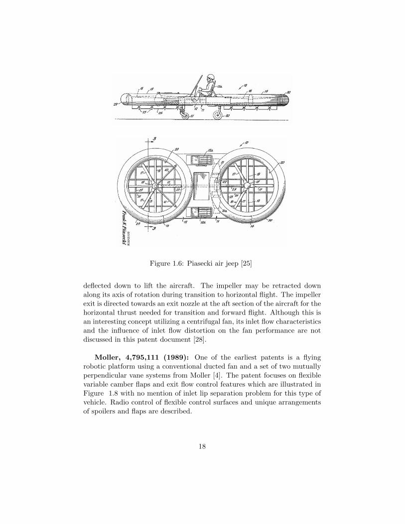
Figure 1.6: Piasecki air jeep [25]
deflected down to lift the aircraft. The impeller may be retracted downalong its axis of rotation during transition to horizontal flight. The impellerexit is directed towards an exit nozzle at the aft section of the aircraft for thehorizontal thrust needed for transition and forward flight. Although this isan interesting concept utilizing a centrifugal fan, its inlet flow characteristicsand the influence of inlet flow distortion on the fan performance are notdiscussed in this patent document [28].
Moller, 4,795,111 (1989): One of the earliest patents is a flyingrobotic platform using a conventional ducted fan and a set of two mutuallyperpendicular vane systems from Moller [4]. The patent focuses on flexiblevariable camber flaps and exit flow control features which are illustrated inFigure 1.8 with no mention of inlet lip separation problem for this type ofvehicle. Radio control of flexible control surfaces and unique arrangementsof spoilers and flaps are described.
18

Figure 1.7: Side view and a partial section of a VTOL design by Wen etal.[28]
Figure 1.8: Control vanes, spoilers and thrust reverser designs of Moller [4]
Cycon et al.5,152,478 (1992): Sikorsky Cypher [29] shown in Figure1.9 was an uninhabited aerial vehicle that included a toroidal fuselage andtwo co-axial counter-rotating rotors in a ducted fan arrangement. The tworotors provided both the vertical and horizontal thrust needed in hover andforward flight. A vertical take off required a completely horizontal opera-tion for obtaining a vertical down wash of the rotors to obtain the necessary
19

lift for the aircraft. Transition to forward flight was achieved by tilting thefuselage in a “Nose-down” mode to generate a horizontal thrust component.In the forward flight mode, the rotor inlet flow was usually altered such thatthe leading side lip had significant flow separation and the trailing side of theduct had incoming flow impinging on the inner side of the shroud creatinga drag penalty. The inlet nose separation, impingement on the aft part ofthe shroud and the interaction of this inlet flow distortion with the rotorsresulted in significant pitch-up moment generation on this vehicle. Cypheris one of the few VTOL vehicles that used cyclic pitch of the rotors in en-countering the nose-up pitch pitching moment generation. Although thiscontrol feature unique to Cypher reduced the excessive pitching moment,it required considerable amount of power and did not eliminate the draggeneration on the trailing side of the shroud.
Figure 1.9: Sikorsky Cypher I with two co-axial counter-rotating rotors ina ducted fan arrangement [29]
Moffit et al.5,150,857 (1992): Another solution in reducing the pitch-ing moment was the use of an optimized toroidal fuselage airfoil profile,Moffit et al.[30] The cross sectional geometry of the toroidal airfoil was opti-mized such that the increasing pitching up moment with increased forwardflight velocity was measurably reduced. The pitching up moment reduction
20

was very effective from 20 knots vehicle speed up to 70 knots, which wasthe maximum flight velocity tested in a wind tunnel. The lift of the shroudwas also effectively increased via this toroidal fuselage airfoil optimization.While incorporation of an optimized toroidal airfoil was a viable option, tocounteract nose-up pitching moments, there was a manufacturing penaltyassociated with the new profile and an adverse effect on higher speed flightcharacteristics.
Flemming et al.5,419,513 (1995): Adding a highly cambered fixedwing to a toroidal fuselage was a significant method of dealing with exces-sive pitch-up moment generation encountered in forward flight of Cypher.Flemming et al.[31] used a high-lift high-camber airfoil with a center of liftlocated significantly aft of the quarter chord line of the airfoil. The sym-metrically mounted fixed wings had centers of lift located aftwardly of thefuselage axis of the toroidal fuselage in forward flight mode such that thefixed wings generate a nose-down pitching moment to counteract the nose-up pitching moment originating from the separated air flow over the leadingside lip of the duct. The fixed wings were mounted in a fixed arrangementat a predetermined angle of incidence although a variable incidence systemfor the fixed wing is possible.
Swinson et al.5,890,441 (1999): An autonomously controlled, gyro-scopically stabilized, horizontal and vertical take off and landing (HOVTOL)vehicle using vertical lift devices was presented by Swinson et al.[32]. Al-though this vehicle had similarities to most of the systems reviewed in thissection, the specific patent focused on the autonomous controllability of thevehicle rather than the aerodynamic features and inlet lip separation prob-lem.
Cycon et al.6,170,778 (January 2001): A new method of reduc-ing nose-up pitching moment during forward flight on a ducted uninhabitedaerial vehicle was presented by Cycon et al.[33] The vehicle shown in Figure1.10 consisted of a doughnut shaped fuselage that had a counter rotatingducted fan with fixed wings attached to it for improved forward flight char-acteristics. The system also had a shrouded pusher propeller for horizontalthrust in forward flight. Cycon et al.[33] used the method of adding highlift cambered airfoils to the sides of the toroidal fuselage of Cypher to coun-teract the nose-up moments generated in forward flight. The specific fixedwings also had flaperons for the precise adjustments of lift forces needed atdifferent horizontal flight regimes. This system also had directional turning
21

vanes at the aft section of the pusher propeller to deflect propeller thrustdownward, creating additional lift to counteract nose up moments in highspeed forward flight. They also noted that locating the pusher prop assem-bly aft of the duct reduced drag on the aircraft. The pusher prop has beenfound to draw turbulent air over the duct that would otherwise flow intothe duct. Cycon [33] also suggested an excellent way of concealing the rotorsystem in high speed flight. Conventional systems used relatively heavy andcomplex covers to block the air entrance to the ducted fan in high speedforward flight. Operating the counter rotating rotors at zero pitch resultedin a virtual cover system impeding the airflow into the duct. By blocking theflow and forcing it to flow over and under the aircraft, drag was effectivelyreduced without the weight and complexity of rigid covers.
Cycon et al.6,270,038 (August 2001): In addition to the flaperonsin the fixed wings and the directional turning vanes in the propeller shroudexit, this invention [34] reported one or more deflectors mounted to the bot-tom of the fuselage for further drag reduction. The deflectors effectivelycontrolled airflow into the duct from the bottom of the fuselage during for-ward flight. These deflectors were passive and required no actuation. Theyopened and closed automatically based on the airflow through and over theduct. The combination of zero pitch counter rotating rotors and passiveflow deflectors on the bottom of the duct reduced the drag component onthe aircraft between the open rotor and completely covered duct by about80 %.
Moller, 6,450,445 (2002): A remotely controlled flying platform or arobotic platform was previously presented by Moller [4]. This concept morerecently presented by Moller [35] used a counter rotating set of axial rotorsin a ducted fan arrangement. Although an extensive set of fan exit flow con-trol surfaces were used in this system, the inlet lip separation problem wasnot mentioned. The specific exit flow control surfaces are named “multipleadjustable air deflector assemblies” controlled by two servo motors. Theinvention focuses on the actuation of the individual air deflectors via servomechanisms.
Yoeli, 6,464,166 (2002): This approach introduced by Yoeli [24] usesa plurality of parallel spaced vanes located in front of and behind the ductedfan rotor of a VTOL vehicle illustrated in Figure 1.11. The vanes are se-lectively pivotal to produce a desired horizontal force component to the lift
22
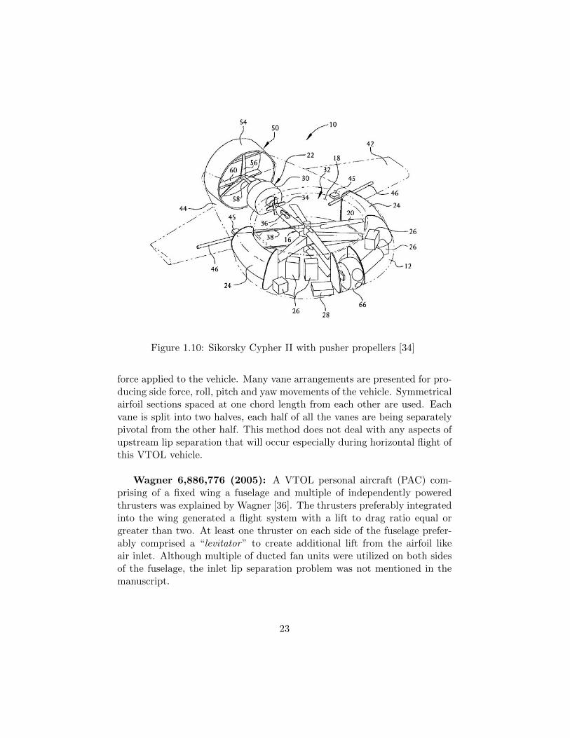
Figure 1.10: Sikorsky Cypher II with pusher propellers [34]
force applied to the vehicle. Many vane arrangements are presented for pro-ducing side force, roll, pitch and yaw movements of the vehicle. Symmetricalairfoil sections spaced at one chord length from each other are used. Eachvane is split into two halves, each half of all the vanes are being separatelypivotal from the other half. This method does not deal with any aspects ofupstream lip separation that will occur especially during horizontal flight ofthis VTOL vehicle.
Wagner 6,886,776 (2005): A VTOL personal aircraft (PAC) com-prising of a fixed wing a fuselage and multiple of independently poweredthrusters was explained by Wagner [36]. The thrusters preferably integratedinto the wing generated a flight system with a lift to drag ratio equal orgreater than two. At least one thruster on each side of the fuselage prefer-ably comprised a “levitator” to create additional lift from the airfoil likeair inlet. Although multiple of ducted fan units were utilized on both sidesof the fuselage, the inlet lip separation problem was not mentioned in themanuscript.
23
Yoeli, 6,883,748 (2005): This invention [37] deals with the use of twoducted fans, four ducted fans and multiple free propellers on VTOL vehi-cle types already discussed by Yoeli in his previous patents. In addition tomany military configurations possible with this vehicle, a hovercraft versionusing a flexible skirt extending below the fuselage is discussed.
Yoeli, 0,034,739 (2007): A ducted fan based VTOL vehicle includinga fuselage having a longitudinal axis and a transverse axis, two counterrotating ducted fan lift producing propellers are described by Yoeli [38] .Many variations are described enabling the vehicle to be used not only asa VTOL vehicle, but also as a multi function utility vehicle. An unmannedversion of the same vehicle is also described. Although an extensive use ofinlet louvers and exit control surfaces are in place, there is no mention ofan inlet lip separation control system near the leading side of the fans. Thespecific approach uses means for enabling the external flow penetrating thewalls of the forward ducted fan for minimizing the momentum drag of thevehicle.
Yoeli, 7,275,712 (2007): This patent [39] described an enhancementof his 2002 concept [24] of parallel spaced vanes located in front of and be-hind the ducted fan rotor of a VTOL vehicle. Additional vane arrangementswere presented for producing side force, roll, pitch and yaw movements ofthe vehicle. The left and right sides of the circular area at the rotor inlet andexit had parallel spaced vanes that were not in the direction of horizontalflight. The angle between the vanes and the flight direction was about 45degrees for this specific patent. This patent did not have any description ofinlet lip separation problem.
24

Figure 1.11: A ducted fan based VTOL vehicle including a fuselage havinga longitudinal axis and a transverse axis, two counter rotating ducted fanlift producing propellers [24, 37–39]
25

Chapter 2
Double Ducted Fan (DDF)as a Novel Concept
A novel ducted fan concept as a significant improvement over a standardducted fan is explained in Figure 2.1. The poor forward flight characteris-tics of the reference duct as shown in Figure 2.1a are effectively improvedwith the “Double Ducted Fan” concept as presented in Figure 2.1b. A typ-ical deficiency of a standard ducted fan is mainly related to the forward lipseparation increasingly occurring when the forward flight velocity is gradu-ally increased as shown in the streamline patterns of Figure 2.1a.
Figure 2.1: Separated flow near the forward lip section of a standard ductedfan (left) and the flow improvements from the novel concept Double DuctedFan (DDF) at 9000 rpm,colored by the magnitude of velocity
The inlet flow near the leading side of the standard duct is highly sepa-rated, low-momentum and turbulent. The apparent flow imbalance between
26

the leading side and trailing side of the standard ducted fan as shown inFigure 2.1a is also called an “inlet-flow-distortion”. Flow simulations inFigure 2.1a show that the rotor barely breathes at the inlet section of theleading side although the trailing side passes a significant amount of flow.This flow imbalance amplified during the rotor “energy adding process” isone of the reasons of significant nose-up pitching moment generation. Figure2.1b also presents the Double Ducted Fan (DDF) flow simulations indicatingthe effective inlet flow distortion reduction due to the unique aerodynamicproperties of the (DDF) system. The upstream lip separation near the lead-ing side is almost eliminated resulting in a more balanced rotor exit flowfield between the leading side and the trailing side. More detailed descrip-tions of the local flow field improvements resulting from the novel DoubleDucted Fan (DDF) concept are discussed in the final part of this document.Although there may be many other potentially beneficial variations of theDouble Ducted Fan concept, only the specific (DDF) form defined in Figure2.1b will be explained in detail in the preceding sections.
2.1 Geometric Definition of DDF
The DDF concept uses a second duct using a lip airfoil shape that has amuch shorter axial chord length than that of the standard duct. The keyparameter in obtaining an effective DDF arrangement is the size of the lipdiameter DL of the standard ducted fan. The second duct airfoil that isrelatively cambered has a leading edge diameter set to 0.66 DL as explainedin Figure 2.2b. The angular orientation and axial position of the second ductairfoil is extremely important in achieving a good level of flow improvementnear the leading side of the rotor. The leading edge circle of the secondduct airfoil is slightly shifted up in the vertical direction for proper inletlip separation control. The vertical distance between the duct inlet planetouching the standard duct and the plane touching the second duct is about0.33DL as shown in Figure 2.2b. The horizontal distance between thecenters of the leading edge circles of the standard duct and outer duct isabout 4DL. The axial chord of the second duct airfoil is about 5DL. Theseparation distance between the standard duct and second duct is controlledby the recommended throat width of 0.8DL as shown in Figure 2.2b.
27

Figure 2.2: (a)Reference duct airfoil definition in a standard ducted fanarrangement, (b)Double Ducted Fan (DDF) geometry as a novel concept
2.2 Converging-Diverging Channel in the Duct
The second duct and the standard duct forms a converging-diverging chan-nel starting from the trailing edge of the second (outer) duct that is locatedat about X=5DL . The axial position of the throat section is about 0.45cwhere c is the axial chord of the inner duct as shown in Figure 2.2b. Theduct width at the entrance of the converging-diverging duct is DL. The en-trance to the converging-diverging channel is at the trailing edge point of thesecond duct. There is a (vertically up) net flow in the converging-divergingduct of the DDF. This flow is due to increasing dynamic pressure at the en-trance of the converging-diverging duct at X=5DL when the forward flightvelocity is increased. The diverging part of the channel flow between thestandard and outer duct is extremely important in this novel concept, sincethis decelerating flow is instrumental in adjusting the wall static pressuregradient just before the lip section of the leading edge of the standard duct.The self-adjusting dynamic pressure of the inlet flow into the converging-diverging duct is directly proportional with the square of the forward flightvelocity of the vehicle. The converging-diverging duct flow is in vertically updirection near the leading edge of the vehicle. The flow in the intermediatechannel is vertically down when one moves away from the frontal section ofthe vehicle. This flow direction is caused by the relatively low stagnation
28
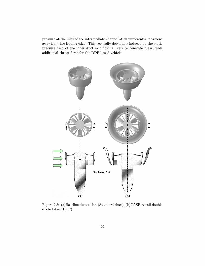
pressure at the inlet of the intermediate channel at circumferential positionsaway from the leading edge. This vertically down flow induced by the staticpressure field of the inner duct exit flow is likely to generate measurableadditional thrust force for the DDF based vehicle.
Figure 2.3: (a)Baseline ducted fan (Standard duct), (b)CASE-A tall doubleducted dan (DDF)
29

Figure 2.4: (a)CASE-B short double ducted fan (b)Eccentric double ductedfan
2.3 Various Possible Double Ducted Fan Geome-tries
The standard duct and three possible variations of the Double Ducted Fan(DDF) concept described in this study are presented in Figures 2.3 and2.4. Three dimensional solid models of the four duct configurations, a hor-
30

izontal cross section and a vertical cross section are included in these figures.
CASE-A as shown in Figure 2.3b is termed as the tall DDF. The tallDDF is able to generate a significantly higher thrust in hover position thanthat of the standard duct containing an identical rotor. However, in for-ward flight, due to the extended axial chord of the outer duct, the nose-uppitching moment generation is also significant in this design. This designhas a throat section located at the trailing edge of the duct airfoils. Sincethe axial chord of the outer duct is longer than that of the inner duct thisdesign may have a drag penalty when compared to the standard ducted fan.
Figure 2.4a shows the most effective Double Ducted Fan (DDF) con-figuration CASE-B since it has the ability to generate a significant amountof thrust when compared to that of the standard ducted fan configuration.Another important characteristic of CASE-B is its ability to operate withoutenhancing the nose-up pitching moment of the vehicle in forward flight. Thisconfiguration was analyzed in great detail mainly because of its combinedability to enhance thrust and reduce nose-up pitching moment in forwardflight without a significant drag increase.
An ECCENTRIC DOUBLE DUCTED FAN (DDF) concept is also shownin Figure 2.4b. This concept requires a movable outer duct in order tocontrol the throat area in the intermediate duct of the vehicle for a highlyoptimized forward flight performance.Variable throat mechanism introducedin this concept provides a greater range of operation in a DDF type vehicleoffering a more accurate lip flow control over a much wider forward flight ve-locity range. Figure 2.4b shows a highly blocked second duct that is properfor very low forward flight velocity. It is required that the throat area is en-larged by moving the outer duct as the forward flight velocity is increased.Although an almost optimal lip separation control can be achieved with aneccentric (DDF), its mechanical complexity and weight penalty is obvious.The outer duct airfoil definition of this concept is the same as CASE-B thatis described in detail in Figure 2.2b.
31
Chapter 3
Method of Analysis used in(DDF) ConceptDevelopment
A three dimensional simulation of the mean flow field around the ducted fanwas performed using a custom developed radial equilibrium based rotor diskmodel implemented into the commercial code Ansys/Fluent. The specificcomputational system solves the Reynolds Averaged Navier-Stokes (RANS)equations using a finite volume method.
3.1 Radial Equilibrium Based Analysis of DuctedFan in Hover and Forward Flight
3.1.1 Computational Model Description
A simulation of the mean flow field around the ducted fan was performed byusing a commercial code Ansys-Fluent [40]. The specific computational sys-tem solves the 3D Reynolds-Averaged Navier-Stokes equations using a finitevolume method. The transport equations describing the flow field are solvedin the domain that is discretized by using an unstructured computationalmesh. For the analysis of the flow field around ducted fan rotors, there aremany computational modeling options in general purpose fluid dynamicssolvers. The most complex and time consuming computational model is themodeling of unsteady/viscous/turbulent flow in and around the fan rotor byusing an exact 3D model of rotor geometry using a sliding mesh technique.
32

This type of solution is usually lengthy and requires significant computerresources especially in the forward flight mode when an axisymmetric flowassumption is not applicable. The current RANS computations use a sim-plified rotor model termed as “Actuator disk model” for the generation ofthe general inviscid flow features of the fan rotor. A k- ε turbulence modelwas invoked for the current computations, in areas other than the actuatordisk. Figure 3.1 shows a flowchart of the method used.
Figure 3.1: Flowchart of the 3D RANS based computational method includ-ing the actuator disk.
3.1.2 Boundary Conditions
Hover
Figure 3.2 shows the specific boundary conditions and computational do-main size implemented in the solver for hover condition. The duct and
33

tailcone surfaces are considered as solid walls with no-slip condition. Onthe side surfaces, a symmetry condition is assumed. For the hover condi-tion, a pressure inlet boundary is assumed on the top surface. Atmosphericstatic pressure is prescribed on the top surface. Pressure inlet boundary istreated as loss-free transition from stagnation to inlet conditions. The solvercalculates the static pressure and velocity at the inlet. Mass flux throughboundary varies depending on interior solution and specified flow direction.Pressure outlet boundary condition is assumed on the bottom surface forhovering condition. Pressure outlet boundary interpreted as atmosphericstatic pressure of environment into which the flow exhausts. An additional“Fan” type condition was used for the implementation of the specific actu-ator disk model described in section 3.1.3.
Figure 3.2: Boundary conditions for hover
34

Forward Flight
Figure 3.3 shows the specific boundary conditions implemented in the solverfor forward flight. Like hover condition, the duct and tailcone surfaces areconsidered as solid walls with no-slip condition. Velocity inlet boundary con-dition is assigned on the windward side of the computational domain. Usingthis boundary condition velocity and turbulent intensity at the windwardside is prescribed. For the leeward side of the domain an outflow condi-tion is assigned. For the top, bottom and remaining side surfaces symmetryboundary condition is assigned. Like the hover condition, “Fan” type condi-tion was set using an “actuator disc model” replacing the ducted fan rotor.Details of the actuator disk model is explained in section 3.1.3.
Figure 3.3: Boundary conditions for forward flight
35

3.1.3 Actuator Disk Model
The complex 3D rotor flow field in the rotating frame of reference is replacedby a simplified “actuator disc model” originating from the simultaneous useof the radial equilibrium equation, energy equation and the conservation ofangular momentum principle across the fan rotor. The radial equilibriumequation is the force balance in the radial direction at a given axial position,balancing the pressure forces in radial direction with the centrifugal force.The viscous effects are ignored in this simplified and easy to implement“actuator disc model”.
Figure 3.4: Velocity triangles at the inlet and exit of the ducted fan rotor
In this approach, a pressure change term is computed at each radial posi-tion of the rotor from hub to tip. The magnitude of the static pressure jumpterm across the rotor is closely related to the amount of stagnation enthalpychange from the rotor inlet to exit. The stagnation enthalpy increase fromthe rotor inlet to exit is the same as the rate of energy provided to the fluidby the rotor per unit mass flow rate of the duct flow. The conservation ofangular momentum principle and energy equation suggests that the magni-tude of this jump is mainly controlled by the tangential (swirl) componentcθ2 of the flow velocity in the absolute frame of reference at the exit of therotor and rotor angular velocity.
36
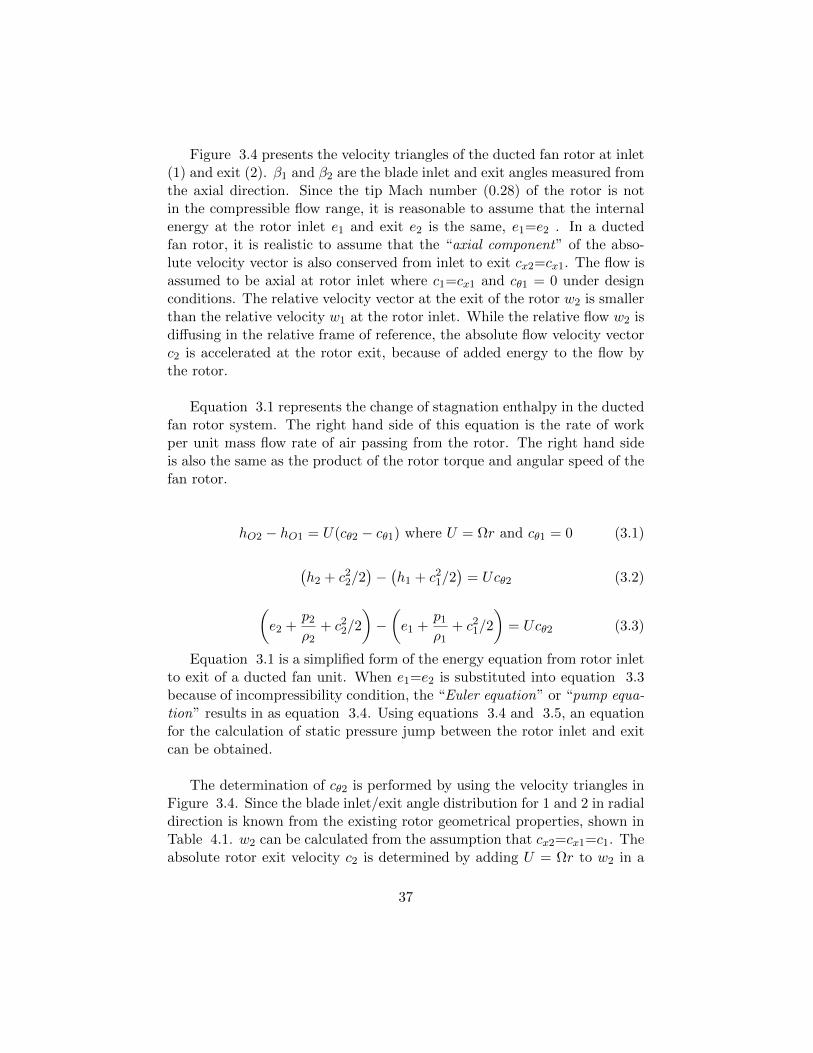
Figure 3.4 presents the velocity triangles of the ducted fan rotor at inlet(1) and exit (2). β1 and β2 are the blade inlet and exit angles measured fromthe axial direction. Since the tip Mach number (0.28) of the rotor is notin the compressible flow range, it is reasonable to assume that the internalenergy at the rotor inlet e1 and exit e2 is the same, e1=e2 . In a ductedfan rotor, it is realistic to assume that the “axial component” of the abso-lute velocity vector is also conserved from inlet to exit cx2=cx1. The flow isassumed to be axial at rotor inlet where c1=cx1 and cθ1 = 0 under designconditions. The relative velocity vector at the exit of the rotor w2 is smallerthan the relative velocity w1 at the rotor inlet. While the relative flow w2 isdiffusing in the relative frame of reference, the absolute flow velocity vectorc2 is accelerated at the rotor exit, because of added energy to the flow bythe rotor.
Equation 3.1 represents the change of stagnation enthalpy in the ductedfan rotor system. The right hand side of this equation is the rate of workper unit mass flow rate of air passing from the rotor. The right hand sideis also the same as the product of the rotor torque and angular speed of thefan rotor.
hO2 − hO1 = U(cθ2 − cθ1) where U = Ωr and cθ1 = 0 (3.1)
(h2 + c22/2
)−(h1 + c21/2
)= Ucθ2 (3.2)
(e2 +
p2ρ2
+ c22/2
)−(e1 +
p1ρ1
+ c21/2
)= Ucθ2 (3.3)
Equation 3.1 is a simplified form of the energy equation from rotor inletto exit of a ducted fan unit. When e1=e2 is substituted into equation 3.3because of incompressibility condition, the “Euler equation” or “pump equa-tion” results in as equation 3.4. Using equations 3.4 and 3.5, an equationfor the calculation of static pressure jump between the rotor inlet and exitcan be obtained.
The determination of cθ2 is performed by using the velocity triangles inFigure 3.4. Since the blade inlet/exit angle distribution for 1 and 2 in radialdirection is known from the existing rotor geometrical properties, shown inTable 4.1. w2 can be calculated from the assumption that cx2=cx1=c1. Theabsolute rotor exit velocity c2 is determined by adding U = Ωr to w2 in a
37

vectorial sense.
1
ρ(PO2 − PO1) = Ucθ2 (3.4)
(p2 + ρ
c222
)−(p1 + ρ
c212
)= ρUcθ2 (3.5)
∆p = p2 − p1 = ρ
[Ucθ2 −
1
2
(c22 − c21
)](3.6)
Equation 3.6 allows enforcing a prescribed pressure jump p in functionof density, radial position, rotor angular speed Ω , rotor exit swirl velocitycθ2 , c1 and c2 . The rate of energy (per unit mass flow rate) added to theflow by the rotor is specified by the product Ucθ2 as shown in equations 3.4and 3.5. Equation 3.6 could be evaluated at each radial position betweenthe rotor hub and tip resulting in the radial distribution of the static pres-sure jump required by the general purpose viscous flow solver for a “Fan”type boundary condition. ∆p can be effectively specified in a user definedfunction “UDF” in the solver(See Appendix ?? for details on UDF). The“Fan” type boundary condition is an effective and time efficient method ofimplementing a rotor flow field via an “actuator disk model” in a 3D viscousflow computation.
Details of the computational method can be found in [41].
38

Chapter 4
DDF Concept Validation
A three dimensional simulation of the mean flow field around the ductedfan was performed using a custom developed actuator disk model basedon radial equilibrium theory implemented into the commercial code Ansys-Fluent. The specific computational system solves the Reynolds AveragedNavier-Stokes (RANS) equations using a finite volume method. Details ofthe computational method can be found in section 3.
4.1 Reference Ducted Fan Characteristics
Figure 4.1 shows the five bladed reference ducted fan that is used in thepresent DDF development effort. The relatively poor forward flight charac-teristics of the reference ducted fan shown in Figure 4.1 are significantlyimproved via the new double ducted fan (DDF) concept that is explainedin the next few paragraphs. The geometric specifications of the referenceducted fan unit that is designed for small scale uninhabited aircraft arepresented in table 4.1. This unit is manufactured from carbon compositematerial and has six vanes at the exit of the fan in order to remove someof the swirl existing at the exit of the rotor. A tail cone is used to coverthe motor surface and hide the electrical wiring. All computational 3D flowsimulations of the reference duct including the rotor flow field are performedat 9000 rpm using the geometry defined in Figure 4.1.
39

Figure 4.1: Reference ducted fan and fan rotor used for DDF developmenteffort
40

Rotor hub diameter 52 mmRotor tip diameter 120 mmBlade height h 34 mmTip clearance t/h 5.8 %Max blade thickness at rotor tip 1.5 mmTailcone diameter 52 mmTailcone length 105 mm
Rotor blade section properties
Hub Mid Span TipBlade inlet angle β1 60o 40o 30o
Blade exit angle β2 30o 45o 60o
Blade chord 32 mm 30 mm 28 mm
Table 4.1: Geometric specifications of five inch ducted fan
4.2 Air Breathing Character of DDF in ForwardFlight
Table 4.2 presents the computed fan rotor mass flow rate for all ducted fantypes studied in this paper for both hover and forward flight conditions. Inaddition to hover conditions, the results are also presented for 10 m/s and20 m/s forward flight velocities at 9000 rpm rotor speed that is constant forall computations.
Fan Mass Flow Rate (kg/s) Thrust (N) Pitching Moment (N.m) Flight ConditionBaseline Duct 0.30 3.04 0.00 No Crosswind (Hover)Baseline Duct 0.29 3.47 0.17 10 m/s CrosswindBaseline Duct 0.20 3.11 0.27 20 m/s Crosswind
MODIFIED DUCTS (DDF)CASE-A 0.31 5.02 0.00 No Crosswind (Hover)CASE-A 0.31 4.93 0.37 10 m/s CrosswindCASE-A 0.26 5.07 0.83 20 m/s CrosswindCASE-B 0.30 3.02 0.00 No Crosswind (Hover)CASE-B 0.30 3.72 0.16 10 m/s CrosswindCASE-B 0.28 4.86 0.29 20 m/s Crosswind
Table 4.2: Computed rotor mass flow rate for all fan configurations duringhover and forward flight
Constant rpm flow simulations provide a basis for comparisons of 3Dmean flow, fan thrust, nose-up pitching moment, total pressure and staticpressure fields. Although the rotor speed is constant for all computations,the amount of mechanical energy transferred to the air during its passage
41

through the rotor varies, because of highly varying inlet flow field into theducted fan unit during hover, forward flight at 10 m/s and 20 m/s. Table4.2 also provides the computational estimates of thrust, nose-up pitchingmoment for hover and forward flight conditions.
Figure 4.2: Rotor disk mass flow rate versus forward flight speed at 9000rpm
Figure 4.2 shows that the baseline duct suffers from a high level of “inletflow distortion” at 10 m/s and 20 m/s forward flight velocity. The overallmass flow rate passing from the ducted fan is reduced to 66 % of the hovermass flow rate as shown by the red line in Figure 4.2 (for 20 m/s forwardflight). This significant limitation on the rotor mass flow rate is mainly theresult of the large separated flow region occurring at just downstream of thelip section of the leading side of the duct as shown in Figure 2.1. Whilethe leading side of the baseline duct passes a severely limited amount of airmass, the trailing side of the duct is able to breathe at a better rate thanthe leading side. It is apparent that the leading side of the baseline duct ispartially blocked at high forward flight velocities. Figure 4.2 also shows a
42

significant drop in rotor mass flow rate when the forward flight velocity isincreased from 10 m/s to 20 m/s.
Baseline duct mass flow rate, thrust and nose-up pitching mo-ment: Table 4.2 contains nose-up pitching moment information for allflight regimes showing a measurable increase in the pitching moment whenthe baseline vehicle moves at 10 m/s and 20 m/s in comparison to hoverconditions. The nose-up pitching moment is measured with respect to thecenter of gravity of the ducted fan unit for all cases. At 20 m/s forward flightcondition, the predicted pitching moment is 1.6 times that of the pitchingmoment at 10 m/s flight velocity. The pitching moment generation on a typ-ical ducted fan in forward flight is directly related to the extent of inlet lipseparation, the impingement of the rotor inlet flow on the duct inner surface(aft shroud surface) on the trailing side of the duct, imbalance of the rotorexit field between the leading side (low momentum) and trailing side (highmomentum), aerodynamic profiling of the duct outer surface especially nearthe leading side.
Predicted baseline ducted fan thrust values at 10 m/s and 20 m/s in-crease to 1.5 times and 1.7 times of the thrust of the baseline duct at hoverconditions. This relative thrust improvement is due to the specific externalshape of the baseline duct and modified rotor inlet conditions at elevatedforward speed levels.
Mass flow rate, thrust and nose-up pitching moment charac-teristics of CASE-A : The air breathing character of the baseline ductcan be significantly improved by implementing the tall double ducted fan(DDF) designated as CASE-A as shown in Figure 4.2. The mass flow rateof CASE-A is about 8 % more than that of the baseline duct operating atthe forward speed of 10 m/s. The rotor mass flow rate improvement forCASE-A at 20 m/s is much higher than that of the baseline duct operatingat 20 m/s. A 30 % improvement over the baseline duct is possible. Thisrelative mass flow rate improvement is a direct result of reduced inlet lipseparation near the leading side of the duct designs at forward flight.
The predicted thrust for the tall double ducted fan (DDF) CASE-A ismarkedly higher than that of the baseline duct. At 10 m/s horizontal flightvelocity, the thrust of CASE-A is about 1.7 times that of the baseline duct.When the flight velocity is elevated to 20 m/s, CASE-B produces an aug-mented thrust value of 1.9 times that of the baseline duct. The reduction
43

of the inlet lip separation results in a direct improvement of the ducted fanexit flow near the leading side of the duct. The thrust improvements are dueto both ducted fan exit flow improvements near the leading side of the unit,the external aerodynamic shape of the outer duct. The leading side of theDDF CASE-A rotor plane breathes air from the inlet at a much-improvedrate than that of the trailing side. The tall (DDF) CASE-A also entrains ameasurable amount of air into the outer duct from the inlet area of the unitespecially near the trailing side. The flow in the outer duct is in oppositedirection to the rotor flow near the leading side. However, the outer ductflow for the circumferential positions away from the leading side of the ductis in the same direction as the main rotor flow direction. Additional thrustaugmentation is possible in the outer duct at positions away from the lead-ing edge.
Although the tall (DDF) CASE-A is an excellent thrust producer at highforward flight velocities, it has the capability of augmenting the usually un-wanted nose-up pitching moment mainly because of the external shape ofthe outer lip at elevated forward flight velocities. The pitching moment pre-dicted at 10 m/s is about 2.2 times that of the baseline duct. At 20 m/s,the pitching moment produced by CASE-A is about 3.1 times that of thebaseline duct value. The reason the short ducted fan CASE-B was designedand developed was the need to reduce the unwanted pitching up momentgeneration unique to CASE-A.
An effective DDF design CASE-B with highly reduced nose-uppitching moment: CASE-B as shown in Figure 4.2 is a shorter versionof the double ducted fan design concept. CASE-B is designed to producea significantly reduced nose-up pitching moment when compared to CASE-A. Another goal with CASE-B is to obtain similar thrust gains over thebaseline duct. The short double ducted fan (DDF) CASE-B controls thelip separation as effectively as the tall (DDF) CASE-A without producing ahigh nose-up pitching moment. The airfoil geometry forming the outer ducthas an axial chord length that is about half of the axial chord of the innerduct (also termed as standard fan or baseline fan). A detailed description ofobtaining a short double ducted fan (DDF) CASE-B is given in Figure 2.2a.starting from a baseline duct. Figure 4.2 indicates that the mass flow rateimprovement (black line) of CASE-B is very similar to CASE-A (blue line).The short (DDF) CASE-B ’s sensitivity to increasing forward flight velocityis much less when compared to tall (DDF) CASE-A. Implementation of asecond duct as shown in Figure 2.2b enhances the lip separation controlled
44
flight zone further into higher forward flight velocities. The thrust valuespredicted for the short (DDF) are much higher than the standard duct pre-dictions at 10 m/s and 20 m/s. There is a slight reduction in thrust whencomparison is made against the tall (DDF) CASE-A. The most significantproperty of CASE-B is its ability to control nose-up pitching moment ef-fectively. The pitching moment generation for the short (DDF) CASE-Bis very much suppressed when compared to tall (DDF) CASE-A. CASE-Bnose-up pitching moments are about the same as the values predicted for thebaseline duct. The short (DDF) concept described in Figure 6.b is a highlyeffective scheme of improving the lip separation related inlet flow distortionproblem for the rotor of a ducted fan based VTOL/STOL vehicle. CASE-Bis able to improve thrust without increasing the nose-up pitching momentgeneration. Since the leading side of the fan exit jet is well balanced againstthe trailing side of the exit jet, the effectiveness of the control surfaces atthe exit of the ducted fan are expected to function much effectively for theshort (DDF) CASE-B.
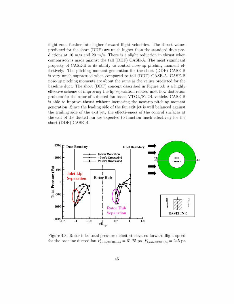
Figure 4.3: Rotor inlet total pressure deficit at elevated forward flight speedfor the baseline ducted fan Pt,inlet@10m/s = 61.25 pa ,Pt,inlet@20m/s = 245 pa
45

Figure 4.3 shows the total pressure obtained 1mm upstream of the base-line ducted fan rotor for hover, and two forward flight velocities. The span-wise total pressure distribution between the duct leading edge and trailingedge for hover condition shows a relatively flat total pressure distributionat the inlet surface. The inlet field is symmetrical between the leading sideand trailing side along a radial line passing from the axis of rotation.
When the baseline ducted fan increases its forward flight speed to 10 m/s,a very visible inlet total pressure defect due to leading side lip separationis apparent as shown by the green symbols in Figure 10. At 20 m/s for-ward flight speed, the total pressure defect near the leading side of the ductis significantly increased (blue symbols). The low momentum fluid enteringthe leading side of the rotor occupies a much wider portion of the blade span.
The trailing side of the rotor shows a very different inlet total pres-sure distribution along the flight direction as shown in Figure 4.3. Theinlet flow passing over the inlet plane tends to stagnate on the trailing sideof the baseline duct aft surface (shroud) due to the specific orientation ofinlet streamlines in this region, especially at elevated forward flight veloci-ties. The triangular and diamond symbols representing 10 m/s and 20 m/sforward flight velocities show the elevated levels of total pressure near thetrailing side of the duct inner surface. This type of total pressure augmenta-tion only occurring during forward flight is directly related to an unwanteddrag force acting in opposite direction to forward flight direction.
Figure 4.3 also reveals another local flow separation zone in the trailingside of the baseline duct inlet surface. The inlet flow progressing to enterinto the trailing portion of the duct also separates from the the rotor hubsurface, generating a low momentum zone as shown in Figure 4.3.
Figure 4.3 clearly shows the imbalance between the leading side andtrailing side of the duct inlet flow field in terms of local total pressure. Theduct has tremendous air breathing difficulty near the leading side of theduct. Due to blocked nature of the leading side flow, the trailing side seesan inlet flow with an unnecessarily elevated level of total pressure near theshroud surface. However there is a significant total pressure deficit near thehub surface for forward flight conditions due to rotor hub corner separation.
The short double ducted fan (DDF) CASE-B has an ability to controlthe inlet lip separation leading to improved thrust and well controlled nose-
46

Figure 4.4: Reduction in rotor inlet flow distortion between the leading sideand trailing side of (DDF) CASE-B short double ducted fanPt,inlet@20m/s = 245 pa
up pitching moment. Figure 4.4 shows the lip separation improvements ofCASE-B in comparison to the baseline duct.The black square symbols de-fine the rotor inlet total pressure distribution in spanwise direction for thebaseline fan under hover conditions. The inlet flow under hover conditionsdoes not have any significant inlet flow distortion for the baseline ducted fan.
Inlet flow character of the baseline ducted fan in horizontal flight is rep-resented by the black diamond symbols for the forward flight speed of 20m/s. The green circular symbol shows the inlet total pressure distributiongenerated by the short double ducted fan (DDF) CASE-B. The inlet lipseparation related total pressure deficit of the baseline configuration is ef-fectively reduced by the use of the short double-ducted fan (DDF) CASE-B(green circular symbols in Figure 4.4). The local mass flow rate passing
47
from the leading side of the duct is much improved because of the shortdouble-ducted fan (DDF) CASE-B. The unnecessarily elevated total pres-sure observed near the aft shroud of the baseline ducted fan (trailing side)as shown by black diamond symbols is also controlled when CASE-B is im-plemented (green circular symbols). This reduction of total pressure on thetrailing side of (DDF) CASE-B is beneficial in balancing the leading sideand trailing side flow of the fan rotor exit flow field. CASE-B also reducesdrag generation occurring near the aft part of the shroud.
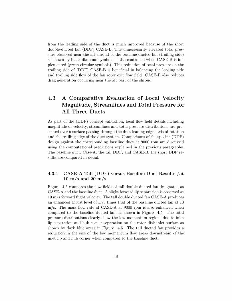
4.3 A Comparative Evaluation of Local VelocityMagnitude, Streamlines and Total Pressure forAll Three Ducts
As part of the (DDF) concept validation, local flow field details includingmagnitude of velocity, streamlines and total pressure distributions are pre-sented over a surface passing through the duct leading edge, axis of rotationand the trailing edge of the duct system. Comparisons of the specific (DDF)design against the corresponding baseline duct at 9000 rpm are discussedusing the computational predictions explained in the previous paragraphs.The baseline duct; Case-A, the tall DDF; and CASE-B, the short DDF re-sults are compared in detail.
4.3.1 CASE-A Tall (DDF) versus Baseline Duct Results /at10 m/s and 20 m/s
Figure 4.5 compares the flow fields of tall double ducted fan designated asCASE-A and the baseline duct. A slight forward lip separation is observed at10 m/s forward flight velocity. The tall double ducted fan CASE-A producesan enhanced thrust level of 1.73 times that of the baseline ducted fan at 10m/s. The mass flow rate of CASE-A at 9000 rpm is also enhanced whencompared to the baseline ducted fan, as shown in Figure 4.5. The totalpressure distributions clearly show the low momentum regions due to inletlip separation and hub corner separation on the rotor disk inlet surface asshown by dark blue areas in Figure 4.5. The tall ducted fan provides areduction in the size of the low momentum flow areas downstream of theinlet lip and hub corner when compared to the baseline duct.
48

Figure 4.5: Velocity magnitude and total pressure distribution,baseline ductversus CASE-A tall double ducted fan (DDF) at 10 m/s forward flight ve-locity
Although the “hub corner separation” area is relatively smaller thanthe “inlet lip separation” area, the flow blockage created by the hub cornerseparation affects the flow downstream of the rotor as shown in Figure 4.5.The total pressure imbalance observed at downstream of the rotor for thebaseline duct is significant. The existence of the tall double ducted fan
49

CASE-A slightly improves the total pressure on the leading side of the rotorexit flow for 10 m/s forward flight velocity.
Figure 4.6: Total pressure distribution at rotor exit plane (horizontal) base-line duct versus CASE-A tall double ducted fan (DDF) at 10 m/s forwardflight velocity
Figure 4.6 explains the effect of inlet flow distortion existing in the base-line duct and tall double ducted fan design at 10 m/s forward flight velocityby using rotor exit total pressure predictions. The light green zone nearthe leading side of the baseline ducted fan shows the highest level of aero-dynamic loss resulting from “inlet lip separation” at 10 m/s. This area iswhere the relative flow tends to separate because of the existence of the ductlip near the leading side. The fan inlet surface also has another aerodynamicloss region (green) at just downstream of the “hub corner” on the trailingside of the duct. The beneficial influence of the tall double ducted fan designCASE-A is shown in Figure 4.6. The aerodynamic loss areas in the baselineduct distribution are effectively reduced in the tall double ducted fan design.The red total pressure zone near the trailing side of the baseline duct showsthe highest levels of total pressure over the rotor exit plane. The trailingside tends to pass most of the inlet mass flow rate including the fluid that
50

is skipping over (deflected by) the lip separation region. This is a commonobservation in most standard ducted fans in horizontal flight.
The aft part of the fan usually generates additional drag force becauseof this red high total pressure zone at the exit plane. The implementationof the tall double ducted fan makes the total pressure distortion betweenthe leading side and trailing side much more balanced. The inlet flow dis-tortion is efficiently dealt with with the implementation of the second ductconfiguration termed as CASE-A, Figure 4.6.
When forward flight velocity is increased to 20 m/s, Figure 4.7 showsthe highly adverse character of the separated flow zone behind the inlet lipsection in the baseline duct. The flow also tends to separate behind the hubcorner on the trailing side of the duct. Figure 4.7 demonstrates that theflow is nearly blocked by the existence of a large separated flow zone and theflow is effectively induced into the trailing side of the duct. The imbalancein the local mass flow rate between the leading side of the duct and thetrailing side of the duct at 20 m/s is much more apparent when comparedto 10 m/s results. Figure 4.7 displays the significant flow improvementin the lip separation area for the tall double ducted fan (DDF) CASE-A.The re-circulatory flow is almost eliminated downstream of the lip. Theleading side of the duct starts breathing effectively because of CASE-A’sability to eliminate inlet flow distortion near the leading side. The (DDF)CASE-A results show a low momentum region that could be viewed as athree dimensional wake region behind the vehicle at 20 m/s forward flightvelocity. The outer duct flow near the leading side is in a direction oppositeto rotor flow direction. The outer duct flow near the leading side is anessential component of the (DDF) concept because of its higly importantrole in reversing the inner lip region separated flow conditions. The outerduct flow smoothly reverses into the rotor flow direction away from theleading side.
The rotor exit plane total pressure distribution shown in Figure 4.8,(DDF) CASE-A reveals a significant lip separation improvement leading toa much uniform inlet flow distribution between the leading side and trailingside of the inner duct. The DDF duct local flow distribution at the rotor exitis much improved in comparison to the baseline duct. Hub corner separationarea is also reduced in (DDF) CASE-A. Most circumferential positions ofthe second duct (other than the leading side of the duct) contributes to thegeneration of thrust because of the measurable outer duct flow observed in
51

Figure 4.7: Velocity magnitude and total pressure distribution, baselineduct versus CASE-A tall double ducted fan (DDF) at 20 m/s forward flightvelocity
52
this area.
Figure 4.8: Total pressure distribution at rotor exit plane (horizontal) base-line duct versus CASE-A tall double ducted fan (DDF) at 20 m/s forwardflight velocity
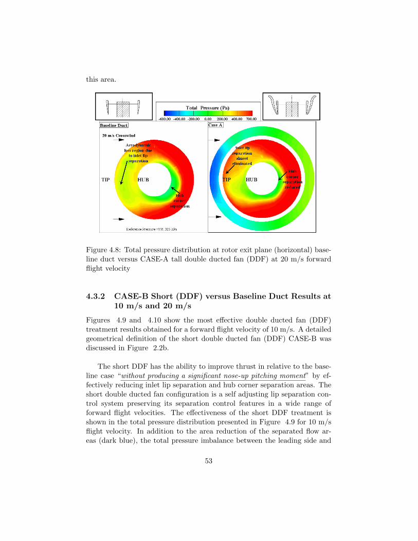
4.3.2 CASE-B Short (DDF) versus Baseline Duct Results at10 m/s and 20 m/s
Figures 4.9 and 4.10 show the most effective double ducted fan (DDF)treatment results obtained for a forward flight velocity of 10 m/s. A detailedgeometrical definition of the short double ducted fan (DDF) CASE-B wasdiscussed in Figure 2.2b.
The short DDF has the ability to improve thrust in relative to the base-line case “without producing a significant nose-up pitching moment” by ef-fectively reducing inlet lip separation and hub corner separation areas. Theshort double ducted fan configuration is a self adjusting lip separation con-trol system preserving its separation control features in a wide range offorward flight velocities. The effectiveness of the short DDF treatment isshown in the total pressure distribution presented in Figure 4.9 for 10 m/sflight velocity. In addition to the area reduction of the separated flow ar-eas (dark blue), the total pressure imbalance between the leading side and
53

Figure 4.9: Velocity Magnitude and total pressure distribution, baselineduct versus CASE-B short double ducted fan (DDF) at 10 m/s forwardflight velocity
trailing side is almost eliminated. The leading side of the inner duct of theshort DDF CASE-B breathes at a much improved rate as compared to thebaseline case. The red high total pressure areas provide a well-balanced fan
54

exit jet near the leading side and trailing side of the fan.
Figure 4.10: Total pressure distribution at rotor exit plane (horizontal) base-line duct versus CASE-B short double ducted fan (DDF) at 10 m/s forwardflight velocity
Figure 4.10 indicates a high level of rotor exit total pressure uniformityfor CASE-B in contrast to the strong flow distortion generated by the base-line duct. When short double ducted fan is used, the lip separation and hubcorner separation control is highly effective at 10 m/s flight velocity. Thelevel of total pressure values between the leading side and trailing side aremuch better balanced in CASE-B as shown in Figure 4.10.
When the short double ducted fan arrangement (DDF) CASE-B is eval-uated at 20 m/s flight velocity, the loss elimination features near the leadingside lip, hub corner area are much apparent. Highly separated lip regionflow adversely blocking the leading side of the inner duct is successfullydealt with the flow control features of the short (DDF) as shown in Figure4.11. A well-balanced short (DDF) exit flow provides a higher level of thrustwhen compared to the baseline duct. The flow improvements and thrust en-hancement from the short (DDF) comes with no additional nose-up pitching
55

Figure 4.11: Velocity magnitude and total pressure distribution, baselineduct versus CASE-B short double ducted fan (DDF) at 20 m/s forwardflight velocity
moment generation when compared to baseline as explained in Table 4.2
56

and Figure 4.11. A highly effective inlet flow distortion control ability of theshort ducted fan can be apparently seen in Figure 4.12. A vehicle using theshort (DDF) concept CASE-B generates a higher level of thrust with a wellbalanced ducted fan exit flow without excessive generation of nose-up pitch-ing moment. This approach results in improvements of the performance ofthe control surfaces and improved range because the energy efficiency of theducted fan is improved. The elimination of severe inlet flow distortion islikely to improve the rotor exit flow quality before further interaction withtypical control surfaces.
Figure 4.12: Total pressure distribution at rotor exit plane (horizontal) base-line duct versus CASE-B short double ducted fan (DDF) at 20 m/s forwardflight velocity
4.4 Upstream Lip Region Local Flow Improvementsin (DDF)
Figure 4.13 defines the local sampling locations for static pressure and skinfriction coefficient computations on the airfoil of the inner duct at the leading
57

edge location. The lowercase characters represent the “rotor side” locationsand the uppercase characters show the “outer side” sampling locations forstatic pressure and skin friction coefficient on the inner duct airfoil section.The “outer side” denotes the channel between the baseline duct and sec-ondary duct.
Figure 4.13: Sampling locations for static pressure and skin friction co-efficient computations near the leading side of the inner duct for (DDF)CASE-B
4.4.1 Static Pressure Distribution around the Lip Section ofthe Baseline Duct
Figure 4.14 shows the static pressure distribution for the baseline ductand double ducted fan (DDF) CASE-B for the forward flight velocity of20 m/s. The distributions presented in Figure 4.14 are plotted aroundthe airfoil of the baseline duct. The pressure gradient occurring aroundthe leading edge radius of the inner duct is the most significant parametercontrolling severeness of the leading edge lip separation problem. Pointx=X/c=0 shows the leading edge and x=X/c=1 shows the trailing edgelocation of the baseline duct airfoil. The external flow stagnates on the thebaseline duct airfoil at point D as shown in Figure 4.14 . The approachingflow to the duct is divided into a stream reaching up to the leading edge anda second stream approaching down to the trailing edge of the duct airfoilat point D. The static (or stagnation) pressure from point D to J remainsalmost constant. The external flow slightly accelerates to the leading edge
58

point from point C to A for the baseline duct. There is a strong accelerationzone between point A and the leading edge point O, as clearly shown bythe favorable pressure gradient between the point A and O. This is the areawithin the leading edge diameter of the inner lip section. The geometricalleading edge point O is the minimum pressure point for the baseline ductairfoil. The flow on the inner side of the lip sees a very strong adversepressure gradient around the leading edge circle. The strong flow separationcharacter shown in Figure 4.14 is mainly due to the strong adverse pressuregradient affecting the boundary layer growth between points O, a and finallyb. The rotor process described in equations from 3.1 to 3.6 results in thesudden pressure rise on the inner part of the baseline duct between b and c.
Figure 4.14: Comparison of the static pressure distribution on the baselinelip section and inner duct lip section of the (DDF) CASE-B airfoil
4.4.2 Static Pressure Distribution around the Lip section ofthe Double Ducted Fan (DDF)
Figure 4.14 also shows the static pressure distribution around the lip sec-tion of the short double ducted fan (DDF) CASE-B. The vertically upwardchannel flow in the outer duct section is established by the dynamic pressureof the external flow in forward flight. The vertically upward flow exists in anarrow leading edge region as clearly shown in Figure 4.11 and the results
59
showing the axial velocity vectors from the computations. The outer ductflow that is proceeding vertically up generates a unique wall static pressuredistribution in a converging-diverging channel. The external flow in hori-zontal flight stagnates on the shorter outer airfoil and turns upward towardsthe leading edge of the outer duct airfoil. Most of the flow stagnating atthe lower part of the vehicle is directed towards the converging divergingchannel of the outer duct. There is a wide stagnation region between pointsJ and H on the outer side of the inner duct. The flow accelerates towardsthe throat section of the outer duct near D. The flow after the throat sectionsmoothly decelerates up to the point A that is very close to the leading edgecircle of the leading edge. The existence of the diverging channel is responsi-ble from a much softer acceleration around the leading edge diameter of thelip section between A and O. The flow is still accelerating when it is pass-ing through the geometrical leading edge point O. The minimum pressurepoint (MP) in (DDF) configuration is on the inner side of the lip sectionat x=X/c=0.03 in contrary to the baseline duct location O. The flow startsdecelerating after this minimum pressure point MP. The adverse pressuregradient region after the minimum pressure point MP in (DDF) is muchshorter and the adverse pressure gradient between MP and a is much milderthan that of the baseline duct. Figure 4.14 clearly shows the favorablemodified nature of the static pressure distribution around the lip section of(DDF) leading to the elimination of the severe inlet lip separation regionthat is unique to the baseline duct in forward flight. The (DDF) approachis extremely useful in controlling the inner lip flow separation originatingthe adverse pressure gradient region.
4.4.3 Skin Friction Distribution around the Leading Edge ofthe Duct
Figure 4.15 presents the skin friction coefficient distributions on the baselineduct lip section and inner duct lip section of the (DDF) configuration. Theskin friction coefficient cf is defined as the local wall shear stress normalizedby inlet dynamic head defined as the lowest level of the predicted wall shearstress is on the lip surface along the separated flow region for the baselineduct. This low momentum region is between points O and a correspondingto the highest level of adverse pressure gradients before the rotor inlet plane.The overall level of wall shear stress is higher between points a and b forthe double duct configuration showing the immediate influence of weakenedadverse pressure gradients resulting from the (DDF) geometry. The DDF
60

Figure 4.15: Comparison of the skin friction coefficient distribution on thebaseline lip section and inner duct lip section of the (DDF) airfoil
geometry significantly reduces the aerodynamic shear stress occurring nearthe inner lip of the DDF system especially near the leading edge.
61

Chapter 5
Conclusions
This technical paper describes a novel ducted fan inlet flow conditioningconcept that will significantly improve the performance and controllabil-ity of VTOL “vertical take-off and landing” vehicles, UAVs “uninhabitedaerial vehicles” and many other ducted fan based systems. The new (DDF)concept developed in this study deals with most of the significant technicalproblems in ducted fans operating at almost 90o angle of attach, in the edge-wise flight mode. The technical problems related to this mode of operationare as follows:
• Increased aerodynamic losses and temporal instability of the fan rotorflow when “inlet flow distortion” from “the lip separation area” findsits way into the tip clearance gap leading to the loss of energy additioncapability of the rotor.
• Reduced thrust generation from the upstream side of the duct due tothe rotor breathing low-momentum re-circulatory turbulent flow.
• A severe imbalance of the duct inner static pressure field resultingfrom low momentum fluid entering into the rotor on the leading sideand high momentum fluid unnecessarily energized on the trailing sideof the rotor.
• A measurable increase in power demand and fuel consumption whenthe lip separation occurs to keep up with a given operational task.
• Lip separation and its interaction with the tip gap flow requires amuch more complex vehicle control system because of the severe non-uniformity of the exit jet in circumferential direction and excessivepitch-up moment generation.
62

• At low horizontal speeds a severe limitation in the rate of descentand vehicle controllability may occur because of more pronounced lipseparation. Low power requirement of a typical descent results in alower disk loading and more pronounced lip separation.
• Excessive noise and vibration from the rotor working with a significantinlet flow distortion.
• Very complex unsteady interactions of duct exit flow with control sur-faces.
The new concept that will significantly reduce the inlet lip separationrelated performance penalties in the edgewise flight zone is named “DOU-BLE DUCTED FAN (DDF)”. The current concept development uses a timeefficient 3D computational viscous flow solution approach developed specif-ically for ducted fan flows. The present study summarizes only the mostoptimal approach after evaluating nine different double ducted fan geome-tries for a wide range of edgewise flight velocities.
The current concept uses a secondary stationary duct system to control“inlet lip separation” related momentum deficit at the inlet of the fan rotoroccurring at elevated edgewise flight velocities. The DDF is self-adjustingin a wide edgewise flight velocity regime.
DDFs corrective aerodynamic influence becomes more pronounced withincreasing flight velocity due to its inherent design properties.
Case-B was the best DDF configuration designed. It has improved massflow rate passing from the duct by 40 % and improved thrust force obtainedfrom the ducted fan by 56.2 % relative to baseline duct in edgewise flightcondition.
63
The DDF can also be implemented as a “Variable Double Ducted Fan”(VDDF) for a much more effective inlet lip separation control in a wide rangeof horizontal flight velocities in UAVs, air vehicles, trains, buses, marine ve-hicles and any axial flow fan system where there is significant lip separationdistorting the inlet flow.
Most axial flow fans are designed for an inlet flow with zero or minimalinlet flow distortion. The DDF concept is proven to be an effective way ofdealing with inlet flow distortions occurring near the tip section of any axialflow fan rotor system operating at high angle of attack.
64

Bibliography
[1] Abrego, A. I. and Bulaga, R. W., 2002, “Performance study of a ductedfan system,” AHS Aerodynamics, Aeroacoustic , Test and EvaluationTechnical Specialist Meeting.
[2] Martin, P. and Tung, C., 2004, “Performance and flowfield measure-ments on a 10-inch ducted rotor vtol uav,” 60th Annual Forum of theAmerican Helicopter Society.
[3] Fleming, J., Jones, T., Lusardi, J., Gelhausen, P., and Enns, D., 2004,“Improved control of ducted fan vtol uavs in crosswind turbulence,”AHS 4th Decennial Specialist’s Conference on Aeromechanics.
[4] Moller, P. S., 1989, “Robotic or remotely controlled flying platform,”U.S. Patent No: 4795111.
[5] Graf, W., Fleming, J., and Wing, N., 2008, “Improving ducted fanuav aerodynamics in forward flight,” 46th AIAA Aerospace SciencesMeeting and Exhibit.
[6] Graf, W. E., 2005, Effects of Duct Lip Shaping and Various ControlDevices on the Hover and Forward Flight Performance of Ducted FanUAVs, Master’s thesis, Virginia Polytechnic Institute and State Uni-versity, Blacksburg, Virginia.
[7] Lazareff, M., 2008, “Improving ducted fan uav aerodynamics in forwardflight,” 46th AIAA Aerospace Sciences Meeting and Exhibit.
[8] Van Weelden, S. D., Smith, D. E., and Mullins, B. R., Jr., 1996, “Pre-liminary design of a ducted fan propulsion system for general aviationaircraft,” AIAA 34th Aerospace Sciences Meeting and Exhibit.
[9] Kriebel, A. R. and Mendehall, M. R., 1966, “Predicted and measuredperformance of two full-scale ducted propellers,” CAL/USAAVLABS
65

Symposium on Aerodynamic Problems Associated with V/STOL Air-craft, Vol II: Propulsion and Interference Aerodynamics.
[10] Mort, K. W. and Gamse, B., 1967, “A wind tunnel investigation of a7-foot-diameter ducted propeller,” Tech. Rep. NASA TND-4142.
[11] Mort, K. W. and Yaggy, P. F., 1962, “Aerodynamic characteristics ofa 4-foot-diameter ducted fan mounted on the tip of a semispan wing,”Tech. Rep. NASA TND-1301.
[12] Yaggy, P. F. and Mort, K. W., 1961, “A wind-tunnel investigation ofa 4-foot-diameter ducted fan mounted on the tip of a semispan wing,”Tech. Rep. NASA TND-776.
[13] Weir, R. J., 1988, “Aerodynamic design consideration for a free flyingducted propeller,” AIAA Atmospheric Flight Mechanics Conference.
[14] Pereira, J. L., 2008, Hover and Wind-tunnel Testing of Shrouded Ro-tors for Improved Micro Air Vehicle Design, Ph.D. thesis, Universityof Maryland, Maryland.
[15] Martin, P. B. and Boxwell, D. A., 2005, “Design, analysis and experi-ments on a 10-inch ducted rotor vtol uav,” AHS International Special-ists Meeting on Unmanned Rotorcraft: Design, Control and Testing.
[16] Lind, R., Nathman, J. K., and Gilchrist, I., 2006, “Ducted rotor per-formance calculations and comparisons with experimental data,” 44thAIAA Aerospace Sciences Meeting and Exhibit.
[17] He, C. and Xin, H., 2006, “An unsteady ducted fan model for rotorcraftflight simulation,” 62th AHS Forum.
[18] Chang, I. C. and Rajagopalan, R. G., 2003, “Cfd analysis for ductedfans with validation,” 21th AIAA Applied Aerodynamics Conference.
[19] Ahn, J. and Lee, K. T., 2004, “Performance prediction and design of aducted fan system,” 40th AIAA/ASME/SAE/ASEE Joint PropulsionConference and Exhibit.
[20] Ko, A., Ohanian, O. J., and Gelhausen, P., 2007, “Ducted fan uavmodeling and simulation in preliminary design,” AIAA Modeling andSimulation Technologies Conference and Exhibit.
[21] Zhao, H. W. and Bil, C., 2008, “Aerodynamic design and analysis of avtol ducted-fan uav,” 26th AIAA Applied Aerodynamics Conference.
66

[22] Dorman, H. A. and Dorman, B. A., 1960, “Aircraft having a pluralityof annular wings,” U.S. Patent No: 2951661.
[23] Bright, C. E., 1961, “Ducted fan aircraft,” U.S. Patent No: 2968453.
[24] Yoeli, R., 2002, “Ducted fan vehicles particularly useful as vtol air-craft,” U.S. Patent No: 6464166.
[25] Piasecki, F. N., 1965, “Flying platform,” U.S. Patent No: 3184183.
[26] Fletcher, C. I., 1961, “Ducted fan aircraft,” U.S. Patent No: 2988301.
[27] Boyd, E. S., Mallory, M., and Skinner, L. R., 1970, “Vertical takeoffand landing aircraft,” U.S. Patent No: 3519224.
[28] Wen, L., 1977, “Vertical takeoff and landing aircraft,” U.S. Patent No:4049218.
[29] Cycon, J. P., Rosen, K. M., and Whyte, A. C., 1992, “Unmanned flightvehicle including counter rotating rotors positioned within toroidalshroud and operable to provide all required vehicle flight control,” U.S.Patent No: 5152478.
[30] Moffit, R. C. and Owen, S. J., 1992, “Shroud geometry for unmannedaerial vehicles,” U.S. Patent No: 5150857.
[31] Flemming, R. J., Rosen, K. M., and Sheehy, T. W., 1995, “Ancillaryaerodynamic structures for an unmanned aerial vehicle having ducted,coaxial counter-rotating rotors,” U.S. Patent No: 5419513.
[32] Swinson, J., Walker, S., and James, T. J., 1999, “Horizontal and ver-tical take off and landing unmanned aerial vehicle,” U.S. Patent No:5890441.
[33] Cycon, J. P., Scott, M. W., and DeWitt, C. W., 2001, “Method ofreducing a nose-up pitching moment on a ducted unmanned aerial ve-hicle,” U.S. Patent No: 6170778.
[34] Cycon, J. P., Scott, M. W., and DeWitt, C. W., 2001, “Unmanned aerialvehicle with counter-rotating ducted rotors and shrouded pusher-prop,”U.S. Patent No: 6270038.
[35] Moller, P. S., 2002, “Stabilizing control apparatus for robotic or re-motely controlled flying platform,” U.S. Patent No: 6450445.
67

[36] Wagner, J., Pruszenski, A., and Milde, K. F., 2005, “Vtol personalaircraft,” U.S. Patent No: 6886776.
[37] Yoeli, R., 2005, “Vehicles particularly useful as vtol vehicles,” U.S.Patent No: 6883748.
[38] Yoeli, R., 2007, “Ducted fan vtol vehicles,” U.S. Patent No:2007/0034739.
[39] Yoeli, R., 2007, “Ducted fan vehicles particularly useful as vtol air-craft,” U.S. Patent No: 7275712.
[40] ANSYS, 2009, “Ansys-fluent v12 user’s guide,” .
[41] Akturk, A., 2010, Ducted Fan Inlet/Exit and Rotor Tip Flow Improve-ments for Vertical Lift Systems, Ph.D. thesis, The Pennsylvania StateUniversity, Pennsylvania.
68