Embed Size (px)
Citation preview

NOT FAA POLICY OR GUIDANCE LIMITED RELEASE DOCUMENT
23 NOVEMBER 2015
NOT FAA POLICY OR GUIDANCE LIMITED RELEASE DOCUMENT
23 November 2015
DOT/FAA/TC-xx/xx Federal Aviation Administration William J. Hughes Technical Center Aviation Research Division Atlantic City International Airport New Jersey 08405
SE2020 Task Order 22
Avionics Evolution Impact on Requirements Issues and Validation and Verification DISCLAIMER This draft document is being made available as a “Limited Release” document by the FAA Software and Digital Systems (SDS) Program and does not constitute FAA policy or guidance. This document is being distributed by permission by the Contracting Officer’s Representative (COR). The research information in this document represents only the viewpoint of its subject matter expert authors. The FAA is concerned that its research is not released to the public before full editorial review is completed. However, a Limited Release distribution does allow exchange of research knowledge in a way that will benefit the parties receiving the documentation and, at the same time, not damage perceptions about the quality of FAA research. This draft document does not include the Appendices due to scope of topics discussed. Applicability of their inclusion in the final version will be considered.
NOT FAA POLICY OR GUIDANCE LIMITED RELEASE DOCUMENT
23 November 2015
NOT FAA POLICY OR GUIDANCE LIMITED RELEASE DOCUMENT
23 November 2015
NOTICE
This document is disseminated under the sponsorship of the U.S. Department of Transportation in the interest of information exchange. The U.S. Government assumes no liability for the contents or use thereof. The U.S. Government does not endorse products or manufacturers. Trade or manufacturers’ names appear herein solely because they are considered essential to the objective of this report. The findings and conclusions in this report are those of the author(s) and do not necessarily represent the views of the funding agency. This document does not constitute FAA policy. Consult the FAA sponsoring organization listed on the Technical Documentation page as to its use.

NOT FAA POLICY OR GUIDANCE LIMITED RELEASE DOCUMENT
23 November 2015
NOT FAA POLICY OR GUIDANCE LIMITED RELEASE DOCUMENT
23 November 2015
Technical Report Documentation Page 1. Report No.
2. Government Accession No. 3. Recipient's Catalog No.
4. Title and Subtitle SE2020 Task Order 22 Avionics Evolution Impact on Requirements Issues and Validation and Verification, Phase 2/Final Report/DS #15.
5. Report Date October 15, 2015 November 23, 2015, Rev. A
6. Performing Organization Code
7. Author(s) Peter De Salvo and Daniel Fogarty
8. Performing Organization Report No.
9. Performing Organization Name and Address BOEING AEROSPACE OPERATIONS, INC. 6001 S AIR DEPOT OKLAHOMA CITY, OK 73135- 6601
10. Work Unit No. (TRAIS)
11. Contract or Grant No.
12. Sponsoring Agency Name and Address U.S. Department of Transportation Federal Aviation Administration Air Traffic Organization Operations Planning Office of Aviation Research and Development Washington, DC 20591
13. Type of Report and Period Covered Phase 2 Final Report
14. Sponsoring Agency Code AIR-134
15. Supplementary Notes Report revised on November 3, 2015 (Rev. A) in response to FAA review and feedback. The Federal Aviation Administration Aviation Research Division TOR was Charles Kilgore. 16. Abstract This document, DS #15, presents Phase 2 Final Report on the impact of avionics evolution on requirements issues and validation and verification. Design architectures and associated requirements for aerospace digital avionics systems have accelerated in complexity and integration over the last two decades. Initial generations of digital avionics automated individual functions that were stand-alone or had limited integration with other airplane-level functions. However, today’s complex avionics’ architectures can be highly integrated across complex systems. This research has been initiated to identify and address problems caused by, or that contributed to, incorrect or incomplete requirements. This report builds on research completed in years’ 1 and 2 of this Task Order that addressed safety issues with requirements’ definition, validation, and verification processes and practices, and root causes of requirements’ errors, omissions, or conflicts. Included is research based on input from Subject Matter Experts.
17. Key Words Requirements, validation, verification, safety, development assurance, ARP4754A, ARP4761, DO-178B/C, DO-254, DO-297.
18. Distribution Statement This document is available to the U.S. public through the National Technical Information Service (NTIS), Springfield, Virginia 22161.

NOT FAA POLICY OR GUIDANCE LIMITED RELEASE DOCUMENT
23 November 2015
NOT FAA POLICY OR GUIDANCE LIMITED RELEASE DOCUMENT
23 November 2015
19. Security Classif. (of this report) Unclassified
20. Security Classif. (of this page) Unclassified
21. No. of Pages 97
22. Price
Form DOT F 1700.7 (8-72) Reproduction of completed page authorized
NOT FAA POLICY OR GUIDANCE LIMITED RELEASE DOCUMENT
23 November 2015
NOT FAA POLICY OR GUIDANCE LIMITED RELEASE DOCUMENT
23 November 2015 i
ACKNOWLEDGEMENTS
The authors would like to acknowledge the following Federal Aviation Administration Review Team individuals for providing support to the project:
• Chakradhar Agava • Charles Kilgore • Srini Mandalapu • Robin Sova • John Zvanya

NOT FAA POLICY OR GUIDANCE LIMITED RELEASE DOCUMENT
23 November 2015
NOT FAA POLICY OR GUIDANCE LIMITED RELEASE DOCUMENT
23 November 2015 ii
TABLE OF CONTENTS
Page EXECUTIVE SUMMARY. vii 1. INTRODUCTION. 1
1.1 TASK BACKGROUND. 1 1.2 RESEARCH SCOPE. 2
2. AVIONICS EVOLUTION IMPACT ON REQUIREMENTS ISSUES AND
VERIFICATION AND VALIDATION. 3
3. RESEARCH APPROACH, FINDINGS, AND RECOMMENDATIONS. 8
3.1 INFORMATION COLLECTED FROM EXPERIENCED AVIONICS SYSTEMS SUBJECT MATTER EXPERTS. 9 3.1.1 Baseline Questionnaire and Subjects. 9 3.1.2 Questionnaire Results. 13 3.1.3 SME Questionnaire Findings. 17
3.2 EVALUATION OF REAL-WORLD SCENARIOS AND POSSIBLE REQUIREMENTS IMPACTS. 24 3.2.1 Candidate Requirements Issues and Potential Shortcomings. 24 3.2.2 Selected Real-World Avionics Scenarios and Detailed Analyses. 32 3.2.3 Integration of Real-World Avionics Scenarios and SME Questionnaire Responses. 43
3.3 ROOT CAUSES FOR REQUIREMENTS ISSUES AND SHORTCOMINGS. 46 3.3.1 Summary of Root Causes. 47 3.3.2 Candidate Areas for Improvement of Requirements Issues in Phase 3. 50
4. FINDINGS AND RECOMMENDATIONS. 52
5. REFERENCES. 53
APPENDICES
A— WHITE PAPER #1
B— WHITE PAPER #2
C— SUMMARY OF FINDINGS FROM PHASE 1 REPORT

NOT FAA POLICY OR GUIDANCE LIMITED RELEASE DOCUMENT
23 November 2015
NOT FAA POLICY OR GUIDANCE LIMITED RELEASE DOCUMENT
23 November 2015 iii
D— SCENARIO MAPPING
NOT FAA POLICY OR GUIDANCE LIMITED RELEASE DOCUMENT
23 November 2015
NOT FAA POLICY OR GUIDANCE LIMITED RELEASE DOCUMENT
23 November 2015 iv
LIST OF FIGURES Figure Page 1. Civil Airborne Software Development (Software Lines of Code by Decade) 6 2. Abstraction/Mental Model to Software 28 3. Integrated Systems 29 4. Vertical Integration of Requirements 31 5. Questionnaire Responses Combined With the Eight Scenarios 45

NOT FAA POLICY OR GUIDANCE LIMITED RELEASE DOCUMENT
23 November 2015
NOT FAA POLICY OR GUIDANCE LIMITED RELEASE DOCUMENT
23 November 2015 v
LIST OF TABLES
Table Page 1. SMEs’ Questionnaire 10

NOT FAA POLICY OR GUIDANCE LIMITED RELEASE DOCUMENT
23 November 2015
NOT FAA POLICY OR GUIDANCE LIMITED RELEASE DOCUMENT
23 November 2015 vi
LIST OF ABBREVIATIONS AND ACRONYMS
A/C Aircraft AC Advisory Circular AD Airworthiness Directive ADIRU Air Data Inertial Reference Unit AEH Airborne Electronic Hardware AIR Aerospace Information Report AR Authorized Representative ARP Aerospace Recommended Practice ATC Air Traffic Control ATSB Australian Transport Safety Bureau BCA Boeing Commercial Airplanes BITE Built-in Test Equipment BQN Borinquen International Airport CA California CAS Caution Advisory System CIA Change Impact Analysis DC District of Columbia DO Document DS Delivery Schedule ECL Electronic Checklist FAA Federal Aviation Administration FHA Functional Hazard Assessment FTA Fault Tree Analysis GPS Global Positioning System IMA Integrated Modular Avionics LRU Line Replaceable Unit IP Issue Paper MBSE Model-Based Systems Engineering MD McDonnell Douglas MIT Massachusetts Institute of Technology NASA National Aeronautics and Space Administration NTIS National Technical Information Services NTSB National Transportation Safety Board OEM Original Equipment Manufacturer PSSA Preliminary System Safety Assessment PVR Puerto Vallarta SAE Society of Automotive Engineers SE2020 Systems Engineering 2020 SEE Single Event Effects

NOT FAA POLICY OR GUIDANCE LIMITED RELEASE DOCUMENT
23 November 2015
NOT FAA POLICY OR GUIDANCE LIMITED RELEASE DOCUMENT
23 November 2015 vii
SME Subject Matter Expert SR Swissair SSA System Safety Assessment SW Software TO-22 Task Order 22 TSB Transportation Safety Board UTC Universal Coordinated Time V&V Validation and Verification
NOT FAA POLICY OR GUIDANCE LIMITED RELEASE DOCUMENT
23 November 2015
NOT FAA POLICY OR GUIDANCE LIMITED RELEASE DOCUMENT
23 November 2015 viii
EXECUTIVE SUMMARY
Design architectures and associated requirements for aerospace digital avionics systems have experienced acceleration in complexity and integration over the last two decades. Where initial generations of digital avionics automated individual functions that were often stand-alone or limited in integration with other airplane-level functions, today’s complex avionics’ architectures can be highly integrated across complex systems. The object of the work described in this Phase 2 Final Report was to classify and categorize problems with requirements’ definition and V&V processes, identify potential shortcomings, and identify root causes of requirements’ errors, omissions, or conflicts associated with complex digital systems. The research utilized systems engineering methods and involved two approaches: we solicited input from Boeing subject matter experts and evaluated eight scenarios for possible causes that might contribute to requirements errors, omissions, and conflicts. The research approach also included reviewing industry guidance for possible gaps in requirements formulation and validation and verification (V&V) for complex avionics’ architectures. The first five white papers reported the results of research: • To identify adverse events that requirements’ definition and V&V may have been, at a
minimum, a contributing factor, as necessary to identify instances of requirements’ errors, omissions, or conflicts from commercial aviation (Phase 1, White Paper 1).
• To identify and document requirements’ definition, V&V processes, and interfaces among the processes (Phase 1, White Paper 2).
• To study the identified requirements’ definition, V&V processes, and interfaces to highlight the issues and shortcomings (Phase 1, White Paper 3).
• To classify and categorize issues and shortcomings identified in prior white papers (Phase 2, White Paper 4).
• To identify the root causes of the requirements' errors, omissions, or conflicts (Phase 2, White Paper 5).

NOT FAA POLICY OR GUIDANCE LIMITED RELEASE DOCUMENT
23 November 2015
NOT FAA POLICY OR GUIDANCE LIMITED RELEASE DOCUMENT
23 November 2015 ix
Findings from this research were summarized into four major root causes that suggest potential improvements and additions to industry guidance related to: 1. Incomplete, incorrect, or missing requirements (see section 3.3.1.1).
2. Incorrect implementation of otherwise correct requirements (see section 3.3.1.2).
3. Incomplete, inadequate change impact analysis (see section 3.3.1.3).
4. Incomplete, incorrect programmatic and technical planning (see section 3.3.1.4).
This report also includes recommendations for future work (section 3.3.2, Candidate Areas for Improvement of Requirements Issues in Phase 3).

NOT FAA POLICY OR GUIDANCE LIMITED RELEASE DOCUMENT
23 November 2015
NOT FAA POLICY OR GUIDANCE LIMITED RELEASE DOCUMENT
23 November 2015 1
1. INTRODUCTION.
During the last two decades, the complexity and integration of design architectures and associated requirements for aerospace digital avionics systems have increased. While initial generations of digital avionics automated individual functions that were often stand-alone or limited in integration with other functions, today’s complex avionics’ architectures are highly integrated across complex systems. Furthermore, emerging next generation air traffic management systems are further integrating platform-level complex systems into a broader system of systems, where data is shared across aircraft and air traffic management resources without pilot/controller intervention. This evolution of increased complexity and integration has been noted by the Federal Aviation Administration (FAA) and industry alike. The purpose of this research effort is to examine possible relationships between requirements development, validation and verification (V&V) processes, and to identify the root causes of requirements’ errors, omissions, or conflicts. 1.1 TASK BACKGROUND.
Integrating complex systems has resulted in increased systems interdependence and integration. Compelling questions before both industry and regulators alike are as follows: • What are commonly accepted industry guidelines and practices used in requirements
capture, definition, and V&V processes?
• What does the trend of accelerated growth of systems’ complexity mean to our design and V&V practices?
• What changes are required in our approaches to address this trend?
Realization of this trend was one of the key drivers for the creation of the new Aerospace Recommended Practice (ARP) 4754 Revision A [1]. ARP4754 Rev New was originally developed in response to a request from the FAA to the Society of Automotive Engineers (SAE) to define an acceptable development assurance process for highly integrated and complex avionics systems [2]. The issuance of ARP4754 Rev A provides industry with a framework that addresses the growth of increased integration and complexity. In addition, the industry and regulators are considering further steps. This research highlights that ARP4754A can be improved with regard to the increased integration and complexity.
NOT FAA POLICY OR GUIDANCE LIMITED RELEASE DOCUMENT
23 November 2015
NOT FAA POLICY OR GUIDANCE LIMITED RELEASE DOCUMENT
23 November 2015 2
1.2 RESEARCH SCOPE.
The nature and scope of the research required to answer the questions posed above is divided into three phases. The Phase 1 research identified issues and shortcomings that contributed to incorrect or incomplete requirements definition, and V&V processes and practices. The current Phase 2 research classifies and categorizes Phase 1 issues and shortcomings along with root causes. The Phase 3 research will identify recommendations and solutions to the root causes identified in Phase 2. [3] To address potential process issues and shortcomings, the following industry process documents were reviewed: • SAE ARP4754A/EUROCAE ED-79A, “Guidelines for Development of Civil Aircraft
and Systems,” December 21, 2010, covering development assurance processes [1].
• SAE ARP4754/EUROCAE ED-79, “Certification Considerations for Highly Integrated or Complex Aircraft Systems,” 1996, likewise covering development assurance processes [2].
• SAE ARP 4761, “Guidelines and Methods for Conducting the Safety Assessment Process on Civil Airborne Systems,” 1996, describing safety assessment processes [4].
• DO-178B/C, “Software Considerations in Airborne Systems and Equipment Certification,” RTCA Inc., Washington, DC, 2001, covering software design assurance processes [5].
• DO-254, “Design Assurance Guidance for Airborne Electronic Hardware,” RTCA Inc., Washington, DC, April 19, 2000, covering airborne electronic hardware design assurance processes [6].
• DO-297, “Integrated Modular Avionics (IMA) Development Guidance and Certification Considerations,” RTCA Inc., Washington, DC, November 8, 2005, covering integrated modular avionics [7].
The research team utilized systems engineering methods to develop and identify their findings. In addition to the industry process documents reviewed above, Phase 1 research also included a review of available industry literature and related aircraft and safety information databases, as well as requirements data discussions and industry committee participation. The selected sources of information were:

NOT FAA POLICY OR GUIDANCE LIMITED RELEASE DOCUMENT
23 November 2015
NOT FAA POLICY OR GUIDANCE LIMITED RELEASE DOCUMENT
23 November 2015 3
• Review of Boeing Commercial Airplanes (BCA) in-service data fleet service bulletins.
• Review of BCA product development flight squawks.
• Review of FAA airworthiness directives.
• Internal airplane safety events and information databases.
• Safety lessons learned.
• Discussions/meetings with BCA safety and requirements subject matter experts (SME).
• SAE S-18 committee participation, providing a valuable conduit for direct communication with industry and understanding the direction of these guidelines.
Phase 2 research included a questionnaire that was given to Boeing SMEs to further broaden the research base completed in Phase 1. As outlined in section 3.1, high-level questions were posed to obtain a broad basis of input across programs and suppliers. The principal results of the Phase 1 research identified the need to (1) clarify roles and responsibilities between Original Equipment Manufacturers (OEM) and suppliers, (2) work to a complete and correct set of requirements, (3) potentially identify and address process gaps in industry V&V guidance material, and (4) to improve the integration of V&V processes. The principal results of Phase 2 research led to identification of root cause categories: • Incomplete, incorrect, or missing requirements. • Incorrect implementation of otherwise correct requirements. • Incomplete, inadequate change impact analysis. • Incomplete, incorrect programmatic and technical planning. 2. AVIONICS EVOLUTION IMPACT ON REQUIREMENTS ISSUES AND VERIFICATION AND VALIDATION.
Minimizing developmental errors and ensuring integration of highly integrated, safety critical systems has become more challenging on several fronts—namely due to increasing system integration and increasing data management complexity. There is generally universal recognition that systems are becoming more complex. In addition, integrating these complex systems with other complex systems results in increased interdependence and integration. As airplane systems have become more complex and interdependent, the challenge of building well-behaved systems becomes more difficult. Throughout most industries, systems architectures

NOT FAA POLICY OR GUIDANCE LIMITED RELEASE DOCUMENT
23 November 2015
NOT FAA POLICY OR GUIDANCE LIMITED RELEASE DOCUMENT
23 November 2015 4
have evolved to combine functionality from previously separate systems into integrated, software intensive systems. Examining the evolution of communications technologies provides informative comparisons to the evolution of complex digital aviation systems. Early versions of telegraph systems provided a seminal link to long distance communications over wire. Early wireless systems provided the ability to communicate by one-way transmitters/receivers (radios) and two-way transceivers. These systems evolved and later supported voice communications (telephone) and video communications (television). Early cellular phones provided a mobile telephone to those who could afford their cost. However, these technologies remained separate and were not integrated. Fast-forward 25 years and we have a single digital device that combines all of these capabilities and more into a single smart phone that provides voice and text communications, on-screen video playback and recording, Global Positioning System (GPS) location, and access to the Internet, all at a price that falls well below that of early cell phones. There has been a trend across most industries to combine functionality from previously separate physical systems into integrated systems. While this is certainly the case with the aviation industry, systems architecture evolution may not be as immediately obvious to the flying public. The Boeing 767 and 787 both serve the same middle market; both aircraft have a similar external appearance. However, the difference between their digital avionics architecture is as significant as the difference between early cell phones and today’s smart phones. The fundamental course of study for requirements’ definition and V&V will address this question by seeking to identify potential gaps in the current requirements formulation and V&V process for complex, digital systems. To highlight the implications of architecture changes on the requirements process, aircraft such as the piston-engine Boeing 377 had systems that were functionally and physically separate. The 1949 flight deck of a Boeing 377 Stratocruiser represents a federated architecture. It was relatively easy for a single designer to define the interfaces. The integration effort was correspondingly simple. There were very limited cross-functional cascading effects, making failure behavior easier to understand. From an individual designer’s perspective, it was relatively easy to design, validate, integrate, and test. However, there were also some disadvantages to this design. It required significant effort for the crew to process the information displayed while maintaining situational awareness. The workload was so great that a third person was required to perform the navigation function so the pilots could focus on basic flight activities.

NOT FAA POLICY OR GUIDANCE LIMITED RELEASE DOCUMENT
23 November 2015
NOT FAA POLICY OR GUIDANCE LIMITED RELEASE DOCUMENT
23 November 2015 5
Modern aircraft like the Boeing 787 that employ complex digital systems enjoy increased functionality, performance, and integration. The 787 Dreamliner is an example of the latest flight deck evolution. It incorporates an integrated modular avionics (IMA) architecture and a distributed electrical power system architecture. Moving to IMA architecture and introducing more electrically powered systems helped improve performance and reduced overall airplane weight, but these design decisions also increased the importance of managing system interfaces. For the IMA architecture, airplane functions traditionally supported in a federated manner are now integrated on a common platform. The electrical system moved from a traditional centralized bus design to a remote distribution design. There are numerous advantages to this type of architecture, primarily in the increased functionality and performance of the aircraft. In this flight deck, it is much easier for the crew to maintain situational awareness. Examples of some of the integrated systems that enable improved situational awareness and help create an easy-to-manage flight deck include: • Weather radar • Terrain collision avoidance • Thrust management system • Flight management system • Heads-up displays However, this integrated architecture drives a corresponding increase in complexity and in cross-functional allocation. Interfaces tend to be defined by many inputs and outputs, resulting in increased integration efforts. Failure behavior can be more opaque, so the effort to understand cascading effects becomes very important. As shown in figure 1, airplanes with highly integrated modular avionics architectures have measureable increases in complexity and integration, as is apparent by the number of interfaces or software lines of code (this data is for illustrative purposes only and does not represent an actual aircraft).

NOT FAA POLICY OR GUIDANCE LIMITED RELEASE DOCUMENT
23 November 2015
NOT FAA POLICY OR GUIDANCE LIMITED RELEASE DOCUMENT
23 November 2015 6
Figure 1. Civil Airborne Software Development (Software Lines of Code by Decade)
The requirements process for functionally and physically separated systems of federated airplanes may no longer apply to complex integrated airplanes. As systems architectures have evolved to become more complex, integrated, and distributed, an increased focus on requirements development and V&V processes is suggested. The increased integration, data traffic, and network intricacy associated with integrated avionics and distributed electrical power systems does have costs related to complications in understanding the operational availability of system services and data flows. System behavior, particularly during system disturbances and failures, for federated architectures may be transparent and easily understood, but system behavior is not as apparent for complex, integrated systems. In a federated architecture, the failure of a component may result in isolated effects that rarely touch more than one or two systems. With highly integrated architectures, the failure of a single component can propagate to numerous systems and result in diverse failure effects. This increases the challenge of designing well-integrated systems and fully validating that safety is maintained throughout the operational environment. A key part of understanding the requirements process for complex integrated airplanes is to evaluate cross-functional interfaces and cascading failure effects. A failure in one system could result in some very undesirable effects in another system, which can lead to some very undesirable effects in its integrated systems.

NOT FAA POLICY OR GUIDANCE LIMITED RELEASE DOCUMENT
23 November 2015
NOT FAA POLICY OR GUIDANCE LIMITED RELEASE DOCUMENT
23 November 2015 7
As aircraft architectures have evolved to IMA, many airplane functions that had been historically supported with federated (i.e., non-integrated) systems are now interrelated and highly integrated. Therefore, many system functions, which typically had been separated with limited interdependence, now are interrelated and highly integrated. The possibility exists that certain failure modes, which in a federated system may have had limited effect on other systems, may now have a cascading effect on other systems. There is a need to validate that failures do not have unintended, unacceptable cascading effects. In addition to understanding the cascading effects and ensuring that an acceptable level of safety is maintained during degraded performance, we must also consider how information is presented to the flight crew to ensure that they can take appropriate actions. The FAA’s Transport Airplane Issues List (TAIL) for “Unique Flight Deck Failure Modes and Effects” states, “Many system functions that were typically separated with limited interdependence are now very interrelated and highly integrated. Certain failure modes having a limited effect in federated systems may now have a cascading effect on other systems.” [8] This includes hypothetical instances of: • Partial or complete failure of an IMA system causing significant cascading failure effects
on numerous aircraft functions. Hypothetically, this could result in numerous, confusing, and at times unrelated Caution Advisory System (CAS) messages. There is a potential need for additional crew training to help recognize and deal with multiple failure indications and CAS messages, because critical cascading failure indications, such as cabin depressurization (which require prompt crew attention) may sometimes be buried among other failure indications.
• Loss of all displays due to an anomalous IMA process.
• Partial failure on two IMA systems (one channel of each unit), which could cause all primary flight deck displays to revert to a non-functional display presentation, forcing pilots to go to the standby flight displays.
• Uncommanded and inappropriate display reversions.
• Instances of simple failures (generator or engine loss), which could have a significant failure effect—disruption of power to a portion of the IMA architecture, and loss of all displays on one side of the cockpit.
• Complete loss of CAS capability under certain failure scenarios.

NOT FAA POLICY OR GUIDANCE LIMITED RELEASE DOCUMENT
23 November 2015
NOT FAA POLICY OR GUIDANCE LIMITED RELEASE DOCUMENT
23 November 2015 8
• Complete loss of Electronic Checklist (ECL) capability under certain failure scenarios.
• Electronic checklist not robust enough to deal with certain complex, multiple-system cascading failure scenarios.
• Generation of unnecessary checklists in the ECL system during cascading failure scenarios, which could add to crew workload. Often, each unnecessary ECL had to be either individually worked or individually overridden.
• Degraded braking performance during landing or a rejected takeoff because of how inertial deceleration data was handled by the IMA during certain failure scenarios.
• Failure of single elements of the electrical power distribution architecture potentially causing wholesale loss of sensor or system information and the removal of such information from the systems synoptic. In these hypothetical cases, certain aircraft systems may continue to operate, but any information on the health and performance of such systems was unavailable to the aircrew. In addition, in some hypothetical cases, secondary systems (e.g., aircraft pressurization) could be negatively affected, requiring the aircrew to take precautionary measures (e.g., descent to a safe altitude for pressurization).
3. RESEARCH APPROACH, FINDINGS, AND RECOMMENDATIONS.
During Phase 1 of this research, possible issues and shortcomings with the commercial aviation industry’s processes for digital system requirements’ definition and V&V were evaluated. This work examined eight real-world scenarios to determine what categories of contributing factors applied. These results are included sections 3.2.1 and 3.2.2 of this report. Research for Phase 2 addressed classification and categorization of identified issues and shortcomings from Phase 1 (White Paper #4), and addressed determination of associated root causes (White Paper #5) of the requirements issues and shortcomings. To broaden the results obtained in Phase 1, additional research was conducted through input from SMEs to identify potential problems with current requirements development and V&V processes. Two basic approaches were taken for the research: • Questionnaire of SME experience • Real-world scenario evaluations

NOT FAA POLICY OR GUIDANCE LIMITED RELEASE DOCUMENT
23 November 2015
NOT FAA POLICY OR GUIDANCE LIMITED RELEASE DOCUMENT
23 November 2015 9
There are advantages to each approach. The real-world scenario evaluation is focused on specific situations that actually occurred, which made it less definitive for basing additional work on mitigations in Phase 3. The approach of starting with major accidents and incidents, and tracing back to the cause in requirements does not identify all requirements issues and shortcomings, nor does it necessarily identify useful solutions to these issues and shortcomings. As opposed to specific situations, the SME area is based on experiences across multiple programs and design disciplines, making it more definitive in identifying possible research in Phase 3. It is of significant value that highly experienced avionics systems engineers evaluated real-world occurrences of operational aircraft/system impacts that may be based on requirements issues and also provided concepts for improving future requirements engineering and V&V tools, techniques, and processes to be considered for future aircraft/system(s) development, certification, operation, and maintenance. 3.1 INFORMATION COLLECTED FROM EXPERIENCED AVIONICS SYSTEMS SUBJECT MATTER EXPERTS.
To broaden the results obtained in Phase 1, additional research was conducted which solicited input from SMEs to identify: • Where are current requirements development and V&V processes breaking down? Can
you suggest an example scenario (or two) to illustrate your response?
• What possibilities might cause or contribute to requirements errors, omissions, and conflicts? Perhaps they may have to do with growth of System Complexity or System Integration?
• Why do problems with digital systems requirements for aircraft continue to occur? Can you suggest or do you know root cause(s)?
• Any other concerns related to possible issues and shortcomings with the current process used by the commercial aviation industry regarding requirements definition and V&V for aircraft digital system requirements?
3.1.1 Baseline Questionnaire and Subjects.
A questionnaire was sent to 10 Boeing SMEs, each with decades of experience, to provide additional information for analysis in the areas of: • Software (those with experience as Authorized Representatives [AR]).

NOT FAA POLICY OR GUIDANCE LIMITED RELEASE DOCUMENT
23 November 2015
NOT FAA POLICY OR GUIDANCE LIMITED RELEASE DOCUMENT
23 November 2015 10
• AEH (those with experience as ARs). • Boeing enterprise designated experts in requirements management. • Flight test. All of the people who received the questionnaire have more than 20 years of experience in the aviation industry working on multiple programs. The people were selected based on their experiences working with flight-critical systems (Flight Controls, IMA, etc.) and their knowledge of typical problems encountered related to requirements V&V. Each SME has experience across multiple programs and suppliers. Based on decades of experience from SMEs, multiple problem reports from different programs with differing system architectures were considered to inform their responses to the questionnaire. The information is summarized to reflect trends, similarities, or commonalities between the SME responses. The questionnaire included several questions leading toward the identification of possible root causes for requirements’ errors, omissions, and conflicts. Table 1 shows the questionnaire sent to SMEs for this exercise.
Table 1. SMEs’ Questionnaire
Inputs on Requirements and V&V Questionnaire Background: Boeing was awarded a research study contract by the FAA known as ‘Task Order 22’ (TO-22), which is part of a broader umbrella contract known as Systems Engineering 2020 (SE 2020). The objective of TO-22 is to identify possible issues and shortcomings with the current process used by the commercial aviation industry regarding requirements definition, validation, and verification for aircraft digital system requirements. We are currently working to classify and categorize identified issues and shortcomings, and determine associated root causes. Preamble: Please consider responding to this questionnaire during a few quiet moments. Suggest focusing on first-order/primary considerations that come to mind quickly. Lengthy responses (more than a few sentences) are not required. Your response will be included in the TO-22 study; as such, they will be documented in a publically released report. Pending the results of this phase of TO-22, the FAA may request Boeing to identify approaches to mitigate these occurrences. The FAA has expressed that the results of this research may be used to formulate proposed changes to industry guidance material and FAA advisory circulars. Questions:
NOT FAA POLICY OR GUIDANCE LIMITED RELEASE DOCUMENT
23 November 2015
NOT FAA POLICY OR GUIDANCE LIMITED RELEASE DOCUMENT
23 November 2015 11
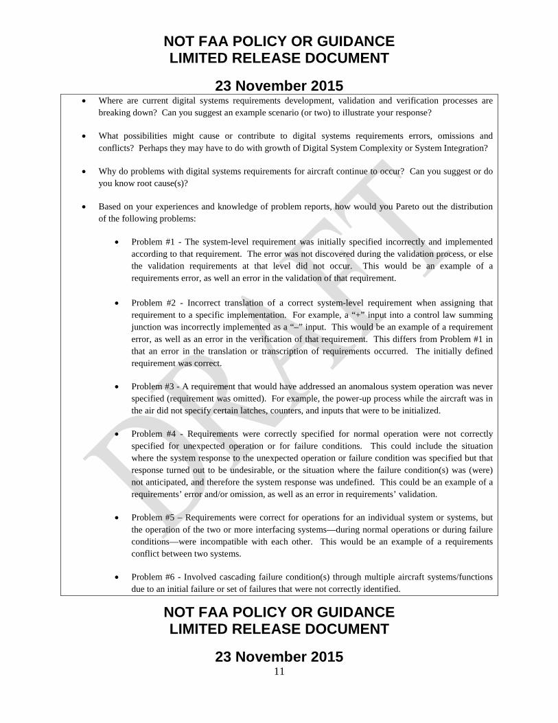
• Where are current digital systems requirements development, validation and verification processes are breaking down? Can you suggest an example scenario (or two) to illustrate your response?
• What possibilities might cause or contribute to digital systems requirements errors, omissions and conflicts? Perhaps they may have to do with growth of Digital System Complexity or System Integration?
• Why do problems with digital systems requirements for aircraft continue to occur? Can you suggest or do you know root cause(s)?
• Based on your experiences and knowledge of problem reports, how would you Pareto out the distribution of the following problems:
• Problem #1 - The system-level requirement was initially specified incorrectly and implemented according to that requirement. The error was not discovered during the validation process, or else the validation requirements at that level did not occur. This would be an example of a requirements error, as well an error in the validation of that requirement.
• Problem #2 - Incorrect translation of a correct system-level requirement when assigning that requirement to a specific implementation. For example, a “+” input into a control law summing junction was incorrectly implemented as a “–” input. This would be an example of a requirement error, as well as an error in the verification of that requirement. This differs from Problem #1 in that an error in the translation or transcription of requirements occurred. The initially defined requirement was correct.
• Problem #3 - A requirement that would have addressed an anomalous system operation was never
specified (requirement was omitted). For example, the power-up process while the aircraft was in the air did not specify certain latches, counters, and inputs that were to be initialized.
• Problem #4 - Requirements were correctly specified for normal operation were not correctly
specified for unexpected operation or for failure conditions. This could include the situation where the system response to the unexpected operation or failure condition was specified but that response turned out to be undesirable, or the situation where the failure condition(s) was (were) not anticipated, and therefore the system response was undefined. This could be an example of a requirements’ error and/or omission, as well as an error in requirements’ validation.
• Problem #5 – Requirements were correct for operations for an individual system or systems, but
the operation of the two or more interfacing systems—during normal operations or during failure conditions—were incompatible with each other. This would be an example of a requirements conflict between two systems.
• Problem #6 - Involved cascading failure condition(s) through multiple aircraft systems/functions
due to an initial failure or set of failures that were not correctly identified.

NOT FAA POLICY OR GUIDANCE LIMITED RELEASE DOCUMENT
23 November 2015
NOT FAA POLICY OR GUIDANCE LIMITED RELEASE DOCUMENT
23 November 2015 12
• Problem #7 - System-level requirements where designers did not correctly anticipate potential
flight crew actions. (Note: It is understood that the designers can never fully protect an airplane from doing something totally wrong or unexpected, particularly if it is not consistent with crew procedures or training).
• Problem #8 - All system-level requirements were initially complete and correct. However, a
change was made in a specific system, function, or sub-function that was not adequately analyzed in terms of impacts to another system or function.
• Problem #9 – Inadequate horizontal integration is conducted, resulting in interfacing systems not
being aware of design constraints that systems are imposing on each other.
• Problem #10 – Inadequate vertical integration is conducted during the development from aircraft to system to item. Errors are made as the parent requirements are decomposed and derived into lower level children requirements.
Note: this more of a qualitative assessment, in which you are assessing how percentage distribution for these problems. If you believe that there are additional types of problems which contribute to incorrect, incomplete, or missing requirements, please identify the additional scenario(s) and Pareto. The total of your percentages should equal 100%. Please note to focus on the primary contributors when making this assessment (and not secondary problems).
Considerations: As you respond to the above questions, consider what possibilities might cause or contribute to aircraft digital system requirements errors, omissions and conflicts? Perhaps they may have to do with growth of System Complexity or System Integration? Response: Please forward your input directly to Dan Fogarty. If you have any questions, please email or call Dan directly.
05
1015202530

NOT FAA POLICY OR GUIDANCE LIMITED RELEASE DOCUMENT
23 November 2015
NOT FAA POLICY OR GUIDANCE LIMITED RELEASE DOCUMENT
23 November 2015 13
Final Question: Any other concerns related to possible issues and shortcomings with the current process used by the commercial aviation industry regarding requirements definition, validation, and verification for aircraft digital system requirements? Please respond below: 3.1.2 Questionnaire Results.
The SME responses to the questionnaire are provided in the boxed paragraphs following each question.
• Where are current requirements development, validation and verification processes breaking down? Can you suggest an example scenario (or two) to illustrate your response? Observations
• Validating the completeness of requirements for new and novel systems. Especially where those systems are complicated.
• Improvements can be made in establishing plans that are enough (but not too complex) to generate unambiguous life cycle data. It is important to allocate the required resources to execute the plans.
• It is important to ensure that there are rigorous up-front development and validation processes/activities. • Excessive or exclusive reliance on review of requirements as a means of up-front validation. Peer
reviews are necessary, but not sufficient. They will catch only a limited set of errors. • Failure to recognize the inherently iterative nature of development. For example, requiring 100% of
content for interface control data, prior to any real design work. Some data can and should be captured as soon as possible, but other data (e.g., detailed BITE reports) cannot be fully defined and validated until lower-level design is underway.
• Lack of a uniform definition and training on what constitutes validation and what the expectations are, at each phase of design. The result is varying levels of coverage, and rigor during reviews, analysis, and test.
• There’s a very broad span of opinion and practice about what is the appropriate level of requirements definition and what should be defined as a requirement.
• Fidelity of highly integrated lab testing equipment and thoroughness of such test procedures. • It is important to clearly establish roles, responsibility, and authority. • Software is built on the assumption of hardware behavior. If the hardware doesn’t behave as expected,
there will be SW/AEH problems.
Examples
• Missed requirement resulted in later design change. Network gateway signals are used to enable dataloading of airplane systems. During the early development, the requirement for the need for certain signals to be gatewayed even when a switch was not known to have a valid configuration installed for its location on the aircraft, the requirement was missed for the need to gateway those

NOT FAA POLICY OR GUIDANCE LIMITED RELEASE DOCUMENT
23 November 2015
NOT FAA POLICY OR GUIDANCE LIMITED RELEASE DOCUMENT
23 November 2015 14
signals required to enable dataload when the network system was going through an update. If a network system upgrade service bulletin was incorrectly installed, the airplane would be grounded until preloaded spares could be added. (Note: this had no impact on safety; at no time were incorrect software configurations loaded. The effect would be an increase in the required maintenance times).
• A program used to generate takeoff performance numbers was noted to take an excessive amount of time to calculate on the test vehicle. It was discovered that the same behavior was noted in lab testing but the tester did not flag the problem because the pass / fail criteria of the test did not specify a time requirement for the calculation. It was taking 2.5 minutes to compute takeoff numbers.
• What possibilities might cause or contribute to requirements errors, omissions and
conflicts? Perhaps they may have to do with growth of System Complexity or System Integration? Observations
• Most commonly, these problems occur where multiple organizations and/or companies must develop requirements that work together to perform some functions while also operate independently to develop their other requirements. In essence, the team focus can sometimes be more immediately on what they need and less urgently on the coordinated activity.
• Change is another “environmental” consideration. What assumptions did the developer make about changes that happen around them? Can their system detect when they could be affected by a change? Do they understand LRU hardware/app software/airplane system/airplane compatibility issues that can arise when one or more parts change?
• Often due to insufficient system requirements, failure/lack of thorough reviews, insufficient domain knowledge.
• Requirement errors, omissions, etc., are merely the human factor. Requirement development and validation methods, and the recognized effort to define a correct, complete, and appropriate set of requirements haven’t always adjusted to the increased integration of the systems architectures.
• It is important to understand the fidelity of models/simulations being used. Examples
• It is important to consider environmental impacts such as SEU upset. This gets to a key question: how do you find out whether assumptions about changes in the environment are valid? Some questions to help drive out requirements: Is your hardware susceptible to SEE? What kinds of SEE is it susceptible to? Does your system design handle all of these effects? Have you assessed the secondary effects of your systems mitigation activities for SEE? What assumptions did the design make to manage redundancy? Have you assessed the secondary effects of your redundancy management actions?
• The simulations used to model the hydraulic system pressures were not accurate in a specific flight-test condition (outside the bounds of normal airplane operation). When the test vehicle performed a similar condition in flight, Engineering subsequently discovered that their hydraulic system pressure model was not accurate. After updating the model, it was shown that a system logic change was required to preclude the unnecessarily triggering of the subsystem.
• The ice detection system on the test vehicle was noted to display a transient failure during certain test maneuvers. The sensor probes were known to be sensitive to rapid changes in angle of attack or angle of sideslip. The corrections derived from analysis had not been fully tested in the wind tunnel due to technical and economic practicalities. The requirements to which the probes were designed did not

NOT FAA POLICY OR GUIDANCE LIMITED RELEASE DOCUMENT
23 November 2015
NOT FAA POLICY OR GUIDANCE LIMITED RELEASE DOCUMENT
23 November 2015 15
consider the extreme and prolonged maneuvering performed during flight testing. The filtering of parameters had to be re-evaluated to ensure no such erroneous behavior would occur within the normal envelope of operations expected in service. (Note: this occurred during cascaded stalls and sideslips (i.e., outside the normal airline operating environment).

NOT FAA POLICY OR GUIDANCE LIMITED RELEASE DOCUMENT
23 November 2015
NOT FAA POLICY OR GUIDANCE LIMITED RELEASE DOCUMENT
23 November 2015 16
• Why do problems with digital systems requirements for aircraft continue to occur? Can
you suggest or do you know root cause(s)?
Observations • Specification validation of interfaces between systems is frequently not executed in a way that is
commensurate with the inevitable evolutionary nature of this complex problem. It is common for instance to require complete definition of all interfaces in one or two iterations prior to the point in development where the systems function is defined sufficiently to allow for a complete definition.
• Problems can sometimes occur because the requirement is too prescriptive at the system/subsystem or higher. Having requirements that are too prescriptive can drive requirements changes/churn.
• Sometimes the requirement does not have the connection to the intent. As result, the requirements verification focuses on the letter of the law (instead of the spirit). This can be mitigated by capturing the intent as the requirements rationale or creating a parent requirement which clearly captures the intent.
• As traditionally federated systems move to integrated modular avionics architectures, it is important for systems to understand the digital domain. As systems start including a significant software component, it is important to understand some of the issues that digital processing can introduce (sampling artifacts, how significant digits are affected by error terms, etc.).
• It is important for the system designers to have a good understanding of the environment in which their system will be operating in.
Examples
• One system assumed that because the values they were keeping track of should be changing slowly that the digital behavior would also be immune to sampling artifacts. It turned out that some signals were transient and the low sampling rates would cause one copy to see the signal and another copy to miss it.
• Based on your experiences and knowledge of problem reports, how would you Pareto out
the distribution of the following problems:

NOT FAA POLICY OR GUIDANCE LIMITED RELEASE DOCUMENT
23 November 2015
NOT FAA POLICY OR GUIDANCE LIMITED RELEASE DOCUMENT
23 November 2015 17
Attempts to Pareto examples of problems along the lines of the questionnaire are not the correct way to look at the overall problem. Rather, the responses to the earlier questions provide the needed information.
• Any other concerns related to possible issues and shortcomings with the current process
used by the commercial aviation industry regarding requirements definition, validation, and verification for aircraft digital system requirements? Please respond below:
We did not receive any inputs to this question; however, SME input to prior questions addressed possible issues and shortcomings.
3.1.3 SME Questionnaire Findings.
These findings emphasize the importance of having validated, complete, and correct requirements as well as recognizing the iterative nature of requirements validation. The following is a summary of common trends offered by the SMEs that may help identify potential areas of improvement: • Improving the validation (completeness and correctness) of requirements, particularly for
new, novel, and/or complex systems.
• Recognizing the inherently iterative nature of development. Re-evaluating plans and requirements content predicated on a linear design process. For example, a linear design process may require 100% of the content for interface control data to be specified prior to any real design work. Some data can and should be captured as soon as possible, but other data (e.g., detailed Built-in Test Equipment, or BITE, reports) cannot be fully defined and validated until lower-level design is underway. Program management practices (including organizational structure) may need to evolve with the non-linear nature of developing highly complex, integrated digital systems.
• Optimizing level of detail for development of plans in a disciplined fashion.
• Optimizing level of technical oversight to ensure plans are executed in a disciplined fashion.
• Looking to the future as designs grow in complexity, consider prototyping to help with validating the completeness and correctness of requirements against preliminary design architectures. The prototyping process can augment the peer review process, which will remain necessary. (Prototype tools can include model-based design, simulation, and simulated distributed tests, particularly for integrating across multiple systems.)

NOT FAA POLICY OR GUIDANCE LIMITED RELEASE DOCUMENT
23 November 2015
NOT FAA POLICY OR GUIDANCE LIMITED RELEASE DOCUMENT
23 November 2015 18
• Providing a uniform definition and training approach on what constitutes validation and what the expectations are at each phase of the design. Without this in place, it is possible for varying levels of coverage and rigor during reviews, analysis, and test. In light of the growth of complexity and integration, there is a need to iterate to an integrated solution. An analogy is the spiral software process.
• Developing an optimum level of fidelity in highly integrated lab testing equipment and test procedure completeness to accelerate learning and reduce cost of problem discovery on the aircraft.
• Validating assumptions about the environment.
3.1.3.1 Systems Complexity and Systems Integration.
In order to achieve increased functionality and improved performance, systems architectures are becoming more centralized and automated, with avionics designers integrating more functions and capabilities that reflect new technologies and increasing customer expectations. As a result of the evolution of airplane architectures, airplane functions traditionally supported by individual systems may now be integrated on a common computing platform with a common communication infrastructure (e.g., IMA architecture). These architecture changes provide several benefits to the airlines, pilots, and passengers. Integrated architectures can result in a reduction in parts, wiring, and weight that directly relates to decreased maintenance costs and, in the case of weight, decreased fuel burn. Increased integration and high reliance on software can also create more flexibility when system changes are needed, reflecting new technologies and increasing customer expectations. Adoption of IMA architecture and new electrical designs are two significant changes in airplane systems architectures. Moving to IMA architecture and introducing more electrically powered systems help improve performance and reduce overall airplane weight, but these design decisions also greatly increase system interface complexity. For the IMA architecture, airplane functions traditionally supported in a federated manner are now integrated on a common platform. For example, the electrical system moved from a traditional centralized bus design to a remote distribution design. The benefits of the highly integrated systems architectures also come with a challenge: managing an order of magnitude increase in data traffic. Calculations that were once carried out in individual systems can now be executed in an IMA. Raw data is collected at the source, packaged, and sent to the IMA, processed, and the results are repackaged and sent to subscribers. (Detailed information about IMAs can be found in DO-297, “Integrated Modular Avionics

NOT FAA POLICY OR GUIDANCE LIMITED RELEASE DOCUMENT
23 November 2015
NOT FAA POLICY OR GUIDANCE LIMITED RELEASE DOCUMENT
23 November 2015 19
(IMA) Development Guidance and Certification Considerations.”) This type of architecture increases signal traffic and makes data networks more intricate. Data management challenges of these new architectures include ensuring the network meets all timing, latency, and bandwidth requirements, as an individual signal may now have to cross 5-10 nodes on its path from source to subscriber. The increased systems integration and complexity increases the importance of requirements development. Problems related to iterative integration generally do not occur for self-contained (federated) functions with little or no integration. The problems occur when multiple systems have to participate in an airplane function such as power-on scenarios, data load, and the like. (An expanded explanation of iterative integration is provided in section 3.1.3.4, “Sufficient Planning” of this report). To help mitigate integration issues later in the program, it would be very beneficial for new and novel systems (IMA, remote power distribution, etc.) to develop requirements for the other airplane systems on how to use these resource systems as one of their first priorities. This would need to cover nominal as well as failure scenarios. With new and novel systems, a preliminary recommendation is to first prioritize the integration requirements for other systems. Requirements development and validation methods, and the recognized effort to define a correct, complete, and appropriate set of requirements have not always adjusted to the more integrated systems architectures. Consider the following example: A supplier decides to implement using a multitasking operating system of their own design. Such a design requires certain implementation practices to work robustly. The engineer writing the high-level requirements and designing the architecture does not identify the shared resources and the behaviors that the tasks need to follow. The engineer reviewing the requirements does not spot the problem either. The design/code is reviewed at a module rather than an integrated level. There is no specific requirement attached to the desired behavior, so verification testing does not catch the problem until it is discovered later during lab integration testing. From a software process perspective (defined as taking a system specification and turning it into executable code), experience seems to indicate that industry is good at ensuring the code matches the specification. For example, the processes and execution are generally very good at ferreting out problems in which there is an incorrect translation of a correct systems-level requirement when assigning that requirement to a specific implementation. This type of problem would be least likely to occur during integration and flight test.

NOT FAA POLICY OR GUIDANCE LIMITED RELEASE DOCUMENT
23 November 2015
NOT FAA POLICY OR GUIDANCE LIMITED RELEASE DOCUMENT
23 November 2015 20
3.1.3.2 New/Novel Technology and/or New Environments.
Problems can arise when the engineers preparing the specification, and/or conducting V&V, are not familiar with the digital domain (even if they are familiar with the airplane function). Experience with the digital domain can be increasingly important. If the engineer does not foresee some of the issues that digital processing can introduce (sampling artifacts, how significant digits are affected by error terms, etc.), problems can occur during early testing. As another example, a system could assume that because the values being tracked should be changing slowly, the digital behavior would also be immune to sampling artifacts. Some signals can be transient and the low sampling rates would cause one copy to see the signal and another copy to miss it. If there was a better understanding, this problem could be mitigated and would not remain undiscovered until testing. The operating environment also needs to be considered. For example, the following questions would help ensure a more complete understanding of the operating environment and acceptable systems behavior: • Is the hardware susceptible to Single Event Effects (SEE)? • What kinds of SEE is it susceptible to? • Does the system design handle all of these effects? • Have secondary effects of the systems mitigation activities for SEE been assessed? • What assumptions did the design make to manage redundancy? • Have the secondary effects of the redundancy management actions been assessed? Change is another “environmental” consideration. What assumptions did the developer make about changes that happen with integrated systems and any new environments (High-Intensity Radiated Field, etc.)? Does the developer understand line replaceable unit hardware/application software/airplane system/airplane compatibility issues that can arise when one or more parts change?
3.1.3.3 Organizational Impediments.
There is not a single organizational structure that, by itself, mitigates requirement V&V issues. It is helpful if the organizational structure reflects the integrated nature of the product. It is important to clearly establish roles and responsibilities. Large-scale systems integration means ensuring that the entire “system” works. Integration problems, by definition, are usually outside the exclusive domain of a single organization. There are multiple ways in which this can be organized. For example, the following approach is one (but not the only) way in which this can be addressed:

NOT FAA POLICY OR GUIDANCE LIMITED RELEASE DOCUMENT
23 November 2015
NOT FAA POLICY OR GUIDANCE LIMITED RELEASE DOCUMENT
23 November 2015 21
• Propulsion integration team – responsible for all of the integration within propulsion systems.
• Systems integration team – responsible for all the integration with systems (e.g., flight controls, hydraulics, electrical).
• Interiors integration team – responsible for all the integration with interiors systems. • Airplane-level integration team – responsible for all the integration between Propulsion,
Interiors, and Systems. Most commonly, requirements problems occur when multiple organizations and/or companies must develop requirements that drive systems design to meet system/aircraft performance. Design teams can sometimes focus more immediately on what they need from an intrasystem perspective and less urgently on the integrated, coordinated activity. A preliminary recommendation is to have a systems integration organization that will proactively coordinate and validate that there is an integrated solution. Additionally, this system integration organization would lead efforts to ensure technical adequacy of requirements definition/validation, architecture refinement, interface control specification revision, and development assurance/requirements verification plans as they are revised during the course of iterative development. 3.1.3.4 Sufficient Planning.
Development assurance requires the following plans to be created: • Safety assessment. • Requirements capture. • Requirements validation. • Implementation verification. • Configuration management. • Process assurance. • Certification and regulatory authority coordination. There are two aspects that will improve the success of these plans: timing and level of detail. The earlier the plans are developed and integrated, the less chance there will be that any aspects of requirements definition and V&V will be missed. The levels of detail in the plans need to be sufficient to generate unambiguous life cycle data, allocate the required resources and time to execute the plans, and provide sufficient technical oversight of resources. Just as requirements continue to be developed, balanced, and refined during iterative integration into the complete

NOT FAA POLICY OR GUIDANCE LIMITED RELEASE DOCUMENT
23 November 2015
NOT FAA POLICY OR GUIDANCE LIMITED RELEASE DOCUMENT
23 November 2015 22
aircraft or system, the plans must be refined to match. The overlying jumps from architecture selection, to design, to modeling, to implementation must be reflected in the evolving plans. As iterative integration drives the complexity higher and emerging system characteristics impact existing requirements, continuing refinement of plans and requirements must be accomplished. (Note: Iterative integration includes the complex interactions, controls [such as configuration management], design refinements, design requirements, and the coalescence of requirements and system implementation that achieves successful aircraft/system development and operation.) The plans need to recognize the inherently iterative nature of development. For example, requiring 100% of content for interface control data, prior to any real design work, does not recognize the integrated nature. Some data can, and should, be captured as soon as possible. However, other data (e.g., detailed BITE reports) cannot be fully defined and validated until lower-level design is underway.
3.1.3.5 Published Industry Guidance and Procedures.
Advisory Circular (AC) 20-174 recognizes ARP4754A as an acceptable development assurance process. AC20-115 and AC20-152 invoke, respectively, DO-178 and DO-254. Development programs also typically have Issue Papers (IP). The ACs and IPs must be successfully addressed to achieve certification. Therefore, there can be no shortcuts. However, industry experience with actually implementing ARP4754A is somewhat limited. As the industry gains more experience and collects lessons learned, there will be more harmonization on its application (particularly for minor model programs). 3.1.3.6 Requirements Validation.
The impact of incomplete, incorrect, or missing requirements is well understood. The process of ensuring requirements are completely correct is not easy; intentionally not including requirements is not a contributing factor. One way to improve the difficult job of validation is to have uniform definition and training on what constitutes validation and what the expectations are at each phase of design. This can help ensure the proper level of coverage and rigor during reviews, analysis, and test. In addition, it is helpful to ensure that the entire life cycle and downstream operators are being considered during requirements validation. For example, a program used to generate takeoff performance numbers was noted to take an excessive amount of time to calculate on the test vehicle. The same behavior was noted in lab testing but the tester did not flag the problem because the pass/fail criteria of the test did not specify a time requirement for the calculation. (Note: This delayed timing effect had no safety impact and was fixed during the test program).

NOT FAA POLICY OR GUIDANCE LIMITED RELEASE DOCUMENT
23 November 2015
NOT FAA POLICY OR GUIDANCE LIMITED RELEASE DOCUMENT
23 November 2015 23
The existing processes point to traceability as a key method of ensuring requirements completeness. As an example, detailed traceability analyses could be conducted to look for missing requirements. Parent-child requirements relationships would be established, validated, and integrated in a tool such as Dynamic Object-Oriented Requirements System. As designs become more complex in the future, there are tools that could augment traceability, analyses, and peer reviews. Modeling and prototyping of the digital system provides an opportunity to improve integration. Modeling provides the ability early on to ask, “Is this how you want the system to behave?” The follow-on question, “Is this how the system behaves?” also must be asked. In addition, if the requirement does not have the connection to the intent, problems can occur. As result, the requirements verification focuses on the letter of the law (instead of the spirit). This can be mitigated, as needed, by capturing the intent as the requirements’ assumption/rationale or by creating a parent requirement that clearly captures the intent. This is equivalent to developing a missing system-level requirement from lower level technically detailed/derived requirements. One can consider grouping lower level requirements to give context and intent for integration into higher level requirements.
3.1.3.7 Requirements Implementation Verification.
It is important to establish properly scoped verification activities. In addition, it is important to have optimum fidelity of the integrated lab testing equipment and thorough test procedures. This will help accelerate finding problems early in the program. As an example, simulations that model a system may not be accurate in a specific condition (that is only accomplished during the flight test program and not seen in revenue service). Engineering initially believes it is limited only to the specific ground testing being performed. When the test vehicle performs a similar condition in flight, the subsystem is unnecessarily triggered. Engineering subsequently discovers that their system model is inaccurate for this flight-test condition. After updating the model, it is shown that a system logic change is required to preclude unnecessarily triggering the subsystem. This type of situation illustrates the important relationship between modeling, simulation, and test with respect to ensuring all elements are harmonized. By doing this, the flight test program helps verify that the airplane will support the performance of all functions relative to performance in revenue service.

NOT FAA POLICY OR GUIDANCE LIMITED RELEASE DOCUMENT
23 November 2015
NOT FAA POLICY OR GUIDANCE LIMITED RELEASE DOCUMENT
23 November 2015 24
3.2 EVALUATION OF REAL-WORLD SCENARIOS AND POSSIBLE REQUIREMENTS IMPACTS.
3.2.1 Candidate Requirements Issues and Potential Shortcomings.
This research evaluated each of the eight scenarios identified in White Paper #3 to determine which possibilities might cause or contribute to requirements errors, omissions, and conflicts. The eight scenarios were chosen, with input from Boeing SMEs, as representative occurrences illustrating possible problems with requirements definition and V&V processes. Multiple problem reports across multiple design disciplines and programs were considered by Boeing SMEs prior to down-selecting to the eight scenarios. Each possibility was considered on a standalone basis; that is, any of the eight scenarios could have one or more corresponding possibilities selected. The possibilities that might cause or contribute to requirements errors, omissions, and conflicts were considered as follows:
1. System complexity. Is the system too complex for the designer to understand how it is to
operate in normal conditions, failure conditions (including multiple failure conditions), and pilot unexpected actions, such that it is extremely difficult for the designer to fully specify the system?
2. Organizational impediments. Are there organizational impediments, such as a large number of design groups or companies involved in developing significant portions of the system or systems, which could contribute to requirements errors, omissions, or conflicts? Would these organizational impediments make it more difficult for the designers to understand how the system will operate separately and when integrated with other aircraft systems, including failure conditions and pilot unexpected actions, such that it would be extremely difficult for the designer to fully specify the system? While these organizations will be using current tools, processes, and the like, they will also be using tools and processes unique to different organizations. This can raise the question of whether the lack of integrability of organization-unique toolsets and processes may be part of the requirements shortcoming. Integration conversations and hand-offs between OEMs and suppliers are very important to ensure design integrity. This takes precedence over common tools. There is also an increased ability in recent years to share data across different toolsets, thus reducing the potential problems in this area. Achieving tool commonality across the aviation industry would be a very challenging task.
NOT FAA POLICY OR GUIDANCE LIMITED RELEASE DOCUMENT
23 November 2015
NOT FAA POLICY OR GUIDANCE LIMITED RELEASE DOCUMENT
23 November 2015 25
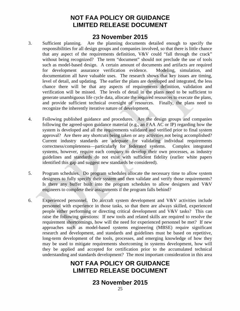
3. Sufficient planning. Are the planning documents detailed enough to specify the responsibilities for all design groups and companies involved, so that there is little chance that any aspect of the requirements definition, V&V could “fall through the crack” without being recognized? The term “document” should not preclude the use of tools such as model-based design. A certain amount of documents and artifacts are required for development assurance verification evidence. Modeling, simulation, and documentation all have valuable uses. The research shows that key issues are timing, level of detail, and updating. The earlier the plans are developed and integrated, the less chance there will be that any aspects of requirements definition, validation and verification will be missed. The levels of detail in the plans need to be sufficient to generate unambiguous life cycle data, allocate the required resources to execute the plans, and provide sufficient technical oversight of resources. Finally, the plans need to recognize the inherently iterative nature of development.
4. Following published guidance and procedures. Are the design groups and companies
following the agreed-upon guidance material (e.g., an FAA AC or IP) regarding how the system is developed and all the requirements validated and verified prior to final system approval? Are there any shortcuts being taken or any activities not being accomplished? Current industry standards are adequate for validating individual requirements correctness/completeness—particularly for federated systems. Complex integrated systems, however, require each company to develop their own processes, as industry guidelines and standards do not exist with sufficient fidelity (earlier white papers identified this gap and suggest new standards be considered).
5. Program schedules. Do program schedules allocate the necessary time to allow system designers to fully specify their system and then validate and verify those requirements? Is there any buffer built into the program schedules to allow designers and V&V engineers to complete their assignments if the program falls behind?
6. Experienced personnel. Do aircraft system development and V&V activities include personnel with experience in those tasks, so that there are always skilled, experienced people either performing or directing critical development and V&V tasks? This can raise the following questions: If new tools and related skills are required to resolve the requirement shortcomings, how will the need for experienced personnel be met? If new approaches such as model-based systems engineering (MBSE) require significant research and development, and standards and guidelines must be based on repetitive, long-term development of the tools, processes, and emerging knowledge of how they may be used to mitigate requirements shortcoming in systems development, how will they be applied and accepted for certification prior to the accumulated technical understanding and standards development? The most important consideration in this area
NOT FAA POLICY OR GUIDANCE LIMITED RELEASE DOCUMENT
23 November 2015
NOT FAA POLICY OR GUIDANCE LIMITED RELEASE DOCUMENT
23 November 2015 26
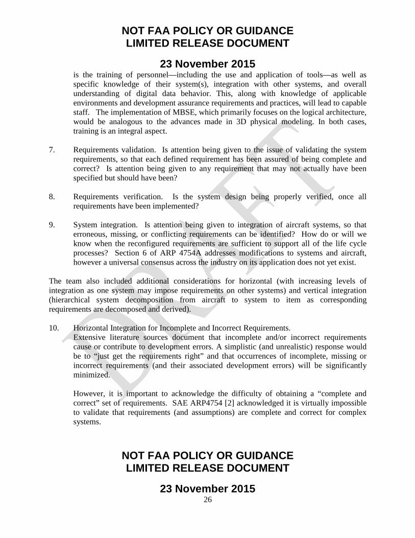
is the training of personnel—including the use and application of tools—as well as specific knowledge of their system(s), integration with other systems, and overall understanding of digital data behavior. This, along with knowledge of applicable environments and development assurance requirements and practices, will lead to capable staff. The implementation of MBSE, which primarily focuses on the logical architecture, would be analogous to the advances made in 3D physical modeling. In both cases, training is an integral aspect.
7. Requirements validation. Is attention being given to the issue of validating the system requirements, so that each defined requirement has been assured of being complete and correct? Is attention being given to any requirement that may not actually have been specified but should have been?
8. Requirements verification. Is the system design being properly verified, once all requirements have been implemented?
9. System integration. Is attention being given to integration of aircraft systems, so that erroneous, missing, or conflicting requirements can be identified? How do or will we know when the reconfigured requirements are sufficient to support all of the life cycle processes? Section 6 of ARP 4754A addresses modifications to systems and aircraft, however a universal consensus across the industry on its application does not yet exist.
The team also included additional considerations for horizontal (with increasing levels of integration as one system may impose requirements on other systems) and vertical integration (hierarchical system decomposition from aircraft to system to item as corresponding requirements are decomposed and derived). 10. Horizontal Integration for Incomplete and Incorrect Requirements.
Extensive literature sources document that incomplete and/or incorrect requirements cause or contribute to development errors. A simplistic (and unrealistic) response would be to “just get the requirements right” and that occurrences of incomplete, missing or incorrect requirements (and their associated development errors) will be significantly minimized.
However, it is important to acknowledge the difficulty of obtaining a “complete and correct” set of requirements. SAE ARP4754 [2] acknowledged it is virtually impossible to validate that requirements (and assumptions) are complete and correct for complex systems.

NOT FAA POLICY OR GUIDANCE LIMITED RELEASE DOCUMENT
23 November 2015
NOT FAA POLICY OR GUIDANCE LIMITED RELEASE DOCUMENT
23 November 2015 27
When requirements changes result in late design changes, it adversely affects cost, schedule, and, potentially, safety. There is a vested interest throughout the aviation industry to have complete and correct requirements. However, that is easier said than done. No one intentionally has incorrect or incomplete requirements. There are a number of situations where late design changes can impact the product development life cycle from design through certification and into service operation. These include:
• Requirements addressing timing and resource allocation. Development of system
architecture, functionality, design, and component selection can result in changes to these requirements as the reality of the system/aircraft resources to be shared becomes more defined. Multiple allocations on specific resources (e.g., bandwidth on communications networks, computer processing priorities, and time, power, and weight allocations) can result in competition for available resources.
• Measurement and evaluation of the implemented system(s) may result in resources
(or use of resources) that do not achieve, or overuse, the expected, required, or advertised resource levels.
• Emerging characteristics of the aircraft/system may reveal limitations that were not
foreseen during the design process and can result in derived requirements and the possibility of additional or modified system level requirements.
• Additions of new requirements or changes to existing requirements including
additional requirements identified during the aircraft development can exacerbate the competition for available resources.
• Even the addition of resources due to component selection, design, or architecture
changes can reverberate through the requirements and initiate ripples of requirements change. This may include additional functionality or the addition of new requirements justified by the growth of shared resources. Multiple domain organizations within the system/aircraft development/integration may simultaneously try to take advantage of the added resources.
This suggests that a change impact analysis be conducted in light of the iterative process of requirements changes and additions (note content regarding the importance of recognizing the iterative nature of requirements validation in section 3.1.3, SME Questionnaire Findings, of this report).
Many of the existing guidelines focus on validating the existing requirements set. There are rather extensive guidelines on different methods for validating the completeness and

NOT FAA POLICY OR GUIDANCE LIMITED RELEASE DOCUMENT
23 November 2015
NOT FAA POLICY OR GUIDANCE LIMITED RELEASE DOCUMENT
23 November 2015 28
correctness of requirements (e.g., recommended validation matrix questions or attributes). However, there is not a significant amount of industry guidance on how to identify “missing” requirements. To a certain extent, this becomes axiomatic. If the requirement were known, it would be captured and communicated. However, if the requirement is unknown, it is difficult to capture. There are techniques for analyzing existing requirements to evaluate completeness and accuracy. For example, requirements can be linked by organizational responsibility, functionality, architecture allocations, resources, verification methods, system requirements (decomposition), and derived requirements (including synthesis).
Even with existing requirements, the potential exists for the requirement to be misinterpreted or misunderstood. Because most requirements are text-based, there is always the possibility that two people will read it and reach different conclusions (i.e., they are “not on the same page”). This is one reason why requirements reviews exist. It is also the reason for the use of logical annotation languages and related tools for architectural design, system design, requirements’ engineering analyses, executable modeling language, simulation languages, and related tools. There are additional possibilities for applying consistency checking with these tools and techniques.
Figure 2 shows a simplistic example in which a Flight Management System expert develops requirements, which, to the best of the individual’s ability, reflect a complete and correct set of requirements. This information is passed to the Flight Management software engineer, who develops the Flight Management software.
Figure 2. Abstraction/Mental Model to Software
The following steps are involved:
• Capture • Communicate • Comprehend

NOT FAA POLICY OR GUIDANCE LIMITED RELEASE DOCUMENT
23 November 2015
NOT FAA POLICY OR GUIDANCE LIMITED RELEASE DOCUMENT
23 November 2015 29
If there are any gaps in terms of capturing, communicating, or comprehending the requirements, it will increase the chance that requirements will be missed or misinterpreted. With the increasing level of integration between aircraft functions and the systems that implement them (figure 3), one system may impose requirements on other systems (e.g., performance, design constraints). If this is not done correctly, it can increase the possibility of a development error.
Figure 3. Integrated Systems
Figure 3 is a simplistic example to show requirements interrelationships in the systems engineering domain and does not attempt to show resource interrelationships in the architecture/design domain. It is not meant to imply that one system imposing requirements on other systems covers the entire spectrum. For example, system resources may be shared with multiple system functions/systems/subsystems. Requirements controlling resource behavior must be shared with all users of those resources. The design activities must be aware of this and establish derived lower level requirements in cognizance of system architecture, design, and their relationship with system-level requirements (both existing and the additional system-level requirements that must be created to achieve complete and accurate requirements).
11. Vertical Integration for Incomplete and Incorrect Requirements.
In addition to needing to understand the “horizontal integration,” there is also a need to understand the “vertical integration.”

NOT FAA POLICY OR GUIDANCE LIMITED RELEASE DOCUMENT
23 November 2015
NOT FAA POLICY OR GUIDANCE LIMITED RELEASE DOCUMENT
23 November 2015 30
As shown in figure 4, the development assurance processes are defined from a hierarchical system decomposition, going from aircraft to system to item. At each level, requirements are decomposed and derived. Higher-level parent requirements are decomposed into lower-level children requirements. In addition, some requirements may be derived directly from design decisions and are not directly traceable to higher level requirements.
Safety analyses are conducted at each respective level, resulting in derived safety requirements.
If there are any errors or omissions at the higher level, these can manifest in lower levels, resulting in undesirable or unpredicted behavior.

NOT FAA POLICY OR GUIDANCE LIMITED RELEASE DOCUMENT
23 November 2015
NOT FAA POLICY OR GUIDANCE LIMITED RELEASE DOCUMENT
23 November 2015 31
Figure 4. Vertical Integration of Requirements
DO-178 [5] and DO-254 [6] assume that a complete and correct set of requirements have been allocated to the software and airborne electronic hardware. The interactions between different systems, if not properly understood, can be a source of problems.

NOT FAA POLICY OR GUIDANCE LIMITED RELEASE DOCUMENT
23 November 2015
NOT FAA POLICY OR GUIDANCE LIMITED RELEASE DOCUMENT
23 November 2015 32
3.2.2 Selected Real-World Avionics Scenarios and Detailed Analyses.
The following subsections detail research findings for each of the real-world scenarios. 3.2.2.1 Scenario #1.
In Scenario #1, the system-level requirement was initially specified incorrectly and implemented according to that requirement. The error was not discovered during the validation process, or else the validation requirements at that level did not occur. This would be an example of a requirements error, as well an error in the validation of that requirement. An example is the transition time for the handshake between two systems. The requirement was reviewed by SMEs. They were knowledgeable and believed the requirement to be correct. However, during testing, it was determined that the handshake time between the two systems was too long and was adjusted accordingly.
3.2.2.1.1 Findings. There was a requirement for the transition time for the handshake between Primary Flight Controls and Autopilot. As part of the requirements validation process, the content of the requirement was reviewed by the SMEs, who were knowledgeable and determined the handshake time requirement to be correct. The requirement was then baselined, allowing the design, build, and verification process to proceed for this system. As part of the overall verification process, a test matrix was developed that included both nominal and off-nominal cases. One of the off-nominal cases—single engine out testing on an upward sloping runway—showed that the handshake time requirement was too long. It should be noted that this condition was very unique to the flight-testing regime. During flight test programs, profiles are flown which are outside of normal operations in order to gather data and test conditions that will not be experienced by operational airlines. For example, data can be collected for conditions beyond the normal operational boundaries to validate behavior. By doing this, the flight test program helps verify that the airplane will support the performance of all functions relative to performance in revenue service. Source data for this scenario included SME interviews, BCA product development flight squawks, and problem reports. This scenario highlights the potential need for additional industry guidance in the following area: Examination of processes to ensure that OEMs and suppliers are working to a complete and correct set of requirements to the greatest practical extent.
NOT FAA POLICY OR GUIDANCE LIMITED RELEASE DOCUMENT
23 November 2015
NOT FAA POLICY OR GUIDANCE LIMITED RELEASE DOCUMENT
23 November 2015 33
3.2.2.2 Scenario #2. Scenario #2 involved incorrect translation of a correct system-level requirement when assigning that requirement to a specific implementation. For example, a “+” input into a control-law summing junction was incorrectly implemented as a “–” input. This would be an example of a requirement error, as well as an error in the verification of that requirement. This differs from Scenario 1 in that an error in the translation or transcription of requirements occurred. The initially defined requirement was correct. A bug was introduced by way of a coding error when a data field was used without initialization. The data field was associated with the number of flights between operational tests. The data field is typically initialized when a system test is performed, but not otherwise. When a new software data load is performed to update the equipment, the field is not initialized. The coding error was in using an uninitialized space. Errors like this are typically discovered during peer reviews and testing. Consistency checking and automated removal of the problem without the possibility of human error in peer reviews is also a possible approach. 3.2.2.2.1 Findings. The software made by one supplier had a bug introduced into it through a coding error where a data field—associated with the number of flights between operational tests—was used without initialization. This data field is initialized when a system test is performed but not otherwise. When a new software data load was performed to update the equipment, this field was not initialized. This was really a two-part error. The first part was to make the coding error of using uninitialized space. This escaped software-level verification testing since the sequence of testing would have included a step that did the proper initialization. The second error was the decision to fail the system when the counter reached a certain value. The correct action should have been to annunciate the condition but continue to operate. The software was peer reviewed by the supplier and approved by the supplier. In further investigation to successfully resolve the problem report, it was validated that the requirements were complete and correct; the software needed to be modified. Source data for this scenario included SME interviews, test squawks, and problem reports. This scenario highlights the potential need for additional industry guidance in the following area:

NOT FAA POLICY OR GUIDANCE LIMITED RELEASE DOCUMENT
23 November 2015
NOT FAA POLICY OR GUIDANCE LIMITED RELEASE DOCUMENT
23 November 2015 34
• Identify potential gaps that may exist with processes to validate and verify requirements for both single-system/function and intersystem/cross-function levels, including pilot evaluation of aircraft-level operation.
3.2.2.3 Scenario #3. In Scenario #3, a requirement that would have addressed an anomalous system operation was never specified. For example, the power-up process while the aircraft was in the air did not specify certain latches, counters, and inputs that were to be initialized. On 1 August 2005, at 1703 Western Standard Time, a Boeing 777-200 operated by Malaysian Airline System, experienced a pitch up about 30 min after takeoff from Perth, Australia, while climbing through 36,000 ft with autopilot on. During the pitch up, the aircraft climbed to 41,000 ft and the indicated airspeed dropped from 270 knots to 158 knots. The stick shaker and the stall warning indicator activated during the event. The flight landed uneventfully back at Perth. In June 2001, accelerometer #5 failed with erroneous high output values. The air data inertial reference unit (ADIRU) disregards the accelerometer output values. The power cycle on the ADIRU occurs on each occasion the aircraft electrical system is shut down and restarted. In August 2005, accelerometer #6 fails. The latent software anomaly allows use of the previously failed accelerometer #5 output. The result is the in-flight upset. On 29 August 2005, the FAA issued emergency AD 2005-18-51 [9] to install ADIRU-03 software, stating that faulty ADIRU data could cause anomalies in 777 primary flight controls, autopilot, pilot displays, autobrakes, and autothrottles. A contributing safety factor was an anomaly that permitted inputs from a known faulty accelerometer to be processed by the ADIRU and used by other aircraft systems, including the primary flight computer and autopilot. [10]
3.2.2.3.1 Findings. The ADIRU software was DO-178B compliant. The anomaly in the original ADIRU software, which allowed inputs from a known faulty accelerometer to be processed by the ADIRU and used by the flight computer, autopilot and other aircraft systems, was not detected during testing. Accelerometer #5 failed with erroneous high output values. The ADIRU software disregarded the erroneous high output value from accelerometer #5; it was programmed to use the values

NOT FAA POLICY OR GUIDANCE LIMITED RELEASE DOCUMENT
23 November 2015
NOT FAA POLICY OR GUIDANCE LIMITED RELEASE DOCUMENT
23 November 2015 35
from backup systems. However, the restart of the ADIRU masked the initial failure of accelerometer #5; the power cycle on the ADIRU occurs on each occasion the aircraft electrical system is shut down and restarted. In addition, a latent software error that allowed the ADIRU to use input of an accelerometer had failed. When accelerometer #6 failed, the previously failed accelerometer #5 output was used, resulting in the in-flight upset. This scenario highlights the potential need for additional industry guidance in the following areas: • Examine processes to ensure that OEMs and suppliers are working to a complete and
correct set of requirements to the greatest practical extent.
• Identify potential gaps that may exist with processes to validate and verify requirements for both single-system/function and intersystem/cross-function levels, including pilot evaluation of aircraft-level operation.
• Evaluate failure conditions on system functions and assurance of requirements to resolve undesirable combinations affecting aircraft/system performance.
3.2.2.4 Scenario #4. Scenario #4 involved requirements that were correctly specified for normal operation but were not correctly specified for unexpected operation or for failure conditions (either single or multiple). This could include the situation where the system response to the unexpected operation or failure condition was specified but that response turned out to be undesirable, or the situation where the failure condition (or conditions) was (were) not anticipated, and therefore the system response was undefined. This could be an example of a requirements error and/or omission, as well as an error in requirements validation. An example is pump reservoir rise/fall due to a dip in pump speed resulting from long power interrupts. Long power interrupts lead to dips in pump speed that cause a momentary rise/fall of the pump reservoir, with corresponding dips in pump current and loop pressure. The falling edge of the transient in the reservoir position is quick enough to initiate the leak detection/isolation logic, leading to nuisance leak indications. 3.2.2.4.1 Findings. Based on interviews with Boeing design SMEs and requirements experts, and reviews of problems reports, it was determined that this scenario can occur when either the required resolution and/or required tolerance are not properly specified. This can become a problem in
NOT FAA POLICY OR GUIDANCE LIMITED RELEASE DOCUMENT
23 November 2015
NOT FAA POLICY OR GUIDANCE LIMITED RELEASE DOCUMENT
23 November 2015 36
normal operations. It becomes even more of a problem if the required resolution and/or required tolerance is not specified for unexpected operations or failure conditions. This scenario highlights the importance of considering off-nominal and failure modes as a critical part of requirements V&V. Source data for this scenario included SME interviews, test squawks, and problem reports. This scenario highlights the potential need for additional industry guidance in the following areas: • Investigate processes to help identify missing requirements during the requirements
validation phase, particularly those related to horizontal integration.
• Examine processes to ensure that OEMs and suppliers are working to a complete and correct set of requirements to the greatest practical extent.
• Consider potential process improvements to address cumulative effects of otherwise
acceptable individual systems-level cascading effects. 3.2.2.5 Scenario #5. Scenario #5 involved requirements that were correct for operations for an individual system or systems, but the operation of the two or more interfacing systems—during normal operations or during failure conditions—were incompatible with each other. This would be an example of a requirements conflict between two systems. This scenario covers cases where the requirements are correct from a federated systems perspective, but not from an integration perspective. This scenario can result in causing problems for interfacing systems (particularly in the presence of failures) and usually occurs during design changes. For example, if a system makes a design change to its voting algorithm, its effects would need to be understood and clearly communicated to other systems.
NOT FAA POLICY OR GUIDANCE LIMITED RELEASE DOCUMENT
23 November 2015
NOT FAA POLICY OR GUIDANCE LIMITED RELEASE DOCUMENT
23 November 2015 37
3.2.2.5.1 Findings. Based on interviews with Boeing design SMEs and requirements experts, and reviews of problems reports, it was determined that this scenario can also occur when the required resolution and/or required tolerance are not properly specified, particularly from an integration perspective. This can sometimes happen when changes are made to a voting algorithm. For example, if a system changes its voting algorithm to make its data invalid based on a +/- tolerance of 10° C, it will cause problems if an interfacing system is expecting data to be invalid if the tolerance is +/- 1 degree from the agreed upon constraint. There are several reasons why this can occur. If the requirements are not validated to be complete and correct, then problems can occur. In addition, there can be problems from both a horizontal and vertical integration perspective. Some of the required tolerances may be in place to support safety analyses. If the vertical integration and requirements traceability is missing, there is the possibility that the key requirements will not be identified. As a result, an interfacing system may change its tolerance without understanding the impact on other systems. If the horizontal integration is not adequately performed, then the interfacing systems will not be aware of the required constraints the systems are imposing on each other. Source data for this scenario included SME interviews, test squawks, and problem reports. This scenario highlights the potential need for additional industry guidance in the following areas: • Examine processes to ensure that OEMs and suppliers are working to a complete and
correct set of requirements to the greatest practical extent.
• Identify potential gaps that may exist with processes to validate requirements for both single-system/function and intersystem/cross-function levels, including pilot evaluation of aircraft-level operation.
• Consider establishing an approach to validate and verify intrasystem functionality to determine that proper function, content, and performance exist.
− Include consideration of intersystem functionality verification.
− Include consideration of aircraft-level failure modes and effects.
• Investigate the potential need to improve horizontal and vertical integration for V&V processes at the component, intrasystem, intersystem, and airplane levels.

NOT FAA POLICY OR GUIDANCE LIMITED RELEASE DOCUMENT
23 November 2015
NOT FAA POLICY OR GUIDANCE LIMITED RELEASE DOCUMENT
23 November 2015 38
3.2.2.6 Scenario #6. Scenario #6 involved cascading failure conditions through multiple aircraft systems or functions due to an initial failure or set of failures were not correctly identified. This would be an example of the requirements for multiple systems not having been adequately validated, or possibly a requirements conflict between two or more aircraft systems. As systems architectures become more integrated, many systems functions that were typically separated with limited interdependence are now interrelated and highly integrated. The possibility exists that certain failure modes, which in a federated system may have limited effect on other systems, may now have cascading effects on other systems. It is important to validate that the flight crew will be able to cope with failures that result in multiple flight deck effects. Integration analyses and testing are necessary to validate the acceptability of failure modes, which may result in the following flight deck effects:
• Highly integrated (e.g., Integrated Modular Avionics system, Electrical System, and
others) unit failures that cause multiple, confusing, or cascading effects, alerts, unusable electronic checklists. (For existing related regulations, reference CFR 25.1302 and 25.1322, which addresses precedence of warning, cautions, and advisories and applicable crew actions for each).
• Burying time-sensitive alerts.
• Display loss or inappropriate reversions.
• Cascading effects from “simple” single failures, e.g., generator.
• Loss of crew alerting.
• Inability of crew to find correct checklist.
Boeing developed processes to address gaps in existing industry guidelines. The cascading failure analyses support validation that the systems architecture integration on the airplane meets the airplane-level safety requirements. The implementation of Boeing’s processes identified requirements changes, design changes (including software changes), wiring changes, crew procedure changes, and test changes. Boeing does not believe that it would have identified these required changes if it had simply followed ARP4754A and ARP4761. From the March 2011 issue of Boeing’s Frontiers magazine (Volume XI, Issue X), Chief Project Engineer Mike Sinnett described one of the tests that validated the cascading failure analyses:
NOT FAA POLICY OR GUIDANCE LIMITED RELEASE DOCUMENT
23 November 2015
NOT FAA POLICY OR GUIDANCE LIMITED RELEASE DOCUMENT
23 November 2015 39
Sinnett described one particularly challenging test that demonstrates the overall robustness of the 787 design and its capability to maintain safe conditions in the presence of multiple failures. “We intentionally failed one of the three air-data systems that provide key information on speed and altitude,” Sinnett explained. “After that, we caused the remaining two systems to disagree.” When the two remaining systems disagree, it means there is no known valid source of speed and altitude data. That is when the backup systems kick in. “Pilots see an annotation that they are getting this information from backup systems, but they never lose data on the primary flight display,” Sinnett continued. Altitude is provided from the GPS system. Known conditions from a variety of systems and inputs, including aircraft gross weight, angle of attack, high-lift configuration and other parameters, allow the airplane to back-calculate airspeed from the lift equation and display it on the flight deck. “This represents a significant advancement in safety and crew awareness in the presence of multiple failures,” he said. [11]
3.2.2.6.1 Findings. The example above provides a “positive” example (as opposed to a “negative” example, which is discovered as a problem report). It also emphasizes the importance of having good intrasystem, intersystem, and failure analyses to validate the systems architecture. Requirements are an integral part of the design process. However, it is also important to conduct the systems architectural analyses. Doing so can help validate that the requirements are complete and correct. Source data for this scenario included SME interviews, test squawks, and problem reports. This scenario highlights the potential need for additional industry guidance in the following areas: • Identify potential gaps that may exist with processes to validate requirements for both
single-system/function and intersystem/cross-function levels, including pilot evaluation of aircraft-level operation.
• Consider establishing an approach to validate and verify intrasystem functionality to determine that proper function, content, and performance exist.
− Include consideration of intersystem functionality verification.
− Include consideration of aircraft-level failure modes and effects.

NOT FAA POLICY OR GUIDANCE LIMITED RELEASE DOCUMENT
23 November 2015
NOT FAA POLICY OR GUIDANCE LIMITED RELEASE DOCUMENT
23 November 2015 40
• Investigate potential process improvements to facilitate requirements validation for the modification of existing systems.
• Investigate the potential need to improve horizontal and vertical integration for V&V processes at the component, intrasystem, intersystem, and airplane levels.
• Consider potential process improvements to address cumulative effects of otherwise acceptable individual systems-level cascading effects.
3.2.2.7 Scenario #7. Scenario #7 involved system-level requirements that did not correctly anticipate flight crew actions or responses to specific conditions or failures. This scenario covers a deliberate action by the flight crew that was not necessarily anticipated by the system designers. (Note: It is understood that the designers can never fully protect an airplane from doing something totally wrong or unexpected, particularly if it is not consistent with crew procedures or training). For example, an autopilot design did not anticipate the flight crew making control inputs into the flight control system without first disconnecting the autopilot. On 13 July 1996, a McDonnell Douglas MD-11 experienced an in-flight upset near Westerly, Rhode Island. On 8 June 1997, a different MD-11 experienced an in-flight upset near Nagoya, Japan. Per National Transportation Safety Board (NTSB) Recommendations A-99-39-44 [12], these in-flight upsets were caused when the flight crewmembers made manual flight control inputs while the autopilot system was engaged. The pilots, per the airplane flight manual, should not have made manual flight control inputs when the autopilot is engaged. Doing so will result in a sudden and abrupt movement of some flight control surfaces; when the autopilot disengages, there will be an unpredictable airplane response. In both in-flight upsets, the crew members took actions that they believed were appropriate to address their concerns (in one case, concern that the airplane might not level off at assigned altitude, creating need to slow rate of descent; in the other case, concern that the airplane would accelerate beyond the maximum operating airspeed). However, in both cases, the crewmembers made manual control inputs prior to disengaging the autopilot. The NTSB recommendations ranged from revising airplane flight manuals/company flight manuals to improve awareness to requiring all new transport-category airplane autopilot systems to be designed to prevent flight upsets when manual inputs to the flight controls are made. [12]
NOT FAA POLICY OR GUIDANCE LIMITED RELEASE DOCUMENT
23 November 2015
NOT FAA POLICY OR GUIDANCE LIMITED RELEASE DOCUMENT
23 November 2015 41
3.2.2.7.1 Findings. The autopilot was designed with the assumption that the flight crew would not provide manual inputs when the autopilot was engaged. The airplane flight manual directed that this should not occur. However, pilots did provide manual inputs with the autopilot engaged. System complexity was determined to be the key contributing factor for the example above. It was not necessarily the system complexity of the system by itself. It was the broader aspect of system complexity that considers how the system operates in both normal and failure conditions and unexpected flight crew actions. [12] This scenario highlights the importance and challenges with considering potential pilot unexpected actions. It is not possible to consider all potential unexpected pilot actions (e.g., not following training associated with the required crew procedures for an annunciated message). It is also expected that the crewmembers will follow established procedures. A possible area for future research is the design of systems that interface with humans to monitor the human-machine interface and respond to inputs not within the boundaries of normal operations. This scenario highlights the potential need for additional industry guidance in the following areas: • Investigate processes to help identify missing requirements during the requirements
validation phase.
• Identify potential gaps that may exist with processes to validate requirements for both single-system/function and intersystem/cross-function levels, including pilot evaluation of aircraft-level operation.
3.2.2.8 Scenario #8. In Scenario #8, all system-level requirements were initially complete and correct. However, a change was made in one area, such as a specific aircraft system, function, or sub-function, and that change was not adequately analyzed so that the change adversely affected the operation of another aircraft system or function. This would be an instance of a requirements conflict. Additionally, this is an instance of the system-level change impact analysis (CIA) not being performed completely or correctly. These results are sometimes referred to as “change on change.” After a change is implemented in one system, it has unanticipated, unexpected effects on other systems, resulting in the need to drive additional changes. Having a robust CIA is the best way to mitigate this issue. In general,

NOT FAA POLICY OR GUIDANCE LIMITED RELEASE DOCUMENT
23 November 2015
NOT FAA POLICY OR GUIDANCE LIMITED RELEASE DOCUMENT
23 November 2015 42
this tended to happen when there was a subtlety in the design change implementation that was not clearly understood by all impacted systems’ teams. 3.2.2.8.1 Findings. After interviews with requirements management SMEs and change/configuration management experts, it was determined the key contributing factor that causes this scenario is the increased systems complexity. As systems become more highly integrated, the impact of a change on other systems may not be readily apparent without a rigorous CIA. Some key areas to consider as part of the CIA include the impact on: • Functionality. • Performance. • Interfaces (particularly with other systems). • Safety analyses. • Resource utilization. • Emerging system behavior. If the cross-functional impact is not considered when changes are implemented, it is possible that there will be a subsequent “change on changes.” This can occur when proper consideration is not given to the cross-functional impact of a given change. The change fixes the original problem; however, the change now also introduces new problems, precipitating the need for another change. Source data for this scenario included SME interviews, test squawks, and problem reports. This scenario highlights the potential need for additional industry guidance in the following areas: • Examine processes to ensure that OEMs and suppliers are working to a complete and
correct set of requirements to the greatest practical extent.
• Identify potential gaps that may exist with processes to validate requirements for both single-system/function and intersystem/cross-function levels, including pilot evaluation of aircraft-level operation.
• Consider establishing an approach to validate and verify intersystem functionality to determine that proper function, content, and performance exist. This would include resource utilization and emerging system behavior.
− Include consideration of intersystem functionality verification.
NOT FAA POLICY OR GUIDANCE LIMITED RELEASE DOCUMENT
23 November 2015
NOT FAA POLICY OR GUIDANCE LIMITED RELEASE DOCUMENT
23 November 2015 43
− Include consideration of aircraft-level failure modes and effects.
• Investigate potential process improvements to facilitate requirements validation for the modification of existing systems.
3.2.3 Integration of Real-World Avionics Scenarios and SME Questionnaire Responses.
A comparison of SME questionnaire responses (outlined in section 3.1.2) and findings for potential additional guidance for each of the real-world avionics scenarios (outlined in section 3.2.2) was made to look for common elements as listed in figure 5 (with paraphrased content from sections 3.1.2 and 3.2.2). Evaluation of this comparison suggests: • The predominant common element between SME responses and potential additional
guidance was in the area of working to a complete and correct set of requirements.
• Another significant common element was identifying missing requirements.
• A third element that was emphasized by this comparison was identifying potential gaps that may exist with processes to validate and verify requirements.
Each of these common elements aligned to multiple inputs from the SMEs as well as multiple real-world scenarios. In addition, these common elements align with incomplete, incorrect, or missing requirements as a major root-cause category of requirements’ issues and shortcomings listed in section 3.3 of this report.

NOT FAA POLICY OR GUIDANCE LIMITED RELEASE DOCUMENT
23 November 2015
NOT FAA POLICY OR GUIDANCE LIMITED RELEASE DOCUMENT
23 November 2015 44
SME Question Questionnaire Response Potential need for additional guidance
in the following areas:
Work to a complete and correct set of requirements (Scenarios 1, 3, 4, 5, 8)
Identify potential gaps that may exist to V&V equirements (Scenarios 2, 3, 5, 6, 7, 8)
Evaluate failure conditions to resolve undesirable aircraft/system performance (Scenario 3)
Investigate processes to help identify missing requirements (Scenario 4, 7)
Consider process improvements to address cumulative effects of individual systems-level cascading effects (Scenario 4, 6)
Consider approach to V&V intrasystem functionality to determine that proper function, content, and performance exist (Scenario 5, 6, 8)
Improve horizontal and vertical integration for V&V @ component, intrasystem, intersystem, and airplane levels (Scenario 5, 6)
Investigate potential process improvements to requirements validation for the modification of existing systems (Scenario 6, 8)
Other
Validating the completeness of requirements for new and novel complex systems.
X
Improve plans to generate unambiguous life cycle data; then allocate the required resources to execute the plans.
Iterative Nature of Development & Training
Ensure rigorous up-front development and validation processes/activities.
X X X Iterative Nature of Development & Training
Varied opinons on appropriate level of requirements definition and what should be defined as a requirement.
X X X X
Fidelity of highly-integrated lab testing equipment and thoroughness of test procedures.
Increased fidelity of test lab equipment and associated test procedures to discover & resolve problems prior to aircraft test (@ lower cost)
It is important to clearly establish roles, responsibility and authority.
Org structure (Programmatic Practices)
If hardware doesn’t behave as expected, there will be SW/AEH problems.
X
Problems can occur where multiple organizations/companies develop both interdependant and independent requirements.
X X X X Org structure (Programmatic Practices)
System developers need to address potential impacts of changes to other systems on their system and understand LRU hardware/app software/airplane system/airplane compatibility issues.
X X X
Often due to insufficient system requirements, failure/lack of thorough reviews, insufficient domain knowledge.
X X X Training
Adjust requirement development, completeness, and validation methods to the increased integration of the systems architectures.
X X X X
It is important to understand the fidelity of models/simulations being used.
Fidelity of models
Definition of all interfaces may require one or two iterations prior to the point in development where the systems function is defined sufficiently to allow for a complete definition.
X X Programmatic & design practices for iterative development.
Having requirements that are too prescriptive can drive requirements changes/churn.
X X
As systems increase in software components and evolve into IMA, it is important to understand digital processing (sampling artifacts, how significant digits are affected by error terms, etc.) and also the operational environment.
X X X Environments & assumptions
Where are current requirements development, validation and verification processes breaking down? Can you suggest an example scenario (or two) to illustrate your response?
What possibilities might cause or contribute to requirements errors, omissions and conflicts? Perhaps they may have to do with growth of System Complexity or System Integration?
Why do problems with digital systems requirements for aircraft continue to occur? Can you suggest or do you know root cause(s)?

NOT FAA POLICY OR GUIDANCE LIMITED RELEASE DOCUMENT
23 November 2015
NOT FAA POLICY OR GUIDANCE LIMITED RELEASE DOCUMENT
23 November 2015 45
Figure 5. Questionnaire Responses Combined With the Eight Scenarios

NOT FAA POLICY OR GUIDANCE LIMITED RELEASE DOCUMENT
23 November 2015
NOT FAA POLICY OR GUIDANCE LIMITED RELEASE DOCUMENT
23 November 2015 46
3.3 ROOT CAUSES FOR REQUIREMENTS ISSUES AND SHORTCOMINGS.
This section will summarize root causes of the requirements’ errors, omissions, or conflicts based on research completed to date. These root causes are essentially the findings derived from the research completed in phases 1 and 2. There are four major categories identified as root causes, which are primarily driven from the complexity associated with highly integrated architectures. Overall, this suggests a potential area for improvement with regard to additional industry guidance related to helping ensure a complete and correct set of requirements:
1. Incomplete, incorrect, or missing requirements (see section 3.3.1.1). A problem area with digital systems design and development are requirements that are incomplete (requirement is not fully specified for nominal and off-nominal conditions), incorrect (requirement is not specified correctly), or missing (requirement does not exist). Examples for each of these were discussed in this report:
• Incomplete Requirement: Scenario #5 addressed a requirement that was correct for normal operation, but did not completely consider related failure condition(s).
• Incorrect Requirement: Scenario #1 addressed an incorrect requirement for transition time for a handshake between two systems.
• Missing Requirement: Scenario #3 addressed a missing requirement for required
initialization of latches, counters, and inputs that were not specified for an in-flight power-up process.
2. Incorrect implementation of otherwise correct requirements (see section 3.3.1.2).
Another problem area with digital systems design and development are requirements that are not correctly implemented. One example is when a software developer incorrectly implements a requirement in their code. Scenario #2 addressed an incorrect translation of a correct requirement for an incorrect implementation of a (+/-) sign – a convention for a control-law summing junction.
3. Incomplete, inadequate change impact analysis (see section 3.3.1.3). A third problem area with digital systems design and development deals with interface considerations for changes made to a system that integrates to other systems. Scenario #8 addressed an inadequate analysis of impacts of one system’s change on other interfacing systems.

NOT FAA POLICY OR GUIDANCE LIMITED RELEASE DOCUMENT
23 November 2015
NOT FAA POLICY OR GUIDANCE LIMITED RELEASE DOCUMENT
23 November 2015 47
4. Incomplete, incorrect programmatic and technical planning (see section 3.3.1.4). A fourth problem area addresses incomplete or incorrect programmatic and technical planning with respect to the V&V of digital systems design and development. One important example is thorough test planning, where the test team ensures that adequate fidelity and detail exists to fully test both nominal and off-nominal conditions. Examples of ways to help to mitigate incomplete, incorrect planning include:
• Programmatic and contractual plans that address the roles, responsibilities, and accountabilities at OEM and Supplier levels.
• Systems engineering plans that set forth the approach for managing systems
engineering activities, which can include requirements management, design processes and reviews, and requirements validation and verification activities.
• Requirements validation and verification plans that address processes and approaches
to (1) validating that requirements are complete and correct, and (2) verifying that the design meets the validated requirement. For example, the verification plans often include a requirements matrix that identifies what method(s) of verification will be used (e.g., inspection, review, analysis, similarity, demonstration, and test).
• Test plans that address required tests at the software, subsystem, system, and vehicle
level. These typically include both lab and flight test plans, and specifying objectives, initial/final conditions, procedures, and pass/fail criteria.
3.3.1 Summary of Root Causes.
The following sections 3.3.1.1 through 3.3.1.4 address each of the four major categories of root causes. 3.3.1.1 Incomplete, Incorrect, or Missing Requirements.
The following were identified as potential improvements to address root causes contributing to incomplete, incorrect, or missing requirements: • Improved understanding the integration of new technologies, particularly with respect to
timing (e.g., latency and jitter).
• Improved clarification of the process handoffs between ARP4754A development assurance activities and DO178 and DO254 activities, particularly the roles and

NOT FAA POLICY OR GUIDANCE LIMITED RELEASE DOCUMENT
23 November 2015
NOT FAA POLICY OR GUIDANCE LIMITED RELEASE DOCUMENT
23 November 2015 48
responsibilities between the OEM and supplier. This includes single-system/function and intersystem/cross-function levels, including pilot evaluation of aircraft-level operation.
• Improved understanding of requirements in light of potential failure conditions and/or unexpected pilot actions.
• Improved systems integration focus leading to prevention of requirements’ conflict between systems/subsystems boundaries.
• Improved systems integration focus leading to cumulative effects of otherwise acceptable individual systems-level cascading effects.
• Improved validation of interfaces between systems commensurate with the inevitable evolutionary nature of this complex problem. An expanded explanation of “iterative integration” is included in section 3.1.3.4, “Sufficient Planning” of this report.
• Improved validation of the assumptions about the environment. As necessary, assumptions are included as part of the requirements definition. In addition, key safety assumptions can be documented in the respective systems safety analyses and as requirements. In addition, it can be helpful to include an “Assumption/Rationale” field to facilitate assumptions documentation where required.
• Improved training to help validate requirements’ completeness and correctness.
3.3.1.2 Incorrect Implementation of Otherwise Correct Requirements.
The following were identified as potential improvements to address root causes contributing to incorrect implementation of otherwise correct requirements: • Improved process to detect software implementation bugs (Note: This does not address
incorrect requirements; it addresses incorrect implementation of correct requirements. The existing processes are robust at identifying software bugs but there is always room for improvement).
• Improved understanding and implementation of the software and AEH development guidance contained in DO-178/DO-254.
3.3.1.3 Incomplete, Inadequate Change Impact Analysis.
The following was identified as a potential improvement to address root causes contributing to incomplete, inadequate change impact analysis:

NOT FAA POLICY OR GUIDANCE LIMITED RELEASE DOCUMENT
23 November 2015
NOT FAA POLICY OR GUIDANCE LIMITED RELEASE DOCUMENT
23 November 2015 49
• Improved consideration of integration aspects when developing a problem solution,
particularly for new, novel, and/or complex systems and new environments.
• Improved industry guidance to facilitate requirements validation and verification for the modification of existing systems. This research highlights that ARP4754A can be improved with regard to the increased integration and complexity.
3.3.1.4 Incomplete, Incorrect Programmatic and Technical Planning.
The following were identified as potential improvements to address root causes contributing to planning: • Recognizing the inherently iterative nature of development, including schedule
provisions for planning refinement, development, design changes, and V&V refinement for complex, integrated systems.
• Optimizing level of detail for development of plans in a disciplined fashion.
• Optimizing level of technical oversight to ensure plans are executed in a disciplined fashion.
• Developing optimum level of fidelity in highly integrated lab testing equipment and test procedure completeness to accelerate learning and reduce cost of problem discovery on the aircraft.
• Providing a uniform definition and training approach on what constitutes validation and what the expectations are at each phase of the design. Without having this in place, it is possible for varying levels of coverage and rigor during reviews, analysis, and test. In light of the growth of complexity and integration, there is a need to iterate to an integrated solution.
• Looking to the future as designs grow in complexity, consider prototyping to help with
validating the completeness and correctness of requirements against preliminary design architectures. The prototyping process can augment the peer review process, which will remain necessary. (Prototype tools can include model-based design, simulation, and simulated distributed tests, particularly for integrating across multiple systems).
• Having a systems integration organization that will proactively coordinate and validate that there is an integrated solution. Additionally, this system integration organization

NOT FAA POLICY OR GUIDANCE LIMITED RELEASE DOCUMENT
23 November 2015
NOT FAA POLICY OR GUIDANCE LIMITED RELEASE DOCUMENT
23 November 2015 50
would lead efforts to ensure technical adequacy of requirements definition/validation, architecture refinement, interface control specification revision, and requirements verification plans as they are revised during the course of iterative development.
3.3.2 Candidate Areas for Improvement of Requirements Issues in Phase 3.
Potential Phase 3 work would include the following:
a. Analyze existing industry processes and issue a questionnaire to industry committee members responsible for guidelines associated with validation and verification of highly integrated, complex digital systems. 1. Identify existing industry guidelines for requirements definition, V&V processes, systems
integration and change impact analysis.
2. Identify potential shortcomings in current processes, particularly related to section 4.6.4 (Aircraft/System Integration) and section 6 (Modifications to Aircraft or Systems) of Aerospace Recommended Practice (ARP) 4754A.
3. Identify integral systems integration process gaps related to safety that are not currently part of ARP4754/ARP4754A and ARP4761.
4. Identify common errors that occur in the interrelationships between process steps in ARP4754A; Document (DO)-178; DO-RTCA/DO-331 [13]; DO-254; DO-297; and AVSI report AFE 75 [14], particularly those that could result in incomplete and incorrect requirements and/or systems integration issues. AVSI’s SAVI project may also provide source material.
b. Conduct analysis on process execution problems.
1. Issue a questionnaire to Boeing’s SMEs, including those who have work experiences as Authorized Representative (AR) advisors and ARs. The SMEs will have experiences across multiple programs, multiple design disciplines, and multiple suppliers.
2. Identify potential gaps in the development/design assurance processes.
3. Analyze integration-related problem reports and determine root causes.
4. Investigate how a model-based design approach could mitigate integration and safety issues for process execution problems.

NOT FAA POLICY OR GUIDANCE LIMITED RELEASE DOCUMENT
23 November 2015
NOT FAA POLICY OR GUIDANCE LIMITED RELEASE DOCUMENT
23 November 2015 51
a) Identify how MBSE can help force early and continuous integration of requirements
through the architecture selection and system design to the left of the systems engineering V.
b) Recognizing that simulations that model a system may not be accurate in every situation and function that it contains; identify how accurate the modeling has to be and how its accuracy can and should be determined.
c. Analyze and identify how change impact analyses need to be modified as systems transition from federated to highly integrated, distributed systems. 1. Analyze problem reports where change impact analysis may have allowed for gaps that
became apparent in subsequent V&V efforts. Conduct root cause analysis and determine if any improvements are required for guideline standards.
2. Evaluate potential safety implications if change impact analysis is not thoroughly conducted for complex, highly integrated digital systems.
3. Investigate how a model-based design approach could mitigate integration and safety issues for change impacts.
a) Identify how MBSE models should be formulated and maintained to ensure they
change to achieve the required fidelity, change as the system changes to maintain this fidelity, and provide insight to both successes and failures of the system to meet requirements and help refine requirements or identify missing requirements.
d. Analyze evolution of OEM-supplier relationship over multiple programs: 1. Review if level of supplier oversight changed over time or if level of supplier oversight
remained the same, but integration/complexity increased.
2. Analyze how required supplier development assurance activities are documented, communicated, and audited by the OEM.
3. Analyze and identify characteristics that can be used to determine supplier and vendor expertise.
4. Analyze validity of assumption that requirements allocated to the software and AEH items are correct and complete, which makes it very important to ensure that both the

NOT FAA POLICY OR GUIDANCE LIMITED RELEASE DOCUMENT
23 November 2015
NOT FAA POLICY OR GUIDANCE LIMITED RELEASE DOCUMENT
23 November 2015 52
OEM and the supplier understand their development assurance roles and responsibilities, particularly those related to requirements validation.
5. Analyze risk assessment for outsourcing.
6. Investigate how a model-based design approach could mitigate integration and safety issues for OEM/supplier relationships.
e. Additional areas of potential improvements for post-Phase 3 research include the following
topics: 1. Inadequate configuration management (both tools and processes).
2. Requirements developed in English (a language known for ambiguous, inaccurate semantic and syntactical content).
3. Lack of process control in the decomposition, synthesis, restructuring, and analyses of requirements completeness during iterative integration of highly complex systems.
4. Lack of languages and related tools to model highly integrated and complex systems accurately and to maintain system fidelity across OEM-supplier boundaries throughout system development and maintenance.
5. Inadequate tools to simulate aircraft and system failures with high fidelity prior to implementation and during analyses of extensive trades studies.
6. Lack of automated approaches to establish system and requirements integrity throughout the aircraft/system life cycle.
7. Lack of automated tools to perform hazard analyses, and system safety assessment.
4. FINDINGS AND RECOMMENDATIONS.
To address acceleration in complexity and integration of digital avionics systems, the TO-22 research team identified issues and shortcomings, as well as root causes of requirements’ errors, omissions, or conflicts. The research involved two approaches: we solicited input from Boeing subject matter experts and evaluated eight scenarios for possible causes that might contribute to requirements errors, omissions, and conflicts. The research approach also included reviewing industry guidance for possible gaps in requirements formulation and validation and verification for complex avionics’ architectures.

NOT FAA POLICY OR GUIDANCE LIMITED RELEASE DOCUMENT
23 November 2015
NOT FAA POLICY OR GUIDANCE LIMITED RELEASE DOCUMENT
23 November 2015 53
The principal findings of Phase 2 research emphasize the importance of having validated, complete, and correct requirements as well as recognizing the iterative nature of requirements validation and verification. The research team recommends continuation of Phase 3 work to propose potential solutions to the root causes of requirements, errors, omissions, or conflicts including possible technical, organizational and guidance improvements. Included in this effort will be work to address the list of items in section 3.3.2, Candidate Areas for Improvement of Requirements Issues in Phase 3. 5. REFERENCES.
1. SAE ARP4754A/EUROCAE ED-79A, “Guidelines for Development of Civil Aircraft and Systems,” December 21, 2010.
2. SAE ARP4754/EUROCAE ED-79, “Certification Considerations for Highly Integrated or Complex Aircraft Systems,” 1996.
3. SE2020-TORP 1380-Task Order 0022-Modification 0001, “Safety Issues with Requirements Definition, Validation, and Verification Processes and Practices,” DTFAWA-10-D-00019, April 11, 2014.
4. SAE ARP 4761, “Guidelines and Methods for Conducting the Safety Assessment Process on Civil Airborne Systems,” 1996.
5. DO-178B/C, “Software Considerations in Airborne Systems and Equipment Certification,” RTCA Inc., Washington, DC, 2001.
6. DO-254, “Design Assurance Guidance for Airborne Electronic Hardware,” RTCA Inc., Washington, DC, April 19, 2000.
7. DO-297, “Integrated Modular Avionics (IMA) Development Guidance and Certification Considerations,” RTCA Inc., Washington, DC, November 8, 2005.
8. FAA, “Transport Airplane Issues List, Updated: 02/18/2015,” available at: https://www.faa.gov/aircraft/air_cert/design_approvals/transport/media/rptTAIListForPublicWeb.PDF (accessed on 05/04/2015).
9. AD 2005-18-51, Federal Aviation Administration, September 9, 2005.
NOT FAA POLICY OR GUIDANCE LIMITED RELEASE DOCUMENT
23 November 2015
NOT FAA POLICY OR GUIDANCE LIMITED RELEASE DOCUMENT
23 November 2015 54
10. Australian Transport Safety Bureau (ATSB), Transport Safety Investigation Report,
Aviation Occurrence Report – 200503722 Final, August 1, 2005.
11. Gunter, Lori, 2011, “Dream flights: Extreme measures,” Boeing Frontiers, Vol. IX, Issue X, pp. 34-36.
12. A-99-39-44, National Transportation Safety Board Safety Recommendation, May 25, 1999, available at: http://www.ntsb.gov/safety/safety-recs/recletters/A99_39_44.pdf accessed on 05/11/2015).
13. DO-RTCA/DO-331, “Model-Based Development and Verification Supplement to DO-178C and DO-278A,” RTCA Inc., Washington, DC, December 13, 2011.
14. FAA, AFE 75 COTS AEH Issues and Emerging Solutions Final Report,” October 7, 2014, available at: https://www.faa.gov/aircraft/air_cert/design_approvals/air_software/%20media/AFE75_COTS_AEH.pdf (accessed on 07/29/2015).

NOT FAA POLICY OR GUIDANCE LIMITED RELEASE DOCUMENT
23 November 2015
NOT FAA POLICY OR GUIDANCE LIMITED RELEASE DOCUMENT
23 November 2015 55
EXPLANATION OF APPENDICES As this Phase 2 Final Report is the sixth in a series completed for this research, content from the first two white papers is provided in appendices A and B for reference. Content from the third white paper was largely included in the front section of this document; consequently, to avoid redundancy, no appendix is included for White Paper #3. Summary content from the Phase 1 report and Scenario Mapping from the Phase 2 research is included in appendix C and D, respectively.

NOT FAA POLICY OR GUIDANCE LIMITED RELEASE DOCUMENT
23 November 2015
NOT FAA POLICY OR GUIDANCE LIMITED RELEASE DOCUMENT
23 November 2015 A-1
APPENDIX A—WHITE PAPER #1
White Paper #1 was the first of three white papers that researched adverse events for which requirements definition and validation and verification (V&V), may have been a contributing factor [3]. The following subsections address the research approach, findings, and recommendations. A.1 RESEARCH APPROACH. Internal and external database sources were reviewed to identify adverse events for which requirements definition and V&V may have been, at a minimum, a contributing factor. Table A-1 identifies the initial input data sources that were used. The most productive sources were the discussions with Boeing Commercial Airplanes (BCA) safety and requirements subject matter experts (SME).
Table A-1. Initial Data Sources
FAA Recommended Resources [3] Initial Input Data Sources Personal knowledge and direct experience of contractor
• Review of BCA in-service data fleet advisory directives, service bulletins, and flight squawks
• Internal airplane safety events and information databases
• Safety lessons learned • Discussions/meetings with BCA
safety and requirements SMEs Literature search • Flight Safety Foundation
• Aviation Safety Network • Skybrary • Engineering A Safer World:
Systems Thinking Applied to Safety, Nancy Leveson
Investigation of publicly available official reports involving commercial aviation accidents and safety-related incidents
• NTSB • FAA Lessons Learned • TSB Canada • Australian Transport Safety
Bureau
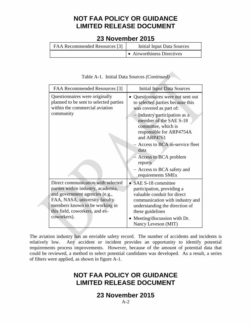
NOT FAA POLICY OR GUIDANCE LIMITED RELEASE DOCUMENT
23 November 2015
NOT FAA POLICY OR GUIDANCE LIMITED RELEASE DOCUMENT
23 November 2015 A-2
FAA Recommended Resources [3] Initial Input Data Sources • Airworthiness Directives
Table A-1. Initial Data Sources (Continued)
FAA Recommended Resources [3] Initial Input Data Sources Questionnaires were originally planned to be sent to selected parties within the commercial aviation community
• Questionnaires were not sent out to selected parties because this was covered as part of: − Industry participation as a
member of the SAE S-18 committee, which is responsible for ARP4754A and ARP4761
− Access to BCA in-service fleet data
− Access to BCA problem reports
− Access to BCA safety and requirements SMEs
Direct communication with selected parties within industry, academia, and government agencies (e.g., FAA, NASA, university faculty members known to be working in this field, coworkers, and ex-coworkers).
• SAE S-18 committee participation, providing a valuable conduit for direct communication with industry and understanding the direction of these guidelines
• Meeting/discussion with Dr. Nancy Leveson (MIT)
The aviation industry has an enviable safety record. The number of accidents and incidents is relatively low. Any accident or incident provides an opportunity to identify potential requirements process improvements. However, because of the amount of potential data that could be reviewed, a method to select potential candidates was developed. As a result, a series of filters were applied, as shown in figure A-1.
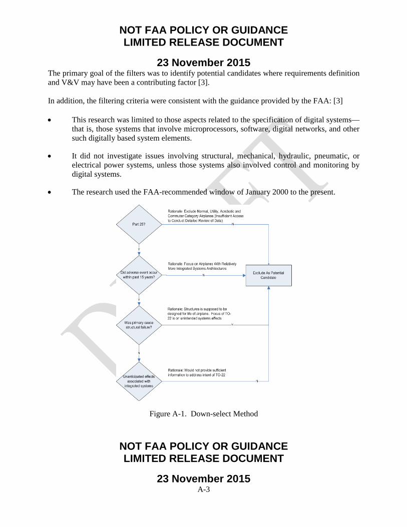
NOT FAA POLICY OR GUIDANCE LIMITED RELEASE DOCUMENT
23 November 2015
NOT FAA POLICY OR GUIDANCE LIMITED RELEASE DOCUMENT
23 November 2015 A-3
The primary goal of the filters was to identify potential candidates where requirements definition and V&V may have been a contributing factor [3]. In addition, the filtering criteria were consistent with the guidance provided by the FAA: [3] • This research was limited to those aspects related to the specification of digital systems—
that is, those systems that involve microprocessors, software, digital networks, and other such digitally based system elements.
• It did not investigate issues involving structural, mechanical, hydraulic, pneumatic, or electrical power systems, unless those systems also involved control and monitoring by digital systems.
• The research used the FAA-recommended window of January 2000 to the present.
Figure A-1. Down-select Method

NOT FAA POLICY OR GUIDANCE LIMITED RELEASE DOCUMENT
23 November 2015
NOT FAA POLICY OR GUIDANCE LIMITED RELEASE DOCUMENT
23 November 2015 A-4
The primary data sources reviewed were the National Transportation Safety Board (NTSB) database, the FAA lessons-learned data, and the BCA safety databases. The first filter excluded utility, acrobatic, and commuter category airplanes. This was primarily done because of the potential difficulty in getting additional data. The next filter considered the time frame. The research period was extended to Sept. 1998 to include the Swissair MD-11 event. [3] The next filter eliminated cases that appeared to be mostly structurally related. Fatigue is important, but translating these insights to digital avionics systems would be difficult. The next filter considered if the accident/incident was associated with unintended effects for highly integrated systems. As part of this review, candidates were removed that appeared to be operational in nature (e.g., an aircraft landing at the wrong airport). Pilot evaluation of aircraft level operations [3] was addressed through discussion with safety and requirements SMEs, who identified potential cases to review in further detail. Throughout this exercise, special attention was paid to how the information could be used from a requirements definition and V&V process. A.2 FINDINGS. Prior to any literature review or searching of internal and external databases, one candidate immediately stood out as a great candidate. However, the decision was made not to immediately select the case. Each step in this process allowed an evaluation for general trends in requirements definition and V&V. One of the key reasons that the potential candidates, listed in table A-2, were reviewed in further detail was to consider pilot evaluation of aircraft operation. It is for this reason that accidents such as the Swissair in-flight fire were included. It was not directly related to digital avionics systems, but it was an opportunity to consider this from an operational and wiring requirements perspective.
Table A-2. Potential Candidates
Date Airline Aircraft (A/C) Model Location 1998-09-02 Swissair Flight SR
111 MD-11 Nova Scotia
2000-01-31 Alaska Airlines Flight 261
MD-83 Pacific Ocean near Anacapa Island, CA
2007-08-20 China Airlines Flight 120
737-800 Okinawa, Japan

NOT FAA POLICY OR GUIDANCE LIMITED RELEASE DOCUMENT
23 November 2015
NOT FAA POLICY OR GUIDANCE LIMITED RELEASE DOCUMENT
23 November 2015 A-5
2009-06-01 Air France 447 A330-200 Atlantic Ocean 2010-11-04 Qantas 32 A380-800 Singapore 2005-08-01 Malaysian Airlines
777 777-200 Perth, Australia
After evaluating each of these events for potential research applicability, all but the 2005 Malaysian Airlines 777 incident were rejected for reasons listed in this appendix. [3] The 2005 Malaysian Airlines 777 incident occurred on 1 August 2005, at 17:03 Western Standard Time, as a Boeing 777-200 operated by Malaysian Airline System experienced a pitch up about 30 min after takeoff from Perth, Australia, while climbing through 36,000 ft with autopilot on [10]. During the pitch up, the aircraft climbed to 41,000 ft and the indicated airspeed dropped from 270 knots to 158 knots. The stick shaker and the stall warning indicator activated during the event. The flight landed uneventfully back at Perth [10]. On 29 August 2005, the FAA issued emergency Airworthiness Directive (AD) 2005-18-51 [9] to install Air Data Inertial Reference Unit-03 (ADIRU-03) software, stating that faulty ADIRU data could cause anomalies in 777 primary flight controls, autopilot, pilot displays, autobrakes, and autothrottles. A contributing safety factor was an anomaly that permitted inputs from a known faulty accelerometer to be processed by the ADIRU and used by other aircraft systems, including the primary flight computer and autopilot. [10] The potential research applicability included: • Requirements definition and V&V (particularly related to fault handling requirements)
• Cascading system failure effects and crew workload
• This case was selected because it would allow an in-depth review, particularly from a requirements definition and V&V perspective, of the integration between the different industry standards listed below:
− ARP4761, “Guidelines and Methods for Conducting the Safety Assessment Process on Civil Airborne Systems” [4]
NOT FAA POLICY OR GUIDANCE LIMITED RELEASE DOCUMENT
23 November 2015
NOT FAA POLICY OR GUIDANCE LIMITED RELEASE DOCUMENT
23 November 2015 A-6
− ARP4754A, “Guidelines for Development of Civil Aircraft and Systems” [1]
− Document-297 (DO-297), “Integrated Modular Avionics (IMA) Development Guidance and Certification Considerations” [7]
− DO-178B/C, “Software Considerations in Airborne Systems and Equipment Certification” [5]
− DO-254, “Design Assurance Guidance for Airborne Electronic Hardware” [6]
The research team also conducted a review of problem reports (from pre-flight systems architecture analyses and flight-test squawks) of recent product development programs. Specifically, requirements changes, systems architecture changes, and software changes were reviewed. To review possible linkages, the research team reviewed 46 ADs that addressed software involving Boeing aircraft. Three were selected for additional analysis, as shown in figure A-2.
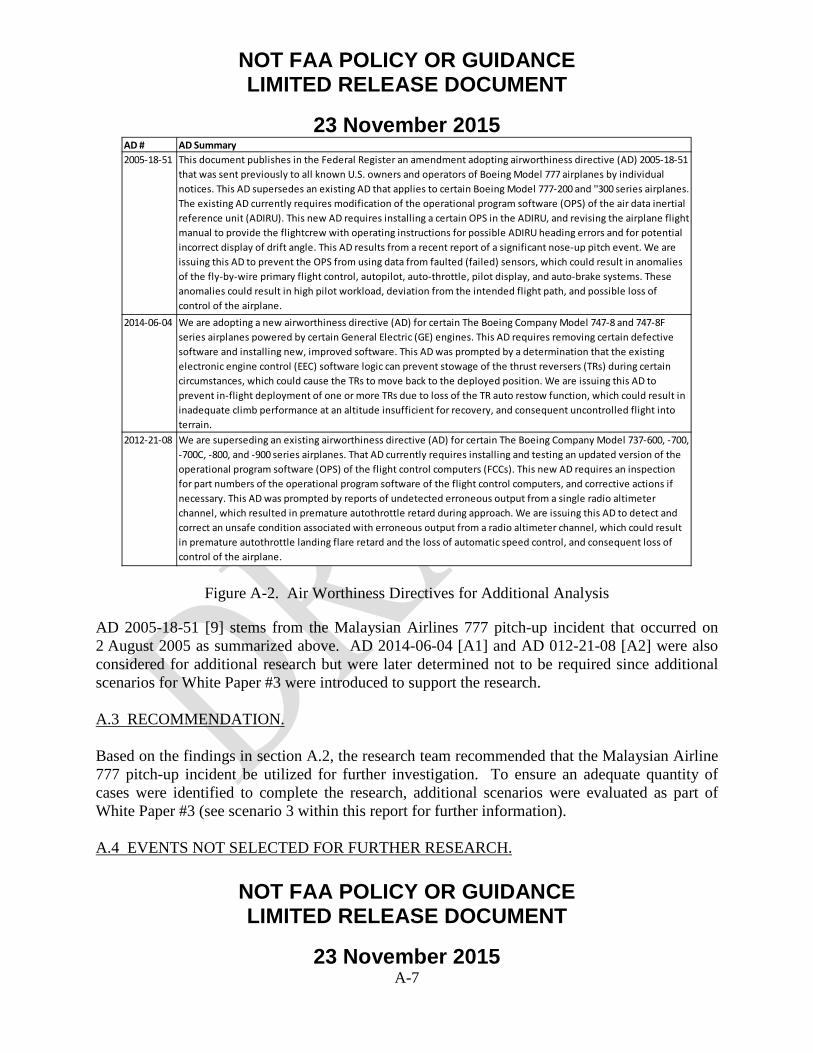
NOT FAA POLICY OR GUIDANCE LIMITED RELEASE DOCUMENT
23 November 2015
NOT FAA POLICY OR GUIDANCE LIMITED RELEASE DOCUMENT
23 November 2015 A-7
Figure A-2. Air Worthiness Directives for Additional Analysis
AD 2005-18-51 [9] stems from the Malaysian Airlines 777 pitch-up incident that occurred on 2 August 2005 as summarized above. AD 2014-06-04 [A1] and AD 012-21-08 [A2] were also considered for additional research but were later determined not to be required since additional scenarios for White Paper #3 were introduced to support the research. A.3 RECOMMENDATION. Based on the findings in section A.2, the research team recommended that the Malaysian Airline 777 pitch-up incident be utilized for further investigation. To ensure an adequate quantity of cases were identified to complete the research, additional scenarios were evaluated as part of White Paper #3 (see scenario 3 within this report for further information). A.4 EVENTS NOT SELECTED FOR FURTHER RESEARCH.
AD # AD Summary2005-18-51 This document publishes in the Federal Register an amendment adopting airworthiness directive (AD) 2005-18-51
that was sent previously to all known U.S. owners and operators of Boeing Model 777 airplanes by individual notices. This AD supersedes an existing AD that applies to certain Boeing Model 777-200 and ''300 series airplanes. The existing AD currently requires modification of the operational program software (OPS) of the air data inertial reference unit (ADIRU). This new AD requires installing a certain OPS in the ADIRU, and revising the airplane flight manual to provide the flightcrew with operating instructions for possible ADIRU heading errors and for potential incorrect display of drift angle. This AD results from a recent report of a significant nose-up pitch event. We are issuing this AD to prevent the OPS from using data from faulted (failed) sensors, which could result in anomalies of the fly-by-wire primary flight control, autopilot, auto-throttle, pilot display, and auto-brake systems. These anomalies could result in high pilot workload, deviation from the intended flight path, and possible loss of control of the airplane.
2014-06-04 We are adopting a new airworthiness directive (AD) for certain The Boeing Company Model 747-8 and 747-8F series airplanes powered by certain General Electric (GE) engines. This AD requires removing certain defective software and installing new, improved software. This AD was prompted by a determination that the existing electronic engine control (EEC) software logic can prevent stowage of the thrust reversers (TRs) during certain circumstances, which could cause the TRs to move back to the deployed position. We are issuing this AD to prevent in-flight deployment of one or more TRs due to loss of the TR auto restow function, which could result in inadequate climb performance at an altitude insufficient for recovery, and consequent uncontrolled flight into terrain.
2012-21-08 We are superseding an existing airworthiness directive (AD) for certain The Boeing Company Model 737-600, -700, -700C, -800, and -900 series airplanes. That AD currently requires installing and testing an updated version of the operational program software (OPS) of the flight control computers (FCCs). This new AD requires an inspection for part numbers of the operational program software of the flight control computers, and corrective actions if necessary. This AD was prompted by reports of undetected erroneous output from a single radio altimeter channel, which resulted in premature autothrottle retard during approach. We are issuing this AD to detect and correct an unsafe condition associated with erroneous output from a radio altimeter channel, which could result in premature autothrottle landing flare retard and the loss of automatic speed control, and consequent loss of control of the airplane.

NOT FAA POLICY OR GUIDANCE LIMITED RELEASE DOCUMENT
23 November 2015
NOT FAA POLICY OR GUIDANCE LIMITED RELEASE DOCUMENT
23 November 2015 A-8
The following events were reviewed in light of the litmus filter questions documented in figure A-1 and determined not to be included for further research for the reasons indicated. A.4.1 Swissair Flight SR 111. On 2 September 1998 Swissair Flight 111, a Boeing/McDonnell Douglas MD-11, departed John F. Kennedy International Airport, New York at 2018 eastern daylight savings time (0018 Universal Coordinated Time [UTC]), on a flight to Geneva, Switzerland. The flight included 215 passengers, and a crew of 2 pilots and 12 flight attendants. Approximately 1 hour into the flight, the pilots detected an unusual smell. Fourteen minutes later the pilots declared an emergency. Six minutes after the declared emergency, Flight 111 impacted the ocean about five nautical miles southwest of Peggy’s Cove, Nova Scotia, Canada. The aircraft was destroyed and there were no survivors [A3]. The key safety issues were: • Metalized Polyethylene Terephthalate thermal/acoustic insulation, in certain installations,
had significantly different flammability characteristics than had been demonstrated in compliance tests.
• The inability of the flight crew to easily remove electrical power from the In-Flight Entertainment Network system (lack of a flight deck switch) [A3].
The potential research applicability included: • Requirements definition, V&V processes.
• Unintended cascading effects of “non-essential” system on continued safe flight and landing.
This case was not selected because it would be difficult to extend the requirements V&V lessons learned to digital avionics systems. In addition, Advisory Circular 25.1701-1 “Certification of Electrical Wiring Interconnection Systems on Transport Category Airplanes” was released on 4 December 2007 and provides guidance for certification of Electrical Wiring Interconnection Systems [A4].

NOT FAA POLICY OR GUIDANCE LIMITED RELEASE DOCUMENT
23 November 2015
NOT FAA POLICY OR GUIDANCE LIMITED RELEASE DOCUMENT
23 November 2015 A-9
A.4.2 Alaska Airlines Flight 261. Alaska Airlines Flight 261 with 2 pilots, 3 cabin crew, and 83 passengers departed Puerto Vallarta (PVR), Mexico to Seattle, Washington with a scheduled stop in San Francisco, California [A3]. The airplane was functioning normally during the initial phase of flight but the horizontal stabilizer stopped responding to autopilot and pilot commands after the airplane passed through 23,400 ft. The pilots recognized the longitudinal trim system was not functioning but could not determine why. The safety board determined the probable cause of the accident was a loss of airplane pitch control resulting from in-flight failure of the horizontal stabilizer trim system jackscrew assembly’s Acme nut threads. The thread failure was caused by excessive wear resulting from Alaska Airlines’ insufficient lubrication of the jackscrew assembly. The key safety issues were: • Inadequate lubrication resulted in failure of the horizontal stabilizer jackscrew assembly
Acme nut threads.
• Undetected, plugged grease fitting passage [A3].
The potential research applicability included: • Requirements definition and V&V. • Flight crew situational awareness. This case, which was structural in nature, was not selected because it would be difficult to extend the requirements V&V lessons learned to digital avionics systems. A.4.3 China Airlines Flight 120. On 20 August 2007, a Boeing 737-800 operated by China Airlines departed from Taiwan, Taoyuan International Airport on a regularly scheduled flight to Naha Airport, Okinawa, Japan. Following landing and leading edge slat retraction, a failed portion of the slat track assembly was pressed through the slat track housing and penetrated the right main fuel tank, causing a fuel leak. At about 10:33 local time, fuel that had been leaking from the right wing tank during taxi and parking was ignited by hot engine surfaces and/or hot brakes, resulting in the aircraft being engulfed in flames [A3].

NOT FAA POLICY OR GUIDANCE LIMITED RELEASE DOCUMENT
23 November 2015
NOT FAA POLICY OR GUIDANCE LIMITED RELEASE DOCUMENT
23 November 2015 A-10
There were 165 passengers and crew onboard, consisting of 8 crewmembers and 157 passengers (including 2 infants). Everyone onboard was evacuated from the aircraft with no casualties. The aircraft was destroyed by the fire, leaving only part of the airframe intact. The key safety issue was: • A fuel tank breach, caused by a failed downstop assembly being pushed through the No.
5 slat can, which led to a fuel leak and subsequent fire that destroyed the airplane [A3].
The potential research applicability included: • Requirements definition and V&V (maintenance/service letters and bulletins). This case was not selected because it would be difficult to extend the requirements V&V lessons learned to digital avionics systems. A.4.4 Air France 447. On 31 May 2009, flight AF447 took off from Rio de Janeiro Galeão airport bound for Paris Charles de Gaulle airport. The airplane was in contact with the Brazilian air traffic control (ATC) at FL350. At around 2 hr 02 min, the Captain left the cockpit. At around 2 hr 08 min, the crew made a course change of about 10 degrees to the left, probably to avoid echoes detected by the weather radar [A3]. At 2 hr 10 min 05 sec, likely following the obstruction of the pitot probes in an ice crystal environment, the speed indications became erroneous and the automatic systems disconnected. The airplane’s flight path was not brought under control by the two copilots, who were rejoined shortly after by the Captain. The airplane went into a stall that lasted until the impact with the sea at 2 hr 14 min 28 sec. The key safety issues were: • Temporary inconsistency between the measured speeds, likely a result of the obstruction
of the pitot tubes by ice crystals, causing autopilot disconnection and reconfiguration to alternate law.
• Inappropriate crew control inputs destabilized the flight path.

NOT FAA POLICY OR GUIDANCE LIMITED RELEASE DOCUMENT
23 November 2015
NOT FAA POLICY OR GUIDANCE LIMITED RELEASE DOCUMENT
23 November 2015 A-11
• Failure to follow appropriate procedures for loss of displayed airspeed information.
• Failure to recognize that the aircraft had stalled—the crew failed to recognize that the aircraft had stalled and consequently did not make inputs that would have made it possible to recover from the stall [A3].
The potential research applicability included: • Crew situational awareness in presence of systems failures/degradations. This case was not selected because it would be difficult to extend the requirements V&V lessons learned to digital avionics systems. The obstruction of the pitot tubes had cascading failure effects. However, there was also operational error (inappropriate crew control inputs, failure to follow procedures, etc.). A.4.5 Qantas 32. On 4 November 2010, at 0157 UTC, an Airbus A380 aircraft, registered VH-OQA (OQA), being operated as Qantas flight 32, departed from runway 20 center (20C) at Changi Airport, Singapore for Sydney, New South Wales. Onboard the aircraft were 5 flight crew, 24 cabin crew, and 440 passengers (a total of 469 persons onboard) [A3]. Following a normal takeoff, the crew retracted the landing gear and flaps. The crew reported that, while maintaining 250 knots in the climb and passing 7,000 ft above mean sea level, they heard two almost coincident abrupt loud noises followed shortly after by indications of a failure of the No. 2 engine. A subsequent examination of the aircraft indicated that the No. 2 engine had sustained an uncontained failure of the Intermediate Pressure turbine disc. Sections of the liberated disc penetrated the left wing and the left wing-to-fuselage fairing, resulting in structural and systems damage to the aircraft. The key safety issues were: • The investigation team has inspected the damaged engine and components and
determined the sequence of events that led to the failure of the engine disc.
• The investigation is also examining the airframe and systems damage that resulted from the engine disc burst to understand its effect on those systems and the impact on flight

NOT FAA POLICY OR GUIDANCE LIMITED RELEASE DOCUMENT
23 November 2015
NOT FAA POLICY OR GUIDANCE LIMITED RELEASE DOCUMENT
23 November 2015 A-12
safety. That includes their effect on the aircraft’s handling and performance and on crew workload [A3].
A flight simulator program was used to conduct a number of tests in a certified A380 flight simulator. Analysis of the flight simulation test data is ongoing. The potential research applicability included: • Cascading system failure effects and crew workload. The A380 has an IMA architecture. Even though the initial failure source was an engine, there were cascading failure effects for multiple systems. This case was not selected due to the potential difficulties in obtaining the necessary data required to conduct an extensive analysis. A.4.6 ZA002 Dreamliner. 787-8 flight test airplane ZA002 experienced an onboard electrical fire during approach to Laredo, Texas on 9 November 2010. ZA002 lost primary electrical power as a result of an onboard electrical fire; backup systems, including the deployment of the Ram Air Turbine, functioned as expected and allowed the crew to complete a safe landing. The team determined that a failure in the P100 panel led to a fire involving an insulation blanket, which self-extinguished once the fault in the panel cleared. In response to the Laredo incident, Boeing developed minor design changes to power distribution panels on the 787 and updates to the systems software that manages and protects power distribution on the airplane. Engineers have determined that the fault began as either a short circuit or an electrical arc in the P100 power distribution panel, most likely caused by the presence of foreign debris. The design changes improved the protection within the panel. Software changes were also implemented to further improve fault protection. The contractor performed extensive analyses in support of the return to 787 flight-test activities. This case was not selected because, while there was a certain level of visibility with this event, it would not provide significant insights to requirements definition and V&V.
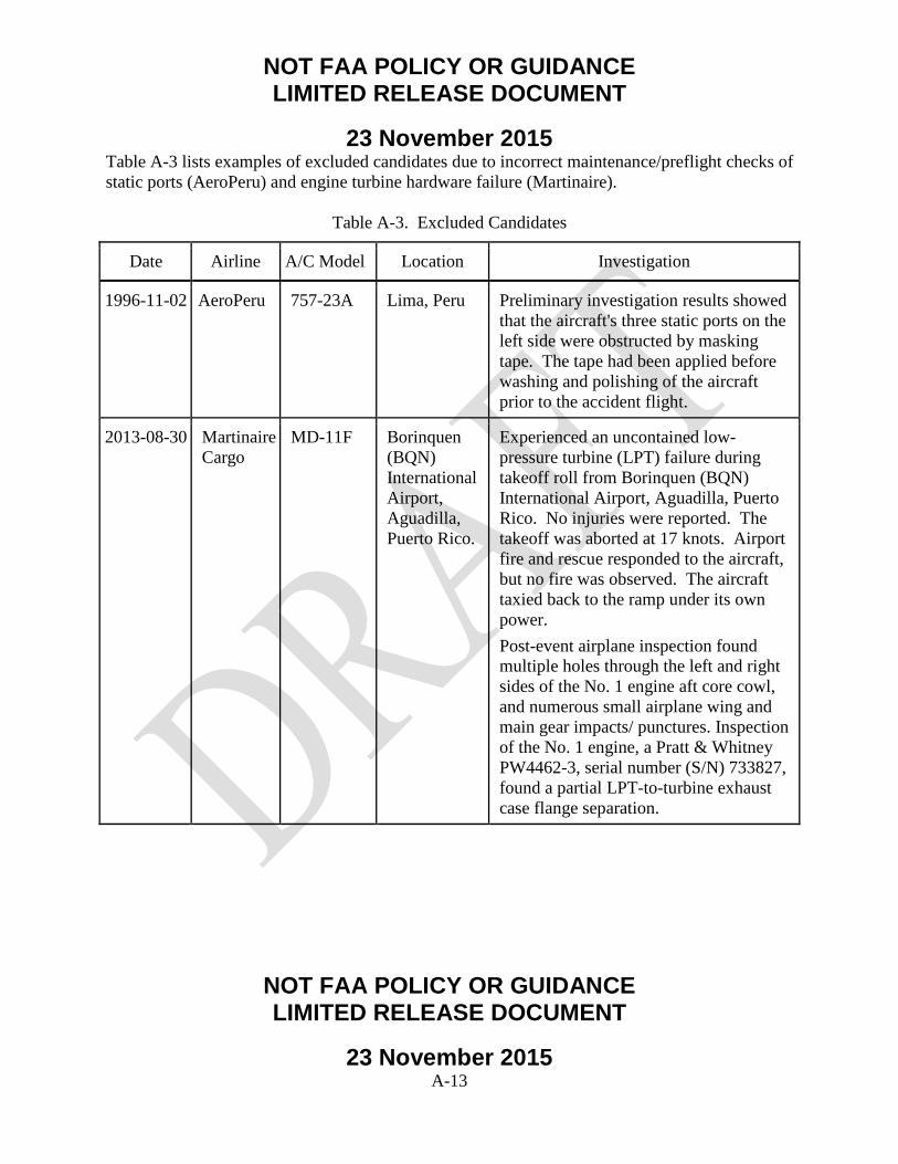
NOT FAA POLICY OR GUIDANCE LIMITED RELEASE DOCUMENT
23 November 2015
NOT FAA POLICY OR GUIDANCE LIMITED RELEASE DOCUMENT
23 November 2015 A-13
Table A-3 lists examples of excluded candidates due to incorrect maintenance/preflight checks of static ports (AeroPeru) and engine turbine hardware failure (Martinaire).
Table A-3. Excluded Candidates
Date Airline A/C Model Location Investigation
1996-11-02 AeroPeru 757-23A Lima, Peru Preliminary investigation results showed that the aircraft's three static ports on the left side were obstructed by masking tape. The tape had been applied before washing and polishing of the aircraft prior to the accident flight.
2013-08-30 Martinaire Cargo
MD-11F Borinquen (BQN) International Airport, Aguadilla, Puerto Rico.
Experienced an uncontained low-pressure turbine (LPT) failure during takeoff roll from Borinquen (BQN) International Airport, Aguadilla, Puerto Rico. No injuries were reported. The takeoff was aborted at 17 knots. Airport fire and rescue responded to the aircraft, but no fire was observed. The aircraft taxied back to the ramp under its own power. Post-event airplane inspection found multiple holes through the left and right sides of the No. 1 engine aft core cowl, and numerous small airplane wing and main gear impacts/ punctures. Inspection of the No. 1 engine, a Pratt & Whitney PW4462-3, serial number (S/N) 733827, found a partial LPT-to-turbine exhaust case flange separation.
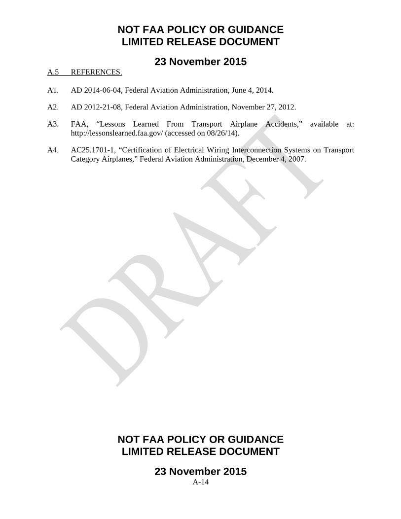
NOT FAA POLICY OR GUIDANCE LIMITED RELEASE DOCUMENT
23 November 2015
NOT FAA POLICY OR GUIDANCE LIMITED RELEASE DOCUMENT
23 November 2015 A-14
A.5 REFERENCES. A1. AD 2014-06-04, Federal Aviation Administration, June 4, 2014.
A2. AD 2012-21-08, Federal Aviation Administration, November 27, 2012.
A3. FAA, “Lessons Learned From Transport Airplane Accidents,” available at: http://lessonslearned.faa.gov/ (accessed on 08/26/14).
A4. AC25.1701-1, “Certification of Electrical Wiring Interconnection Systems on Transport Category Airplanes,” Federal Aviation Administration, December 4, 2007.

NOT FAA POLICY OR GUIDANCE LIMITED RELEASE DOCUMENT
23 November 2015
NOT FAA POLICY OR GUIDANCE LIMITED RELEASE DOCUMENT
23 November 2015 B-1
APPENDIX B—WHITE PAPER #2
White Paper #2 was the second of three white papers that identified and documented requirements definition, validation and verification (V&V) processes, and process interfaces [3]. The following subsections address the research approach, preliminary findings, and preliminary recommendations. B.1 RESEARCH APPROACH. The following research approach was used for White Paper #2: • Identified existing industry guidelines for requirements definition and V&V processes.
• Identified shortcomings in current processes in ARP4754A. [1]
• Identified additional processes that are currently not part of ARP4754 [2]/ARP4754A [1] or industry best practices. This included:
− Identified existing industry guidelines for interfaces between:
o Airplane.
o System/subsystem.
o Software.
o Airborne Electronic Hardware (AEH).
• Identified potential shortcomings in current process interfaces.
• Identified additional process interface clarifications (particularly transition to and from ARP4754A [1] and DO-178 [5]).
To identify potential shortcomings in industry guidelines, scenario(s) were considered in which following these industry guidelines perfectly could potentially fail to identify a potentially catastrophic condition. Both nominal and failure modes were considered in the evaluation of potential requirements process deficiencies. Understanding the intrasystem and intersystem behavior and validating an acceptable level of safety is maintained in the presence of cascading failure effects was an integral part of this evaluation.

NOT FAA POLICY OR GUIDANCE LIMITED RELEASE DOCUMENT
23 November 2015
NOT FAA POLICY OR GUIDANCE LIMITED RELEASE DOCUMENT
23 November 2015 B-2
B.2 PRELIMINARY FINDINGS. B.2.1 Overview of Existing Processes Related to Requirements Definition, Validation and Verification. Existing industry guidelines were reviewed to identify possible issues and shortcomings with the current process used by the commercial aviation industry regarding requirements definition and V&V for aircraft digital system requirements. Relevant industry processes related to requirements definition and V&V for avionics and electronic systems are listed in table B-1 below. Note: This table is provided to emphasize certain aspects of the listed documents and is not a comprehensive listing of all contents.
Table B-1. Existing Industry Processes
Industry Guideline
Purpose Primary Applicable Level
ARP4761, Guidelines and Methods for Conducting the Safety Assessment Process on Civil Airborne Systems and Equipment [4]
Provides guidelines and methods for performing the safety assessment for civil aircraft, including (but not limited to) safety analyses such as Functional Hazard Assessment (FHA), Preliminary System Safety Assessment (PSSA), and System Safety Assessment (SSA).
Airplane System/subsystem
ARP4754A, Guidelines for Development of Civil Aircraft and Systems [1]
Provides guidelines on the development assurance process. This includes validation of requirements and verification of the design implementation for certification and product assurance. The development planning elements consist of:
• Development • Safety Program • Requirements Management • Validation
Airplane System/subsystem

NOT FAA POLICY OR GUIDANCE LIMITED RELEASE DOCUMENT
23 November 2015
NOT FAA POLICY OR GUIDANCE LIMITED RELEASE DOCUMENT
23 November 2015 B-3
Industry Guideline
Purpose Primary Applicable Level
• Implementation Verification • Configuration Management • Process Assurance • Certification • Software integration process • Software configuration management • Software quality assurance process • Certification liaison
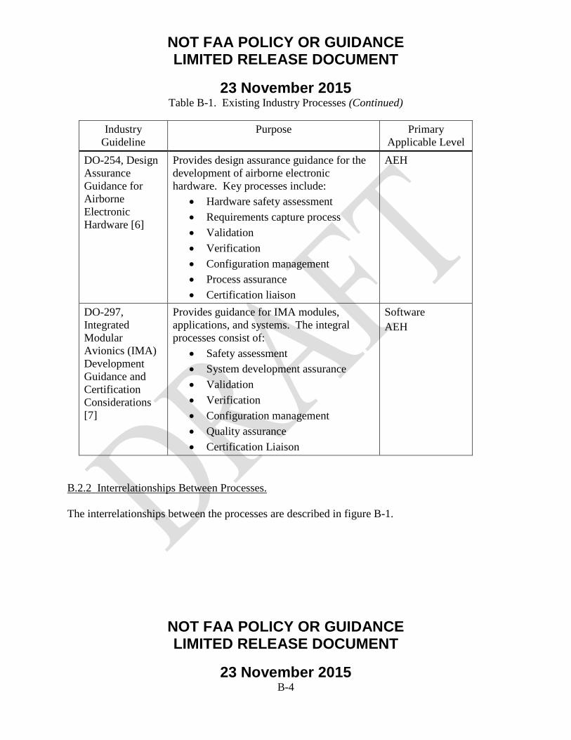
NOT FAA POLICY OR GUIDANCE LIMITED RELEASE DOCUMENT
23 November 2015
NOT FAA POLICY OR GUIDANCE LIMITED RELEASE DOCUMENT
23 November 2015 B-4
Table B-1. Existing Industry Processes (Continued)
Industry Guideline
Purpose Primary Applicable Level
DO-254, Design Assurance Guidance for Airborne Electronic Hardware [6]
Provides design assurance guidance for the development of airborne electronic hardware. Key processes include:
• Hardware safety assessment • Requirements capture process • Validation • Verification • Configuration management • Process assurance • Certification liaison
AEH
DO-297, Integrated Modular Avionics (IMA) Development Guidance and Certification Considerations [7]
Provides guidance for IMA modules, applications, and systems. The integral processes consist of:
• Safety assessment • System development assurance • Validation • Verification • Configuration management • Quality assurance • Certification Liaison
Software AEH
B.2.2 Interrelationships Between Processes. The interrelationships between the processes are described in figure B-1.

NOT FAA POLICY OR GUIDANCE LIMITED RELEASE DOCUMENT
23 November 2015
NOT FAA POLICY OR GUIDANCE LIMITED RELEASE DOCUMENT
23 November 2015 B-5
Figure B-1. Interrelationships Between Processes
Figure B-1 illustrates the flow between safety assessment processes covered by ARP4761 [4], development assurance processes covered by ARP4754 [2], and design assurance processes covered by DO-178 [5] and DO-254 [6]. For the purpose of this document, DO-178 and DO-254 will be referred to as “design assurance activities.” Function, failure, and safety information (particularly, derived safety requirements) flow from the ARP4761 processes to the ARP4754A processes. System design information flows from the ARP4754A processes to the ARP4761 processes. The transition from development assurance processes to software and hardware design assurance processes occurs when the requirements are allocated to hardware and software items. This is when the transition occurs from ARP4754/ARP4754A to DO-178 and DO-254. B.2.3 Information Flow From System Development Assurance Processes and Software and AEH Design Assurance Processes. Requirements are allocated to the following elements: • Hardware • Software
ARP4761
ARP4754
DO-297
DO-178 DO-254

NOT FAA POLICY OR GUIDANCE LIMITED RELEASE DOCUMENT
23 November 2015
NOT FAA POLICY OR GUIDANCE LIMITED RELEASE DOCUMENT
23 November 2015 B-6
• Development assurance level(s) and descriptions of Failure Condition(s), if applicable • Hardware allocated failure rates and exposure intervals • System description • Design constraints • System verification activities • Verification evidence ARP4754A [1] provides guidance in each of these areas. B.2.4 Information Flow From Hardware/Software Processes to System Development Assurance Processes. The hardware and software processes pass the following information to the system development assurance process: • Derived requirements • Hardware/software/system architecture description • Verification evidence • Failure rates and fault detection • Problem and change reports • Deficiencies or limitations of intended functionality • Installation drawings, schematics, part lists, etc. • System level verification plans
ARP4754A [1] provides guidance in each of these areas. B.2.5 Information Flow Between Hardware and Software Processes. The following information is passed between software and hardware processes: • Derived requirements • Hardware and software verification • Hardware and software incompatibilities ARP4754A [1] provides guidance in each of these areas.
B.2.6 Potential Errors in Information Flow. Any time that there is an interface and/or information flow, the possibility exists for an error or omission to be introduced. This can occur in the information flow between:
NOT FAA POLICY OR GUIDANCE LIMITED RELEASE DOCUMENT
23 November 2015
NOT FAA POLICY OR GUIDANCE LIMITED RELEASE DOCUMENT
23 November 2015 B-7
• Airplane to system • System to airplane • System to software • Software to system • System to hardware • Hardware to system • Software to hardware (by way of the system process) • Hardware to software (by way of the system process)
B.2.7 Clarifying Roles and Responsibilities for Different Information Flows. It is imperative to clearly understand the roles and responsibilities between the different information flows. There is sometimes, erroneously, an assumption that development assurance activities are the responsibility of the original equipment manufacturer (OEM) and that the supplier is responsible for software and hardware design assurance activities. The research team’s experience has noted that this incorrect assumption can sometimes occur (validated by discussions with Boeing supplier management and direct discussions with suppliers). The FAA has released the following Advisory Circulars (AC) that state how industry standards/guidelines are an acceptable means of compliance: • AC20-115C [B1], which recognizes DO-178C • AC20-152 [B2], which recognizes DO-254 • AC20-174 [B3], which recognizes ARP4754A
The industry guidelines, understandably, do not specify which roles are completed by the OEMs versus the suppliers. As shown in figure B-2, the transition from AC20-174 development assurance activities and AC20-115C software design assurance activities, or AC20-152 hardware design assurance activities, occurs with the requirements allocation to hardware and software. The red box indicates the focus area for the requirements allocation process. This step is key to ensuring that hardware and software design assurance activities start with a complete and correct set of requirements.

NOT FAA POLICY OR GUIDANCE LIMITED RELEASE DOCUMENT
23 November 2015
NOT FAA POLICY OR GUIDANCE LIMITED RELEASE DOCUMENT
23 November 2015 B-8
Figure B-2. Relationship of Advisory Circulars
The importance of clarifying the OEM and suppliers’ roles and responsibilities was highlighted in discussions with different programs and suppliers. This becomes particularly true for business scenarios, as shown in figure B-3, in which the requirements allocation to software and AEH is done by the supplier. (Note this is only one potential scenario. The following example is meant to highlight the importance of clearly understanding roles and responsibilities).

NOT FAA POLICY OR GUIDANCE LIMITED RELEASE DOCUMENT
23 November 2015
NOT FAA POLICY OR GUIDANCE LIMITED RELEASE DOCUMENT
23 November 2015 B-9
In this scenario, the OEM is following ARP4754A for development assurance and decomposes and derives airplane-level, system-level, and component-level requirements. A component-level specification is provided to the supplier before requirements allocation to hardware and software. The requirements allocation is typically done by the supplier. To illustrate the importance of supplier requirements allocation, figure B-3 indicates the notional delineation of responsibility between OEM and supplier.
Figure B-3. Typical OEM Versus Supplier Roles and Responsibilities
In figure B-3 above, this means that the supplier would have some development assurance activities. Figure B-4 shows this same concept from a slightly different perspective.

NOT FAA POLICY OR GUIDANCE LIMITED RELEASE DOCUMENT
23 November 2015
NOT FAA POLICY OR GUIDANCE LIMITED RELEASE DOCUMENT
23 November 2015 B-10
If the requirements can be directly allocated to hardware and/or software (i.e., no further requirements decomposition or derivation is required to do the allocation), then the supplier can transition to DO-178 software design assurance processes or DO-254 hardware design assurance processes. If the supplier is required to conduct requirements decomposition or derivation before the requirements can be allocated to hardware and/or software, then the supplier has development assurance activity. In particular, the supplier would need to validate that the decomposed requirements have been validated to be complete and correct.

NOT FAA POLICY OR GUIDANCE LIMITED RELEASE DOCUMENT
23 November 2015
NOT FAA POLICY OR GUIDANCE LIMITED RELEASE DOCUMENT
23 November 2015 B-11

NOT FAA POLICY OR GUIDANCE LIMITED RELEASE DOCUMENT
23 November 2015
NOT FAA POLICY OR GUIDANCE LIMITED RELEASE DOCUMENT
23 November 2015 B-12
Figure B-4. Requirements Decomposition/Derivation Required for Allocation
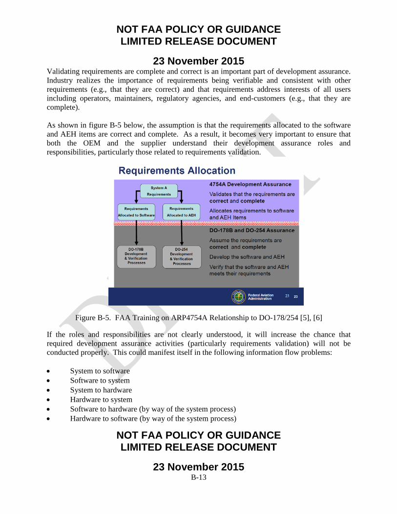
NOT FAA POLICY OR GUIDANCE LIMITED RELEASE DOCUMENT
23 November 2015
NOT FAA POLICY OR GUIDANCE LIMITED RELEASE DOCUMENT
23 November 2015 B-13
Validating requirements are complete and correct is an important part of development assurance. Industry realizes the importance of requirements being verifiable and consistent with other requirements (e.g., that they are correct) and that requirements address interests of all users including operators, maintainers, regulatory agencies, and end-customers (e.g., that they are complete). As shown in figure B-5 below, the assumption is that the requirements allocated to the software and AEH items are correct and complete. As a result, it becomes very important to ensure that both the OEM and the supplier understand their development assurance roles and responsibilities, particularly those related to requirements validation.
Figure B-5. FAA Training on ARP4754A Relationship to DO-178/254 [5], [6]
If the roles and responsibilities are not clearly understood, it will increase the chance that required development assurance activities (particularly requirements validation) will not be conducted properly. This could manifest itself in the following information flow problems: • System to software • Software to system • System to hardware • Hardware to system • Software to hardware (by way of the system process) • Hardware to software (by way of the system process)
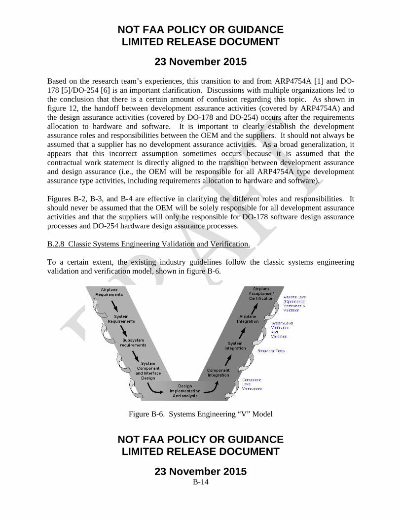
NOT FAA POLICY OR GUIDANCE LIMITED RELEASE DOCUMENT
23 November 2015
NOT FAA POLICY OR GUIDANCE LIMITED RELEASE DOCUMENT
23 November 2015 B-14
Based on the research team’s experiences, this transition to and from ARP4754A [1] and DO-178 [5]/DO-254 [6] is an important clarification. Discussions with multiple organizations led to the conclusion that there is a certain amount of confusion regarding this topic. As shown in figure 12, the handoff between development assurance activities (covered by ARP4754A) and the design assurance activities (covered by DO-178 and DO-254) occurs after the requirements allocation to hardware and software. It is important to clearly establish the development assurance roles and responsibilities between the OEM and the suppliers. It should not always be assumed that a supplier has no development assurance activities. As a broad generalization, it appears that this incorrect assumption sometimes occurs because it is assumed that the contractual work statement is directly aligned to the transition between development assurance and design assurance (i.e., the OEM will be responsible for all ARP4754A type development assurance type activities, including requirements allocation to hardware and software). Figures B-2, B-3, and B-4 are effective in clarifying the different roles and responsibilities. It should never be assumed that the OEM will be solely responsible for all development assurance activities and that the suppliers will only be responsible for DO-178 software design assurance processes and DO-254 hardware design assurance processes. B.2.8 Classic Systems Engineering Validation and Verification. To a certain extent, the existing industry guidelines follow the classic systems engineering validation and verification model, shown in figure B-6.
Figure B-6. Systems Engineering “V” Model

NOT FAA POLICY OR GUIDANCE LIMITED RELEASE DOCUMENT
23 November 2015
NOT FAA POLICY OR GUIDANCE LIMITED RELEASE DOCUMENT
23 November 2015 B-15
Starting with ARP4754A on the left side of the V, aircraft functions and requirements are developed and derived. There is the further decomposition or derivation of requirements at subsequently lower levels. From an ARP4754A perspective, a large part of the left side of the V is the validation of the requirements. The right side of the V involves the implementation verification of requirements at progressively higher levels. Similarly, ARP4761 follows a systems engineering V model as shown in figure B-7.
Figure B-7. Safety V Model
The left leg of the V represents a top-down requirement development and validation process. This includes the airplane FHA, the Preliminary Aircraft Safety Assessment, the System FHAs, the PSSA, and the preliminary (qualitative) Fault Tree Analyses (FTA). The inner V of figure B-7 represents the common-cause analyses steps used to validate that no common threats or failure modes violate the redundancy designed into the systems. The right leg represents a bottom-up verification process. It includes the Failure Modes and Effects Analyses, Quantitative FTAs, SSAs, and Airplane Safety Assessment. In and of itself, there is nothing incorrect with the V model (as modeled in either ARP4754A or ARP4761). However, it is not adequate, particularly when systems move from being federated to highly integrated. For highly integrated systems, it is important that the “missing middle” of the classic systems engineering V model be filled in as shown figure B-8.
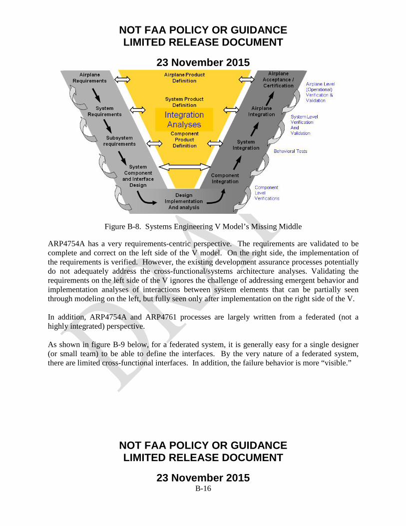
NOT FAA POLICY OR GUIDANCE LIMITED RELEASE DOCUMENT
23 November 2015
NOT FAA POLICY OR GUIDANCE LIMITED RELEASE DOCUMENT
23 November 2015 B-16
Figure B-8. Systems Engineering V Model’s Missing Middle
ARP4754A has a very requirements-centric perspective. The requirements are validated to be complete and correct on the left side of the V model. On the right side, the implementation of the requirements is verified. However, the existing development assurance processes potentially do not adequately address the cross-functional/systems architecture analyses. Validating the requirements on the left side of the V ignores the challenge of addressing emergent behavior and implementation analyses of interactions between system elements that can be partially seen through modeling on the left, but fully seen only after implementation on the right side of the V. In addition, ARP4754A and ARP4761 processes are largely written from a federated (not a highly integrated) perspective. As shown in figure B-9 below, for a federated system, it is generally easy for a single designer (or small team) to be able to define the interfaces. By the very nature of a federated system, there are limited cross-functional interfaces. In addition, the failure behavior is more “visible.”

NOT FAA POLICY OR GUIDANCE LIMITED RELEASE DOCUMENT
23 November 2015
NOT FAA POLICY OR GUIDANCE LIMITED RELEASE DOCUMENT
23 November 2015 B-17
Figure B-9. Federated Versus Integrated, Distributed Systems
For an integrated, distributed system, the interfaces need to be defined by many designers. By the very nature of an integrated, distributed system, there are increased cross-functional interfaces. Industry guidance is not as robust for the integration of distributed systems. The potential gaps in the existing processes include both nominal and failure modes. Table B-2 lists integral processes and industry guidance for their acceptability.
Table B-2. Industry Guidance Acceptability for Integral Processes
Integral Process Industry Guidance Acceptability for Highly Integrated, Distributed Systems
The processes currently used for initial definition of aircraft system-/function-level requirements.
Generally acceptable
The processes currently used for assigning aircraft system-/function-level requirements into implementation
Generally acceptable (particularly if OEM/supplier roles and responsibilities are clarified, as previously mentioned)

NOT FAA POLICY OR GUIDANCE LIMITED RELEASE DOCUMENT
23 November 2015
NOT FAA POLICY OR GUIDANCE LIMITED RELEASE DOCUMENT
23 November 2015 B-18
Integral Process Industry Guidance Acceptability for Highly Integrated, Distributed Systems
requirements, such as those needed for software and AEH. The processes currently used for validating single system-/function-level requirements, including pilot evaluation of aircraft-level operation.
Improvement needed to address critical gaps (ref. section B.2.9 below)
Table B-2. Industry Guidance Acceptability for Integral Processes (Continued)
Integral Process Industry Guidance Acceptability for Highly Integrated, Distributed Systems
The processes currently used for validating intersystem/cross-function requirements, including pilot evaluation of aircraft-level operation.
Improvement needed to address critical gaps (ref. section B.2.10 below)
The processes currently used for identifying missing requirements.
Improvement needed to address critical gaps (ref. section B.2.11 below)
The processes of using requirements-based testing for verification that the system/function operation is correct and complete.
Generally acceptable
B.2.9 Processes for Validating Single System-/Function-Level Requirements, Including Pilot Evaluation of Aircraft-Level Operation. In general, the processes for validating single system-/function-level requirements are acceptable (from an individual system perspective). However, improvement is needed for the pilot evaluation of the aircraft-level operation for single system-/function-level requirements. This is particularly true for resource systems where the systems architecture is now very interrelated and highly integrated. The possibility exists that certain failure modes, which in a federated system may have had a limited effect on other systems, may now have a cascading effect on other systems. The resulting cascading effects affect the ability of the flight crew to cope with the situation and provide for safe operation of the airplane.

NOT FAA POLICY OR GUIDANCE LIMITED RELEASE DOCUMENT
23 November 2015
NOT FAA POLICY OR GUIDANCE LIMITED RELEASE DOCUMENT
23 November 2015 B-19
The following generic example, as shown in figure B-10, illustrates this process gap. This potentially catastrophic situation would not be found if one simply followed the existing industry guidelines (particularly ARP4754A [1] and ARP4761 [4]).
Figure B-10. Unacceptable, Cumulative Cascading Failure Effects
The simplified diagram above shows the results of the cascading failure effects of electrical component failures. The purpose is to illustrate how the stack up of the cumulative system-level effects needs to be understood to ensure that an adequate level of safety is maintained in the presence of failures. At each point, all of the failures are acceptable from a systems perspective (acceptable loss of redundancy). However, the cumulative effect of acceptable systems-level effects is catastrophic at the airplane level. (Note: This is for illustrative purposes only; aircraft systems would not be designed and certified this way). B.2.10 Processes Currently Used for Validating Intersystem/Cross-Function Requirements, Including Pilot Evaluation of Aircraft-Level Operation. There is room for improvement in the industry process guidance for the validation of intersystem/cross-function requirements. This occurs at multiple levels: • Subsystem-to-subsystem • Component-to-component • Message-to-message

NOT FAA POLICY OR GUIDANCE LIMITED RELEASE DOCUMENT
23 November 2015
NOT FAA POLICY OR GUIDANCE LIMITED RELEASE DOCUMENT
23 November 2015 B-20
Figure B-11 shows the braking system for a more federated system. As expected, there are very few cross-functional interfaces. The basic elements include the spoiler handle, the brake system control unit, and the autobrake solenoid valve.
Figure B-11. More Federated System
Figure B-12 shows the same systems functionality, as implemented on a more integrated system. The same basic elements exist: spoiler handle, brake system control unit, and autobrake solenoid valve. However, there are significantly more cross-functional interfaces, for which better industry process guidance would be helpful.
Figure B-12. More Integrated System
Computer
Terminal
Terminal
Terminal Terminal

NOT FAA POLICY OR GUIDANCE LIMITED RELEASE DOCUMENT
23 November 2015
NOT FAA POLICY OR GUIDANCE LIMITED RELEASE DOCUMENT
23 November 2015 B-21
Another process gap is that there tends to be an assumption that if all of the airplane-level FHAs are acceptable, then the cumulative airplane-level effects of cascading effects will be acceptable. However, this is not a valid assumption for highly integrated systems. B.2.11 Process for Validating Missing Requirements. The process for validating missing requirements can be improved by: • Establishing an approach to validate and verify the intrasystem functionality to determine
that functions perform as required:
− System functions within its boundaries, using known definitions of its interfaces/boundaries.
− Describe system behavior to interfacing systems.
• Establishing an approach to verification of the intersystem functionality to determine proper content and performance:
− System functions properly in relation to associated functionality provided by interfacing and/or interacting systems.
− Validation of assumptions made at the intrasystem level.
− Validation and verification of end-to-end functionality and end-to-end signal timing.
• Identifying aircraft-level failure modes and effects considerations:
− Identify single and combination failure conditions to analyze, targeting key integration components/functions to determine that the impacts of failures are as expected and are acceptable.
− Include resource systems:
o Power sources, power distribution systems (engine, electric, hydraulic, pneumatic) and data networks.
o Systems and/or control signals that affect multiple aircraft functions.
B.2.12 Process Gaps vs. Implementation Escapes.

NOT FAA POLICY OR GUIDANCE LIMITED RELEASE DOCUMENT
23 November 2015
NOT FAA POLICY OR GUIDANCE LIMITED RELEASE DOCUMENT
23 November 2015 B-22
It is not possible to have consistent, perpetual flawless execution of any process. The objectives of development assurance processes are to minimize safety errors that could adversely affect safety. However, no development assurance process can guarantee that there will be no development assurance errors. Errors can occur for different reasons: • Process gaps do not indicate necessary work statement, increasing the chance for
developmental errors (which was the focus of this White Paper).
• Implementation escape in executing documented processes.
B.2.13 Summary of Preliminary Findings for White Paper #2. During the examination of requirements, V&V process, and interfaces among the processes, the team noted several potential gaps in industry guidance. A summary of our preliminary findings for White Paper #2 is listed below. • Review of industry guidelines showed the importance of clearly establishing the
development assurance roles and responsibilities between the OEM and the suppliers, particularly those related to requirements validation, to ensure a complete, correct set of requirements exists before beginning hardware and software design assurance activities.
• It is possible that existing development assurance processes may not adequately address the cross-functional/systems architecture analyses. Industry guidance potentially needs to be improved for the integration of distributed systems, to address potential gaps in validation processes, and to identify missing requirements for highly integrated, distributed systems.
• Processes to validate single system- and functional-level requirements are generally acceptable, but potential improvement is needed for pilot evaluation of the aircraft-level operation for single system-/functional-level requirements.
• Potential improvement is needed in the industry process guidance for the validation of intersystem/cross-functional requirements at the subsystem-to-subsystem level, the component-to-component level, and the message-to-message level.
B.2.14 Preliminary Recommendations.
NOT FAA POLICY OR GUIDANCE LIMITED RELEASE DOCUMENT
23 November 2015
NOT FAA POLICY OR GUIDANCE LIMITED RELEASE DOCUMENT
23 November 2015 B-23
The following preliminary recommendations are suggested for follow-on efforts in phases 2 and 3 of this task order: • Investigate processes to help identify missing requirements during the requirements
validation phase.
• Examine processes to ensure that OEMs and Suppliers are working to a complete and correct set of requirements to the greatest practical extent.
• Consider the potential need to clarify roles and responsibilities between OEMs and Suppliers potential regarding the transition from development assurance activities to design assurance activities (Note: It is recognized that this will vary based on the different business models).
• Identify potential gaps that may exist with processes to validate requirements for both single-system/function and intersystem/cross-function levels, including pilot evaluation of aircraft-level operation.
• Consider establishment of an approach to validate and verify intrasystem and intersystem functionality to determine that proper function, content, and performance exists. Include consideration of aircraft-level failure modes and effects.
B.3 REFERENCES. B1. FAA, “Lessons Learned From Transport Airplane Accidents,” available at:
http://lessonslearned.faa.gov (accessed on 08/26/14). B2. AC25.1701-1, “Certification of Electrical Wiring Interconnection Systems on Transport
Category Airplanes,” Federal Aviation Administration, December 4, 2007. B3. AC20-115C, “Airborne Software Assurance,” Federal Aviation Administration, July 19,
2013.

NOT FAA POLICY OR GUIDANCE LIMITED RELEASE DOCUMENT
23 November 2015
NOT FAA POLICY OR GUIDANCE LIMITED RELEASE DOCUMENT
23 November 2015 C-1
APPENDIX C—SUMMARY OF FINDINGS FROM PHASE 1 REPORT
C.1 SUMMARY OF PRELIMINARY FINDINGS. Anything that involves humans can result in human errors. Discussions with software (SW) and Airborne Electronic Hardware (AEH) subject matter experts (SME) validated that errors can occur in software and AEH that are not related to higher level requirements errors or omissions (i.e., the requirements had been properly allocated to hardware and software, but there were errors in the detailed implementation). These discussions highlighted the following: • Mistakes can happen anywhere in the development space.
• Design Assurance reviews can never be 100%.
• Design Assurance reviews still cannot guarantee a perfect product because the reviewer can make mistakes too. The purpose of having the robust processes in place is to minimize errors.
The research also revealed that there could be cases in which higher level requirements/constraints were not identified/communicated to the SW and AEH developers. From an industry guideline perspective, there is some room for improvement to mitigate this from occurring. The purpose of the ARP4754A [1] development assurance process is to address the increased integration of systems. Boeing has practical experience of validating and verifying complex and highly integrated systems. In addition, Boeing participated in the creation of Aerospace Information Report (AIR) 6110, Contiguous Aircraft/System Development Process Example [C1]. The purpose of this AIR was to provide a practical example of an implementation of ARP4754A (and its interrelationships with ARP4761 [4]). This AIR, while consistent with ARP4754A guidance, lacked key integration activities. (The systems integration guidance contained in section 4 of ARP4754A could be improved.) Additional research could examine the horizontal and vertical integration guidance provided in ARP4754A to assess whether additional guidance might be recommended. This research would also include potential process improvements in the direct links between ARP4754A and ARP4761, DO-178 [5], and DO-254 [6]. Stated differently, there is room for process improvement in industry guidelines related to horizontal and vertical integration:

NOT FAA POLICY OR GUIDANCE LIMITED RELEASE DOCUMENT
23 November 2015
NOT FAA POLICY OR GUIDANCE LIMITED RELEASE DOCUMENT
23 November 2015 C-2
• Airplane-level validation and verification (V&V) • Intersystem V&V • Intrasystem V&V • Component-level V&V From an industry guideline perspective, this could impact the robustness level of integrated V&V programs, including robustness of testing at component, subsystem, system, and system of systems levels. The systems architecture and integration activities are an integral contributor to development assurance. There are interfaces between the systems architecture and integration activities and the safety assessment activities. This interaction is important to identify design constraints for other interfacing systems (and their lower level hardware and software). As systems become more integrated, it is more likely that systems will be levying requirements and constraints on other systems (more so than in a federated systems architecture). Improving/clarifying the interactions between system development and the safety assessment process (particularly related to the integration of different systems) could be beneficial. This is not meant to imply that manufacturers and suppliers have not developed internal processes to analyze the systems architecture at its different levels. It just acknowledges that this information is not explicitly or clearly contained in the existing industry guidelines. If this is not done correctly, it increases the likelihood that DO-178 and DO-254 will not begin with a complete and correct set of requirements. As has been observed in numerous articles, the software is generally doing exactly what it was designed to do (which also supports the general adequacy of DO-178). When there are problems, they are usually caused by flawed (incomplete or incorrect) requirements. White Paper #2 contained additional information on methods to help validate missing requirements from an integration perspective. Another area of improvement in ARP4754A is providing additional guidance on the modification of existing systems. The majority of ARP4754A is written as if the system being developed is a “clean sheet” system. However, most systems are either modifying an existing system or using an existing system in a new environment. (Again, this is not meant to imply that manufacturers and suppliers have not developed their internal change impact assessment processes to support this type of activity; it is just an acknowledgement that there is a potential area for improvement in the industry guidelines).

NOT FAA POLICY OR GUIDANCE LIMITED RELEASE DOCUMENT
23 November 2015
NOT FAA POLICY OR GUIDANCE LIMITED RELEASE DOCUMENT
23 November 2015 C-3
The final recommended area for further investigation is identifying when the existing guidelines would not be adequate for the more integrated systems. For example, the research team identified cases in which: • All of the failures (first order and cascading effects) are acceptable from a systems
perspective (acceptable loss of redundancy, degraded performance, etc.). However, the cumulative effect of acceptable systems-level effects is catastrophic at the airplane level.
• All of the failures (first order and cascading effects) are acceptable for a given airplane level Functional Hazard Assessment (FHA). Cumulative effect of acceptable, individual airplane level FHA is catastrophic when viewed from a multi-airplane level FHA perspective.
Boeing recognized process gaps in the existing industry guidelines (particularly ARP4754A and ARP4761). It does not believe that it would have found systems architecture deficiencies for highly integrated systems if it had simply followed industry guidelines. C.2 PRELIMINARY RECOMMENDATIONS. The following preliminary recommendations are suggested for follow-on efforts in phases 2 and 3 of this task order: • Investigate the potential need to improve horizontal and vertical integration for V&V
processes at the component, intrasystem, intersystem, and airplane level.
• Investigate potential process improvements to facilitate requirements validation for the modification of existing systems.
• Consider potential process improvements to address cumulative effects of otherwise acceptable individual systems-level cascading effects.
C.3 SUMMARY OF WHITE PAPERS, PHASE 1 PRELIMINARY FINDINGS, AND
RECOMMENDATIONS FOR CONTINUATION OF PHASES 2 AND 3. White Paper #1 researched various information sources to identify adverse events in which the requirements definition and V&V may have been a contributing factor. A number of potential candidates were evaluated and rejected because they did not meet specific criteria. Following this process, the research team recommended that the 2005 Malaysian Airlines 777 incident be used for further research.

NOT FAA POLICY OR GUIDANCE LIMITED RELEASE DOCUMENT
23 November 2015
NOT FAA POLICY OR GUIDANCE LIMITED RELEASE DOCUMENT
23 November 2015 C-4
White Paper #2 examined requirements, V&V processes, and interfaces among the processes. The findings from the research showed there are potential improvements in industry guidance related to the roles and responsibilities of the Original Equipment Manufacturer (OEM) and supplier related to requirements validation. In addition, there are potential process improvements to address cross-functional/systems architecture analyses from a highly integrated, distributed systems’ perspective. Furthermore, there is a potential need to improve industry guidance for both single system-level requirements and functional-level requirements. White Paper #3 examined issues and shortcomings related to requirements definition, V&V processes, and interfaces, especially in scenarios where requirements were not properly validated or verified, or requirements did not exist at all. The findings showed there may be room for process improvement in industry validation and verification guidelines related to horizontal and vertical integration at the airplane, intersystem, intrasystem, and component levels. C.4 SUMMARY OF PHASE 1 PRELIMINARY FINDINGS. • The 2005 Malaysian Airlines 777 Incident has elements of cascading effects across
multiple integrated systems that make it an excellent event for further research (White Paper #1 finding).
• Review of industry guidelines showed the importance of clearly establishing the development assurance roles and responsibilities between the OEM and the suppliers, particularly those related to requirements validation, to ensure a complete, correct set of requirements exists before beginning hardware and software design assurance activities (White Paper #2 finding).
• It is possible that existing development assurance processes may not adequately address the cross-functional/systems architecture integration. Industry guidance potentially needs to be improved for the integration of distributed systems to address potential gaps in validation processes and to identify missing requirements for highly integrated, distributed systems (White Paper #2 finding).
• Processes to validate single system-level and functional-level requirements are generally acceptable, but potential improvement is needed for pilot evaluation of the aircraft-level operation for single system-level and functional-level requirements (White Paper #2 finding).
• Potential improvement is needed in the industry process guidance for the validation of intersystem/cross-functional requirements at the subsystem-to-subsystem level, the
NOT FAA POLICY OR GUIDANCE LIMITED RELEASE DOCUMENT
23 November 2015
NOT FAA POLICY OR GUIDANCE LIMITED RELEASE DOCUMENT
23 November 2015 C-5
component-to-component level, and the message-to-message level (White Paper #2 finding).
• The V&V processes at the component, intrasystem, intersystem, and airplane level may require improvements for horizontal and vertical integration (White Paper #3 finding).
• Existing processes to facilitate requirements validation for the modification of existing systems may have gaps (White Paper #3 finding).
• Existing processes may not address cumulative effects of otherwise acceptable individual systems-level cascading effects (White Paper #3 finding).
C.5 SUMMARY OF PRELIMINARY RECOMMENDATIONS. The research conducted in Phase 1 led to the following preliminary recommendations: 1. The research team recommended that the Malaysian Airline 777 pitch-up incident
(summarized in White Paper #1) be utilized for further review, along with the additional scenarios evaluated as part of White Paper #3.
2. Investigate processes to help identify missing requirements during the requirements validation phase (summarized in White Paper #2).
3. Examine processes to ensure that OEMs and Suppliers are working to a complete and correct set of requirements to the greatest practical extent (summarized in White Paper #2).
4. Consider the potential need to clarify roles and responsibilities between OEMs and Suppliers potential regarding the transition from development assurance activities to design assurance activities (Note: It is recognized that this clarification will vary based on the different business models) (summarized in White Paper #2).
5. Identify potential gaps that may exist with processes to validate requirements for both single-system/function and intersystem/cross-function levels, including pilot evaluation of aircraft-level operation (summarized in White Paper #2).
6. Consider establishment of an approach to validate and verify intrasystem functionality to determine that proper function, content, and performance exists. Include consideration of aircraft-level failure modes and effects (summarized in White Paper #2).

NOT FAA POLICY OR GUIDANCE LIMITED RELEASE DOCUMENT
23 November 2015
NOT FAA POLICY OR GUIDANCE LIMITED RELEASE DOCUMENT
23 November 2015 C-6
7. Investigate the potential need to improve horizontal and vertical integration for V&V processes at the component, intrasystem, intersystem, and airplane level (summarized in White Paper #3).
8. Investigate potential process improvements to facilitate requirements validation for the modification of existing systems (summarized in White Paper #3).
9. Consider potential process improvements to address cumulative effects of otherwise acceptable individual systems-level cascading effects (summarized in White Paper #3).
Each of these preliminary recommendations suggests that additional research be conducted in optional Phases 2 and 3 of this research. The approach to the research required by Phase 2 would involve a continuation of the systems engineering approach used in Phase 1 to classify and categorize the identified issues from Phase 1 and identify associated root causes of the requirements’ shortcomings. This work would involve an analysis of example scenarios (delineated in Phase 1- DS 6 - White Paper #3) to identify possible gaps and contributing factors and associated root cause(s). The approach to the research required by Phase 3 would likewise involve a continuation of the systems engineering approach utilized in Phase 1 to identify recommendations for possible solutions to the root cause(s) identified in Phase 2. This approach would involve an evaluation of current industry guidance and practices (outlined in Phase 1- DS 5 - White Paper #2) to formulate recommendations. The current state would be summarized, followed by a build-up and step-by-step description of implementing the possible solutions. C.6 REFERENCES. C1. SAE, SAI AIR6110, “Contiguous Aircraft/System Development Process Example,”
December 16, 2011.

NOT FAA POLICY OR GUIDANCE LIMITED RELEASE DOCUMENT
23 November 2015
NOT FAA POLICY OR GUIDANCE LIMITED RELEASE DOCUMENT
23 November 2015 D-1
APPENDIX D—SCENARIO MAPPING
Boeing’s initial approach for Phase 2 research involved examination of possible reasons that might cause or contribute to requirements errors, omissions, and conflicts in light of the eight scenarios outlined in Phase 1. During Phase 1, the Boeing team reviewed the nine possible reasons listed in the TO-22 performance work statement and found that they had potential applicability to the research. Additionally, Boeing identified two additional possible reasons involving horizontal and vertical integration for incomplete and incorrect requirements. The initial approach to Phase 2 research involved evaluating each scenario for applicability of the 11 possible reasons. This effort led to the creation of a mapping table to identify possible patterns of repetition. Figure D-1 maps possibilities that might cause or contribute to requirements errors, omissions, and conflicts to each scenario outlined in Phase 1.
NOT FAA POLICY OR GUIDANCE LIMITED RELEASE DOCUMENT
23 November 2015
NOT FAA POLICY OR GUIDANCE LIMITED RELEASE DOCUMENT
23 November 2015 D-2

NOT FAA POLICY OR GUIDANCE LIMITED RELEASE DOCUMENT
23 November 2015
NOT FAA POLICY OR GUIDANCE LIMITED RELEASE DOCUMENT
23 November 2015 D-3
Figure D-1. Scenario/Possibility Mapping Summary Table
Possibilities which might cause or contribute to requirements errors,
omissions and conflicts
1 2 3 4 5 6 7 8 9 10 11
System Complexity
Organizational Impediments
Sufficient Planning
Followed Publications
Schedules Experience Req'ts Validation
Req'ts Verification
System Integration
Horizontal Integration
Deficiencies
Vertical Integration
DeficienciesWP 3 Scenario # Description
1 Incorrect requirement discovered during V&V
Not a contributor
Not a contributor
Not a contributor
Not a contributor
Not a contributor
Not a contributor
Yes Not a contributor
Not a contributor
Not a contributor
Not a contributor
2 Incorrect translation/ implementation of a correct requirement
Not a contributor
Not a contributor
Not a contributor
Not a contributor
Not a contributor
Not a contributor
Not a contributor
Yes Yes Not a contributor
Not a contributor
3 Anomalous system operation requirement not specified
Yes Not a contributor
Not a contributor
Not a contributor
Not a contributor
Not a contributor
Yes Not a contributor
Yes Not a contributor
Not a contributor
4 Requirements not correctly specified for unexpected operation and/or failure conditions
Not a contributor
Not a contributor
Not a contributor
Not a contributor
Not a contributor
Not a contributor
Yes Yes Not a contributor
Yes Not a contributor
5 Stand-alone system requirements are incompatible with integrated systems operations
Not a contributor
Not a contributor
Not a contributor
Not a contributor
Not a contributor
Not a contributor
Yes Not a contributor
Yes Yes Yes
6 Inadequate or missing V&V of cascading failure conditions
Yes Not a contributor
Not a contributor
Not a contributor
Not a contributor
Not a contributor
Not a contributor
Not a contributor
Yes Yes Yes
7 Requirements do not anticipate (non-standard) expected crew actions
Yes Not a contributor
Not a contributor
Not a contributor
Not a contributor
Not a contributor
Yes Not a contributor
Not a contributor
Not a contributor
Not a contributor
8 Standalone system design change(s) not analyzed for effects on interfacing systems
Yes Not a contributor
Yes Not a contributor
Not a contributor
Not a contributor
Yes Yes Yes Yes Not a contributor