Embed Size (px)
Citation preview


DORF-RA-2016 HELPS
2
The Risk Assessment is prepared on the basis of information and details provided
by M/s. Dorf Ketal Speciality Catalysis (P) Ltd, Plot No. Z/108, Dahej, Dist. Bharuch
to HELPS during their course of the study. The assessment has been formulated by
team of qualified, experienced and competent persons.
The industrial emergency / disaster resulting from the accidental release of huge
quantity of volatile substances having toxic, flammable or explosive chemical
properties are not new to the chemical units. Therefore, the process of the chemical
industries have been continuously updating and developing its design and operating
techniques to overcome such problems. Further, a technique known as “Risk
Assessment” has been developed to assess the risk associated in the handling the
plants, storage areas and its consequences on human environment etc, if involves
either due to fire, explosion or toxic gas release.
For HELPS
Date : 25.08.2016
Vadodara
(J. J. VAGHELA) B.E.(Mech), LL.B., Sr. Factory Inspector (Retrd.), Industrial Safety & Health Professional, Expert & adviser
(MAYOOR J. VAGHELA) B.E., DIS, PGDIEM, MISNT, FIV Competent Person, Chartered Engineer, Industrial Safety Consultant, Valuer.

DORF-RA-2016 HELPS
3
INDEX
CHAPTER SUBJECT PAGE NO.
Preface --- 2
Index --- 3-4
DESCRIPTION SECTION:
1 Objective --- 6
2 Profile of Plant --- 10
3 Hazard Identification --- 14
4 Consequences Modelling --- 28
5 Risk Level --- 61
6 Suggestion and Recommendation --- 69-70
ANNEXURE SECTION:
Annexure 1 to 4 --- 71-79
DORF-RA-2016 HELPS
4
ANNEXURE INDEXANNEXURE INDEXANNEXURE INDEXANNEXURE INDEX
Annexure Annexure Annexure Annexure No.No.No.No.
SubjectSubjectSubjectSubject Page Page Page Page No.No.No.No.
1 Location Plan 72
2 Layout Plan 73
3 Storage of Hazardous Chemicals 74-75
4 Salient Properties Of Certain Hazardous Chemicals
76-79

DORF-RA-2016 HELPS
5

DORF-RA-2016 HELPS
6
1.11.11.11.1 INTRODUCTION INTRODUCTION INTRODUCTION INTRODUCTION
Chemical Process industr ies have undergone tremendous changes
dur ing the last f ive decades. Process Condit ions such as Pressure &
Temperature have become severe, concentrat ion of stored energy has
increased. P lants have grown in s ize and are often s ing le st ream. The
Scale of possible F i re, Explosion, Tox ic Release, Body Injur ies, and
Occupat ional Diseases has grown considerably. These Factors have
great ly increased the r isk for major industr ia l disasters, involv ing loss of
human l ives, plant & property and environmental degradat ion.
1.21.21.21.2 OBJECTIVES OBJECTIVES OBJECTIVES OBJECTIVES
The overal l object ives considered for R isk Assessment study are as
fol lows:
���� To ident ify var ious hazards in the storage and associated area of
the unit .
���� Assessing the var ious r isks involved
���� To consider the consequentia l impact on nearby areas,
populat ion, etc. in case of any accidental emergency s ituat ion
aris ing f rom the factory premises.
���� To evaluate and quanti fy the avai lable measures and resources
for contain ing any eventual i ty .
���� To study and suggest safety and control measure.

DORF-RA-2016 HELPS
7
1.31.31.31.3 METHODOLOGYMETHODOLOGYMETHODOLOGYMETHODOLOGY
The R isk Assessment as presented in the report is prepared based on
the Maximum Credible Accident Scenario (MCA) for cr it ical areas
where potent ia l of r isks are h igher. The var ious models are used to
quanti fy ing the loss of containment scenar io by est imat ing discharge
rate, the total quanti ty released, durat ion, extent of f lash and
evaporat ion etc. Methodology of QRA at a g lance given below ;
Sequence of R isk Assessment is g iven below
1. Gather required informat ion and documents
2. L ist out hazardous inventor ies and storage tank/ vessels detai ls
3. Def ine the fa i lure scenar ios and ident ify probable hazards
associated with them
4. Def ine parameters for each of the chemicals and each of hazards.
Identify
Hazards
/Risks
Analyse
Risks
Consequence
Analysis
Evaluate
and
Rank Risks
Control
Measures
(Manage
Risk)
Information
Collection
RISK
ASSESSMENT
PROCESS

DORF-RA-2016 HELPS
8
5. Def ine release type (cont inuous/ instantaneous) and determine
release rates.
6. Simulate selected cases for consequence of fa i lure scenar ios.
7. Summarize the consequences.
8. Superimpose vulnerable zones on the plot plan.
9. Appraise the extent of damage to plant and personnel .
10. Recommendat ion addit ional control measures/ remedial measured
required
1.41.41.41.4 Study are under this qraStudy are under this qraStudy are under this qraStudy are under this qra
This Quanti tat ive R isk Assessment is carr ied out for proposed storage
of C lass A chemicals which includes EO, Acetone, Toluene, Methanol
and Methy l Ethy l Ketone at the premise.
1.51.51.51.5 Software used Software used Software used Software used
Phast L ite software vers ion 7.1 from DNV GL is used for Consequence
Analys is during th is R isk Assessment.
Phast is the world's most comprehensive process industry hazard
analys is software tool for a l l stages of design and operat ion. Phast
examines the progress of a potent ia l incident f rom the in it ia l release to
far-f ie ld dispers ion including model l ing of pool spreading and
evaporat ion, and f lammable and tox ic effects.
Phast L ite is a user-f r iendly and powerful software tool with extensive
model l ing capabi l i t ies for hazard analys is , examining the progress of a
potent ia l incident f rom the ini t ia l re lease to far-f ie ld dispers ion. At its
core l ies the extensively val idated and ver i f ied UDM (Unif ied
Dispers ion Model) that enables r igorous model l ing of var ious release
types (jet , heavy and passive gas).

DORF-RA-2016 HELPS
9
1.61.61.61.6 ReferencesReferencesReferencesReferences
Some of the references which were used for QRA are i l lustrated as
under;
1. The Factor ies Act 1948 (1987) and Gujarat Factor ies Rules – 1963
(2004)
2. Manufacture, Storage & Import of Hazardous Chemicals Rules
1989 (2000)
3. Environmental (Protect ion) Act – 1986 (2004)
4. World Bank Technical papers “Techniques for assess ing Industr ia l
Hazards – A Manual” .
5. Methods for calculat ion of Physical effects (Yel low Book) by TNO
6. The Guidel ines for Chemical Process Quanti tat ive R isk Analys is,
Second Edit ion by CCPS
7. DNV Phast Software Manual

DORF-RA-2016 HELPS
10
2.12.12.12.1 INTRODUCTIONINTRODUCTIONINTRODUCTIONINTRODUCTION
Dorf Ketal, a special ty chemicals manufacturer and serv ices provider
with a global presence, offers i ts customers innovative chemical
solut ions and quick, decis ive response to solve the most dif f icult
problems. The company has two divis ions: Dorf Ketal Chemicals and
Dorf Ketal Specia l i ty Catalysts.
Dorf Ketal Chemicals is the leader in new chemistr ies for process
chemical solut ions in the crude oi l ref in ing and petrochemical
industr ies. Chemicals a lso serves the g lobal fuel addit ives market with
a broad portfol io of products and services and the grease and
lubr icant market with component addit ives.
Dorf Ketal Special i ty Catalysts is the market leader in organic t itanate
and zirconate technologies. I ts Tyzor® catalysts and crossl inkers
del iver value across a broad range of markets and appl icat ions.
Uni l ink™ and Clear l ink™ aromat ic and al iphat ic chain extenders serve
the g lobal polyurethane and Polyurea markets.
Dorf Ketal chemical experts, manufacturing plants and warehouses are
found in key industr ia l centers in the U.S. , India, China, Brazi l ,
Argent ina, Netherlands, U.A.E. , Bahrain, S ingapore and Malaysia. Our
global presence al lows us to serv ice cl ients in a l l major markets with
local expert ise and g lobal perspect ive.
Holding more than 300 patents, including 50 U.S. patents, Dorf Ketal
develops new chemistr ies that solve our customer’s most dif f icult
technical problems, add value and deliver rel iable results.

DORF-RA-2016 HELPS
11
2.22.22.22.2 Location of the unit Location of the unit Location of the unit Location of the unit
The Unit is located at Plot No.Z/108, Dahej, D ist. Bharuch.
The surroundings of the unit are descr ibed as below;
♦ North Side : Main Entry of the Unit and 30 Mtr
Wide Road
♦ South Side : 35 Mtr Power Corridor
♦ East Side : Plot No. Z/107
♦ West Side : Other unit
The locat ion plan is given at Annexure-1.
2.32.32.32.3 layoutlayoutlayoutlayout
The land occupied by Unit is i rregular shape, hav ing area of about
86565 Sq. mtr. The Unit wi l l have fol lowing Sheds/ Bui ldings / Sect ions
at its premises;
(1) Plant -1 Phase- 1
(2) Plant -2 Phase-2
(3) RMU
(4) Reveiv ing Water Tank
(5) WB Cabin
(6) Admin. Bui lding
(7) Amenties QC & OHC
(8) Ware House Phase 1 & 2
(9) CCOE Tankfarm (TF-3) Phase -1
(10) RM Tankfarm (TF-1) Phase -1
(11) Product Tankfarm (TF-2) Phase -1
(12) Product Tankfarm (TF-7) Phase -2
(13) EO Tankfarm (TF-4) Phase -2
(14) Intermediate Tankfam Phase -2
(15) Hydrogen Trol ley Parking Phase-1
(16) Uti l i ty , Substat ion & MCC Room Phase1 & 2

DORF-RA-2016 HELPS
12
(17) Breaker Room
(18) Transformer Yard
(19) Cool ing Tower Phase – 1 & 2
(20) Workshop
(21) Store
(22) Boi ler + TFH
(23) Coal Yard
(24) Scrap Yard
(25) Fi re Water Tank
(26) ETP
(27) Contractor Shed
(28) RM Tankfarm (TF-5) Phase-2
(29) Secur ity Cabin-1
(30) Secur ity Cabin-2, etc.
The Layout P lan of the Unit is g iven at Annexure- 2.
2.42.42.42.4 STORAGE STORAGE STORAGE STORAGE detailsdetailsdetailsdetails
The Company wi l l storage var ious chemicals as per their requirement,
proposed storage detai ls are given in Annexure -3.
2.52.52.52.5 Safety MeasuresSafety MeasuresSafety MeasuresSafety Measures will be will be will be will be PROVIDEDPROVIDEDPROVIDEDPROVIDED totototo EO EO EO EO TankTankTankTank
1. Safety Valves (2 Nos.)
2. Double Earth ing to tanks
3. Pressure Gauge
4. Temperature Gauge
5. EO stored under Nit rogen B lanket ing
6. Coi l for cool ing water circulat ion
7. Isolat ion Valves
8. Vent pipel ine with Scurbber
9. Explosion Resistance wall (RCC) toward plant s ide
10. L ightening Arrestor
11. Earth ing & bonding for pipel ine
12. Water Spr inkler on Tanks

DORF-RA-2016 HELPS
13
13. Provis ion of F i re Hydrant & Water Monitor
14. Fi re Ext inguishers
15. Dyke Wal l around the tank
16. Flame arrestor on valve vent ing
17. Isolated locat ion of Tank Farm with wire fencing.
18. Emergency instruct ion wi l l be displayed
19. Wind Indicator and s i ren wi l l be provided.
20. Smoking wi l l be str ict ly prohibited
21. Only author ised persons wi l l be al low to enter ins ide the area
2.62.62.62.6 Safety Measures will be PROVIDED to Safety Measures will be PROVIDED to Safety Measures will be PROVIDED to Safety Measures will be PROVIDED to
flammable chemicals storage tanksflammable chemicals storage tanksflammable chemicals storage tanksflammable chemicals storage tanks
1. Double Earth ing to tanks
2. Dyke Wal l around the tank
3. Isolat ion Valves
4. L ightening Arrestor
5. Earth ing & bonding for pipel ine
6. Provis ion of F i re Hydrant & Water Monitor
7. Fi re Ext inguishers
8. Flame arrestor
9. Isolated locat ion of Tank Farm with wire fencing.
10. Emergency instruct ion wi l l be displayed
11. Wind Indicator and s i ren wi l l be provided.
12. Smoking wi l l be str ict ly prohibited
13. Only author ised persons wi l l be al low to enter ins ide the area

DORF-RA-2016 HELPS
14
3.13.13.13.1 INTRODUCTIONINTRODUCTIONINTRODUCTIONINTRODUCTION
A hazard is an inherent physical or chemical character ist ic that has the
potent ia l for causing harm. A hazard Ident i f icat ion study is an
organized effort to ident ify and analyze the signif icance of hazardous
si tuat ions associated with a process or act iv i ty. Specif ical ly , Hazard
Ident if icat ion studies are used to pinpoint weaknesses in the design
and operat ion of faci l i t ies that could lead to accidental chemical
releases, f i res, or explosions. These studies provide organizat ions with
informat ion to help them to improve the safety and manage the r isk of
their operat ions.
Hazard Identi f icat ion studies usual ly focus on storages, process safety
issues, l ike the acute effects of unplanned chemical re leases on plant
personnel or the publ ic. These studies complement more tradit ional
industr ial health and safety act iv it ies, such as protect ion against s l ips
or fa l ls, use of personal protect ive equipment, monitor ing for
employee exposure to industr ia l chemicals, etc. Although Hazard
Ident if icat ion studies typical ly use qual itat ive methods to analyze
potent ia l equipment fa i lures and human errors that can lead to
accidents, the studies can also highl ight gaps in the management
systems of an organizat ion's process safety program.
3.23.23.23.2 TECHNIQUES OF HAZARD IDENTIFICATIONTECHNIQUES OF HAZARD IDENTIFICATIONTECHNIQUES OF HAZARD IDENTIFICATIONTECHNIQUES OF HAZARD IDENTIFICATION
Dif ferent techniques are adopted for Hazard Ident i f icat ion based on
hazardous substances, quant ity, type of process, gravi ty of hazards
etc.

DORF-RA-2016 HELPS
15
The var ious techniques can be i l lust rated as below;
1. Personal Vis its & Inspect ion of P lant by Team members
2. Safety Audits
3. On - S ite Emergency Plan
4. Check l ists
5. Feed back f rom plant personnel
6. Accident records
7. Safety Reports
8. Safety Manuals
9. Hazard & Operabil i ty Study (HAZOP)
10. Fault Tree Analys is (FTA)
11. Event Tree Analysis (ETA)
12. Prel iminary hazard Analys is (PHA)
13. Fai lure Modes and Ef fects Analys is (FMEA), etc.
3.33.33.33.3 Present Present Present Present RISK RISK RISK RISK Assessment of the Unit Assessment of the Unit Assessment of the Unit Assessment of the Unit
Dorf Ketal Specia l i ty Catalys is (P) Ltd is stor ing and handl ing EO,
Acetone, Toluene, Methanol and Methyl Ethyl Ketone, which is hav ing
Fi re, Explosion & Toxic hazard. Present R isk Assessment is carr ied out
for consider ing the storage & handling of EO, Acetone, Toluene,
Methanol and Methy l Ethy l Ketone.
3.43.43.43.4 Development of various scenariosDevelopment of various scenariosDevelopment of various scenariosDevelopment of various scenarios
The chart on next page is showing al l potentia l incident outcomes from
the release ( loss of containment) of a hazardous chemical. Further, the
propert ies of chemical, condit ions of release etc. a l l inf luence, which
of the logical paths shown in the chart. Though, i t is not detai led
enough to cover a l l possible permutat ions of phenomena that can
immediately result f rom a hazardous materia ls release.

DORF-RA-2016 HELPS
16
Chart showing development of various scenarios
Incident
Release
No Release No Impact
Tanker Explosion or
BLEVE or Fire
Gas Liquid and/or liquefied Gas
Liquid Flashers to vapour
Gas Vents
Pool Slowly Evaporates
Pool Fire Occurs
Vapour Cloud Travels Downwind
(if not ignited)
Vapour Plume Travels
Downwind Liquid
Rainout
Flame Jet Forms
(if ignited)
No Ignition – Toxic Vapour
Exposure
Plume Ignites, Explosion and/or Flash Fire Occurs
Pool Fire Occurs
No Ignition Toxic Vapour
Exposure
Vapour Cloud Ignites – Flash
Fire Occurs
Vapour Cloud Ignites –
Explosion

DORF-RA-2016 HELPS
17
3.53.53.53.5 Type of HType of HType of HType of Hazards azards azards azards
3.5.1 Pool Evaporation
The released f lammable materia l which is a l iquid stored below
its normal boi l ing point, wil l col lect in a pool. The geometry
of the pool wi l l be dictated by the surroundings. I f the
l iquid is stored under pressure above i ts normal boi l ing
point, then a f ract ion of the l iquid wi l l f lash into vapor
and the remaining port ion wi l l form a pool in the vicin i ty of
the release point. Once susta ined combustion is achieved,
l iquid f ires quick ly reach steady state burning. The heat
release rate is a function of the l iquid surface area exposed to
air. An unconf ined spi l l wi l l tend to have thin fuel depth
(typical ly less than 5 mm) which wi l l result in slower
burning rates. A conf ined spil l is l imited by the boundaries
(e.g. a dyked area) and the depth of the result ing pool is
greater than that for an unconf ined spi l l .
Vaporization scenarios
Vaporizat ion can occur when there is a leak in any of
the fol lowing S ituat ions:
• A l iquid at atmospheric temperature and pressure.
• A l iquid under pressure and above normal boi l ing point.
• The rates of vapourisat ion of the l iquid are different for
each of the two cases. In the case
• The l iquid after spi l lage is approximately at equi l ibr ium
and evaporates relat iv ity s lowly.
• In the case, the l iquid f lashes off when released, and the
l iquid remaining then undergoes s low evaporat ion.
Evaporat ion of a l iquid at atmospheric
temperature and pressure.
Evaporat ion f rom a pool of l iquid is essentia l ly a mass transfer
process that depends on the vapour pressure of the l iquid,
DORF-RA-2016 HELPS
18
wind velocity across the surface of the pool and ambient
weather condit ion.
A spi l lage of this k ind const i tutes a steady cont inuous
source of vapour. Unless the rate of evaporat ion due to
the combinat ion of vapour pressure and wind velocity is
high enough, i t is usual ly assumed that the heat t ransfer
from the a ir and the ground is suf f ic ient to provide the
latent heat of vapourisat ion.
Evaporat ion of a l iquid under pressure and above normal
boi l ing point When a pressur ized l iquid is re leased f rom
containment, a port ion f lashes off. This heat is obtained by
cooling the remain ing l iquid to i ts boi l ing point thus reaching
a state of equi l ibr ium f rom the high in equi l ibr ium
prevalent immediately on loss of containment. In practice, it
frequently happens that there is a s ignif icant amount of
spray format ion caused by the sudden release of
pressure and the v iolent boi l ing of l iquid. This spray
vaporizes rapidly by taking heat for vaporizat ion f rom air.
This spray l iquid format ion is assumed to equal to the gas
fract ion generated by f lash. The proport ion of l iquid ai rborne
is thus considerably high. Fol lowing f lashing, the res idual l iquid
is at i ts boil ing point. Vaporizat ion then cont inuous by
gain ing heat f rom surrounding as an essent ia l ly heat or
mass transfer l imited process.
This secondary stage of rate l imited vaporizat ion is usual ly
relat ively less important compared with the f lash off,
part icular ly with respect to format ion of f lammable gas clouds.

DORF-RA-2016 HELPS
19
3.5.2 Vapour Cloud dispersion
Following a cont inuous leak and formation of gas cloud, if
c loud does not ignite i t undergoes atmospheric dispersion in
accordance with the prevalent wind direction, speed, and
stabil i ty category. The object ive of carry ing out analys is of
cloud dispers ion is two fold. F i rst , i t provides the distance
(f rom the leak) at which the concentrat ion of f lammable
mater ia l fa l ls below the lower f lammabi l i ty l imit (LEL). Second
it provides the concentrat ion of the toxic substance to which
people may be exposed for short t ime, at vary ing distance
(f rom the leak).
3.5.3 JET FIRE
A Jet F ire, a lso referred to as a f lame jet, occurs when a
f lammable chemical is rapidly released from an opening in a
container and immediately catches on f i re—much l ike the f lame
from a blowtorch. A two-phase Jet F ire occurs when a gas that
has been l iquef ied under pressure is released. Because the
l iquid evaporates as it escapes, the chemical is released as an
aerosol spray—that is, a mixture of gas and t iny l iquid
droplets. Software assumes the Jet F ire release is or iented
vert ical ly , a lthough the wind can t i l t the f lames in the
downwind direct ion. Thermal radiat ion is the pr imary hazard
associated with a Jet F i re. Other potent ia l Jet F i re hazards
include smoke, tox ic by products f rom the f i re, and secondary
f i res and explosions in the surrounding area.
3.5.4 Pool fire
A pool f i re occurs when a f lammable l iquid forms a puddle on
the ground and catches on f ire. Thermal radiat ion is the
pr imary hazard associated with a pool f i re. Other potent ia l
pool f ire hazards include smoke, toxic by products f rom the
f i re, and secondary f i res and explosions in the surrounding
area. In some cases, heat f rom the pool f i re may weaken a

DORF-RA-2016 HELPS
20
leaking tank and cause i t to fa i l completely—in which case, a
BLEVE may occur. Typical ly , a BLEVE poses a greater threat than
a pool f ire. I f the chemical ins ide the tank is l ikely to BLEVE (for
example, i f the tank contains a l iquef ied gas).
3.5.5 BLEVEs
BLEVE stands for Boi l ing L iquid Expanding Vapour Explosion.
BLEVEs typical ly occur in closed storage tanks that contain a
l iquef ied gas, usual ly a gas that has been l iquef ied under
pressure. A gas can be l iquef ied by either cool ing
(refr igerat ing) it to a temperature below its boi l ing point or by
stor ing it at a h igh pressure. Both f lammable and non f lammable
l iquef ied gases may be involved in a BLEVE. Propane is an
example of a chemical that has been involved in many BLEVE
accidents. Most propane tanks at service stat ions contain
l iquid propane. These tanks are neither insulated nor
refr igerated, so the tank contents are at ambient temperature.
Since the ambient temperature is a lmost a lways signif icant ly
above propane's boi l ing point of -43.7 ºF, the tanks are h ighly
pressurized.
A common BLEVE scenar io happens when a container of
l iquef ied gas is heated by f i re, increasing the pressure with in
the container unt i l the tank ruptures and fai ls. When the
container fa i ls, the chemical is re leased in an explosion. I f the
chemical is above i ts boil ing point when the container fai ls ,
some or a l l of the l iquid wil l f lash-boi l—that is, instantaneously
become a gas. I f the chemical is f lammable, a burning gas
cloud cal led a f i rebal l may occur i f a s ignif icant amount of the
chemical f lash-boi ls. Software assumes that any l iquid not
consumed in the f i rebal l wi l l form a pool f i re. Software
est imates the thermal radiat ion hazard f rom a f i rebal l and/or a
pool f ire. Other potentia l BLEVE hazards include overpressure,
hazardous f ragments, smoke, and tox ic by products f rom the
DORF-RA-2016 HELPS
21
f i re. Software focuses on the thermal radiat ion because in
most BLEVEs thermal radiat ion impacts a greater area than the
overpressure and is the more s igni f icant threat.
3.5.6 Fireball
When you model a BLEVE, software assumes that a f i rebal l wi l l
form. The f i rebal l is made up of both the chemical that f lash-
boi ls when the tank fa i ls and the chemical that sprays out as an
aerosol dur ing the explosion. Software est imates that the
amount of chemical in the f i rebal l is three t imes the amount of
chemical that f lash boi ls. Any l iquid that does not part ic ipate
in the f i rebal l wi l l form a pool f i re. When you choose to
model a BLEVE s ituat ion, the program est imates the thermal
radiat ion f rom both f i res; it is not necessary to run an
addit ional Pool F i re scenar io. The pr imary hazard associated
with a f i rebal l is thermal radiat ion. However, i f there are other
chemicals near the f i rebal l , i t can t r igger addit ional f i res and
explosions. Explosion and hazardous f ragments. In a BLEVE, a
high-pressure explosion typical ly causes the container to
fragment. As the container breaks apart, i t may st r ike objects in
the surrounding area and create addit ional debris. The
container fragments and other debris—hazardous f ragments—
are swept up in the explosion and rapidly propel led by the
explosion over a wide area.. I f a BLEVE is l ikely to occur, f i rst
responders must take the necessary precaut ions to protect
themselves and others f rom the overpressure and hazardous
fragments.
3.5.7 Flash fires (flammable area)
When a f lammable vapour cloud encounters an ignit ion source,
the cloud can catch f i re and burn rapidly in what is cal led a
f lash f ire. Potent ial hazards associated with a f lash f i re include
thermal radiat ion, smoke, and tox ic by products f rom the f ire.
The f lammable area of the vapour cloud—that is, the area

DORF-RA-2016 HELPS
22
where a f lash f ire could occur at some t ime after the release.
The f lammable area is bounded by the Lower Explosive L imit
(LEL) and the Upper Explosive L imit (UEL). These l imits are
percentages that represent the concentrat ion of the fuel—that
is, the chemical—vapour in the air. I f the chemical vapour
comes into contact with an ignit ion source, it wi l l burn only if
i ts fuel-a ir concentrat ion is between the LEL and the UEL,
because that port ion of the cloud is al ready pre-mixed to the
r ight mixture of fuel and air for burning to occur. I f the fuel-a i r
concentrat ion is below the LEL, there is not enough fuel in the
air to susta in a f i re or an explosion—it is too lean. I f the fuel-
a ir concentrat ion is above the UEL, there is not enough oxygen
to susta in a f i re or an explosion because there is too much
fuel—it is too rich. (This is s imi lar to an engine that cannot start
because i t has been f looded with gasol ine.) I f a f lash f i re
occurs, the part of the cloud where the fuel-a i r concentrat ion
is above the UEL may cont inue to slowly burn as ai r mixes with
the cloud. You might expect that the LEL could be used as the
LOC to determine the areas in which a f i re might occur.
However, the concentrat ion levels est imated are t ime-
averaged concentrat ions. In an actual vapour cloud, there wi l l
be areas where the concentrat ion is h igher than the average
and areas where the concentrat ion is lower than the average.
This is cal led concentrat ion patchiness. Because of
concentrat ion patchiness, there wi l l be areas, cal led pockets,
where the chemical is in the f lammable range even though the
average concentrat ion has fa l len below the LEL. Some
experiments have shown that f lame pockets can occur in
places where the average concentrat ion is above 60% of the
LEL.

DORF-RA-2016 HELPS
23
3.5.8 Vapour cloud explosions
When a f lammable chemical is re leased into the atmosphere, it
forms a vapour cloud that wi l l disperse as i t t ravels downwind.
I f the cloud encounters an ignit ion source, the parts of the
cloud where the concentrat ion is with in the f lammable range
(between the LEL and UEL) wi l l burn. The speed at which the
f lame front moves through the cloud determines whether i t is a
def lagrat ion or a detonat ion. In some s ituat ions, the cloud wi l l
burn so fast that it creates an explosive force (blast wave). The
sever ity of a vapour cloud explosion depends on the
chemical, the cloud size at the t ime of ignit ion, the type of
ignit ion, and the congest ion level ins ide the cloud. The pr imary
hazards are overpressure and hazardous f ragments. Some
people may prefer to use the terms Lower F lammable L imit
(LFL) and Upper F lammable L imit (UFL), part icular ly i f they are
only concerned with f i res.
3.5.9 Overpressure
A major hazard associated with any explosion is overpressure.
Overpressure, a lso cal led a blast wave, refers to the sudden
onset of a pressure wave after an explosion. This pressure
wave is caused by the energy released in the in i t ia l
explosion—the bigger the ini t ia l explosion, the more damaging
the pressure wave. Pressure waves are near ly instantaneous,
travel l ing at the speed of sound. Although a pressure wave
may sound less dangerous than a f ire or hazardous f ragments,
it can be just as damaging and just as deadly. The pressure
wave radiates outward l ike a g iant burst of a ir , crashing into
anything in its path (generat ing hazardous fragments). I f the
pressure wave has enough power behind it , i t can l i f t people
off the ground and throw them up against nearby bui ldings or
trees. Addit ional ly , blast waves can damage bui ldings or even
knock them f lat—often injuring or k i l l ing the people ins ide
them. The sudden change in pressure can also affect pressure-

DORF-RA-2016 HELPS
24
sensit ive organs l ike the ears and lungs. The damaging effects
of the overpressure wi l l be greatest near the source of the
explosion and lessen as you move farther from the source.
3.63.63.63.6 Thermal Radiation Levels Thermal Radiation Levels Thermal Radiation Levels Thermal Radiation Levels
A Thermal Radiat ion Level is a threshold level of thermal radiat ion,
usual ly the level above which a hazard may ex ist.
The thermal radiat ion effects that people experience depend upon the
length of t ime they are exposed to a specif ic thermal radiat ion level.
Longer exposure durat ions, even at a lower thermal radiat ion level, can
produce serious physiological effects.
Thermal damage
The ef fect of thermal radiat ion on people is main ly a function
of intensity of radiat ion and exposure t ime. The ef fect is
expressed in terms of the probabi l i ty of death and different
degrees of burn. The fol lowing tables g ive the effect of var ious
levels of heat f lux.
DAMAGE DUE TO THERMAL RADIATION INTENSITY
Radiation intensity
(kW/m2) Observed effect
1.2 Solar heat at noon
1.6 Minimum level of pain threshold
2.0 PVC insulated cables damaged
4.0
Sufficient to cause pain to personnel if unable to
reach cover within 20 Seconds.
however blistering of the skin (second degree
burns) is likely; 0% lethality
6.4 Pain threshold reached after 8 Seconds
Second degree burns after 20 Seconds

DORF-RA-2016 HELPS
25
DAMAGE DUE TO THERMAL RADIATION INTENSITY
Continue..
Radiation intensity
(kW/m2) Observed effect
12.5
Minimum energy to ignite wood with a
flame; Melts plastic tubing.
1% lethality in one minute. First degree burns in
10 Seconds
16.0 Severe burns after 5 Seconds
25.0
Minimum energy to ignite wood at
identifying long exposure without a flame.
100% lethality in 1 minute.
Significant injury in 10 Seconds
37.5
Sufficient to cause damage to process
equipment, Severe damage to plant
100% lethality in 1 minute.
50% lethality in 20 Seconds
1% lethality in 10 Seconds.
3.73.73.73.7 OVERPRESSURE Levels OVERPRESSURE Levels OVERPRESSURE Levels OVERPRESSURE Levels
The most basic def ini t ion of an explosion is a sudden, intense release
of energy that often produces a loud noise, h igh temperatures, and
f ly ing debris, and generates a pressure wave. There are many types of
explosions and the causes and effects wi l l vary. Intent ional explosions
wi l l general ly—but not always—result in greater hazard damage.
Consider three pr imary hazards when deal ing with an explosion:
thermal radiat ion, overpressure, and hazardous f ragments (f ly ing
debris). Al l three of these hazards are not present in every explosion
and the sever ity of the hazard wi l l depend on the explosion. These
hazards typical ly last only for a br ief per iod direct ly fol lowing the
explosion. However, it is important to consider the potent ia l for
secondary explosions and f i res to occur before deciding that these
hazards no longer ex ist .

DORF-RA-2016 HELPS
26
Large objects ( l ike t rees and buildings) in the path of the pressure
wave can af fect its st rength and direct ion of travel. For example, i f
many bui ldings surround the explosion s ite, expect the actual
overpressure threat zone to be somewhat smal ler. But at the same
t ime, more hazardous f ragments could be generated as the blast
causes st ructural damage to those bui ldings. An Overpressure Level is
a threshold level of pressure f rom a blast wave, usual ly the pressure
above which a hazard may ex ist.
The overpressure values to the st ructural and physiological ef fects
produced and taken from Clancey, VJ, Diagnost ic Features of Explosion
Damage, 6th Internat ional Meet ing on Forensic Sciences, Edinburgh,
Scot land, 1972.
Explosion Overpressure Damage estimates
Pressure (psig)
Level of Damage
0.02 Annoying noise (137 dB), if of low frequency (10-15 Hz)
0.03 Occasional breaking of large glass windows already under strain
0.04 Loud noise (143 dB). Sonic boom glass failure
0.1 Breakage of small windows under strain
0.15 Typical pressure for glass breakage
0.3 “Safe distance” (probability 0.95 no serious damage beyond this value) Missile limit Some damage to house ceilings; 10% window glass broken
0.4 Limited minor structural damage
0.5 - 1.0 Large and small windows usually shattered
0.7 Minor damage to house structures
1.0 Partial demolition of houses, made uninhabitable
1 - 2 Corrugated asbestos shattered Corrugated steel or aluminium panels, fastenings fail, followed by buckling Wood panels (standard housing) fastenings fail, panels blown in
1.3 Steel frame of clad building slightly distorted
2 Partial collapse of walls and roofs of houses
2 - 3 Concrete or cinder block walls, not reinforced, shattered
2.3 Lower limit of serious structural damage
2.5 50% destruction of brickwork of houses

DORF-RA-2016 HELPS
27
Explosion Overpressure Damage estimates
Continue..
Pressure (psig)
Level of Damage
3 Heavy machines (3000 lb) in industrial building suffered little damage Steel frame building distorted and pulled away from foundations
3 - 4 Frameless, self-framing steel panel building demolished Rupture of oil storage tanks
4 Cladding of light industrial buildings ruptured
5 Wooden utility poles snapped Tall hydraulic press (40,000 lb) in building slightly damaged
5 - 7 Nearly complete destruction of houses
7 Loaded train wagons overturned
7 - 8 Brick panels 8-12" thick, not reinforced, fail by shearing/flexure
9 Loaded train boxcars completely demolished
10 Probable total destruction of buildings Heavy machines tools (7000 lb) moved and badly damaged Very heavy machine tools (12,000 lb) survived
300 Limit of crater lip

DORF-RA-2016 HELPS
28
4.14.14.14.1 CONSEQUENCE MODELLINGCONSEQUENCE MODELLINGCONSEQUENCE MODELLINGCONSEQUENCE MODELLING
Consequence analys is and calculat ions are performed by computer
software us ing various models val idated over a number of appl icat ions.
Consequence model l ing is carr ied out in Phast L i te.
4.24.24.24.2 WORST CASE & WORST CASE & WORST CASE & WORST CASE & MAXIMUM CREDIBLE MAXIMUM CREDIBLE MAXIMUM CREDIBLE MAXIMUM CREDIBLE SCENARIOSCENARIOSCENARIOSCENARIO
Fol lowing scenario are considered for th is QRA study ;
1. Catastrophic fa i lure of EO, Acetone, Methanol and MEK Tank
2. Leak from EO, Acetone, Methanol and MEK Tank
Radiat ion Heat, Over pressure Level and Gas concentrat ion due to
above scenarios are calculated and summary of the same is tabulated
in next page ;

29 HELPS
4.34.34.34.3 SummarySummarySummarySummary OF CONSEQUENCE ANALYSIS OF CONSEQUENCE ANALYSIS OF CONSEQUENCE ANALYSIS OF CONSEQUENCE ANALYSIS
a) Thermal Radiation Distance
Thermal Radiation effect Distance in meter at
Thermal Radiation Intensity Sr. No. For
Scenario plotting on map look at
Failure Case Consequence Chemical Weather Condition
4 (Kw/m2)
12.5 (Kw/m2)
37.5 (Kw/m2)
Category 1.5/F 210.32 130.54 74.54
Category 1.5/D 208.55 129.13 73.36 1 4.4.1 Catastrophic Rupture Late Pool Fire EO
Category 5/D 216.64 142.02 95.52
Category 1.5/F 72.67 59.39 48.94
Category 1.5/D 73.00 59.66 49.16 2 4.4.4 Leak from EO Tank Jet Fire EO
Category 5/D 64.83 51.06 42.05
Category 1.5/F 50.26 34.28 20.50
Category 1.5/D 50.37 34.42 20.66 3 4.4.5 Leak from EO Tank Early Pool Fire EO
Category 5/D 51.79 37.74 23.40
Category 1.5/F 133.31 85.38 49.99
Category 1.5/D 130.45 83.68 49.05 4 4.4.6 Leak from EO Tank Late Pool Fire EO
Category 5/D 123.88 83.87 56.97
30 HELPS
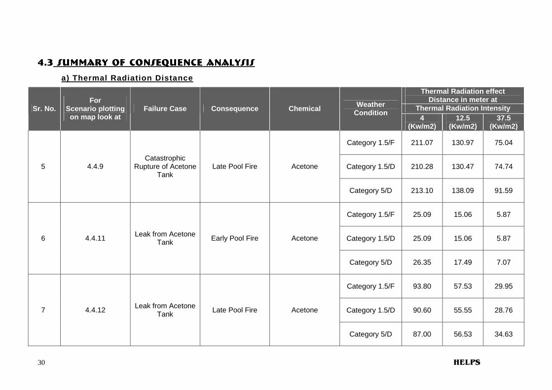
4.34.34.34.3 S S S Summary OF CONSEQUENCE ANALYSIS ummary OF CONSEQUENCE ANALYSIS ummary OF CONSEQUENCE ANALYSIS ummary OF CONSEQUENCE ANALYSIS
a) Thermal Radiation Distance
Thermal Radiation effect Distance in meter at
Thermal Radiation Intensity Sr. No. For
Scenario plotting on map look at
Failure Case Consequence Chemical Weather Condition
4 (Kw/m2)
12.5 (Kw/m2)
37.5 (Kw/m2)
Category 1.5/F 211.07 130.97 75.04
Category 1.5/D 210.28 130.47 74.74 5 4.4.9 Catastrophic
Rupture of Acetone Tank
Late Pool Fire Acetone
Category 5/D 213.10 138.09 91.59
Category 1.5/F 25.09 15.06 5.87
Category 1.5/D 25.09 15.06 5.87 6 4.4.11 Leak from Acetone Tank Early Pool Fire Acetone
Category 5/D 26.35 17.49 7.07
Category 1.5/F 93.80 57.53 29.95
Category 1.5/D 90.60 55.55 28.76 7 4.4.12 Leak from Acetone Tank Late Pool Fire Acetone
Category 5/D 87.00 56.53 34.63

31 HELPS
4.34.34.34.3 S S S Summary OF CONSEQUENCE ANALYSIS ummary OF CONSEQUENCE ANALYSIS ummary OF CONSEQUENCE ANALYSIS ummary OF CONSEQUENCE ANALYSIS a) Thermal Radiation Distance
Thermal Radiation effect Distance in meter at
Thermal Radiation Intensity Sr. No. For
Scenario plotting on map look at
Failure Case Consequence Chemical Weather Condition
4 (Kw/m2)
12.5 (Kw/m2)
37.5 (Kw/m2)
Category 1.5/F 101.51 45.04 -
Category 1.5/D 101.44 45.00 - 8 4.4.13 Catastrophic
Rupture of Toluene Tank
Late Pool Fire Toluene
Category 5/D 123.39 47.00 -
Category 1.5/F 24.27 13.89 4.84
Category 1.5/D 24.27 13.89 4.84 9 4.4.15 Leak from Toluene Tank Early Pool Fire Toluene
Category 5/D 26.07 17.27 5.88
Category 1.5/F 60.32 23.74 -
Category 1.5/D 59.63 23.37 - 10 4.4.16 Leak from Toluene Tank Late Pool Fire Toluene
Category 5/D 72.33 25.31 -
32 HELPS
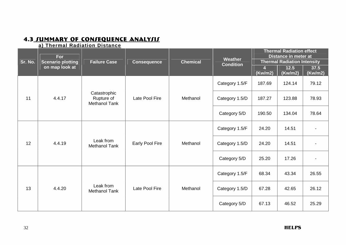
4.34.34.34.3 S S S Summary OF CONSEQUENCE ANALYSIS ummary OF CONSEQUENCE ANALYSIS ummary OF CONSEQUENCE ANALYSIS ummary OF CONSEQUENCE ANALYSIS a) Thermal Radiation Distance
Thermal Radiation effect Distance in meter at
Thermal Radiation Intensity Sr. No. For
Scenario plotting on map look at
Failure Case Consequence Chemical Weather Condition
4 (Kw/m2)
12.5 (Kw/m2)
37.5 (Kw/m2)
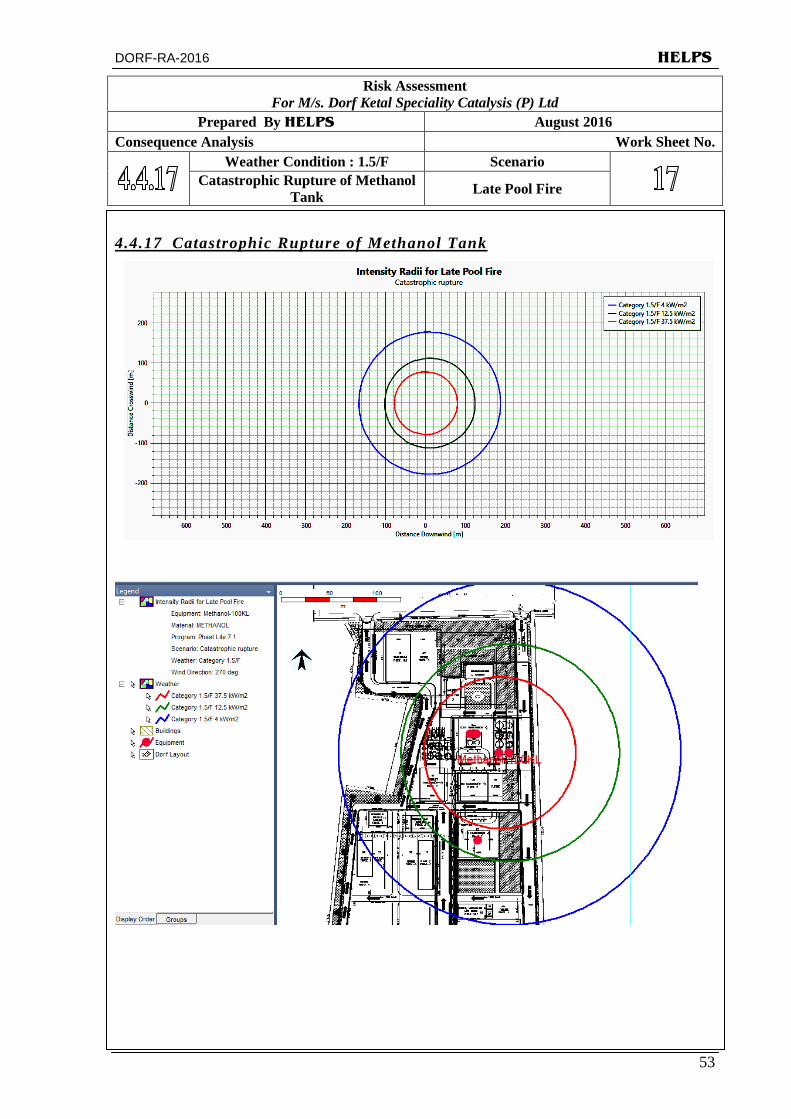
Category 1.5/F 187.69 124.14 79.12
Category 1.5/D 187.27 123.88 78.93 11 4.4.17 Catastrophic Rupture of
Methanol Tank Late Pool Fire Methanol
Category 5/D 190.50 134.04 78.64
Category 1.5/F 24.20 14.51 -
Category 1.5/D 24.20 14.51 - 12 4.4.19 Leak from Methanol Tank Early Pool Fire Methanol
Category 5/D 25.20 17.26 -
Category 1.5/F 68.34 43.34 26.55
Category 1.5/D 67.28 42.65 26.12 13 4.4.20 Leak from Methanol Tank Late Pool Fire Methanol
Category 5/D 67.13 46.52 25.29

33 HELPS
4.34.34.34.3 Summary OF CONSEQUENCE ANALYSIS (Continue…)Summary OF CONSEQUENCE ANALYSIS (Continue…)Summary OF CONSEQUENCE ANALYSIS (Continue…)Summary OF CONSEQUENCE ANALYSIS (Continue…)
a) Thermal Radiation Distance
Thermal Radiation effect Distance in meter at
Thermal Radiation Intensity Sr. No. For
Scenario plotting on map look at
Failure Case Consequence Chemical Weather Condition
4 (Kw/m2)
12.5 (Kw/m2)
37.5 (Kw/m2)
Category 1.5/F 187.69 124.14 79.12
Category 1.5/D 187.27 123.88 78.93 14 4.4.21 Catastrophic
Rupture of Methyl Ethyl Ketone Tank
Late Pool Fire Methyl Ethyl Ketone
Category 5/D 190.50 134.04 78.64
Category 1.5/F 24.20 14.51 -
Category 1.5/D 24.20 14.51 - 15 4.4.23 Leak from Methyl Ethyl Ketone Tank Early Pool Fire Methyl Ethyl
Ketone
Category 5/D 25.20 17.26 -
Category 1.5/F 68.34 43.34 26.55
Category 1.5/D 67.28 42.65 26.12 16 4.4.24 Leak from Methyl Ethyl Ketone Tank Late Pool Fire Methyl Ethyl
Ketone
Category 5/D 67.13 46.52 25.29

34 HELPS
4.4.4.4.4444 Summary OF CONSEQUENCE ANALYSIS Summary OF CONSEQUENCE ANALYSIS Summary OF CONSEQUENCE ANALYSIS Summary OF CONSEQUENCE ANALYSIS b) Overpressure Distance
Maximum Distance (m) at Overpressure Level Sr. No.
For Scenario plotting on map look at
Failure Case Consequence Chemical Weather Condition
0.02068 bar
0.1379 bar
0.2068 bar
Category 1.5/F 554.94 262.00 245.72
Category 1.5/D 556.87 250.70 236.97 17
4.4.2
Catastrophic Rupture of EO
Tank
Vapour Cloud Explosion – Late
Ignition EO
Category 5/D 543.84 190.22 177.75
Category 1.5/F 285.07 155.33 145.08
Category 1.5/D 236.39 150.136 143.32 18
4.4.8
Leak from 12.5 mm dia hole in EO
Tank
Vapour Cloud Explosion – Late
Ignition EO
Category 5/D 152.78 91.43 86.59

35 HELPS
4.44.44.44.4 Summary OF CONSEQUENCE ANALYSIS Summary OF CONSEQUENCE ANALYSIS Summary OF CONSEQUENCE ANALYSIS Summary OF CONSEQUENCE ANALYSIS (Continue…)(Continue…)(Continue…)(Continue…) b) Overpressure Distance
Maximum Distance (m) at Overpressure Level Sr. No.
For Scenario plotting on map look at
Failure Case Consequence Chemical Weather Condition
0.02068 bar
0.1379 bar
0.2068 bar
Category 1.5/F 292.47 159.75 150.76
Category 1.5/D 265.10 157.76 151.48 19 4.4.10 Catastrophic Rupture of
Acetone Tank
Vapour Cloud Explosion – Late
Ignition Acetone
Category 5/D 164.03 87.89 83.85
Category 1.5/F 116.19 59.73 55.27
Category 1.5/D 112.53 65.78 62.21 20 4.4.14 Catastrophic Rupture of
Toluene Tank
Vapour Cloud Explosion – Late
Ignition Toluene
Category 5/D 74.09 41.50 41.16
Category 1.5/F 375.29 151.98 86.18
Category 1.5/D 297.48 112.54 51.18 21 4.4.18 Catastrophic Rupture of
Methanol Tank
Vapour Cloud Explosion – Late
Ignition Methanol
Category 5/D 293.53 109.71 48.65
Category 1.5/F 508.97 191.74 102.97
Category 1.5/D 435.76 150.41 59.88 22 4.4.22 Catastrophic
Rupture of Methyl Ethyl Ketone Tank
Vapour Cloud Explosion – Late
Ignition
Methyl Ethyl Ketone
Category 5/D 432.20 148.06 57.65
36 HELPS
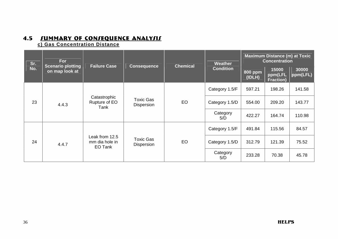
4.4.4.4.5555 Summary OF CONSEQUENCE ANALYSIS Summary OF CONSEQUENCE ANALYSIS Summary OF CONSEQUENCE ANALYSIS Summary OF CONSEQUENCE ANALYSIS c) Gas Concentration Distance
Maximum Distance (m) at Toxic Concentration Sr.
No.
For Scenario plotting on map look at
Failure Case Consequence Chemical Weather Condition
800 ppm (IDLH)
15000 ppm(LFL Fraction)
30000 ppm(LFL)
Category 1.5/F 597.21 198.26 141.58
Category 1.5/D 554.00 209.20 143.77 23
4.4.3
Catastrophic Rupture of EO
Tank
Toxic Gas Dispersion EO
Category 5/D 422.27 164.74 110.98
Category 1.5/F 491.84 115.56 84.57
Category 1.5/D 312.79 121.39 75.52 24
4.4.7
Leak from 12.5 mm dia hole in
EO Tank
Toxic Gas Dispersion EO
Category 5/D 233.28 70.38 45.78

DORF-RA-2016 HELPS
37
Risk Assessment For M/s. Dorf Ketal Speciality Catalysis (P) Ltd
Prepared By HELPS August 2016 Consequence Analysis Work Sheet No.
Weather Condition : 1.5/F Scenario Catastrophic Rupture of EO Tank Late Pool Fire
4.4.1 Catastrophic Rupture of EO Tank

DORF-RA-2016 HELPS
38
Risk Assessment For M/s. Dorf Ketal Speciality Catalysis (P) Ltd
Prepared By HELPS August 2016 Consequence Analysis Work Sheet No.
Weather Condition : 1.5/F Scenario Catastrophic Rupture of EO Tank Late Explosion
4.4.2 Catastrophic Rupture of EO Tank

DORF-RA-2016 HELPS
39
Risk Assessment For M/s. Dorf Ketal Speciality Catalysis (P) Ltd
Prepared By HELPS August 2016 Consequence Analysis Work Sheet No.
Weather Condition : 1.5/F Scenario Catastrophic Rupture of EO Tank Toxic Dispersion
4.4.3 Catastrophic Rupture of EO Tank

DORF-RA-2016 HELPS
40
Risk Assessment For M/s. Dorf Ketal Speciality Catalysis (P) Ltd
Prepared By HELPS August 2016 Consequence Analysis Work Sheet No.
Weather Condition : 1.5/F Scenario Leak from EO Tank Jet Fire
4.4.4 Leak from EO Tank

DORF-RA-2016 HELPS
41
Risk Assessment For M/s. Dorf Ketal Speciality Catalysis (P) Ltd
Prepared By HELPS August 2016 Consequence Analysis Work Sheet No.
Weather Condition : 1.5/F Scenario Leak from EO Tank Early Pool Fire
4.4.5 Leak from EO Tank

DORF-RA-2016 HELPS
42
Risk Assessment For M/s. Dorf Ketal Speciality Catalysis (P) Ltd
Prepared By HELPS August 2016 Consequence Analysis Work Sheet No.
Weather Condition : 1.5/F Scenario Leak from EO Tank Late Pool Fire
4.4.6 Leak from EO Tank
DORF-RA-2016 HELPS
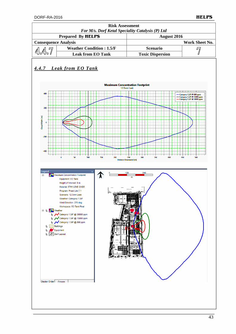
43
Risk Assessment For M/s. Dorf Ketal Speciality Catalysis (P) Ltd
Prepared By HELPS August 2016 Consequence Analysis Work Sheet No.
Weather Condition : 1.5/F Scenario Leak from EO Tank Toxic Dispersion
4.4.7 Leak from EO Tank

DORF-RA-2016 HELPS
44
Risk Assessment For M/s. Dorf Ketal Speciality Catalysis (P) Ltd
Prepared By HELPS August 2016 Consequence Analysis Work Sheet No.
Weather Condition : 1.5/F Scenario Leak from EO Tank Late Explosion
4.4.8 Leak from EO Tank

DORF-RA-2016 HELPS
45
Risk Assessment For M/s. Dorf Ketal Speciality Catalysis (P) Ltd
Prepared By HELPS August 2016 Consequence Analysis Work Sheet No.
Weather Condition : 1.5/F Scenario
Catastrophic Rupture of Acetone Tank Late Pool Fire
4.4.9 Catastrophic Rupture of Acetone Tank

DORF-RA-2016 HELPS
46
Risk Assessment For M/s. Dorf Ketal Speciality Catalysis (P) Ltd
Prepared By HELPS August 2016 Consequence Analysis Work Sheet No.
Weather Condition : 1.5/F Scenario
Catastrophic Rupture of Acetone Tank Late Explosion
4.4.10 Catastrophic Rupture of Acetone Tank

DORF-RA-2016 HELPS
47
Risk Assessment For M/s. Dorf Ketal Speciality Catalysis (P) Ltd
Prepared By HELPS August 2016 Consequence Analysis Work Sheet No.
Weather Condition : 1.5/F Scenario Leak from Acetone Tank Early Pool Fire
4.4.11 Leak from Acetone Tank

DORF-RA-2016 HELPS
48
Risk Assessment For M/s. Dorf Ketal Speciality Catalysis (P) Ltd
Prepared By HELPS August 2016 Consequence Analysis Work Sheet No.
Weather Condition : 1.5/F Scenario Leak from Acetone Tank Late Pool Fire
4.4.12 Leak from Acetone Tank

DORF-RA-2016 HELPS
49
Risk Assessment For M/s. Dorf Ketal Speciality Catalysis (P) Ltd
Prepared By HELPS August 2016 Consequence Analysis Work Sheet No.
Weather Condition : 1.5/F Scenario
Catastrophic Rupture of Toluene Tank Late Pool Fire
4.4.13 Catastrophic Rupture of Toluene Tank

DORF-RA-2016 HELPS
50
Risk Assessment For M/s. Dorf Ketal Speciality Catalysis (P) Ltd
Prepared By HELPS August 2016 Consequence Analysis Work Sheet No.
Weather Condition : 1.5/F Scenario
Catastrophic Rupture of Toluene Tank Late Explosion
4.4.14 Catastrophic Rupture of Toluene Tank

DORF-RA-2016 HELPS
51
Risk Assessment For M/s. Dorf Ketal Speciality Catalysis (P) Ltd
Prepared By HELPS August 2016 Consequence Analysis Work Sheet No.
Weather Condition : 1.5/F Scenario Leak from Toluene Tank Early Pool Fire
4.4.15 Leak from Toluene Tank

DORF-RA-2016 HELPS
52
Risk Assessment For M/s. Dorf Ketal Speciality Catalysis (P) Ltd
Prepared By HELPS August 2016 Consequence Analysis Work Sheet No.
Weather Condition : 1.5/F Scenario Leak from Toluene Tank Late Pool Fire
4.4.16 Leak from Toluene Tank
DORF-RA-2016 HELPS
53
Risk Assessment For M/s. Dorf Ketal Speciality Catalysis (P) Ltd
Prepared By HELPS August 2016 Consequence Analysis Work Sheet No.
Weather Condition : 1.5/F Scenario
Catastrophic Rupture of Methanol Tank Late Pool Fire
4.4.17 Catastrophic Rupture of Methanol Tank
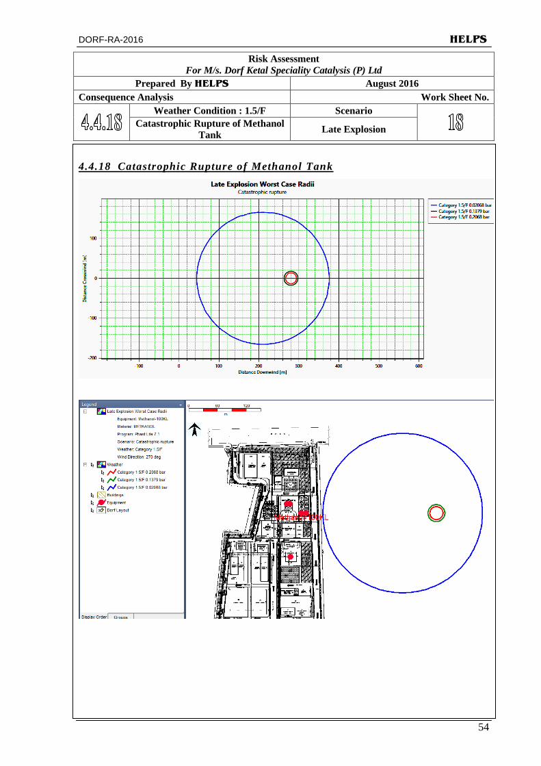
DORF-RA-2016 HELPS
54
Risk Assessment For M/s. Dorf Ketal Speciality Catalysis (P) Ltd
Prepared By HELPS August 2016 Consequence Analysis Work Sheet No.
Weather Condition : 1.5/F Scenario
Catastrophic Rupture of Methanol Tank Late Explosion
4.4.18 Catastrophic Rupture of Methanol Tank

DORF-RA-2016 HELPS
55
Risk Assessment For M/s. Dorf Ketal Speciality Catalysis (P) Ltd
Prepared By HELPS August 2016 Consequence Analysis Work Sheet No.
Weather Condition : 1.5/F Scenario Leak from Methanol Tank Early Poor Fire
4.4.19 Leak from Methanol Tank

DORF-RA-2016 HELPS
56
Risk Assessment For M/s. Dorf Ketal Speciality Catalysis (P) Ltd
Prepared By HELPS August 2016 Consequence Analysis Work Sheet No.
Weather Condition : 1.5/F Scenario Leak from Methanol Tank Late Pool Fire
4.4.20 Leak from Methanol Tank

DORF-RA-2016 HELPS
57
Risk Assessment For M/s. Dorf Ketal Speciality Catalysis (P) Ltd
Prepared By HELPS August 2016 Consequence Analysis Work Sheet No.
Weather Condition : 1.5/F Scenario
Catastrophic Rupture of Methyl Ethyl Ketone Tank Late Pool Fire
4.4.21 Catastrophic Rupture of Methyl Ethyl Ketone Tank

DORF-RA-2016 HELPS
58
Risk Assessment For M/s. Dorf Ketal Speciality Catalysis (P) Ltd
Prepared By HELPS August 2016 Consequence Analysis Work Sheet No.
Weather Condition : 1.5/F Scenario
Catastrophic Rupture of Methyl Ethyl Ketone Tank Late Explosion
4.4.22 Catastrophic Rupture of Methyl Ethyl Ketone Tank

DORF-RA-2016 HELPS
59
Risk Assessment For M/s. Dorf Ketal Speciality Catalysis (P) Ltd
Prepared By HELPS August 2016 Consequence Analysis Work Sheet No.
Weather Condition : 1.5/F Scenario
Leak from Methyl Ethyl Ketone Tank Early Poor Fire
4.4.23 Leak from Methyl Ethyl Ketone Tank

DORF-RA-2016 HELPS
60
Risk Assessment For M/s. Dorf Ketal Speciality Catalysis (P) Ltd
Prepared By HELPS August 2016 Consequence Analysis Work Sheet No.
Weather Condition : 1.5/F Scenario
Leak from Methyl Ethyl Ketone Tank Late Pool Fire
4.4.24 Leak from Methyl Ethyl Ketone Tank
DORF-RA-2016 HELPS
61
5.15.15.15.1 PRELIMINARY THREAT IDENTIFICATIONPRELIMINARY THREAT IDENTIFICATIONPRELIMINARY THREAT IDENTIFICATIONPRELIMINARY THREAT IDENTIFICATION
Threat ident if icat ion is the stage where equipment and operat ions
that have the potent ial to do harm are ident if ied. Threats can be to
damage of equipment stor ing or processing hazardous substances or
operat ions that have the potent ia l to lead to a release of hazardous
mater ia l and possible ignit ion result ing in f i re, or explosion. In order
to calculate the effects of incidents, computer based models are
used when the l ikel ihood and consequence of incidents are
evaluated, they can be combined to produce a numerical recantat ion
of the r isk.
The level of r isk can be represented in a number of ways. Two of the
most useful ways in this context are indiv idual and societa l r isk .
5.1.1 Individual Risk :
Indiv idual r isk is the r isk of a nominated adverse effect, usual ly
fata l i ty, i f an indiv idual remained f ixed at a locat ion for a set
t ime, usual ly a year, adjacent to an industr ia l hazard. Indiv idual
r isk contours are der ived by calculat ing at a specif ic locat ion,
the impacts result ing from each fa i lure mode identi f icat ion and
summing the r isk value associated with each fa i lure mode.
Indiv idual r isk cr iteria can be presented as a diagram, known as
the “Dagger Diagram”, to faci l i tate understanding. F igure 1
given next page shows the individual r isks of fata l i ty, and some
r isks experienced in day to day l i fe.

DORF-RA-2016 HELPS
62
5.1.2 Societal Risk :
Societa l r isk cr i ter ia specify levels of societal r isk that must not
be exceeded by a part icular act iv ity. These cr iter ia ensure that
a hazardous act iv ity / faci l i ty does not impose a r isk on society
that is disproport ionate to other major hazards hav ing regard
to the benef i t the act iv ity or faci l i ty br ings. In part icular,
societal r isk cr iter ia are used to regulate the r isks of an
accident involv ing many fata l i t ies, which indiv idual r isk cr i ter ia
do not address.
Societa l r isk cr iter ia are usual ly expressed in the form of a
chart, with N, the number of fata l i t ies across the bottom and
the frequency of N or more fata l i t ies on the vert ical scale. The
cri ter ia are areas, or zones on the chart, del ineated by
downward s loping l ines.
Risk per year of Fatality
10 -3
10 -6
Unacceptable
Region
Figure – 1 : ALARP Diagram
Tolerable ALARP region
Risk is taken only if a
benefit is required
Broadly Acceptable
Region
Tolerable only if risk reduction is
impracticable of if its cost is
grossly disproportionate to the
improvement gained
Risk cannot be justified
save in extraordinary
circumstances
Tolerable if cost of reduction
would exceed the improvement
Necessary to maintain
assurance that risk remains at
this level
High Risk
Low Risk

DORF-RA-2016 HELPS
63
The cri ter ia l ines shown slope downwards ref lect ing how the
cri ter ia demands decreasing f requency as sever ity increases.
Refer F igure 2 below :
5.25.25.25.2 OFF OFF OFF OFF ---- SITE ACCIDENT INITIATORS SITE ACCIDENT INITIATORS SITE ACCIDENT INITIATORS SITE ACCIDENT INITIATORS
The method of measur ing the f requency of accidents caused by Off-
Site Events should be f it for purpose. In other words i t should be
proport ionate to the level of r isk. Thus, i f a s ite is located far away
from any ai rport or f l ight path (mil i tary or civ i l ), then i t is acceptable
for the safety report to refer to the background crash rate for the UK.
On the other hand, i f the s ite is located close to a busy a i rport then
a much more detai led assessment of ai rcraft impact should be
carr ied out.
Figure - 2
10 -5
10 -6
10 -4
10 -3
10 -7
10 -8
1 10 100 1000
Number of Fatalities (N)
Fre
quen
cy o
f N o
r m
ore
Fat
aliti
es p
er y
ear
ALARP
Negligible
Unacceptable

DORF-RA-2016 HELPS
64
5.2.1 Table 1
Initiator Method of Model
Aircraft impact AEA methodology
Seismic event geological survey data
Lightning strike Electricity council data and methodology
Severe environmental conditions:- Abnormal rainfall Abnormal snow fall Very low temperature High temperature Gale force winds
Historical data plus reasoned argument
Flooding Site and met office data plus reasoned argument
Subsidence Historical data plus reasoned argument
Land slip Historical data plus reasoned argument
Fire or explosion at adjoining plant Site environs information plus relevant data where relevant
Missile from Off-Site Site environs information plus relevant data
Hazardous substance pipeline rupture Site environs information plus relevant data
Collapse of high voltage cable Site environs information plus relevant data
Impact by out of control road or rail vehicle Site environs information plus relevant data
5.2.2 Possible Major Accident Scenario
Plant Item Failure Accident Scenarios
Storage or Transport Vessel
Catastrophic failure
Flammable/ Toxic gas cloud
Hole in vessel wall
Flammable/Toxic gas cloud
Filling line
Rupture
Flammable / Toxic gas cloud
Puncture
Flammable / Toxic gas cloud
Small hole
Flammable / Toxic gas cloud
Flange leak
Export line
Rupture
Flammable / Toxic gas cloud
Puncture
Flammable / Toxic gas cloud
Small hole
Flammable / Toxic gas cloud
Flange leak
Process Equipment, Compressors, liquefied, vaporisers Pumps
Disintegration
Toxic gas cloud
Leak
Toxic gas cloud
Loss of control
Flammable / Toxic gas cloud
Explosion
Abatement Equipment
Disintegration
Toxic gas cloud
Leak
Toxic gas cloud
Loss of control
Flammable / Toxic gas cloud
Overload
Flammable / Toxic gas cloud

DORF-RA-2016 HELPS
65
5.2.3 Probable Accident Initiators
Off-site Events Operator Error Abnormal Load Arson or Sabotage
Inadequate Management Loss of Service
Aircraft impact system opened impact by vehicle fire corrosion Loss of electricity.
Seismic event filled when not closed
impact by missile explosion erosion loss of cooling water.
Subsidence system overfilled impact by dropped load valve opened vibration failure of
process controls. loss of nitrogen
Extreme environmental
conditions abnormal rain fall abnormal snow
fall very low
temperature high temperature
flooding gale force winds lightening strike
containment degraded.
internal temperature or
pressure outside design limit.
safety system degraded. cyclic load loss of
compressed air
Vehicle/train impact excess load
external temp/ pressure outside
design limit. contamination
inadequate materials or specification.
loss of steam
Land slip failure to respond
correctly to an alarm.
pressurisation. control system degraded.
chemical attack
Explosion incorrect valve action.
under pressure containment system degraded.
hidden defect in containment
system.
Fire Contamination failure to detect
dangerous situation.
Missile Loss of control failure of process controls.
5.35.35.35.3 RISK LEVELRISK LEVELRISK LEVELRISK LEVEL
5.3.1 Interpretation for Risk to Workers :
The quant itat ive r isk assessment depends upon quant ity,
property, physical form, durat ion and frequency of handl ing
and air borne concentrat ion of the main hazardous raw
mater ia ls. R isk Assessment is based on comparison with
acceptable points and r isk formula is g iven in para 5.6.
DORF-RA-2016 HELPS
66
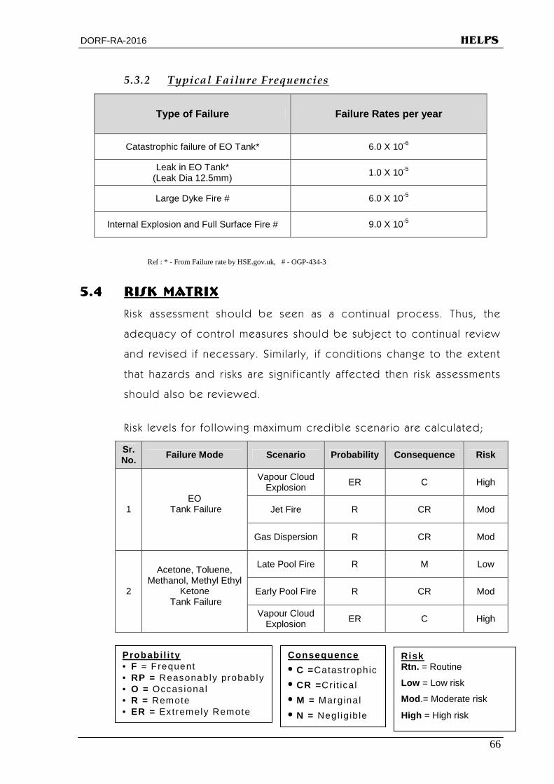
5.3.2 Typical Failure Frequencies
Type of Failure Failure Rates per year
Catastrophic failure of EO Tank* 6.0 X 10⁻⁶
Leak in EO Tank* (Leak Dia 12.5mm)
1.0 X 10⁻⁵
Large Dyke Fire # 6.0 X 10⁻⁵
Internal Explosion and Full Surface Fire # 9.0 X 10⁻⁵
Ref : * - From Failure rate by HSE.gov.uk, # - OGP-434-3
5.45.45.45.4 RISK MATRIXRISK MATRIXRISK MATRIXRISK MATRIX
Risk assessment should be seen as a cont inual process. Thus, the
adequacy of control measures should be subject to cont inual rev iew
and rev ised if necessary. S imi lar ly , i f condit ions change to the extent
that hazards and r isks are signif icant ly af fected then r isk assessments
should also be reviewed.
R isk levels for fol lowing maximum credible scenar io are calculated;
Sr. No. Failure Mode Scenario Probability Consequence Risk
Vapour Cloud Explosion
ER C High
Jet Fire R CR Mod 1 EO
Tank Failure
Gas Dispersion R CR Mod
Late Pool Fire R M Low
Early Pool Fire R CR Mod 2
Acetone, Toluene, Methanol, Methyl Ethyl
Ketone Tank Failure
Vapour Cloud Explosion
ER C High
Probabi l i ty • F = Frequent • RP = Reasonably probably • O = Occas ional • R = Remote • ER = Extremely Remote • I = Imposs ible
Consequence
•••• C =Catastrophic
•••• CR =Cr it ica l
•••• M = Marginal
•••• N = Negl ig ib le
Risk Rtn. = Routine
Low = Low risk
Mod .= Moderate risk
High = High risk
DORF-RA-2016 HELPS
67
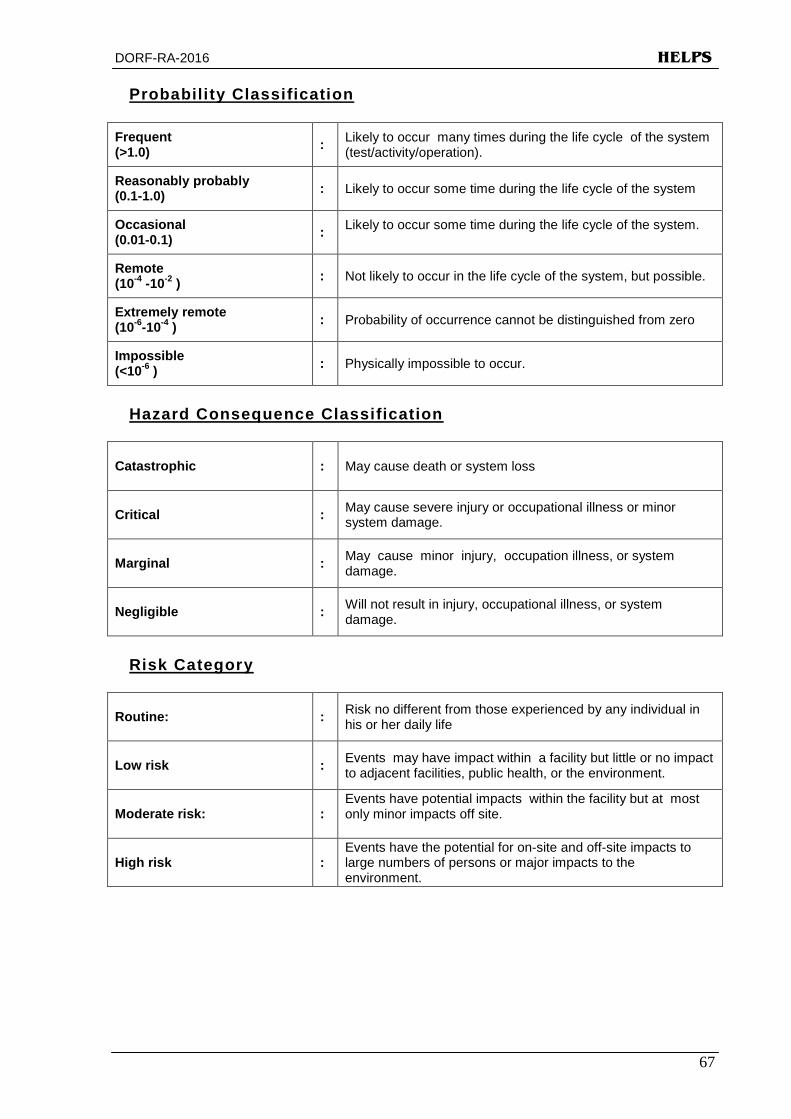
Probabil i ty Classification
Frequent (>1.0) : Likely to occur many times during the life cycle of the system
(test/activity/operation).
Reasonably probably (0.1-1.0) : Likely to occur some time during the life cycle of the system
Occasional (0.01-0.1) : Likely to occur some time during the life cycle of the system.
Remote (10-4 -10-2 ) : Not likely to occur in the life cycle of the system, but possible.
Extremely remote (10-6-10-4 ) : Probability of occurrence cannot be distinguished from zero
Impossible (<10-6 ) : Physically impossible to occur.
Hazard Consequence Classification
Catastrophic : May cause death or system loss
Critical : May cause severe injury or occupational illness or minor system damage.
Marginal : May cause minor injury, occupation illness, or system damage.
Negligible : Will not result in injury, occupational illness, or system damage.
Risk Category
Routine: : Risk no different from those experienced by any individual in his or her daily life
Low risk : Events may have impact within a facility but little or no impact to adjacent facilities, public health, or the environment.
Moderate risk: : Events have potential impacts within the facility but at most only minor impacts off site.
High risk : Events have the potential for on-site and off-site impacts to large numbers of persons or major impacts to the environment.

DORF-RA-2016 HELPS
68
5.55.55.55.5 HISTORY OF PAST ACCIDENTSHISTORY OF PAST ACCIDENTSHISTORY OF PAST ACCIDENTSHISTORY OF PAST ACCIDENTS
Knowledge and Safety measures are tested when any incident /
happening takes place which teaches us a lessons and we are
compelled to acquire the knowledge of the causes of the accidents
and of preventat ive measures to prevent its reoccurrences.
The management is mainta in ing records in respect of recorded
reportable accident detai ls. Past Accident History is g iven in
Annexure-11.
5.65.65.65.6 LIMITATIONS & UNCERTAINTYLIMITATIONS & UNCERTAINTYLIMITATIONS & UNCERTAINTYLIMITATIONS & UNCERTAINTY
The hazard ident if icat ion procedures are coupled with good
engineer ing judgement, regulat ions, and guidel ines together
const itute a better st rategy to ensur ing safety. The accuracy and
usefulness of r isk assessment are cr it ical ly dependent on the qual ity
of the model assumptions and that of the relevant database. In case
of accident f requency assessment, the sources of errors are a lso
varied. In many instances only very general data are avai lable on
equipment fa i lure, for which stat ist ical accuracy is often poor. In
other cases, these may be very l i t t le data avai lable at a l l . In India, the
databases on equipment fai lure and human error are not readily
avai lable. There is indeed a st rong need to bui ld up a nat ional
rel iabi l i ty database through co-operat ive ef fects between industry
and instrument / equipment manufactures.
DORF-RA-2016 HELPS
69
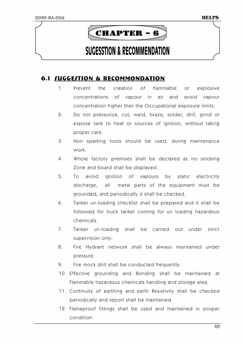
6.16.16.16.1 SUGGESTION & RECOMMONDATIONSUGGESTION & RECOMMONDATIONSUGGESTION & RECOMMONDATIONSUGGESTION & RECOMMONDATION
1. Prevent the creat ion of f lammable or explosive
concentrat ions of vapour in ai r and avoid vapour
concentrat ion higher than the Occupat ional exposure l imits.
2. Do not pressur ize, cut, weld, braze, solder, dr i l l , gr ind or
expose tank to heat or sources of ignit ion, without tak ing
proper care.
3. Non spark ing tools should be used, dur ing maintenance
work.
4. Whole factory premises shal l be declared as no smoking
Zone and board shal l be displayed.
5. To avoid ignit ion of vapours by stat ic electr ici ty
discharge, a l l metal parts of the equipment must be
grounded, and per iodical ly i t shal l be checked.
6. Tanker un- loading checkl ist shal l be prepared and it shal l be
fol lowed for t ruck tanker coming for un loading hazardous
chemicals.
7. Tanker un- loading shal l be carr ied out under str ict
superv ision only.
8. Fi re Hydrant network shal l be always maintained under
pressure.
9. Fi re mock dr i l l shal l be conducted frequent ly.
10. Effect ive grounding and Bonding shal l be maintained at
F lammable hazardous chemicals handl ing and storage area.
11. Cont inuity of earthing and earth Resist iv ity shal l be checked
periodical ly and report shal l be mainta ined.
12. Flameproof f it t ings shal l be used and mainta ined in proper
condit ion.

DORF-RA-2016 HELPS
70
13. All operator wear appropriate PPE whi le work ing that shal l be
ensured.
14. Operators should be tra ined for the hazardous propert ies and
control measures of chemicals which are us ing in the
insta l lat ion.
15.15.15.15. INSPECTION & MAINTENANCE INSPECTION & MAINTENANCE INSPECTION & MAINTENANCE INSPECTION & MAINTENANCE
The f requency for various act iv i t ies in the plant, process &
Storage are main l ined with attent ively by the management, as
per fol lowing:
Sr . Sr . Sr . Sr .
No.No.No.No. F requencyFrequencyFrequencyFrequency Inspect ion & Maintenance Act iv i tyInspect ion & Maintenance Act iv i tyInspect ion & Maintenance Act iv i tyInspect ion & Maintenance Act iv i ty
1 Dai ly
Inspect ion
Cr i t ica l equipments, controls, indicators, levels,
switches, sett ings, dra in va lves, leakages, storage tanks
& TLF
2 Week ly Inspect ion & maintenance of Pumps.
3 Monthly Breather Valve, F i re Protect ion System
4 Quarter ly Al l Indicators Alarms, t r ips & Cont rol
5 Hal f Year ly Ult rasonic Thickness Gauge, Earthing check
6 Annual Al l va lves, sa fety va lves, Pa int ing of vesse ls Pipe l ines.
16. Test & Examinat ion of Tanks, Pressure Vessels etc. a re to be
carr ied out & records in prescr ibed forms are mainta ined.
17. The M.S.D.S. of Hazardous Chemicals is to be prepared &
avai lable with the management.
18. Colour code system for pipe l ines shal l adopted as per IS
Colour Code System.
19. Safety t ra ining programmes shal l be organised for a l l level of
workers, superv isors including contract workers.
20. Fi re F ight ing tra in ing shal l be organised for al l employees.
21. SOP, Safety Instruct ion and caut ionary not ice shal l be
displayed at conspicuous locat ion.

DORF-RA-2016 HELPS
Annexure 71

DORF-RA-2016 HELPS
Annexure 72
Annexure – 1 LOCATION PLAN
DORF KETAL DORF KETAL DORF KETAL DORF KETAL
SPECIALITY CATALYSIS (P) LTD.SPECIALITY CATALYSIS (P) LTD.SPECIALITY CATALYSIS (P) LTD.SPECIALITY CATALYSIS (P) LTD. Plot No.Z/108, Dahej, Dist. Bharuch

DORF-RA-2016 HELPS
Annexure 73
Annexure – 2 LAY OUT PLAN
DORF KETAL DORF KETAL DORF KETAL DORF KETAL
SPECIALITY CATALYSIS (P) LTD.SPECIALITY CATALYSIS (P) LTD.SPECIALITY CATALYSIS (P) LTD.SPECIALITY CATALYSIS (P) LTD. Plot No.Z/108, Dahej, Dist. Bharuch
74 HELPS
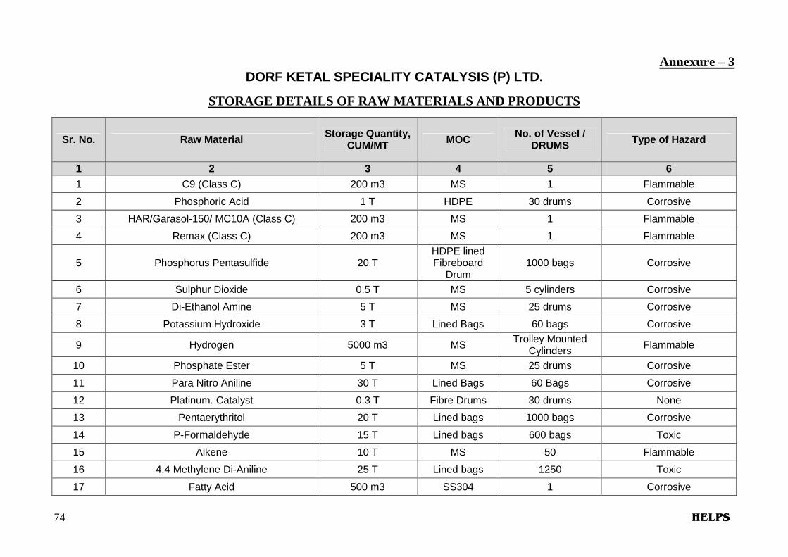
Annexure – 3 DORF KETAL SPECIALITY CATALYSIS (P) LTD.
STORAGE DETAILS OF RAW MATERIALS AND PRODUCTS
Sr. No. Raw Material Storage Quantity, CUM/MT MOC No. of Vessel /
DRUMS Type of Hazard
1 2 3 4 5 6
1 C9 (Class C) 200 m3 MS 1 Flammable
2 Phosphoric Acid 1 T HDPE 30 drums Corrosive
3 HAR/Garasol-150/ MC10A (Class C) 200 m3 MS 1 Flammable
4 Remax (Class C) 200 m3 MS 1 Flammable
5 Phosphorus Pentasulfide 20 T HDPE lined Fibreboard
Drum 1000 bags Corrosive
6 Sulphur Dioxide 0.5 T MS 5 cylinders Corrosive
7 Di-Ethanol Amine 5 T MS 25 drums Corrosive
8 Potassium Hydroxide 3 T Lined Bags 60 bags Corrosive
9 Hydrogen 5000 m3 MS Trolley Mounted Cylinders Flammable
10 Phosphate Ester 5 T MS 25 drums Corrosive
11 Para Nitro Aniline 30 T Lined Bags 60 Bags Corrosive
12 Platinum. Catalyst 0.3 T Fibre Drums 30 drums None
13 Pentaerythritol 20 T Lined bags 1000 bags Corrosive
14 P-Formaldehyde 15 T Lined bags 600 bags Toxic
15 Alkene 10 T MS 50 Flammable
16 4,4 Methylene Di-Aniline 25 T Lined bags 1250 Toxic
17 Fatty Acid 500 m3 SS304 1 Corrosive
75 HELPS
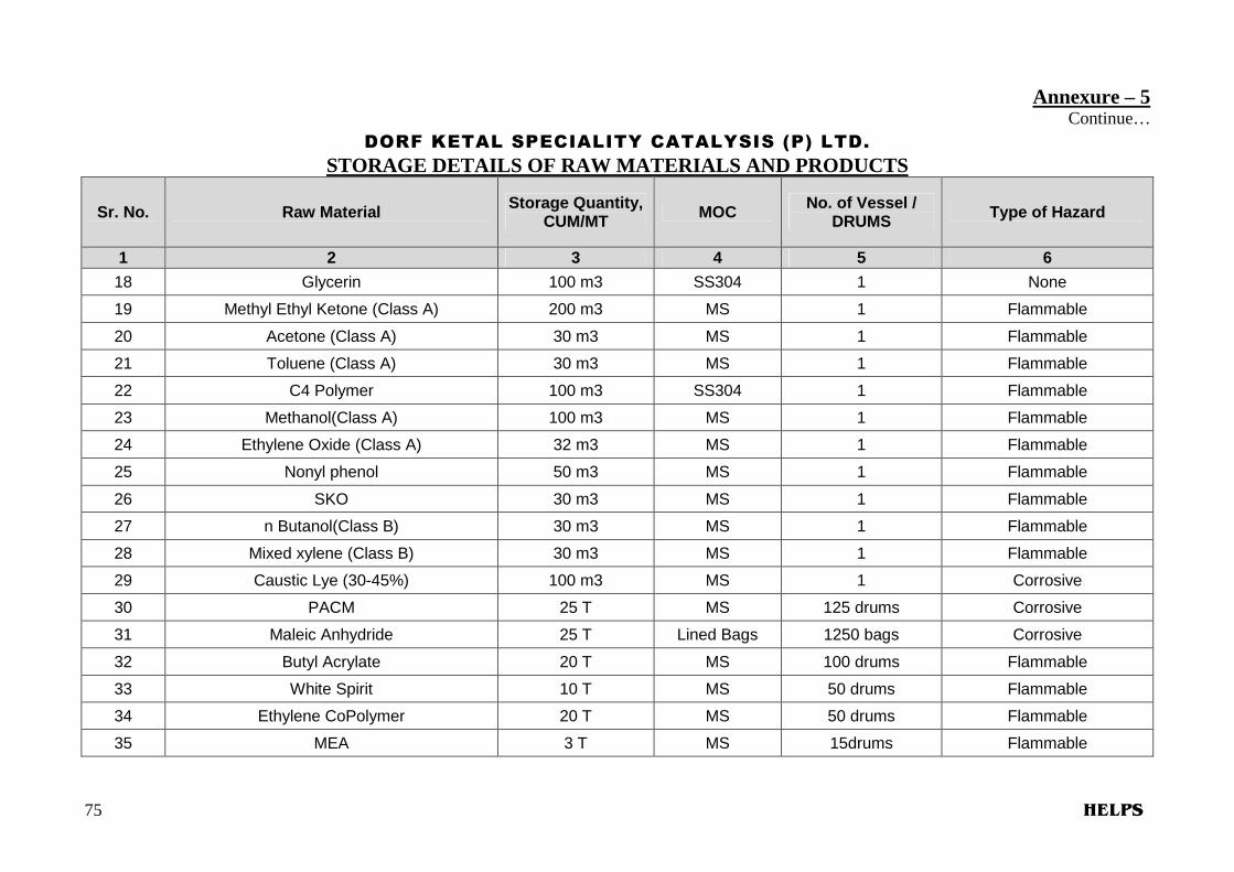
Annexure – 5 Continue…
DORF KETAL SPECIALITY CATALYSIS (P) LTD.
STORAGE DETAILS OF RAW MATERIALS AND PRODUCTS
Sr. No. Raw Material Storage Quantity, CUM/MT MOC No. of Vessel /
DRUMS Type of Hazard
1 2 3 4 5 6
18 Glycerin 100 m3 SS304 1 None
19 Methyl Ethyl Ketone (Class A) 200 m3 MS 1 Flammable
20 Acetone (Class A) 30 m3 MS 1 Flammable
21 Toluene (Class A) 30 m3 MS 1 Flammable
22 C4 Polymer 100 m3 SS304 1 Flammable
23 Methanol(Class A) 100 m3 MS 1 Flammable
24 Ethylene Oxide (Class A) 32 m3 MS 1 Flammable
25 Nonyl phenol 50 m3 MS 1 Flammable
26 SKO 30 m3 MS 1 Flammable
27 n Butanol(Class B) 30 m3 MS 1 Flammable
28 Mixed xylene (Class B) 30 m3 MS 1 Flammable
29 Caustic Lye (30-45%) 100 m3 MS 1 Corrosive
30 PACM 25 T MS 125 drums Corrosive
31 Maleic Anhydride 25 T Lined Bags 1250 bags Corrosive
32 Butyl Acrylate 20 T MS 100 drums Flammable
33 White Spirit 10 T MS 50 drums Flammable
34 Ethylene CoPolymer 20 T MS 50 drums Flammable
35 MEA 3 T MS 15drums Flammable

76 HELPS
Annexure – 6 DORF KETAL SPECIALITY CATALYSIS (P) LTD.
SALIENT PROPERTIES OF CERTAIN HAZARDOUS CHEMICALS
Physical & chemical composition B.P F.P LEL
UEL
Sp. Gr. (water = 1)at
V.D. at (air = 1)
No. of container & size Sr.
No. Raw
Materials Chemical Formula State 0 C 0 C %
TLV ppm or
mg/Nm 3
LD50, mg/Kg LC50 mg/l
200 C 200 C
Odor Thresh
old ppm or mg/m 3 MT / CUM
1 2 3 4 5 6 7 8 9 10 11 12
1 C9 Mixed
Hydrocarbons Liquid 150-270 32-66 1%, 7% NA
LD50- 346mg/kg to 5000, LC50-
18-54000 g/cum
0.9 3-5 NA 1no. x200 M3
2 Phosphoric
Acid H3PO4 Liquid 158 NA NA 1
LD50, 1530 mg/kg, LC50 >850 ppm/1h
1.685 3.4 NA 30 drums x 33kg
3 Garasol-150 NA Liquid 178 62 0.6% 7% NA LD50 > 6000
mg/kg 0.875 NA NA
1no. x 200 M3
4 MC-10A NA Liquid 178 62 0.6% 7% NA LD50 > 6000
mg/kg 0.875 NA NA
1no. x 200 M3
5 Phosphorus Pentasulfide
P2S5 Solid 515 >260 50gm/m
3 1mg/m3
LD50- 389mg/kg to
5000, 2 N.A. NA 1000bags x20kg
6 Sulphur Dioxide SO2 Gas -10 -75 N.A. 2ppm
LD50- 2520 ppm/kg 2.26 2.26 NA
5 cylinders x 0.1MT
7 Di-Ethanol
Amine C4H11NO2 Solid 268 168.9 - - 710 mg/kg 1.1 3.6 - 25 drums x 200kg
8 Potassium Hydroxide
KOH Solid N.A. N.A. N.A. N.A. LD50: 273
mg/kg 2.044 N.A. N.A. 60bags x 50kg
9 Hydrogen H2 Gas -253 N.A. 4%, 75% N.A. N.A. 0.069 0.07 N.A.
5000m3 trolley mounted cylinders
, 1 trolley =96/170/200
cylinders)

77 HELPS
Annexure – 6 Continue…
DORF KETAL SPECIALITY CATALYSIS (P) LTD.
SALIENT PROPERTIES OF CERTAIN HAZARDOUS CHEMICALS
Physical & chemical composition B.P F.P LEL
UEL
Sp. Gr. (water = 1)at
V.D. at (air = 1)
No. of container & size Sr.
No. Raw
Materials Chemical Formula State 0 C 0 C %
TLV ppm or
mg/Nm 3
LD50, mg/Kg LC50 mg/l
200 C 200 C
Odor Thresh
old ppm or mg/m 3 MT / CUM
1 2 3 4 5 6 7 8 9 10 11 12
10 Para Nitro
Aniline C6H5NH2 Solid 332 199 N.A. 3 ppm 450 mg/kg 1.42 4.77 NA 60bags x 500kg
11 Pt. Catalyst N.A. Solid N.A. N.A. N.A. N.A. NA N.A. N.A. N.A. 30drums x 10kg
12 Pentaerythritol C5H12O4 Solid 276 N.A. N.A. 20mg/m3 LD 18500
mg/kg, 1.396 4.7 N.A. 1000bags x 20kg
13 Formaldehyde HCHO Liquid 98 50-60 6 –
36.5% 0.3 ppm
LD50-42 mg/kg,
1.08 1.03 100 ppm
600bags x 25kg
14 Alkene Alkene Liquid 291-302 79 0.9 - NA NA 0.73 4.35 NA 50 drums x 200kg
15 4,4 Methylene
Di-Aniline C13H14N2
Solid 242 230 N.A. 1 ppm
LD50 = 264 mg/kg
1.056 6.8 NA 1250bags x 20kg
16 Fatty Acid NA Liquid >200 200 NA N.A. N.A. 0.905 NA N.A. 1 no. x 500m3
17 Glycerin C3-H8-O3 Liquid 290 160 NA 15 LD50, 4090 mg/kg, LC50 >570 ppm/1h
1.263 3.17 NA 1 no. x 100m3
18 Methyl Ethyl
Ketone C8-H18-O6 Liquid 80 -6 1.9% - 11.5% NA
LD50, 2740-5600 mg/kg, LC50 11700
ppm/4h
0.81 2.41 2-85 1 no. x 200m3
19 Acetone CH3COCH3 Liquid 56.5 -9 2.2 13.0
500 5800 mg/kg, LC50, 50100
mg/m3 0.791 2.0
24-1615
1 no. x 30m3
20 Toluene C6-H5-CH3 or
C7-H8 Liquid 110.6 4.4
1.1%, 7.1%
50ppm LD50, 636
mg/kg, LC50 440 ppm/24h
0.863 3.1 1.6 1 no. X 30m3
78 HELPS
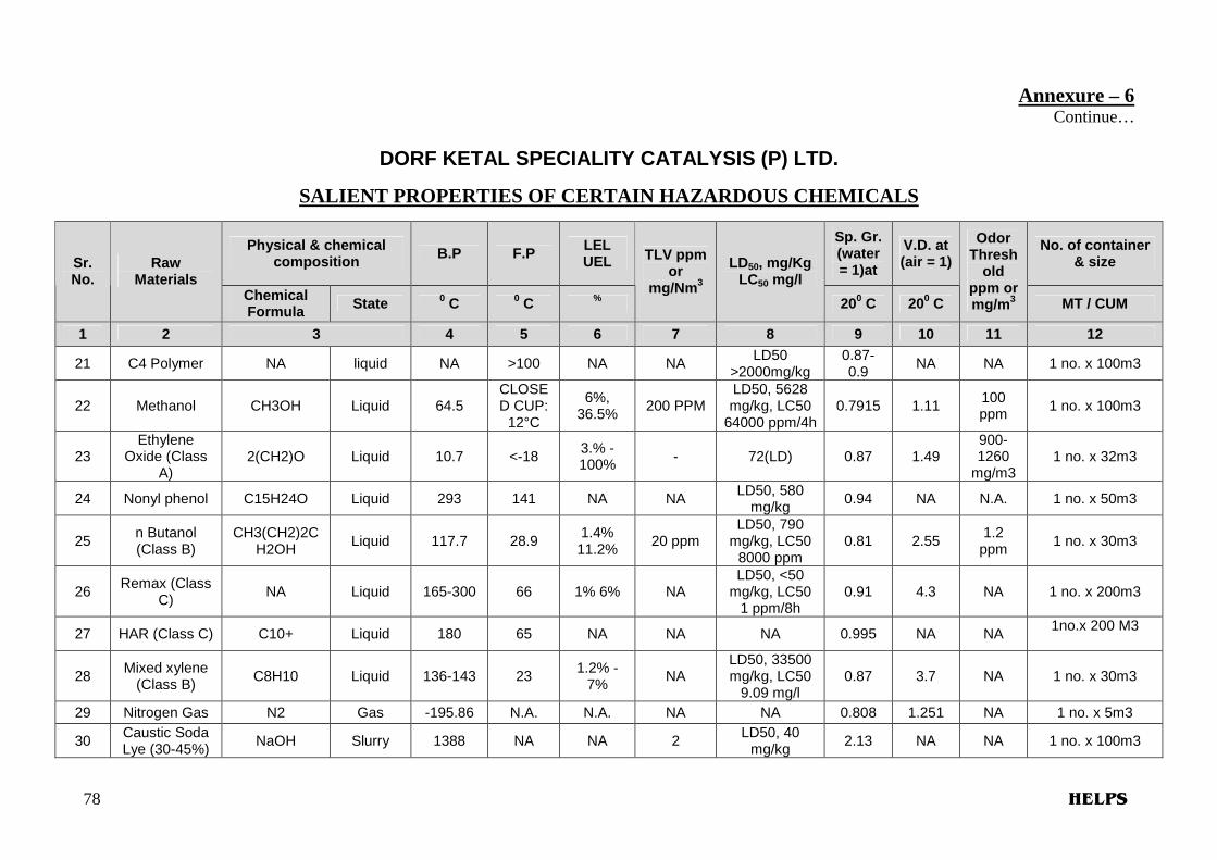
Annexure – 6 Continue…
DORF KETAL SPECIALITY CATALYSIS (P) LTD.
SALIENT PROPERTIES OF CERTAIN HAZARDOUS CHEMICALS
Physical & chemical composition B.P F.P LEL
UEL
Sp. Gr. (water = 1)at
V.D. at (air = 1)
No. of container & size Sr.
No. Raw
Materials Chemical Formula State 0 C 0 C %
TLV ppm or
mg/Nm 3
LD50, mg/Kg LC50 mg/l
200 C 200 C
Odor Thresh
old ppm or mg/m 3 MT / CUM
1 2 3 4 5 6 7 8 9 10 11 12
21 C4 Polymer NA liquid NA >100 NA NA LD50
>2000mg/kg 0.87-0.9
NA NA 1 no. x 100m3
22 Methanol CH3OH Liquid 64.5 CLOSED CUP:
12°C
6%, 36.5%
200 PPM LD50, 5628 mg/kg, LC50
64000 ppm/4h 0.7915 1.11
100 ppm
1 no. x 100m3
23 Ethylene
Oxide (Class A)
2(CH2)O Liquid 10.7 <-18 3.% - 100% - 72(LD) 0.87 1.49
900-1260
mg/m3 1 no. x 32m3
24 Nonyl phenol C15H24O Liquid 293 141 NA NA LD50, 580
mg/kg 0.94 NA N.A. 1 no. x 50m3
25 n Butanol (Class B)
CH3(CH2)2CH2OH
Liquid 117.7 28.9 1.4% 11.2%
20 ppm LD50, 790
mg/kg, LC50 8000 ppm
0.81 2.55 1.2
ppm 1 no. x 30m3
26 Remax (Class
C) NA Liquid 165-300 66 1% 6% NA
LD50, <50 mg/kg, LC50
1 ppm/8h 0.91 4.3 NA 1 no. x 200m3
27 HAR (Class C) C10+ Liquid 180 65 NA NA NA 0.995 NA NA 1no.x 200 M3
28 Mixed xylene
(Class B) C8H10 Liquid 136-143 23
1.2% - 7%
NA LD50, 33500 mg/kg, LC50
9.09 mg/l 0.87 3.7 NA 1 no. x 30m3
29 Nitrogen Gas N2 Gas -195.86 N.A. N.A. NA NA 0.808 1.251 NA 1 no. x 5m3
30 Caustic Soda Lye (30-45%)
NaOH Slurry 1388 NA NA 2 LD50, 40
mg/kg 2.13 NA NA 1 no. x 100m3

79 HELPS
Annexure – 6 Continue…
DORF KETAL SPECIALITY CATALYSIS (P) LTD.
SALIENT PROPERTIES OF CERTAIN HAZARDOUS CHEMICALS
Physical & chemical composition B.P F.P LEL
UEL
Sp. Gr. (water = 1)at
V.D. at (air = 1)
No. of container & size Sr.
No. Raw
Materials Chemical Formula State 0 C 0 C %
TLV ppm or
mg/Nm 3
LD50, mg/Kg LC50 mg/l
200 C 200 C
Odor Thresh
old ppm or mg/m 3 MT / CUM
1 2 3 4 5 6 7 8 9 10 11 12
31 Butyl Acrylate C7H12O2 Liquid 145 NA 1.3 – 1.7 9.4 -9.9
NA
LD50 1780mg/kg LC50 7800
mg/m
0.889 NA NA 100drums x 200kg
32 Maleic
Anhydride C4H2O3 Solid 202 102 NA 0.25 ppm NA 1.5 3.4 NA 1250bags x 20kg
33 White Spirt NA Liquid 130-144 21-30 0.6-6.5 NA NA 0.78 4.5-5 0.5-5 50drums x 200kg
34 MEA
H2N-CH2CH2OH
Liquid 171 96 5 % 17% 3ppm
LD50 1000mg/kg LC50 2000
mg/kg
1.02 2.1 NA 15drums X 200kg
35 PACM NA Liquid 320 >100 NA NA LD50 625
mg.kg 0.96 7.24 NA 125drums x 200kg
36 Ethylene
CoPolymer Solid N.A. >62
0.6% 6.5%
NA LD50 >2000
mg/kg 0.91 NA NA 50drums x 400kg
N.A. Not Applicable, NA Not Available

AARREEAA OOFF SSPPEECCIIAALLIISSAATTIIOONN
Other Services
Competent Persons Under Factories Act, recognized by Director
Industrial Safety & Health, Gujarat State, For Test, Examination & Certification
• Stability Certificate for Buildings and Plants – Section 6 & 112, Rule 3C
• Pressure Vessels & Plants– Section 31, Rule 61
• Lifts & Hoists – Section 28, Rule58
• Lifting Machines, Ropes and Lifting Tackles – Section 29, Rule 60
• Centrifugal Machines / Power Press – Section 21, Rule54
• Thermic Fluid Heater – Rule 68D
• Oven & Driers – Rule 68G
• Ventilation System(Fume Extraction System) – Section 87, Schedule under Rule 102
Third Party Safety Audit
Fire Audit
Environmental Audit
Energy Audit
Electrical Audit
Specialized Audits
Valuation of Immovable
Properties,
Machineries, Buildings
On-Site Emergency Plan, Off-Site Emergency Plan, Disaster Management Plan
Safety Reports (In Schedule-8)
Schedule – 7
Risk Assessment / Risk Analysis by DNV Phast
HAZOP & HAZAN Studies
Safety Manual
Health, Safety & Environment Policy
Disclosure of Information to Workers, Authorities & General Public
Drawing preparation work for DISH approval
DISH Approved Training Institute under Section 111/A
Need based Industrial Safety Training Programmes
Chartered Engineer’s Certification Work
M.S.D.S.
Investigation Report on Industrial Accidents
Consultancy on Factories Act with Factories Rules
Mock drill / Exercise on Industrial Emergency Plan