Embed Size (px)
Citation preview
December 2013
NATURAL GAS PIPELINE
PLAN OF DEVELOPMENT
Donlin Gold Project

Natural Gas Pipeline PLAN OF DEVELOPMENT
Donlin Gold Project
Revision 1 December 2013
4720 Business Park Blvd. Suite G-25 Anchorage, Alaska 99503
Prepared By:
SRK Consulting (US), Inc. 4700 Business Park Blvd. Suite E-12
Anchorage, Alaska 99503

Plan of Development Donlin Gold Project Table of Contents
Donlin Gold i December 2013
TABLE OF CONTENTS 1.0 Introduction .............................................................................................................1-1 2.0 Purpose and Need ..................................................................................................2-1
2.1 Purpose .........................................................................................................2-1 2.2 Need ..............................................................................................................2-1 2.3 Background Information on Proposed Mine ...................................................2-1 2.4 Expected Public Benefits ...............................................................................2-2
3.0 Project Description .................................................................................................3-1 3.1 Commodity to be Transported and Purpose ...................................................3-3 3.2 Pipe to be used for Transportation of Natural Gas .........................................3-4 3.3 Timeline of Proposed Project .........................................................................3-5
3.3.1 Planned Commencement Date for Construction .................................3-5 3.3.2 Estimated Construction Time ..............................................................3-7 3.3.3 Planned Commencement Date for Operation .....................................3-8 3.3.4 Duration of Pipeline Operation ............................................................3-8
3.4 Estimated Employees ....................................................................................3-9 3.5 Financing Requirements for the Proposed Project ....................................... 3-10
3.5.1 Corporate Organization Structure ..................................................... 3-10 3.6 Natural Gas Transmission Line .................................................................... 3-11 3.7 Surface and Subsurface Attributes ............................................................... 3-12 3.8 Length/Width of ROW Area Needed for Related Activities ........................... 3-13 3.9 Ancillary to an Existing Right-of-Way ........................................................... 3-13 3.10 Route Description and Alternate Routes Considered ................................... 3-13
3.10.1 Pipeline ............................................................................................ 3-13 3.10.2 Proposed Pipeline Route Description ............................................... 3-15 3.10.3 Beluga Mountain Alternates .............................................................. 3-17 3.10.4 Little Mt. Susitna Alternates .............................................................. 3-17 3.10.5 Round Mountain Alternates .............................................................. 3-17 3.10.6 Goodman Pass Alternates ................................................................ 3-17 3.10.7 Egypt Mountain Alternate ................................................................. 3-18 3.10.8 St. John’s Hill Alternate .................................................................... 3-18 3.10.9 Windy Fork Alternate ........................................................................ 3-18 3.10.10 Big River Alternate ........................................................................ 3-18 3.10.11 Tatlawiksuk River Alternates ......................................................... 3-18 3.10.12 Kuskokwim River Alternates ......................................................... 3-18 3.10.13 Moose Creek Alternates ............................................................... 3-19 3.10.14 Kuskokwim Hills Alternates ........................................................... 3-19 3.10.15 Rainy Pass Alternate .................................................................... 3-19 3.10.16 Jones Alternate ............................................................................. 3-20 3.10.17 East Theodore Alternate ............................................................... 3-22 3.10.18 Beluga Alternate ........................................................................... 3-22 3.10.19 Pretty Creek Alternate................................................................... 3-22 3.10.20 Alternate Routes Assessment for the Electric Transmission Line .. 3-23
3.11 Safeguards for Persons, Property, Public and the Environment ................... 3-39
Plan of Development Donlin Gold Project Table of Contents
Donlin Gold ii December 2013
3.11.1 Safety of Workers ............................................................................. 3-39 3.11.2 Public Health and Safety .................................................................. 3-40 3.11.3 Public or Private Property ................................................................. 3-42 3.11.4 Vegetation or Timber ........................................................................ 3-43 3.11.5 Fish or Other Wildlife or Their Habitat ............................................... 3-44 3.11.6 Restoring Areas of Vegetation or Timber .......................................... 3-45 3.11.7 Erosion and Rehabilitation of Areas Eroded ..................................... 3-45 3.11.8 Quality Control and Procedures for Inspecting and Testing the
Pipeline ............................................................................................ 3-47 3.11.9 Special Safeguards to Protect the Interests of Individuals Living in
the General Area for Subsistence Purposes ..................................... 3-48 3.11.10 Special Safeguards to Protect the Interests of Commercial
Lodges ............................................................................................. 3-49 4.0 Right-of-Way Location (ROW) ................................................................................4-1
4.1 Legal Description ...........................................................................................4-1 4.2 Site-specific Engineering Surveys for Critical Areas .......................................4-1 4.3 River Crossings ..............................................................................................4-1 4.4 Calculation of Estimated Right-of-Way Acreage .............................................4-3
5.0 Pipeline Design Factors .........................................................................................5-1 5.1 Technical Summary .......................................................................................5-1 5.2 Toxicity of Pipeline Product ............................................................................5-2 5.3 Anticipated Operating Temperatures ..............................................................5-3 5.4 Depth of Pipeline ............................................................................................5-3 5.5 Permanent Width or Size ...............................................................................5-4 5.6 Temporary Areas Needed ..............................................................................5-4
6.0 Additional Right-of-Way Components ...................................................................6-1 6.1 Connection to Existing Right-of-Way ..............................................................6-1 6.2 Existing Components on or off Public Land ....................................................6-1 6.3 Possible Future Components .........................................................................6-1 6.4 Location and Description of Compressor Station ............................................6-1 6.5 Location and Description of Electric Transmission Line ..................................6-2 6.6 Location and Description of Fiber Optic Cable and Repeater Station .............6-4 6.7 Location and Description of Sand and Gravel Borrow Sites ...........................6-4 6.8 Location and Description of Pig Launcher/Receiver Facilities ........................6-4 6.9 Location and Description of Metering Stations ...............................................6-5 6.10 Location and Description of Mainline Block Valves ........................................6-7 6.11 Location and Description of Pipeline Markers.................................................6-8 6.12 Location and Description of Pipeline Cathodic Protection Test Stations .........6-8
7.0 Government Agency Involvement .........................................................................7-1 7.1 Entities that have Regulatory Authority or would be affected by the
Proposed Project ...........................................................................................7-1 7.2 Communications Protocol ..............................................................................7-2
7.2.1 State Agency Coordination .................................................................7-2 7.2.2 Federal Agency Coordination .............................................................7-2
Plan of Development Donlin Gold Project Table of Contents
Donlin Gold iii December 2013
7.3 List of Project Authorizations ..........................................................................7-4 7.3.1 State ROW Lease Required Documents ............................................7-4
8.0 Construction of Facilities .......................................................................................8-1 8.1 Construction Planning Considerations ...........................................................8-1
8.1.1 Iditarod Trail .......................................................................................8-1 8.1.2 Remote Cabins/Residential Areas ......................................................8-4 8.1.3 Active Faults .......................................................................................8-4 8.1.4 Wetlands and Waterbodies .................................................................8-5 8.1.5 Access and Existing Roads and Trails ................................................8-6 8.1.6 Susitna Flats State Game Refuge ......................................................8-6 8.1.7 Construction Communications and Public Outreach ...........................8-7 8.1.8 Invasive Species ................................................................................8-7 8.1.9 Visual Resource Management ............................................................8-7 8.1.10 Fish, Wildlife and Plant Concerns .......................................................8-7 8.1.11 Paleontological and Cultural Resource Sites ......................................8-8 8.1.12 Encountering Unforeseen Conditions .................................................8-8 8.1.13 Blasting and Transport of Explosives ..................................................8-8 8.1.14 Fire and Wildfire Response ................................................................8-9 8.1.15 Fueling ...............................................................................................8-9 8.1.16 Dust Control .......................................................................................8-9 8.1.17 Snow Management and Storage ........................................................8-9 8.1.18 Safety and Security .......................................................................... 8-10
8.2 Construction Execution ................................................................................ 8-11 8.2.1 Overview of Construction Execution ................................................. 8-12 8.2.2 Construction Execution Sequence .................................................... 8-14
8.3 Preparation for Construction ........................................................................ 8-17 8.3.1 Land Requirements and Construction Variances .............................. 8-17 Land Requirements ...................................................................................... 8-17 8.3.2 Flagging or Staking the Construction Area ....................................... 8-20 8.3.3 Barrier Delineation ............................................................................ 8-20 8.3.4 Vegetation Clearing and Grading ...................................................... 8-20 8.3.5 Make-up Area, Working Side and Travel Lane ................................. 8-21 8.3.6 Temporary Stormwater Control......................................................... 8-26 8.3.7 Pipe Delivery and distribution ........................................................... 8-27 8.3.8 Transportation of Equipment and Materials ...................................... 8-28 8.3.9 Construction Labor Requirements .................................................... 8-29 8.3.10 Personnel to Support Construction ................................................... 8-29
8.4 Ancillary Support Facilities ........................................................................... 8-31 8.4.1 Mainline Camps and Camp Locations .............................................. 8-32 8.4.2 HDD Camps and Camp Locations and Work Pads ........................... 8-37 8.4.3 Airstrips ............................................................................................ 8-37 8.4.4 Roads ............................................................................................... 8-39 8.4.5 Material Sites .................................................................................... 8-47 8.4.6 Pipe Storage Yards .......................................................................... 8-51 8.4.7 Water Use and Potential Water Extraction Sites ............................... 8-53 8.4.8 Fuel .................................................................................................. 8-58 8.4.9 Barge Landings and Ports ................................................................ 8-59
8.5 Pipeline Facilities Installation ....................................................................... 8-60

Plan of Development Donlin Gold Project Table of Contents
Donlin Gold iv December 2013
8.5.1 Beluga Tie-In to Beluga Pipeline ....................................................... 8-60 8.5.2 Terminus at Mine Site ....................................................................... 8-60 8.5.3 Compressor Station .......................................................................... 8-60 8.5.4 Electric Transmission Line ................................................................ 8-65 8.5.5 Fiber Optic Communication Line ....................................................... 8-66 8.5.6 Clean-up and Reclamation ............................................................... 8-66
8.6 Pipe Installation ............................................................................................ 8-68 8.6.1 Areas Requiring Blasting .................................................................. 8-68 8.6.2 Stringing ........................................................................................... 8-69 8.6.3 Bending and Set-up .......................................................................... 8-70 8.6.4 Lineup and Welding .......................................................................... 8-70 8.6.5 Inspection (Nondestructive Examination) .......................................... 8-71 8.6.6 Field Joint Coating ............................................................................ 8-71 8.6.7 Trenching ......................................................................................... 8-71 8.6.8 Bedding ............................................................................................ 8-73 8.6.9 Lowering In ....................................................................................... 8-73 8.6.10 Buoyancy Control ............................................................................. 8-74 8.6.11 Trench Breakers ............................................................................... 8-74 8.6.12 Padding ............................................................................................ 8-74 8.6.13 Backfill .............................................................................................. 8-74 8.6.14 Tie-ins .............................................................................................. 8-75 8.6.15 Waterbody and Wetland Crossings .................................................. 8-75 8.6.16 Residential Areas (primarily remote cabins)...................................... 8-82 8.6.17 Iditarod ............................................................................................. 8-82 8.6.18 Fault Crossings ................................................................................ 8-82 8.6.19 Snow Avalanche Hazards ................................................................. 8-85 8.6.20 Unsuitable Soils ................................................................................ 8-85 8.6.21 Permafrost ........................................................................................ 8-86 8.6.22 Mainline Block Valves and Launchers/Receivers .............................. 8-86 8.6.23 Cathodic Protection .......................................................................... 8-87 8.6.24 Cleanup, Erosion Control and Reclamation Crews ........................... 8-87 8.6.25 Cleaning, Pressure Testing and Drying ............................................ 8-89
8.7 Pipeline Commissioning ............................................................................... 8-90 8.8 Engineering Drawings and Specifications .................................................... 8-91 8.9 Waste Management ..................................................................................... 8-91 8.10 Safety and Training Requirements ............................................................... 8-91
8.10.1 Environmental, Safety and Project Orientation/Training .................... 8-91 8.11 Environmental and Quality Control and Procedures for Inspection ............... 8-93 8.12 Signs and Markers ....................................................................................... 8-94 8.13 As-Built Survey ............................................................................................ 8-94 8.14 Contingency Planning .................................................................................. 8-94 8.15 Contacts ....................................................................................................... 8-94
8.15.1 Holder Contacts ................................................................................ 8-94 8.15.2 ROW Granting Contacts ................................................................... 8-95
9.0 Resource Values and Environmental Concerns ...................................................9-1 9.1 Location with Respect to Existing Corridors ...................................................9-1 9.2 Anticipated Conflicts with Resources or Public Health and Safety ..................9-1

Plan of Development Donlin Gold Project Table of Contents
Donlin Gold v December 2013
9.2.1 Air .......................................................................................................9-1 9.2.2 Noise ..................................................................................................9-3 9.2.3 Geologic Hazards ...............................................................................9-4 9.2.4 Mineral and Energy Resources ...........................................................9-5 9.2.5 Paleontological Resources .................................................................9-6 9.2.6 Cultural Resources .............................................................................9-7 9.2.7 Regional Setting .................................................................................9-8 9.2.8 Water Resources .............................................................................. 9-17 9.2.9 Wetlands and Vegetation .................................................................. 9-19 9.2.10 Fisheries Resources ......................................................................... 9-22 9.2.11 Wildlife Resources ............................................................................ 9-24 9.2.12 Special Status Species ..................................................................... 9-28 9.2.13 Visual Resources.............................................................................. 9-30 9.2.14 Social and Economic ........................................................................ 9-32 9.2.15 Subsistence ...................................................................................... 9-32 9.2.16 State or Federal Projects .................................................................. 9-33 9.2.17 Recreation Activities ......................................................................... 9-34 9.2.18 Wilderness........................................................................................ 9-35
10.0 Stabilization, Rehabilitation and Reclamation .................................................... 10-1 10.1 Soil Removal and Replacement ................................................................... 10-2
10.1.1 Trench/Right-of-Way ........................................................................ 10-2 10.2 Drainage and Erosion Control, Clean-up and Reclamation .......................... 10-2
10.2.1 Stabilization of the Backfilled Trench ................................................ 10-4 10.2.2 Streambank Protection ..................................................................... 10-4 10.2.3 Reclamation of Waterbody Crossings ............................................... 10-4
10.3 Clean-up Crew Functions ............................................................................. 10-5 10.4 Reclamation Crew Functions ....................................................................... 10-6 10.5 Natural Revegetation/Seeding Specifications ............................................... 10-7 10.6 Fertilizer ....................................................................................................... 10-7 10.7 Invasive Species Prevention and Management ............................................ 10-8 10.8 Limiting Access to ROW .............................................................................. 10-8 10.9 Status of Temporary Roads, Culverts and Bridges following Construction ... 10-8 10.10 Status of Temporary PSYs and Campsites ............................................... 10-8 10.11 Status of Temporary Camp Facilities following Construction ..................... 10-8 10.12 Status of Temporary Airstrips following Construction ................................ 10-9 10.13 Status of Material Sites following use for Construction .............................. 10-9 10.14 Status of Barge Landings and Port Facilities following Construction ......... 10-9 10.15 Disposition of Salvageable Materials at Completion of Construction ......... 10-9 10.16 Status of Temporary Land Needs following Construction .......................... 10-9 10.17 Pipeline Maintenance Activities ............................................................... 10-10 10.18 Inspection and Monitoring ....................................................................... 10-10 10.19 Unconditional Guaranty for Duties and Obligations ................................. 10-10
11.0 Operation and Maintenance ................................................................................. 11-1 11.1 Operation and Maintenance Plan/Manual .................................................... 11-1 11.2 ROW Maintenance Schedules ..................................................................... 11-1

Plan of Development Donlin Gold Project Table of Contents
Donlin Gold vi December 2013
11.3 Safety .......................................................................................................... 11-1 11.4 Removal/Addition of Pipe or Equipment during Operation and
Maintenance ................................................................................................ 11-1 11.5 Signs and Line and Aerial Markers ............................................................... 11-1 11.6 New and Expanded Access for Operation and Maintenance ........................ 11-2 11.7 Inspection and Testing of Pipeline ................................................................ 11-2 11.8 Facilities Security ......................................................................................... 11-2 11.9 ROW Configuration ...................................................................................... 11-2
11.9.1 Minimum Cover ................................................................................ 11-3 11.9.2 Inspection, Surveillance and Monitoring of Right-of-way ................... 11-3 11.9.3 Encroachments ................................................................................ 11-4 11.9.4 ROW Maintenance Clearing ............................................................. 11-4 11.9.5 Heavy Equipment Crossing Buried Pipeline ROW ............................ 11-5 11.9.6 Invasive Species .............................................................................. 11-5
11.10 Pigging ...................................................................................................... 11-5 11.10.1 Maintenance Pigging .................................................................... 11-5 11.10.2 Smart Pigging Inspections ............................................................ 11-5 11.10.3 Disposal of Operational and Pigging Wastes ................................ 11-5
11.11 Cathodic Protection and Corrosion Control ............................................... 11-6 11.12 Valves ....................................................................................................... 11-7
11.12.1 Access to Values .......................................................................... 11-7 11.13 Overpressure Safety Devices .................................................................... 11-7 11.14 Smoking or open Flames .......................................................................... 11-7 11.15 Pipe Movement ......................................................................................... 11-8 11.16 Normal Operating and Maintenance Procedures Review .......................... 11-8 11.17 Construction Records ................................................................................ 11-8 11.18 Operations Records .................................................................................. 11-9 11.19 Drug Testing ........................................................................................... 11-10 11.20 Industrial Waste and Toxic Substances near ROW ................................. 11-11
12.0 Termination and Final Reclamation ..................................................................... 12-1 12.1 Removal of Structures at Termination .......................................................... 12-1 12.2 Status of Pipe............................................................................................... 12-1 12.3 Status of Transmission Line ......................................................................... 12-2 12.4 Status of Fiber Optic Cable .......................................................................... 12-2 12.5 Status of Roads ........................................................................................... 12-2 12.6 Status of Material Sites ................................................................................ 12-3 12.7 Status of Retained Barge Landings .............................................................. 12-3 12.8 Status of Retained Airstrips .......................................................................... 12-3 12.9 Disposition of Salvageable Materials ............................................................ 12-3 12.10 Final Stabilization, Rehabilitation & Reclamation of Disturbed Areas ......... 12-3
13.0 Definitions ............................................................................................................. 13-1 14.0 References ............................................................................................................ 14-1
Plan of Development Donlin Gold Project Table of Contents
Donlin Gold vii December 2013
APPENDICES
Appendix A: Strip Maps/Land Status Appendix B: Line List Appendix C: Geotechnical Survey Data Appendix D: Stream Crossings/Aquatic Surveys Appendix E: Engineering Typicals Appendix F: Construction Plan and Schedule Appendix G: Right-of-Way Typicals Appendix H: Erosion and Sedimentation Control Plan
FIGURES
Figure 1-1: Location of Proposed Natural Gas Pipeline Project ..................................................... 1-2 Figure 3-1: Corporate Organization Structure ............................................................................... 3-11 Figure 3-2: Beluga Mountain Alternates ........................................................................................ 3-24 Figure 3-3: Little Mount Susitna Alternates ................................................................................... 3-25 Figure 3-4: Round Mountain Alternates ........................................................................................ 3-26 Figure 3-5: Goodman Pass Alternates .......................................................................................... 3-27 Figure 3-6: Egypt Mountain Alternate ........................................................................................... 3-28 Figure 3-7: St Johns Hill Alternate ................................................................................................ 3-29 Figure 3-8: Windy Fork Alternate .................................................................................................. 3-30 Figure 3-9: Big River Alternate ...................................................................................................... 3-31 Figure 3-10: Tatlawiksuk River Alternates ...................................................................................... 3-32 Figure 3-11: Kuskokwim River Alternates ....................................................................................... 3-33 Figure 3-12: Moose Creek Alternates ............................................................................................. 3-34 Figure 3-13: Kuskokwim Hills Alternates ......................................................................................... 3-35 Figure 3-14: Rainy Pass Alternate .................................................................................................. 3-36 Figure 3-15: Jones Alternate ........................................................................................................... 3-37 Figure 3-16: Susitna Flats State Game Refuge Gas Pipeline Alternates ....................................... 3-38 Figure 3-17: Lodges within 5 miles of Alignment ............................................................................ 3-52 Figure 4-1: Beluga Camp, Storage & Pipe Yard Areas ................................................................... 4-2 Figure 6-1: Compressor Site Location Map .................................................................................... 6-3 Figure 6-2: Metering Station ............................................................................................................ 6-6 Figure 7-1: Communication Protocol for State Agency Coordination ............................................. 7-3 Figure 7-2: State ROW Lease Required Documents ...................................................................... 7-5 Figure 8-1: Natural Gas Pipeline Right-Of-Way Evolution ............................................................ 8-19 Figure 8-2: General Construction Camp Typical Configuration .................................................... 8-36 Figure 8-3: Compressor Station Site Plan ..................................................................................... 8-63 Figure 8-4: Electric Transmission Line and Fiber Optic Cable...................................................... 8-67 Figure 9-1: Physiographic Divisions .............................................................................................. 9-11 Figure 9-2: ADF&G Game Units and Guide Use Areas within Pipeline Corridor .......................... 9-26 Figure 9-3: Farewell Mineral Licks ................................................................................................ 9-27

Plan of Development Donlin Gold Project Table of Contents
Donlin Gold viii December 2013
TABLES
Table 3-1: Composition of Gas to be Transported ......................................................................... 3-4 Table 3-2: Spread Execution Sequence ........................................................................................ 3-9 Table 3-3: Number of Persons Employed ...................................................................................... 3-9 Table 3-4: Cost of Proposed Natural Gas Pipeline ...................................................................... 3-10 Table 3-5: Commercial Lodges .................................................................................................... 3-51 Table 4-1: Estimated Acreage Calculation ..................................................................................... 4-3 Table 5-1: Proposed Project Specific Design Criteria .................................................................... 5-2 Table 5-2: Minimum Cover Requirements ..................................................................................... 5-4 Table 6-1: Mainline Valve Location Summary ............................................................................... 6-8 Table 7-1: Federal, State and Local Agencies with Regulatory Authority ..................................... 7-1 Table 7-2: Federally Recognized Tribes along the Pipeline Route by Region .............................. 7-2 Table 7-3: Permits and Authorizations ........................................................................................... 7-6 Table 8-1: Pipeline Crossings of INHT, State of Alaska Public Access Easements for the .......... 8-3 Table 8-2: Construction Execution Sequence.............................................................................. 8-15 Table 8-3: Mainline Pipeline Campsite Locations ........................................................................ 8-32 Table 8-4: HDD Camps and Campsite Locations ........................................................................ 8-37 Table 8-5: Airstrip Locations and Construction ............................................................................ 8-39 Table 8-6: Temporary Site Access Roads ................................................................................... 8-42 Table 8-7: Shoofly Access Routes ............................................................................................... 8-44 Table 8-8: Winter Access Routes with Susitna Valley Winter Map.............................................. 8-46 Table 8-9: Potential Material Sites ............................................................................................... 8-48 Table 8-10: Pipeline Shoofly and Access Roads Material Needs.................................................. 8-50 Table 8-11: Pipe Storage Yards ..................................................................................................... 8-52 Table 8-12: Potential Water Extraction Sites ................................................................................. 8-54 Table 8-13: HDD Estimated Water Use ......................................................................................... 8-58 Table 8-14: Pipeline Construction Fuel Estimate ........................................................................... 8-58 Table 8-15: Port Sites and Barge Landings ................................................................................... 8-60 Table 8-16: Operating Design Factors for Compressor Station..................................................... 8-62 Table 8-17: Characteristics of Castle Mountain Fault .................................................................... 8-83 Table 8-18: Characteristics of Denali Fault .................................................................................... 8-84

Plan of Development Donlin Gold Project Table of Contents
Donlin Gold ix December 2013
ACRONYMS
ADEC Alaska Department of Environmental Conservation ADF&G Alaska Department of Fish and Game ADNR Alaska Department of Natural Resources AHPA Alaska Historic Preservation Act AICC Alaska Interagency Coordination Center AKHNP Alaska Natural Heritage Program ANHP Alaska Natural Heritage Program ANSCA Alaska Native Settlement Claims Act ANSI American National Standards Institute APE area of potential effect API American Petroleum Institute ARO abrasion-resistant overcoat ARPA Archeological Resource Protection Act AS Alaska Statutes ASCE American Society of Civil Engineers ASME American Society of Mechanical Engineers ATV all-terrain vehicle AUT automated ultrasonic testing AWS American Welding Society BLM U.S. Department of Interior, Bureau of Land Management BMPs best management practices BPL Beluga natural gas pipeline BTU British thermal units Calista Calista Corporation CEA Chugach Electric Association CFR Code of Federal Regulations CIRI Cook Inlet Regional Corporation CMP Comprehensive Management Plan CP cathodic protection CWA Clean Water Act DCJV Donlin Creek Joint Venture DNR Alaska Department of Natural Resources EIS environmental impact statement ENSTAR ENSTAR Natural Gas Company ESD emergency shutdown FBE fusion-bonded epoxy FERC Federal Energy Regulatory Commission FLPMA Federal Land Policy and Management Act of 1976 GCI General Communications, Inc.

Plan of Development Donlin Gold Project Table of Contents
Donlin Gold x December 2013
GIS geographical information system GMAW gas metal arc welding GMU Game Management Unit GPS global positioning system HDD horizontal directional drilling HSE health, safety, and environmental IBC International Building Code ILI inline inspection IMC International Mechanical Code INHT Iditarod National Historic Trail IR Invasiveness Rank ISs Invasive Species ISPM Invasive Species Prevention and Management LGP low ground pressure LIDAR light detection and ranging MAOP maximum allowable operating pressure MEA Matanuska Electrical Association MLV mainline block valve MOA Memorandum of Agreement MP Milepost MV medium voltage NDE nondestructive examination NEC National Electrical Code NEPA National Environmental Policy Act NESC National Electric Safety Code NFPA National Fire Protection Association NHPA National Historic Preservation Act NIP non-native invasive plants NOI Notice of Intent APDES Alaska Pollution Discharge Elimination System NPS Nominal pipe size NTP notice to proceed O&M operation and maintenance OSHA U.S. Department of Labor, Occupational Safety and Health Administration PDC power distribution center PDUS Placer Dome U.S. PHMSA Pipeline Hazardous Materials and Safety Administration PoD Plan of Development PRPA Paleontological Resources Preservation Act PSY Pipe Storage Yard RAA Resource Associates of Alaska

Plan of Development Donlin Gold Project Table of Contents
Donlin Gold xi December 2013
RCA Regulatory Commission of Alaska ROD Record of Decision ROW Right-of-way RT radiographic testing SCADA supervisory control and data acquisition SFSGR Susitna Flats State Game Refuge SHPO State of Alaska Historic and Preservation Office SLE section line easements SPCC Spill Prevention, Control, Countermeasure Plan SPCO State Pipeline Coordinator’s Office SRK SRK Consulting (U.S.), Inc. SWPPP Storm Water Pollution Prevention Plan TAPS Trans Alaska Pipeline System TBD To Be Determined TKC The Kuskokwim Corporation TSCA Toxic Substances Control Act UL Underwriters Laboratories UPS uninterruptible power supply USACE U.S. Army Corps of Engineers USDOT U.S. Department of Transportation USEPA U.S. Environmental Protection Agency USFWS U.S. Fish and Wildlife Service USGS U.S. Geological Survey VFD variable frequency drive VRM visual resource management WT wall thickness

Plan of Development Donlin Gold Project Table of Contents
Donlin Gold xii December 2013
UNITS OF MEASURE
AF acre-foot (43,560 cubic feet) cfs cubic feet per second cm centimeter ft foot/feet ft3 cubic feet G giga (billion) gpm U.S. gallons per minutes g/L grams per liter ha hectares hp horsepower km kilometers km/h kilometers per hour kW kilowatt L liter lb pound m meters m3 cubic meters MW mega watts NP/AP neutralizing potential to acid generating potential ratio NRMS normalized root mean square pH measure of the acidity or base acidity of an aqueous solution
Plan of Development Donlin Gold Project Introduction
Donlin Gold 1-1 December 2013
1.0 Introduction
This Plan of Development (PoD) has been prepared by Donlin Gold LLC to support the planning and development of the proposed Donlin Gold Natural Gas Pipeline project. The PoD provides detailed information to support permit applications, preparation of the National Environmental Policy Act (NEPA) documents, and National Historic Preservation Act (NHPA) and other appropriate and/or necessary federal, state, or local regulatory processes.
Donlin Gold proposes to construct the proposed pipeline in conjunction with and in support of its proposed Donlin Gold mine project in Southwest Alaska. For additional information, refer to the Donlin Gold Plan of Operations, Project Description (SRK 2012). The 14-inch (356 mm) (nominal pipe size [NPS]) pipeline would transport natural gas approximately 315 miles (507 km), from an existing 20-inch (508 mm) natural gas pipeline near Beluga, Alaska. The pipeline’s point of origin is at milepost (MP) 0 to the Donlin Gold mine site near Crooked Creek, and its point of termination at approximately MP 315. Figure 1-1 is a location map for the proposed Donlin Gold Natural Gas Pipeline Project, referred to as proposed pipeline project or pipeline. The proposed pipeline alignment includes the Jones Alternate as Donlin Gold’s proposed route through the Alaska Range and the Pretty Creek Alternate through the Susitna Flats State Game Refuge (SFSGR) at the beginning of the pipeline. This PoD includes information about the following:
• Purpose and need
• Background information
• Project description
• Right-of-way location
• Facility design factors
• Government agency involvement
• Project construction
• Fiber optic cable
• Electric transmission line to compressor station
• Resource values and environmental concerns
• Stabilization, rehabilitation and reclamation
• Operation and maintenance (O&M)
• Termination and final reclamation
This PoD will be modified to incorporate any applicable measures for route adjustment, construction practices and seasonality, mitigation requirements, or other requirements that may be developed and contained in the Record of Decision (ROD) for the environmental impact statement (EIS) prepared in support of the proposed project. It will also be modified as necessary to address measures developed by State and Federal agencies as a result of their review and authorization process for the Right-of-way (ROW) Leases and other authorizations associated with the proposed pipeline project. Amendments or modifications to the PoD may also be necessary as a result of detailed engineering and final design.

!̂
!
!
!
!
!
!
!
!
!
!
!
!
!
North For
k Kusko
kwim River
Stony
River
Mulchatna River
Tonzona River
Windy Fork
South Fork Ku skokwim River
Chuli tn
a Rive
r
Little Tonzona River
EastFo r k Yentna River
Johnson Creek
Skwentna River
TsusenaCreekPorta
ge Creek
Chuitna River
Kustatan River
C urrant CreekKijik River Tlik
ak ilaRiv
er
Chilligan River
Katlitna River
Iditar
odRiv
er
BigYet
na River
Re
indeer River
Nu s hagak
River
Hoholitna River
Cheeneetnuk River
Gagaryah River
George
River
Oskawalik River
Holo kuk River
Owha
t River
Chilikadrotna R iver
Shotgun Creek
Chukowan River
C hilchitn a River
W illow Creek
DeshkaRiver
Lake Creek
Innoko
River
Innoko
River
Susitn
a River
West Fork Yentna River
Kahiltna River
Lake Creek
Drift River
Chakachatna River
Theodore River
Talac hul i tna River
Yentna R iver
Ha
yesRiver
Susitn
a Rive
r
Yentna R iver
Kashwitna River
Kenai River
Ku sk okwim R
iver
Neac ola River
Little Nelchi n a River
Moose Creek
Shun gnak
River
Nixon
Fork
Talotn
a River
Big River
Sto ny RiverSti n k River
Swift River
Kogrukluk River
Ho
lilna River
Sh eep River
Iro n Creek
Peter
s Cre e
k
Tr apper Cr.
Talk
ee tna River
Montana Creek
Moose
Creek
T rappe
r Cr.
Camp Creek
Alexander Creek
Beluga R iver
Little
Susitn
a River
Moose
Cr.
Big S almon River
W. ForkNixonFork
Sel a t na River
Netle
tnaRiv
er
East Fork
Geo rgeRiv
er
K ing Salmon R.
Bon an za Creek
Funny River
SwansonRiver
C h
ick aloon
Ri ve r Bir
d Creek
Ship Creek
Sandy RiverBear R.
Goose Creek
RedShirtLake
Teshekpuk Lake
Tustumena LakeLake ClarkUpnukLake
Turquoise Lake
Telaquana Lake
Congahbuna Lake
Koluktak LakesSquare Lake
Skilak Lake
Big Lake
Nancy Lake
HorseshoeLake
Whitefish Lake
TundraLake Two
Lakes
TwinLakesSnipe
LakeFishtrapLake
SummitLake
KenibunaLake
ChakachamnaLake
CrescentLake
Kontrashibuna Lake
SixmileLake
WilsonLake
KisaralikLake
StrandlineLake
TrapperLake
GuitarLake
ChelatnaLake
StephanLake
Paxson Lake
FishLakeMiddle
Lake
KlutinaLake
TonsinaLake
Kenai Lake
UpperTrailLake
ShellLake
BelugaLake
BigRiverLakes
Reindeer Lake
NishlikLake
Crescent Lake
Kuskokw
imRiv
er
Cook In
let
Innoko National Wildlife Refuge
Denali National Park & Preserve
Lake Clark National Park
& Preserve
DONLIN GOLD
PROJECT
Kenai NationalWildlife Refuge
Denali State Park
&
PROPOSED NATURALGAS PIPELINE PROJECT
MP-315
MP-175
MP-25
MP-300
MP-0
MP-275
MP-225 MP-100MP-75
MP-200
MP-150
MP-50
MP-125
MP-250
Anchorage
Georgetown
Petersville
SalamatofNikiski
Iditarod
CooperLanding
WasillaHouston
KnikSusitna
Willow
Kasilof
KenaiSoldotna
HopeTyonek
Talkeetna
Flat
CrookedCreek
SleetmuteStonyRiver
LimeVillage
RedDevil
McGrathTakotna
OphirNikolai
Medfra
Beluga
Point MacKenzie
Farewell
LOCATION of PROPOSED NATURAL GAS
PIPELINE PROJECT
FIGURE:SCALE:
K
DG: PER0342.mxd, 10/29/13, R08
DONLIN GOLD PROJECT
1-1
(!̂
Gulf of Alaska
Bering Sea
Chukchi Sea
Beaufort Sea
P A C I F I C O C E A N
A R C T I C O C E A NRUSSIA
CANADAALASKA(U.S.A.)
NOME
VALDEZ
KODIAK
BARROW
BETHELANCHORAGE
FAIRBANKS
DILLINGHAM
Chukchi Sea ALASKA
(U.S.A.)
DUTCH HARBOR
JUNEAUYu k on D e lt a Na ti on a l W ild li fe R ef ug e
Yu k on De lt a Na ti on a l Wild li fe Re fu g e
Yuko
n Del
ta Na
tiona
l Wild
life R
efug
e Yu k on D e lt a Na ti on a l Wild li fe R ef u ge
Yu k on D e lt a Na ti on a l W ild li fe R ef ug e
To g ia k Na ti on a l Wild li fe Re fu g e
To g ia k Na ti o na l Wild li fe R ef u ge
To g ia k Na ti on a l Wild li fe Re fu g e "
"
Woo d -T ik ch i k St at e Pa r k
Wal ru s Is la nd s St at e G ame S a nc tu a ry
"
"" Br is to l Ba y Fi sh e rie s R es e rv e
In no k o Na t io na l Wild li fe R e fu ge
De n al i N a ti on a l Pa rk & Pr es e rv e
De n al i N a ti on a l P a rk & P r es er v e
La ke C la rk Na tio n al Pa rk & Pr es er ve
Be ri ng La n d Na ti on a l P r es e rv e
In no k o Na t io na l Wild li fe R ef u ge
Nu n iv ak I sl an d R e fu ge
Ke n aiFj or dsNa ti on a lPa rk
K A T M A I N A T I O N A L P A R K
& P R E S E R V E
No w it na N a ti on a l Wild li fe R ef u ge
Ko y uk u k N at io na l Wild li fe R ef u ge
Ko y uk u k N WRWild e rn es s
Ar ea
Ka n ut i N a ti on a lWild li fe R ef u ge
Ga te s o f t h e Ar c tic N a tio n al Pa rk a n d P re se rv e
Ga te s o f t h e Ar c tic N a tio n al Pa rk a n d P re se rv e
Yu k on F la ts N a ti on a lWild li fe R ef u ge
Ar ct ic N a tio n al Wild li fe R ef u ge
Ar ct ic N a tio n al Wild li fe R ef u ge
Whi te M o un t ain s Na ti on a l R e c re at io n
Ar ea
St ee s e Na ti o na l Co n se r va ti on A r ea
St ee s e Na ti o na l Co n se r va ti on A r ea
Ko y uk u k N WRWild e rn es s
Ar ea
Ko b uk V a ll ey Na ti on a l P a rk
No a ta k N at io na l Pa r kCa p e K ru se n st er nNa ti on a l M o n u men t
No a ta k N at io na l Pr e se rv e
Ch u ga c h Na ti on a l F o re s t
Wra ng e ll S t. El ia s Na t io na l Pa rk a n d P re se rv e
Ch u ga c h Na ti on a l F o re s t
Ch u ga c h Na ti on a l F o re s t
Wra ng e ll S t. El ai s Na t io na l Pa rk a n d P re se rv e
Ch u ga c h Na ti on a l F o re s t
Ke n ai N at io n alWild li fe R ef u ge
KA C H E M AK BA Y S WP
Ne lc h in aPu b lic U s e A re a
De nal i Sta te Pa rk
Ch u ga c hSt at e Pa r k
La ke C la rk Na tio n al Pa rk & Pr es er ve
De n al i N a ti on a l Pa rk & Pr es e rv eInn ok o N ati on al Wild life Re fu ge Wild e rne ss A re a
Ke n ai N at io n alWild li fe R ef u ge
De n al i N a ti on a l Pa rk & Pr es e rv eYu k on D e lt a Na ti on a l W ild li fe R ef ug e
Yu k on D e lt a Na ti on a l W ild li fe R ef ug e
Yu k on D e lt a Na ti on a l W ild li fe R ef ug e
Ch u ga c h Na ti on a l F o re s t
0 20 4010 mi
0 30 6015 km
Seward Meridian, UTM Zone 5, NAD83
! Milepost
Federal Administrative Boundaries
State Administrative Boundaries
General Project Location!̂Proposed Natural Gas Pipeline Alignment

Plan of Development Donlin Gold Project Purpose and Need
Donlin Gold 2-1 December 2013
2.0 Purpose and Need 2.1 Purpose The purpose of the Donlin Gold Natural Gas Pipeline Project is to provide a long-term, stable supply of natural gas to meet energy needs for the proposed Donlin Gold mine project. The proposed pipeline is designed as a privately owned facility to support the proposed mine operation. Natural gas supplied by the pipeline would be used to fuel a dual-fueled (natural gas as primary and diesel) reciprocating engine power plant that would provide electricity for the mine and related operations, and provide heat for buildings. The use of natural gas supplied via the proposed pipeline project has been evaluated by Donlin Gold and determined to be the most practicable cost effective and environmentally acceptable means of providing a reliable long-term energy source for the proposed Donlin Gold mine project.
2.2 Need The Donlin Gold mine site is remote and lacks readily developable resources that can serve as an energy supply within the mine’s development timeframe. The location of the proposed mine project does not currently have adequate, naturally occurring gas resources to create sufficient energy supply for mine operations. No other energy sources or supplies of the magnitude necessary for mine operations are present or likely to be developed in proximity to the Donlin Gold mine site. No existing transportation or utility infrastructure services the proposed Donlin Gold mine site or surrounding area. Access to the Donlin Gold mine site is seasonal via the Kuskokwim River or by aircraft, as weather conditions allow. Therefore, the natural gas pipeline is needed to bring in a stable and reliable source of energy sufficient for the active mine life currently projected to be approximately 25 to30 years.
2.3 Background Information on Proposed Mine The proposed Donlin Gold mine project that would be served by the pipeline is a large, undeveloped, refractory gold deposit located approximately 10 miles (16 km) north of the village of Crooked Creek on the Kuskokwim River and about 277 air miles (446 km) northwest of Anchorage. The deposit is situated on lands owned by The Kuskokwim Corporation (TKC) [the surface estate] and Calista Corporation (Calista) [the surface and subsurface estate].
Placer gold was first discovered at Snow Gulch, a tributary of Donlin Creek in 1909. Resource Associates of Alaska (RAA) carried out a regional evaluation for Calista in 1974 to 1975, identifying mineral potential in the area. Calista conducted prospecting and limited exploration activities in 1984. The first substantial exploration program was carried out by Westgold from 1988 to 1989. Teck operated the project briefly in 1993. Placer Dome U.S. (PDUS) explored the property from 1995 to 2000, formed the Donlin Creek Joint Venture (DCJV) with NovaGold as operator in 2001, and then reassumed management of the DCJV as operator in February 2003. Barrick Gold merged with Placer Dome in 2006 and acquired the PDUS interest in the DCJV. In December 2007, Donlin Creek LLC was formed as a limited liability company with 50/50 ownership by Barrick Gold U.S. and NovaGold Resources Alaska, Inc. In 2011, Donlin Creek LLC changed its name to Donlin Gold LLC.
Donlin Gold is proposing the development of an open pit, hardrock gold mine. The proposed project would require three to four years to construct, with the active mine life currently

Plan of Development Donlin Gold Project Purpose and Need
Donlin Gold 2-2 December 2013
projected to be approximately 25 to30 years. The mine is proposed to be a year-round, conventional “truck and shovel” operation using both bulk and selective mining methods.
Electric power for the proposed Donlin Gold project site would be generated on site from a dual-fueled (natural gas as primary and diesel) reciprocating engine power plant with a steam turbine utilizing waste heat recovery from the engines. The power plant would consist of two equal engine rooms, each consisting of six reciprocating engines, and a single separate steam turbine for a total connected load of 227 megawatts (MW), an average running load of 153 MW, and a peak load of 184 MW.
General cargo for operations would be transported from terminals in Seattle, Vancouver, British Columbia, or Dutch Harbor via marine barge to Bethel. At Bethel, it is expected that the cargo would be transferred to the dock for temporary storage or loaded directly onto river barges for transport up the Kuskokwim River to a port to be constructed at Jungjuk Creek. A 30 mile (48 km) all-season access road would be constructed from the proposed Jungjuk Port to the mine site.
Fuel would be transported to Dutch Harbor by tanker, then to Bethel via marine barge. At Bethel fuel would either be transferred directly to double-hull river barges, or off-loaded for temporary storage. From the Jungjuk Port fuel would then be transferred to the Donlin Gold mine site fuel storage facility via tank trucks.
The proposed mine project would be a fly-in/fly-out operation accessible by a 5,000-foot (1,524 m) gravel airstrip, with a permanent camp capable of housing 638 workers.
The proposed pipeline would serve as an alternate to diesel power generation, reducing both facility storage needs and the amount of diesel fuel required for operational purposes to a projected annual requirement of approximately 40,000,000 gallons (151,455,000 L). The proposed pipeline would reduce the amount of diesel fuel required by approximately 67%.
2.4 Expected Public Benefits The pipeline route and mine are located in areas that currently provide few year-round, long-term employment opportunities. Good jobs, services, and health care are hard to obtain in the small, isolated, rural communities, resulting in gradual migration of local residents to larger communities. With the exception of the jobs created by a few small businesses that provide services to the local communities, regular, full-time jobs are in high demand. Job opportunities currently are limited primarily to the government or social organization sector.
Economic benefits from the proposed mine include royalty payments to Calista and TKC, and excise tax revenues from its operation. In addition, the Donlin Gold project would create both short and long-term employment opportunities. Camp support and construction labor (skilled and unskilled) would be needed during pipeline construction. Pipeline operation and maintenance would be ongoing throughout the 30-year or greater use life of the pipeline. Mine development and operation that are supported by the pipeline represent greater employment opportunities and revenue streams for the local communities.
The use of natural gas as a stable reliable fuel source for heating and power generation would reduce the project’s impacts as opposed to diesel. Additionally, providing a means for a reliable natural gas fuel source to the proposed Donlin Gold mine project may also create opportunities for further development of natural gas use beyond that of the Donlin Gold project once the project is in operation.

Plan of Development Donlin Gold Project Project Description
Donlin Gold 3-1 December 2013
3.0 Project Description This PoD only addresses the natural gas pipeline portion of the Donlin Gold proposed mine project. For additional information, refer to the Donlin Gold Plan of Operations, Project Description (SRK 2012). The proposed pipeline route has been located and evaluated based on currently known technical, environmental, cultural, land ownership, and economic considerations. Additionally, the pipeline portion of the proposed mine project would have limited direct effects on air quality and the use of natural gas to generate power for the mine project would reduce the emissions versus using diesel.
The pipeline would be designed and constructed in accordance with the following primary pipeline regulations and design codes:
• 49 Code of Federal Regulations (CFR) Part 192: Transportation of Natural Gas and Other Gas by Pipeline: Minimum Federal Safety Standards; October 1, 2007
• American Society of Mechanical Engineers (ASME) B31.8: Gas Transmission and Distribution Piping Systems
• American Petroleum Institute (API) 5L, Specification for Line Pipe • API 1104, Welding of Pipelines and Related Facilities
There may be instances in which Donlin Gold requests variances, modifications, or exceptions to particular requirements of these regulations and codes which would be determined at final design.
The proposed pipeline would be approximately 315 miles long (507 km), would originate at the west end of the Beluga Gas Field, approximately 30 miles (48 km) northwest of Anchorage at a tie-in near Beluga located in the Matanuska-Susitna Borough, and would run to the Donlin Gold mine. The pipeline route begins at the Beluga Natural Gas Pipeline (BPL) (the natural gas source), designated MP 0 within the Susitna Flats Game Refuge (SFSGR) and follows the Pretty Creek public road easement through most of the pipeline’s route though the SFSGR. The pipeline would receive booster compression supplied by one compressor station located at approximately MP 0.4 near the beginning of the pipeline inside the boundary of the refuge. No additional compression along the pipeline route would be required. From the SFSGR the route then proceeds north, traversing the east flank of Little Mount Susitna to the Skwentna River (approximately MP 50), and then parallels the Skwentna River westerly to Puntilla Lake (approximately MP 102).
From approximately MP 106 the route trends northwest to a crossing of the Happy River at approximately MP 108.5. From the Happy River crossing, the pipeline route proceeds along a low moraine ridge before turning north into the broad valley of the Threemile Creek. At approximately MP 114.5 the alignment trends westerly as it approaches the unnamed pass in the Alaska Range divide. This pass has an elevation of 3,870 ft (1,179.6 m). The short steep drainages immediately on each side of the pass are in narrow valleys with talus lobes and stabilized rock glaciers at the base of steep rock slopes. Here the pipeline utilizes benches above the creeks that flow from the pass. A temporary construction pad typical of those used in steep mountainous terrain would be developed the length of the pipeline corridor, thus permitting continuity of access for the full length of this portion of the route. At approximately MP 120.5 the pipeline route enters a typical broad “U shaped” valley characteristic of the glacial valleys in this region. As the pipeline route descends this valley it

Plan of Development Donlin Gold Project Project Description
Donlin Gold 3-2 December 2013
is typically on the benches or terraces with moderate to little slope that border this unnamed tributary of the Tatina River.
At approximately MP 127.3, the realignment crosses the Tatina River’s glacial braided floodplain before it ascends to a broad open pass before descending into the valley of the Jones River at approximately MP 130.5. From approximately MP 130.5 to MP 143 the pipeline route remains in the Jones River Valley and roughly parallels the Jones River. The route crosses the Jones River twice at approximately MP 136.6 and MP 137.6. The pipeline route exits the mountains of the Alaska Range at approximately MP 143 heading westerly crossing the South Fork of the Kuskokwim River then trending southwesterly towards Farewell.
The route continues southwest near Farewell (approximately MP 157), paralleling the Alaska Range until crossing the Kuskokwim River (between approximately MP 240 and MP 241). Beyond the Kuskokwim River, the route primarily follows ridgelines for more than 80 miles (129 km) toward the west, to the proposed Donlin Gold mine site that is the pipeline terminus at approximately MP 315, about 10 miles (16 km) north of the village of Crooked Creek. The pipeline route crosses an area with no significant preexisting infrastructure and does not follow any existing utility corridors.
The 14-inch (356 mm) natural gas pipeline would be designed to transport approximately 73 million standard cubic feet per day (mmscfd) of natural gas (1,415,842 normal cubic meters per day [Nm3pd]) and would require one compressor station. The compressor station would be operated with electric power supplied by extending an existing transmission line to the compressor station facility near the pipeline’s point of origin near Beluga. The power transmission line would be constructed to the compressor station from Beluga as shown in Appendix A and Figure 6-1. A fiber optic communications cable would be installed underground from the metering station located at MP 0 to the compressor station at approximately MP 0.4 and then on to the Donlin Gold mine site at approximately MP 315. The only exceptions would possibly be for two aboveground fault crossings. Donlin Gold is currently evaluating options for where the fiber optic cable would originate, whether from Beluga or elsewhere as discussed in Section 6.6.
The pipeline would be regulated by the U.S. Department of Transportation (USDOT) under 49 CFR 192. The pipeline would be designed, constructed, and operated in accordance with the applicable requirements of 49 CFR 192 and would incorporate pig launching and receiving facilities (receipt, midpoint, and delivery), approximately 20 mainline block valves (MLVs), a cathodic protection system, a leak detection system, a supervisory control and data acquisition (SCADA) system, and the fiber optic cable to the Donlin Gold mine site.
The pipeline would be designed with a maximum allowable operating pressure (MAOP) of 1,480 pounds per square inch gauge (psig). The minimum delivery pressure required at the mine would be 550 psig—subject to final hydraulic considerations. Preliminary hydraulic analysis was completed for the entire pipeline. The results of this analysis indicated that the pipeline would be able to transport the required amount of gas at the pressure required at the pipeline terminus at the Donlin Gold mine site. Final pipeline hydraulics would be confirmed during the first phase of detailed design.
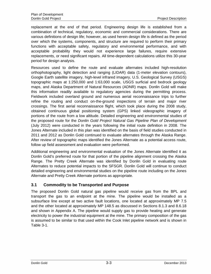
The design life of the proposed pipeline is 30 years. A 30-year design life does not indicate the pipeline and associated structure would be used up, failure-prone, or require
Plan of Development Donlin Gold Project Project Description
Donlin Gold 3-3 December 2013
replacement at the end of that period. Engineering design life is established from a combination of technical, regulatory, economic and commercial considerations. There are various definitions of design life; however, as used herein design life is defined as the period over which the systems, components, and structure are required to perform their primary functions with acceptable safety, regulatory and environmental performance, and with acceptable probability they would not experience large failures, require extensive replacements, or need significant repairs. All time-dependent calculations utilize this 30-year period for design analysis.
Resources used to define the route and evaluate alternates included high-resolution orthophotography, light detection and ranging (LIDAR) data (1-meter elevation contours), Google Earth satellite imagery, high-level infrared imagery, U.S. Geological Survey (USGS) topographic maps at 1:250,000 and 1:63,000 scale, USGS surficial and bedrock geology maps, and Alaska Department of Natural Resources (ADNR) maps. Donlin Gold will make this information readily available to regulatory agencies during the permitting process. Fieldwork included overland ground and numerous aerial reconnaissance trips to further refine the routing and conduct on-the-ground inspections of terrain and major river crossings. The first aerial reconnaissance flight, which took place during the 2008 study, obtained continuous global positioning system (GPS) linked videographic imagery of portions of the route from a low altitude. Detailed engineering and environmental studies of the proposed route for the Donlin Gold Project Natural Gas Pipeline Plan of Development (July 2012) were conducted in the years following the initial route definition in 2008. The Jones Alternate included in this plan was identified on the basis of field studies conducted in 2011 and 2012 as Donlin Gold continued to evaluate alternates through the Alaska Range. After review of topographic maps identified the Jones Alternate as a potential access route, follow up field assessment and evaluation were performed.
Additional engineering and environmental evaluation of the Jones Alternate identified it as Donlin Gold’s preferred route for that portion of the pipeline alignment crossing the Alaska Range. The Pretty Creek Alternate was identified by Donlin Gold in evaluating route Alternates to reduce potential impacts to the SFSGR. Donlin Gold will continue to conduct detailed engineering and environmental studies on the pipeline route including on the Jones Alternate and Pretty Creek Alternate portions as appropriate.
3.1 Commodity to be Transported and Purpose The proposed Donlin Gold natural gas pipeline would receive gas from the BPL and transport the gas to an endpoint at the mine. The pipeline would be installed as a subsurface line except at two active fault locations, one located at approximately MP 7.5 and the other located at approximately MP 148.5 as discussed in Sections 8.1.3 and 8.6.18 and shown in Appendix A. The pipeline would supply gas to provide heating and generate electricity to power the industrial equipment at the mine. The primary composition of the gas is assumed to be similar to that used within the Cook Inlet pipeline network and is shown in Table 3-1.

Plan of Development Donlin Gold Project Project Description
Donlin Gold 3-4 December 2013
Table 3-1: Composition of Gas to be Transported
Component Unit Typical Contractual Limit
Methane Mol% 98.851 TBD
Carbon dioxide Mol% 0.541 TBD
Nitrogen Mol% 0.539 TBD
Ethane Mol% 0.063 TBD
C4+ Mol% 0.006 TBD
C4+ = all hydrocarbons having more than four carbon atoms TBD = to be determined
Other characteristics of the gas are expected to be: • Specific gravity: 0.5618 • Typical water content: 2.5 to 3.5 lbs. per million standard cubic feet (mmscf) • Maximum water content: 4 lbs. per mmscf • Energy content: 1,000 British thermal units (Btu) per cubic foot
The quantity of natural gas that can be transported through the mainline is 73 mmscfd, with a MAOP of 1,480 psig. Refer to Section 8.5.3 and Table 8-16 for more information.
3.2 Pipe to be used for Transportation of Natural Gas The Donlin Gold natural gas pipeline requires the use of an estimated 319 miles (513 km) of pipe. Per 49 CFR 192, pipe of the appropriate minimum thickness would be used for pressure containment is based upon location class.
The pipeline would be installed in class 1 locations, with a corresponding design factor (design factors determine the maximum allowable operating stress in the pipeline) of 0.72 except as otherwise required as per 49 CFR 192.111. The Alternate MAOP requirements of 49 CFR 192.620, requiring the additional design requirements of 49 CFR 192.112, are not utilized in any section of this pipeline. A 14-inch (356 mm) diameter (outside diameter), API-5L X-52 PSL2 pipe, with a maximum allowable operating pressure of 1,480 psig would be used. The minimum required wall thickness for pressure containment of this pipe with a design factor of 0.72 is 0.28 inches. However, it was determined pipe with a wall thickness below 0.30 inch (7.62 mm) would be difficult to transport and handle without resulting in pipe damage (denting). The minimum, and baseline, pipe wall thickness (WT) selected for use on this pipeline is 0.312 inch (7.9 mm), which is a standard wall thickness of the American Petroleum Institute (API) Specification 5L. Geotechnical hazards that require pipe with greater wall thickness would be determined in the final design. Wall thicknesses greater than the minimum required for pressure containment (0.344-inch [8.7 mm], 0.375-inch [9.5 mm], or 0.406 [10.3 mm] WT) are specified in areas where these types of hazards require additional strength to maintain pipeline integrity. Other potential use of pipe with a WT in excess of the minimum required for pressure containment is for pipe requiring additional strength during pressure testing because of large elevation changes. Another design option is to use heavy wall pipe (0.375 inch [9.5 mm] WT) to maintain buoyancy control in wetlands, so other buoyancy control measures such as saddlebags or screw anchors would
Plan of Development Donlin Gold Project Project Description
Donlin Gold 3-5 December 2013
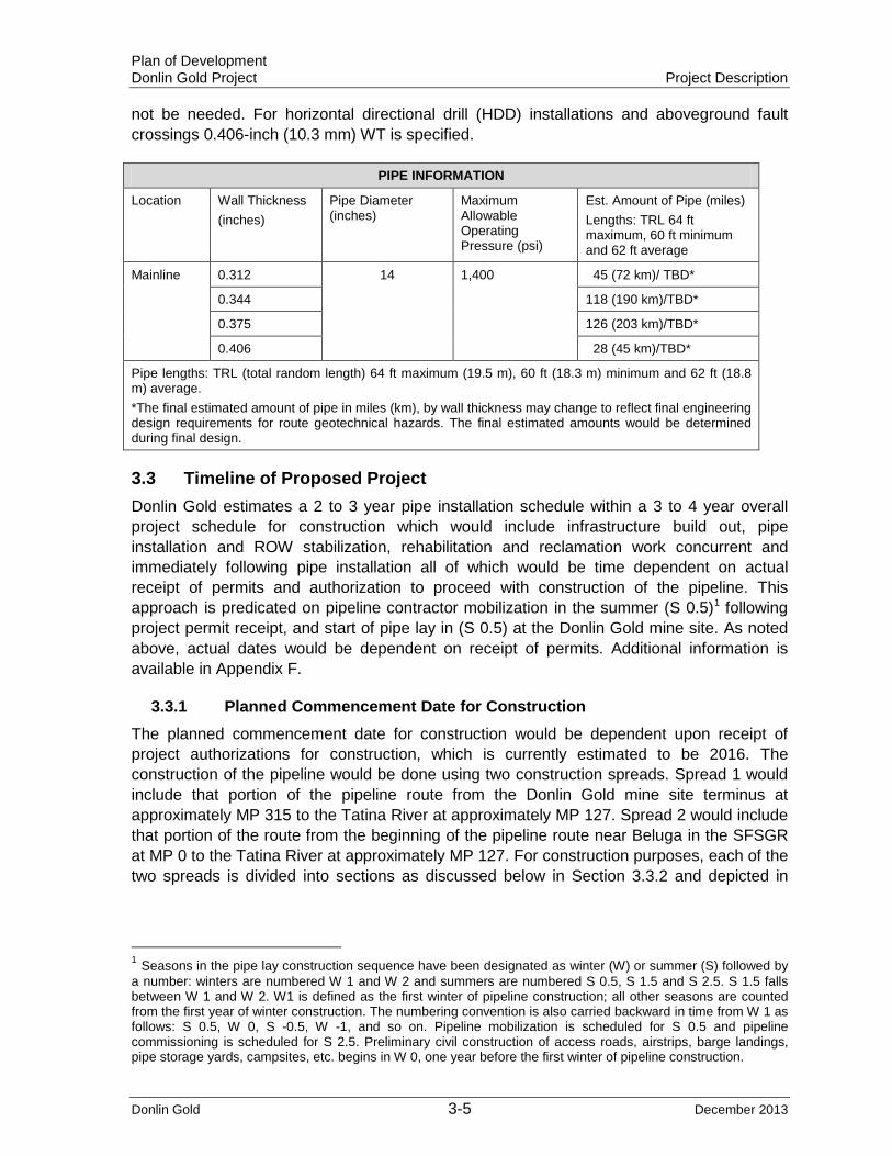
not be needed. For horizontal directional drill (HDD) installations and aboveground fault crossings 0.406-inch (10.3 mm) WT is specified.
PIPE INFORMATION
Location Wall Thickness (inches)
Pipe Diameter (inches)
Maximum Allowable Operating Pressure (psi)
Est. Amount of Pipe (miles) Lengths: TRL 64 ft maximum, 60 ft minimum and 62 ft average
Mainline 0.312 14 1,400 45 (72 km)/ TBD*
0.344 118 (190 km)/TBD*
0.375 126 (203 km)/TBD*
0.406 28 (45 km)/TBD*
Pipe lengths: TRL (total random length) 64 ft maximum (19.5 m), 60 ft (18.3 m) minimum and 62 ft (18.8 m) average. *The final estimated amount of pipe in miles (km), by wall thickness may change to reflect final engineering design requirements for route geotechnical hazards. The final estimated amounts would be determined during final design.
3.3 Timeline of Proposed Project Donlin Gold estimates a 2 to 3 year pipe installation schedule within a 3 to 4 year overall project schedule for construction which would include infrastructure build out, pipe installation and ROW stabilization, rehabilitation and reclamation work concurrent and immediately following pipe installation all of which would be time dependent on actual receipt of permits and authorization to proceed with construction of the pipeline. This approach is predicated on pipeline contractor mobilization in the summer (S 0.5)1 following project permit receipt, and start of pipe lay in (S 0.5) at the Donlin Gold mine site. As noted above, actual dates would be dependent on receipt of permits. Additional information is available in Appendix F.
3.3.1 Planned Commencement Date for Construction The planned commencement date for construction would be dependent upon receipt of project authorizations for construction, which is currently estimated to be 2016. The construction of the pipeline would be done using two construction spreads. Spread 1 would include that portion of the pipeline route from the Donlin Gold mine site terminus at approximately MP 315 to the Tatina River at approximately MP 127. Spread 2 would include that portion of the route from the beginning of the pipeline route near Beluga in the SFSGR at MP 0 to the Tatina River at approximately MP 127. For construction purposes, each of the two spreads is divided into sections as discussed below in Section 3.3.2 and depicted in
1 Seasons in the pipe lay construction sequence have been designated as winter (W) or summer (S) followed by a number: winters are numbered W 1 and W 2 and summers are numbered S 0.5, S 1.5 and S 2.5. S 1.5 falls between W 1 and W 2. W1 is defined as the first winter of pipeline construction; all other seasons are counted from the first year of winter construction. The numbering convention is also carried backward in time from W 1 as follows: S 0.5, W 0, S -0.5, W -1, and so on. Pipeline mobilization is scheduled for S 0.5 and pipeline commissioning is scheduled for S 2.5. Preliminary civil construction of access roads, airstrips, barge landings, pipe storage yards, campsites, etc. begins in W 0, one year before the first winter of pipeline construction.
Plan of Development Donlin Gold Project Project Description
Donlin Gold 3-6 December 2013
Table 3-2. Each section is scheduled for summer season or winter season construction which is designated as W for winter and S for summer.
Areas for summer or early fall construction were chosen by considering geotechnical and terrain-related issues. Sections with geotechnical conditions that allow a high proportion of grade-only ROW were identified for summer construction. Continuity of graded terrain was needed for a continuous construction section to minimize the need to move crew and equipment. Gravel workpads or mats could be used to link graded portions of the ROW that are separated by wetlands and/or thaw-unstable permafrost.
Geotechnical conditions that allow summer construction include the presence of thaw-stable permafrost and thawed ground with surface or near surface soils capable of supporting construction equipment, with thin surface overburden or organic layers. Gravel floodplains, weathered bedrock hills, landslide rubble, and gravel outwash fans are examples of soils suitable for summer construction. Intermittent and low-grade wetlands capable of supporting construction equipment on mats are included in the summer category.
Terrain is an important factor for summer construction. Steep hills pose a safety problem for wheeled construction equipment operated in the winter. This would be especially true on south-facing slopes in March, when solar radiation would make snow or ice pads mushy and slippery. Sand and gravel cannot be used for traction on ice pads late in the winter season because the dark traction material would hasten the loss of the ice pad through solar radiation gain.
In areas where there is a need to make extensive sidehill cuts to make a level ROW parallel to the trench bottom, this work would best be accomplished in summer. However, there are many sidehills in pipeline construction Sections 1 and 2 of Spread 2, and they are separated by marshes and wetlands, making summer access difficult or impractical. These sidehills would be allowed to maintain their snow cover to reduce frost penetration (the snow cover acts as an insulator), allowing easier excavation during winter construction. Specific locations and details regarding sidehill cuts would be provided during final design.
The selection of steep terrain for summer is preferred and was applied in pipeline construction Section 3B of Spread 2, and Sections 3C and 6 of Spread 1 but could not be applied in Sections 1 and 2 of Spread 2 because of the presence of intermittent marshes.
The areas selected for summer would not always be continuous in avoiding wetlands and must be linked by mats or gravel workpads installed over short areas.
The winter section determination includes all areas that cannot be constructed in summer: areas with thaw-unstable permafrost, thick organic topsoil layers, wetlands, bogs, and flat terrain. Areas with limited sidehills are preferred for winter construction. Snow and ice pads and frost packing ROW construction modes can be used for these conditions. Unless there is a nearby source of water, ice and snow pads would be very difficult to construct because of long haul distances. In such cases, winter gravel workpads can be constructed and can possibly be thinner than summer workpads. Winter gravel workpads may also be advisable for areas with steep longitudinal slopes or sidehill cross-slopes. The use of winter gravel workpads would be evaluated during final design.
Preliminary work including ROW clearing, shoofly (a road along the pipeline corridor built to bypass an obstacle such as a river, steep slope, etc.) and access road construction, early

Plan of Development Donlin Gold Project Project Description
Donlin Gold 3-7 December 2013
material site development, construction of pipe storage yards (PSYs), barge landings and camp pads, construction of airstrips and airstrip upgrades, camp mobilization, camp construction, and installation of construction communications would begin approximately one (1) year before the first winter of pipeline construction during the winter (W 0) before the summer of pipeline contractor mobilization (S 0.5).
Pipe haul to the PSYs would also begin approximately 1 year before the first winter of pipeline construction, except in pipeline construction Section 6 of Spread 1, where pipe hauling would be approximately one (1) year before the first summer of pipeline construction (S 0.5), just after the civil contractors have established access from the mine toward the George River and from the Kuskokwim River toward the George River. The pipe haul to the PSYs would be part of the pipeline contractors’ scope of work.
The pipeline construction contractors would be scheduled to mobilize in summer (S 0.5), based on receipt of project permits in the fall of W 0. The pipeline contractor for Spread 1 that mobilizes up the Kuskokwim River to the proposed Donlin Gold mine site would begin ROW grading immediately upon mobilization in late June (S 0.5) and proceed with all pipe installation activities. The Spread 1 civil contractor would mobilize in (S 0.5) and would begin infrastructure development and ROW clearing during that same summer, extending into the winter and spring of (W 0) if needed, including the following primary activities:
• Development of material sites • Bedding and padding production • Construction of access roads, material sites, barge landings, campsites, airstrips,
and ROW clearing including shoofly roads needed for pipe hauling • Construction of temporary construction access mats, bridges, and gravel workpad at
the three George River crossings
In the summer preceding any winter or summer pipeline construction, some preliminary civil work would be completed. Such work would include access road construction, gravel workpad construction (where possible), and production of bedding/padding material. These activities are best accomplished in summer.
3.3.2 Estimated Construction Time Donlin Gold estimates a 2 to 3 year pipeline installation schedule and 3 to 4 year overall project construction schedule, including infrastructure build out and initial ROW stabilization, rehabilitation and reclamation.
The proposed pipeline would be constructed using two pipeline construction spreads and generally working during two winters and two or three summer construction seasons:
• Pipeline construction would be divided into the two spreads, one approximately 188.60 miles (303.5 km) in length and one approximately 126.60 miles (203.7 km) in length.
Each spread would be awarded to a single pipeline contractor that would work over a period of 2 to 3 years to install the pipeline:
• Spread 1 (MP 315 to MP 126.6) would be further broken into four sections that would vary in length from 17.8 to 67.6 miles (28.65 to 108.79 km)

Plan of Development Donlin Gold Project Project Description
Donlin Gold 3-8 December 2013
• Spread 2 (MP 0 to MP 126.6) would be further broken into four sections that would vary in length from 9.8 to 51.0 miles (15.77 to 82.08 km)
Each section would be scheduled for installation during a single winter or summer season with start of ROW work and end of season dates estimated as shown in Tables 3-2 and 8-2.
Construction of access roads and gravel workpads, and production of bedding and padding material would be done primarily during the season that proceeds the pipeline construction season, whether winter or summer.
Pressure testing and final reclamation of winter sections would always take place during the spring shoulder season and/or the summer after pipe lay. Nevertheless stabilization, rehabilitation and reclamation including erosion and sedimentation control activities would progress to the extent feasible and prudent as construction progresses.
The construction season for any particular section is based on terrain, geotechnical conditions, most efficient ROW construction mode, season length, accessibility, and other factors.
3.3.3 Planned Commencement Date for Operation The planned date to commence operation of the natural gas pipeline to support the proposed Donlin Gold mine project is estimated to be in S 2.5, in approximately mid-2019 or later.
3.3.4 Duration of Pipeline Operation The pipeline is expected to be in operation for at least the productive life of the Donlin Gold proposed mine project. The anticipated mine life is 25 to 30 years. The engineering design life of the pipeline is 30 years. A 30-year design life does not indicate the pipeline and associated structure would be used up, failure-prone, or require replacement at the end of this period. Engineering design life is established from a combination of technical, regulatory, economic and commercial considerations. There are various definitions of design life; however, as used herein it is defined as the period over which the systems, components, and structure are required to perform their primary functions with acceptable safety, regulatory and environmental performance, and with acceptable probability they would not experience large failures, require extensive replacements, or need significant repairs. All time-dependent calculations utilize this 30-year period for design analysis.

Plan of Development Donlin Gold Project Project Description
Donlin Gold 3-9 December 2013
Table 3-2: Spread Execution Sequence
Section From
Milepost To
Milepost Length (Miles) Season*
Start for ROW Work
Start for Pipe Lay
Complete for Pipe Lay End-of-Season
Spread 1
6 315.2 247.6 67.6 S0.5 July- Donlin Mine
August October November-Alpine Ridge
5 247.6 196.6 51.0 W1 November-Alpine Ridge
January March April- Big River
3C 144.4 126.6 17.8 S1.5 May- South Fork
Kuskokwim River
July August September- Tatina River
4 144.4 196.6 52.2 W2 November- South Fork Kuskokwim
River
January March April- Big River
Subtotal Spread 1 188.6
Spread 2
1 0.0 50.5 50.8 W1 November- Beluga
January March April- Skwentna River
3A 101.8 111.6 9.8 W1 March- Puntilla Lake
March April April- Threemile Creek
3B 111.6 126.6 15.0 S1.5 June-Threemile
Creek
July August September- Tatina River
2 101.8 50.8 51.0 W2 November- Puntilla Lake
January March April- Skwentna River
Subtotal Spread 2 126.0
Total Route 315.2 ------------- (315 for narrative purposes in this PoD)
ROW = right of way *Seasons in the pipe lay construction sequence have been designated as winter (W) or summer (S), followed by a number: winters are numbered W 1 and W 2 and summers are numbered S 0.5, S 1.5 and S 2.5. S 1.5 falls between W1 and W2. W1 is defined as the first winter of pipeline construction; all other seasons are counted from the first year of winter construction. The numbering convention is also carried backward in time from W1 as follows: W 0, S -0.5, W -1, and so on. Pipeline mobilization is scheduled for S 0.5 and pipeline commissioning is scheduled for S 2.5. Preliminary Civil Construction of access roads, airstrips, barge landings, pipe storage yards, campsites, etc. begins in W 0, one year before the first winter of pipeline construction. Note: Daily pipe lay rate (in linear feet) and pipe lay duration (in number of days) for each construction section would be estimated during final design.
3.4 Estimated Employees
Table 3-3: Number of Persons Employed
Peak Construction Work Force 650 personnel
Operation and Maintenance Minimum of 4 full time personnel
Termination/Final Reclamation 50 personnel minimum (assuming that majority of pipeline would be abandoned in place)
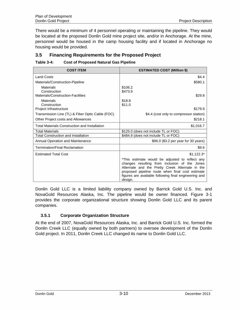
Plan of Development Donlin Gold Project Project Description
Donlin Gold 3-10 December 2013
There would be a minimum of 4 personnel operating or maintaining the pipeline. They would be located at the proposed Donlin Gold mine project site, and/or in Anchorage. At the mine, personnel would be housed in the camp housing facility and if located in Anchorage no housing would be provided.
3.5 Financing Requirements for the Proposed Project Table 3-4: Cost of Proposed Natural Gas Pipeline
COST ITEM ESTIMATED COST (Million $)
Land Costs Materials/Construction-Pipeline Materials Construction Materials/Construction-Facilities Materials Construction Project Infrastructure Transmission Line (TL) & Fiber Optic Cable (FOC) Other Project costs and Allowances
$4.4 $580.1
$106.2 $473.9
$29.8 $18.8 $11.0
$179.9 $4.4 (cost only to compressor station)
$218.1
Total Materials Construction and Installation $1,016.7 Total Materials $125.0 (does not include TL or FOC) Total Construction and Installation $484.9 (does not include TL or FOC) Annual Operation and Maintenance $96.0 ($3.2 per year for 30 years)
Termination/Final Reclamation $9.6
Estimated Total Cost $1,122.3* *This estimate would be adjusted to reflect any changes resulting from inclusion of the Jones Alternate and the Pretty Creek Alternate in the proposed pipeline route when final cost estimate figures are available following final engineering and design.
Donlin Gold LLC is a limited liability company owned by Barrick Gold U.S. Inc. and NovaGold Resources Alaska, Inc. The pipeline would be owner financed. Figure 3-1 provides the corporate organizational structure showing Donlin Gold LLC and its parent companies.
3.5.1 Corporate Organization Structure At the end of 2007, NovaGold Resources Alaska, Inc. and Barrick Gold U.S. Inc. formed the Donlin Creek LLC (equally owned by both partners) to oversee development of the Donlin Gold project. In 2011, Donlin Creek LLC changed its name to Donlin Gold LLC.

Plan of Development Donlin Gold Project Project Description
Donlin Gold 3-11 December 2013
Figure 3-1: Corporate Organization Structure
3.6 Natural Gas Transmission Line The proposed pipeline would be a gas transmission line connected to the existing gas pipeline transmission system approximately 7.7 miles (12.4 km) north of the Beluga Power Plant, near Beluga. The line would then be routed across the Alaska Range to a receipt point (outlet metering facility) at the proposed Donlin Gold mine site, a large volume customer. The proposed pipeline route is shown in Figure 1-1 and in Appendix A.
There are no plans at this time for future connections at intermediate points along the pipeline route. Any future connections to the pipeline whether for transporting or as off-takes of natural gas would be evaluated on a case-by-case basis. Factors that would be considered in determining the technical and economic feasibility of such cases may include as applicable, but are not limited to:
• Development and use of quality control measures to verify that any new product to be transported is compatible with the existing gas being transported
• Location and feasibility of any proposed connection • Compatibility with current use and operation

Plan of Development Donlin Gold Project Project Description
Donlin Gold 3-12 December 2013
• Impact to pipeline operations such as rate, pressure, estimated total quantity, continuity, and control of flow into and out of the pipeline
• Impact to Donlin Gold’s existing use and pipeline capacity • Leak detection monitoring and surveillance requirements • Measurement/custody transfer requirements • Compliance with applicable safety, environmental and relevant state and federal
pipeline regulations and laws including Regulatory Commission of Alaska (RCA) regulations
• Regulatory and state and federal Lease/ROW grant requirements • Any restrictions in ROW agreements with Calista, TKC, and Cook Inlet Region
Corporation (CIRI) • Economic feasibility of installing the new connection including compensation for
changes to operational costs • Recognition that the Donlin Gold natural gas pipeline is a transmission line
3.7 Surface and Subsurface Attributes The proposed pipeline would be buried except for short aboveground sections and aboveground pipeline appurtenances or ancillary equipment. The pipe and equipment would include the aboveground pipeline sections, each approximately 1,400 ft (427 m) in length where the pipeline crosses known active faults (at approximately MP 7.4 to MP 7.7 the Castle Mountain Fault and at approximately MP 148.4 to MP 148.7 the Denali-Farewell Fault), the metering stations at the tie-in point (MP 0) and the terminus (approximately MP 315), the pigging receiver and launcher near Farewell (approximately MP 156), the compressor station (approximately MP 0.4), and the ancillary aboveground piping and associated valves at the 16 remote MLV locations (aboveground block valves would be located at not greater than 20 mile (32 km) intervals along the line). If engineering requirements during final design determine that one or more segments of the pipeline situated in the Alaska Range require aboveground installation, these segments also will be aboveground. Appendix E provides engineering typicals for both buried and aboveground pipeline modes.
Burial modes would be trenches or HDD. Minimum depth of cover requirements for the pipeline in accordance with 49 CFR 192 are shown in Table 5-2 and Section 11.9.1. Fault crossings would be above grade with the pipe resting on lateral supports as shown in the engineering typicals in Appendix E.
As stated in Section 3.0 Donlin Gold is currently evaluating options for the origin of the fiber optic cable, whether from Beluga or elsewhere as discussed in Section 6.6. If the fiber optic communications cable originates in Beluga the proposed fiber optic cable may be carried on the power transmission supports for approximately 7.7 miles (12.4 km) to the metering module at the start of the pipeline, MP 0, then buried for approximately 0.4 miles (0.6 km) to the compressor station and then again buried for the remaining pipeline route to the mine, except at the two active fault crossings where the cable would be located above grade with the pipeline.

Plan of Development Donlin Gold Project Project Description
Donlin Gold 3-13 December 2013
3.8 Length/Width of ROW Area Needed for Related Activities Donlin Gold has identified a 300 ft (91 m) wide construction planning corridor on land along the proposed pipeline alignment. The construction planning corridor is located 150 ft (45.7 m) on each side of the centerline of the proposed pipeline route alignment. On state, federal, and CIRI lands Donlin Gold would apply for authorization within the 300 ft (91 m) construction planning corridor for a 100 ft wide (30.5 m) temporary construction ROW area and an additional adjoining 50 ft (15 m) permanent ROW as shown in Figure 8-1. Donlin Gold would then clear the required construction corridor within the authorized 150 ft (45.7 m) temporary construction ROW area 100 ft (30.5 m) plus permanent ROW 50 ft (15 m). A separate authorization would be applied for to install a fiber optic communications cable in the pipeline ROW.
The 300 ft (91 m) construction planning corridor would provide Donlin Gold with the flexibility to request variances where necessary within the construction planning corridor and to allow for adjustment to the pipeline alignment to minimize impacts in response to specific conditions which may be encountered during construction. In areas of challenging terrain or geotechnical and environmental conditions a wider or narrower use of clearing area may be required. Additional temporary workspace areas determined during final design that are outside the 150 ft (45.7 m) pipeline construction area but within the 300 ft (91 m) construction planning corridor needed at water body crossings and other challenging terrain locations required for safe pipeline construction or materials staging would be requested. Additional workspace may be restricted at sensitive environmental or cultural areas. Temporary access roads would be 24 ft (7 m) wide or narrower, where needed.
The width of the proposed permanent ROW for long-term O&M of the pipeline would be 50 ft (15 m) on state, Calista and CIRI lands and approximately 51 ft 2 inches (15.6 m) on Bureau of Land Management (BLM) managed land (50 ft (15 m) plus the diameter of the pipe). The ROW would be increased to accommodate the compressor station and any other permanent ancillary facility needs. The actual permanent ROW area and final pipeline alignment would be determined based on the final as-built survey. Section 4.4, Table 4-1 and Appendices A and B provide additional information related to the disturbance areas.
3.9 Ancillary to an Existing Right-of-Way The proposed pipeline would originate from the BPL and would not cross or parallel any existing pipeline, power line, or other utility throughout its route to the Donlin Gold mine site tie-in. The proposed pipeline would not cross any existing maintained public roads or railroads, with the exception of Pretty Creek Road in the SFSGR. Donlin Gold recognizes that there are existing trails or issued easements and ROWs, including RS-2477 routes and Section Line Easements (SLE’s) that may be affected by the proposed pipeline project. Land status information, including the location of existing rights-of-way and easements, excluding section line easements, is shown in Appendix A.
3.10 Route Description and Alternate Routes Considered
3.10.1 Pipeline The pipeline route, approximately 315 miles (507 km) in length, has been located and evaluated based on currently known technical, environmental, cultural, and economic considerations. Another consideration was minimization of private land that would be
Plan of Development Donlin Gold Project Project Description
Donlin Gold 3-14 December 2013
crossed. The criteria discussed in this section address these considerations. The actual design and engineering of the pipeline would take into consideration the environmental conditions determined to affect or potentially affect the pipeline, including unstable soils. This would be done in final design. Resources used to define the route and potential Alternates included high-resolution orthophotography, LIDAR data (1-meter elevation contours), historical high-level infrared imagery, USGS topographic maps at 1:250,000 and 1:63,000 scale, USGS surficial and bedrock geology maps. Fieldwork included overland ground and numerous aerial reconnaissance trips to further refine the routing and to conduct on-the-ground inspections of terrain and major river crossings. The first aerial reconnaissance flight, which took place during the 2008 pre-feasibility study, obtained continuous videographic imagery of the route from a low altitude. Comprehensive field surveys, geotechnical sampling, and hydrological and environmental studies were conducted in 2010 to assist in fine-tuning the route.
During summer 2010, three two-person crews were in the field to validate the desktop routing that had been completed in early 2010. Each crew included a construction superintendent and another person with a survey background. The crews were equipped with a mobile mapping device with an integral GPS that provided sub-meter accuracy. The crews were tasked with walking the alignment and verifying the selected alignment was constructible. If there was an opportunity to move the alignment slightly to better facilitate construction, the crew made and documented the alignment change. Proposed alignment changes were reviewed by pipeline engineering and geotechnical team members on a daily basis during field activities. Accepted changes were documented in the geographical information system (GIS) database and field geotechnical drilling crews were directed to new sampling locations.
The crews also verified the proposed, cleared ROW would be suitable to facilitate the movement of pipeline construction supplies, because there would be no permanent access road along the full length of the pipeline alignment. In areas identified having in excess of 12% longitudinal slope, shoofly access road routes were evaluated and documented by the field crews to better facilitate travel along the ROW.
As noted in Section 3.0, the Jones Alternate was identified on the basis of field studies conducted in 2011 and 2012 as Donlin Gold continued to evaluate potential Alternate alignments through the Alaska Range. Review of topographic maps identified the Jones Alternate as a potential access route which was then followed up by field assessment and evaluation.
The additional field assessment and evaluation of the Jones Alternate confirmed it as Donlin Gold’s preferred route for that portion of the pipeline alignment crossing the Alaska Range. Donlin Gold will continue to conduct detailed engineering and environmental studies on the Jones Alternate segment of the purposed pipeline route as needed.
Selection of the most technically suitable and constructible route involved the optimization of a number of considerations.
The following general criteria were used in this routing process:
• Minimization of total pipeline length • Minimization of the number of water and wetlands crossings • Avoidance of geotechnical hazards

Plan of Development Donlin Gold Project Project Description
Donlin Gold 3-15 December 2013
• Avoidance of hydrological hazards • Avoidance of known areas of environmental and cultural concern, including known
wetlands and cultural resource sites • Avoidance of areas with potential land use conflicts • Optimization of seasonal construction schedules • Minimization of construction in areas with steep slopes, permafrost terrain, marshes
and bogs, river crossings, and difficult access, and in other areas where construction would be challenging
• Minimization of visual impacts including minimum required maintenance clearing on permanent ROW where appropriate
3.10.2 Proposed Pipeline Route Description
Donlin Gold’s proposed natural gas pipeline route includes the Pretty Creek Alternate at the beginning of the pipeline route near Beluga and the Jones Alternate as the proposed route through the Alaska Range. Starting at MP 0 where the pipeline route begins at a tie-in with the existing Beluga Pipeline, the pipeline route traverses north through the SFSGR for approximately 5 miles (8 km) following the existing 100 ft (30 m) wide Pretty Creek Road easement (sometimes also referred to as Theodore Road) that has been improved as an all-season gravel road. The portion of the route in the SFSGR crosses previously disturbed lowland forest and skirts the edges of bogs and other wetlands. The route crosses two stream crossings, the Theodore River north of SFSGR at approximately MP 5.5 and the western fork of the Lewis River at approximately MP 7. The compressor station would be located inside the refuge at approximately MP 0.4.
From MP 0 to MP 101.8 the terrain is mixed rolling, mountainous, and flat terrain, with many areas of wetlands including hilly sections that contain perched marshes.
From Puntilla Lake at approximately MP 101.8 to Threemile Creek at approximately MP 111.6, the route runs through terrain that is mostly flat or gently sloped tundra over permafrost. The route crosses the Happy River at approximately MP 108.5 then proceeds along a low moraine ridge before turning north into the broad valley of Threemile Creek. For the 4 mile (6.4 km) interval ascending Threemile Creek Valley, the alignment was routed along its west limit and over low moraines and relic alluvial fans, thus avoiding the active floodplain and wetlands along the valley bottom.
At approximately MP 114.5 the alignment trends westerly as it approaches the unnamed pass that is the Alaska Range divide. This pass has an elevation of 3,870 ft (1,179.6 m). The short steep drainages immediately on each side of the pass are in narrow valleys with talus lobes and stabilized rock glaciers at the base of steep rock slopes. Here the route utilizes benches above the creeks that flow from the pass. At approximately MP 120.5 the route enters a typical broad “U shaped” valley characteristic of the glacial valleys in this region. As the route descends this valley it is typically on the benches or terraces with moderate to little slope that border this unnamed tributary of the Tatina River.
At approximately MP 127.3 the route crosses the Tatina River’s glacial braided floodplain at a natural constriction created by bedrock outcrops on both banks of the River. From the Tatina River the route immediately ascends to a broad open 2,800 ft (853.4 m) pass before entering into the Jones River valley.

Plan of Development Donlin Gold Project Project Description
Donlin Gold 3-16 December 2013
At approximately MP 130.5 the realignment begins the descent of the expansive Jones River Valley which is a typical relic glacial valley with an over broad glacial braided floodplain bordered by expansive relic alluvial fans and glacial drift terraces. The route is typically on the west side of the valley and makes use of the terraces above the valley bottom or is located on the high ground between the active river floodplain and the base of the steep mountain slopes which define this valley. The route from approximately MP 130.5 to MP 143 is within the Jones River Valley and roughly parallels the river. There would be two crossings of the Jones River at approximately MP 136.6 and MP 137.6. These crossings are necessary to avoid a section along the west side of the valley where the steep mountain slope descends directly to the river. Several tributaries of the Jones River are crossed on typically broad and relatively steep alluvial fans. Short intervals of the route are in the expansive Jones River flood plain. Ground conditions along the Jones River are typically excellent for pipeline construction and are conducive to summer season construction.
The route exits the mountains of the Alaska Range at approximately MP 143. At this point the route turns to the west and crosses the South Fork of the Kuskokwim River at approximately MP 146.5. At approximately MP 146.8 the pipeline crosses the Iditarod National Historic Trail (INHT), which is located seasonally on the ice of the South Fork of the Kuskokwim River. At approximately MP 147.4 the pipeline also crosses RST 174, the Rainy Pass-Big River RS 2477 ROW, which is co-located with the INHT. At approximately MP 148.3, the pipeline crosses the State Public Access Easement for the Rohn to Takotna section of the INHT (ADL 230363).
West of the South Fork of the Kuskokwim River the route traverses stabile glacial moraine and ancient glacial outwash flat as it passes between Egypt Mountain and Farewell Mountain.
The Denali Farewell Fault is crossed by the proposed route in the area from approximately MP 148.4 to MP 148.7. The fault crossing is in an area where the fault surface expression is readily apparent and subsurface conditions are amenable to an aboveground crossing design.
From MP 144.4 to MP 196.6 (Section 4 of Spread 1), the terrain is flat to rolling, with some kettle and karne terrain and is transected by north-flowing streams and rivers with some high and steep banks and broad, braided floodplains. Notable river crossing locations would include Sheep Creek at approximately MP 156.3, Windy Fork at approximately MP 168, Khuchaynik Creek at approximately MP 170.6, two unnamed rivers at approximately MP 174.5 and MP 176.6, the Middle Fork of the Kuskokwim River at approximately MP 182.7, and Big River at approximately MP 191.
From MP 196.6 to MP 247.6 the route runs through terrain that is variable and includes low-grade bedrock hills transected by low wetlands, three sizable rivers including the Kuskokwim River approximately at MP 240, the Tatlawiksuk River at approximately MP 216, and an unnamed tributary of the Tatlawiksuk River at approximately MP 205. This section of the route transitions into discontinuous permafrost, kettle and karne terrain for the 20 miles (32 km) closest to Big River.
From approximately MP 247.6 to MP 315 the route crosses terrain that is hilly to mountainous and follows the ridgelines with some steep knobs and valleys that would require shoofly road construction for movement of pipe and personnel. More detailed

Plan of Development Donlin Gold Project Project Description
Donlin Gold 3-17 December 2013
information regarding the route alignment is provided in the appendices attached to this PoD.
Alternate Pipeline Routes Considered Route segment alternates were evaluated at Beluga Mountain, Little Mt. Susitna, Round Mountain, Goodman Pass, Egypt Mountain, St. Johns Hill, Windy Fork, Big River, Tatlawiksuk River, Kuskokwim River, Moose Creek, and in the area of the Kuskokwim Hills, Rainy Pass, Jones, East Theodore, Beluga, and Pretty Creek. Alternates were also evaluated for the electric transmission line location.
Although many adjustments were made, these larger segment alternatives are discussed below and/or included in Figures 3-2 through 3-16.
3.10.3 Beluga Mountain Alternates The Beluga Mountain upper and lower alternate routes (Figure 3-2) were evaluated and the upper alternate route selected as it allowed the pipeline route to be moved to dryer slope areas from the low lying flatter areas to reduce stream crossings and wetland disturbance.
3.10.4 Little Mt. Susitna Alternates The Little Mt. Susitna Alternates (Figure 3-3) were evaluated and upper route selected as it relocated to the pipeline route from lower wetland areas with more fish bearing stream crossings to more of an upland route with improved constructability.
3.10.5 Round Mountain Alternates The Round Mountain east and west alternate routes (Figure 3-4) were evaluated and the west route was selected. The east route traverses the northeast side of Round Mountain along the Happy River valley. This route would have connected the selected route between approximately MP 97 and MP 101.2, south of Puntilla Lake. This route was not considered because of the presence of unstable, ice-rich soils along steep sideslope terrain, which was identified in the 2010 geotechnical program.
3.10.6 Goodman Pass Alternates The Goodman Pass Alternates (Figure 3-5) represent a crossing of the Alaska Range and were considered in the selection of the route proposed in the July 2012 PoD. This route would begin to the south of Rainy Pass and connect back to the route just north of Rohn. This alternate route was carefully reviewed, and the result of the analysis was documented in detail in a separate report (CH2M Hill 2010). The Goodman Pass Alternate was not selected for several reasons, including that the Clean Water Act (CWA) requires that if there is more than one alternative to an action, the alternative that has the least impacts to waters of the United States (U.S.), including wetlands, be selected unless there are compelling reasons, such as significant environmental issues associated with the selected alternative. The Goodman Pass route has 22% more impacts to waters of the U.S. than the Rainy Pass Alternate had, thus the Rainy Pass Alternate was selected at the time over the Goodman Pass Route. Some additional considerations that led to the selection of the Rainy Pass Alternate over the Goodman Pass Alternate included:
• Length approximately 6 miles (10 km) greater than the Rainy Pass Alternate • Construction issues related to very steep terrain through a constrained, narrow valley

Plan of Development Donlin Gold Project Project Description
Donlin Gold 3-18 December 2013
• Pipeline installation in the bottom of an active stream channel • Pipeline installation across geotechnical hazards (thaw-unstable, ice-rich side slopes
with slumping soils) • Paralleling the South Fork of the Kuskokwim River through the active, meandering
channel floodplain
Further evaluation of the Rainy Pass Alternate and the Jones Alternate is discussed in Sections 3.10.14 and 3.10.15. The Jones Alternate location is shown in Figure 3-5 in comparison to the location of Goodman Pass Alternates as the Jones Alternate was evaluated and selected over the Rainy Pass Alternate as the preferred route through the Alaska Range.
3.10.7 Egypt Mountain Alternate The Egypt Mountain Alternate (Figure 3-6) was evaluated and selected as part of the Rainy Pass Alternate for the alignment proposed in the July 2012 PoD prior to the identification, evaluation and selection of the Jones Alternate over the Rainy Pass Alternate. The Egypt Mountain Alternate allowed the route alignment to move to a higher area which would be dryer with less permafrost and wetlands. It allows the pipeline route to pass through a small valley through the mountains rather than wetter lowlands drainage areas.
3.10.8 St. John’s Hill Alternate The St. John’s Hill Alternate (Figure 3-7) was evaluated and selected as it allowed the pipeline route to be moved upslope closer to the mountains, on dryer terrain with less permafrost and wetlands. The route also allowed for smaller creek crossings.
3.10.9 Windy Fork Alternate The Windy Fork Alternate (Figure 3-8) was evaluated and southern route was selected as it provided improved approaches to the river crossing and reduced the amount of earthwork required to complete installation of the pipeline and associated access roads. This route also shortened the alignment and generally moved it so that the route requires a smaller cut coming out of the river valley and moved the pipeline alignment upslope into dryer areas with less wetlands and permafrost.
3.10.10 Big River Alternate The Big River Alternate (Figure 3-9) was evaluated and selected as it provided an easier exit that requires a smaller cut coming out of the river valley and moved the pipeline alignment upslope into dryer areas with less wetlands, permafrost, and smaller stream crossings.
3.10.11 Tatlawiksuk River Alternates The Tatlawiksuk River north and south alternate routes (Figure 3-10) were evaluated and the north route was selected as it allowed the pipeline to be routed through an area with more suitable ground conditions.
3.10.12 Kuskokwim River Alternates The Kuskokwim River north and south alternate routes (Figure 3-11) were evaluated and the north route was selected as it provided better access to upland areas and straightened the

Plan of Development Donlin Gold Project Project Description
Donlin Gold 3-19 December 2013
pipeline alignment. This alternate route also reduced the number of stream crossings necessary for construction purposes.
3.10.13 Moose Creek Alternates The Moose Creek short and long alternate routes (Figure 3-12) were evaluated and the short route was selected as it allows for straightening the pipeline alignment and reduced the overall route distance while staying in the upland area. Additionally this alternate route improved access for equipment and would reduce the amount of construction activity.
3.10.14 Kuskokwim Hills Alternates A more southern route was proposed in 2008 between the Kuskokwim River and the mine terminus (Figure 3-13). During the 2010 summer field season, a more northern route through this area which reduces the length of the proposed pipeline by approximately 5 miles (8 km) and avoids potential land use conflicts on private lands was identified. The northern route was selected because areas along the southern route are considered to be more difficult from a constructability perspective the pipeline than along the more northern route, because of low lying areas and additional wetland impacts.
3.10.15 Rainy Pass Alternate As shown in Figure 3-14 the Rainy Pass Alternate proceeds in a more northerly direction past Puntilla Lake as the topography becomes more subdued, with many flat areas and low, broad ridges. This gently rolling topography continues to the entrance of Rainy Pass. The route was shifted approximately 0.25 mile (.4 km) to co-locate an airstrip with the route, effectively minimizing surface area impacts. Fisheries studies at the second crossing of the Happy River found this area to be a significant salmon spawning habitat; consequently, an HDD crossing was proposed. The route through Rainy Pass starts at an elevation of 2,500 ft (762 m) and gradually climbs to a maximum elevation of 3,327 ft (1,014 m) over a distance of approximately 6 miles (9.6 km). Over the next 10 miles, the route drops to an elevation of 1,500 ft (457 m) at the Tatina River crossing. The adjacent valley slopes are steep, and streams are deeply incised along several sections of the route through the pass and along Dalzell Creek. The route through the pass was optimized to avoid steep sidehills and reduce the number of stream crossings of Pass Creek and Dalzell Creek. At Dalzell Gorge, the terrain is steep, and several potentially active slope movement areas were verified, making this a challenging location in which to construct a ROW and an HDD crossing under these geotechnical hazards as planned.
The route was also shifted from the south side of the Tatina Valley to the north side of the valley to avoid areas of potential slope instability. The alluvial floodplain of the Tatina River is approximately 0.35 mile (0.56 km) wide at its confluence with Dalzell Creek. Moderate to steep side slopes exist on the north side of the river for more than 3 miles (4.8 km), and geotechnical probing indicated permafrost soils along most of this section. Beyond these slopes, the route traverses the floodplain of the river for nearly 2 miles (3 km). Scour depth calculations for this river crossing showed potential of approximately 4 ft (1.2 m) of scour below the thalweg of the river, which could equate to 9 ft (2.7 m) with 11 ft (3.3 m) of trench depth in the river and across the identified flood plain. Groundwater levels detected at or near surface would result in wet trench, making conventional cut-and-fill construction through the floodplain difficult.

Plan of Development Donlin Gold Project Project Description
Donlin Gold 3-20 December 2013
Beyond the South Fork of the Kuskokwim River crossing, the route follows the lower western slopes of the South Fork of the Kuskokwim River valley in rolling to hilly terrain with some moderate side slopes at an approximate elevation of 1,300 ft (396 m). The route crosses a 1.4-mile (2.25 km), flat alluvial plain at the Post River and continues northward through rolling hills with scattered lakes and boggy areas. Several minor route adjustments were made to optimize stream crossing profiles and reduce grades along the route. In the Tin Creek area the route was adjusted to the south and west to avoid extremely steep slopes bounding a small alluvial valley. The route provides better access along the route and traverses hilly terrain, rising approximately 700 ft (213 m) to more than 2,000 ft (609 m) in elevation.
The route crosses the Denali Fault trace, exits the hilly terrain onto flat and gently rolling plains in the area of MP 152, then turns to the southwest.
The Rainy Pass Alternate has potential land use and existing trails conflicts. On portions of the State land crossed by the Rainy Pass Alternate there is a 400-ft (122 m) wide ROW for the INHT and a 400 ft (122 m) wide State Public Access Easement for the Iditarod Race Trail.
After identification and evaluation of the Jones Alternate (approximately MP 106 to MP 152) the pipeline was realigned to the Jones Alternate as Donlin Gold’s proposed route through the Alaska Range.
3.10.16 Jones Alternate The Jones Alternate traverses mostly vacant State land, with the exception of CIRI-owned sections where the route re-joins the main pipeline route. The Jones Alternate also avoids much of the potential conflict with the INHT that existed with the Rainy Pass Alternate.
The Jones Alternate deviates from the Rainy Pass Alternate at approximately pipeline MP 106. From this point the Jones Alternate trends northwest to a crossing of the Happy River at approximately MP 108.5. This crossing of the Happy River was selected to allow for an “open cut” type crossing of the river. This crossing has been specifically sited to avoid preferred salmon spawning habitat. From the Happy River crossing, the route proceeds along a low moraine ridge before turning north into the broad valley of Threemile Creek. For the 4 mile (6.4 km) interval ascending Threemile Creek Valley, the route was located along its west limit and over low moraines and relic alluvial fans, thus avoiding the active floodplain and wetlands along the valley bottom.
At approximately MP 114.5 the route trends westerly as it approaches an unnamed pass that is the Alaska Range divide. This pass has an elevation of 3,870 ft (1,179.6 m). The short steep drainages immediately on each side of the pass are in narrow valleys with talus lobes and stabilized rock glaciers at the base of steep rock slopes. Here the Jones Alternate utilizes benches above the creeks that flow from the pass. A temporary construction pad typical of those used in steep mountainous terrain would be developed the length of the pipeline corridor, thus permitting continuity of access for the full length of the Jones Alternate. At approximately MP 120.5 the route enters a typical broad “U shaped” valley characteristic of the glacial valleys in this region. As the alignment descends this valley it is typically on the benches or terraces with moderate to little slope that border an unnamed tributary of the Tatina River.

Plan of Development Donlin Gold Project Project Description
Donlin Gold 3-21 December 2013
At approximately MP 127.3 the route crosses the Tatina River’s glacial braided floodplain at a natural constriction created by bedrock outcrops on both banks of the river. Elevation at the crossing is 1,800 ft (548.6 m). A 500 ft (152.4 m) long open cut type crossing would be used since the river flow is relatively minor and conditions at the crossing are very favorable. From the Tatina River the route immediately ascends to a broad open 2,800 ft (853.4 m) pass before entering into the Jones River valley.
At approximately MP 130.5 the route begins the descent of the expansive Jones River Valley which is a typical relic glacial valley with an over broad glacial braided floodplain bordered by expansive relic alluvial fans and glacial drift terraces. The Jones Alternate is typically on the west side of the valley and makes use of the terraces above the valley bottom or is located on the high ground between the active river floodplain and the base of the steep mountain slopes which define this valley. The route from approximately MP 130.5 to MP 143 is within the Jones River Valley and roughly parallels the river. There would be two crossings of the Jones River at approximately MP 136.6 and MP 137.6. These crossings are necessary to avoid a section along the west side of the valley where the steep mountain slope descends directly to the river. Crossing of the river would be by open cut methods as appropriate for the character of the river crossing sites. Several tributaries of the Jones River are crossed on typically broad and relatively steep alluvial fans. Short intervals of the route are in the expansive Jones River flood plain. The Jones River is unique in that except for high rainfall events the river does not actively flow. This has been observed to be the case for most years beyond approximately MP 136.6. Ground conditions along the Jones River are typically excellent for pipeline construction and are conducive to summer season construction. As opposed to the Rainy Pass Alternate, far fewer issues with permafrost or potential geotechnical hazards have been identified along the Jones Alternate.
The Jones Alternate exits the mountains of the Alaska Range at approximately MP 143. At this point the route turns to the west and crosses the South Fork of the Kuskokwim River at approximately MP 146.5. The crossing of the potentially active floodplain of the South Fork of the Kuskokwim River extends for over 2 miles (3.2 km). Scour depth calculations for this river crossing indicate potential of approximately 4 ft (1.2 m) of scour below the thalweg of the river, which could equate to 9 ft (2.7 m) with 11 ft (3.4 m) of trench depth in the river and across the identified flood plain. It is anticipated that the open cut crossing of the South Fork of the Kuskokwim River would be completed during a period of low river flow in the early or late winter season.
At approximately MP 146.8 the pipeline route crosses the INHT, which is located seasonally on the ice of the South Fork of the Kuskokwim River. At approximately MP 147.4 the pipeline route also crosses RST 174, the Rainy Pass-Big River RS 2477 ROW, which is co-located with the INHT. At approximately MP 148.3, the pipeline crosses the State Public Access Easement for the Rohn to Takotna section of the INHT (ADL 230363).
West of the South Fork of the Kuskokwim River the Jones Alternate traverses stable glacial moraine and ancient glacial outwash flat as it passes between Egypt Mountain and Farewell Mountain. The Jones Alternate extends to approximately MP 152.
The Denali Farewell Fault is crossed by the Jones Alternate from approximately MP 148.4 to MP 148.7. The route fault crossing is in an area where the fault surface expression is readily apparent and subsurface conditions are amenable to an aboveground crossing design.

Plan of Development Donlin Gold Project Project Description
Donlin Gold 3-22 December 2013
Construction material sources and suitable locations for construction infrastructure sites are readily available along the Jones Alternate due to typically favorable terrain and soil characteristics.
The Jones Alternate is approximately the same length as the Rainy Pass Alternate as shown in Figure 3-14 and crosses lands that are either patented or tentatively approved to patent to the State of Alaska with the lone exception of several sections of land that are interim conveyed to CIRI. CIRI lands are shown in Appendix A in SM, T28N, R24W, and Sections 22, 23, 24, 26 and 27. After environmental and engineering evaluations, the Jones Alternate was selected over the Rainy Pass Alternate and is shown in Figure 3-15.
3.10.17 East Theodore Alternate Donlin Gold compared the proposed Pretty Creek Alternate with the East Theodore Alternate and the Beluga Alternate, which included both the pipeline routes and compressor station locations. The East Theodore Alternate (proposed in the July 2012 PoD) route would begin at a connection with the existing 20 inch (508 mm) gas pipeline in the SFSGR and run north through the SFSGR for approximately 4.8 miles (7.7 km) paralleling the Theodore River Valley roughly a half mile east of the river (Figure 3-16). The route length from the existing BPL tie-in point to the common point of reference shown in Figure 3-16 would have been approximately 5.5 miles (8.9 km). The East Theodore Alternate would have resulted in a 100 ft (30 m) cleared ROW through undisturbed forest habitat.
The East Theodore Alternate would have required upgrading the Theodore River Bridge on the Beluga Highway to safely accommodate heavy equipment traffic. The East Theodore Alternate also would have crossed the far western fork of the Lewis River.
Two compressor station locations were considered for the East Theodore Alternate; at or near MP 0, the tie-in with the existing BPL, or at MP 5 immediately north of the SFSGR boundary. The compressor station at MP 5 would have been a roadless alternative, construction would have been during the winter, and access during operations would have been via helicopter. A 0.25 acre (0.10 ha) helipad and a construction camp also would have been required. Following evaluation of the alternate routes the Pretty Creek Alternate was selected and the pipeline route realigned to the Pretty Creek Alternate.
3.10.18 Beluga Alternate The Beluga Alternate was considered and would have avoided the SFSGR altogether by skirting along the western edge of the refuge as shown in Figure 3-16. The Beluga Alternate would have been 12.6 miles (20.3 km) from a BPL tie-in to the common point of reference and the longest route with the largest disturbance of unmanaged lowland forest. The Beluga Alternate would have required eight stream crossings: three branches of the Beluga River, three forks of Pretty Creek, the Theodore River, and the far western fork of the Lewis River.
The compressor station for the Beluga Alternate would have been located at or near the tie-in with the existing BPL. Following evaluation of the Beluga Alternate the Pretty Creek Alternate was selected.
3.10.19 Pretty Creek Alternate The Pretty Creek Alternate was selected as Donlin Gold’s proposed route through the SFSGR at the beginning of the Donlin Gold gas pipeline. The Pretty Creek route would
Plan of Development Donlin Gold Project Project Description
Donlin Gold 3-23 December 2013
begin at a tie-in with the existing BPL in the SFSGR and run north through the refuge following the existing 100 ft (30 m) wide Pretty Creek Road easement (sometimes also referred to as Theodore Road) that has been improved with an all-season gravel road shown in Figure 3-16. Approximately 50 ft (15.2 m) of the ROW width has already been cleared to accommodate the road. The remaining forest and shrubland within the proposed pipeline ROW needed for construction would be cleared. The Pretty Creek Alternate would cross approximately 5.1 miles (8.2 km) of SFSGR. Most of the Pretty Creek Alternate crosses previously disturbed lowland forest and skirts the edges of bogs and other wetlands.
The Pretty Creek Alternate would require two stream crossings, the Theodore River north of SFSGR and the western fork of the Lewis River.
3.10.20 Alternate Routes Assessment for the Electric Transmission Line Three alternate routes were reviewed for locating the aerial power transmission line from the Beluga Power Plant to the pipeline compressor station for the July 2012 PoD, where the compressor station was located at MP 5 for the East Theodore Alternate alignment. The first transmission line alternate route was a nearly direct line between the Beluga Power Plant and the compressor station at MP 5. The second alternate route does not require routing the power transmission line within the SFSGR. The third alternate route essentially paralleled the existing Chugach Electric Association (CEA) high-voltage transmission lines until it reached the point near the proposed Donlin Gold East Theodore Alternate pipeline tie-in to the BPL and then followed the pipeline ROW to the proposed gas compressor station at MP 5.
The third alternate route was selected to accommodate the East Theodore Alternate because there was a need for power and communications at the BPL tie-in at MP 0 for the metering station as well as to the compressor station at MP 5. This route from the Beluga Power Plant to the metering station reduced the distance and amount of clearing for the new transmission line and fiber optic cable that would be required inside the SFSGR by paralleling the existing electric transmission lines and gas line corridors to MP 0. From MP 0 to MP 5 the power line would follow the pipeline corridor and the fiber optic cable could be buried in the pipeline ROW
The Pretty Creek Alternate would continue to use option three for the aerial electric transmission line to the beginning of the Pretty Creek Alternate at MP 0. From the BPL tie-in at MP 0 the aerial power transmission line would run the short distance of approximately 0.4 miles (.6 km) to the compressor station at approximately MP 0.4 of the Pretty Creek Alternate. This reduces both the length of the aerial power transmission line from the Beluga Power Plant to the metering station at MP 0 as well as the distance to the compressor station at approximately MP 0.4 as compared to the East Theodore Alternate where the compressor station was located at MP 5. Refer to Figures 3-16, 6-1, 8-4 and Appendix A for additional information.

ROUTE SELECTED
234561234561234561234
11109871211109871211109871211109
141516171813141516171813141516171813141516
232221201924232221201924232221201924232221
2627282930252627282930252628293025262728
353433323136353433323136353433323136353433
23456123456234561234
11109871211109871211109871211109
1415161718131415161813141516171813141516
2322212019242322212019242322212019242221
2627282930252628293025262728293025262728
3534333231363433323136353433323136353433
2345612456123456124
11109871211109871211109871211109
T21N R12W
T18N R9WT18NR10W
T18NR12W
T20N R9W
T20NR11W
T19NR10W
T18NR11W
T20NR10W
T21N R11W
T20NR12W
T19NR12W
T19NR11W
T19N R9W
MP-45
MP-48
MP-44
MP-42
MP-41
MP-40
MP-39
MP-38
MP-47
MP-37
MP-36
MP-35
MP-34
MP-33
MP-32
MP-31
MP-46
Copyright:© 2013 National Geographic Society, i-cubed
BELUGA MOUNTAIN ALTERNATES0 1.5 30.75 km
FIGURE:SCALE:
DG: ENG0140.mxd, 12/10/13, R06
0 1 20.5 mi
DONLIN GOLD PROJECT
3-2
Milepost
Proposed Natural Gas Pipeline Alignment
Beluga Mountain Alternate (Upper)
Beluga Mountain Alternate (Lower)Seward Meridian, UTM Zone 5, NAD83

Yentna River
ROUTE SELECTED
ALEXANDERCREEK
REC RIVER
TALACHULITNAREC RIVER
SUSITNAFLATS SGR
MP-22
MP-23
MP-24
MP-25
MP-9
MP-10
MP-11
MP-32
MP-12
MP-13
MP-31
MP-14
MP-15
MP-26
MP-16
MP-27
MP-28
MP-17
MP-18
MP-29
MP-30
MP-19
MP-20
MP-21
Susitna
16171813
24232221201924232221201924293025262728293025262728293025
3326
3227
312829
3630
3525
3426
3332313635342
333
32314
365
356
341
332
32313
364
355
346
33321
312
363
354561234
1056
91
82
73
124
1156
101
92
83
745
126
111
102
987121110915
8716
1217
1118
1013
914
8715
1216
1117
1018
9813
714
1215
1116171813141516
221718
2113
2014
1915
2416
231718
2213
2114
2015
191617
2418
2313
2214
2120192423222127
201928
2429
2330
2225
2126
201927
2428
2329
2230
212025
1926
2427
2328293025262728
342930
3325
3226
3127
3628
352930
3425
3326
3227
312829
3630
3525
3426
333231363534333
32314
365
356
341
332
32313
364
355
346
33321
312
363
354561234
1056
91
82
73
124
1156
101
92
83
745
126
111
102
93
87121110915
8716
1217
1118
1013
914
8715
1216
1117
1018
9813
714
1215
1116
101718131415161718
2113
2014
1915
2416
231718
2213
2114
2015
191617
2418
2313
2214
2115
201924232221201928
2429
2330
2225
2126
201927
2428
2329
2230
212025
1926
2427
2328
222930252627282930
3325
3226
3127
3628
352930
3425
3326
3227
3128
362930
3525
3426
3327
323136353433324
315
36356
341
332
323
314
36355
346
331
322
313
36354
3456123456
91
82
73
124
1156
101
92
83
745
126
111
102
934
871211109871217
1118
1013
914
8715
1216
1117
1018
9813
714
1215
1116
109171813141516171813
2014
1915
2416
231718
2213
2114
2015
191617
2418
2313
2214
211516
20192423222120192429
2330
2225
2126
201927
2428
2329
2230
212025
1926
2427
2328
2221293025262728293025
3226
3127
3628
352930
3425
3326
3227
312829
3630
3525
3426
332728
3231363534333231365
356
341
332
32313
364
355
346
33321
312
363
354
34335
3261234561
82
73
124
1156
101
92
83
745
126
111
102
934
85
71211109871217
1118
1013
914
8715
1216
1117
1018
913
8714
1215
1116
10917
8181314151617181314
1915
2416
231718
2213
2114
2015
1916
241718
2313
2214
211516
2017
19242322212019242330
2225
2126
201927
2428
2329
2230
2125
201926
2427
2328
222129
20302526272829302526
3127
3628
352930
3425
3326
3227
3128
3629
353433323136353433323136356
341234561234561
712111098
T19NR7W
T18NR9W
T17NR11WT17N
R12W
T18NR8WT18N
R10WT18NR12W
T18NR6W
T19NR10W
T18NR11W
T19NR12W
T18NR7W
T19NR11W
T19NR9W
T19NR8W
T14NR8W
T15NR12W
T16NR6WT16N
R10WT16NR9W
T14NR6W
T15NR7W
T16NR7W
T14NR7WT14N
R9W
T17NR7W
T16NR12W
T17NR8W
T16NR8W
T17NR9W
T17NR6WT17N
R10W
T16NR11W
T15NR10W
T15NR6WT15N
R11WT15NR8WT15N
R9W Copyright:© 2013 National Geographic Society, i-cubed
LITTLE MOUNT SUSITNAALTERNATES
0 2.5 51.25 km
FIGURE:SCALE:
DG: ENG0141.mxd, 12/10/13, R06
0 1.5 30.75 mi
DONLIN GOLD PROJECT3-3
Milepost
Proposed Natural Gas Pipeline Alignment
Little Mount Susitna Alternate (Upper)
Little Mount Susitna Alternate (Lower) Seward Meridian, UTM Zone 5, NAD 83

ROUTE SELECTED
MP-97
MP-102
MP-101
MP-96
MP-100
MP-99MP-98
Copyright:© 2013 National Geographic Society, i-cubed
ROUND MOUNTAINALTERNATES
FIGURE:SCALE:
DG: ENG0142.mxd, 12/10/13, R08DONLIN GOLD PROJECT
3-4
Seward Meridian, UTM Zone 5, NAD83
Milepost
Proposed Natural Gas Pipeline Alignment
Round Mountain Alternate (West)
Round Mountain Alternate (East)
0 0.5 10.25 mi
0 0.75 1.50.375 km

ROUTE SELECTED
Denali NatPark &Preserv
MP-102
MP-128
MP-111
MP-116
MP-123
MP-106
MP-115
MP-120
MP-122
MP-127
MP-105
MP-110
MP-119
MP-126
MP-109
MP-114
MP-121
MP-104
MP-113
MP-118
MP-125
MP-103
MP-108
MP-117
MP-124
MP-107
MP-112
T26NR20WT26N
R21WT26NR19W
T26NR22W
T26NR23W
T24NR22W
T24NR21W
T24NR23W
T25NR19W
T25NR23W
T24NR20W
T24NR19W
T25NR21W
T25NR20W
T25NR22W
T23NR22W
T23NR20W
T23NR21W
T23NR23W T23N
R19WCopyright:© 2013 National Geographic Society, i-cubed
GOODMAN PASS ALTERNATES0 3 61.5 km
FIGURE:SCALE:
DG: ENG0143.mxd, 12/10/13, R10
0 2 41 mi
DONLIN GOLD PROJECT
3-5
MilepostProposed Natural Gas Pipeline AlignmentGoodman Pass Alternate (100311)Goodman Pass Alternate (100428 #1)Goodman Pass Alternate (100428 #2)Goodman Pass Alternate (100614) Seward Meridian, UTM Zone 5, NAD83

SouthF orkKuskokwimR iver
Automati c Creek
AutomaticCr eek
Jones River
JonesRiv er
South Fork KuskokwimRiver
Farewell Lake
High LakesTin
Creek
SheepCreek
ROUTE SELECTED
MP-148
MP-153
MP-138
MP-143
MP-133
MP-152
MP-142
MP-147
MP-137
MP-146
MP-151
MP-136
MP-141
MP-150
MP-155
MP-140
MP-145
MP-135
MP-154
MP-144
MP-149
MP-134
MP-139
Copyright:© 2013 National Geographic Society, i-cubed
EGYPT MOUNTAINALTERNATE
FIGURE:SCALE:
DG: ENG0144.mxd, 12/10/13, R10
DONLIN GOLD PROJECT
3-6Milepost
Proposed Natural Gas Pipeline Alignment
Egypt Mountain Alternate
0 1 20.5 mi
0 1.5 30.75 kmSeward Meridian, UTM Zone 5, NAD83

ROUTE SELECTED
MP-165
MP-170
MP-160
MP-169
MP-159
MP-164
MP-163
MP-168
MP-158
MP-167
MP-162
MP-161
MP-166
T28NR25W
T28NR26W
T27NR27W T27N
R25WT27NR26W
T28NR27W
Copyright:© 2013 National Geographic Society, i-cubed
ST. JOHNS HILLALTERNATE0 1.2 2.40.6 km
FIGURE:SCALE:
DG: ENG0145.mxd, 12/10/13, R09
0 0.75 1.50.375 mi
DONLIN GOLD PROJECT
3-7Milepost
Proposed Natural Gas Pipeline Alignment
St. Johns Hill Alternate (Upper)Seward Meridian, UTM Zone 5, NAD83
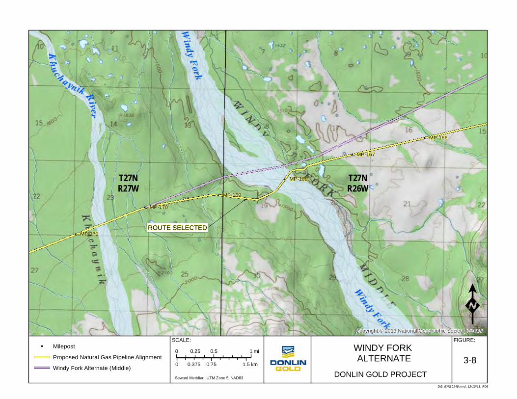
ROUTE SELECTED
MP-170
MP-169
MP-168
MP-167
MP-171
MP-166
T27NR27W
T27NR26W
Copyright:© 2013 National Geographic Society, i-cubed
WINDY FORK ALTERNATE
0 0.75 1.50.375 km
FIGURE:SCALE:
DG: ENG0146.mxd, 12/10/13, R06
0 0.5 10.25 mi
DONLIN GOLD PROJECT
3-8Milepost
Proposed Natural Gas Pipeline Alignment
Windy Fork Alternate (Middle)Seward Meridian, UTM Zone 5, NAD83

ROUTE SELECTEDMP-198
MP-190
MP-197
MP-189
MP-194
MP-193
MP-196
MP-188
MP-195
MP-192
MP-191
T26NR31W T26N
R30WT26NR29W
T25NR30W
T25NR31W T25N
R29W
3435 36 31 32 33 34 35 36 31 32
3 2 1 6 5 4 3 2 1 6 5
10 11 12 7 8 9 10 11 12 7 8
15
14 13 18 17 16 1514
13 18 17
22
23 24 19 2021
2223 24 19 20
27 26 25 30 29 28 27 26 25 30 29
34
35 36 31 32 33 34 35 36 31 32
5 4 3 2 Copyright:© 2013 National Geographic Society, i-cubed
BIG RIVER ALTERNATE0 0.8 1.60.4 km
FIGURE:SCALE:
DG: ENG0147.mxd, 12/10/13, R09
0 0.5 10.25 mi
DONLIN GOLD PROJECT
3-9
Milepost
Proposed Natural Gas Pipeline Alignment
Big River Alternate (North)
Big River Alternate (South) Seward Meridian, UTM Zone 5, NAD83

Tatlawiks
ukRiv
er
!!
!
!
!
&
ROUTE SELECTED
MP-217
MP-216
MP-215
MP-219
MP-218
T24NR34W
Copyright:© 2013 National Geographic Society, i-cubed
TATLAWIKSUK RIVERALTERNATES0 0.5 10.25 km
FIGURE:SCALE:
KDG: ENG0148.mxd, 12/10/13, R09
0 0.25 0.50.125 mi
DONLIN GOLD PROJECT
3-10
! Milepost
Proposed Natural Gas Pipeline Alignment
Tatlawiksuk Alternate (North)
Tatlawiksuk Alternate (South) Seward Meridian, UTM Zone 5, NAD83
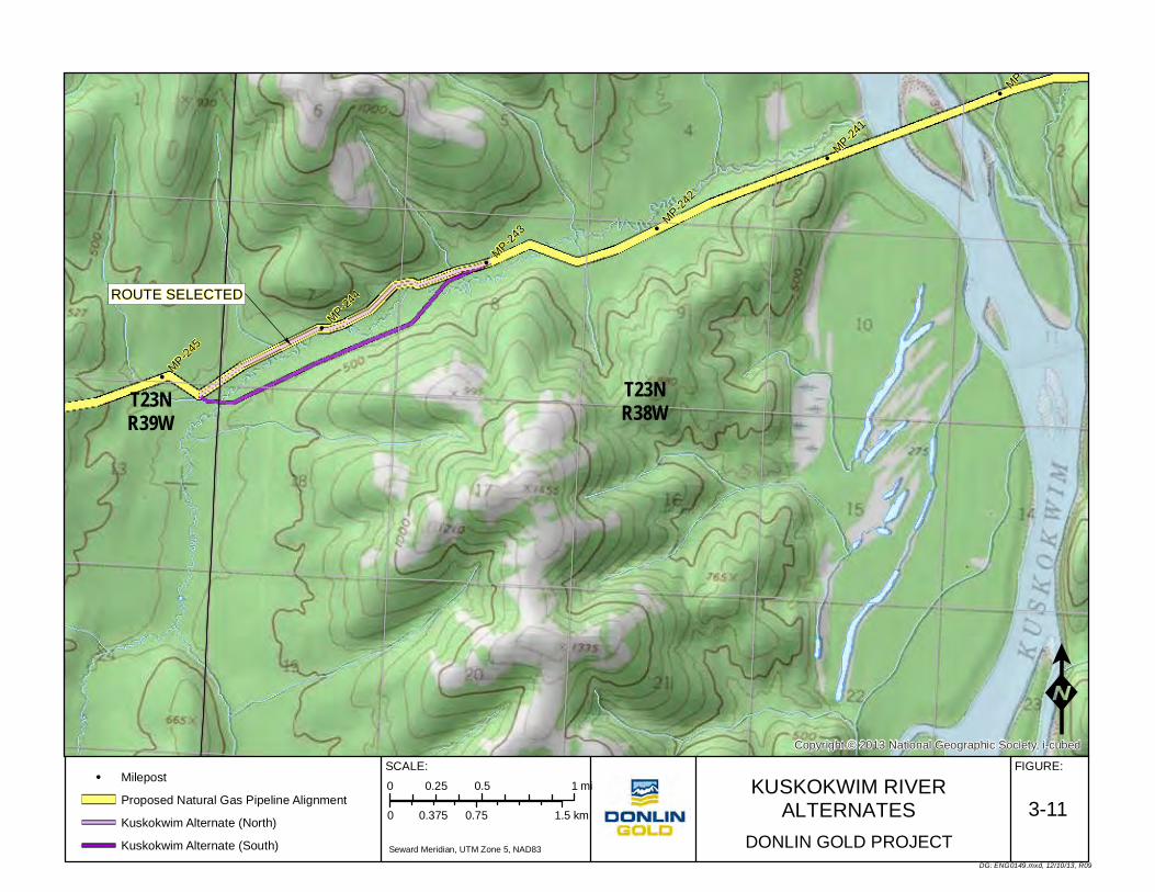
MP-240
MP-245
MP-244
MP-243
MP-242
MP-241
T23NR38WT23N
R39W
Copyright:© 2013 National Geographic Society, i-cubed
KUSKOKWIM RIVERALTERNATES0 0.75 1.50.375 km
FIGURE:SCALE:
DG: ENG0149.mxd, 12/10/13, R09
0 0.5 10.25 mi
DONLIN GOLD PROJECT
3-11
Milepost
Proposed Natural Gas Pipeline Alignment
Kuskokwim Alternate (North)
Kuskokwim Alternate (South) Seward Meridian, UTM Zone 5, NAD83
ROUTE SELECTED

ROUTE SELECTED
ROUTE SELECTED
ROUTE SELECTED
MP-264
MP-259
MP-263 MP-26
2
MP-267 MP-26
6
MP-261
MP-260
MP-265
T22NR41W T22N
R40W
T23NR42W T23N
R41W
T22NR42W
Copyright:© 2013 National Geographic Society, i-cubed
MOOSE CREEK ALTERNATES0 0.75 1.50.375 km
FIGURE:SCALE:
DG: ENG0150.mxd, 12/10/13, R08
0 0.5 10.25 mi
DONLIN GOLD PROJECT
3-12
Milepost
Proposed Natural Gas Pipeline Alignment
Moose Creek Alternate (Short)
Moose Creek Alternate (Long)

EastFork George River
East Fork George River
Eas t Fork George River
South Fork George RiverGeorge R iver
G eorge
River
North Fork George River
G eorge R
iver
North
Fork
George River
Steam
boat
Creek
ROUTE SELECTED
MP-291
MP-296
MP-281
MP-286
MP-295
MP-300
MP-285
MP-290
MP-280
MP-299
MP-304
MP-289
MP-294
MP-279
MP-284
MP-303
MP-293
MP-298
MP-283
MP-288
MP-278
MP-297
MP-302
MP-287MP-29
2
MP-277
MP-282
MP-301
T23NR45W
T23NR47W
T23NR46W
T22NR45W
T23NR43W
T24NR47W T24N
R45WT24NR43W
T23NR44W
T24NR44W
T24NR46W
T21NR46W
T22NR46W
T21N R45WT21NR47W
T22NR47W
T22NR44W T22N
R43W
Copyright:© 2013 National Geographic Society, i-cubed
KUSKOKWIM HILLSALTERNATES0 3 61.5 km
FIGURE:SCALE:
DG: ENG0151.mxd, 12/10/13, R08
0 2 41 mi
DONLIN GOLD PROJECT
3-13
Milepost
Proposed Natural Gas Pipeline Alignment
Kuskokwim Hills Alternate (North 100518)
Kuskokwim Hills Alternate (North 100526)
Kuskokwim Hills Alternate (South) Seward Meridian, UTM Zone 5, NAD83
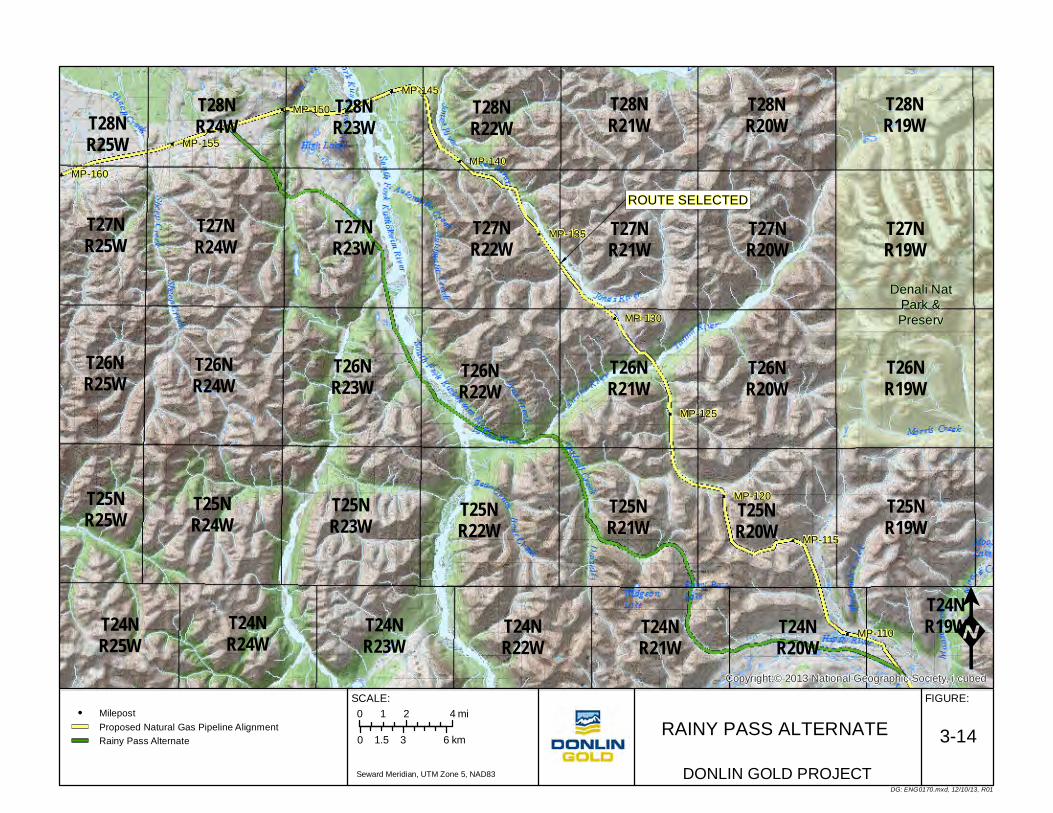
ROUTE SELECTED
Denali NatPark &Preserv
MP-160
MP-115
MP-120
MP-110
MP-150
MP-155
MP-140
MP-145
MP-130
MP-135
MP-125
T28NR25W
T26NR20W
T28NR21W
T28NR22W
T26NR21W
T26NR19W
T26NR22W
T26NR23W
T28NR19W
T28NR20W
T26NR24W
T27NR24W
T27NR25W
T28NR23W
T27NR21W
T26NR25W
T27NR19W
T27NR20W
T28NR24W
T27NR22W
T27NR23W
T24NR22W
T24NR21W
T24NR23W
T25NR19W
T25NR23W
T25NR24W
T24NR24W
T24NR25W
T24NR20W
T24NR19W
T25NR21W
T25NR25W T25N
R20WT25NR22W
Copyright:© 2013 National Geographic Society, i-cubed
RAINY PASS ALTERNATE0 3 61.5 km
FIGURE:SCALE:
DG: ENG0170.mxd, 12/10/13, R01
0 2 41 mi
DONLIN GOLD PROJECT
3-14MilepostProposed Natural Gas Pipeline AlignmentRainy Pass Alternate
Seward Meridian, UTM Zone 5, NAD83

ROUTE SELECTEDDenali Nat
Park &Preserv
MP-160
MP-115
MP-120
MP-110
MP-150
MP-155
MP-140
MP-145
MP-130
MP-135
MP-125
T28NR25W
T26NR20W
T28NR21W
T28NR22W
T26NR21W
T26NR19W
T26NR22W
T26NR23W
T28NR19W
T28NR20W
T26NR24W
T27NR24W
T27NR25W
T28NR23W
T27NR21W
T26NR25W
T27NR19W
T27NR20W
T28NR24W
T27NR22W
T27NR23W
T24NR22W
T24NR21W
T24NR23W
T25NR19W
T25NR23W
T25NR24W
T24NR24W
T24NR25W
T24NR20W
T24NR19W
T25NR21W
T25NR25W T25N
R20WT25NR22W
Copyright:© 2013 National Geographic Society, i-cubed
JONES ALTERNATE 0 3 61.5 km
FIGURE:SCALE:
DG: ENG0171.mxd, 12/10/13, R01
0 2 41 mi
DONLIN GOLD PROJECT
3-15MilepostProposed Natural Gas Pipeline AlignmentJones Alternate
Seward Meridian, UTM Zone 5, NAD83

"
"
"
"
"
"
"
""
"""
"
"
"
Existing Pretty Creek RoadCorridor
Exist
ing N
atur
alGas
Pip
eline
Point In Common
&
&
ROUTE SELECTED
SUSITNAFLATS STATE
GAME REFUGEMP-0
MP-1
MP-2
MP-3
MP-4
MP-5
MP-6
MP-7
Copyright:© 2013 National Geographic Society, i-cubedK
DG: PER0402.mxd, 12/10/13, R04
SUSITNA FLATS STATE GAME REFUGE
GAS PIPELINE ALTERNATES
0 1.5 30.75 km
FIGURE:
0 1 20.5 mi
DONLIN GOLD PROJECTSCALE:
Seward Meridian, UTM Zone 5 NAD83
3-16
1 in = 1.25 mi
Proposed Gasline Milepost (MP-)
Proposed Pretty Creek Alternate
Pretty Creek Road Right-of-Way
East Theodore Alternate
Beluga Alternate
" Cook Inlet Existing Facility
Cook Inlet Existing Gasline
Cook Inlet Existing Oil Line
Game Refuge Boundary

Plan of Development Donlin Gold Project Project Description
Donlin Gold 3-39 December 2013
3.11 Safeguards for Persons, Property, Public and the Environment Donlin Gold is committed to conducting business in a manner that is compatible with the environment of the project area and that recognizes the concerns and needs of the general public in the area or using the area or traversing through the route in which the proposed pipeline would be constructed and operated. Donlin Gold intends to protect the safety, security, and health of its employees, those involved with the construction, operation, maintenance and termination of the proposed pipeline, and the public. Donlin Gold’s primary objectives are to establish and maintain the proposed pipeline’s integrity through leak prevention, surveillance, inspection and monitoring; to plan for response in the case of any emergency relating to the pipeline or workers during construction, operation, maintenance, and termination; and to fulfill all stabilization, rehabilitation and reclamation obligations.
The project is subject to strict state and federal laws that provide safeguards for persons, property, the public and the environment. Project specific permits and authorizations are required under state and federal laws for construction, operation, maintenance, and termination of the pipeline project. Critical permits and authorizations required for this project are the State Pipeline Right-of-Way Lease under Alaska Statutes (AS) 38.35; BLM Grant of Right-of-Way; CWA Section 404 permit from the USACE; PHMSA special permit; CWA Section 401 certification from the Alaska Department of Environmental Conservation (ADEC); and, fish habitat and protection permits from the Alaska Department of Fish and Game (ADF&G). Other permits and authorizations support the issuances of the ROW lease and grant as well as the approved plans and programs necessary for construction, operation, maintenance and termination of the project.
3.11.1 Safety of Workers Donlin Gold would implement a worker safety plan program (Health, Safety and Environment Plan) for the proposed pipeline project construction, operation, maintenance and termination that also would address the safety of workers. Safety considerations during construction are discussed in Sections 8.1.18, 8.10 and safety considerations during operations and maintenance in Section 11.3.
Before being dispatched to the field, all personnel would receive health, safety, and environment (HSE) training. The training program would focus on applicable state and federal regulations as well as project-specific permit conditions and mitigation plans. The training would include environmental and cultural sensitivity issues. A project orientation would be conducted that would focus on personnel safety and health, camp rules, prohibited items (for example, pets, drugs, alcohol, and firearms), mobilization, wildlife interaction, waste management, medical and emergency response, fire prevention and suppression and related topics. Safety training would be a major component of the orientation. Other plans would be developed that would include the safety of workers such as a Fire Prevention and Suppression Plan, and Wildlife Avoidance and Human Encounter/Interaction Plan (see Section 3.11.9 for a list of some plans).
A compliance monitoring program would be used during all project phases. Components of the program would include:
• Conveying regulatory requirements to Donlin and contractor personnel • Establishing a compliance matrix that describes routine permit related inspections
and other activities

Plan of Development Donlin Gold Project Project Description
Donlin Gold 3-40 December 2013
• Implement a Permits and Environmental Compliance Monitoring Program to verify commitments are met
An Emergency Response Plan would be developed to identify potential hazards and applicable corrective actions. Specific emergencies that would be addressed include at least the following:
• Serious illness or injury • Fatality • Fire or explosion • Pipeline rupture or emergency • Earthquake/other natural occurrences • Wildfires • Bomb threat, vandalism, sabotage or other criminal act
3.11.2 Public Health and Safety Design, administrative, and operational controls would be developed and implemented to prevent and abate hazards and to protect the health and safety of all persons affected by the activities performed in connection with the construction, operation, maintenance and termination of the pipeline.
A threat or hazard to public health and safety associated with release of natural gas would exist only during operation of the pipeline. There are no other significant events that have been identified that pose serious hazards to public health and safety during the construction phase provided that the public also exercises reasonable caution, remains alert to on-going construction activities, and obeys hazard warnings or directions when nearing or traversing construction areas or temporary use areas even if construction personnel may be aware of their presence or assisting them through an area under restricted access during construction. There is the potential hazard of a construction-related fire or blasting incident however, the construction contractors would also be required to address such circumstances and take necessary precautions to avert potential risks to public health and safety.
Construction and Operations Practices Established safe construction practices, together with health and safety programs, would be used to protect the health and safety of the workforce and the public during construction and operation of the pipeline. Donlin Gold would observe and comply with applicable federal, state, and local laws and regulations related to public health and safety, including federal regulations pursuant to 49 CFR 192. These federal regulations provide stringent standards for pipe materials, pipe design, pipe components, pipe welds, pipeline construction, corrosion protection, pipeline pressure testing, and operations and maintenance.
Access Limited potential exists for general public access to the pipeline ROW because of the remoteness of the area and the seasonal means of transportation to the ROW. Donlin Gold recognizes that the portion of the pipeline project in the Matanuska Susitna (MatSu) Borough receives regular winter use from Anchorage, MatSu Borough and local area residents and that this use would be temporarily interrupted by the project. Through its Public Outreach Plan and in coordination with the applicable agency/landowner, Donlin Gold

Plan of Development Donlin Gold Project Project Description
Donlin Gold 3-41 December 2013
would provide notice of pipeline construction activities and information on how the public could coordinate access needs with construction activities. In these and other areas where construction activities would affect existing access routes Donlin Gold would provide alternate access or allow for controlled access within or across the construction area. This would include ADL 222930/RST-199, the main transportation route in the region.
Donlin Gold would discourage public use the ROW during pipeline operation if it potentially put the integrity of the pipeline system at risk. During construction, a “controlled access” policy would be implemented. Through its Public Outreach Plan Donlin Gold would provide information regarding pipeline construction, operation, maintenance and termination activities and on how the public could coordinate access needs with these activities. In areas where these activities would affect existing access routes Donlin Gold would provide alternate access or allow for controlled access within or across the area of the pipeline where construction activities were occurring. Communities/villages in the general area as well as events operating annually under permit along the Iditarod Trail (including the Irondog Snowmachine Race, Iditarod Trail Sled Dog Race, and Iditarod Trail Invitational) would be consulted or included in communications about construction, operation, maintenance and termination activities in order to avoid potential conflicts with subsistence users, local travelers, and event trail users. Appropriate notices, warning signs, flagging, barricades, and other safety measures would be used to facilitate pipeline construction, operation, maintenance and termination activities, and to protect the public and wildlife from hazards associated with pipeline construction, operation, maintenance, and termination activities. Any existing roads, trails (including RS-2477s) or other public improvements encountered during construction, operation, maintenance and termination would be protected and if damaged restored to the extent possible including provisions for suitable permanent crossings where the ROW crosses existing trails. Refer to Section 11.9.5 for information regarding heavy equipment pipeline crossing.
Donlin Gold would prohibit its employees and contractors from operating project related equipment off the pipeline ROW or any of the other authorized temporary use areas or material borrow sites.
Spills and Leaks Risks relating to spills or leaks of fuel during pipeline construction or operation would be reduced by implementing appropriate and effective inspection, maintenance, monitoring and response programs.
Inspections and Maintenance Measures to protect public health and safety during pipeline operation include an ongoing inspection and maintenance program as part of regulatory compliance and the Pipeline Surveillance and Monitoring Plan as well as the Operation and Maintenance Plan/Manual (O&M Plan/Manual).
Pipeline The pipeline would be buried except where the pipeline would cross two active faults each for a distance of approximately 1,400 ft (427 m) and as required by geotechnical design considerations through the Alaska Range. There would also be control valves located at no greater than 20 mile (32 km) intervals along the pipeline, and a pigging station, metering station and compressor station. Thus, there would be very limited exposure to the pipeline itself along the ROW.

Plan of Development Donlin Gold Project Project Description
Donlin Gold 3-42 December 2013
Signage Signs would be placed at appropriate locations along the pipeline in compliance with regulatory requirements, including locations required by 49 CFR 192, warning the public of associated hazards and providing the operator’s name and 24-hour–a-day contact information or as additionally determined appropriate by Donlin Gold for safety purposes. Because the pipeline would cross state, federal, CIRI and Calista lands as well as being located in part within borough boundaries additional signage may be required beyond that required by 49 CFR 192. Donlin Gold would coordinate the development of a Signage Plan or strategy with the appropriate entities to address concerns if signage became an issue. See also Sections 6.11, 8.12, and 11.5.
Public Outreach/Public Awareness Donlin Gold would establish a Public Outreach Plan with the communities and trail users in the general area through which public safety concerns, access to the area for subsistence use, emergency assistance, and other trail use and safety-related travel issues would be addressed. The public would be able to obtain information and be aware of ongoing activities prior to traveling in construction areas as well as what procedures to follow for contacting Donlin Gold regarding access across or along the construction area. See Section 8.1.7.
3.11.3 Public or Private Property A small number of private parcels exist adjacent to the proposed pipeline ROW. Efforts were made to route the pipeline so as not to cross privately owned parcels. Within the proposed ROW there are lands owned by Calista and CIRI. Arrangements would be necessary to traverse these lands with the pipeline. All remaining lands are public lands managed by the state or federal government.
Cook Inlet Energy, LLC holds Oil and Gas Lease ADL 390749 between approximately MP 2.8 and MP 6.1 and Hilcorp Alaska, LLC holds Oil and Gas Lease ADL 63048 at the beginning of the pipeline from approximately MP 0 to about MP 1.2. From MP 0 to approximately MP 5.1 the pipeline is within the SFSGR. More detailed land status information is provided in Appendix A.
Any existing roads, trails (including RS-2477s) or other public improvements encountered during construction, operation and maintenance would be protected and if damaged restored to the extent possible for continued use. Alternate access would be provided when existing access is blocked for construction, operation, maintenance, and termination activities. Alternative access would be determined on case-by-case bases. No trails or roads would be intentionally blocked along the pipeline ROW unless specifically authorized by the applicable agency/landowner.
Major events that potentially could cause serious and irreparable harm or damages to public or private property would be a result of a pipeline rupture and explosion or a major fuel spill. An explosion, fuel spill or construction or maintenance incident could result in harm or damage including a fire effecting nearby public or private property and/or loss of life. An Emergency Response Plan would be developed to address such potential hazards and corrective/response actions.

Plan of Development Donlin Gold Project Project Description
Donlin Gold 3-43 December 2013
Specific plans and procedures would be developed to identify monitoring, inspections, quality control, and reporting requirements during and following construction. See Section 3.11.9 for additional information.
During Construction During construction, impacts would be avoided, minimized, and/or mitigated by various methods, including the following:
• Compliance with applicable state and federal regulations and permits issued for the project, and adherence to approved plans associated with the project
• Scheduling of winter construction to minimize damage to land cover, wetlands and waterbodies
• Construction inspection and monitoring by trained personnel to minimize unnecessary disturbance to construction areas
• Develop and implement appropriate plans to address and monitor construction activities
During Operation and Maintenance During operation and maintenance, impacts would be avoided, minimized, and/or mitigated by various methods, including the following:
• Donlin Gold would ensure compliance with state and federal applicable regulations and permits, and adherence to approved plans associated with the project
• The pipeline would be inspected and monitored regularly during operations, including and adherence to approved plans associated with the project
• Planned or unplanned pipeline repairs or maintenance would be completed in a manner that would minimize impacts to public or private property
• After construction, pipeline surveillance, inspection, and monitoring programs as well as a maintenance program would be implemented. The goals of these programs would not only be to uphold pipeline operating integrity and safety, but to also prevent, identify, and respond to all situations that pose a significant risk of damage to the environment
During Termination As stated in Section 12.1, a detailed Pipeline Abandonment Plan and procedures would be developed prior to termination of pipeline operations. Abandonment procedures would be based on applicable regulatory requirements at the time and would be designed to minimize impacts to public and private property in coordination with the landowner and regulatory agencies.
For additional information regarding land status along the proposed pipeline route refer to Appendices A and B.
3.11.4 Vegetation or Timber The primary incidents that could result in serious harm or damage to vegetation include fire that spreads to adjacent vegetation or spills of fuel or other liquids that could kill or damage vegetation. Inappropriate handling of vegetation or timber could also result in potential infestation of bark beetles, erosion and sedimentation issues, and debris in streams. Equipment used during construction may also result in damage to vegetative cover. If there was a stabilization, rehabilitation or reclamation failure, vegetation may be affected

Plan of Development Donlin Gold Project Project Description
Donlin Gold 3-44 December 2013
depending on the location and extent of damage. Donlin Gold would take all actions necessary and appropriate for the prevention and suppression of fires in accordance with applicable law and instructions from appropriate authorities. Wildfires would be reported to 1-800-237-3633 as would be required by the Fire Prevention and Suppression Plan.
Donlin Gold would also implement an Invasive Species Prevention and Management Plan to address existing invasive species as well the potential for introduction of invasive species in the project area. Following the Invasive Species Prevention and Management Plan would assist in preventing the introduction of invasive species to the project area by following approved procedures and best management practices (BMPs) prior to personnel, equipment and materials entering the project area and at locations of arrival and departure from the project area. Also procedures would require that BMPs be followed in construction, operation, maintenance and termination activities within the project area to prevent the spread of existing invasive species. Donlin Gold would complete a baseline survey for invasive species prior to construction.
Prior to any clearing operations Donlin Gold would notify the appropriate authority of the amount of merchantable timber, if any, which would be cut, used for construction purposes, made available for others, or destroyed. All work would be performed in accordance with relevant permit and lease stipulations and in a manner to prevent infestation of bark beetles or other potential problems consistent with the Donlin Gold Timber Clearing and Utilization Plan.
Donlin Gold anticipates that the majority of timber cut from the construction ROW would be used during construction or in reclamation, however if timber is available Donlin Gold would review reasonable and practicable options for disposal of remaining timber consistent with the Timber Clearing and Utilization Plan.
3.11.5 Fish or Other Wildlife or Their Habitat All debris resulting from clearing operations and construction that may block stream flow, impair or delay fish passage, contribute to flood damage, or result in streambed scour or erosion would be removed.
Logs would not be skidded or yarded across any watercourses or stored within 300 ft (91 m) of any watercourse without approval from appropriate authorities.
Appropriate plans, including the Wildlife Avoidance and Human Encounter/Interaction Plan, the Erosion and Sedimentation Control Plan (Appendix H), other applicable plans listed in Section 3.11.9 and construction and operating procedures would be in place to protect fish, wildlife and their habitats. Construction, operation, maintenance and termination activities would be carried out following approved plans and consistent with the regulatory requirements and the stipulations of federal and state authorizations.
Construction of stream crossings on streams with anadromous fish would follow plans and design measures that would reduce impacts to migrating fish and to spawning habitat.
Donlin Gold would prohibit its employees and contractors from hunting, fishing, trapping, shooting, and camping within or adjacent to the ROW or using project equipment for those purposes while they are in the project area for work-related purposes.
Following construction, the pipeline ROW project area would be reclaimed consistent with the approved Stabilization, Rehabilitation, and Reclamation Plan and would not significantly

Plan of Development Donlin Gold Project Project Description
Donlin Gold 3-45 December 2013
restrict wildlife crossing the ROW except in locations where the pipeline is aboveground. The ROW would be available for use by wildlife.
All temporary construction bridges, culverts and other structures would be removed consistent with the Stabilization, Rehabilitation, and Reclamation Plan.
3.11.6 Restoring Areas of Vegetation or Timber Areas of vegetation or timber damaged or harmed directly or indirectly by the construction, operation, maintenance or termination of all or any part of the proposed pipeline would be identified and corrective action taken, as appropriate and consistent with the approved Stabilization, Rehabilitation and Reclamation Plan, other applicable plans and regulatory requirements or if outside of the area authorized for construction, as agreed with the landowner. Corrective action would typically involve documenting the specific location of the damage, conducting an inspection and rehabilitating and reclaiming the disturbed area in a manner approved by the applicable regulatory agencies or landowner. Design and construction measures would be taken to avoid unnecessary damage to the project area and adjacent land.
If any vegetative restoration activities were required, only Alaska State Certified Seed and erosion control products made from Certified Weed Free materials (seed mix, mulch, etc.) would be used if available. Monitoring for and management of invasive species would be carried out consistent with the approved Invasive Species Prevention and Management Plan.
During Construction All areas of the construction ROW would be stabilized, rehabilitated and reclaimed consistent with state and federal law and the approved Stabilization, Rehabilitation and Reclamation Plan for the proposed pipeline project. If it became necessary to restore an area outside of the construction area authorized, such work would be accomplished as agreed with the appropriate agency or landowner.
During Operation and Maintenance For operation and maintenance as well as for safety purposes the 50 ft (15 m) permanent ROW on state, CIRI, and Calista lands and 51 ft 2 inches (15.6 m) ROW on federal land would be cleared of shrubs at approximately 10-year intervals or as required to preserve pipeline integrity and allow for ongoing surveillance and monitoring activities as well as maintenance as may be required. During operation and maintenance any unplanned damage to the vegetation resulting from pipeline activities would be identified and corrective action taken to stabilize and rehabilitate the disturbed area, as appropriate for the situation identified and following applicable plans, procedures and regulatory requirements or if outside of the area authorized, as agreed with the appropriate agency or landowner.
3.11.7 Erosion and Rehabilitation of Areas Eroded All areas of the construction ROW would be stabilized, rehabilitated and reclaimed consistent with applicable state and federal laws and the land owner approved Stabilization, Rehabilitation and Reclamation Plan and Erosion and Sedimentation Control Plan for the proposed pipeline project.
Plan of Development Donlin Gold Project Project Description
Donlin Gold 3-46 December 2013
The Erosion and Sedimentation Control Plan provided in Appendix H would specifically define erosion control procedures to be applied along the pipeline ROW. In addition, a Storm Water Pollution Prevention Plan (SWPPP) would be developed as required by the APDES permit. This would address erosion control measures, reclamation and mitigation measures to control erosion and storm water runoff during and after construction. Continued ground surveillance and corrective erosion control and vegetation maintenance would be employed throughout construction of the project. Normal drainage patterns would be maintained where practical. The Stabilization, Rehabilitation and Reclamation Plan, the Erosion and Sedimentation Control Plan, and final design plans would include BMPs and storm drainage design to control surface flow along the crowned trench and the project ROW where necessary. All sedimentation control devices and materials would be made from Alaska Certified Weed Free material- straw, hay, and gravel certification programs are available in Alaska.
Plan Compliance by Contractors and Subcontractors
Donlin Gold would require its personnel, contractors and subcontractors to adhere to all permit stipulations and regulations, as well as to Donlin Gold’s policies, procedures, applicable plans, including but not limited to, the Invasive Species Prevention and Management Plan, and expectations. Compliance would be accomplished by contractual terms, contractor management, and compliance with Donlin Gold plans and programs, including the following:
• A contractor qualification review before contract award. This would include evaluation of their performance in meeting past HSE requirements, in addition to other qualifying factors.
• Meetings with contractors to identify clarify and discuss expectations and requirements for their HSE performance and to identify any of Donlin Gold’s additional requirements.
• Donlin Gold plans or programs that contain requirements for inspections and audits of pipeline construction, operation, and maintenance, including those requirements that are the responsibility of contractors to adopt and enforce.
• Provisions incorporating safeguards, procedures and stipulations of the various ROW authorizations and approved plans, and required compliance with those safeguards, procedures and stipulations, would be incorporated into contracts and as appropriate, subcontracts for construction, operation, and maintenance of the pipeline.
• Any contractor or subcontractor found in non-compliance with stipulations and requirements of the federal and state ROW authorizations and regulations and/or Donlin Gold’s approved pipeline plans and applicable policies, may be subject to disciplinary action.
A Permits and Environmental Compliance Program would be prepared for project use during construction, operation, maintenance and termination. The purpose of the program would be to facilitate compliance with project permits and applicable environmental laws and regulations. The program would be prepared after project permits and other authorizations are obtained so that permit obligations and requirements can be included in the program and explained and used in the field. The program would provide procedures for permit and regulatory compliance, including the requirements of the ROW authorizations, reporting, monitoring, and any plans. In addition, the program would detail Donlin Gold’s environmental policies and performance expectations. See Sections 8.11 and 11.16.

Plan of Development Donlin Gold Project Project Description
Donlin Gold 3-47 December 2013
3.11.8 Quality Control and Procedures for Inspecting and Testing the Pipeline The proposed Donlin Gold natural gas pipeline would be designed, constructed, operated, and maintained in accordance with the requirements of the PHMSA within the USDOT and applicable authorization requirements. These requirements are intended to ensure the safe transportation of natural gas, including adequate protection for the public from natural gas pipeline failures. The proposed Donlin Gold pipeline would meet or exceed these requirements.
Donlin Gold would adhere to its Operations Integrity Management System safeguards and stipulations. To facilitate compliance with the safeguards and stipulations of the ROW authorizations, all contractors would be pre-qualified to verify that they have an Integrity Management System or equivalent in place. In addition, Donlin Gold would implement a Quality Management Program that would:
• Apply to and remain in effect during construction, operation, maintenance and termination
• Identify the processes needed to be undertaken and the methodologies followed for effective processes
• Verify resources are dedicated to support the operation and monitoring of the processes
• Monitor, measure, and analyze processes and implement corrective actions to processes if necessary
The Quality Management Program would include a Quality Manual and Quality Control Plan including policies and objectives. Donlin Gold, including its agents, employees, and contractors would comply with the approved Quality Management Program. This program in conjunction with the Permits and Environmental Compliance Program would serve to identify any potential issues and verify that all work is performed in a manner to maintain the quality of the pipeline and related facilities, and to make sure all work is performed in accordance with relevant permit and lease stipulations.
The O&M Plan/Manual and Pipeline Surveillance and Monitoring Plan would provide more detailed information on proposed inspection and monitoring procedures. A detailed Pressure Testing Plan would be prepared during final design. See Sections 8.6.25 and 8.11 for more information. The Invasive Species Prevention and Management Plan would apply to the entire project area once approved by the involved landowners.
Project activities planned to accomplish overall pipeline quality objectives are described below.
Field Design Changes As in any project, there may be a need for unanticipated design changes in the field during the actual pipeline construction process. These design changes are the result of the conditions encountered along the route that dictate the necessity for the change. Such field design changes when approved and implemented would be documented on the appropriate drawings and in the applicable specifications. Procedures would be developed and used during project construction and operation for documenting and maintaining these records.
Construction Inspection Inspections would be conducted in accordance with the Pipeline Integrity Management System and approved contractor Quality Assurance and Control Plans. In addition, a system

Plan of Development Donlin Gold Project Project Description
Donlin Gold 3-48 December 2013
would be developed and implemented to react quickly and efficiently to any deviations from identified standards. Inspectors trained and qualified would monitor construction activities. A set of complete records would be kept for future reference during pipeline operation and maintenance and for future projects involving the pipeline.
Pipeline Materials and Procedures Control Materials that would be used in construction of the pipeline would meet the required specifications and pipeline standards. Appropriate quality control would be required of all pipeline material suppliers. Field welds on the pipeline would be inspected using non-destructive testing during construction. Inspectors would be employed to verify compliance with the approved welding procedures and conformance to other construction practices, standards, and requirements.
Pipeline Operations and Maintenance When the pipeline is in operation, the pipeline would be periodically inspected using in-line inspection tools- intelligent inspection pigs. The O&M Plan/Manual and Pipeline Surveillance and Monitoring Plan would provide details about inspection pigging, and would define the types and frequency of inspection pigs to be run through the pipeline. The first inspection pig run would establish baseline pipeline conditions. Subsequent pig runs would be scheduled to monitor and detect changes from the baseline conditions. The need for and frequency of the pig runs would be evaluated based on results from previous pig runs and on operating experience and requirements. Please refer to Section 11.10.
3.11.9 Special Safeguards to Protect the Interests of Individuals Living in the General Area for Subsistence Purposes
Plans and procedures to protect the interests of individuals living in the general area of the proposed ROW who rely on the fish, wildlife and biotic resources of the area for subsistence purposes would be integrated into the general construction, operation, maintenance and termination activities.
Donlin Gold’s proposed mitigation measures for impacts to subsistence activities would be addressed in its Subsistence Users Plan of Cooperation. This Plan would:
• Identify locations where subsistence activities occur, and coordinate activities in these areas to the maximum extent practicable during the short span of construction activities
• Attempt to limit or reduce conflict with subsistence activities when possible • Notify workers that subsistence activities are or may be ongoing in an area and
direct them to limit or reduce to the extent practicable actions that may affect the activities
• Develop and implement a Wildlife Avoidance and Human Encounter/Interaction Plan for the construction, operation, maintenance and termination of the pipeline to avoid or minimize impacts to subsistence species whenever possible especially during the short duration of construction
Donlin Gold would develop a number of plans and procedures for construction, operation, maintenance and termination of the proposed project, many of which would apply directly or indirectly to protect the environment, including fish, wildlife, and biotic resources that are used for subsistence and subsistence activities. Donlin Gold or its contractors would develop the necessary plans and procedures for appropriate review and approval prior to

Plan of Development Donlin Gold Project Project Description
Donlin Gold 3-49 December 2013
receiving a notice to proceed with construction or as otherwise required by the appropriate agency/landowner. The following are some of the plans and procedures that would be developed and implemented. In some cases, these plans may be combined:
• Quality Control Plan • Site Security Plans • Spill Prevention, Control and Countermeasure Plan (SPCC) • Facility Response Plan (FRP) • Erosion and Sedimentation Control Plan ( PoD Appendix H) • Storm Water Pollution Prevention Plan • Material Site Mining and Reclamation Plans • Blasting Plan • Wildlife Avoidance and Human Encounter/Interaction Plan • Comprehensive Waste Management Plan • Stabilization, Rehabilitation, and Reclamation Plan • Invasive Species Prevention and Management Plan • Timber Clearing and Utilization Plan • Operations and Maintenance Plan/Manual • Fire Prevention and Suppression Plan • Emergency Response Plan • Public Outreach Plan • Pipeline Surveillance and Monitoring Plan • Health, Safety and Environment Plan (Includes Safety Plan/Program) • Subsistence Users Plan of Cooperation • Commercial Lodges Plan of Cooperation • Annual Report to State Pipeline Coordinator’s Office (SPCO)
A SCADA system would be implemented to collect measurements and data along the pipeline, including flow rate through the pipeline, operational status, pressure, and temperature readings.
3.11.10 Special Safeguards to Protect the Interests of Commercial Lodges Plans and procedures to protect the interests of commercial lodges in the general area of the proposed ROW would be integrated into the general construction, operation, maintenance and termination activities when reasonable and where practicable. Table 3-5 and Figure 3-17 identify lodges within five miles of the proposed ROW.
Donlin Gold’s proposed mitigation measures for impacts to commercial lodge operations would be addressed in its Commercial Lodges Plan of Cooperation.
This Plan would:
• Identify locations where commercial lodges operations occur, and coordinate activities in these areas to the maximum extent practicable during the short span of construction activities
• Attempt to schedule work to limit or reduce potential conflict with commercial guiding/lodge activities when possible recognizing that construction must be

Plan of Development Donlin Gold Project Project Description
Donlin Gold 3-50 December 2013
scheduled taking into account seasonal and environmental conditions and may interfere with lodge activities in the proximity of the ROW
• Notify workers that commercial lodge activities are or may be ongoing in an area and direct them to limit or reduce actions to the extent practicable that may affect the activities
Donlin Gold would develop and implement a Wildlife Avoidance and Human Encounter/Interaction Plan for the construction and operation of the pipeline to avoid or at least limit impacts to specific species especially during the short duration of construction when encounters are most likely to occur.

Plan of Development Donlin Gold Project Project Description
Donlin Gold 3-51 December 2013
Table 3-5: Commercial Lodges
COMMERCIAL LODGES WITHIN 5 MILES (8 km) OF PROPOSED PIPELINE CORRIDOR
Name Location Distance from Alignment
Main Season Type of Business
TalVista Lodge 61.8610 N 151.4048 W
1.8 mile (2.9 km) Summer/Winter Guided fishing, snowmachining
Talaview Lodge 61.8607 N 151.3973 W
1.8 mile (2.9 km) Summer Guided fishing
TalStar Lodge 61.8575 N 151.3957 W
1.9 mile (3 km) Summer Guided fishing
Talachulitna River Lodge
61.8565 N 151.3904 W
1.9 mile (3 km) Summer Member owned fishing and recreation
Shell Lake Lodge 61.9483 N 151.5424 W
1.8 mile (2.9 km) Winter (Summer business is fly-in only)
Restaurant/bar, snowmachining
Winter Lake Lodge 61.9870 N 152.0766 W
0.8 mile (1.3 km) Summer/Winter (Current flight avoidance area around Finger Lake)
Heli-skiing/tours, fishing, Iditarod checkpoint
Rainy Pass Lodge 62.0904 N 152.7344 W
0.6 mile (1 km) Summer/Winter (Project lodging in 2010, 2011, 2012; otherwise flight avoidance area)
Guided hunting, recreation, Iditarod checkpoint
Farewell Lake Lodge
62.5417 N 153.6207 W
4.4 mile (7 km) Inactive (lodge and out buildings burned in 2010
Guided hunting, lodging
Alaska Adventure Vacations*
T26N, R21W, Section 15 NW ¼ of the SW ¼, SM
Site appears to be located outside of the proposed ROW
Seasonal recreation camp
ADNR, DMLW Permit (LAS 24564)
Hunting guide-outfitter operation*
T27N R27W, Section 26 (62o 23.806N 154o 13.343W)
Approximately 1 miles south of approximately MP 170 of the pipeline route (requesting to move lease site closer to the proposed pipeline route to BLM)
Commercial occupancy lease and associated airstrip
Big game hunting guide-outfitting operation
Other Commercial Guide Camps*
LAS 27588, LAS 24345
Refer to Figure 3-17 Commercial guiding
*Shown for informational purposes. Also see Appendix A for land status information.
.

!
!
!
!
! !
!
!
!
!
!
!
!
!
!
!
!
!
!
!
!
!
!
!
!
!
!
!
!
!
!
!
!
!
!
!
!
!
!
Windy Fork
South Fork KuskokwimR iver
Little Tonzona River
EastForkYentna River
Johnson Creek
Skwentna River
Deshka River
LakeCreek
Susitn
a River
West Fork Yentna River Ka h iltna River
Lake CreekTheodore R iver
Talachuli tna River
Yentna River
Hayes
River
Susitn
a Rive
r
Yentna River
Big River
Peter
s Cree
k
Tra p per Cr.
Montan a Creek
Moose
Creek
Trapper
Cr.
Camp Creek
Alexander Creek
Little
Susit
naRi
ver
Big Salm on River
RedShirtLake
Teshekpuk Lake
StrandlineLake
TrapperLake
GuitarLake
ChelatnaLake
ShellLake
BelugaLake
!=!=!=!=
!=!=
!=
!=
×Ö
×Ö
×Ö
×Ö×Ö
&SEE INSET
&
Farewell Lake Lodge
&
Alaska Adventure VacationsCommercial Guide CampLAS 24564
&Rainy PassLodge
&
Shell HillsLodge&
Winter Lake Lodge
&
Commercial Occupance LeasePhilip Esai & Jon Runkled/b/a Silvertip Guide ServiceAA-64705
&
Commercial Guide CampLAS 24345
&
Commercial Guide CampsLAS 27588 & LAS 29232
NANCYLAKE SRA
TALKEETNA RECRIVER
DENALI SP
ALEXANDERCREEK REC RIVER
TALACHULITNAREC RIVER
SUSITNAFLATS SGR
PETERSVILLEREC MINING
LAKE CREEKREC RIVER
KROTO & MOOSECREEK REC R
LAKE CLARKNP & P
LAKE CLARKNP & P
LAKE CLARKNP & P
DENALI NAT PARK& PRESERV
DENALI NATPARK &
PRESERV
DENALI NATPARK &
PRESERV
MP-190
MP-180 MP-17
0 MP-160
MP-40
MP-120
MP-110
MP-100
MP-90
MP-80 MP-70
MP-150
MP-60
MP-140
MP-50
MP-130
MP-30
MP-20
Petersville
Skwentna
Susitna
Farewell
LODGESWITHIN 5 MILES OF ALIGNMENT0 8 164 km
FIGURE:SCALE:
K
DG: PER0316.mxd, 12/10/13, R08
0 5 102.5 mi
DONLIN GOLD PROJECT
3-17
!= !=
!=!=
Copyright:© 2013 National GeographicSociety, i-cubed
TalVista LodgeTalaview Lodge
TalStar Lodge TalStar Lodge
INSET
0̄.5 mi
! Populated Place! Milepost
Proposed Natural Gas Pipeline Alignment
×Ö Commercial Guide Camp
!= Lodge Location
Seward Meridian, UTM Zone 5

Plan of Development Donlin Gold Project Right-of-Way Location
Donlin Gold 4-1 December 2013
4.0 Right-of-Way Location (ROW) 4.1 Legal Description The proposed pipeline alignment would cross federal, state, and Alaska Native Corporation lands. Appendix A provides land status information for the entire pipeline route. Appendix B identifies in detail each parcel by landowner along the construction corridor of the proposed ROW. Table 4-1 provides estimated acreage calculations for construction.
Two Alaska Native Regional Corporations own land traversed by the proposed pipeline and the proposed electric transmission line. Calista owns both surface and subsurface estate from approximately MP 310 to the pipeline terminus at the Donlin Gold mine site. CIRI owns surface and subsurface estate from approximately MP 150 to MP 156.2, which is located between the South Fork of the Kuskokwim River and the Sheep Creek/Farewell area as shown in Appendix A. CIRI also owns the surface estate, including sand and gravel near Beluga where the first four miles of the proposed power transmission line is located. Figure 4-1 shows the location of the potential construction use area for Beluga.
4.2 Site-specific Engineering Surveys for Critical Areas Site-specific engineering surveys are necessary for critical areas, defined as those areas requiring special design, such as areas with unstable slopes, river crossings, fault crossings, and high erosion potential.
Donlin Gold has conducted specialized surveys for the pipeline route and the results of these studies are summarized in Appendix C and Appendix D. Additional studies and the ongoing engineering and design work would be used to refine the optimal route, to identify construction methods, and to develop any specialized engineering design required for certain segments of the pipeline. Additional studies would continue as needed for detailed design. Currently available information was used in preparing PoD revision 1 (SRK 2013).
4.3 River Crossings A listing of stream and river crossings is provided in Appendix D. Typical drawings of stream crossings are included in Appendix E. Waterbody crossings are also discussed in more detail in Sections 8.1.4 and 8.6.15.
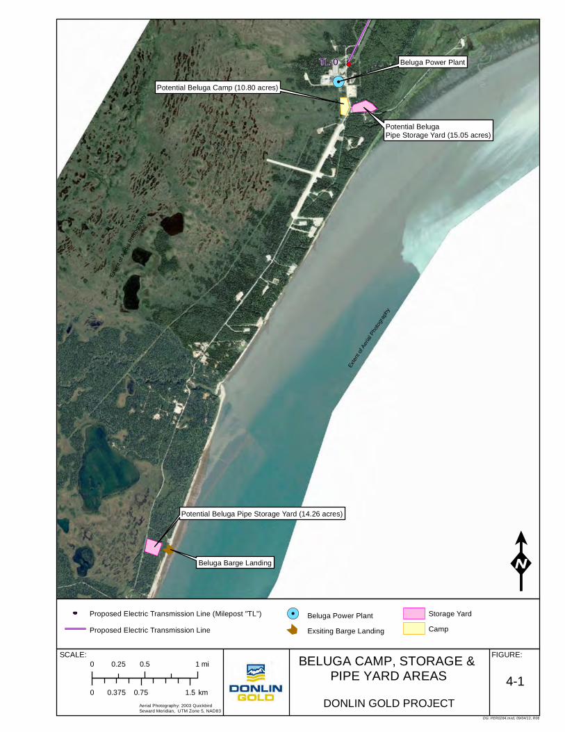
!.
Û
!(TL-0
Potential Beluga Pipe Storage Yard (14.26 acres)
Potential Beluga Pipe Storage Yard (15.05 acres)
Potential Beluga Camp (10.80 acres)
Beluga Power Plant
Beluga Barge Landing K
DG: PER0284.mxd, 09/04/13, R06
BELUGA CAMP, STORAGE & PIPE YARD AREAS
FIGURE:SCALE:
DONLIN GOLD PROJECT
4-1
Aerial Photography: 2003 QuickbirdSeward Meridian, UTM Zone 5, NAD83
Proposed Electric Transmission Line (Milepost "TL")
Proposed Electric Transmission Line
!. Beluga Power Plant
Û Exsiting Barge Landing
Storage Yard
Camp
0 0.75 1.50.375 km
0 0.5 10.25 mi
Exte
nt o
f Aer
ial P
hoto
grap
hy
Exte
nt of
Aer
ial P
hoto
grap
hy

Plan of Development Donlin Gold Project Right-of-Way Location
Donlin Gold 4-3 December 2013
4.4 Calculation of Estimated Right-of-Way Acreage Estimated total acreages for the state, federal and Alaska Native Claims Settlement Act (ANCSA) Corporation lands for the construction planning corridor are shown in Table 4-1. The actual ROW would be dictated by authorized construction requirements with necessary variance adjustments made in the field within the 300 ft (91 m) construction planning corridor on state, federal land, and CIRI lands. During construction, ancillary facilities, including access roads, laydown areas, airfields, borrow areas, and campsites, would require an additional estimated 2,585.5 acres (1,046.3 ha).
The 100 ft (30.5 m) temporary construction ROW area would be requested within the 300 ft (91 m) construction planning corridor which would parallel and adjoin the requested permanent ROW. The permanent ROW would be 50 ft (15.2 m) on state land, 51 ft 2 inches (15.6 m) on federal land and 50 ft (15.2 m) on ANCSA Corporation lands. The compressor station located on state land within the SFSGR would require an additional 1 acre (0.4 ha).
The electric transmission line easement would be approximately 8.1 miles long (13 km), of which approximately 7.7 miles (12.4 km) would be from the Beluga Power Plant to the metering station at MP 0, plus the distance of approximately 0.4 miles (0.6 km) to the compressor station at approximately MP 0.4, and 30 ft (9 m) wide, for an estimated 28.4 acres (11.5 ha). Of these, an estimated 14.3 acres (5.9 ha) are ANSCA Corporation lands and 14.1 acres (5.7 ha) are state lands.
Table 4-1: Estimated Acreage Calculation
Construction Planning Corridor and Ancillary Facilities
Estimated Length (miles)
300 ft Construction
Planning Corridor (acres)
Ancillary Facilities (acres)
Pipeline Federal Land 3,529.10 793.0 96.9 State Land* 7,503.9 1,713.1 206.6 ANCSA Land 424.6 79.4 11.7 Estimated Total: 11,457.7 2,585.5 315.2 Transmission Line
State Land 12.5 3.76** ANCSA Land 14.3 3.92 Estimated Total: 26.9 7.68** Compressor Station State Land 1 Note: Permanent ROW is 50 ft (15.2 m) on state land, 51 ft 2 in (15.6 m) on federal land and 50 ft (15.2 m) on ANSCA Land. It is anticipated that the fiber optic cable ROW would be 30 ft (9 m) wide and would be a separate authorization and is not included in this table. Transmission Line ROW would be 30 ft (9 m) on state and ANSCA lands. * State Land includes 5.1 miles of the SFSGR transected by the pipeline ** This distance and acreage is to the metering station. From metering station to compressor station is an additional estimated 0.4 miles (0.6 km). Estimated total length of transmission line is approximately 8.1 miles (13 km) and acreage is approximately 28.4 acres (11.5 ha).
Plan of Development Donlin Gold Project Pipeline Design Factors
Donlin Gold 5-1 December 2013
5.0 Pipeline Design Factors The design of the proposed pipeline would be in accordance with USDOT regulations under 49 CFR 192 – Transportation of Natural Gas and Other Gas by Pipeline: Minimum Federal Safety Standards. The pipeline would be designed, constructed and operated in accordance with the applicable requirements of 49 CFR 192 for subsurface pipelines and related appurtenances (compression stations, pig launching and receiving facilities, MLVs, cathodic protection, leak detection, and a SCADA system). In areas where the pipeline may cross terrain susceptible to thaw settlement or other geotechnical conditions that subject the pipeline to additional strain, a special permit may be required from PHMSA. In these areas the conditions of the special permit will be the guiding requirements for the design, construction, and operation of the pipeline.
The proposed pipeline system would incorporate pig launching and receiving facilities (receipt, midpoint, and delivery site), 20 MLVs, cathodic protection, leak detection, and supervisory control. Boost compression would be supplied by one compressor station located at approximately MP 0.4. No additional compression along the pipeline route would be required.
5.1 Technical Summary Table 5-1 presents the pipeline design standards, including wall thickness and pressure standards. Final pipeline hydraulics, based on a centerline from the receipt point to the mine delivery location, would be confirmed during the first phase of detailed design. The pipe wall thickness values shown in Table 5-1 which are greater than the minimum thickness could be used for reducing the pipeline stress/strain values resulting from design for the route geohazards.

Plan of Development Donlin Gold Project Pipeline Design Factors
Donlin Gold 5-2 December 2013
Table 5-1: Proposed Project Specific Design Criteria
Pipeline Material API 5L X52, PSL2 and Project Specifications
Pipe size 14-inch OD mainline
Pipe wall thickness 0.312-inch – mainline pipe, minimum
0.344-inch – mainline pipe
0.375-inch – mainline pipe (geohazard areas)
0.406-inch – mainline pipe (geohazard areas)
0.406-inch – HDD crossings
Pipe joint length 62 feet (average)
Pipe manufacturing process HF ERW
Maximum allowable operating pressure 1,480 psig @ 100°F
Donlin Gold mine delivery pressure 550 psig
ANSI flange rating valves and fittings ANSI Class 600
Mainline pipe yield strength 52,000 psi
Design flow rate up to 73 mmscfd
Typical cleared construction corridor width 100 feet
Permanent easement 50 feet
Design temperature (ambient) -40°F minimum (above grade, north of Skwentna River)
-20°F minimum (above grade, south of Skwentna River)
-20°F minimum (below grade)
100°F maximum (above grade)
Gas temperature 20°F minimum
100°F maximum
Design life (nominal)a 30 years
aThe nominal design life may be extended through additional maintenance and repairs. °F = degrees Fahrenheit ANSI = American National Standards Institute API = American Petroleum Institute HDD = horizontal directional drill HF ERW = high-frequency, electric-resistance-welded mmscfd = million standard cubic feet per day OD = outer diameter psi = pounds per square inch psig = pounds per square inch gauge Note: All design criteria may be modified during final detailed design
5.2 Toxicity of Pipeline Product Toxicity is the degree to which a substance is able to damage an organism that it is exposed to. Toxic and hazardous substances are regulated, generally based on their use. The agencies and regulations relevant to the pipeline product include:
• The U.S. Department of Labor, Occupational Safety and Health Administration (OSHA), regulates occupational exposures to chemical and physical agents

Plan of Development Donlin Gold Project Pipeline Design Factors
Donlin Gold 5-3 December 2013
• The Toxic Substances Control Act (TSCA) established requirements and authorities for identifying and controlling toxic chemicals that are hazardous to human health and the environment. As required under Section 8(b) of TSCA, the U.S. Environmental Protection Agency (USEPA) maintains a list of chemicals that are in commercial use within the U.S. This list is called “the TSCA inventory of chemical substances” more commonly, “the TSCA inventory”.
The product to be conveyed by the proposed pipeline is sales-quality natural gas composed of more than 98.8% methane. Methane is on the USEPA TSCA inventory and therefore is considered toxic. Other small but measurable components include nitrogen and carbon dioxide, which are not considered toxic. Table 3-1 shows the gas composition.
5.3 Anticipated Operating Temperatures The proposed pipeline would operate as an ambient-temperature pipeline for its entire length, with the exception of the first 10 to 15 miles (16 to 24 km). An ambient-temperature pipeline is a pipeline with operating temperatures that closely approach the seasonal temperatures of the surrounding ground. The proposed pipeline operating temperature would be governed by the combined influence of Joule‐Thompson cooling associated with gas pressure drop, pipe wall heat transfer between gas and surrounding soil, and heat input from gas compression.
The first 10 to 15 miles (16 to 24 km) of the pipeline would be slightly higher in temperature, than the in situ subsurface temperature at pipeline burial depth where the pipe would transition from discharge temperature at the compressor station to surrounding ambient soil temperature. The discharge temperature at the compressor station would depend on inlet gas temperature and air temperature but would be limited to no more than 100° Fahrenheit (°F) (37.8°C). The temperature of the proposed pipeline would follow seasonal ground temperature at low-flow rates. At full capacity, because of the relatively small diameter of the pipe, the cooling associated with gas pressure drop would not result in significant pipeline operation at non‐ambient temperature.
5.4 Depth of Pipeline This pipeline would be buried, except at the compressor station, pigging facilities, fault crossings and as required by geotechnical design considerations in portions of the alignment through the Alaska Range. Some ancillary, small-bore pipe would be aboveground at mainline valve assemblies and valve locations.
Burial modes would be trenches or HDD. The pipeline would exit the ground and be placed on support structures through the two known fault crossings as discussed in Section 8.6.18. The aboveground length of these fault crossings is estimated to be approximately 1,400 ft (396 m) for each.
Minimum cover requirements, in accordance with 49 CFR 192.327, are shown in Table 5-2 for both where the trench would go through rock and where the trench would go through other areas. Certain stream or drainage crossings would be installed by trenching to a greater depth (up to 10 ft (93 m) below thalweg) for scour protection. See Section 11.9.1.

Plan of Development Donlin Gold Project Pipeline Design Factors
Donlin Gold 5-4 December 2013
Table 5-2: Minimum Cover Requirements
Minimum Cover (inches/centimeters)
No Rock Consolidated Rock Trench
Standard trench 30 inches (76.2 cm) 18 inches (45.7 cm)
Drainage or ephemeral waterways 48 inches (122 cm) 24 inches (61 cm)
Greater burial depths would be achieved in areas where the proposed pipeline would be installed using HDD methods. HDD is generally used on major river crossings that are difficult to accomplish with traditional trenching equipment and methods, at crossing locations that support high-value or sensitive fish habitats, and in areas of geohazards where trenching is not feasible because of unstable slopes. The HDD method uses specialized equipment to drill a pipeline crossing beneath a stream or riverbed or under rough topography. The equipment, which operates outside the active stream channel, does not disturb the bed or banks of the stream that is being crossed.
5.5 Permanent Width or Size The permanent width or size of the main proposed pipeline ROW would normally be 50 ft (15 m) through state lands and nominally 51 ft 2 inches (15.6 m) through federal lands (federal ROW requires a width of 50 ft (15 m) plus the diameter of the pipeline or 51 ft 2 inches (15.6 m). On all CIRI land through which the proposed pipeline traverses the permanent width or size of the ROW would also be 50 ft (15 m). The estimated length and width of the electric transmission line portion of the permanent ROW that runs from the Chugach Electric’s Beluga Power Plant to MP 0 at the BPL is approximately 7.7 miles (12.4 km) long and 30 ft (9 m) wide, and then the electric transmission line ROW runs on to the compressor station at approximately MP 0.4 for an estimated total length of 8.1 miles (13 km). The compressor station parcel would also be included as part of the permanent pipeline ROW as would any other permanent areas. The permanent ROW in which the fiber optic cable ROW would also be located would be cleared of shrubs where applicable for the minimum width required to allow surveillance and monitoring as well as inspection activities or for other justifiable purposes at approximately every 10 years or as required over the estimated 30 year project use of the pipeline.
5.6 Temporary Areas Needed Following the proposed pipeline alignment a nominal 100-foot (30.5 m) wide temporary construction ROW area would be applied for in addition to the adjoining permanent 50 ft (15.2 m) ROW. Donlin Gold would then clear the required construction corridor within the authorized 150 ft (45.7 m) (temporary construction ROW area 100 ft (30.5 m) plus permanent ROW 50 ft (15.2 m). Both the temporary construction ROW area and the permanent ROW would be requested within the 300 ft (91 m) construction planning corridor Donlin Gold studied and evaluated for the proposed pipeline route. The clearing of the construction corridor would be done to facilitate construction and then allowed to revegetate. Thereafter, only the area of the permanent pipeline ROW would be cleared periodically for the life of the project estimated at 30 years. Clearing would be done to the minimum required to allow on-going pipeline surveillance and monitoring as well as inspection or for other justifiable purposes. In addition to the 100 ft (30.5 m) required construction corridor,
Plan of Development Donlin Gold Project Pipeline Design Factors
Donlin Gold 5-5 December 2013
additional temporary workspaces may be needed for safe pipeline construction at HDD locations or other locations dictated by construction needs and site conditions. Also temporary support areas for staging materials and equipment, barge landings, camp facilities, airstrips, water extraction sites (all discussed in more detail in Section 8.4), and access roads would be needed temporarily to support construction.
Appendix A shows location of anticipated additional workspace or other temporary use locations. Refer to Table 4-1 for estimated acreage calculations for ancillary areas by land jurisdiction. Sections 4.4, 8.3.1 and 8.4 through 8.4.9 discuss land requirements in more detail.

Plan of Development Donlin Gold Project Additional ROW Components
Donlin Gold 6-1 December 2013
6.0 Additional Right-of-Way Components 6.1 Connection to Existing Right-of-Way The proposed Donlin Gold pipeline would originate from the BPL ROW. Between this point and the Donlin Gold mine site, the pipeline would run cross-country and would not parallel existing pipelines, utility lines, or improved roads except for the Pretty Creek Road from MP 0 to approximately MP 4.7 which is an existing public road easement. Because the pipeline would be in close proximity to and cross the Pretty Creek Road, the requirements of 49 CFR 192.111 would apply.
The ADNR recognizes the Iditarod Trail and RS-2477 routes as transportation corridors. The Iditarod Trail/RST-199 is the main ground transportation route for access to private land, recreation, and commercial activities in the area. Section 8.1.1 has more detailed discussion of the Iditarod Trail/RST-199. Land status information, including the location of existing ROWs and easements, excluding section line easements, is shown in Appendix A.
6.2 Existing Components on or off Public Land There are no existing facilities or any designated utility corridors along the proposed pipeline route. However, ADNR in its planning process for the Susitna-MatSu Area Plan (ADNR August 2011) recognized the potential for pipelines on state lands. The plan states on page 3-91 that “Pipelines may need to be constructed in this region. While there are no pipeline corridors designated in this Plan (this is a function of more detailed studies), there is nothing in this Plan that affects the placement of such facilities directly.”
6.3 Possible Future Components The Donlin Gold gas pipeline is a transmission line for transportation of natural gas to the metering station at the Donlin Gold mine site for Donlin Gold’s operational use. At this time, no additional facilities or components are planned. The addition of off-takes to provide gas to communities or to other entities along or beyond the route is a future possibility. However, such additions would be considered based on Donlin Gold’s own requirements, the community or other need, and technical and fiscal feasibility and may be developed on a case-by-case basis.
6.4 Location and Description of Compressor Station One compressor station would be required to boost the gas pressure for delivery to the Donlin Gold mine site. Based on current design, a single compressor station would provide sufficient compression for the gas throughput. The location of the compressor station would be approximately 0.4 miles (0.6 km) north of the tie-in to the BPL in the Matanuska-Susitna Borough at approximately pipeline MP 0.4. The approximately 1.5-acre (0.61 ha) facility would be unmanned, with fully automated equipment operated by a remote-control system. A 10-foot-high (3 m) chain link fence would surround the site with lockable, operable gates that meet the egress requirements of 49 CFR 192 for security. All exterior mainline valves at the compressor station would be fitted with locks, and all module doors would be lockable. Surveillance cameras would be located to alert operators if there was intrusion into the
Plan of Development Donlin Gold Project Additional ROW Components
Donlin Gold 6-2 December 2013
fenced areas or into the modules. These would operate 24 hours a day, 7 days a week. The site would not include a helicopter landing pad but would have existing road access.
Figure 6-1 is a compressor site location map that also shows the power line alignment. Section 8.5.3 provides more detail on the compressor station design and operational requirements. See Appendix A for specific location and land status for the compressor station.
The compressor station was placed near the BPL at approximately MP 0.4 to eliminate the need for the additional length and impact of the transmission line along the pipeline ROW to a location of the compressor station farther along the pipeline route. It also eliminates the need for the compressor station work camp at the site, and reduces the overall size of the area of disturbance required as access to the MP 0.4 site would be by existing road. This realignment and relocation of the compressor station to MP 0.4 would also be a reduction in overall reclamation requirements for reclaiming the construction camp site, and in final reclamation for removal of the transmission line for an additional estimated 5 miles. Depending on design and engineering requirements, there would likely be a reduction in the actual number of acres impacted and in the overall cost as well. Also see Pretty Creek Alternate discussion in Section 3.10.16 and Figure 3-16.
6.5 Location and Description of Electric Transmission Line Electrical power to the compressor station would be provided by a 25-kilovolt (kV), cross-country power line originating at the 385-megawatt Chugach Electric Association (CEA) power plant at Beluga. The routing of the medium voltage (MV) transmission line proposed 30 ft (9 m) easement would follow the CEA high-voltage transmission line corridor to the BPL tap point. At the tap point, which is the start of the proposed Donlin Gold pipeline, a 15-kilovolt-ampere transformer would be mounted to the transmission line to supply utilization-level voltage to a gas metering module. Figure 6-1 which is a compressor site location map shows the power line alignment. The location of the transmission line and land status is also shown on the strip maps in Appendix A. The 30 ft (9 m) easement width was selected to minimize impacts and remain, to the extent possible, within the existing CEA transmission line corridor.
Installation of the distribution line is approximately 8.1 miles (13 km) in length, running north from the Beluga Power Plant to the metering station for approximately 7.7 miles (12.4 km), then the short distance of approximately 0.4 miles (0.6 km) northwest to the gas compressor station at MP 0.4.
Pole spacing is estimated at 325 ft (99 m) or an estimated 134 poles (final number and installation requirements would be determined during final design). Poles that require drilling would be set at a depth to 10 ft (3 m). Some poles would be placed in soils suitable for direct embedment, and the others would require driven H-pile (HP8X40) attachment because of the presence of swampy areas and uncertain terrain conditions.
Appendix A shows the location and land status for the electric power transmission line from the Beluga Power Plant to the Compressor Station.

#*
!.
Seeley Lake
Pretty Creek
Pretty Creek
Theodore River
Lewis River
LewisRiverIvan Ri v
er
Chedatna Lakes
Theodore River
Bel ugaRiver
C O O K I N L E T
B e l u ga R iver
!
Beluga Power Plant SubstationPoint Of Electric TransmissionLine Beginning
Overhead Medium Voltage AboveGround Electric Transmission LineApproximately 8.1 Miles Long
Transmission Line Point Of Termination At Compressor Station At MP 0.4
Fiber Optic Cable- One Option Being Considered IsTo Extend An Overhead Cable From The Beluga Power Plant To The Metering Station At The Donlin Gas Pipeline Tie-In To The BPL At Pipeline MP-0
Fiber Optic Cable Would Be In Buried Mode Along Donlin Gas Pipeline ROW From Metering Station At Pipeline MP 0 To The Compressor Station AT MP 0.4, Then On To Mine Site
Power Supplied From TransmissionLine To Gas Metering Station At StartOf Gas Pipeline
S U S I T N A F L AT S S TAT E G A M E R E F U G E
Location Of Compressor Station At MP 0.4
MP-0
MP-1
MP-2
MP-3
MP-4
TL-7
TL-6
TL-5
TL-4
TL-3
TL-2
TL-1
DG: PER0274.mxd, 12/10/13, R17
COMPRESSOR SITELOCATION MAP
0 1.5 30.75 km
FIGURE:
0 1 20.5 mi
DONLIN GOLD PROJECT
6-1
K
State LandState-Owned, Tentatively Approved (TA) or Patented Lands, State LandPermit or Lease, State Land
Private LandPrivate Land
State of Alaska Mining Claims & Leasehold LocationsCharles Poulson, Last Chance 8, State of Alaska Leasehold Location
Ì Ì ÌÌ Ì ÌÌ Ì Ì
Nuway Mining Company
Municipal Entitlement LandsKenai Peninsula Borough Municipal Entitlement Selection, Municipal Entitlement Lands
State of Alaska Oil and Gas Leases
Ë Ë ËË Ë ËHilcorp Alaska, LLC State Oil and Gas Leases or Storage Lease
Ë Ë
Ë Ë Conoco Phillips Alaska, Inc. State and Federal Oil and Gas Leases, State of Alaska and Federal Oil and Gas Leases
Ë Ë
Ë Ë Cook Inlet Energy, LLC, State of Alaska and Federal Oil and Gas LeasesANCSA Selections and Conveyances
CIRI Interim Conveyed Surface Including Sand and Gravel, State of Alaska Subsurface Excluding Sand and GravelAdministrative Boundary
Susitna Flats State Game Refuge
#* Compressor Station
!. Beluga Power Plant
Transmission Milepost (TL-)
Pipeline Milepost (MP-)
Proposed Natural Gas Pipeline Alignment
Proposed Transmission Line

Plan of Development Donlin Gold Project Additional ROW Components
Donlin Gold 6-4 December 2013
6.6 Location and Description of Fiber Optic Cable and Repeater Station As noted in Section 3.0 Donlin Gold is currently evaluating options for where the fiber optic cable would originate, including installation of a microwave tower, running a cable along existing power line routes from Anchorage, or from existing infrastructure at Beluga. The fiber optic cable type, whether a 48-strand, figure-8 fiber optic cable or otherwise, would be determined during final design. If it originates in Beluga an option is to run the fiber optic cable to the metering station at the pipeline tie-in to the BPL at pipeline MP 0 via the electric transmission line support structures (installed below the distribution neutral in compliance with National Electric Safety Code (NESC) clearance requirements) located as shown in Figure 6-1. From the metering station the fiber optic cable would be buried along the pipeline corridor to the compressor station at approximately MP 0.4 then buried along the pipeline corridor on to the Donlin Gold mine site, except where it is anticipated to be above grade at the fault crossings. The 30 ft (9 m) ROW for the fiber optic cable would be co-located with the pipeline ROW. The details for installation of the fiber optic cable in the buried and aboveground modes would be determined during final design and engineering. A repeater station would be required and a potential location would be near MP 46 although other options are being evaluated. An effort would be made to co-locate any additional fiber optic aboveground equipment or relay connection boxes at mainline block valve locations if possible. The estimated total length of the fiber optic cable route is approximately 323 miles (520 km) if it originates in Beluga. The actual location of the fiber optic repeater station and any other aboveground facilities would be decided during final design. Emissions from heating the repeater station facility would be minimal, if any, and would be determined during final design. Authorization to install the fiber optic cable would be applied for separate from the pipeline. See Section 8.5.5.
6.7 Location and Description of Sand and Gravel Borrow Sites Potential sand and gravel sites are discussed in Section 8.4.5 and are identified in Table 8-9. The locations of material borrow sites and land status are shown on the strip maps in Appendix A. There would be a need for substantial amounts of sand and gravel for temporary road access, pipeline makeup and working area, travel lane, pipeline bedding and padding, pads for compressor station, airfields, campsites, and laydown yards where needed. Approximately 70 material site locations have been identified. Material would be transported to the construction sites via haul trucks. Sites would normally include a screening plant but not a wash plant. The final volumes of sand and gravel materials and development plans for each site would be determined during final design. Material sites and quantities as well as any batch/processing plant would be authorized on state and federal land under separate authorizations and not under the ROW. Material sales and land use permits would be required. Also final requirements for location of material processing plants, if any, would be determined during final design. Material sites may also be used to temporarily store equipment and materials. Access roads to material sites, where needed, would be constructed and are identified in Section 8.4.4.
6.8 Location and Description of Pig Launcher/Receiver Facilities The pig launcher and receiver barrels would be designed to be able to launch or receive both maintenance pigs and inline inspection pigs (smart pigs). There would be three launchers and three receivers on the project. The launchers would be located at the BPL tie-
Plan of Development Donlin Gold Project Additional ROW Components
Donlin Gold 6-5 December 2013
in (MP 0), the compressor station (approximately MP 0.4), and the Farewell launcher/receiver site (approximately MP 156). The receivers would be located at the compressor station, the Farewell launcher/receiver site, and the pipeline terminus at the Donlin Gold mine site. All these facility sites would be fenced with a sliding gate and lock to provide security.
The pigging receiver and launcher near Farewell located on CIRI land at approximately MP 156 would include some aboveground piping, valves, and valve operators. The valves or operators at this location would be fitted with locks, as would the pig launcher and receiver doors. The site would be approximately 160 by 50 ft (49 by 15 m) with a fenced area of approximately 200 by 100 ft (61 by 31 m).
All barrels and associated above-grade piping would be designed so that they can be vented to the atmosphere to relieve any internal gas pressure. The intent is after the pipeline operators have used the barrels and associated piping, the barrels would be vented to atmosphere and left in an unpressurized condition until the next pigging operation.
The pressure containment design of the barrels and associated piping is prescribed by 49 CFR 192 and other codes and standards referenced therein. The doors on the barrels would be stamped in accordance with Section VIII of the ASME Boiler and Pressure Vessel Code.
Each launcher or receiver would have a trolley structure above the end of the barrel for hoisting the pigs in and out of the barrels.
6.9 Location and Description of Metering Stations The metering stations at the pipeline tie-in (MP 0) and at the pipeline terminus (approximately MP 315) at the Donlin Gold mine site would include some limited aboveground piping and a module housing the metering equipment as shown in Figure 6-2. The tie-in pad would be 120 x 53 ft (36.6 x 16 m) and be fenced with sliding gate and lock, and any mainline manual valves would be fitted with locks. The pipeline terminus pad would be 100 x 100 ft (30.5 x 30.5 m) and would have locks on all the manually operated mainline valves. The metering modules would have locking man-doors, as would the launcher or receiver doors at these locations. Also refer to Sections 8.5.1 and 8.5.2 for additional information. Appendix A shows the location and land status of the metering station at MP 0.

METERING STATIONFIGURE:SCALE:
DG: PER0319.mxd, 10/29/13, R03
DONLIN GOLD PROJECT
6-2NOT TO SCALE
Plan of Development Donlin Gold Project Additional ROW Components
Donlin Gold 6-7 December 2013
6.10 Location and Description of Mainline Block Valves Valves would be placed at intervals of no more than 20 miles (32 km). In total, there would be 20 block valves with locations shown in Table 6-1 and in Appendix A. See Section 8.6.22 for additional discussion. Review of spacing and the need for any additional valves to address concerns such as fault lines would be done during final design.
There would be four facility locations at fixed block valve locations: the BPL tie-in, the compressor station, the Farewell launcher/receiver site, and the pipeline terminus at the Donlin Gold mine site. The valves located at the BPL tie-in, the compressor station, and the pipeline terminus would be able to be remotely operated, function as emergency shutdown (ESD) valves, and be automatically operated by a SCADA system. The ESD valves could also be manually operated by activation of an ESD switch at any of the three sites and be manually closed by an operator onsite if necessary.
The remaining 16 MLV locations that would not be associated with other ancillary pipeline facilities would have valve operators, small-bore piping, and associated valves positioned aboveground. All of these valves would be manually operated. The valves and operators would be fitted with locks and a signpost similar to the pipeline milepost markers, showing the MLV number. Reflective tape would be positioned on the suggested signpost, and there may be other visual aids with reflective tape to alert travelers along the ROW of the presence of the valve stations. There are no structures planned for these MLV sites. The 25 by 25 ft (7.6 by 7.6 m) MLV sites would be fenced and would have sliding gates with locks.
The pipe wall thickness required to satisfy the requirements for pressure containment is slightly less than 0.280 inches (7.1 mm), and the thinnest wall thickness pipe in the system is 0.312 inches (7.9 mm) or approximately 13% greater than the minimum required wall thickness. Use of crack arrestors on the pipe was determined to not be required for this pipeline because of the wall thickness of the pipe and the relatively low yield strength of the steel (API 5L X52 PSL2 pipe would be used). This issue would be reviewed during final design.
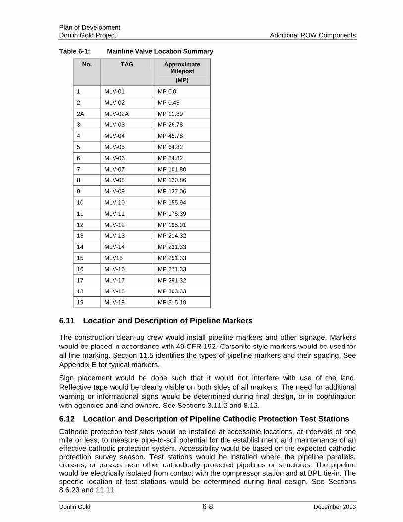
Plan of Development Donlin Gold Project Additional ROW Components
Donlin Gold 6-8 December 2013
Table 6-1: Mainline Valve Location Summary
No. TAG Approximate Milepost
(MP)
1 MLV-01 MP 0.0
2 MLV-02 MP 0.43
2A MLV-02A MP 11.89
3 MLV-03 MP 26.78
4 MLV-04 MP 45.78
5 MLV-05 MP 64.82
6 MLV-06 MP 84.82
7 MLV-07 MP 101.80
8 MLV-08 MP 120.86
9 MLV-09 MP 137.06
10 MLV-10 MP 155.94
11 MLV-11 MP 175.39
12 MLV-12 MP 195.01
13 MLV-13 MP 214.32
14 MLV-14 MP 231.33
15 MLV15 MP 251.33
16 MLV-16 MP 271.33
17 MLV-17 MP 291.32
18 MLV-18 MP 303.33
19 MLV-19 MP 315.19
6.11 Location and Description of Pipeline Markers
The construction clean-up crew would install pipeline markers and other signage. Markers would be placed in accordance with 49 CFR 192. Carsonite style markers would be used for all line marking. Section 11.5 identifies the types of pipeline markers and their spacing. See Appendix E for typical markers.
Sign placement would be done such that it would not interfere with use of the land. Reflective tape would be clearly visible on both sides of all markers. The need for additional warning or informational signs would be determined during final design, or in coordination with agencies and land owners. See Sections 3.11.2 and 8.12.
6.12 Location and Description of Pipeline Cathodic Protection Test Stations Cathodic protection test sites would be installed at accessible locations, at intervals of one mile or less, to measure pipe-to-soil potential for the establishment and maintenance of an effective cathodic protection system. Accessibility would be based on the expected cathodic protection survey season. Test stations would be installed where the pipeline parallels, crosses, or passes near other cathodically protected pipelines or structures. The pipeline would be electrically isolated from contact with the compressor station and at BPL tie-in. The specific location of test stations would be determined during final design. See Sections 8.6.23 and 11.11.

Plan of Development Donlin Gold Project Government Agency Involvement
Donlin Gold 7-1 December 2013
7.0 Government Agency Involvement 7.1 Entities that have Regulatory Authority or would be affected by the
Proposed Project Specific federal, state, and local government agencies have regulatory authority over different aspects of the pipeline project. The scope of regulatory decision-making includes the authorities listed in Table 7-1.
Table 7-1: Federal, State and Local Agencies with Regulatory Authority
Federal Agencies U.S. Department of the Interior–Bureau of Land Management U.S. Army Corps of Engineers U.S. Coast Guard U.S. Environmental Protection Agency U.S. Department of Transportation
• Pipeline and Hazardous Materials Safety Administration Office of Pipeline Safety
U.S. Fish and Wildlife Service National Marine Fisheries Service Federal Aviation Administration State Agencies Alaska Department of Natural Resources
• State Pipeline Coordinator Office
• Office of History and Archaeology • Division of Forestry
• Division of Mining, Land and Water Alaska Department of Environmental Conservation Alaska Department of Fish and Game Alaska Department of Health and Social Services Alaska Department of Labor and Workforce Development Alaska Department of Public Safety-Fire Marshall Alaska Department of Transportation and Public Facilities Local Agencies Matanuska-Susitna Borough Kenai Peninsula Borough
There are also a number of federally recognized tribes along the proposed pipeline route with whom government-to-government consultation may be required during the NEPA process. (Table 7-2)

Plan of Development Donlin Gold Project Government Agency Involvement
Donlin Gold 7-2 December 2013
Table 7-2: Federally Recognized Tribes along the Pipeline Route by Region
Region Community BIA Recognized Tribe
Southwest Alaska- Kuskokwim River
Crooked Creek Village of Crooked Creek
Georgetown Native Village of Georgetown
Red Devil Village of Red Devil
Sleetmute Village of Sleetmute
Stony River Village of Stony River
Southwest Alaska- Yukon-Kuskokwim Delta
Lime Village Lime Village
South central Alaska Knik Knik Tribe
Tyonek Native Village of Tyonek
Interior Alaska McGrath McGrath Native Village
Nikolai Nikolai Village
Shageluk Shageluk Native Village
Takotna Takotna Village
Telida Telida Village
Anvik Anvik Village
Grayling Organized Village of Grayling (aka Holikachuk)
Holy Cross Holy Cross Village
7.2 Communications Protocol
7.2.1 State Agency Coordination The SPCO has established a set protocol for coordinating communications involving projects that are within the State Pipeline Coordinator’s authority. Figure 7-1 graphically depicts the flow of communication to and from the SPCO for state agency coordination.
7.2.2 Federal Agency Coordination The BLM would be the federal agency responsible for the pipeline grant of ROW and associated temporary use permits on federal lands and the USACE would be the lead agency for the NEPA process with federal agencies such as USEPA, USFWS, PHMSA and others participating as cooperating agencies. Donlin Gold would seek other specific authorizations needed from agencies other than BLM.

COMMUNICATION PROTOCAL FOR STATE AGENCY
COORDINATION
FIGURE:SCALE:
DG: PER0279.mxd, 08/30/11, R01DONLIN GOLD PROJECT
7-1NA

Plan of Development Donlin Gold Project Government Agency Involvement
Donlin Gold 7-4 December 2013
7.3 List of Project Authorizations A substantial effort would be required to obtain all necessary project authorizations for beginning construction activities. These authorizations are identified in Table 7-3 and organized by subject. No Federal Energy Regulatory Commission (FERC) Section 7(c) application is required because the proposed action is intrastate and, therefore, outside FERC jurisdiction.
7.3.1 State ROW Lease Required Documents Figure 7-2 identifies the following categories of documents: those that are required once the State ROW Lease is issued and before the SPCO would accept an application for an overall Notice to Proceed (NTP) with the project on state land under the ROW Lease: documents required once the overall NTP is received but before an application would be accepted for an NTP for a specific construction segment; documents required to be submitted with an application for an NTP for a specific construction segment; documents that are required to be submitted before actual startup; and documents that would be required annually following startup required on an as-needed basis during operation and required at the end of life of the project. The SPCO may request documents under the terms and conditions of the lease or authority that may not be listed in this chart.

STATE ROW LEASE REQUIRED DOCUMENTS
FIGURE:SCALE:
DG: PER0281.mxd, 08/30/11, R01DONLIN GOLD PROJECT
7-2NA
Source: Alaska Gas Development Authority

Plan of Development Donlin Gold Project Government Agency Involvement
Donlin Gold 7-6 December 2013
Table 7-3: Permits and Authorizations
Permit Type Agency Citation Activity Acquisition
Time Notes
Land Use
Federal pipeline grant of ROW and associated temporary use permits
BLM 43 CFR 2880, and the Mineral Leasing Act of 1920; 43 CFR 2800 and the Federal Lands Policy and Management Act
ROW for new pipeline through federal lands. 3 years
Submittal of SF 299 application(s)for ROW(s) initiates the BLM's NEPA process
State pipeline ROW lease ADNR SPCO
AS 38.35 11 AAC 80.005
Pipeline ROW lease for a new pipeline on state lands. 3years .
Federal grant of ROW for fiber optic cable
BLM 43 CFR 2800 and the Federal Lands Policy and Management Act
ROW for new fiber optic cable through federal lands
State ROW for fiber optic cable ADNR DMLW AS 38.05 ROW for a new fiber optic cable through state lands
Discharge into Waters of the US
Preliminary jurisdictional determination
USACE 33 CFR 331.2 To determine the presence of wetlands (waters of the U.S.). 90 days after submittal of Jurisdictional Determination
A Final Jurisdictional Determination is issued after the selected Alternate is identified in the ROD.
Dredged or fill material USACE 33 CFR 323 (Section 404 of CWA) Placement of fill or dredged material into waters of the U.S. (wetlands). 3 years
Submittal of USACE permit application initiates the USACE's NEPA process.
Dredged or fill material ADEC 18 AAC 70 (Section 401 of CWA) Water Quality Certification for a permit for placement of fill or dredged material into waters of the U.S. (wetlands). 3 years
Section 401 would be obtained concurrent with the Section 404 permit.
Permit Applications To Be Submitted During EIS Process
Navigable Waters and Water Use
Permits For Structures or Work In or Affecting Navigable Waters of The United States
USACE 33 CFR 322 (Section 10 of the Rivers and Harbors Act of 1899)
Authorization for certain structures or work in or affecting navigable waters of the United States, including docks, wharf, piers and other structures.
3 years Included in Section 404 permit application
Construction of dams/ dikes or bridges/causeways in navigable waters
U.S. Coast Guard 33 CFR, Subchapter J Section 9 of the Rivers and Harbors Act of 1899; General Bridge Act of 1946
Construction of any dam or dike in a navigable river or navigable water of the U.S. must be permitted by USACE. Construction of any bridge or causeway in a navigable river or navigable water of the U.S. must be permitted by USDOT.
3 years Included in Section 404 permit application
State Navigable Waters Determination
ADNR AS 38.05.127 State would make navigable waters determination. Concurrent with state pipeline ROW lease processing.
Wildlife
Fish passage and habitat protection ADF&G AS 16.05.871 (Habitat) AS 16.05.841 (Passage)
Permit is necessary for activities that use, divert, obstruct, pollute, or change natural flow of specified anadromous fish streams. Permit is necessary for activities that use, divert, obstruct, pollute, or change natural flow of non- anadromous fish streams that have resident fish.
90 days
Bald and golden eagles USFWS 50 CFR 22 Bald and Golden Eagle Protection Act
Any activity that could "take" a bald or golden eagle, their eggs, feathers or nest as defined within the Eagle Protection Act.
N/A Not a permit - consultation required
Migratory birds USFWS 50 CFR 21 Migratory Bird Treaty Act Project activities that require consultation regarding effects to migratory bird species. N/A Not a permit - consultation required

Plan of Development Donlin Gold Project Government Agency Involvement
Donlin Gold 7-7 December 2013
Wildlife protection measures ADF&G 5 AAC 95.900 Design and construction of pipeline to avoid significant alteration of caribou and other large ungulate movement and migration patterns.
N/A Not a permit - consultation required under NEPA State ROW Lease would require a Wildlife Interaction Plan
Table 7-3 (Continued): Permits and Authorizations
Permit Type Agency Citation Activity Acquisition
Time Notes
Endangered, Threatened, or Candidate Species
USFWS 50 CFR 402 Section 7 of the ESA If proposed activity affects species listed under the ESA, obtain agreement with USFWS about scope of studies to determine project's probable effect on Threatened and Endangered Species.
N/A Not a permit - consultation required under ESA.
Essential Fish Habitat (EFH) NMFS 50 CFR 600 Magnuson-Stevens Act provisions
Federal agencies are required to consult with NMFS on any action that may result in adverse effects to EFH. N/A Not a permit - consultation required under NEPA
Fish collection ADF&G AS 16.05.340(b) Required of anyone who wants to collect or hold alive any live fish, shellfish, or aquatic plants or their gametes (except gold fish and decorative tropical fish) for purposes of science, education, propagation, or exhibition
30 days Typically required for field studies
Archaeological
Archeological Resources Protection Act Permit (ARPAP)
BLM 16 USC 470; activities that require cultural resource surveys on federal land.
Activities that require cultural resource surveys on federal land. 30 days
Alaska cultural resource ADNR/SHPO AS 41.35.080 Permit is required for investigation, excavation, gathering, or removal of any historic, prehistoric, or archaeological resources of the state.
30 days Typically required for field studies only
Section 106 consultation USACE/ ADNR/SHPO/ Tribes/ACHP
36 CFR Part 800, National Historic Preservation Act (NHPA)
Any project funded, licensed, permitted, or assisted by the federal or state government. The USACE as the lead federal agency that enforces compliance with this law for this project is also required to consult with other agencies, tribes, the SHPO, and the Advisory Council on Historic Preservation (ACHP).
N/A Not a permit - consultation required under NEPA
Preservation of historic, prehistoric, and archaeological resources
ADNR/SHPO AS 41.35.070 (OHA), SHPO, Alaska Historic Preservation Act
Any project located on state lands. 90 days Concurrence required from OHA and SHPO
Land Use
Casual and temporary use permits BLM 43 USC 1701(FLPMA); Mineral Leasing Act of 1920 Section 28 43 CFR 2920
Project Activities that would require access to or for temporary use of federal lands.
Special area permit ADF&G ADNR
5 AAC 95.420, 5 AAC 95.700-770 Activities, except for lawful hunting, trapping, fishing, viewing, and photography occurring in state game refuges, sanctuaries, critical habitats, state recreation areas, across designated wild and scenic rivers, or through state parks require a special area permit. Use of helicopter or motorized vehicle requires a permit.
90 days
Land use and/or zoning MSB MSB Comprehensive Plans and Zoning
Activities occurring within MSB and on MSB lands. 60 days
Land use and/or zoning KPB KPB Comprehensive Plans and Zoning
Activities occurring within KPB and on KPB lands. 60 days
Coastal Zone management Program not applicable at time document was prepared
Miscellaneous - Consultations, Stipulations, and Requirements
Environmental justice All federal agencies Executive Order (EO) 12898 Activities that may disproportionately affect minorities and low-income populations (for example, subsistence). N/A Not a permit - consultation required under NEPA
Protection of Subsistence Users and Resources
State and Federal AS 38.35.100 Mitigate impacts to users and resources N/A
Health Impact Assessment DHSS Not a State statutory requirement- associated with EIS
Assess potential impacts of the project on health in the general area N/A Not a permit
Wetlands protection consideration All federal agencies Executive Order (EO) 11990 Agencies must take action to minimize the destruction, loss, or degradation of wetlands. N/A Not a permit - consultation required under NEPA

Plan of Development Donlin Gold Project Government Agency Involvement
Donlin Gold 7-8 December 2013
Table 7-3 (Continued): Permits and Authorizations
Permit Type Agency Citation Activity Acquisition
Time Notes
Preconstruction, Construction, and Operation Permits
Water Use
Floodplain management All federal agencies Executive Order (EO) 11988 Agencies must take action to reduce the risk to flood loss; minimize the impact of floods on human safety, health, and welfare; and restore and preserve the beneficial effects served by floodplains.
Not a permit - consultation required under NEPA
Permit to appropriate water ADNR 11 AAC 93.040 - 140 Application for water for camp use.
Temporary water use ADNR 11 AAC 93.220 Temporary water use, ice armoring, and pipe testing for period of less than 5 consecutive years.
Fish habitat protection ADF&G AS 16.05.871 or AS 16.05.841 Water withdrawal from fish bearing waterbodies.
APDES Construction Stormwater Permit
ADEC 18 AAC 83 Discharge of pollutant from a point source into waters of the U.S. Alaska is fully authorized to administer the EPA's NPDES program. 18 AAC 83.990 implements the Alaska Pollutant Discharge Elimination System (APDES) point source wastewater discharge program in a manner that meets the purposes of AS 46.03 and in accordance with 33 U.S.C. 1342 (Clean Water Act, sec. 402) and the requirements adopted by reference at 18 AAC 83.010.
Non-domestic wastewater disposal ADEC 18 AAC72.500-.900 Discharges to land, surface water, or groundwater in Alaska.
Hazardous Material and Waste
Approval from local landfill operators to deposit non-hazardous solid waste
MSB MSB regulations Handling of solid waste at local landfills.
Generator ID number USEPA 40 CFR 262, RCRA, (18 AAC 62.210 adopted by reference)
All companies that treat, store, dispose of, transport, or offer for transport regulated waste must obtain an EPA ID number.
Transportation and disposal of hazardous waste
USEPA 40 CFR 262, RCRA (18 AAC 62.210 adopted by reference)
Follow requirements regarding transportation, treatment, and disposal of hazardous waste.
Hazardous chemical inventories USEPA 40 CFR 302, CERCLA, Title III Superfund Amendments and Reauthorization Act
Reporting, planning requirements for facilities that handle, store, and/or manufacture hazardous materials.
Hazardous chemical inventories Alaska Department of Military Affairs
AS 26.23.073, AS 26.23.077 Reporting, planning requirements for facilities that handle, store, and/or manufacture hazardous materials.
Wildlife
Public safety ADF&G 5 AAC 92.033 Permit to take, relocate, haze, or destroy birds or their eggs or nests, mammals or reptiles for public safety purposes.
Air Quality
Air quality requirements for open burning (vegetation from ROW)
ADEC 18 AAC 50.065 (b)-(f) General requirements for open burning, also requires that (1) material is kept dry, (2) noncombustibles are separated, (3) draft is present, (4) combustibles are separated from grass and peat, and (5) combustibles are not allowed to smolder.
Transportation
Transportation of hazardous materials
ADOT&PF 17 AAC 25.200 Transportation of hazardous materials, hazardous substances, or hazardous waste by vehicle.
Airport operation Federal Aviation Administration
14CFR139 An Airport Operating Certificate must be obtained to construct, align a new airport, or activate an airport. This permit may not be applicable for proposed activities
Table 7-3 (Continued): Permits and Authorizations

Plan of Development Donlin Gold Project Government Agency Involvement
Donlin Gold 7-9 December 2013
Permit Type Agency Citation Activity Acquisition
Time Notes
Oversized and overweight vehicles (pipe hauling)
ADOT&PF 17 AAC 25.300 Oversize and overweight vehicle permit.
Camp
Domestic wastewater discharge permit and plan approval
ADEC 18 AAC 72 11 AAC 83
Permit and plan approval required before domestic wastewater system can be constructed, installed, operated.
Domestic wastewater discharge permit and plan approval
ADEC 18 AAC 72.010, 200, and 215 Permit and plan approval required before domestic wastewater system can be constructed, installed, operated.
Drinking water plan approval ADEC 18 AAC 80.200 Camps—human consumption.
Food service (camps) ADEC 18 AAC 31.020 Permit for food service facilities serving 10 or more people per day.
Solid waste management ADEC 18 AAC 60 Handling of solid waste at camp locations and final disposition.
Miscellaneous
SPCC USEPA 40 CFR 112 Oil Pollution Prevention SPCC must be available for review. Discharge of oil from non-transportation-related onshore facilities onto or upon navigable waters of the U.S. Includes ancillary oil storage, including natural gas condensate, and oil-filled equipment such as compressors at interstate and intrastate onshore natural gas pipeline systems.
Natural gas pipeline safety Pipeline and Hazardous Materials Safety Administration
49 CFR 190-192 Transportation of Natural Gas by Pipeline Safety and Reporting Requirements.
OSHA Regulations ADOL/WD AS 18.60.180, 8 AAC Assurance that project related activities meet standards and regulations for occupational health and safety.
Fire Marshall Permit ADPS AS 18.70.080, 13 AAC 50.027 Permit and plan approval by State Fire Marshal for construction of facilities
Mineral Material Sales Contract BLM Mineral Leasing Act and other applicable laws 43 CFR 3600
Use of gravel, sand and/or rock from sources on federal land.
Material Sale Contract ADNR AS 38.05 Use of gravel, sand and/or rock from sources on state land.
Land Use Permit ADNR AS 38.05 Land Use Permit is required for any material batch or processing plant on State land
Fuel Systems ADPS 2009 IFC All fuel systems being developed to support port and airport operations during pipeline construction and operations must be reviewed and found to conform with the 2009 International Fire Code (IFC) requirements.
Explosive Storage ADPS 2009 IFC Although explosive blasting is not anticipated to be used in the project, if used the storage magazine type, location and any barricade requirements must meet IFC requirements.
Transport of Explosives Permit and License
U.S.BATF If explosives are used in the project it would require a permit and license from the U.S. Bureau of Alcohol, Tobacco, and Firearms for use and transport.
Letters of Non-objection/Agreement ADNR/Permittee Letters of non-objection or agreements from ENSTAR Natural Gas Company (ENSTAR), CEA and GCI for the tie-ins to existing authorized facilities will be required (Note: Final authorization for the ENSTAR Beluga Line has not been issued).
Concurrence ADOT&PF/ADNR/SHPO Concurrence needed for segments of project that potentially affect the Iditarod National Historical Trail.
Right-of-Way ADNR/BLM/ private land owners
Authorizations/agreement to install fiber optic cable and construct repeater station
ADOT&PF/ FAA DOTPF/FAA concurrence would be required at public airstrips
Conditional Use Permit for Earth materials Extraction Activities
Mat Su Borough MSB 17.30 An administrative permit, under MSB 17.30 – Conditional Use Permit for Earth Materials Extraction Activities
Material Site Permit Kenai Peninsula Borough KPB 21.26 A conditional land use permit is required before extraction or operation of a material site (if any used from locations in Kenai Peninsula Borough)

Plan of Development Donlin Gold Project Government Agency Involvement
Donlin Gold 7-10 December 2013
Notes: ADEC = Alaska Department of Environmental Conservation KPB = Kenai Peninsula Borough ADF&G = Alaska Department of Fish and Game LOA = Letter of Authorization ADNR = Alaska Department of Natural Resources ADOLWD = Alaska Department of Labor and Workforce Development ODPCP = Oil Discharge Prevention and Contingency Plan ADOT& PF = Alaska Department of Transportation and Public Facilities ADPS = Alaska Department of Public Safety MMPA = Marine Mammal Protection Act APDES = Alaska Pollutant Discharge Elimination System MSB = Matanuska-Susitna Borough AS = Alaska Statute N/A = not applicable BLM = U.S. Department of Interior, Bureau of Land Management NEPA = National Environmental Policy Act CERCLA = Comprehensive Environmental Response, Compensation, and Liability Act of 1980 NHPA = National Historic Preservation Act CFR = Code of Federal Regulations NMFS = National Marine Fisheries Service CWA = Clean Water Act OHA = Alaska Office of History and Archaeology USDOT = U.S. Department of Transportation RCRA = Resource Conservation and Recovery Act EFH = Essential Fish Habitat ROD = record of decision EIS = environmental impact statement ROW = right-of-way EO = Executive Order SHPO = State Historic Preservation Office USEPA = U.S. Environmental Protection Agency SPCC = spill prevention control and countermeasure plan ESA = Endangered Species Act USACE = U.S. Army Corps of Engineers ID = identification USFWS = U.S. Fish and Wildlife Service

Plan of Development Donlin Gold Project Construction of Facilities
Donlin Gold 8-1 December 2013
8.0 Construction of Facilities 8.1 Construction Planning Considerations
8.1.1 Iditarod Trail The Iditarod Trail consists of a main trail approximately 938 miles (1,510 km) in length and numerous connecting trails. The main trail originally connected the ice-free port of Seward with the mining and trade center of Nome, an ice-locked port from October to June. The Iditarod and its connecting trails, which were and remain primarily winter trails, provided access to three major Alaska mining regions – the Cook Inlet Country, the Inland Empire (between Iditarod and Ruby), and the Seward Peninsula. The Iditarod Trail was named after the Interior gold rush settlement and mining district of the same name that was accessed by the Trail (BLM 1986 Comprehensive Management Plan (CMP)).
Between 1908, when the U.S. Army’s Alaska Road Commission blazed the main trail, and the 1930’s, the Iditarod Trail served as one of three main cross-Alaska routes. The decline of mining after World War I and the introduction of the airplane for mail and freight service caused a decrease of trail use (BLM 1986 CMP).
The INHT was established in 1978 when the National Trails System Act of 1968 was amended to include National Historic Trails. The term “Iditarod” is now principally associated with the Iditarod Sled Dog Race, which completed its first run to Nome in 1973. Other sled dog, snowmachine and human-powered endurance races also take place today on portions of the Iditarod Trail. These races include: the Northern Lights 300, Knik 200 and Junior Iditarod sled dog races; the Iron Dog snowmachine race which began in 1984; and the Iditarod Invitational whose participants include nordic skiers, mountain bikers, snowshoers and runners and is a successor race to the former Iditaski race which began in 1984 and was followed by the Iditabike and Iditasport events (BLM 1986 CMP, Iditarod and Iditarod Invitational websites). While these race events take place on the Iditarod Trail, not all of them occur on the sections of the Iditarod Trail that are crossed by the proposed pipeline.
In addition to the formal race events described above, the Iditarod Trail serves as local access for commercial lodges, remote cabins and properties, hunters and general recreation.
The proposed Donlin Gold pipeline route would intermittently intersect the Iditarod Trail on State land between a crossing at MP 50.59, which is located approximately two miles northeast of the confluence of the Skwentna and Talachulitna Rivers, and a final crossing at MP 148.21, which is approximately two miles west of the South Fork of the Kuskokwim River. The proposed pipeline route would cross the INHT, the State’s Public Access Easements for the Iditarod Trail and the Susitna-Rainy Pass and Rainy Pass-Big River Trails, which are RS 2477 ROWs, at the intersection points described in Table 8-1 below.
The proposed pipeline route would not cross or coincide with the INHT on federal, Native Corporation-owned or other private land.
Three 400 ft (122 m) wide State Public Access Easements exist on State land for the Iditarod Trail along the proposed pipeline route. These are ADL 222930, (Susitna to Rainy Pass); ADL 230122 (Rainy Pass to Rohn) and ADL 230363 (Rohn to Takotna).

Plan of Development Donlin Gold Project Construction of Facilities
Donlin Gold 8-2 December 2013
An Iditarod Trail Location Survey, ASLS 69-73, was performed by Bomhoff & Associates, Inc. in 1981 and recorded in 1982 (Anchorage Recording District, Plat 82-42, March 5, 1982) describing the section of Trail from Susitna Station to Finger Lake. The Susitna to Rainy Pass (Finger Lake) section of ADL 222930 is described by ASLS 69-73. The survey plat for ASLS 69-73 contains certificates from the Iditarod Trail Committee and “Iditarod Trail Blazer” Joe Reddington Sr., certifying that the survey plat is an accurate depiction of the Historic Iditarod Trail.
There are also two 100 ft wide (30.5 m) RS 2477 ROWs on State Land along the proposed pipeline route between MP 50.59 and MP 148.21: RST 199, the Susitna-Rainy Pass Trail and RST 174, the Rainy Pass-Big River Trail.
The sections of the Iditarod Trail and non-section line RS 2477 ROWs that are crossed by the proposed pipeline between MP 50.59 and MP 148.21 are described in Table 8-1 and depicted in Appendix A on strip maps numbered 8, 9 and 12 of 23.
Management of the Iditarod Trail on State Land In 1988, the state entered into a Memorandum of Agreement (MOA) with the BLM concerning the INHT. In the MOA, the State agreed to manage the INHT system located on State lands “according to the laws, regulations, and policies directing each state…agency….” and “in a manner which protects and interprets historic values.” Under the MOA, the 1986 INHT CMP is the common guide to be utilized for managing the INHT. However, “Nothing in (the MOA) shall affect or interfere with the fulfillment of the obligations and rights of the parties to manage the lands and programs administered by them in accordance with their other land management responsibilities.” The State consults the CMP as a guide for managing the historic values of the INHT to the extent agreed to in the MOA. However, the State has its own land planning and management processes that arise from State laws, regulations and policies.
Mitigation Measures for consideration Mitigation measures would be identified and evaluated through the permitting process in consultation with stakeholders and the appropriate agencies.
Physical mitigation measures may include co-location of the proposed pipeline with the Iditarod Trail where appropriate to reduce multiple crossings of the Trail by the pipeline and thereby reduce the possibility that the pipeline ROW may become used as a separate trail.
Appropriate signage that clearly distinguishes the Trail from the pipeline ROW at points where the pipeline crosses the Trail can serve to guide Trail users to stay on the Trail and off of the pipeline ROW where the two are not co-located. Another possibility would be to revegetate, or otherwise block access to, a narrow strip of the pipeline ROW where it crosses the Trail to help steer and keep Trail users on the Trail.
Today, nonprofits, agencies and communities work together on trail projects to mark, brush and improve segments of the Trail. They also work together to construct and manage shelter cabins. Portions of the Iditarod Trail are used throughout the winter by communities as a transportation route. Some segments of the Trail are not marked and are overgrown with brush and in need of trail work to improve travel safety. Donlin Gold will work with the Iditarod Historic Trail Alliance and other user groups to promote Trail preservation and use.
Any actual mitigation measures for impacts to the INHT would be agreed to as a part of the Section 106 compliance process and outlined in a Programmatic Agreement.

Plan of Development Donlin Gold Project Construction of Facilities
Donlin Gold 8-3 December 2013
Table 8-1: Pipeline Crossings of INHT, State of Alaska Public Access Easements for the Iditarod Trail and non-section line RS 2477 Rights-of-Way
Milepost From
Milepost To Description Case ID Map ID
50.59 50.68 Iditarod National Historic Trail
MAP-05
50.59 50.68 State Public Access Easement for Iditarod Trail, 400 ft wide, Susitna to Rainy Pass ADL 222930 MAP-05
51.64 51.73 Iditarod National Historic Trail
MAP-05
51.64 51.73 State Public Access Easement for Iditarod Trail, 400 ft wide, Susitna to Rainy Pass ADL 222930 MAP-05
57.87
Susitna-Rainy Pass Trail RST 199 MAP-06
62.76
Susitna-Rainy Pass Trail RST 199 MAP-06
66.93
Susitna-Rainy Pass Trail RST 199 MAP-06
75.47
Susitna-Rainy Pass Trail RST 199 MAP-07
78.81
Susitna-Rainy Pass Trail RST 199 MAP-07
81.19
Susitna-Rainy Pass Trail RST 199 MAP-07
81.80
Susitna-Rainy Pass Trail RST 199 MAP-07
85.83 86.00 Iditarod National Historic Trail
MAP-08
85.83 86.00 State Public Access Easement for Iditarod Trail, 400 ft wide, Susitna to Rainy Pass ADL 222930 MAP-08
86.28 86.28 Susitna-Rainy Pass Trail RST 199 MAP-08
86.49 86.95 Iditarod National Historic Trail
MAP-08
86.49 86.95 State Public Access Easement for Iditarod Trail, 400 ft wide, Susitna to Rainy Pass ADL 222930 MAP-08
86.77 86.77 Susitna-Rainy Pass Trail RST 199 MAP-08
87.12 87.20 Iditarod National Historic Trail
MAP-08
87.12 87.20 State Public Access Easement for Iditarod Trail, 400 ft wide, Susitna to Rainy Pass ADL 222930 MAP-08
90.41 90.66 Iditarod National Historic Trail
MAP-08
90.41 90.66 State Public Access Easement for Iditarod Trail, 400 ft wide, Susitna to Rainy Pass ADL 222930 MAP-08
90.91 90.91 Susitna-Rainy Pass Trail RST 199 MAP-08
90.94 91.10 Iditarod National Historic Trail
MAP-08
90.94 91.10 State Public Access Easement for Iditarod Trail, 400 ft wide, Susitna to Rainy Pass ADL 222930 MAP-08
91.23 93.35 Iditarod National Historic Trail
MAP-08
91.23 93.35 State Public Access Easement for Iditarod Trail, 400 ft wide, Susitna to Rainy Pass ADL 222930 MAP-08
91.38 91.38 Susitna-Rainy Pass Trail RST 199 MAP-08
91.52 91.52 Susitna-Rainy Pass Trail RST 199 MAP-08
93.70 93.70 Susitna-Rainy Pass Trail RST 199 MAP-08
95.11 95.29 Iditarod National Historic Trail
MAP-08
95.11 95.29 State Public Access Easement for Iditarod Trail, 400 ft wide, Susitna to Rainy Pass ADL 222930 MAP-08
96.00 96.13 Iditarod National Historic Trail
MAP-08

Plan of Development Donlin Gold Project Construction of Facilities
Donlin Gold 8-4 December 2013
Milepost From
Milepost To Description Case ID Map ID
96.00 96.13 State Public Access Easement for Iditarod Trail, 400 ft wide, Susitna to Rainy Pass ADL 222930 MAP-08
97.02 97.10 Iditarod National Historic Trail
MAP-08
97.02 97.10 State Public Access Easement for Iditarod Trail, 400 ft wide, Susitna to Rainy Pass ADL 222930 MAP-08
97.08 97.08 Susitna-Rainy Pass Trail RST 199 MAP-08
100.83 100.91 State Public Access Easement for Iditarod Trail, 400 ft wide, Susitna to Rainy Pass ADL 222930 MAP-09
101.06 101.42 Iditarod National Historic Trail
MAP-09
101.06 101.42 State Public Access Easement for Iditarod Trail, 400 ft wide, Susitna to Rainy Pass ADL 222930 MAP-09
101.12 101.12 Susitna-Rainy Pass Trail RST 199 MAP-09
104.89 105.75 Iditarod National Historic Trail
MAP-09
104.89 105.75 State Public Access Easement for Iditarod Trail, 400 ft wide, Rainy Pass to Rohn ADL 230122 MAP-09
146.72 146.72 Iditarod National Historic Trail over State-Owned navigable water MAP-12
147.30 147.38 Iditarod National Historic Trail
MAP-12
147.34 147.34 Rainy Pass-Big River Trail RST 174 MAP-12
148.21 148.29 State Public Access Easement for Iditarod Trail, 400 ft wide, Rohn to Takotna ADL 230363 MAP-12
8.1.2 Remote Cabins/Residential Areas The proposed pipeline would be constructed in very remote locations, and there would be relatively little construction near residential areas as shown in the land status information provided in Appendix A. There are scattered homesites and homesteads between approximately MP 55 and MP 94, but the proposed pipeline ROW would not encroach on any of this private property. In developing the proposed pipeline preferred alignment Donlin Gold has avoided non-ANCSA corporation, privately owned parcels. In addition, where future land disposals were identified, efforts were made to avoid or reduce any impact on those areas. Onestone Lake Subdivision, Shell Hills Subdivision, Happy Valley Remote Recreation Cabin Staking Area, Porcupine Butte Remote Recreation Cabin Staking Area and other land status information and authorizations in proximity to the pipeline ROW are shown in Appendix A.
There are also a number of state and federal authorized temporary base and spike camps operated by guide-outfitter camps located in the vicinity of the proposed pipeline route, which may change annually.
8.1.3 Active Faults There are two active faults that the pipeline route crosses that have been identified. These are the Denali-Farewell Fault between approximately MP 148.4 and 148.7 and the Castle Mountain Fault between approximately MP 7.4 and 7.7. During any future event on these faults, permanent ground displacement from fault movement is expected to be primarily horizontal rather than vertical. After considering the information regarding these faults, the engineering design for the crossing of these two active faults would place the pipeline aboveground. Each of the two crossing sections would be approximately 1,400 ft (426.7 m)

Plan of Development Donlin Gold Project Construction of Facilities
Donlin Gold 8-5 December 2013
in length at the locations shown in Appendix A, see Section 8.6.18 for more detailed information.
8.1.4 Wetlands and Waterbodies In routing the pipeline, stream crossings and wetlands areas were avoided to the extent possible. Design and construction methods were also modified to avoid or reduce wetland impacts where practical and include methods such as constructing the portions of the pipeline in low-lying areas during winter months when the ground is frozen and protected by snow cover.
Construction effects on fish and fish habitat areas would be minimized by selection of stream crossing techniques that provide the appropriate level of protection for the specific habitat sensitivity. In-water work windows can be used to minimize effects on fishery resources during sensitive life-cycle stages. The use of appropriate streambank rehabilitation and reclamation techniques and BMPs would prevent long term effects on fish and fish habitats within the project area.
Pipeline crossings of watercourses would be achieved by buried methods. The method selected would depend on the season of crossing, terrain, and geotechnical and environmental conditions. Typical engineering drawings for these methods are provided in Appendix E. Each stream crossing would be conducted in a manner and during a time period that avoids or minimizes potential fishery effects. HDD crossings were determined based on the following:
1) Is this a significant sized river that presents engineering/other challenges for trenching?
2) What is the technical feasibility of drilling, can it be done with current technology? 3) Is there significant traffic on the river? 4) What is the proposed season for construction and trenching (if not drilled), summer
or winter? 5) Is this a river that has environmental or engineering considerations that would
mandate evaluating the use of HDD? 6) What are the environmental, engineering, schedule and cost impacts associated with
HDD at the crossing?
Pipeline stream crossings would be accomplished using one of the following or similar crossing methods: HDD, open-cut dry flume, open-cut dam and pump, flowing water open-cut, non-flowing water open-cut, or small creek crossing. Typical winter crossings of water courses where there is no surface flow would be by open cut. Where feasible, the crossing would be open-cut; otherwise, the crossing would be achieved by HDD based on the above evaluation criteria. Smaller drainages would be installed by open-cut, where practical. Section 8.6.15 presents a detailed discussion regarding water body crossings. Appendix E shows typical water crossing methods.
Bore depth for HDD would be determined based on environmental and geotechnical information provided in Appendix C and Appendix D. Appendix E also provides typical stream crossing bridge drawings illustrating bridges that would be employed during construction. Use of such crossings would be determined based on the stream, presence of fish resources, and engineering factors.

Plan of Development Donlin Gold Project Construction of Facilities
Donlin Gold 8-6 December 2013
Water withdrawal from lakes and streams for HDD, ice road construction or for hydrostatic testing would be planned and executed in accordance with the requirements of the appropriate permits and authorizations. See Section 8.4.7 for information regarding water uses and potential sources.
HDD operations would be addressed in the HDD Plan which would be prepared to meet regulatory requirements including management and disposal of drill cuttings and drill mud generated as a result of HDD operations.
8.1.5 Access and Existing Roads and Trails Through its Public Outreach Donlin Gold would provide information to the general public regarding pipeline construction activities and how to coordinate access needs with construction activities. In areas where construction activities would affect existing access routes Donlin Gold would provide alternate access or allow for controlled access within or across the construction area as needed. This would include ADL 222930/RST-199, the main transportation route in the region, Section 17(b) easements and other currently used trails. Sections 3.11.2, 9.1, and 10.8 contain more information.
The BLM would retain discretion on access to that portion of the ROW within federal public lands.
The Iditarod Trail serves as the primary land route for access from the east side of the Alaska Range to the hunting grounds for a March bison hunt and other purposes. During construction there would be temporary impacts to this access route. However, these impacts would be addressed by providing alternative or controlled access along the construction ROW to minimize impacts and accommodate travelers to the extent reasonably possible. Impacts to other existing trails, section line easements and any other authorized access route should be minimal, as access across the ROW would remain following construction and accommodated during the construction of the pipeline. See Section 8.1.1 for Iditarod discussion.
Possible section line easements exist where the alignment crosses State land in the vicinity of the Jones River; these are subject to verification by ADNR.
8.1.6 Susitna Flats State Game Refuge The proposed pipeline route would begin at a tie-in with the existing BPL in the SFSGR and run north through the refuge following the existing 100 ft (30 m) wide all-season gravel Pretty Creek Road. Approximately 50 ft (15 m) of the Pretty Creek ROW width has already been cleared to accommodate the road. The remaining forest and shrubland for the authorized pipeline construction corridor would be cleared to allow for pipeline installation. The Pretty Creek Alternate would cross approximately 5.1 miles (8.2 km) of the SFSGR.
The proposed electric transmission line would parallel the existing Chugach Electric power transmission lines in the SFSGR to provide power to the metering station at MP 0, the start of the pipeline. From the metering station the aerial power transmission line would go on to the compressor station at approximately MP 0.4 also within the SFSGR near the tie-in to the BPL. Although Donlin Gold has not determined where the fiber optic communications cable would originate, if it is from a location in Beluga, the fiber optic cable may also use the transmission line support structures to the metering station. From the metering station, the fiber optic cable would be buried in the pipeline ROW to the compressor station and on to the Donlin Gold mine site.

Plan of Development Donlin Gold Project Construction of Facilities
Donlin Gold 8-7 December 2013
8.1.7 Construction Communications and Public Outreach Details for communications during construction would be developed at final design to identify and address all project communications requirements for both Donlin Gold and its contractors.
Donlin Gold would develop and implement a Public Outreach Plan specifically for construction and operation of the pipeline. Donlin Gold recognizes the need to provide information to the public regarding the status of construction activities and to be able to respond to inquiries or concerns that may be raised.
8.1.8 Invasive Species Donlin Gold will prepare an Invasive Species Prevention and Management (ISPM) Plan to outline prevention and management measures that will be implemented by Donlin Gold and its contractors. Concerns regarding the spread of invasive species along the ROW related to others using the ROW for access would be identified in the ISPM Plan.
Many non-native species are considered invasive and capable of disrupting ecosystem function in native communities. The Alaska Natural Heritage Program (AKHNP) developed a system to summarize the risk a non-native species poses to natural habitats in Alaska as a numerical value: Invasiveness Rank (IR). A rank greater than 70 is considered indicative of a species likely to pose a serious threat to natural ecosystems in Alaska.
Among the four non-native species documented in the pipeline survey area, common dandelion has the highest IR. No other species documented during wetland field work had an IR greater than 46 (weakly invasive). The following is a list of AKNHP tracked non-native plant species observed:
• Pineapple-weed (Matricaria matricarioides) IR 32 • Common Plantain (Plantago major) IR 44 • Annual Bluegrass (Poa annua) IR 46 • Common Dandelion (Taraxacum officinale) IR 58
8.1.9 Visual Resource Management Details for addressing visual resource management concerns associated with the final alignment and facilities would be developed during final design. This would include reducing visual impacts by coloring aboveground facilities with matte-finish (low level of reflectivity) earth-tone paints/colors that blend into the natural landscape at each location during the months of June through August (summer colors). This would apply to aboveground sections of the pipeline, appurtenances, ancillary equipment, and associated valves at the remote MLV locations. Fencing and gates would also be finished in a manner to reduce visual impacts by using coated/colored fencing/gates.
Also, where clearing of brush and shrubs is necessary in the permanent ROW, only the minimum clearing required for operation and maintenance safety, monitoring and surveillance would be done.
8.1.10 Fish, Wildlife and Plant Concerns Effects from alteration or loss of fish habitat and temporary obstructions to fish passage from stream crossings during construction may occur as a result of diverting rivers or stream channels, removing riparian vegetation, excavating streambed materials, or altering water

Plan of Development Donlin Gold Project Construction of Facilities
Donlin Gold 8-8 December 2013
quality and would be addressed in applicable construction plans. Also the Farewell mineral lick area located in the South Fork of the Kuskokwim River drainage is an area used by bison and other wildlife would be addressed in the construction plan. The proposed pipeline route is located approximately 0.5 miles (0.8 km) northwest of the lick area near MP 153 (see Section 9.2.11 and Figure 9-3 for more information). Subsistence and recreational hunting along the route focuses on moose, caribou, bear, and bison depending on location.
Information regarding the presence of rare plant species in the pipeline area will be addressed in more detail during development of specific design and construction plans. During field work, several observations of species tracked by the AKHNP were made. The state rank levels (S-rank, with species with a state rank level below “S4” are considered rare and are tracked by the AKNHP) vary among the species, but the global rank level is consistent and indicates the species are widespread and abundant in locations outside Alaska. These include the following:
• Bristleleaf Sedge (Carex eburnean) S3 • Little Prickly Sedge (Carex echinata) S1S2 • Fowl mannagrass (Glyceria striata) S3 • Elephanthead lousewort (Pedicularis groenlandica) S2
Federal sensitive species and State of Alaska species of special concern may occur or have suitable habitat in the vicinity of the pipeline route. See Sections 9.2.10, 9.2.11 and 9.2.12 for additional information.
8.1.11 Paleontological and Cultural Resource Sites Details for protection of known and unanticipated discoveries of paleontological and cultural resources and sites would be addressed in the Donlin Gold Paleontological and Cultural Resources Protection Plan. See Sections 9.2.5 and 9.2.6.
8.1.12 Encountering Unforeseen Conditions If unforeseen conditions are encountered during construction, Donlin Gold and its contractor would notify, as appropriate, the State Pipeline Coordinator, the Federal Authorized Officer, or land owner in the case of CIRI and Calista. If the unforeseen conditions necessitated a modification to the already authorized approved construction, all appropriate change or modification approval(s) would be obtained prior to continued construction.
8.1.13 Blasting and Transport of Explosives Donlin Gold anticipates that some blasting may be required in the project area primarily associated with material borrow sites. All blasting would be conducted in accordance with state and federal regulatory requirements. See Section 8.6.1.
The USDOT Hazardous Materials Regulations in 49 CFR 100-180 govern the transportation of hazardous materials, including explosives by all modes of transportation. The two international regulations referenced in the hazardous material regulations are the International Civil Aviation Organization Technical Instructions for the Safe Transport of Dangerous Goods by Air and the International Maritime Dangerous Goods Code. There are certain limitations governing their use within the United States. There are general requirements for using either international regulation found in 49 CFR 171.23. In addition to complying with 49 CFR 171.22 and 171.23, shippers utilizing international standards also

Plan of Development Donlin Gold Project Construction of Facilities
Donlin Gold 8-9 December 2013
need to reference the specific 49 CFR section that contains additional requirements for their specific regulation.
Some material sites, such as Kusko West, where bedrock sources would be used for gravel fill for road, work area or pad construction, or the Threemile Airstrip, are sites that would possibly require blasting. There is not likely to be much blasting done in proximity to structures because of the remote location of the proposed project.
The need for blasting during project construction would be determined during final design.
8.1.14 Fire and Wildfire Response Fire prevention and suppression as well as wildfire response would be addressed in the Donlin Gold Fire Prevention and Suppression Plan. This plan would provide fire and wildfire reporting requirements including contacting the Alaska Interagency Coordination Center (AICC) to report a wildland fire at 1-800-237-3633. The AICC is the Geographic Area Coordination Center for Alaska. Located on Ft. Wainwright (near Fairbanks), AICC serves as the focal point for initial attack resource coordination, logistics support, and predictive services for all state and federal agencies involved in wildland fire management and suppression in Alaska.
8.1.15 Fueling Fuel storage, vehicle and equipment refueling and lubricating as well as maintenance operations would not be conducted within at least 100 ft (30.5 m) of surface water or at a greater distance if required by a regulatory agency permit. No fueling would take place in riparian areas or within 500 ft (152 m) of the active floodplain of any fish bearing stream. See Section 8.6.15.
8.1.16 Dust Control Dust control measures would be implemented as needed. Dust would be generated during summer construction seasons and in winter possibly in areas with minimal snow cover. Fugitive dust emissions would be managed as a safety issue for construction personnel traveling in the construction area as well as to reduce impacts to the environment surrounding the pipeline corridor.
Dust control and abatement measures would be implemented consistent with the Dust Control Plan developed to address construction related dust concerns and the Erosion and Sedimentation Control Plan. The plan would use appropriate BMPs to reduce fugitive dust from construction traffic such as limiting traffic and disturbance of soils where possible; stabilizing and maintaining stability of disturbed soil; or spraying water, spreading snow or using an approved dust suppressant depending on season and conditions. Estimated water sources and volumes for dust control would be determined during final design.
8.1.17 Snow Management and Storage Winter conditions along those sections of the pipeline scheduled for winter construction would require snow management and storage as part of the winter construction planning. Snow would need to be removed from the construction ROW where necessary to allow safe and available work area and conditions to facilitate efficient work as well as to expose surface areas needed for construction activities. Additional unneeded snow accumulation

Plan of Development Donlin Gold Project Construction of Facilities
Donlin Gold 8-10 December 2013
would also be removed from the travel lane as appropriate to allow safe and efficient travel along the ROW.
8.1.18 Safety and Security Donlin Gold, the pipeline general contractor, and each subcontractor would have a project-
specific health, safety, and environment (HSE) plan. Each plan would be submitted for approval by construction management before the start of fieldwork.
There would be 24-hour coverage for medical and fire emergencies at the construction camps. A physician’s assistant would be onsite for the entire duration at each mainline camp. The medics for each active camp would be included in the pipeline construction camp crews.
First aid trained forepersons and/or the contractor’s HSE engineer would attend to first aid and light injuries at the jobsite. Workers with more significant injuries would be transported to the camp clinic, where the decision whether or not to medevac would be made. There would be space on the camp pad or a nearby airstrip for helicopter operations.
Travel along the ROW or between camps would be monitored and tracked in the event of inclement weather or other hazardous conditions.
The camp would have smoke, heat, and fire detectors, and alarms, as required by code.
Select pipeline contractor and camp maintenance personnel would be suitably trained in aspects of firefighting, as would all security personnel. Contractor and camp personnel whose work keeps them at the campsite would be selected for this training. Security guards, mechanics, oilers, warehousemen, camp maintenance personnel, and water/sewage treatment operators would compose the firefighting squad. Their job duties would give them familiarity with the camp and firefighting equipment (for example, firewater pumps, camp utilities, water trucks, loaders, and bulldozers) and have them readily available. They would be equipped with radios and pagers. Security personnel would respond to any fire alarm and be responsible for callout of other firefighting personnel and equipment. Firefighting drills would be conducted on a routine basis. Dry chemical extinguishers (both wheeled and handheld types) would be located throughout the camp.
Camp driveways, access points, and spaces between camp buildings would be cleared of snow periodically. Particular attention would be paid to keeping fire lanes between camp wings and other buildings clear of snow. In addition, snow would be removed from around the outside of emergency exits to maintain safe, unobstructed egress in case of fire.
Each HSE Plan will include a “fit for work” section that will establish policies and practices to ensure that all individuals working on the project will report to their worksite fit for work. The fit for work policy will include a “no alcohol” policy applicable to all camps and worksites. Use of illegal drugs and abuse of prescription drugs would not be tolerated. Donlin Gold would determine specific alcohol and drug policies.
Perimeter fencing of camps may not always be possible or desirable because of the need to maintain open areas for snow removal and the need to prevent drifting caused by fences. Furthermore, fencing can cause problems with wild animals such as bears and moose because they can often find their way in through a gate but usually have trouble finding their way out. The need for fencing of any camp would be examined on a case-by-case basis and determined during final design.

Plan of Development Donlin Gold Project Construction of Facilities
Donlin Gold 8-11 December 2013
During pipeline operations the permanent facilities would have individual site security systems. The compressor station would have live video feed of the site, including interior viewing of the compressor modules, which would be transmitted to the control center. See Section 11.8.
8.2 Construction Execution Pipeline components include the pipeline, compressor station, metering stations, pig launching and receiving facilities, and temporary facilities that would be used for construction such as material sites, access roads, work pads, airfields, and construction camps. In addition, there would be construction of the electric transmission line from Beluga to the compressor station and the fiber optic cable and its repeater station. Because of the lack of developed access infrastructure and because of soft and wet soil conditions, construction would occur primarily during winter under the frozen conditions needed to support equipment along the ROW in the construction sections as indicated in Table 8-2.
To address the technical aspects presented by varying terrain, seasonal conditions, and overall remoteness of the proposed pipeline project, a pipeline construction sequence and schedule has been developed by construction spread. This is a feasibility level construction plan and will be modified and updated as needed during final design. The plan that is outlined in the following sections is presented to give some information about how the construction will be approached, however it may not represent the final construction sequence and schedule selected. Segmentation of the proposed pipeline route has been planned with the intent of completing construction within a given section in a single construction season, either winter or summer. Two main construction spreads would be used, Spread 1 operating on the west side of the project from the Tatina River crossing at approximately MP 127 in the Alaska Range to the Donlin Gold mine site and Spread 2 operating from the Tatina River crossing at approximately MP 127 on the east to the beginning of the pipeline at the tie-in point to the BPL at MP 0. The overall construction schedule would span approximately 3 to 4 years, with the first year including ROW civil work and mobilization of material and equipment. Construction practices would be tailored for the installation season. The prevalence of low grade wetlands and/or permafrost on each side of the Alaska Range dictate winter construction for about 68% of the approximate 315 miles (507 km) of pipeline. Approximately 55% of the 188.6 miles (303.5 km) of pipeline in Spread 1 would be winter construction and approximately 88% of the 126.6 miles (203.7 km) of pipeline in Spread 2 would be winter construction. The ROW would be cleared of vegetation before grading and pipeline installation as applicable. Appendix C provides geotechnical survey data and Appendix F includes the construction schedule. Appendix G identifies construction ROW modes, summarizing practices and sequencing for various seasons and terrain types. Installation of the fiber optic cable and repeater station would be coordinated and appropriately sequenced with pipeline construction activities to avoid possible pipeline installation delays and additional ground disturbance. Table 8-2 shows the pipeline construction execution sequence. Winter construction is planned for the following areas:
• Between MP 0 and MP 111.6 • Between MP 144.4 and MP 247.6
Summer construction is planned for the following areas:
• Between MP 111.6 and MP 144.4 (major stream crossings may be completed during the shoulder season or winter)

Plan of Development Donlin Gold Project Construction of Facilities
Donlin Gold 8-12 December 2013
• Between MP 247.6 and MP 315.2 (terminus at Donlin Gold mine)
8.2.1 Overview of Construction Execution The proposed Donlin Gold pipeline would traverse a wide variety of terrain types and climatic regions and would require careful and detailed planning of construction to meet project schedule, control costs, ensure safety of construction crews, and reduce potential environmental impacts associated with pipeline installation. The varying geotechnical conditions, hydrologic regimes, geohazards, and habitats along the pipeline route make it essential that multiple construction scenarios be evaluated and that contingencies are provided for changes in weather and environmental conditions (i.e., contractors must be prepared to address short periods of warm weather during winter months that could create problems with construction through wetlands, degrade ice roads and shorten the available work period from ice or snow roads) along the route are dealt with effectively during construction.
The construction plan and schedule are based on an approximately 2 to 3 year pipe installation schedule and a 3 to 4 year overall project construction schedule. The exact timing and execution schedule for construction would be driven by the timing of permit issuance, pipe procurement and other engineering and environmental considerations.
The proposed pipeline project comprises two spreads, as seen in Table 3-2 in Section 3.3.4. The following briefly summarizes the scope of work for the two spreads:
• Pipeline construction would be divided into two spreads, one approximately 126.6 miles (203.7 km) in length that would be east of Tatina River and one approximately 188.6 miles (303.5 km) in length that would be primarily west of Tatina River.
• Each spread would be awarded to a single pipeline contractor that would work over a period of 2 to 3 years to install the pipeline:
- Spread 1 (MP 315 – MP 126.6) would be further broken into four sections that would vary in length from 17.8 to 67.6 miles (28.65 to 108.79 km)
- Spread 2 (MP 0 – MP 126.6) would be further broken into four sections that would vary in length from 9.8 to 51 miles (15.77 to 82.08 km)
- Each section would be scheduled for installation during a single winter or summer season
• Construction of access roads and gravel workpads, and production of bedding and padding material would be done primarily during the season that proceeds the pipeline construction season, whether winter or summer.
• Pressure testing and final reclamation of winter sections would always take place during the spring shoulder season and/or the summer after pipe installation.
• The construction season for any particular section would be chosen based on terrain, geotechnical conditions, most efficient ROW construction mode, season length, accessibility, and other factors.
• For construction, pipe would be delivered to PSYs spaced along the ROW at approximately 5 mile (8 km) intervals, in triple random lengths, except for a small percentage left in double random joints.
• Over the period of construction, the contractors would install an estimated aggregate total of more than 28,000 joints of 14-inch (356 mm) pipe, trucked to 57 intermediate PSYs along the ROW from five major PSYs located as follows:

Plan of Development Donlin Gold Project Construction of Facilities
Donlin Gold 8-13 December 2013
- Beluga Barge Landing on Cook Inlet
- Oilwell Road/Willow Landing
- Donlin Gold mine site
- Kuskokwim West
- Kuskokwim East
• The ROW would be constructed using a mix of frost-packed wetlands, ice workpads, graded ROW, and matted ROW. The amounts and locations of each will be developed during final design. The valley crossings of the three George River forks would have a gravel access road across them as well. Although no gravel work area is planned for the ROW, this would be reevaluated if necessary during final design.
• Chain trenchers and backhoes would be used to excavate the trench. No rock trench has been identified during the geotechnical programs; therefore, it is anticipated that no trench would be drilled and shot before excavation with backhoes. In most terrain, a composite trenching crew would use both types of equipment. Some rock hammering of the trench bottom may be required in Section 6 of Spread 1.
• Current estimates call for more than 55,000 yd3 (42,051 m3) of select backfill (bedding and padding) to be produced, hauled from material sites to the ROW, and placed under (bedding) and around (padding) the pipeline in the trench in ice-rich soils. The trench spoil would be mounded over the select backfill to provide for settlement after thawing. A total of approximately 300 miles (483 km) of pipe would be padded with material screened from the trench spoil, with trencher cuttings where appropriate or with native trench spoil. There would be twenty 14-inch (356 mm) MLVs to install, 8-inch (203 mm) valves at the inlet meter and outlet meter modules, and ancillary piping for suction/discharge branches for the single compressor station at MP 0.4. There would be six pig launchers or receivers. There would be no sales taps to install (a sales tap is a point where gas can be extracted from the pipeline before the terminus at the mine). Of the 16 inline MLVs, all are assumed to be installed as direct-bury in native soils with no foundations or special backfill requirements unless they are located in ice-rich areas requiring select backfill for the pipeline.
• The civil work would include an estimated 800,000 to 1,000,000 yd3 (611,644 to 764,555 m3) of gravel that would be mined, hauled, and placed as site pads for the compressor station, PSYs, MLVs, construction campsites, and airstrips. In addition, an estimated 700,000 to 1,000,000 yd3 (535,188 to 764,555 m3) of gravel would be placed for access roads. These values are estimates that would be reevaluated and refined to determine more accurately the material quantities required as the project progresses.
• In addition to camp locations at Beluga and the Donlin Gold mine site, seven 300-person mainline pipeline construction campsites would be used; camps would be moved with the progression of pipeline work. There would be 100-person line campsites located at Deep Creek and Bear Paw for civil construction and airstrips. Thirty person camps would be used to support three HDD drill crews and as fly camps at barge landings and advance camps for mainline camp moves. As pipeline construction nears completion, the pipeline construction camps would be demobilized with the pipeline equipment.
• Six river crossings are currently proposed as HDD crossings (the Skwentna River, Happy River, Kuskokwim River, East Fork of the George River, George River, and
Plan of Development Donlin Gold Project Construction of Facilities
Donlin Gold 8-14 December 2013
North Fork of the George River). All the other streams are planned as open-cut crossings. No aerial crossings are planned.
Stabilization, rehabilitation and reclamation activities would be initiated concurrent with construction work whenever feasible and prudent.
8.2.2 Construction Execution Sequence The construction plan and schedule execution sequence is preceded by a preliminary civil works program required during the year before start of pipe installation and would include: ROW clearing and grading of a travel access road within the ROW, shoofly roads where the ROW is too steep, preparation of the compressor station site and campsites, camp construction, PSY construction, airstrip upgrades, barge landings and material site development as well as access roads for all of these.
Table 8-2 identifies the spreads and sections with lengths and planned construction season dates.
Mobilization for Spread 2 would be to Beluga via Anchorage by the end of S 0.5 for start of work in W 1. Spread 1 mobilizes to the Donlin Gold Mine in S 0.5 to allow summer/fall work. In summer S 0.5, Section 6 work would start at the Donlin Gold mine and work east towards the Kuskokwim River.
In winter W 1, Spread 1 work for Section 5 would start on the west side of the Kuskokwim River where Section 6 ended and continue to work east, crossing the Kuskokwim River and on to the Big River. Spread 2, Section 1 work would start at Beluga and work west to the Skwentna River, then move 51 miles (82 km) over winter road to Puntilla Lake for the Section 3A work between Puntilla Lake and Threemile Creek Camp.
In summer S 1.5, Spread 1 would move from the Big River to Jones Camp at the end of W 1, and lay Section 3C from Jones Camp to the Tatina River; Spread 2 would have finished W 1 at Threemile and would lay Section 3B from there to the Tatina River.
In winter W 2, Spread 2 would work from Puntilla east to the Skwentna River while Spread 1 would work from Jones Camp west to the Big River.
Spread 2 would demobilize from the Skwentna River to Port Mackenzie via Oilwell Road. Spread 1 would demobilize from the Big River to the Kuskokwim River Landing, barging down river in summer. See Section 8.3.8 for addition information.

Plan of Development Donlin Gold Project Construction of Facilities
Donlin Gold 8-15 December 2013
Table 8-2: Construction Execution Sequence
Spread Section From
Milepost To
Milepost Length (Miles) Season* End-of-season
1 6 315.2 247.6 67.6 S0.5 November 5 247.6 196.6 51.0 W 1 April 3C 144.4 126.6 17.8 S1.5 September 4 144.4 196.6 52.2 W 2 April
Subtotal Spread 1 188.6 2 1 0.0 50.8 50.8 W 1 April 3A 101.8 111.6 9.8 W 1 April 3B 111.6 126.6 15.0 S1.5 September 2 101.8 50.8 51.0 W 2 April
Subtotal Spread 2 126.6 Total Route Length** 315.2 * Seasons in the pipe lay construction sequence have been designated as winter (W) or summer (S), followed by a number: winters are numbered W 1 and W 2, and summers are numbered S 0.5, S 1.5, and S 2.5. S 1.5 falls between W 1 and W 2. Pipeline mobilization is scheduled for S 0.5 and pipeline commissioning is scheduled for S 2.5. ** For narrative purposes 315 will be used.
Spread 2 – East of Tatina River (Cook Inlet Side) From MP 0 to MP 101.8 (Sections 1 and 2 of Spread 2), scheduled for winter construction, the terrain is mixed rolling, mountainous, and flat terrain, with many areas of wetlands including hilly sections that contain perched marshes. Some water sources have been identified to enable construction of ice pads during cold periods in winter. All areas of non-wetlands or difficult terrain that would usually be selected for summer work are intermittent and because of lack of continuous ROW access, cannot be constructed in the summer. About 50% of the ROW in the first 100 miles (161 km) would require grading. A significant allowance for placement of mats in these sections has been included as precaution against insufficient ground frost depth and/or to allow for work completion in thawing conditions in case of an early spring. For Section 1, MP 0 to MP 50.8 (Beluga to Skwentna River) the pipe lay direction would be from east to west. For Section 2 (Puntilla Lake MP 101.8 to Skwentna River MP 50.8) the pipe lay direction would be west to east.
From Puntilla Lake MP 101.8 to Threemile Creek MP 111.6 (Section 3A of Spread 2), the terrain is mostly flat or gently sloped tundra over permafrost. Construction on this section is scheduled for late winter. The crossing of the Happy River at approximately MP 108.5 was selected to allow for an “open cut” type crossing of the river. From the Happy River crossing, the proposed alignment proceeds along a low moraine ridge before turning north into the broad valley of Threemile Creek. For the 4 mile (6.4 km) interval ascending Threemile Creek Valley, the alignment was routed along its west limit and over low moraines and relic alluvial fans, thus avoiding the active floodplain and wetlands along the valley bottom. For Section 3A (Puntilla Lake to Threemile Creek) the pipe lay direction would be east to west.
The summer construction section from MP 111.6 to MP 126.6 (Section 3B of Spread 2) includes sidehill work in narrow mountain valley terrain. At approximately MP 114.5 the alignment trends westerly as it approaches an unnamed pass that is the Alaska Range divide. This pass has an elevation of 3,870 ft (1,179.6 m). The short steep drainages immediately on each side of the pass are in narrow valleys with talus lobes and stabilized rock glaciers at the base of steep rock slopes. Here the Jones Alternate utilizes benches

Plan of Development Donlin Gold Project Construction of Facilities
Donlin Gold 8-16 December 2013
above the creeks that flow from the pass. A temporary construction pad typical of those used in steep mountainous terrain would be developed the length of the pipeline corridor, thus permitting continuity of access for the full length of the Jones Alternate. At approximately MP 120.5 the route enters a typical broad “U shaped” valley characteristic of the glacial valleys in this region. As the alignment descends this valley it is typically on the benches or terraces with moderate to little slope that border this unnamed tributary of the Tatina River.
For Section 3B (Threemile Creek to Tatina River) the pipe lay direction would be east to west.
Spread 1 – West of Tatina River (Kuskokwim Side) From MP 315 to MP 247.6 (Section 6 of Spread 1), the terrain is hilly to mountainous and would be entirely summer construction. The route follows the ridgelines and the terrain is primarily gently rolling, with some steep knobs and valleys that would require significant shoofly road construction for movement of pipe and personnel. Only valley bottoms are classified as wetlands and would require a combination of granular fill for pipe hauling and mats for pipe lay and trench excavation. Temporary construction bridges would be required at each of the three George River crossings. Pipe laying would not begin until after contractor mobilization in S 0.5. For Section 6 (Donlin Gold Mine to Alpine Ridge) the pipe lay direction would be west to east.
From MP 247.6 to MP 196.6 (Section 5 of Spread 1), the terrain is variable and includes low-grade bedrock hills similar to Section 6 transected by low wetlands, three sizable rivers the Kuskokwim River (approximately MP 240.7), the Tatlawiksuk River (approximately MP 216), and an unnamed tributary of the Tatlawiksuk River (approximately MP 205). This section transitions into discontinuous permafrost and kettle and kame terrain for the 20 miles (32 km) closest to the Big River. Construction on this section is scheduled for winter as a combined grading section, with some mats in river bottoms during frost packing and snow/ice workpad over the permafrost terrain from approximately MP 208 to MP 197. Some grading may be required in permafrost areas, to be determined during detailed design along with measures to prevent or inhibit thaw degradation. The kettle lakes are potential water sources and would be surveyed for fish before use. When grading is being conducted in this terrain, there is a possibility of encountering massive subsurface ice lenses. For Section 5 (Alpine Ridge to Big River) the pipe lay direction would be west to east.
From MP 144.4 to MP 196.6 (Section 4 of Spread 1), the terrain is flat to rolling, with some kettle and karne terrain and is transected by north-flowing streams and rivers with some high and steep banks and broad, braided floodplains. Notable river crossing locations would include:
• Big River (approximately MP 191) adjacent to the Big River camp, which can be constructed as part of Section 4 or 5
• Middle Fork of the Kuskokwim River (approximately MP 182.7) • Unnamed (approximately MP 176.6) • Unnamed (approximately MP 174.5) • Khuchaynik Creek (approximately MP 170.6) • Windy Fork (approximately MP 168) • Sheep Creek (approximately MP 156.3)

Plan of Development Donlin Gold Project Construction of Facilities
Donlin Gold 8-17 December 2013
This section is scheduled for winter construction as a combined grading and frost pack workpad at the rivers and streambanks and in the kettle and kame terrain. However, the majority would be snow/ice workpad over the relatively flat, intermittent-permafrost terrain. Water sources for ice roads would be the scattered kettle lakes, although there would be few or no sources from approximately MP 144 to MP 167.6, which has favorable terrain for ice roads. If water sources cannot be developed here, consideration would be given to building a granular fill workpad in the segment. This would also allow an extended season for pipe laying and access for pressure testing and reclamation. Some grading may be required in permafrost, to be determined during detailed design along with mitigation and reclamation measures to prevent or inhibit thaw degradation. For Section 4 of Spread 1 (the South Fork of the Kuskokwim River to the Big River) the pipe lay direction would be east to west.
MP 144.4 to MP 126.6 (Section 3C of Spread 1) is scheduled for summer construction. The alignment enters the mountains of the Alaska Range at approximately MP 143 and from approximately MP 143 to MP 130.5 is within the Jones River Valley and roughly parallels the Jones River. The expansive Jones River Valley is a typical relic glacial valley with an over broad glacial braided floodplain bordered by expansive relic alluvial fans and glacial drift terraces. The alignment is typically on the west side of the valley and makes use of the terraces above the valley bottom or is located on the high ground between the active river floodplain and the base of the steep mountain slopes which define this valley. There would be two crossings of the Jones River at approximately MP 136.6 and MP 137.6. Crossing of the river would be by open cut methods as appropriate for the character of the river crossing sites. Several tributaries of the Jones River are crossed on typically broad and relatively steep alluvial fans. Short intervals of the route are in the expansive Jones River floodplain.
After departing from the valley of the Jones River and reaching a broad open 2,800 ft (853.4 m) pass the route descends to the Tatina River.
At approximately MP 127.3 the alignment crosses the Tatina River’s glacial braided floodplain at a natural constriction created by bedrock outcrops on both banks of the river. Elevation at the crossing is 1,800 ft (548.6 m). A 500-foot (152.4 m) long open cut type crossing would be used since the river flow is relatively minor and conditions at the crossing are very favorable. For Section 3C of Spread 1 (the South Fork of the Kuskokwim River to the Tatina River) the pipe lay direction would be west to east.
8.3 Preparation for Construction 8.3.1 Land Requirements and Construction Variances
Land Requirements In an effort to minimize impacts, Donlin Gold has attempted to utilize existing facilities wherever feasible and prudent, such as existing airstrips, port facilities, and in locating the electric transmission line/ fiber optic cable line to the metering station at pipeline MP 0. The project's disturbance footprint is the minimum necessary to safely accomplish the task, in order to reduce environmental impacts to the extent practicable.
Construction Planning Corridor, Temporary Construction ROW Area, and Permanent ROW Donlin Gold has identified a construction planning corridor of 300 ft (91 m) within which it would apply for authorization for a 100 ft (30.5 m) temporary construction ROW area and an

Plan of Development Donlin Gold Project Construction of Facilities
Donlin Gold 8-18 December 2013
additional adjoining 50 ft (15.2 m) permanent ROW, for a total nominal construction corridor of 150 ft (45.7 m). Additional area may be required to provide enough room to construct the pipeline in some areas. The ROW evolution is shown in Figure 8-1. Donlin Gold would clear the required construction area width within the authorized 150 ft (45.7 m). The width of the construction area may vary, depending on terrain, cross-slopes, pipe makeup and work area and travel lane mode, season, permafrost, availability of fill material, and other factors.
The cleared required construction area width, nominally 100 ft (30.5 m) within the authorized 150 ft (45.7 m) would generally comprise a 35-foot-wide spoil side and a 65-foot-wide (11 and 20 m) working side (using pipe centerline as the dividing line) as shown in ROW typicals in Appendix G. The spoil side must be wide because the trench spoil must be kept low and wide to prevent it from causing snow to drift on the ROW or into the trench even though the backfilling process during winter seasons would be to immediately backfill where pipe has been placed. The only pipe not backfilled during typical installations is the length of pipe required to be exposed to successfully make a tie-in weld to the next section of pipe to be installed in the trench. Stabilization, rehabilitation and reclamation activities would be performed concurrently or as soon as conditions allow.
Donlin Gold would also clear temporary extra workspace as required. If the extra temporary workspace would be outside the authorized 150 ft (45.7 m) Donlin Gold would request a variance for the additional work space. Additional work space may be needed at the following locations:
• Stream and river crossings and high banks at ravines where earth cuts are required • Areas where pipe is being installed using HDD methods to accommodate extra
equipment • Sidebends • The beginning and end of each construction spread for spread mobilization and
demobilization • Stringing truck turnaround areas • Other areas where extra space for spoil storage and construction activities are
necessary • Areas of sideslopes where grade cuts are required to create a level work surface
across the width of the ROW (the extra width needed for the cuts and/or the fills) • Areas where high water table would undermine trench walls, creating an extra-wide
trench and larger spoil piles (for instance, in a gravel floodplain) • On steep grades or for shoofly access roads around such grades • Pipe laydown areas

NATURAL GAS PIPELINERIGHT-OF-WAY
EVOLUTION
FIGURE:SCALE:
DG: PER0411.mxd, 12/10/13, R02
DONLIN GOLD PROJECT
8-1
A
51' 2" (15.6 m) on BLM Land
AS-BUILT Permanent ROW
A
TemporaryConstruction ROW
100'
25'25'
Permanent ROW
150'
Permanent & Construction ROW for Issuance of Final ROW and NTP. Side of Construction ROW will vary along the line
25'25' (7.62 m)
100' (30.48)
OR
Permanent ROW
TemporaryConstruction ROW
A
150'Construction Planning Corridor for
EIS and ROW Review
150'
150' (45.72 m)
A
300'(91.44 m)
NAA = Proposed Natural Gas Pipeline Centerline
50' (15.2 m) on Other Lands

Plan of Development Donlin Gold Project Construction of Facilities
Donlin Gold 8-20 December 2013
8.3.2 Flagging or Staking the Construction Area Before initiating clearing, the ROW would be staked and flagged. The staking would mark the centerline, edge of working construction ROW, and additional temporary workspace to clearly delineate the area approved and authorized for construction disturbance. Staking would reflect any ROW grant or permit stipulations for areas where the ROW would be reduced in width or relocated to minimize impacts to sensitive environmental areas such as high value wetlands, or cultural resources.
Surveyors would establish the proposed pipeline centerline and place stakes along both sides of the ROW boundaries and around extra temporary workspace areas to establish the limits for clearing and grading activities.
Sensitive areas to be avoided such as cultural resource sites, sensitive species habitat, wetland boundaries, and restricted boundaries at the approaches to water crossings could be fenced or flagged as necessary or appropriate. Flagging and staking would occur based on the season for construction in each specific section in each of the two construction spreads.
After the construction corridor has been cleared and graded as necessary, the pipeline centerline would be re-staked.
Before civil construction, all access roads, new campsites, PSYs, topsoil stockpile areas and material sites would be laid out and staked including cross-sections in the material sites to determine the quantities of material extracted as well as cross-sections of stockpiled material for volume calculations.
8.3.3 Barrier Delineation Any required barrier delineation would be installed at sensitive environmental or cultural resource sites. The delineation would alert workers to stay out of an area, whether it is at the edge of the ROW or in an area of narrowed ROW, to minimize impact to the resource.
Additionally, although not intended for barrier delineation, the installation of snow fencing to collect snow would be area-specific to ice pad construction as is the installation of silt fence as a temporary erosion control measure during summer construction.
8.3.4 Vegetation Clearing and Grading Vegetation in the 100 ft (30.5 m) construction corridor and at the compressor station location, metering station, airstrips, campsites, access roads, pipe laydown areas and any other permanent facilities locations or temporary sites would be cleared before grading operations (construction mode/sequence typicals in Appendix G) for construction purposes. For operations and maintenance only the permanent ROW would be cleared (Section 11.9.4).
For construction, shrubs and trees would be cleared within the staked boundaries before ROW grading. Trees would be cut with a chainsaw and/or larger hydraulic mechanical equipment, limbed, and bundled off to the side of the traffic lane within the ROW for use in the construction of corduroy roads in soft, wet areas if practical. Brush would generally be cut with a hydro-axe or similar equipment. Trees and larger shrubs would be cut as close to the ground as possible. The limbs and brush would be shredded or chipped for use in reclamation activities or left stockpiled “as is” off the traffic lane and trench line within the
Plan of Development Donlin Gold Project Construction of Facilities
Donlin Gold 8-21 December 2013
ROW. Tree and shrub stumps/roots would not be grubbed out, except over the trench line and graded traffic lane. After construction, stockpiled brush (chipped or non-chipped) would be scattered along the ROW and unused tree trunks would be dispersed perpendicular to the ROW at frequent intervals over the portion of the ROW from which they were removed, to assist in reducing erosion, managing access along the ROW and providing wildlife habitat. Although Donlin Gold anticipates use of the bulk of timber from clearing it would coordinate with the appropriate land owner regarding disposition of any timber not utilized in the project.
The ROW would be graded where necessary to provide a traffic lane that can be traversed by construction vehicles and transport equipment, and to prepare the corridor for the pipe trench to allow trenching by excavator or trenching machine. Grading would not be conducted where the ROW is level enough and firm enough for equipment to operate. In Appendix G, ROW typicals show the general layout of the pipeline trench, adjacent workpad, and spoil storage areas for summer construction.
Where side slopes are steep enough to require large cuts and fills to provide a level working surface, double benching would be executed by the contractor to reduce the amount of cut-and-fill volume and associated impact to the required ROW shown in Appendix E. Detailed locations for double benching would be determined during final design. Where in-situ soils are too soft or wet to support construction equipment, a number of solutions would be used, including supporting equipment on crane mats, constructing corduroy roads from available tree trunks, or constructing a gravel makeup and work area and travel lane using material imported from the nearest material site. Gravel makeup and work area and travel lane widths would be limited to widths required for moving materials and equipment along the ROW and supporting trenching operations. In summer, construction along ridge tops west of the Kuskokwim River (approximately MP 246 to 315) generally would not encounter significant organic surface materials that can be salvaged for ROW reclamation and restoration. In these areas, grading would proceed without an effort to salvage these materials. In areas where significant organic material is found, the organic material would be segregated from the mineral soil during grading activities and set aside in the ROW for use in reclamation efforts after completion of construction.
8.3.5 Make-up Area, Working Side and Travel Lane The ROW was delineated into several ROW modes, which are briefly described below. Refer to Appendix G for make-up area, working side and travel lane types which are depicted on drawings. All these modes include a traffic (travel) lane because the project must use the ROW for access:
• Ice/snow pad winter ROW on flat terrain • Ice/snow pad winter ROW on flat terrain and/or cross-slopes up to 6% • Frost-packed winter ROW for muskeg or wetlands • Graded ROW on flat or thaw-stable terrain • Graded ROW on steep sideslopes (requires additional workspace for the uphill cut
and spoil storage area) • Graded ROW on steep, longitudinal slopes requires shoofly road construction on
grades steeper than 12% to facilitate traffic along the ROW. In some cases, for summer construction on graded-only areas, the longitudinal slope of the shoofly road is as steep as 15%
Plan of Development Donlin Gold Project Construction of Facilities
Donlin Gold 8-22 December 2013
• Summer wetlands using mats
• Summer wetlands using gravel makeup and work area, for example, in the valley bottoms of the George River and tributaries
The valley crossings of the three George River forks would have a gravel access road across them as well, this would be reevaluated for parts of Sections 2 and 4 as a means of allowing spread moves late in the season and as a means of extending the pipe lay season during April and May for better schedule continuity.
In general, for summer work, the work area would be graded, if required, to provide a level surface to work from, and either gravel or crane mats would be used to support equipment if the ground is soft. For winter construction, the work area would be graded to provide a level surface, and frost packing or consolidation of the snow pack would be used to provide support for equipment. Where ground is soft because of warm temperatures, either crane mats or gravel overlays would be used to support equipment. Winter grading would be possible where soils are naturally strong enough to support equipment or on soils that are strong enough after shallow natural frost penetration. In winter, freezing temperatures would be sufficient to strengthen these soils, and no frost packing would be necessary other than compacting or removing snow to prevent it from serving as an insulator over the ground.
Winter grading would be needed where sidehill cuts are necessary. Sections 1 and 2 of Spread 2 would require significant winter grading and would not have permafrost issues. Sections 4 and 5 of Spread 1 would have much less winter grading; where required, most would be done in non-permafrost soils, including high banks at major river and stream crossings.
A narrower working surface width is preferred for steep sideslopes where a workpad is required in thaw-unstable permafrost. Narrow working surfaces would be used to minimize cuts in thaw-unstable permafrost and to minimize imported fill for winter workpads on sideslopes where ice pads cannot be constructed.
Portions of the proposed project would have graded ROW some of which would be developed in summer. Of those developed in summer, approximately 70 miles (113 km) would be in the weathered bedrock of the Kuskokwim Mountains in Section 6 of Spread 1, where there is little soil horizon. Any areas to be graded in summer or that require other preparation in Section 3C of Spread 1 and in Section 3B of Spread 2 would be determined during final design.
In the places where gravel makeup and work area is placed for summer construction and no grading occurs, the organic layer would not be removed unless specifically required by design. Gravel makeup and work area would be used in areas of thaw-unstable permafrost or over soft soils that are unable to support construction equipment, where removal of the organic layer under the gravel would be detrimental to the thermal stability of the underlying permafrost. This would also apply to wetlands overlaying thaw-unstable permafrost. The gravel would be left in place after construction; leaving the organic layer intact beneath the gravel is important to slow thermal degradation of the permafrost. The Stabilization, Rehabilitation and Reclamation Plan would address actions necessary for these areas.
In winter, stripping of the organic layer would not occur except in the trenched area, primarily because this material would survive better if left in place. Because the organic layer
Plan of Development Donlin Gold Project Construction of Facilities
Donlin Gold 8-23 December 2013
is frozen solid during an Alaska winter, it sustains much less damage from traffic compared to what would occur in summer construction when the ROW is graded.
Snow and ice pads would be built directly over the organic layer in thaw-unstable permafrost areas. No organic material would be removed. If grading of ROW occurs or a sidehill cut is made to enable pipe to be laid properly, the cut would be made, and all the material would be saved or used for fill. Soil from the organic layer would be segregated and stockpiled for reuse during reclamation.
Ice and Snow Pads Ice or ice/snow pads would be used in winter in areas of thaw-unstable permafrost. They would be constructed of trimmed ice and/or compacted snow consolidated with water. Whether the pad would be an ice or ice/snow pad would depend on water availability. Hauling distances of more than 10 miles (16 km) (one-way) for water trucks and/or complete lack of water may dictate the choice of a winter gravel pad. A snow pad may be used for short distances but would limit the ROW to use by tracked vehicles, only because a snow pad may not have the density to be trafficable by rubber-tired equipment.
At the start of winter (October or November), a snow fence crew may install fence in treeless areas to catch windblown snow for building snow pads. The snow fence would not have to be continuous to be effective; leaving frequent breaks for passage of wildlife.
The snow fence would function best if it is installed perpendicular to prevailing winter wind, so when that wind is more parallel to the ROW, the snow fence would be made up of short sections nearly perpendicular to the ROW. When the wind direction is perpendicular to the ROW, the snow fence would be parallel to the ROW. Additional ROW width would be required in areas where the snow fence is perpendicular to the ROW.
When there is sufficient frost penetration, a ROW preparation crew would use low ground pressure (LGP) vehicles to compact natural snowfall so that it does not insulate the active layer. The crew would also use LGP bulldozers to spread drifted snow. Full-production winter pad construction is on the critical path in terms of scheduling; therefore, it is important to start as early as possible.
Sidehills on the ROW would be cut or filled, regardless of the season, and cuts in frozen material would be difficult, so an early start in Sections 1 and 2 of Spread 2 would be important.
When sideslopes become too steep for winter pads (6% or greater), granular fill and cut-and-fill techniques would be used. Material taken from a cut would be used as nearby fill or stored along the ROW. Upon completion of construction and before breakup, cuts in thaw-unstable permafrost would be covered with gravel fill.
The application of gravel would use a different crew and equipment and, therefore, could be accomplished in parallel with ice pad construction or in the previous summer if there is access.
Generally, it is assumed that longitudinal slopes in excess of 15% would require a cut-and-fill or a gravel shoofly road instead of a winter pad. If tracked equipment starts sliding on an ice pad, then it may have to be covered with a winter gravel workpad.
Trucks would be used to build ice pads, and the slope that a water truck can use would be a limiting factor in how steep the ice pad can be built. Because of the long haul distances from
Plan of Development Donlin Gold Project Construction of Facilities
Donlin Gold 8-24 December 2013
water sources, the use of tracked water tankers would not be economical. The method of building an ice pad would change as longitudinal slope increases. On flat terrain, thickness can be built up by flooding. On steeper slopes, spraying would have to be used, lowering the ice pad production rate.
The ice pad travel lane is assumed to be 24 ft (7 m), and the ice pad ROW width for pipe-laying is assumed to be approximately 65 ft (20 m) from the edge of the trench, including the 24-foot (7 m) travel lane. These widths would allow relatively high-speed travel for crew buses, stringing trucks, and pickup trucks. These widths also would keep tracked vehicles from damaging traffic lanes where wheeled vehicles travel. Having traffic lanes would allow wheeled equipment to avoid the working area that the sidebooms use. The width of the ice workpad would not include allowance for backhoes or chain trenchers digging the trench. Backhoes would not need an ice pad to work from, but trenchers may.
The density and hardness of the winter pad have not been determined but are assumed to be thinner than a standard North Slope ice pad. Details for winter pad construction will be developed in final design.
Ice roads and pads would minimize post-construction impacts on the tundra or vegetative surface used for rubber-tired equipment, but ice or snow pads would not eliminate the potential for post-construction impacts caused by tracked equipment. Some minor impacts would be caused by gradual accumulation of material on the ice roadbed over the course of construction because of the presence of windblown dust from trenching and backfill work.
Sometimes there would be bedding or padding material left on the ROW from spillage from trucks or because not all of the material was removed from the ice surface during bedding and padding operations. This can be partially mitigated by grading any spilled or leftover material toward the edge of the trench or onto the trench line during cleanup.
The most significant impact to vegetation would likely be scarring from loaded sidebooms lowering-in or making tie-ins. Such damage would be mitigated by revegetation.
Water withdrawal from local standing water sources is expected to be limited to the traditional 15% of the free water if fish are present but would always be subject to specific permit conditions for each site. Water withdrawal from lakes may be authorized on a site-specific basis depending on size, water volume, depth, fish population, and species diversification. Water taken from flowing rivers/streams, groundwater sumps, and wells would be subject to permit conditions. Ice harvesting from sources where free water exists under ice would probably be limited to the equivalent water take of ice converted to liquid measure. All water-take volumes and rates of withdrawal, regardless of source, and ice-take volumes from partially frozen sources would be measured and recorded. Where ice is harvested from water sources frozen to the bottom of the source, all the ice can be harvested, subject to permit conditions for that source.
Frost Packing Frost packing would be done in winter in locations where soils must be frozen to support construction equipment. Frost packing is usually done on muskeg, wetlands, or other weak soils to accelerate frost penetration. The depth of freezing required would depend on the surface soil type and the type of soils underneath. If the surface layer is weak, frost packing would be done down to permafrost or competent mineral soils. Frost packing to depths of 3 to 5 ft (0.9 to 1.5 m) is typical.

Plan of Development Donlin Gold Project Construction of Facilities
Donlin Gold 8-25 December 2013
Frost packing is accomplished by first using snowmachines and rubber-tired or tracked LGP equipment such as skidders pulling snow drags to pack down the snow and drive the frost deeper into the soil. Excess snow that might offer too much insulation over the ground is removed. As frost deepens, successively heavier equipment is used. Sometimes timber riprap (felled tree trunks or corduroy) or timber mats are laid crosswise to reinforce weak organic soils or in “hot bogs” that create heat from organic decomposition and take longer to freeze. Use of timber riprap (felled tree trunks or corduroy) or timber mats may change the organic decomposition rate in the future.
Winter grading Winter grading would be possible where soils are naturally strong enough to support
equipment or on soils that are strong enough after shallow natural frost penetration. In winter, freezing temperatures would be sufficient to strengthen these soils, and no frost packing would be necessary other than compacting or removing snow to prevent it from serving as an insulator over the ground.
Winter grading would be needed where sidehill cuts are necessary. Sections 1 and 2 would require significant winter grading and would not have permafrost issues. Sections 4 and 5 would have much less winter grading; where it is required, most would be done in non-permafrost soils, including high banks at major river and stream crossings.
Summer Grading Summer grading could be done in thaw-stable permafrost competent thawed soils,
weathered bedrock, and bedrock (terrain in Section 6 is more than 90% weathered bedrock) and would use appropriate pipeline ROW construction techniques in grading for each such area encountered. These would include cutting and/or filling sideslopes and cutting the ROW to smooth the grade to match how the pipe would be bent and how the trench would be dug.
Grading would be done in summer wherever native soils are strong enough to support construction equipment. If thaw-stable permafrost is present, it would not present a problem. There may be isolated instances of thaw-unstable permafrost within an area to be graded in summer. If encountered, such areas would need a workpad on the ground surface or possibly on the horizontal surface of the cut after grading.
The size and makeup of the grading crew would depend on terrain. The number and extent of sidehill cuts and fills would be the factors with the greatest influence on grading crew size. No rock blast crew is anticipated because the geotechnical program did not reveal any competent bedrock above bottom of trench elevation. As stated above, grading requirements will continue to be evaluated and determined during final design.
Gravel Makeup Area, Work Area and Travel Lane In areas of thaw-unstable permafrost, summer construction of a gravel pad for the makeup
area, work area and travel lane nominally 2 ft (0.6 m) thick and approximately 65 ft (20 m) wide would be necessary to protect the permafrost. At this time, no summer construction is planned in areas of thaw-unstable permafrost. If the plan changes to include summer gravel makeup, work area and travel lane over thaw-unstable permafrost, the makeup, work area and travel lane would be made by using material from the following:
• Cuts on a nearby portion of the ROW (those cuts would not be restored because the pad would be left in place after construction)

Plan of Development Donlin Gold Project Construction of Facilities
Donlin Gold 8-26 December 2013
• Material sites on the ROW or with direct access to the ROW (off-road hauling units can be used)
• Material sites off the ROW and accessed by a purpose-built access road
The material can be placed using end dumps, belly dumps, or side dumps, depending on terrain and the contractor’s equipment fleet. Gravel or shot rock would be dumped at the leading edge of the workpad or along the side of a pioneer workpad to widen it. The dumped material would be pushed into position by bulldozers, compacted, and graded. Cross- drainage would be provided by dips, culverts, or bridges as appropriate.
The crew building workpads typically would be double-shifted. In summer sections, workpad crews and, often, ROW grade crews would have to start a year ahead during the summer before the ROW is needed because it would be necessary to have the work-road gravel makeup, work area and travel lane in place ahead of pipe lay.
Gravel Makeup, Work Area and Travel Lane versus Graded Construction Gravel makeup, work area and travel lane (if needed) and graded ROW would be
interspersed with each other, and the two crews would need to be coordinated.
Although the crews may be mixed, the expertise required of operators for graded ROW would be entirely different from the expertise required for gravel makeup, work area and travel lane construction. For a graded ROW, cuts, fills, longitudinal slopes, and most critically, radius of slope transitions would be determined by the ROW foreperson, the operators, and, in critical areas, in consultation with the bending engineer. The graded ROW would have to match the pipe profile, which would have to match the trench bottom profile.
The construction techniques that would be used for a graded ROW would be different from those used for a makeup, work area and travel lane pad or a civil road project. There would be no site-specific drawings for the graded ROW. There would be no surveyors setting cut stakes or slope stakes and no grade checkers. The ROW configuration and site design would be determined by the equipment operators, based on constructing the ROW so it would fit the pipe.
The equipment would also be different. Pipeline ROW operators would use angle-bladed bulldozers to cut the ROW. The use of bulldozers configured with permanently angled blades is a rarity for civil road construction spreads. The prime mainline pipeline contractors would need the heavy civil equipment, hauling units, water trucks, personnel, and supervision of a civil contractor for constructing bedding/padding, gravel pads for makeup, work area and travel lane, ice pads, access roads, and site pads. Construction of the ROW, whether graded, gravel pad or ice pad, must be under the direct control of the pipeline contractor to effectively coordinate ROW, pipe, and trench operations.
8.3.6 Temporary Stormwater Control Temporary erosion control measures including stormwater control measures, such as, but
not limited to, rolled erosion control product sediment barriers (for example, brush barriers or silt fences) and water interception or diversion ditches would be installed as needed to contain disturbed soils on the construction ROW and to minimize the potential for sediment to enter wetlands or waterbodies. After installation, erosion control measures would be regularly inspected and maintained in effective operating condition throughout the duration of construction, until soil sediment stabilization is achieved and reclamation is complete.

Plan of Development Donlin Gold Project Construction of Facilities
Donlin Gold 8-27 December 2013
Trench plugs2 would be used in the trench in hilly terrain to prevent water from eroding the trench bottom. They would also be used on each side of waterbody crossings to prevent trench water from entering the stream, river, or wetland.
Temporary slope breakers on graded ROW or gravel pads would be constructed of soil, brush barriers, or sandbags. Sediment barriers would be constructed of brush berms or sandbags. They would be installed along wetlands, drainages, and streams to prevent sediment-laden water from leaving the ROW. They can also be used at outlets of slope breakers to control sedimentation off the ROW.
The grading crew would install temporary erosion control measures. The equipment (backhoes or angle-bladed bulldozers) necessary for construction of slope breakers would be included in the plan for that crew. Several laborers would be included in the crew to install sediment barriers.
8.3.7 Pipe Delivery and distribution Delivery of Pipe to Support Construction The following facilities would be used for delivery of pipe from which distribution would be made to the PSYs along ROW. These include the following major pipe staging areas and access roads.
Barge Landing at Jungjuk Port The barge landing developed at Jungjuk Port near Crooked Creek on the Kuskokwim River as part of the proposed Donlin Gold project would be used to support MP 315 to approximately MP 273.
Barge Landing at Beluga Some improvements to the existing barge landing at Beluga would be required, along with associated construction of laydown yards and a campsite. The Beluga Barge Landing would support MP 0 to MP 50.8.
Port of Bethel A laydown yard at the Port of Bethel would be needed for staging pipe and contractor equipment for barging up the Kuskokwim River. Donlin Gold plans to utilize facilities developed for the Donlin Gold project.
Barge landing on east side of the Kuskokwim River A barge landing would be constructed at the pipeline crossing and would be used for unloading and staging pipe and contractor equipment for construction work on Sections 5, 4, and 3C in Spread 1 (MP 247.6 to MP 126.6).
2 The term “trench plug” is used to describe a temporary plug of excavated material or a short section of
unexcavated trench to force water running down the empty trench up and out the trench. In Alaska, the water in the trench can come from rain, runoff, or melting permafrost in the trench itself or ice-rich spoil. The term “trench breaker” is used to describe permanent foam, clay, or sandbag barrier made around the pipe in the trench to force groundwater up out of the trench or to limit the effects of groundwater movement in the backfilled trench. Trench plugs are temporary structures in empty trenches. Trench breakers are permanent structures placed around buried pipe.

Plan of Development Donlin Gold Project Construction of Facilities
Donlin Gold 8-28 December 2013
Barge landing on west side of the Kuskokwim River A barge landing would be constructed at the pipeline crossing and would be used for unloading and staging pipe and contractor equipment for construction work on Section 6 of Spread 1 (MP 247.6 to approximately MP 273).
Oilwell Road Route/Willow Landing Route Donlin Gold proposes to develop a 46 to 50 mile (74 km to 80 km), 30 ft (9 m) wide winter access corridor to transport equipment and supplies to be used over a period of three years. Two routes, the Oilwell Road Route and the Willow Landing Route, have been identified and are discussed in more detail in Section 8.4.4 and shown as part of Table 8-8. This winter access would be for contractor use and pipe movement to Sections 2, 3A and 3B (approximately MP 50.8 to MP 126.6) in Spread 2.
8.3.8 Transportation of Equipment and Materials Materials and equipment delivered to Bethel on ocean-capable barges would be temporarily offloaded to the storage yard at Bethel for later transfer to shallow-draft barges capable of transporting loads up the Kuskokwim River to the barge landing/material storage sites on each bank of the river at the pipeline crossing (Kuskokwim East and West) and to the Jungjuk Port. Material offloaded by ocean-capable barges at Beluga would be transported by truck on the existing road system to the beginning of the ROW and then to endpoints of delivery along Section 1 of the route.
For construction, pipe would be delivered by truck to 57 intermediate PSYs spaced along the ROW at 5-mile (8 km) intervals, in triple random lengths. The pipe would be trucked from the five major PSY locations as follows:
• Beluga Barge Landing on Cook Inlet
• Oilwell Road/Willow Landing
• Donlin Gold Mine Site
• Kuskokwim West
• Kuskokwim East
Of the 57 PSYs currently planned, there would be 31 PSYs (33 counting Kuskokwim East and Donlin Gold Mine site) in Spread 1 and 26 PSYs (27 counting the Beluga Yard) in Spread 2, which are shown in Appendix A and Table 8-11. In Spread 1, pipe would first be trucked from the Jungjuk Port site to the mine. From the mine, Spread 1 PSYs would be supplied with pipe by truck or tracked carrier to the Kuskokwim West PSY (Sections 6 and 5) and Kuskokwim East PSY (Sections 5, 4 and 3C). An additional distribution yard, camp, and material site would be located at the Big River to stage pipe for Section 3C and Section 4.
Spread 2 PSYs would be supplied with pipe by truck or tracked carrier from Beluga (Section 1) and Oilwell Road/Willow Landing (Sections 2, 3A and 3B). Additional distribution yards would be located at the Shell camp to stage pipe for Sections 2, 3A, and 3B.
Equipment would be mobilized as follows:
• Spread 2: Anchorage and Beluga: hydrotrain from Seattle to Anchorage, then barge to Beluga or overland to Oilwell Road/Willow Landing access depending on final access decisions

Plan of Development Donlin Gold Project Construction of Facilities
Donlin Gold 8-29 December 2013
• Spread 1: Bethel and Jungjuk Port: ocean barge from Seattle to Bethel, then river barge to Jungjuk Port, Kuskokwim East barge landing or Kuskokwim West barge landing
The demobilization points for the equipment would be:
• Spread 2: Shell to Anchorage over winter trail and road, then by barge or hydrotrain to Seattle
• Spread 1: Kuskokwim East to Bethel by river barge, then to Seattle by ocean barge
8.3.9 Construction Labor Requirements Construction Labor Requirements/Mobilization Approximately 200 to 250 craft and management personnel would be required for each construction spread. The craft and inspection workforce is expected to include a large contingent of Alaska hire, supplemented by workers from outside the state. The ratios of local to outside hire are unknown at this time and would greatly depend on other construction activity that is occurring in the state at the time of the pipeline construction. The peak construction labor workforce of approximately 650 personnel is expected to occur during the two winter construction seasons.
The most critical aspect of personnel movement would be mobilization of personnel to start the mainline construction effort, especially for winter sections.
For summer sections, the effort would be similar, but the labor levels mobilized each week may be spread out over more airports. Details for personnel mobilization and demobilization of personnel would be developed during final design.
Personnel demobilization would not be as critical as mobilization to maintenance of the project schedule. The demobilization airports would be slightly different from the mobilization airports as the workforce proceeds with pipeline construction advances.
8.3.10 Personnel to Support Construction This section discusses the support that the pipeline contractors, Donlin Gold, and the execution management contractor would provide for the construction effort.
Contractor Personnel to Support Construction The pipeline contractor would have a crew to support pipeline work. The construction plan includes four different support crews for this purpose. There would be large and small winter and summer support crews. The large support crews would be used when the mainline pipeline work is in progress. The small crews would be used to support pressure testing, final tie-ins, reclamation, civil work, and early ROW preparation.
The large support crews would have 51 to 56 workers, depending on the season. They would work 12-hour shifts, conducting support activities using the following equipment:
• Airport bus runs for personnel mobilization/demobilization • Pickups for expeditors • Fleet of 8 tractors and a variety of lowboys and high decks for crew moves • Tire trucks • Fuel trucks (more in winter)

Plan of Development Donlin Gold Project Construction of Facilities
Donlin Gold 8-30 December 2013
• Fuel trailers or tanks for storage at camps • Wrecker truck • Winch trucks • Sander truck (winter) • Mechanic trucks • Lube trucks • Loaders with forks • Weld truck for utility welder • Parts vans • Light plants (winter only) • Indirect-fired heaters (winter only)
In addition, the large support crew would have shop mechanics, service oilers, and warehousemen who work out of shop buildings at camp. The support crews would not have all the mechanics, oilers, and tiremen for the project. Certain equipment-intensive or critical crews would have their own dedicated mechanics. For instance, string crews and civil hauling crews would have tire trucks and tiremen.
The small support crews would have the same types of equipment (about 60% of the equipment) that the large crews have. They would have between 29 to 32 people.
There would be a third type of support crew configured to just support the civil contractor doing the bedding/padding production, workpad construction and other civil work when that work is being done in a separate section from the mainline pipeline work.
Construction Supervision The construction plan includes two contractor staff crews: one large and one small. The small crews would be used for pressure testing, final tie-ins, reclamation, early ROW preparation, and civil work. The large crew would be used for mainline pipe installation.
There would be an estimated 31 contractor staff on the large staff crew and 22 on the small staff crew. The large crew would carry the usual administrative support staff, including timekeepers and travel clerks to manage the personnel on the job. There would be a project manager, a superintendent, and three assistant superintendents. The three assistant superintendents include the usual front-end and back-end assistant superintendents and a third to oversee the civil crews. There would be two bending engineers for the two bending machines. There would be five other engineers because of the complexity of the project.
Personnel to Support Camp Operations There would be two types of camp support crews, one for a large camp population and one for a small camp population (250 or less). These crews would have an estimated 74 and 34 workers, respectively.
Donlin Gold Project Team Oversight Donlin Gold would have a full management team who would be assigned to the project.
Construction Support Facilities Donlin Gold would have a project office based in Anchorage and would determine where and when its field offices would be located.

Plan of Development Donlin Gold Project Construction of Facilities
Donlin Gold 8-31 December 2013
8.4 Ancillary Support Facilities The project would construct a variety of ancillary facilities to support construction of the pipeline. Locations of these ancillary sites are shown on the project strip maps in Appendix A. Several types of ancillary facilities that are currently being used by Donlin Gold or have been used by third parties in the past are planned for project use. Such facilities include airstrips at Beluga, Farewell, and the Donlin Gold mine site; campsites at Beluga and the Donlin Gold mine site; various yards for pipe or equipment storage at Beluga, Oilwell Road, and the Donlin Gold mine site; and ports with ancillary storage yards at the Port of Anchorage, the Port of Bethel, Beluga Landing, or Jungjuk Port. Use of any of these sites would require negotiations and legal leases or use agreements with the owners/operators.
Facilities requiring site preparation, upgrading or new construction would be completed before initiation of pipeline construction. Where sites are graded and when organic material is salvaged, the material would be stockpiled for spreading on the reclaimed areas to improve soil and facilitate natural vegetation production.

Plan of Development Donlin Gold Project Construction of Facilities
Donlin Gold 8-32 December 2013
8.4.1 Mainline Camps and Camp Locations The following table is a list of mainline pipeline campsites. The site area includes only the campsite.
Table 8-3: Mainline Pipeline Campsite Locations Spread
Campsite
Approximate Location
Type of Camp/ Site Area
Season of Use
Sum
mer
Win
ter
1 Donlin Gold Camp Mine Site TBD x x Kuskokwim West Camp MP 247 300 Person Camp/ 16.3 acres
(6.6 ha) x x
Kuskokwim East Camp MP 234.8 300 Person Camp/ 21.8 acres (8.8 ha)
x x
Big River Camp MP 192 300 Person Camp/ 12.4 acres (5 ha)
x
Jones Camp MP 145 300 Person Camp/ 30.4 acres (12.3 ha)
x x
Bear Paw Camp MP 133.4 100 Person Camp/ 25.1 acres (10.2 ha)
x
2 Threemile Camp MP 111.7 300 Person Camp/ 59.6 acres (24.1 ha)
x x
Happy River Camp MP 85 300 Person Camp/ 16.8 acres (6.8 ha)
x
Shell Camp MP 53 300 Person Camp/ 42 acres (17 ha)
x
Deep Creek Camp MP 42 100 Person Camp/ 8.1 acres (3.3 ha)
x
Beluga Camp Beluga TBD x x
The nine construction campsite locations would be used as construction progressed from section to section along the pipeline and construction camps are relocated. These campsites would be used as well as the existing camp at the Donlin Gold mine site. The camps would be relocated at the various campsite locations along the ROW when required and would be supplemented by fly-in camp sites along the ROW to reduce travel time for construction crews to commute to their work locations as the project progresses. The main campsites would be cleared gravel pads ranging from approximately 4 to 10 acres (1.6 to 4 ha) in area (not including the airstrip or additional contractor laydown space), with self-contained, soft- or hard-sided structures with full subsistence capability for the work crews. These camps would be erected and operated by independent camp suppliers. The following facilities would be included in the 300-person construction camps:
• Dormitory units • Arctic corridor • First Aid Unit • Recreation Center • Office Modules

Plan of Development Donlin Gold Project Construction of Facilities
Donlin Gold 8-33 December 2013
• Kitchen-diner • Laundry facility • Warehouse/storage (augmented by pipeline contractor as needed) • Contractor shops (augmented by pipeline contractor as needed) • Fuel storage and distribution system
- Diesel/fuel oil storage tanks (for camp consumption) - Diesel storage tanks (by pipeline contractor for construction equipment) - Gasoline storage tanks (by pipeline contractor for construction equipment) - Propane storage tanks (for camp kitchen cooking stoves and ovens) - Propane storage tanks (by pipeline contractor for preheat) - Fencing (if needed)
• Water storage • Water treatment • Sewage treatment • Lift stations • Generators • Parking for equipment and vehicles • Communications tower (by Donlin Gold or others) • Water well
The 30-person camp would have the same types of facilities, but everything would be sized for a maximum of 15-two-person sleeper units, or a total of 30 workers, plus eight beds for maintenance, catering, and housekeeping.
Each 300-person camp would be capable of supporting a workforce of 250, plus maintenance, catering and housekeeping personnel. In addition to serving the subsistence needs of the workforce, the camps would provide administrative space and communication facilities for the construction management and inspection teams to conduct their activities. Each main camp would house an emergency medical technician who would be onsite 24 hours a day, 7 days a week, because there are no emergency medical facilities along the pipeline route except at Beluga and the Donlin Gold mine site. Traffic in and out of the campsite would be monitored to account for all workers at the end of the workday.
• The 300-person pipeline construction camps would be used in areas where construction was in progress and then the camps would be moved with the progression of pipeline work. 30-person camps would be used to support HDD drill crews and for use as fly camps to set up the mainline camps. As pipeline construction nears completion, the pipeline construction camps would be demobilized with the pipeline equipment.
• Spread 1 would have mainline campsites including Donlin Gold Mine site, Kuskokwim West, Kuskokwim East, Big River and Jones, and a smaller camp at Bear Paw Campsite, plus sites for HDD camps, barge landing camps, and fly camps for advance setup of mainline camps. The existing Farewell airstrip could be used for logistics during W2 Section 4 construction and may have its own fly-in camp for the duration of work in that area. The spacing of campsites varies.
• Spread 2 would have mainline campsites including Beluga, Shell, Happy River and Threemile and a smaller camp at Deep Creek Campsite. Camp water would
Plan of Development Donlin Gold Project Construction of Facilities
Donlin Gold 8-34 December 2013
generally be supplied from nearby wells or clean water sources. The water would be either piped or trucked to the water treatment facility which would be determined during final design. The facility would treat the raw water to ADEC standards for potable water. The camp would have storage capacity for several days water requirement. There would also be firewater storage for each camp. Projected camp size and the applicable fire code would determine the volume of firewater. Camp water would be returned to the same watershed after treatment. There would not be a significant net loss of water.
Sewage and gray water generated by each camp would be treated as required and disposed of in accordance with the regulatory requirements of ADEC. All waste would be handled according to applicable regulations. Hazardous waste would be hauled off-site to disposal sites approved for hazardous waste disposal. Waste oil from equipment maintenance would be burned in purpose-built waste oil unit heaters. In general, the importation of grease, solvents, oils, coolants, hydraulic fluids, and other liquids or chemicals would be controlled to limit the types and amounts of waste generated. Medical hazardous waste would be handled by the appropriate medical personnel and disposed of in approved sites. Refer to Section 8.9 for additional information regarding waste management.
Depending on the individual contractor’s equipment fleet, the fuel storage facility would hold all diesel or diesel and gasoline. The fuel storage facility would consist of a bermed and lined (primary and secondary containment) area with a capacity exceeding the tankage within the berm, as required by regulations. As an alternative, the tankage can also be double-walled, and just the piping can be in the bermed and lined area. The fuel storage within the berm would be either modular, double-walled tanks or fuel bladders. Primary fuel storage would be at each camp airstrip because the fuel would mostly be flown in.
Fuel would be dispensed to the contractor’s fuel trucks for fueling of construction equipment on the ROW or at camp. Pumps at the fuel storage facility can fuel light vehicles and/or on-highway trucks. There would also be a propane storage facility so that contractors can refuel their preheat equipment. Appropriate spill containment kits and procedures would be in place to address fueling and spills while fueling.
The pipeline contractor would use the equipment shop and warehouse buildings. Because of the remoteness of the project location, the large amount of equipment, and the winter construction seasons, the contractor would require the weather protection afforded by buildings to perform equipment and vehicle maintenance and overhauls. The size and number of buildings required would vary, depending on the season of work and the size of the spread.
Camp Installation Construction and installation of the mainline camps must begin during S 0.5 in Spread 1, Section 6, at the Donlin Gold mine site; in Spread 2, Section 1, at Beluga; and during S 0.5 at Kuskokwim West and at Skwentna. The civil work at campsites, water wells, and underground utilities must be installed early during S 0.5 to allow camp module installation to be well underway ahead of winter. The selection of the civil, well drilling, and other contractors must also begin well in advance of S 0.5. During W 0 and early S 0.5, preparation of the additional campsites must be started for the next construction season. See Figure 8-2 for general construction camp typical configuration.

Plan of Development Donlin Gold Project Construction of Facilities
Donlin Gold 8-35 December 2013
Campsite preparation would include clearing, gravel fill, installation of berms and liners for fuel storage, and, possibly, placement of suitable flooring for shop and warehouse buildings as well as sewage or septic systems. Water wells would have to be drilled and proven for each campsite. Specific camp site design and layout details would be completed for each site during final design consistent with regulatory requirements as applicable.
Camp Moves Camp moves in each of the two construction spreads would be optimized. Camps would be relocated at the end of a construction season and moved ahead in preparation for future construction. During final design a camp movement plan would be developed which would provide the installation and movement sequence for construction and demobilization.
Compressor Station Construction Camp Since the realignment of the pipeline using the Pretty Creek Alternate there would be no need for a separate compressor station construction camp located at the compressor site at approximately MP 0.4. Both the workers constructing the power transmission line to the compressor station and those constructing the compressor station would be housed at the Beluga mainline camp or, if necessary, at another commercial camp in the Beluga area.
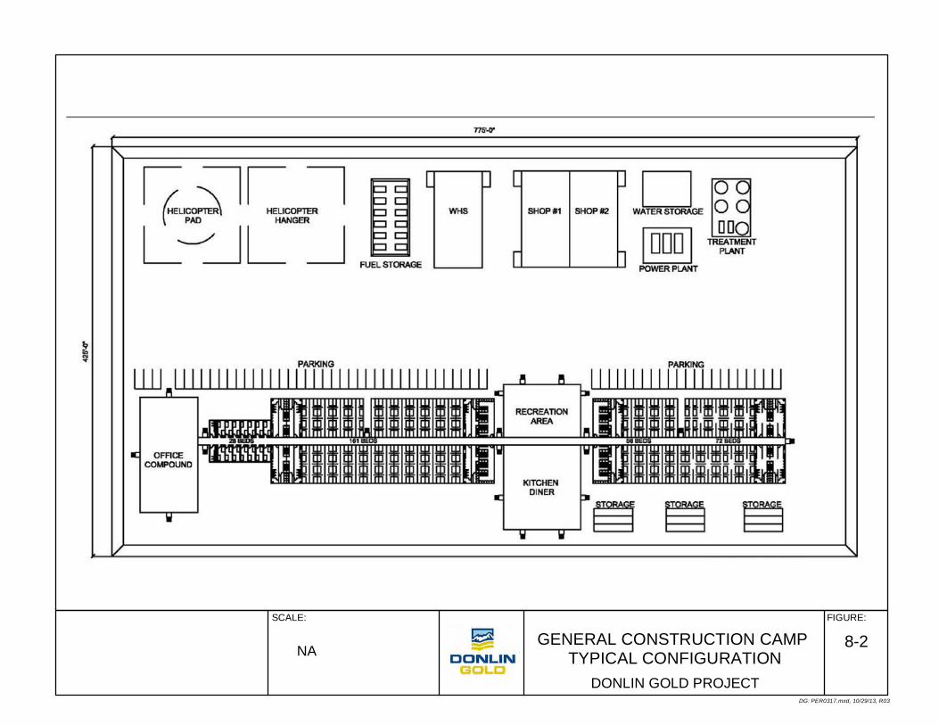
GENERAL CONSTRUCTION CAMP TYPICAL CONFIGURATION
FIGURE:SCALE:
DG: PER0317.mxd, 10/29/13, R03
DONLIN GOLD PROJECT
8-2NA
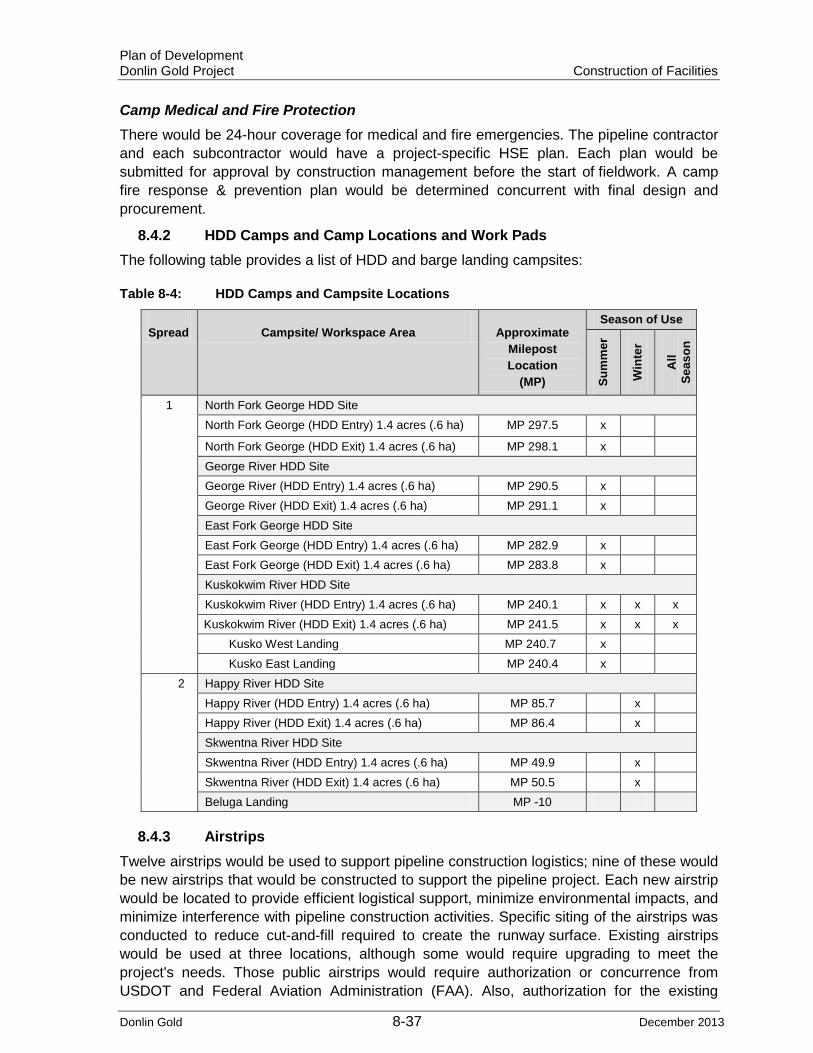
Plan of Development Donlin Gold Project Construction of Facilities
Donlin Gold 8-37 December 2013
Camp Medical and Fire Protection There would be 24-hour coverage for medical and fire emergencies. The pipeline contractor and each subcontractor would have a project-specific HSE plan. Each plan would be submitted for approval by construction management before the start of fieldwork. A camp fire response & prevention plan would be determined concurrent with final design and procurement.
8.4.2 HDD Camps and Camp Locations and Work Pads The following table provides a list of HDD and barge landing campsites:
Table 8-4: HDD Camps and Campsite Locations
Spread Campsite/ Workspace Area Approximate Milepost Location
(MP)
Season of Use
Sum
mer
Win
ter
All
Seas
on
1 North Fork George HDD Site North Fork George (HDD Entry) 1.4 acres (.6 ha) MP 297.5 x
North Fork George (HDD Exit) 1.4 acres (.6 ha) MP 298.1 x George River HDD Site George River (HDD Entry) 1.4 acres (.6 ha) MP 290.5 x George River (HDD Exit) 1.4 acres (.6 ha) MP 291.1 x East Fork George HDD Site East Fork George (HDD Entry) 1.4 acres (.6 ha) MP 282.9 x East Fork George (HDD Exit) 1.4 acres (.6 ha) MP 283.8 x Kuskokwim River HDD Site Kuskokwim River (HDD Entry) 1.4 acres (.6 ha) MP 240.1 x x x Kuskokwim River (HDD Exit) 1.4 acres (.6 ha) MP 241.5 x x x
Kusko West Landing MP 240.7 x Kusko East Landing MP 240.4 x
2 Happy River HDD Site Happy River (HDD Entry) 1.4 acres (.6 ha) MP 85.7 x Happy River (HDD Exit) 1.4 acres (.6 ha) MP 86.4 x Skwentna River HDD Site Skwentna River (HDD Entry) 1.4 acres (.6 ha) MP 49.9 x Skwentna River (HDD Exit) 1.4 acres (.6 ha) MP 50.5 x Beluga Landing MP -10
8.4.3 Airstrips Twelve airstrips would be used to support pipeline construction logistics; nine of these would be new airstrips that would be constructed to support the pipeline project. Each new airstrip would be located to provide efficient logistical support, minimize environmental impacts, and minimize interference with pipeline construction activities. Specific siting of the airstrips was conducted to reduce cut-and-fill required to create the runway surface. Existing airstrips would be used at three locations, although some would require upgrading to meet the project's needs. Those public airstrips would require authorization or concurrence from USDOT and Federal Aviation Administration (FAA). Also, authorization for the existing

Plan of Development Donlin Gold Project Construction of Facilities
Donlin Gold 8-38 December 2013
airstrips from the land owner would need to be verified. The twelve airstrips to be used would be instrumental in supporting mobilization of equipment and materials for project construction and to support camp operations during construction periods. Each location would require storage for air operations and staging for pipeline construction. Actual facilities, access control, security requirements, aircraft needs and freight requirements would be determined during final design. Appendix A shows location and land status for airstrips.

Plan of Development Donlin Gold Project Construction of Facilities
Donlin Gold 8-39 December 2013
Table 8-5: Airstrip Locations and Construction
Spread Name Approximate Milepost Location
(MP)
Length (ft/m)
Construction/Area Season of Use
Sum
mer
Win
ter
All
Seas
on
2 Beluga Airstrip Beluga 5,000 ft (1,524 m)
Existing-No work x x x
Deep Creek Airstrip MP 42.1 3,500 ft (1,067 m)
New- Grade, cut and fill 19.4 acres (7.9 ha)
x
Shell Airstrip* MP 54 5,000 ft (1,524 m)
New- Grade, cut and fill 103.7 acres (42 ha)
x
Happy River Airstrip MP 85.1 5,000 ft (1,524 m)
New- Grade, cut and fill 86.7 acres (35.1 ha)
x
Threemile Airstrip MP 111.8 3,500 ft (1,067)
New- Grade, cut and fill 27.9 acres (11.3 ha)
x x x
1 Bear Paw Airstrip MP133.8 4,000 ft (1,219 m)
New- Grade, cut and fill 26.8 acres (10.8 ha)
x
Jones Airstrip MP 144.9 5,000 ft (1,524 m)
New- Grade only, flood plain 84.3 acres (34.1 ha)
x x x
Farewell Airstrip MP 158.2 5,000 ft (1,524 m)
Existing- Grade only, surface course 139.9 acres (56.6 ha)
x x x
Big River Airstrip MP 191.6 5,000 ft (1,524 m)
New- Grade, cut and fill 62.3 acres (25.2 ha)
x
Kuskokwim East Airstrip
MP 235.7 5,000 ft (1,524 m)
New- Grade only 59.3 acres (24 ha) x x x
Kuskokwim West Airstrip
MP 246.2 5,000 ft (1,524 m)
New- Grade only 63 acres (25.5 ha) x x x
Donlin Gold Airstrip Donlin Gold Camp
5,000 ft (1,524 m)
Existing- No work x x x
*Use of the existing airstrip in Skwentna was evaluated and determined to not meet Donlin Gold’s needs.
8.4.4 Roads Graded or gravel fill access roads would be needed for all-season use; ice access roads would be for winter use only. Ice access roads would be used primarily to reach water sources that cannot be reached from the ROW and for access to the ROW for ice or snow workpad construction.
Donlin Gold proposes to develop an approximately 46 to 50 mile (74 to 81 km), 30 ft (9 m) wide winter access corridor (see Table 8-8 and accompanying map) to transport equipment and supplies for a period of approximately 3 years from the Parks Highway via Petersville Road or at Willow via the Willow Creek Parkway as described below. See also Appendix E for winter road typical construction and stream crossing plans.
Each of the two route options has been determined to be viable and the majority of each route has previously been utilized as commercial/industrial winter trails to support oil and gas exploration, mineral exploration and development, as well as materials and fuel transport for the numerous lodges and commercial activities in the Yentna and Skwentna River drainages. Since each route has distinct advantages depending on specific winter season conditions, and likely, but undetermined future use by other parties, it is appropriate to carry forward two primary route options. The 46 mile (74 m) long northern route alternative is identified as the “Oilwell Road Route” (OWRR). The 50 mile (81 km) long

Plan of Development Donlin Gold Project Construction of Facilities
Donlin Gold 8-40 December 2013
southern route is identified as the “Willow Landing Route” (WLR). Each primary route includes several spur options (secondary routes) which provide for access to the pipeline corridor at several different locations. In addition each of the primary routes share the same corridor for the final approximately 12 miles (19 km) approaching the pipeline corridor at its crossing of the Skwentna River (approximately pipeline MP 50). Ultimately the project would utilize one of the primary routes and each of the spur routes that access pipeline MP 32 and MP 43. A map of proposed winter construction access route options is included with Table 8-8.
Oilwell Road Route
Access to the start point of this route would be via the Parks Highway to Petersville Road then to Oilwell Road and south on Oilwell Road to the Amber Lake Area. From near Amber Lake the winter road would begin and follow the existing Oilwell Road ROW generally south and west across Kroto Creek to the currently utilized winter road crossing of the Kahiltna River. From the Kahiltna, the route would follow existing trials and old seismic lines to the Yentna River crossing in the vicinity of the area commonly known as “McDougal” and about 1 mile (1.6 km) downriver of the mouth of Lake Creek. From the crossing of the Yentna River the route would continue southwesterly for several miles, mostly following existing winter trail routes, before turning more westerly and crossing Eightmile Creek approximately 2 miles (3.2 km) north of Eightmile Lake. From this point the route would primarily traverse open marshy areas and bogs until it arrives at the Skwentna River approximately 2.5 miles (4 km) downriver of the mouth of Shell Creek.
Willow Landing Route This route would be accessed from the Parks Highway at Willow via Willow Creek Parkway. The recently reestablished winter trail route begins at the west end of Willow Creek Parkway on the east bank of the Susitna River, just downriver of Willow Creek. For the first approximately 4.5 miles (7.2 km) the route crosses numerous channels and islands that make up the Susitna River floodplain. Once on the elevated outwash terrace above the river floodplain, the trail crosses mostly open marsh areas before dropping down to cross the Deshka River at a point roughly 10 miles (16 km) upriver of its confluence with the Susitna River. From the Deshka River the route would continue westward for approximately 14 miles (22.5 km) crossing open marshy areas and low ridges as it approaches the Yentna River where it would cross just below the mouth of Moose Creek. After crossing the Yentna River the route trends west to a crossing of Kutna Creek, then northwesterly over open marsh lands to the Skwentna River Crossing. This route would be a few miles longer than the Oilwell Road Route but would eliminate many miles of highway and secondary road travel. It also would provide a more direct access via a spur route to approximately MP 32 of the pipeline corridor.
Three spur routes have been defined which allow access to the pipeline corridor from the primary routes. The Deep Creek Spur Route is roughly eight miles in length and traverses open marsh land and woodlands following an existing seismic line trail. This spur provides access to a favorable temporary camp and staging area location near pipeline MP 43. From the Deep Creek Spur Route, another 13 mile (21 km) long spur road (Bear Creek Spur Route) would provide access to the pipeline corridor at approximately MP 32. If the Willow Landing Route is developed as the primary access, a spur road (Alexander Spur Route) from near the crossing of Kutna Creek would be developed over mostly open marshland to access the pipeline corridor at approximately MP 32.

Plan of Development Donlin Gold Project Construction of Facilities
Donlin Gold 8-41 December 2013
Land that would be traversed by each route is State owned and managed. The extreme north end of the OWRR would utilize a public ROW through Matanuska-Susitna Borough land. No private parcels would be crossed by the proposed trails.
Winter road routes have been planned to avoid steep topographic relief, maximize use of existing winter roads or trails and maximize the use of open and marshy areas that freeze sufficiently and require minimal clearing. In addition, undesirable cross slopes have been avoided to the extent possible. Very limited sections along the existing Oilwell Road Route would require limited cut and fill to repair the road where sloughing has occurred and grades are excessively steep. Stream and river crossings have been selected which have been historically utilized and/or require minimal disturbance to develop adequate crossings for heavy equipment and loads. Water for winter road surface hardening and building ice at stream crossings would be requested from nearly all significant flowing waters that are crossed by the various routes as identified in Table 8-12a.
Initial route verification and reconnaissance was completed during the winters of 2010 through 2013. On the ground traverse of each route was completed by RECON, LLC engineering staff utilizing snowmachines. Aerial reconnaissance was completed using helicopters during both summer and winter seasons.
Mobilization of road pioneering and clearing/mulching equipment would begin in the winter before pipeline construction and as soon as frozen ground conditions would support the weight of equipment. This equipment would be used to clear trees and brush without damaging ground that would result in erosion or long term vegetation loss. Overland mobilization of all construction support equipment would occur during the winter on frozen trails or roads with either tracked or rubber-tire vehicles. Substantial portions of access routes would occur in previously disturbed areas. Maintenance of the ROW would only occur during the winter months by packing, watering, and grading the snow and ice surface.
The purpose of the winter access would be to:
• Provide access to the pipeline corridor directly from the road system so that equipment, materials, camps and fuel could be staged and supplied along the pipeline corridor for and during construction.
• Provide access so that all materials, fuel and equipment needed for the approximately 130 miles (209 km) of pipeline south of the Tatina River do not have to be transported from the proposed barge landing on Cook Inlet at Beluga then over the road to Theodore River, and over a supply road along the pipeline corridor and through the Susitna Game Refuge.
• Facilitate multiple construction headings along the pipeline corridor thereby reducing the number of field seasons that would be needed to complete construction.
• Eliminate the need to access and maintain a road along the pipeline corridor from Beluga and over the pass to the Susitna Drainage for more than one winter season.
The Tatlawiksuk Route, also identified in Table 8-8 as a winter access route, bypasses the hilly terrain between approximately MP 224 and MP 231 to provide faster and safer access for construction vehicles transiting the area. This route is also shown in Appendix A.

Plan of Development Donlin Gold Project Construction of Facilities
Donlin Gold 8-42 December 2013
Table 8-6: Temporary Site Access Roads
Name Milepost (MP)
Length (m)
Length (km) Type Description
Season of Use
Sum
mer
Win
ter
All
Seas
on
Public Road Easement
Existing access from Beluga airstrip to MP 0 x x x
Public Road Easement Existing Pretty Creek Road x x x
AWES-0030 MP 10 0.43 0.69 Water Extraction Site Access
x
AWES-0031 MP 10 0.23 0.37 Water Extraction Site Access x
AWES-0080 MP 21 0.82 1.32 Water Extraction Site Access x
AWES-0085 MP 22 0.46 0.74 Water Extraction Site Access x
AWES-0115 MP 35 1.52 2.45 Water Extraction Site Access x
AWES-0140 MP 39 0.85 1.37 Water Extraction Site Access x
AWES-0165 MP 47 0.1 0.16 Water Extraction Site Access x
AWES-0170 MP 48 0.33 0.53 Water Extraction Site Access
x
AWES-0190 MP 53 0.11 0.18 Water Extraction Site Access
x
AWES-0210 MP 56 0.05 0.08 Water Extraction Site Access
x
AWES-0220 MP 56 0.32 0.51 Water Extraction Site Access
x
AMS-11 MP 56 0.87 1.40 Material Site Access x
AWES-0245 MP 64 0.08 0.13 Water Extraction Site Access
x
AWES-270 MP 73 0.16 0.26 Water Extraction Site Access
x
AWES-0300 MP 84 0.12 0.19 Water Extraction Site Access
x
AWES-0310 MP 86 0.09 0.14 Water Extraction Site Access
x
AWES-0320 MP 88 0.1 0.16 Water Extraction Site Access x
AWES-0330 MP 90 0.13 0.21 Water Extraction Site Access x
AWES-0350 MP 99 0.06 0.10 Water Extraction Site Access x
AWES-0380 MP 106 0.26 0.42 Water Extraction Site Access x
AWES-0418 MP 112 0.06 0.10 Water Extraction Site Access x x x
AMS-17C MP 114 0.25 0.40 Material Site Access x
AWES-0460 MP 130 0.05 0.08 Water Extraction Site Access x
AWES-0462 MP 131 0.05 0.08 Water Extraction Site Access x
AWES-0490 MP 145 0.34 0.55 Water Extraction Site Access x x x
AWES-0520 MP 156 0.6 0.10 Water Extraction Site Access x
AAS-Farewell MP 156 2.98 4.80 Airstrip Access x x x
AWES-0545 MP 167 0.07 0.11 Water Extraction Site Access x
AWES-0615 MP 186 0.19 0.31 Water Extraction Site Access x
AWES-0620 MP 188 0.14 0.23 Water Extraction Site Access x
AWES-0625 MP 189 0.1 0.16 Water Extraction Site Access x
AWES-0640 MP 193 0.4 0.64 Water Extraction Site Access x
AWES-0650 MP 197 0.06 0.10 Water Extraction Site Access x
AWES-0660 MP 198 0.42 0.68 Water Extraction Site Access x

Plan of Development Donlin Gold Project Construction of Facilities
Donlin Gold 8-43 December 2013
Name Milepost (MP)
Length (m)
Length (km) Type Description Season of Use
AMS-42 MP 213 0.24 0.39 Material Site Access x
AMS-44 MP 223 0.47 0.76 Material Site Access x
AWES-0730 MP 224 0.45 0.72 Water Extraction Site Access x
AWES-0750 MP 227 1.17 1.88 Water Extraction Site Access x
AWES-0770 MP 239 0.1 0.16 Water Extraction Site Access x x x
AMS-50 MP 239 0.08 0.13 Material Site Access x x x
AWP-Kusko NE MP 240 0.7 0.11 Work Pad x x x
AWES-0790 MP 241 0.14 0.23 Water Extraction Site Access x x x
AWES-0810 MP 245 0.1 0.16 Water Extraction Site Access x x x

Plan of Development Donlin Gold Project Construction of Facilities
Donlin Gold 8-44 December 2013
Table 8-7: Shoofly Access Routes
Name Approximate Milepost
(MP) Length (m) Length (km)
Season of Use
Sum
mer
Win
ter
All
Seas
on
SHOO-0005 P 4.7 0.71 1.14 x x x
SHOO-0010 MP 11.4 0.84 1.35 x
SHOO-0020 MP 14.3 0.48 0.77 x
SHOO-0030 MP 16.8 0.26 0.42 x
SHOO-0040 MP 19.8 1.06 1.71 x
SHOO-0050 MP 45 0.31 0.50 x
SHOO-0060 MP 49.5 0.63 1.01 x
SHOO-0070 MP 50.6 0.24 0.39 x
SHOO-0080 MP 51 0.85 1.37 x
SHOO-0090 MP 59.3 0.15 0.24 x
SHOO-0100 MP 68 0.11 0.18 x
SHOO-0110 MP 70.5 0.09 0.14 x
SHOO-0120 MP 75.2 0.3 0.48 x
SHOO-0130 MP 85.8 1.64 2.64 x
SHOO-0140 MP 87 1.19 1.92 x
SHOO-0150 MP 88.1 0.33 0.53 x
SHOO-0160 MP 98.2 0.2 0.32 x
SHOO-0170 MP 102.6 0.63 1.01 x
SHOO-0180 MP 108.3 0.64 1.03 x
SHOO-0190 MP 108.7 0.37 0.60 x
SHOO-0200 MP 115.9 0.68 1.09 x
SHOO-0210 MP 116.6 0.78 1.26 x
SHOO-0220 MP 119.7 0.30 0.48 x
SHOO-0230 MP 120.1 0.36 0.58 x
SHOO-0240 MP 124.9 0.39 0.63 x
SHOO-0250 MP 126.3 0.21 0.34 x
SHOO-0260 MP 126.7 0.86 1.38 x
SHOO-0270 MP 127.5 1.22 1.96 x
SHOO-0280 MP 128.5 0.64 1.03 x
SHOO-0290 MP 137.1 0.14 0.23 x
SHOO-0300 MP 137.7 0.74 1.19 x
SHOO-0310 MP 139.8 0.59 0.95 x
SHOO-0320 MP 141 0.17 0.27 x
SHOO-0330 MP 142 0.13 0.21 x
SHOO-0340 MP 142.9 1.6 2.57 x
SHOO-0350 MP 149 0.49 0.79 x
SHOO-0360 MP 149.6 1.27 2.04 x

Plan of Development Donlin Gold Project Construction of Facilities
Donlin Gold 8-45 December 2013
Name Approximate Milepost (MP) Length (m) Length (km)
Season of Use
Sum
mer
Win
ter
All
Seas
on
SHOO-0370 MP 167.8 0.17 0.27 x
SHOO-0380 MP 168.2 1.03 1.66 x
SHOO-0390 MP 182.4 0.19 0.31 x
SHOO-0400 MP 182.9 0.67 1.08 x
SHOO-0410 MP 186 0.24 0.39 x
SHOO-0420 MP 191.9 0.63 1.01 x
SHOO-0430 MP 197.1 1.06 1.71 x
SHOO-0440 MP 234.9 3.12 5.02 x x x
SHOO-0450 MP 236 4.8 7.72 x x x
SHOO-0460 MP 240.9 6.91 11.12 x x x
SHOO-0470 MP 246.9 0.36 0.58 x x x
SHOO-0480 MP 248.5. 1.92 3.09 x
SHOO-0490 MP 255.9 1.14 1.83 x
SHOO-0500 MP 258.8 2.99 4.81 x
SHOO-0510 MP 262.9 2.13 3.43 x
SHOO-0520 MP 268.8 1.68 2.70 x
SHOO-0530 MP 270.2 1.46 2.35 x
SHOO-0540 MP 272.9 0.72 1.16 x
SHOO-0550 MP 274.3 0.47 0.76 x
SHOO-0560 MP 275.9 0.38 0.61 x
SHOO-0570 MP 276.9 0.46 0.74 x
SHOO-0580 MP 277.6 0.35 0.56 x
SHOO-0590 MP 278.6 0.59 0.95 x
SHOO-0600 MP 279.4 0.41 0.66 x
SHOO-0610 MP 280.8 0.73 1.17 x
SHOO-0620 MP 281.6 0.85 1.37 x
SHOO-0630 MP 282.9 1 1.6 x
SHOO-0640 MP 283.9 1.95 3.14 x
SHOO-0650 MP 285.9 2.71 4.36 x
SHOO-0660 MP 288 0.88 1.42 x
SHOO-0670 MP 288.9 0.66 1.06 x
SHOO-0680 MP 290 1.18 1.90 x
SHOO-0690 MP 291.4 0.37 0.60 x
SHOO-0700 MP 295.9 2.32 3.73 x
SHOO-0710 MP 298.1 1.47 2.37 x
SHOO-0720 MP 299.3 0.59 0.95 x
SHOO-0730 MP 307.7 0.65 1.05 x
SHOO-0740 MP 312.8 6.37 10.25 x

Plan of Development Donlin Gold Project Construction of Facilities
Donlin Gold 8-46 December 2013
Table 8-8: Winter Access Routes with Susitna Valley Winter Map
Name Nearest Milepost
(MP) Length (m/km) Class
Season of Use
Sum
mer
Win
ter
All
Seas
on
Tatlawiksuk Route MP 231 7.54 miles (12.13 km) Construction Access x
Big Bend Trail MP 32 26.54 miles (42.71 km) Construction Access x
Bear Creek Route MP 32 13.13 miles (21.13 km) Construction Access x
Deep Creek Route MP 43 7.81 miles (12.55 km) Construction Access x
Oil Well Road Route MP 50 45.61 miles (73.40 km) Construction Access x
Kutna Route MP 38 12.23 miles (19.68 km) Construction Access x
Alexander Route MP 36 8.68 miles (13.97 km) Construction Access x

Plan of Development Donlin Gold Project Construction of Facilities
Donlin Gold 8-47 December 2013
8.4.5 Material Sites Material sites would be needed to provide granular fill material for access and shoofly roads, airfields, camp pads, PSYs, the compressor station and meter pads, and granular workpads (if they are used). Material sites would also be the source and location for processing plants for crushed and/or screened material for select backfill, bedding, padding, surface courses, cobbles, rock riprap, and other types of granular material. All material used would be analyzed to be sure that it was appropriate to be used in contact with the pipe.
Approximately 70 potential material sites (Table 8-9) to supply granular materials have been identified along the proposed ROW, based on terrain type and geology. These sites would be developed as required to supply the needed granular materials for this project. Table 8-6 and Table 8-7 show temporary site access roads and pipeline shoofly access roads. The location and number of material sites that also may require a processing plant/crusher would be determined during final design. Material sites are located to accommodate construction material needs, where appropriate materials can be found, and to minimize haul distances. Material would be transported by haul equipment along access roads and the pipeline travel way. Specific haul equipment would be determined during final design.
The frequency and size of material sites would be determined by the need for particular amounts of material along the pipeline route. Variables that would determine the need for a material site include ROW mode, construction season, distance to water for ice pad in winter, location of camps, PSYs, haul distances, suitability of mined material, environmental issues, and availability of candidate sites. Material sites would be located and sized to avoid sensitive areas such as wetlands, cultural sites, sensitive species habitat, or other environmentally sensitive areas. All activities at material sites would be conducted in accordance with required permits and authorizations and associated stipulations for protection of resources such as air and water quality.
Current estimates call for more than 55,000 cubic yards (42,050 m3) of select backfill (bedding and padding) to be produced, hauled from material sites to the ROW, and placed under (bedding) and around (padding) the pipeline in the trench in ice-rich soils. The trench spoil would be mounded over the select backfill to provide for settlement after thawing. A total of 300 miles (483 km) of pipe would be padded with material screened from the trench spoil, with trencher cuttings where appropriate or with native trench spoil, i.e., no imported gravel would be needed.
The civil work would include an estimated 800,000 to 1,000,000 yd3 (611,644 to 764,555 m3) of gravel that would be mined, hauled, and placed as site pads for the compressor station, PSYs, MLVs, construction campsites, and airstrips. In addition, an estimated 700,000 to 1,000,000 yd3 (535,188 to 764,555 m3) of gravel would be placed for access roads. These values are estimates that would be reevaluated and refined to determine more accurately the material quantities required as the project progresses.

Plan of Development Donlin Gold Project Construction of Facilities
Donlin Gold 8-48 December 2013
Table 8-9: Potential Material Sites
Material Site
Name
Nearest Milepost
(MP)
Area in Acres (ha)
Material Type
Estimated Available Volume
(yd3)
Estimated Expected
Usage (yd3)
Season of Use
Sum
mer
Win
ter
All
Seas
on
MS-00 MP 0.5 13.3 acres (5.4 ha)
Gravel 50,000 30,000 x
MS-01 MP 5.1 14.7 acres (5.9 ha)
Gravel 75,000 75,000 x
MS-02 MP 10.2 6.2 acres (2.5 ha)
Bedrock 20,000 20,000 x
MS-03 MP 16.6 5.6 acres (2.3 ha)
Bedrock 20,000 20,000 x
MS-04 MP 20.1 4.7 acres (1.9 ha)
Bedrock 20,000 20,000 x
MS-05 MP 26.1 16.5 acres (6.7 ha)
Gravel 50,000 20,000 x
MS-06 MP 32.5 4.7 acres (1.9 ha)
Gravel 20,000 20,000 x
MS-07 MP 36.2 3.7 acres (1.5 ha)
Gravel 20,000 20,000 x
MS-08 MP 42.3 7 acres (2.8 ha)
Gravel 150,000 150,000 x
MS-09 MP 45 16.1 acres (6.5 ha)
Gravel 100,000 50,000 x
MS-10 MP 50.5 17.1 acres (6.9 ha)
Gravel 20,000 20,000 x
MS-11 MP 55.8 36.3 acres (14.7 ha)
Alluvial Gravel 250,000 250,000 x
MS-12 MP 68.3 3.6 acres (1.4 ha)
Gravel 20,000 20,000 x
MS-13 MP 85.3 15.9 acres (6.4 ha)
Alluvial Gravel 100,000 100,000 x
MS-14 MP 88 5.2 acres (2.1 ha)
Alluvial Gravel 20,000 20,000 x
MS-16 MP 102.9 9.1 acres (3.7 ha)
Alluvial Gravel 20,000 20,000 x
MS-17A MP 108.4 31.6 acres (12.8 ha)
Alluvial Gravel 250,000 20,000 x
MS-17B J 112 29.8 acres (12.1 ha)
Alluvial Gravel 150,000 150,000 x x x
MS-17C MP 114.4 19.7 acres (8 ha)
Alluvial Gravel 20,000 20,000 x
MS-18A MP 119.9 5.3 acres (2.1 ha)
Course Colluvial 15,000 10,000 x
MS-18B MP 120.3 3.6 acres (1.4 ha)
Alluvial Gravel 15,000 10,000 x
MS-18C MP 121.3 4.6 acres (1.9 ha)
Alluvial Gravel 15,000 10,000 x
MS-19A MP 123.3 1.8 acres (0.7 ha)
Alluvial Gravel 15,000 10,000 x
MS-19B MP 124.8 13.4 acres (5.4 ha)
Coarse Colluvial 25,000 25,000 x

Plan of Development Donlin Gold Project Construction of Facilities
Donlin Gold 8-49 December 2013
Material Site
Name
Nearest Milepost
(MP)
Area in Acres (ha)
Material Type Estimated Available Volume
(yd3)
Estimated Expected
Usage (yd3)
Season of Use
Sum
mer
Win
ter
All
Seas
on
MS-20 MP 127 18.5 acres (7.5 ha)
Alluvial Outwash Gravel 100,000 50,000 x
MS-21 MP 130.3 26.5 acres (10.7 ha)
Bedrock & Alluvial Gravel 100,000 50,000 x
MS-22 MP 133.7 21.5 acres (8.7 ha)
Alluvial Gravel 100,000 100,000 x
MS-23 MP 138.5 14.6 acres (5.9 ha)
Glacial/ Alluvial Gravel 50,000 20,000 x
MS-24 MP 144.9 20.6 acres (8.3 ha)
Alluvial Gravel 250,000 150,000 x x x
MS-25 MP 147.5 42.9 acres (17.4 ha)
Alluvial Gravel 1,000,000 15,000 x
MS-26 MP 152 44.1 acres (17.8 ha)
Alluvial Gravel 1,000,000 150,000 x
MS-27 MP 156.5 11 acres (4.4 ha)
Gravel 250,000 200,000 x
MS-27A MP 159.6 3.3 acres (1.3 ha)
Alluvial Gravel 100,000 100,000 x
MS-28 MP 160.6 7.4 acres (3 ha)
Gravel 200,000 30,000 x
MS-28A MP 162.7 8.9 acres (3.6 ha)
Alluvial Gravel 200,000 75,000 x
MS-29 MP 164.2 7.4 acres (3 ha)
Gravel 200,000 45,000 x
MS-30 MP 168.2 14 acres (5.7 ha)
Gravel 250,000 125,000 x
MS-31 MP 170.8 7.5 acres (3 ha)
Gravel 200,000 80,000 x
MS-32 MP 174.2 11.1 acres (4.5 ha)
Gravel 250,000 100,000 x
MS-33 MP 176.7 6 acres (2.4 ha)
Gravel 100,000 60,000 x
MS-34 MP 178.9 5 acres (2 ha)
Gravel 75,000 50,000 x
MS-35 MP 182.9 13.5 acres (5.4 ha)
Gravel 300,000 110,000 x
MS-36 MP 184.9 6.9 acres (2.8 ha)
Gravel 100,000 100,000 x
MS-38 MP 190.9 5.2 acres (2.1 ha)
Gravel 150,000 150,000 x
MS-39 MP 191.8 7.4 acres (3 ha)
Gravel 150,000 150,000 x
MS-40 MP 198 18.7 acres (7.6 ha)
Gravel 150,000 135,000 x
MS-41 MP 204.8 11.6 acres (4.7 ha)
Gravel 100,000 90,000 x
MS-42 MP 213.2 39.5 acres (16 ha)
Bedrock 1,000,000 350,000 x
MS-43 MP 216.8 7.8 acres (3.2 ha)
Bedrock 75,000 75,000 x

Plan of Development Donlin Gold Project Construction of Facilities
Donlin Gold 8-50 December 2013
Material Site
Name
Nearest Milepost (MP)
Area in Acres (ha)
Material Type Estimated Available Volume (yd3)
Estimated Expected Usage (yd3)
Season of Use
Sum
mer
Win
ter
All
Seas
on
MS-44 MP 222.4 43.5 acres (17.6 ha)
Bedrock 1,000,000 150,000 x
MS-45 MP 225.9 24 acres (9.7 ha)
Bedrock 500,000 240,000 x
MS-46 MP 229.9 19.6 acres (7.9 ha)
Bedrock 250,000 120,000 x
MS-47 MP 231.9 18.5 acres (7.5 ha)
Bedrock 150,000 60,000 x
MS-48 MP 234.9 61.8 acres (25 ha)
Bedrock 250,000 100,000 x x x
MS-49 MP 235.6 15.5 acres (6.3 ha)
Bedrock 150,000 150,000 x x x
MS-50 MP 239.4 25.6 acres (10.3 ha)
Bedrock 200,000 200,000 x x x
MS-52 MP 241 48.6 acres (19.7 ha)
Bedrock & Gravel 1,000,000 250,000 x x x
MS-53 MP 243.4 23.5 acres (9.5 ha)
Bedrock 150,000 120,000 x x x
MS-54 MP 247 32.9 acres (13.3 ha)
Bedrock 500,000 300,000 x x x
MS-55 MP 254.7 3.7 acres (1.5 ha)
Bedrock 50,000 25,000 x
MS-56 MP 256.8 3.3 acres (1.3 ha)
Bedrock 50,000 25,000 x
MS-57 MP 264.2 3.7 acres (1.5 ha)
Bedrock 50,000 25,000 x
MS-58 MP 269.2 3.7 acres (1.5 ha)
Bedrock 50,000 25,000 x
MS-59 MP 281.5 13 acres (5.3 ha)
Bedrock 200,000 50,000 x
MS-60 MP 284.7 15 acres (6.1 ha)
Bedrock 200,000 50,000 x
MS-60A MP 284 9.9 acres (4 ha)
Bedrock 200,000 50,000 x
MS-61 MP 290.4 11.6 acres (4.7 ha)
Bedrock 200,000 50,000 x
MS-61A MP 2914 4.7 acres (1.9 ha)
Bedrock 50,000 50,000 x
MS-62 MP 293.9 21.3 acres (8.6 ha)
Bedrock 300,000 100,000 x
MS-63 MP 298.8 10 acres (4 ha)
Bedrock 200,000 100,000 x
Table 8-10: Pipeline Shoofly and Access Roads Material Needs
Table 8-10 would be prepared during final design.
Material site boundaries would be shaped in a manner as to blend with surrounding natural land patterns. Regardless of the layout of material sites, primary emphasis would be placed
Plan of Development Donlin Gold Project Construction of Facilities
Donlin Gold 8-51 December 2013
on prevention of soil erosion and damage to vegetation. All material sites would be reclaimed consistent with approved reclamation plans for each site. Final volumes of these granular materials and specific location of material sites and development plans for these sites would be part of the final pipeline design. Material sale applications would be separate from the ROW applications.
8.4.6 Pipe Storage Yards
Pipe storage yards/material stockpiling sites Main pipe storage/equipment staging yards are planned for Bethel, Beluga, the Donlin Gold mine site, Oil Well Road area and near the barge landing sites on the Kuskokwim River. These yards would serve as the primary staging points for pipe materials for sorting and delivery to the 57 PSYs spaced at intervals of approximately 5 miles (8 km) along the ROW. Hauling and staging at the PSYs along the ROW would occur during the civil clearing and access season, which generally would be 1 year before the pipe laying season.
The majority of the heavy equipment required for project construction would also be staged from these locations. Most of the pipeline material and equipment would come through the staging yards at Beluga and Bethel. There would be 31 PSYs located in Spread 1 (not including the Donlin Gold Mine Site) and 26 (not including Beluga) located in Spread 2. A complete list of proposed PSYs and their approximate locations is provided in Table 8-11. Each PSY location would also be shown on the project alignment sheets. In addition to pipe, PSYs would store mainline valves, induction bends, fiber optic cable, and other materials. The sequencing and installation of the pipeline and fiber optic cable must be coordinated to minimize ROW disturbance and to utilize existing pipeline storage sites and the pipeline ROW before they are reclaimed. Equipment staging sites would be located close to the kickoff point for each section. These sites would be used to receive and store equipment during periods of no construction between seasons.
Staging areas would be cleared and graded before use. Any overburden would be salvaged and stockpiled for reclamation. When no longer needed for construction purposes, the sites would be reclaimed. Stockpiled overburden would be spread on the reclaimed areas to improve soil and facilitate natural revegetation. The staging area may be a gravel pad or non-permanent porous pavement panels if the natural soil is not suitable. If gravel is used, the gravel would be left in place when the sites are reclaimed when no longer needed for construction.

Plan of Development Donlin Gold Project Construction of Facilities
Donlin Gold 8-52 December 2013
Table 8-11: Pipe Storage Yards
Name Approximate
Milepost (MP)
Area (acres/
hectares)
Season of Use
Planned Pipe Source Sum
mer
Win
ter
All
Seas
on
Beluga Yard*
Beluga
PSY-01 MP 6.8 1.5 acres (0.6 ha) x Beluga
PSY-02 MP 12.8 1.5 acres (0.6 ha) x Beluga
PSY-03 MP 15.4 1.5 acres (0.6 ha) x Beluga
PSY-04 MP 21.8 1.5 acres (0.6 ha) x Beluga
PSY-05 MP 28.2 1.5 acres (0.6 ha) x Beluga
PSY-06 MP 32.5 1.5 acres (0.6 ha) x Beluga
PSY-07 MP 37.5 1.5 acres (0.6 ha) x Beluga
PSY-08 MP 42.3 1.5 acres (0.6 ha) x Road system than via ice road **
PSY-09 MP 46.7 1.5 acres (0.6 ha) x Road system than via ice road **
PSY-10 MP 50.8 1.5 acres (0.6 ha) x Road system than via ice road **
PSY-11 MP 54.2 1.5 acres (0.6 ha) x Road system than via ice road **
PSY-12 MP 69.8 1.5 acres (0.6 ha) x Road system than via ice road **
PSY-13 MP 63.2 1.5 acres (0.6 ha) x Road system than via ice road **
PSY-14 MP 68.5 1.5 acres (0.6 ha) x Road system than via ice road **
PSY-15 MP 70.8 1.5 acres (0.6 ha) x Road system than via ice road **
PSY-16 MP 75.7 1.5 acres (0.6 ha) x Road system than via ice road **
PSY-17 MP 79.1 1.5 acres (0.6 ha) x Road system than via ice road **
PSY-18 MP 87 1.5 acres (0.6 ha) x Road system than via ice road **
PSY-19 MP 90.7 1.5 acres (0.6 ha) x Road system than via ice road **
PSY-20 MP 96.8 1.5 acres (0.6 ha) x Road system than via ice road **
PSY-21 MP 101.9 1.5 acres (0.6 ha) x Road system than via ice road **
PSY-22 MP 106.4 1.5 acres (0.6 ha) x Road system than via ice road **
PSY-23 MP 112.2 1.5 acres (0.6 ha) x x x Road system than via ice road **
PSY-24 MP 114.4 1.5 acres (0.6 ha) x Road system than via ice road **
PSY-25 MP 120.6 1.5 acres (0.6 ha) x Road system than via ice road **
PSY-26 MP 125.2 1.5 acres (0.6 ha) x Road system than via ice road **
PSY-27 MP 132.3 1.5 acres (0.6 ha) x Kusko East
PSY-28 MP 138.4 1.5 acres (0.6 ha) x Kusko East
PSY-29 MP 142.7 1.5 acres (0.6 ha) x Kusko East
PSY-30 MP 148 1.5 acres (0.6 ha) x Kusko East
PSY-31 MP 154 1.5 acres (0.6 ha) x Kusko East
PSY-32 MP 159.6 1.5 acres (0.6 ha) x Kusko East
PSY-33 MP 162.7 1.5 acres (0.6 ha) x Kusko East
PSY-34 MP 167.8 1.5 acres (0.6 ha) x Kusko East
PSY-35 MP 174.3 1.5 acres (0.6 ha) x Kusko East
PSY-36 MP 178.5 1.5 acres (0.6 ha) x Kusko East
PSY-37 MP 184.9 1.5 acres (0.6 ha) x Kusko East

Plan of Development Donlin Gold Project Construction of Facilities
Donlin Gold 8-53 December 2013
Name Approximate Milepost (MP) Area (acres/hectares)
Season of Use
Planned Pipe Source Sum
mer
Win
ter
All
Seas
on
PSY-38 MP 191.9 1.5 acres (0.6 ha) x Kusko East
PSY-39 MP 197.7 1.5 acres (0.6 ha) x Kusko East
PSY-40 MP 204.3 1.5 acres (0.6 ha) x Kusko East
PSY-41 MP 210.4 1.5 acres (0.6 ha) x Kusko East
PSY-42 MP 215.9 1.5 acres (0.6 ha) x Kusko East
PSY-43 MP 220.9 1.5 acres (0.6 ha) x Kusko East
PSY-44 MP 226.8 1.5 acres (0.6 ha) x Kusko West
PSY-45 MP 231.9 1.5 acres (0.6 ha) x Kusko West
PSY-46 MP 250.4 1.5 acres (0.6 ha) x Kusko West
PSY-47 MP 254.3 1.5 acres (0.6 ha) x Kusko West
PSY-48 MP 261.3 1.5 acres (0.6 ha) x Donlin Mine
PSY-49 MP 267.9 1.5 acres (0.6 ha) x Donlin Mine
PSY-50 MP 271.8 1.5 acres (0.6 ha) x Donlin Mine
PSY-51 MP 276.7 1.5 acres (0.6 ha) x Donlin Mine
PSY-52 MP 281.6 1.5 acres (0.6 ha) x Donlin Mine
PSY-53 MP 284.9 1.5 acres (0.6 ha) x Donlin Mine
PSY-54 MP 289.4 1.5 acres (0.6 ha) x Donlin Mine
PSY-55 MP 295.4 1.5 acres (0.6 ha) x Donlin Mine
PSY-56 MP 302.9 1.5 acres (0.6 ha) x Donlin Mine
PSY-57 MP 308.5 1.5 acres (0.6 ha) x Donlin Mine
Notes: *This yard is not laid out; it is assumed there is adequate room at Beluga. Start pipe haul from Beluga. ** Actual winter access route options (Oilwell Road Route or Willow Landing Route) are still being evaluated and are discussed in Section 8.4.4.
8.4.7 Water Use and Potential Water Extraction Sites Estimated annual water use requirements from sources are shown in Table 8-12. Final estimated quantities for specific uses would be determined during final design. Water required for camp use during construction would be supplied from wells or clean water sources and would be piped or trucked to a water treatment facility. There would also be water storage at each camp for fire suppression. Water would also be needed for other uses including ice road construction, dust control, reclamation and hydrostatic testing and HDD operations. Water withdrawal from lakes and streams would be planned and executed in accordance with the requirements of the appropriate permits and authorizations. Temporary water use authorizations would be applied for by either the appropriate contractor or Donlin Gold.
BLM has started The Bering Sea Western Interior Resource Management Plan. This study will include waterways located on BLM lands near the proposed pipeline route. Any Outstandingly Remarkable Values (ORVs) identified from the study will have guidelines established for future management in order to protect river values. If a decision on the Donlin Gold pipeline occurs after the completion of the Bering Sea Western Interior Resource Management Plan Record of Decision, the proposed pipeline may be subject to these guidelines.

Plan of Development Donlin Gold Project Construction of Facilities
Donlin Gold 8-54 December 2013
Table 8-12: Potential Water Extraction Sites
Water Extraction Site
Name
Nearest Milepost
(MP)
Season of Use Waterbody Type
Years of Use
Extraction
Sum
mer
Win
ter
All
Seas
on Rate
(gpm) Annual Volume
(gal)
WES-0010 MP 0 x River 1 500 3,430,000
WES-0020 MP 5 x River 1 500 3,860,000
WES-0030 MP 10 x Pond 1 500 500,000
WES-0031 MP 9 x Pond 1 500 500,000
WES-0040 MP 12 x Tributary 1 100 50,000
WES-0050 MP 14 x Tributary 1 100 50,000
WES-0060 MP 17 x Creek 1 500 1,200,000
WES-0070 MP 19 x Tributary 1 500 1,200,000
WES-0080 MP 21 x Tributary 1 500 1,200,000
WES-0085 MP 23 x Creek 1 100 500,000
WES-0090 MP 26 x Creek 1 250 1,200,000
WES-0095 MP 27 x Creek 1 250 1,600,000
WES-0096 MP 29 x Creek 1 500 1,200,000
WES-0100 MP 30 x Tributary 1 100 1,200,000
WES-0110 MP 33 x Creek 1 500 1,800,000
WES-0115 MP 35 x Creek 1 500 1,200,000
WES-0120 MP 37
x
Creek 1 500 1,200,000
WES-0130 MP 39
x
Tributary 1 500 1,200,000
WES-0140 MP 39 x Creek 1 500 1,200,000
WES-0145 MP 41
x
Creek 1 500 1,200,000
WES-146 MP 42 x Creek 1 500 1,930,000
WES-0150 MP 43
x
Creek 1 500 1,200,000
WES-0160 MP 45
x
Creek 1 250 1,200,000
WES-165 MP 47 x Pond 1 500 600,000
WES-0170 MP 48
x
Pond 1 500 1,200,000
WES-0180 MP 50
x
River 2 600 5,265,000
WES-0190 MP 53
x
Creek 2 500 900,000
WES-0200 MP 53
x
Creek 2 500 1,200,000
WES-0210 MP 56
x
River 2 500 1,200,000
WES-0220 MP 56
x
Pond 2 500 1,200,000
WES-0230 MP 59
x
Stream 2 500 1,200,000
WES-235 MP 62 x Stream 2 500 1,200,000
WES-0240 MP 63
x
Stream 2 500 1,200,000
WES-0245 MP 64 x Stream 2 500 1,200,000
WES-0255 MP 66
x
Stream 2 500 1,200,000
WES-0260 MP 68
x
Stream 2 100 100,000
WES-0265 MP 72 x Stream 2 250 1,200,000
WES-0270 MP 73
x
Pond 2 500 1,200,000
WES-0275 MP 75 x Stream 2 500 1,200,000
WES-0276 MP 75 x Stream 2 500 1,200,000
WES-0280 MP 79
x
Creek 2 500 1,200,000
WES-0290 MP 81
x
Creek 2 500 1,200,000
WES-0300 MP 84
x
Pond 2 500 1,200,000

Plan of Development Donlin Gold Project Construction of Facilities
Donlin Gold 8-55 December 2013
Water Extraction Site
Name
Nearest Milepost
(MP)
Season of Use
Waterbody Type
Years of Use
Extraction
Sum
mer
Win
ter
All
Seas
on
Rate (gpm) Annual Volume
(gal) WES-0310 MP 86
x
River 2 600 5,475,000
WES-0320 MP 88
x
Lake 2 500 2,000,000
WES-0330 MP 90 x
Lake 2 500 3,000,000
WES-0340 MP 95 x Creek 2 500 2,400,000
WES-0350 MP 99 x Creek 2 250 1,200,000
WES-0360 MP 101 x Creek 2 500 1,200,000
WES-0370 MP 103 x Creek 2 500 3,000,000
WES-0380 MP 106 x Creek 2 500 1,200,000
WES-0410 MP 108
x River 2 600 1,425,000
WES-0418 MP 112 x x x Stream 2 500 2,210,000
WES-0419 MP 112 x x x Creek 1 500 100,000
WES-0420 MP 114 x Tributary 1 500 100,000
WES-0425 MP 116 x Tributary 1 500 100,000
WES-0430 MP 120 x Tributary 1 500 100,000
WES-0435 MP 120 x Tributary 1 500 100,000
WES-0438 MP 121 x Tributary 1 500 100,000
WES-0440 MP 123 x Creek 1 500 100,000
WES-0445 MP 125 x Tributary 1 500 100,000
WES-0447 MP 126 x Tributary 1 500 100,000
WES-0450 MP 127 x River 1 500 3,000,000
WES-0460 MP 130 x Pond 1 500 150,000
WES-0462 MP 131 x River 1 500 150,000
WES-0464 MP 132 x Tributary 1 500 600,000
WES-0466 MP 133 x Tributary 1 500 150,000
WES-0468 MP 134 x Spring 1 500 150,000
WES-0470 MP 137 x River 1 500 150,000
WES-0475 MP 137 x River 1 500 150,000
WES-0480 MP 140 x Tributary 1 500 150,000
WES-0490 MP 145 x x x Tributary 2 500 1,355,000
WES-0500 MP 146 x River 2 500 4,075,000
WES-0505 MP 148 x Tributary 2 500 1,800,000
WES-0510 MP 150 x Creek 2 500 1,200,000
WES-0520 MP 156 x Creek 2 500 2,400,000
WES-0530 MP 161 x Creek 2 500 1,800,000
WES-0540 MP 164 x Creek 2 500 1,800,000
WES-0545 MP 167 x Pond 2 500 1,800,000
WES-0550 MP 168 x River 2 500 4,290,000
WES-0560 MP 171 x Creek 2 100 100,000
WES-0570 MP 174 x Creek 2 100 100,000
WES-0575 MP 174 x Creek 2 500 2,400,000
WES-0580 MP 177 x Creek 2 100 100,000
WES-0590 MP 179 x Creek 2 100 100,000
WES-0595 MP 180 x Creek 2 500 2,400,000
WES-0600 MP 183 x River 2 500 4,290,000
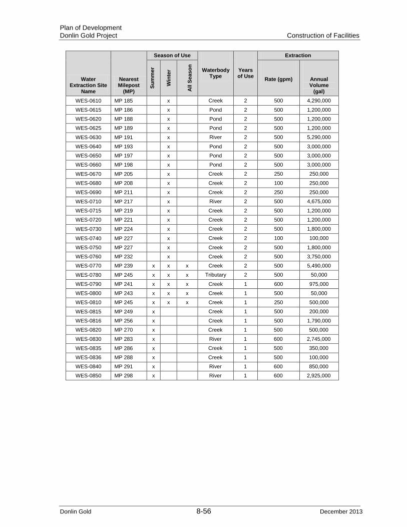
Plan of Development Donlin Gold Project Construction of Facilities
Donlin Gold 8-56 December 2013
Water Extraction Site
Name
Nearest Milepost
(MP)
Season of Use
Waterbody Type
Years of Use
Extraction
Sum
mer
Win
ter
All
Seas
on
Rate (gpm) Annual Volume
(gal)
WES-0610 MP 185 x Creek 2 500 4,290,000
WES-0615 MP 186 x Pond 2 500 1,200,000
WES-0620 MP 188 x Pond 2 500 1,200,000
WES-0625 MP 189 x Pond 2 500 1,200,000
WES-0630 MP 191 x River 2 500 5,290,000
WES-0640 MP 193 x Pond 2 500 3,000,000
WES-0650 MP 197 x Pond 2 500 3,000,000
WES-0660 MP 198 x Pond 2 500 3,000,000
WES-0670 MP 205 x Creek 2 250 250,000
WES-0680 MP 208 x Creek 2 100 250,000
WES-0690 MP 211 x Creek 2 250 250,000
WES-0710 MP 217 x River 2 500 4,675,000
WES-0715 MP 219 x Creek 2 500 1,200,000
WES-0720 MP 221 x Creek 2 500 1,200,000
WES-0730 MP 224 x Creek 2 500 1,800,000
WES-0740 MP 227 x Creek 2 100 100,000
WES-0750 MP 227 x Creek 2 500 1,800,000
WES-0760 MP 232 x Creek 2 500 3,750,000
WES-0770 MP 239 x x x Creek 2 500 5,490,000
WES-0780 MP 245 x x x Tributary 2 500 50,000
WES-0790 MP 241 x x x Creek 1 600 975,000
WES-0800 MP 243 x x x Creek 1 500 50,000
WES-0810 MP 245 x x x Creek 1 250 500,000
WES-0815 MP 249 x Creek 1 500 200,000
WES-0816 MP 256 x Creek 1 500 1,790,000
WES-0820 MP 270 x Creek 1 500 500,000
WES-0830 MP 283 x River 1 600 2,745,000
WES-0835 MP 286 x Creek 1 500 350,000
WES-0836 MP 288 x Creek 1 500 100,000
WES-0840 MP 291 x River 1 600 850,000
WES-0850 MP 298 x River 1 600 2,925,000

Plan of Development Donlin Gold Project Construction of Facilities
Donlin Gold 8-57 December 2013
Table 8-12a: Susitna Valley Winter Access Potential Water Extraction Sites for the Ice Road Construction
Water Extraction Site Name
Nearest Milepost (MP)
Season of Use Waterbody
Type Years of Use
Extraction
Sum
mer
Win
ter
All
Seas
on Rate
(gpm) Annual Volume
(gal)
The following are Susitna Valley Winter Access Potential Extraction Sites for the Ice Road Construction. See Section 8.4.4 and Table 8-8 for additional information of these winter access roads.
WEX-Texas Bear Creek Route x Creek 2 500 1,500,000 WEX-Bear Bear Creek Route x Creek 2 500 2,400,000 WEX-Susitna Big Bend Trail x River 2 500 3,600,000 WEX-Deshka Big Bend Trail x River 2 500 3,600,000 WEX-Fish Big Bend Trail x Creek 2 500 4,200,000 WEX-Yentna-S Big Bend Trail x River 2 500 4,200,000 WEX-Eightmile Oil Well Road Route x Creek 2 500 4,800,000 WEX-Kutna Big Bend Trail x Creek 2 500 2,400,000 WEX-Clear Bear Creek Route x Creek 2 500 2,400,000 WEX-Deep-W Bear Creek Route x Creek 2 500 3,000,000 WEX-Sevenmile-N Deep Creek Route x Creek 2 500 1,800,000 WEX-Twentymile Oil Well Road Route x Slough 2 500 4,800,000 WEX-Yentna-N Oil Well Road Route x River 2 500 4,800,000 WEX-Kahiltna Oil Well Road Route x River 2 500 7,800,000 WEX-Chijuk-E Oil Well Road Route x Tributary 2 500 2,400,000 WEX-Chijuk-W Oil Well Road Route x Tributary 2 500 5,400,000 WEX-Deep-E Alexander Route x Creek 2 500 2,100,000 WEX-Fox Alexander Route x Creek 2 500 2,100,000 WEX-Sevenmile-S Deep Creek Route x Tributary 2 500 2,700,000
Estimated water use requirements with 450-600 gallons per minute rate of withdrawal and drilling cuttings and mud for disposal for HDD operations are shown in Table 8-13.
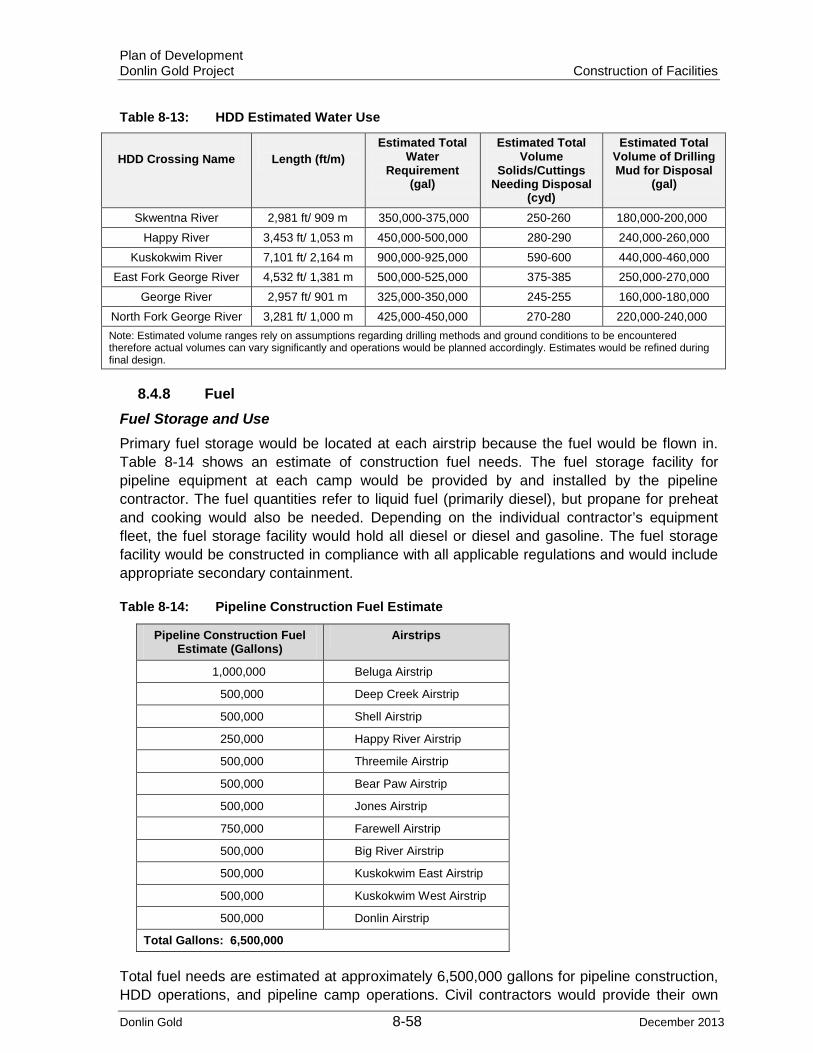
Plan of Development Donlin Gold Project Construction of Facilities
Donlin Gold 8-58 December 2013
Table 8-13: HDD Estimated Water Use
HDD Crossing Name
Length (ft/m)
Estimated Total Water
Requirement (gal)
Estimated Total Volume
Solids/Cuttings Needing Disposal
(cyd)
Estimated Total Volume of Drilling Mud for Disposal
(gal)
Skwentna River 2,981 ft/ 909 m 350,000-375,000 250-260 180,000-200,000 Happy River 3,453 ft/ 1,053 m 450,000-500,000 280-290 240,000-260,000
Kuskokwim River 7,101 ft/ 2,164 m 900,000-925,000 590-600 440,000-460,000 East Fork George River 4,532 ft/ 1,381 m 500,000-525,000 375-385 250,000-270,000
George River 2,957 ft/ 901 m 325,000-350,000 245-255 160,000-180,000 North Fork George River 3,281 ft/ 1,000 m 425,000-450,000 270-280 220,000-240,000 Note: Estimated volume ranges rely on assumptions regarding drilling methods and ground conditions to be encountered therefore actual volumes can vary significantly and operations would be planned accordingly. Estimates would be refined during final design.
8.4.8 Fuel Fuel Storage and Use Primary fuel storage would be located at each airstrip because the fuel would be flown in. Table 8-14 shows an estimate of construction fuel needs. The fuel storage facility for pipeline equipment at each camp would be provided by and installed by the pipeline contractor. The fuel quantities refer to liquid fuel (primarily diesel), but propane for preheat and cooking would also be needed. Depending on the individual contractor’s equipment fleet, the fuel storage facility would hold all diesel or diesel and gasoline. The fuel storage facility would be constructed in compliance with all applicable regulations and would include appropriate secondary containment.
Table 8-14: Pipeline Construction Fuel Estimate
Pipeline Construction Fuel Estimate (Gallons)
Airstrips
1,000,000 Beluga Airstrip
500,000 Deep Creek Airstrip
500,000 Shell Airstrip
250,000 Happy River Airstrip
500,000 Threemile Airstrip
500,000 Bear Paw Airstrip
500,000 Jones Airstrip
750,000 Farewell Airstrip
500,000 Big River Airstrip
500,000 Kuskokwim East Airstrip
500,000 Kuskokwim West Airstrip
500,000 Donlin Airstrip
Total Gallons: 6,500,000
Total fuel needs are estimated at approximately 6,500,000 gallons for pipeline construction, HDD operations, and pipeline camp operations. Civil contractors would provide their own

Plan of Development Donlin Gold Project Construction of Facilities
Donlin Gold 8-59 December 2013
fuel supply for the initial line clearing and associated work. All fuel handling, transportation and storage would be conducted in compliance with all applicable regulations. Fuel would be delivered to the storage site by DC6 or Herc C-130 from bulk fuel suppliers such as Everts or Lynden. It would be necessary to keep about 5 to 7 days’ fuel supply on hand for at least the camp and essential equipment to allow for road closure or slow deliveries because of weather or road conditions. Fuel would be dispensed to the contractor’s fuel trucks for fueling of construction equipment on the ROW or at camp. Pumps at the fuel storage facility can fuel light vehicles and/or on-highway trucks. There would also be a propane storage facility so that contractors can refuel their preheat equipment.
There would be a smaller capacity fuel storage facility closer to the camp facilities for diesel generators and/or for heating oil that would be piped to the camp directly, depending on the type of heating system. A gross estimate of annual fuel consumption would be on the order of 175,000 gallons. The camp may also have its own propane storage tanks for cooking fuel. Camp fuel storage facilities are included in the cost of the camp.
There would also be small, double-walled tanks with drip liners for helicopter refueling. They would be located at the designated helipad.
The pipeline contractor would use the equipment shop and warehouse buildings. Because of the remoteness of the project location, the large amount of equipment, and the winter construction seasons, the contractor would require the weather protection afforded by buildings to perform equipment and vehicle maintenance and overhauls. Buildings and/or van trailers with modular loading docks can be used to store consumables, tools, and parts. The size and number of buildings required would vary, depending on season of work and size of the spread. Fueling would be done at least 100 ft (30 m) from waterbodies.
8.4.9 Barge Landings and Ports
Donlin Gold anticipates the use of ports with ancillary storage yards including the Port of Anchorage, the Port of Bethel, Beluga Landing, Jungjuk Landing, and the construction of barge landings at Kuskokwim East and Kuskokwim West (Table 8-15).
Ancillary support facilities would follow major pipe and equipment staging areas and access roads.
Barge Landing at Jungjuk Port A barge landing at Jungjuk Port on the Kuskokwim River would be developed and used to support pipeline construction and mine development. Construction, operation, maintenance and reclamation of this site would be included as part of developing the mine project.
Barge Landing at Beluga Some improvements to the existing barge landing at Beluga would be required, along with associated construction of laydown yards and a campsite. Specific improvements that are needed would be detailed during final design.
Port of Bethel A laydown yard at the Port of Bethel would be needed for staging pipe and contractor equipment for barging up the Kuskokwim River.

Plan of Development Donlin Gold Project Construction of Facilities
Donlin Gold 8-60 December 2013
Barge landing on east side of the Kuskokwim River A barge landing would be constructed at the pipeline crossing area and would be used for unloading and staging pipe and contractor equipment for construction work in Sections 5, 4, and 3C of Spread 1.
Barge landing on west side of the Kuskokwim River A barge landing would be constructed at the pipeline crossing area and would be used for unloading and staging pipe and contractor equipment for construction work in Section 6 of Spread 1.
Table 8-15: Port Sites and Barge Landings
Spread Served Name Approximate Location 1 Kuskokwim West MP 240 1 Kuskokwim East MP 240 1 Jungjuk Kuskokwim River below
Crooked Creek 1 Port of Bethel Bethel 2 Beluga Landing Beluga 2 Port of Anchorage Anchorage
Use of any of these sites would require negotiations and legal leases or use agreements with the owners/operators, or land owner.
8.5 Pipeline Facilities Installation
8.5.1 Beluga Tie-In to Beluga Pipeline The Donlin Gold proposed pipeline would tie into the BPL portion of natural gas distribution system as the source for the natural gas. The tie-in facility located at MP 0 would consist of a concrete valve vault around the BPL that would house the hot tap and tie-in valve. There would be a small meter module and communications shelter in addition to the associated valving and emergency shutdown valve. There would also be a pig launcher at this location. All structures, with the exception of the valve vault, are planned as pile-supported structures. Refer to Section 6.9 and Figure 6-2 for site plan.
8.5.2 Terminus at Mine Site The meter station at the mine plant site would have a liquids separation vessel (used only during pigging operations), a pig receiver, a meter building, and connection to the communications system at the Donlin Gold mine site. All structures are currently proposed as pile-supported structures. Refer to Section 6.9.
8.5.3 Compressor Station The pipeline would be designed to deliver natural gas to the proposed Donlin Gold mine project at a maximum rate of approximately 73 mmscfd (2.1 million Nm3pd) and at a minimum pressure of 550 psig, although start-up operational demands are projected to be 50 mmscfd (1.4 million Nm3pd). The supply pressure from the tie-in at the BPL ranges from 720 to 800 psig. As the gas flows through the pipeline, the pressure would decrease because of friction. To meet the delivery requirements of 550 psig, one compressor station would be required to boost the gas pressure for delivery to the proposed Donlin Gold mine

Plan of Development Donlin Gold Project Construction of Facilities
Donlin Gold 8-61 December 2013
site. Based on current design, a single compressor station would provide sufficient compression for the gas throughput. The compressor station would be located in the Matanuska-Susitna Borough at MP 0.4. Compressor station components would be modularized to minimize onsite construction and commissioning work in remote locations. To accommodate environmental conditions, the units would be placed inside building modules. Figure 6-1 is a compressor site location map that shows the power transmission line alignment.
The compressor station would have two main components: electrically powered natural gas compression machines and after-coolers provided to reduce gas temperature following the compression process. Additional equipment necessary to support the compression process include systems to prevent overpressure and to provide rate, temperature and pressure control, trouble alarms, ESD, and fire and gas detection systems. The compressor station preliminary electrical design and building siting was developed using the area classification requirements in National Fire Protection Association (NFPA) 70. All other locations along the pipeline requiring electrical power or controls were assumed to be classified areas. The final design of the pipeline and facilities would have complete area classification drawings, and the materials to be procured and installed in the classified areas would meet the requirements of NFPA 70.
Three compressors of approximately 1,000 horsepower (hp) each would be used to deliver natural gas at different rates and pressures, depending on the fuel consumption demands of the mine project. Only two compressors would be required in order to meet current design flow conditions; the third would function as a backup compressor. The foundations for the compressor station modules would be steel piles having a minimum diameter of 12 inches (30.48 cm) and a minimum set depth of 25 ft (8 m). The compressor station location has no permafrost. The workpad would be gravel, have a thickness of approximately 3 ft (0.91 m) and be approximately 240 x 272 ft (73 x 83 m) in plan dimension. The compression station facility site would be approximately 1.5 acres (0.61 ha) and would be unmanned, with fully automated equipment operated by a remote-control system. A 10-foot-high (3 m) chain link fence would surround the site for security. Figure 8-3 shows the compressor station site plan. A permanent road exists along the alignment in the SFSGR which would provide access to the compressor site at approximately MP 0.4. No provisions would be made for short- or long-term human occupancy at the compressor site.
All compression equipment would be powered by electricity. There would be no engines or open flame at the site. Electrical power to the site would be provided by a 25-kilovolt (kV), cross-country power line originating at the 385-megawatt (MW) CEA power plant at Beluga. Because of the reliability of the electrical supply utility, there would be no need for an emergency power generator. However, emergency lighting would be supplied from a dedicated lighting panel located in the power distribution center (PDC) module. Emergency lighting throughout the pad would be connected directly to individual feeder circuits. In addition to the emergency lighting panel, emergency power would be supplied to the programmable logic center control cabinet and communications rack located in the PDC module. The uninterruptible power supply (UPS) (dual rectifiers, battery plant and inverter system) would have a load of approximately 10 kV and would be sized to supply power to the emergency loads for 24 hours. The fire and gas systems are intended to be powered by the UPS system at the compressor station.
The fiber-optic communications cable would be routed to the compressor station along with the buried pipeline and continue to the Donlin Gold mine site with the pipeline.

Plan of Development Donlin Gold Project Construction of Facilities
Donlin Gold 8-62 December 2013
The design provides for continued service at the required delivery rates and pressures with one compressor or one air cooler out of service. Therefore, the design provides at least one spare compressor and one spare air cooler. To meet those criteria and to provide a broad range of flow rate control, the design includes three compressor modules, each rated at 25 mmscfd (0.7 million Nm3pd) and 1,480 psig at 100 F (37.7°C). The system is designed to deliver up to 73 mmscfd (2.1 million Nm3pd) at 1,400-psig discharge pressure with two compressors online and the third as a standby unit. Table 8-16 shows the operating design factors.
Table 8-16: Operating Design Factors for Compressor Station
Parameter Operating Design
Supply Temperature 20°F to 50°F -20°F to 100°F
Supply Pressure 720 to 800 psig 1,480 psig
Discharge Pressure 1,250 psig 1,480 psig
Minimum Destination Pressure 550 psig 550 psig
Flow Rate 47 mmscfd Up to 73.1 mmscfd
The gas would be at soil temperature at burial depth. °F = degrees Fahrenheit mmscfd = million standard cubic feet per day psig = pounds per square inch gauge
The gas compressor(s) would be powered by electric motors that would be fitted with variable frequency drives (VFDs). VFDs provide the ability to adjust the speed of motors and compressors, which correspondingly adjust the flow rate of the natural gas.
Under normal operations, the gas would be piped directly to the compressor modules. The gas would then enter a suction scrubber that would capture any free liquids. Those liquids would be re-injected into the pipeline for handling at the terminus. The gas would then enter the compressors and flow to filter coalescers for removal of lubrication oil that has been carried over from the compressor cylinders. From there, the gas would be processed through an air-cooled heat exchanger (fin-fan) to reduce the gas temperature. The gas would then enter the pipeline and be transported to the Donlin Gold mine site.

FIGURE:SCALE:
DONLIN GOLD PROJECT
8-3COMPRESSOR STATION
SITE PLAN
DG: PER0285.mxd, 10/29/13, R04
NOTES:1. NO PROVISIONS MADE FOR TEMPORARY OR PERMANENT HUMAN OCCUPANCY.
NA
SITE INFORMATIONFENCE LINE: 240'-0" x 272'-0"AREA: APPROX. 1.5 ACRES

Plan of Development Donlin Gold Project Construction of Facilities
Donlin Gold 8-64 December 2013
The compressor station would be designed, installed, operated, and maintained in accordance with the following standards:
• 49 CFR 192 – Transportation of Natural Gas and Other Gas by Pipeline • ASME B31.8 – Gas Transmission and Distribution Piping Systems • All codes and standards referenced and incorporated herein by 49 CFR 192 and
ASME B31.8 • In accordance with 49 CFR 192, all pipe located with the compressor station would
have a design factor of 0.50
Architectural
• Alaska Administrative Code • 2009 International Fire Code • 2009 International Building Code (IBC) • 2009 International Mechanical Code (IMC) • NFPA 72, National Fire Alarm Code, 2010 • NFPA 70; National Electrical Code (NEC) 2011
Civil/Structural
• IBC 2009 • American Institute of Steel Construction Manual of Steel Construction, 13th edition • American Society of Civil Engineers 7-05, Minimum Design Loads for Buildings and
Other Structures • American Welding Society, Structural Welding Code D1.1, 2008 • OSHA Title 29, Parts 1910 and 1926 • American Society of Testing and Materials • American National Standards Institute • ASME B.30 series • API Recommended Practice 2214, Spark Ignition Properties of Hand Tools,
Section 2.2
Mechanical and Piping
• 49 CFR 192 – Transportation of Natural and Other Gas by Pipeline: Minimum Federal Safety Standards
• Material Specification Standard SP-44 – Steel Pipeline Flanges • API 1104 – Welding Pipelines and Related Facilities • API 618 – Reciprocating Compressors for Petroleum, Chemical, and Gas Industry
Services • API 670 – Machinery Protection Systems • ASME B31.8 – Gas Transmission and Distribution Piping Systems • ASME B16.5 – Pipe Flanges and Flanged Fittings • ASME Boiler and Pressure Vessel Code, Section VIII, Division 1 – Rules for the
Construction of Pressure Vessels • ASME Boiler and Pressure Vessel Code, Section VIII, Division 2 – Rules for the
Construction of Pressure Vessels – Alternative Rules

Plan of Development Donlin Gold Project Construction of Facilities
Donlin Gold 8-65 December 2013
• ASME Boiler and Pressure Vessel Code, Section IX – Welding and Brazing Qualifications
IMC 2006
• ASTM A106/A106M-04b – Standard Specification For Seamless Carbon Steel Pipe for High-Temperature Service
• API Specification 6D – Pipeline Valves • SPC-402896-PL-02 – fusion-bonded epoxy (FBE) Coating Application • SPC-402896-PL-03 – abrasion-resistant overcoat (ARO) Coating Application • SPC-402896-PL-04 – Pipe Handling • SPC-402896-PL-07 – Block Valves • SPC-402896-PL-08 – Pipeline Construction • SPC-402896-PL-09 – Non Destructive Testing • DCA – Piping Material Class Specification for 600 ANSI • API 520 Recommended Practices, Part 1, Sizing Selection and Installation of
Pressure Relieving Devices. 8th Edition. December 2008 • API 520 Recommended Practices, Part 2, Sizing Selection and Installation of
Pressure Relieving Devices. 5th Edition. August 2003 • ANSI/API Standard 521, Pressure-relieving and Depressuring Systems. 5th Edition,
January 2007 and Addendum. May 2008 • ASTM Section VIII, Division 1. Boiler and Pressure Vessel Code, 2010 Edition, UG
125-140
Electrical
• NFPA 70: 2011 NEC
• Institute of Electrical and Electronics Engineers, Standard C2, National Electric Safety Code
• NFPA 497: Recommended Practice for the Classification of Flammable Liquids, Gases, or Vapors and of Hazardous (Classified) Locations for Electrical Installations in Chemical Process Areas
• NFPA 780: Installation of Lightning Protection Systems, latest edition • National Electrical Manufacturers Association • Underwriters Laboratories (UL). All equipment would bear the UL label, or
equivalent from a nationally recognized testing agency • Illuminating Engineering Society of North America Lighting Handbook, latest edition • Electronic Industries Alliance/Telecommunications Industry Association 568B
Commercial Telecommunications Wiring Standard • American National Standards Institute • National Electrical Contractors Association. 1-2006 Good Workmanship in Electrical
Construction.
8.5.4 Electric Transmission Line To meet the operational needs of the metering station and the compressor station of an estimated 2.5 MW of electrical power, a medium voltage (MV) aboveground transmission line would be constructed to connect electrical power between the Beluga Power Plant substation and the Compressor Station at MP 0.4, an estimated distance of 8.1 miles (13

Plan of Development Donlin Gold Project Construction of Facilities
Donlin Gold 8-66 December 2013
km). The transmission line would be primary metered by CEA at the substation. From the primary metering point, CEA would install a buried cable to exit the substation property and interface with the owner-constructed overhead MV transmission line. The CEA cable would terminate at the top of the MV transmission line riser pole.
The routing of the MV transmission line would follow the CEA high-voltage transmission line corridor to the BPL tap point within a 30 ft (9 m) easement that Donlin Gold would obtain. At the tap point, which is the start of the Donlin Gold pipeline, a 15-kilovolt-ampere transformer would be mounted to the transmission line to supply utilization-level voltage to a gas-metering module. The transmission line would continue following the pipeline ROW between the pipeline tie-in point at MP 0 and the compressor station located at MP 0.4.
The MV transmission line would approach the compressor station pad along the pipeline ROW just south of the pad. Near the pad edge, the overhead transmission line would terminate with a riser pole. From the riser pole, the incoming power from the Beluga Power Plant would be direct buried in the pad to the PDC module.
Figure 6-1 and Appendix A show the location and land status for the electric transmission line. A portion of the proposed transmission line to power the compressor station crosses private surface estate land owned by CIRI within the Kenai Peninsula Borough. CIRI’s surface estate ownership is in that portion of T13N R10W SM, where the proposed transmission line is located.
8.5.5 Fiber Optic Communication Line As noted in Section 3 of this PoD Donlin Gold is currently evaluating options for where the fiber optic cable would originate, whether from Beluga or elsewhere. From the metering station at the pipeline tie-in to the BPL as shown in Figure 8-4 and Appendix A the fiber optic cable would be buried to the compressor station and then, except at the two fault crossings where the pipeline and cable would be aboveground, on to the Donlin Gold mine site. Details regarding installation of the fiber optic cable would be determined during final design. The sequencing and installation of the pipeline and fiber optic cable must be coordinated to minimize ROW disturbance and to utilize existing pipeline storage sites and the pipeline ROW before they are reclaimed.
The fiber optic cable communications would be used for communication purposes including transmitting data to and from the compressor station, the meter station located at the tie-in point to the BPL, the meter station at the pipeline terminus, and the control center. Authorization to install the fiber optic cable would be applied for separate from the pipeline to allow Donlin Gold communications use options. See Section 6.6 for additional information.
8.5.6 Clean-up and Reclamation After facilities are constructed, ground disturbances would be addressed concurrent with construction or as soon as conditions allow as described in Section 10 and in the Donlin Gold Stabilization, Rehabilitation and Reclamation Plan. In the interim, the areas would be cleaned, stabilized and any necessary erosion control measures implemented.

#*
!.!(
Landing Area/Storage Yard
Beluga Power Plant Substation/Electric Transmission Line & OptionFor Fiber Optic Cable Point of Beginning
Medium Voltage Above Ground Electric Transmission Line Approximately 8.1 Miles To Compressor Station
Donlin Gold Gas PipelineCompressor Station/Electric Transmission LinePoint of Termination at MP 0.4
C O O K I N
L E T
Donlin Gold Gas Pipeline Point of Beginning (MP 0)
Fiber Optic Cable WouldContinue With Pipeline To Mine Site in Buried Mode
Fiber Optic Cable in Buried Mode from MP 0 at Metering Station Tie-in with BPL to Compressor Station
Beluga River
Potential Beluga Construction-Phase Camp Location/Storage Yard
MP-0
MP-1
MP-2
MP-3
MP-4
MP-5
MP-6
MP-7
MP-8
MP-9
MP-10
MP-11
TL-7
TL-6TL-5
TL-4
TL-3
TL-2
TL-1
K
DG: PER0273.mxd, 12/10/13, R11
ELECTRIC TRANSMISSIONLINE AND FIBER OPTIC CABLE
FIGURE:SCALE:
DONLIN GOLD PROJECT8-4
USGS Tyonek Quad 250KSeward Meridian, UTM Zone 5, NAD83
Proposed Transmission Milepost (TL-)
Proposed Gasline Milepost (MP-)
#* Compressor Station
Proposed Natural Gas Pipeline Alingment
Proposed Transmission Line
!. Existing Power Plant
Existing Camp
Existing Storage Yard
0 3 61.5 km
0 2 41 mi

Plan of Development Donlin Gold Project Construction of Facilities
Donlin Gold 8-68 December 2013
8.6 Pipe Installation After the initial clearing and grading, pipeline construction activities would follow a linear sequence of activities (construction mode and sequence typicals are in Appendix G) including the following:
• Stringing • Bending • Welding • Inspection • Coating • Trenching • Bedding • Lowering-in and padding (installation of fiber optic cable prior to backfilling) • Padding and Backfilling • Tie-ins • Pressure testing • Cleanup and reclamation • Pipeline commissioning
Specific construction practices and sequencing may vary with construction season, and terrain type. The various ROW construction modes are depicted in the typicals in Appendix G. Specialized equipment required for construction is shown in the exhibits in Appendix G. Specialized equipment for winter construction includes low-ground-pressure track equipment for use in moving equipment and materials.
8.6.1 Areas Requiring Blasting The need for blasting during project construction would be determined during final design. A Blasting Plan would be developed and would apply in all situations where blasting occurs including material borrow sites. Blasting in proximity to structures would be unlikely because of the remote location of the proposed project.
Specifications for both ROW grade and trench blasting would be included in the construction documents and require that the contractor prepare detailed blasting procedures for approval by Donlin Gold before conducting any blasting.
All blasting would conform to the rules and regulations of OSHA and of all other relevant federal, state, and local agencies. Federal regulations that apply include, but are not limited to, the following:
• 27 CFR 181 – Commerce in Explosives • 49 CFR 177 – Carriage by Public Highway • 29 CFR 1926.900 et seq., Subpart U – Safety and Health Regulations for
Constructions – Blasting and Use of Explosives • 29 CFR 1910.109 – Explosives and Blasting Agents OSHA.

Plan of Development Donlin Gold Project Construction of Facilities
Donlin Gold 8-69 December 2013
8.6.2 Stringing Pipe would be loaded onto stringing trucks in the PSYs using an excavator equipped with a
vacuum lift. The PSYs are laid out approximately every 5 miles (8 km). The stringing crew would include operators, truck drivers, and laborers. This crew is sized to match the lay rates to stay ahead of the pipe gang and MLV crews.
The pipe would be unloaded from trucks on the ROW by a CAT 561 or 572-class sideboom and set down on a skid at each end. If the stringing trucks cannot easily traverse the ROW because of terrain or other factors, then one or two D7 or D8 winch CATs can be used to assist. On very steep hills, the sideboom must meet the stringing truck at the closest point of access and pack each joint one at a time down the ROW. On hills so steep that the pipe would not stay in place, each joint would be moved individually up or down to the pipe gang from a stockpile on the ROW. There may be several hills in Section 6 with this degree of steepness.
Another important function of a stringing crew is to work pups (sections of short pipe) back into the line. On this project, any pups longer than about 12 ft (3.6 m) would be required to be welded into the line. Such pups are often used by the bending engineer to shift the location of bends relative to girth welds. The stringing crew would work with the bending engineer to deliver pups ahead in the stringing sequence so that they can be welded by the pipe gang. The stringing crew would also distribute skids for pipe stringing, setup, and cribbing the pipe. A skid truck would drop the skids just ahead of pipe stringing. Because of the possibility of blowing snow burying the skids, stringing of skids cannot proceed too far in front in winter. After the pipe is placed in the trench, the skids would be picked up and reused in subsequent sections.
The stringing crew would have a skid truck and a sufficient number of laborers for working pups. The stringing crew would also deliver materials such as valves, fittings, and induction bends to the ROW and MLV sites at the appropriate time.
Each individual joint of pipe would be unloaded with equipment and placed (strung) near the pipeline centerline. This operation may be conducted before, during, or just after trench excavation. Pipe for waterbody crossings would be stockpiled at temporary staging areas near crossings so that sufficient lengths are available to install the crossing. Large amounts of pipe staging would be required for the HDD installations, which would be laid out in the pullback staging areas. Care must be taken during the stringing process not to damage pipe coating because all nicks or gouges in the coating must be repaired before placement of pipe in the trench.
Mainline pipe would be coated at the point of manufacture to provide high quality coating under tightly controlled conditions and to provide corrosion protection for the pipe during barge shipment to Alaska. Pipe would be handled in a manner that would prevent damage to pipe walls, pipe ends, coating, and insulation.
Stringing operations would be coordinated with all other installation activities so that pipe is available for bending, welding, and lowering in order to minimize the amount of time the trench is open. The intent is to close the trench as soon as practical. The pipeline construction plan calls for minimization of open trench for construction purposes. The more time a trench is open, the higher the chance of the trench filling with snow and having to do snow removal from an open trench.

Plan of Development Donlin Gold Project Construction of Facilities
Donlin Gold 8-70 December 2013
8.6.3 Bending and Set-up Before the joints of pipe have been welded together, they are strung along the trench then individual joints would be bent to accommodate horizontal and vertical changes in direction to match the excavated trench. Field bends would be cold-formed using a hydraulically operated bending machine. Where the required magnitude of a bend exceeds the allowable limits for a field-bent pipe, factory (induction) bends would be installed.
When the trench is being excavated before stringing, a bending engineer and one or two helpers would measure every joint of pipe on the ROW and survey the trench for grade and the sidebends for angle of bend. The engineer would calculate the degree of bend for every sagbend, overbend, sidebend and combination bend. The location of every bend would be marked on the appropriate joint of pipe.
Because much of this project would be constructed in winter, the contractor may elect to trench after the pipe is bent. This would mean that the trench would have to be dug to fit the bent pipe. The bending engineer would work off the profiles and plans on the alignment sheets and would survey the original ground. From that information and knowing the depth of cover, the bending engineer can calculate the bends. The trenching crew would make sure that sags, overbends, sidebends, and combinations are dug in the correct location to match the pipe.
Two hydraulic pipe-bending machines per spread would be used to bend pipe joints on the ROW to conform to the contours of the trench bottom and directional changes in the alignment. One bending machine would be used ahead of the main welding crew; a second may be used for yard bending before stringing. There would be a spare hydraulic mandrel on each spread. Two sidebooms would work with each bending machine, bringing pipe to be bent, catching the pipe as it is run through the bender, and returning the pipe to its skids for setup. All joints, straight or bent, would be set up and aligned properly for the welding crews. One of the sidebooms would tow the bending machine down the ROW when it needs to be moved.
Induction bends may also be used on the pipeline for sharp side bends, launcher/receiver assemblies, and sharp sag bends at incised stream crossings, and at other locations. The number of induction bends needed can be determined after detailed design.
8.6.4 Lineup and Welding After pipe joints have been bent, they would be lined up end-to-end and clamped into
position. The joints would then be welded together in conformance with 49 CFR 192, Subpart E (Welding of Steel in Pipelines). Automatic welding machines may be employed for this process, but it is envisioned that the majority of the welding for a pipeline of this diameter would be stick welding. All crews would have fire prevention equipment with them on site.
A manual gas metal arc welding (GMAW) process is planned for welding the mainline pipe. This welding would begin with proper bevel preparation by buffing with a grinder to remove burrs or oxidation on both ends of each joint. The joints would be spaced and lined up, using internal lineup clamps controlled by an 80-foot (24 m) reach rod. The two bead welders would work together using the GMAW process. Each welder would start at the top of pipe and weld downhill on one-half of the pipe meeting at the bottom. As the bead is finished, the
Plan of Development Donlin Gold Project Construction of Facilities
Donlin Gold 8-71 December 2013
internal clamps would be released and moved forward for the next space and lineup so that the bead welders can proceed from the finished bead to the next joint and repeat the process.
The remaining external passes (the hot pass, then the fill passes, and, finally, a cap pass) would be made by three or four pairs of welders in the firing line crew, one on each side of the pipe. This process is typical of traditional stick welding technology. The mainline lineup and welding crews (pipe gang and firing line) would have about 50 workers total, with 30 in the pipe gang and the balance in the firing line. These two crews would weld long, continuous strings of mainline pipe, including drag sections for river crossings and HDDs.
The weld rates would vary, depending on terrain and season. If the terrain is flat, lay rates would be higher.
8.6.5 Inspection (Nondestructive Examination) All welds would be visually inspected by an American Welding Society (AWS) certified inspector who is part of the construction management staff or execution contractor quality control staff. Non-destructive radiographic or ultrasonic inspection methods would be used, in accordance with USDOT requirements. The percentage of welds that are inspected would comply with requirements of 49 CFR 192.243, Welds: Nondestructive Testing. Any defects would be repaired or cut out as required under the specified regulations and standards. Documents that verify the integrity of the pipeline would be kept on file by Donlin Gold for inspection by the USDOT Office of Pipeline Safety.
8.6.6 Field Joint Coating To prevent corrosion, the majority of the pipe would be externally coated with a three-layer polyethylene coating before delivery. The pipe intended for HDD installation would use a fusion bonded epoxy (FBE) corrosion-prevention coating, and finished with an abrasion Resistant Overlay (ARO). After welding, field joints would be coated with a shrinkable sleeve wrap, or field-applied liquid epoxy. Before the pipe is lowered into the trench, (or pulled back into an HDD) the coating would be visually inspected and tested with an electronic detector for coating defects. Any defects or scratches (holidays) would be repaired and re-inspected before the pipe is lowered into the trench.
Following acceptance of the weld, the weld joint would be sandblasted to the required profile by laborers in the coating crew using a compressor and sandblast pot. The construction plan assumes application of shrink sleeves to coat weld joints. Preheat of pipe is required, followed by application of a wraparound sleeve and closure that is shrunk to the pipe by applying propane torch heat to the sleeve.
Detection of holidays or damage caused to the anti-corrosion coating would be performed by passing a holiday detector (jeep), the crest voltage of which would be adjusted in accordance with the type of coating used on the pipe. After holidays have been detected, all defects would be repaired and retested.
8.6.7 Trenching Trenching can begin once the ROW has been cleared and grading operations have been
completed so that trenching equipment can operate on the ROW. Depending on the season and the preference of the construction contractor, trenching would likely begin after all pipe
Plan of Development Donlin Gold Project Construction of Facilities
Donlin Gold 8-72 December 2013
work (bending, welding, coating, and inspection) has been completed. This would minimize the amount of trench that would be open and exposed to winter weather (such as snow, which would have to be removed before installation of pipe).
The trench would be excavated using chain trenchers, wheel trenchers, or backhoes. Chain trenchers perform best in bedrock, or finer-grained, thawed and frozen soils. They do not perform well in abrasive and coarse gravels. Wheel trenchers perform well in unfrozen, cohesive soils that would maintain vertical trench walls. It is believed that there is not enough of the proper soil type in the project area to use wheel trenchers, but field trials before construction could make this determination. Backhoes would be used to excavate the trench where trenchers would not perform well. Backhoes are included for use by the composite trench crews and to excavate around sidebends and tie-in bell holes where the trenches would intersect. Crews would be equipped with both backhoes and trenchers to provide the technique best suited for each soil type.
Trenching crews would excavate a trench deep enough to provide the design soil cover depth over the top of the pipe. This would nominally be 3 ft (0.9 m) of cover over the top of the pipe in soil conditions and 30 inches (76 cm) of cover in rock trench areas. Construction methods used to excavate a trench would vary, depending on soils type and terrain. Excavators would generally be used in areas of steep slopes, high water table, soils with cobbles and boulders, or deep trench areas (river and stream crossings).
Trench width would vary, depending on what piece of equipment is being used for excavation, but generally, trench width would be approximately 18 to 30 inches (46 to 76 cm) wide to allow for placement of pipe and backfill without excavating more material than necessary. In areas of deeper trench excavation (river and stream crossings), trench width at the ground surface may be wider because of sloughing action of soils in high groundwater tables. If it became necessary, sedimentation could be controlled during trenching dewatering with the use of sedimentation basins, geofabrics, and silt fences. Trench plugs would be installed to prevent excessive groundwater flow through the trench in sloping areas.
In areas where significant organic surface material is present, efforts would be made to separate this material from mineral soils during excavation of the trench and to stockpile it separately for use in final cover and reclamation of the trench line after pipe installation.
Excavated mineral soil would be stored separately from windrowed, organic spoil piles. Subsoil would not be stored in flowing waterbodies, dry drainages, or washes that cross the ROW. Subsoil would be placed on the banks of the drainage in such a manner as to prevent sedimentation from occurring, or placed in another location. Gaps would be left periodically in the subsoil piles to prevent ponding and excess diversion of natural runoff during storm events during the summer construction season.
Chain trenchers would excavate approximately 180 miles (290 km) of trench. In most terrain, a composite trenching crew would use both types of equipment. A provision for rock hammering the bottom of the trench is provided for 4,884 linear feet (1,489 m) in Section 6.
The intent is to close the trench as soon as practical. The pipeline construction plan calls for minimization of open trench for construction purposes. The more time a trench is open, the higher the chance of the trench filling with snow and having to do snow removal from an open trench. The construction plan calls for making no more trench than can be filled with

Plan of Development Donlin Gold Project Construction of Facilities
Donlin Gold 8-73 December 2013
pipe and backfilled in a single day. There would be some open trench at the end of the construction day, but it would normally be measured in a few hundred feet during normal construction operations. The construction plan also calls for the majority of the construction spread to maintain close proximity as the pipeline is constructed; in most cases during normal construction operations any open trench would have construction equipment and some human activity in the vicinity of the open trench.
8.6.8 Bedding If necessary, the trench bottom would be cleaned by removing frozen chunks of soil, rocks, and snow. With stable, frozen, trench walls expected in the winter sections, snow removal would be an issue, rather than sloughing of trench walls. In summer, sloughing may be an issue in certain locations, but is not expected to be an issue in Section 6. Specific concerns and locations would be identified during final design.
Bedding would be used only in certain circumstances. In winter, the trench bottom would be bedded for pipe protection purposes when the trench is in bedrock, coarse gravels, or soils with cobbles. The trench would not be bedded when the soil is fine-grained permafrost (even if it is ice-rich); the pipe would be lowered in directly on the trench bottom. In summer, bedding would be used in trenches with jagged bedrock (not expected in Section 6), cobbles, or coarse gravels. The trench would be bedded to a depth of 6 inches (15 cm) with bedding/padding material. All material used for bedding or backfill around pipe would be non-corrosive to pipe.
If the bedding material is produced at a material site, it must be hauled to the ROW and placed in the trench bottom. There would be a loader at the material site, belly dumps, and a loader on the ROW. The output conveyor of a self-propelled padding machine may be adapted to move the material over the pipe. It is assumed that bedding and padding would be produced from the trench spoil, except in certain ice-rich soils where imported bedding and padding is required. The trench spoil bedding crew would include a small bulldozer, three backhoes, a grader, and a padding machine.
8.6.9 Lowering In The lowering-in crew would conduct the holiday detection testing of the continuous pipe string coating system as the pipe is being lifted off the skids and roped into the trench. Any holidays detected would be repaired. The lowering-in crew would have three sidebooms and two backhoes to lower the pipe into the trench. Rollicradles would be used to rope the pipe into the trench. It is assumed that this crew would also make one tie-in weld per day, either on the bank or in the trench.
Trench dewatering may be necessary before and during lowering-in at floodplains and wetlands to prevent the pipe from floating and to perform tie-in welds.
Before the pipe section is lowered into the trench, inspection would be conducted to verify that the trench bottom is free of rocks and other debris that could damage the external pipe coating. Dewatering may be necessary where water has accumulated in the trench and would occur in accordance with permit requirements. Sideboom tractors would be used to simultaneously lift the pipe section, position it over the trench, and lower it in place. Specialized padding (soil screening equipment) machines may be used to screen previously excavated mineral soils to provide a padding and bedding material free of larger material

Plan of Development Donlin Gold Project Construction of Facilities
Donlin Gold 8-74 December 2013
(greater than1 inch in size) to line the bottom of the trench before lowering in and provide backfill material next to the sides and the top of the pipe that would not damage the pipe coating. The coating would be inspected again just before the pipe is placed in the trench.
8.6.10 Buoyancy Control The 0.375-inch (0.9 cm) WT pipe was selected for areas requiring buoyancy control; it would not be necessary to weight the pipeline using set-on weights or continuous concrete coating.
8.6.11 Trench Breakers Trench breaker placement must be coordinated with the padding and backfill, so that the pipe is not padded or backfilled where there needs to be a trench breaker. Trench breakers are installed to slow the flow of subsurface water in the backfilled trench.
Trench breakers, padding, and backfill would be installed by one crew because it is very important during winter construction that the pipe be backfilled as quickly as possible. Trench breakers must be installed before the pipe is padded. Padding and backfill can be combined into one operation so that they are coordinated properly.
Trench breakers would be constructed from foam. Foam would be sprayed into the trench and around the pipe and would expand to fill voids and make a tight seal against the trench wall.
Sandbags are sometimes used to construct trench breakers. They would not be practical for this project because of the narrow trench and very cold temperatures. Frozen sandbags would not conform to the pipe or trench wall. The sandbag trench breakers require laborers to be in the trench, which may not always be possible because of safety concerns.
8.6.12 Padding As trench breakers are installed, the pipe would be padded and then backfilled. The padding material would be produced in one of the following ways:
• Processed from spoil or ROW material by a padding machine • Used as is from trench spoil or taken from the adjacent ROW • Mined as pit run material and hauled to the ROW • Crushed and screened at a material site and hauled to the ROW • Approximately 60,000 yd3 (45,873 m3) of bedding and padding would be produced,
hauled from material sites to the ROW, and placed under (bedding) and around (padding) the pipeline in the trench. A final estimate would be determined during final design. All material used for bedding or backfill around pipe would be non-corrosive to pipe. No bedding would be used for ice-rich soils.
The plan does not include the installation of rock shield. The use of rock shield is not common in the pipeline industry because of its high cost and the amount of labor required for installation.
8.6.13 Backfill Backfilling would begin after a section of pipe has been successfully placed in the trench. All material used for bedding or backfill around the pipe would be tested to ensure that it would be non-corrosive to pipe. Before backfilling the trench, the equipment operator and the
Plan of Development Donlin Gold Project Construction of Facilities
Donlin Gold 8-75 December 2013
construction inspector would check the trench for foreign objects and would have any deleterious material, snow, or ice removed before backfilling begins.
The intent of the backfilling operation during winter seasons would be to immediately backfill where pipe has been lowered in. The only pipe not backfilled during typical installations is the length of pipe required to be exposed to successfully make a tie-in weld to the next section of pipe to be installed in the trench.
Backfilling would generally use the subsoil previously excavated from the trench except where the bottom of the trench is rocky. Imported select fill material may be needed. Backfill would be placed and nominally compacted. Compaction would be performed to the extent that there are no voids in the trench. The backfill would be mounded over the top of the trench to account for settlement of fill so that a depression does not form over the top of the pipe. Mounding would also direct surface water flow away from the trench line. Trench breakers would be constructed as needed to prevent soil migration from longitudinal flow of water along the buried pipe. Where appropriate, dewatering by pumping would be used to remove water flow in the trench. Any water removed from the trench would be discharged in accordance with applicable permits. Any excavated materials unfit for backfill would be spread on the non-traffic side of the ROW. Large rocks from excavated material would be placed in the non-traffic side of the ROW, placed in locations designated in cooperation with the appropriate agency or land owner to create habitat or placed at locations for other purposes. Donlin Gold understands the importance of properly backfilling the trench after the pipe has been placed in the trench. Stabilization of the backfilled trench may be a multi-year process in some areas, particularly areas with fine-grained, ice-rich soils and wetlands if not successfully addressed in design engineering, construction installation and reclamation. If not properly addressed, the proposed pipeline trench may intercept overland flow and change flow patterns that could erode backfill material from the pipeline trench and could potentially serve to channel water into nearby waterways and wetlands. Some areas may be covered with geofabric or other material to prevent erosion. At disturbed areas where the vegetated material is not available, the surface would be prepared for natural revegetation or seeded with native species at the earliest opportunity to minimize erosion and siltation. The techniques that would be used to stabilize rivers and streambanks at pipeline crossings would be determined on a site-specific basis. These may include the use of gravel blankets, riprap, gabions, and geosynthetics.
8.6.14 Tie-ins Tie-in welds would be made in the trench for the lowered-in pipe strings at sidebends and laps. The types of tie-in welds would include stream and river crossings, mainline valves, the laps at sidebends or significant overbends and sags, and any other loose ends or sections.
8.6.15 Waterbody and Wetland Crossings Waterbodies are any natural or artificial drainage, stream, or river with perceptible flow at
the time of crossing construction and other permanent bodies of water such as ponds or lakes. During winter construction, many waterbodies would be frozen solid. Crossings at these locations would be designed for depth of cover, buoyancy control, and restoration of banks, but, technically, these would not be considered waterbody crossings. This would be the case with many small streams in winter sections. With approximately 67% of the route being crossed in winter, the complexity and number of waterbody crossings are reduced.

Plan of Development Donlin Gold Project Construction of Facilities
Donlin Gold 8-76 December 2013
Appendices D and E summarize stream crossings and methods of stream crossing along the pipeline route. This information includes assumed width, depth of scour, and crossing method.
Waterbody Crossings Waterbody crossings are identified in Appendices A and D.
The total linear feet for all open cut waterbody crossings would be determined during final design. Six of the major river crossings are proposed as HDD crossings. All the other streams are planned as open-cut crossings. No aerial crossings are planned.
A significant number of stream crossings would contain fish. Fish streams would be classified as to resident species, quality of habitat, and appropriate mitigation measures would be implemented prior to and during construction and reclamation. The ADF&G has pointed out the importance of high value drainages and streams for fish spawning and has asked that pipeline construction activities, including silt mitigation techniques, around fish streams and rivers be coordinated with them to minimize impacts to fish. Donlin Gold would continue to work with ADF&G to address fish and habitat concerns in crossing streams and rivers.
Streams that would be crossed by the pipeline on the proposed route are shown in Appendix D. Although avoiding construction in salmon spawning streams during sensitive periods is a primary means to protect fishery resources, construction of the gas pipeline project would require crossing of fish streams during the sensitive periods, including winter. There are a number of stream-crossing techniques that can be used to protect fishery resources during sensitive periods. These techniques attempt to isolate the in-water work area from the flowing water of the stream being crossed and include those measures listed below.
• HDD beneath large rivers and critical fish habitat • Damming and pumping streams around crossing sites • Diverting streams to dewater crossing sites • Crossing when streams are completely frozen • Fluming streams through temporary culverts and placing the pipeline beneath the
culverts • Surveying for fish overwintering areas and avoidance of these locations.
The method of open cut would be determined during final design and confirmed at the time of construction. Installation would be monitored by construction and environmental monitors and inspectors during construction, and consistent with the Surveillance and Monitoring Plan following construction. The following six locations also shown in Table 8-4 are currently proposed for HDD crossings:
• Skwentna River (Approximately MP 50) – 2,981 ft (909 m) • Happy River (Approximately MP 86) – 3,453 ft (1,053 m) • Kuskokwim River (Approximately MP 240) – 7,101 ft (2,164 m) • East Fork George River (Approximately MP 283) – 4,532 ft (1,381 m) • George River (Approximately MP 290) – 2,957 ft (901 m) • North Fork George River (Approximately MP 298) – 3,281 ft (1,000 m)

Plan of Development Donlin Gold Project Construction of Facilities
Donlin Gold 8-77 December 2013
Additional crossings are planned as open cuts, some of which may be considered for HDD as would be determined during final design. Additional constraints associated with fish habitat and/or permitting stipulations could also affect the final determination.
HDD pipeline installations would be accomplished in three stages:
1. Drilling a pilot hole along a designed directional path 2. Enlarging or reaming the hole to allow installation of the pipe 3. Pulling the pipe section through the enlarged hole to complete the installation
Note: Installation of the fiber optic cable in relation to pipe installation would be determined during final design and engineering. Timing and coordination of the FOC installation with pipeline construction would be important to reduce ground disturbance and resource impacts and to utilize pipeline crossings at the same time where feasible and prudent to do so.
Three HDDs are planned for summer (the three George Rivers), and three for winter (Kuskokwim River, Skwentna River, and Happy River). All are planned in the same season with the pipe lay adjacent to them. W 2 and S 2.5 are available in the schedule to re-attempt any failed crossings, allowing for another try or use of a different method. This plan would require two large and one medium-sized HDD rigs at the same time on the project, and, possibly, an additional, smaller rig for use on the shorter crossings. HDD equipment would be cleaned prior to entering the project area as required under the Invasive Species Prevention and Management Plan.
The HDD crew would have support personnel for the HDD subcontractor. There would also be an HDD pull-in crew that has the sidebooms and rollers needed to lift the pipe during pullback.
Typical stream crossing methods are shown in Appendix E and are discussed below; except for the HDD method which is discussed above.
A Drilling Mud Disposal Plan would be prepared as part of the overall HDD Practices, Contingency and Resource Protection Plan prior to work taking place on any stream crossing where HDD would be used.
Open-cut Method In general, the open-cut method would be used for three different types of waterbodies. This would be the preferred method for the crossing of the following:
• Intermittent streams, ditches, and non-sensitive waterbodies where sedimentation is not a significant factor.
• Frozen rivers or streams in winter that have no surface flow. A large number of streams that would be crossed in winter will fit this category. Even a river as large as the Big River may be frozen solid in February.
• Streams and rivers that are so large that no isolation method can be used. The open-cut method would be preferred for larger streams and rivers, depending on several factors including the crossing season, flow volume, water velocity, type of bed material or substrate, width, depth, amount of cover, type, and extent of buoyancy control.
- The South Fork of the Kuskokwim River would be a winter open-cut and the Tatina River would be open-cut during the July-August timeframe
Plan of Development Donlin Gold Project Construction of Facilities
Donlin Gold 8-78 December 2013
- The crossings of the Big River, the Middle Fork of the Kuskokwim River, Windy Fork, Sheep Creek, and Tatlawiksuk River would be by winter open cut
For larger rivers, the trench would be excavated through the waterbody, using backhoes operating from the banks, or within the waterbody if it is too wide. For wide, braided rivers, backhoe operators would have to install some channel diversion to give themselves places to work.
Spoil from intermittent streams, trenches, and non-sensitive waterbodies would be placed at least 10 ft (3 m) from the water's edge on the construction ROW or in the extra workspace. The spoil would be contained as necessary by silt fence. A tie-in crew would be used to execute open cuts on intermittent or small streams.
For water bodies other than non-flowing streams or drainage ditches, a trench plug would be left between the upland trench and the in-stream activities to prevent diversion of water into upland portions of the pipeline trench and to keep accumulated trench water out of the waterbody. The trench plug would be removed to allow installation of pipe.
Dam-and-pump Method The dam-and-pump method is a dry crossing method that is suitable for low-flow streams that have a streambed contour suitable for dam installation. The dam-and-pump method is high cost and has severe limitations for use in winter because discharge hoses would freeze; reducing, or shutting down pump output.
The dam-and-pump method involves damming the stream with sandbags or water bladders upstream and downstream of the proposed crossing before excavation and pumping water around the construction area.
Pumping the waterbody across the ROW would begin simultaneously with dam construction to prevent interruption of downstream flow. Waterbody flow would be pumped across the construction area through hoses and would be discharged onto an energy-dissipation device where required to prevent scouring of the streambed.
Some streams or rivers that have low flows in the winter are candidates for dam-and-pump. No specific dam-and-pump crossings have been identified.
Flume Method The flume method would be suitable for crossing sensitive, relatively narrow waterbodies that have straight channels and are relatively free of large rocks and bedrock at the point of crossing. The flume method would not be appropriate for wide or heavily flowing streams. This method involves placement of flume pipes in the waterbody bed to convey water flow across the construction area, isolating the stream flow from the trench water.
Flumes would be selected with sufficient diameter to transport the maximum flows anticipated at the respective crossings. The flumes, typically 40 to 60 ft (12 to 18 m) in length, would be installed before trenching and would be aligned so as not to impound water upstream of the flumes. The flumes would not be removed until after the trench has been dug, the pipeline has been installed, and the trench has been backfilled.
The upstream and downstream ends of the flumes would be incorporated into dams made of sandbags and plastic sheeting (or other suitable material). The upstream dam would be constructed first and would funnel stream flow into the flumes. The downstream dam would

Plan of Development Donlin Gold Project Construction of Facilities
Donlin Gold 8-79 December 2013
prevent backwash of water into the trench and construction work area. The dams would be monitored and adjusted to minimize leakage.
After the flume has been installed and is functioning properly, backhoes located on one or both streambanks (or within the streambed itself if it is too wide) would excavate the trench. Spoil from the stream or riverbed and banks would be placed at least 10 ft (3 m) from the water’s edge or in the extra workspace. The spoil would be contained as necessary by a silt fence.
Standing water that is isolated in the construction area by the dams or any water that leaks through the dams or seeps from the ground into the trench during construction would be pumped to an area in a manner designed to prevent the flow of heavily silt-laden water back into the stream. Sediment control devices would be used as necessary at the outlets of trench pumps.
After the trench has been excavated, the pipe would be installed. There may be some crossings where the pipe section would be short and straight enough for it to be pulled or lowered in under the flume. However, there would be many crossings where the sagbends on the crossing pipe or the length and weight of the pipe would require the flume to be pulled temporarily. In such cases, the flume would be reinstalled as soon as the pipe is in place.
This is a very common method for waterbody crossing installation; however, the route would not include many rivers with characteristics that favor the use of this method. The Tatlawiksuk River is one possibility. In winter, this method can be used on large rivers that have very low flow. In summer, its use would be limited to small streams.
Channel Diversion The channel diversion method diverts a stream or river from its natural channel to a temporary channel excavated for that purpose. It can also involve diverting a stream or river flow into another natural stream channel. This can be accomplished by constructing dams both upstream and downstream of the pipeline crossing area in the waterbody to cause the flow to be diverted through the temporary diversion channel. Excavation and pipe installation can then proceed across the natural channel while being isolated from the flow. After the pipe has been backfilled and the banks have been restored and protected as required, the dams would be removed, while the ends of the diversion channel are simultaneously being backfilled to allow the flow to return to the original channel. This method requires suitable flat terrain adjacent to the stream or river. Diverting flow into a newly excavated channel would produce some sedimentation. Use of a natural channel is preferable.
Wetland Crossings The method of pipeline construction to be used in wetlands and the required width of the construction ROW would depend on the season, the presence or absence of permafrost, the classification of the wetland, access, and environmental conditions at the time.
There would be three basic approaches to crossing wetlands. The most common method would be winter construction, but some summer crossing of wetlands will be required. These may be crossed using a gravel fill workpad or using temporary workpad over geotextile, or another method of separation that would supplement the pad.

Plan of Development Donlin Gold Project Construction of Facilities
Donlin Gold 8-80 December 2013
In winter, wetlands that are underlain by permafrost would be crossed using an ice or snow pad (portions of Sections 3A, 4, and 5). Wetlands without permafrost would be frost packed to freeze them down to more competent soils or deep enough to support the pipe and construction equipment (Sections 1 and 2). There may also be wetlands with a deep active layer that would be frost packed because the active layer does not need an ice pad. For winter construction, the wetland would be frozen, and ice and snow pads would minimize damage, so the width of the ROW need not be constricted through these areas. In deep wetlands or in mild winters, it may be necessary to place timber corduroy or mats in the wetland, even in winter, to support the pipe and/or equipment. Winter matting would be used for warm or short winters.
Winter construction is assumed for a majority of the route. There are approximately 214.8 miles (345.7 km) scheduled for construction in winter and approximately 103.2 miles (166 km) in summer. Therefore, approximately 68% of the route would be constructed in winter, which would reduce the potential for impact to wetlands.
For summer wetlands without permafrost, workpads can be temporary. They would be made from imported fill and/or trench spoil (if suitable) or timber mats. A layer of geotextile or mats would be used to separate fill from vegetation. The width of a construction ROW across a wetland would depend entirely on the season, ROW mode, and access to the ends, trench depth, and related factors. In winter, in a treeless wetland that has an ice pad or is frost packed, the width of the ROW would normally be 100 ft (30 m). In summer, where a gravel pad is installed to protect the permafrost, the ROW may be about 100 ft (30 m) wide if there is good access on both sides. If there is a summer wetland with good access on both sides that must be matted, then the ROW width could be as narrow as 85 ft (26 m), depending on depth and spoil pile size.
Vegetation within wetlands would be cut to ground level, and stump removal would be restricted to the trench line, except where necessary to maintain safety. The upper 12 inches (30 cm) of organic material would be segregated from the area to be disturbed by the trench except in winter.
In winter, no sediment barriers would be necessary at wetland boundaries or along the edge of the ROW or spoil piles. In summer, sediment barriers would be installed immediately upslope of wetland boundaries as necessary to prevent sediment flow into the wetland. Where the ROW is located through or adjacent to wetlands, sediment barriers would be installed along the edge of the ROW to contain spoil and sediment within the ROW as needed.
In winter, temporary workspace setbacks would not be necessary and can be limited to 10 ft (3 m). Sometimes it would be necessary to have temporary extra workspace for a river crossing located in the adjacent wetland.
In summer, extra temporary workspaces would generally be set back at least 50 ft (15 m) from the edge of delineated wetlands where topographic conditions permit. However, where riparian wetlands are adjacent to waterbodies, it may be necessary to place workspace for the waterbody crossing within the adjacent wetland.
After the pipeline has been lowered into the trench, the trench would be backfilled with excavated trench spoil. A permanent slope breaker and trench breaker would be installed at

Plan of Development Donlin Gold Project Construction of Facilities
Donlin Gold 8-81 December 2013
the boundary to the wetland. Trench breakers would also be used to prevent the pipeline trench from draining a wetland and as necessary to maintain the original wetland hydrology.
Waterbody Approaches There would be different clearing, grading, setback, and erosion control methods,
depending on the waterbody and crossing season.
In winter, there would be no need to wait until the time of crossing construction to do clearing. The crossing approach can be cleared at the same time as the adjoining ROW. The grading of the ROW to the crossing would also be done at the same time as the adjoining ROW. There would generally be no need for temporary erosion control structures in winter. In summer, the grading crew would install the crossings to allow access for the heavy equipment, but the pipeline approaches to waterbodies would be cleared and graded just prior to the installation of the crossing.
Because of the nature of stream dynamics monitoring of reclamation of riparian areas would be included in the Surveillance and Monitoring Plan as well as the Stabilization, Rehabilitation, and Reclamation Plan.
Equipment Crossing To allow the passage of equipment along the ROW, waterbodies would be bridged
temporarily by a variety of means, depending on the season, channel width, and environmental considerations. Equipment crossings would be temporary and generally be installed during clearing by the civil contractor and left for use by the pipeline contractor. The crossings would have to support all construction equipment. If a crossing is unable to support a particularly heavy piece, then that piece would have to be lightened to negotiate the crossing. All temporary crossings including culverts and bridging would be taken out and removed once the pipeline construction is complete.
In winter, many drainages and streams would be frozen to the bottom, and the equipment crossing would use the frozen stream as is. Other streams and rivers may be frozen over, but the ice would not be thick enough to support equipment. The ice on these rivers would be thickened to allow equipment to cross. In some cases, ice bridges would need to be reinforced with mats or used in conjunction with bridge sections. Culverts can be used for stream or river crossings only if they do not freeze. It would be important to avoid situations in which ice bridges settle so far into the water that flowing water is diverted up through the ice. It would also be important to avoid creating aufeis3 by removing too much insulative snow cover at streams or rivers that are prone to aufeis formation. The key to preventing aufeis formation would be to maintain insulation over the groundwater so that it is not forced upward by localized freezing. Construction of a thick snow pad over such crossings might be appropriate.
Any artificial thickening of ice, snow bridges, bridge sections, or mats may be removed as required before breakup. Slotting (parallel to the direction of flow) ice bridges instead of removing them is also a common method to prepare rivers for breakup.
3“Aufeis” is a technical term referring to the buildup of successive layers of ice over a river, stream, drainage, or
floodplain during winter. Ground water is blocked by frost penetration and is forced to the surface and overflows the previous layers of ice, making multiple layers of ice that is often interspersed with layers of flowing water.

Plan of Development Donlin Gold Project Construction of Facilities
Donlin Gold 8-82 December 2013
In summer, drainages, streams, and rivers would be crossed by a wide variety of methods. For small drainages and streams, a culvert (or culverts) would be preferred. If fish are present in the stream, then the culvert would be sloped and sized properly to allow fish passage. Certain streams without fish resources, intermittent drainages, and normally dry floodplain overflow channels may be crossed by equipment using clean rock fill in the stream bottom. Smaller streams may also be crossed using equipment mats.
Bridges would be used to cross the larger streams and rivers and would be positioned to avoid flood concerns and potential impacts to habitat at fish bearing streams or rivers. The bridges may be railroad flat cars or modular bridge sections. It would be necessary in some instances to place temporary bridge supports in a river channel if depth and current allow. Rivers without too much current can be crossed using flexi-float barges. Allowances for bridging material are included in grading and river crossing crew planning.
8.6.16 Residential Areas (primarily remote cabins) This proposed project would be constructed in very remote locations, and there would be relatively little construction in residential areas. There are scattered homesites and homesteads between MP 49 and MP 100, but the pipeline ROW has been routed to avoid encroaching on any non-ANCSA corporation-owned private property. Land status is provided in Appendix A.
8.6.17 Iditarod Donlin Gold recognizes the importance of the Iditarod Trail both for its historic access value as well as its present day use. Donlin Gold would continue to work with appropriate agencies to address concerns relating to proposed pipeline construction and the permanent pipeline ROW as it affects the trail and review mitigation for possible impacts. Potential direct and indirect impacts to the INHT would be addressed as part of the process for Section 106 of the NHPA. Refer to Section 8.1.1 and Table 8-1, and Section 9.2.6 for more detailed information.
8.6.18 Fault Crossings The seismicity in the southern and the central area of Alaska is generally related to the interaction between the Pacific and North American plates. This interaction results in high potential for ground shaking, particularly near the southern terminus of the pipeline route. The movement of the plates also results in large active faults in the general area.
No earthquakes with a magnitude (M) greater than 8.0 on the Richter scale have been recorded with an epicenter in the Cook Inlet or Alaska Range portion of the route. However, in the last century, five earthquake events with a magnitude greater than 7.0 have occurred within approximately 200 miles (322 m) of the route.
The western portion of the route northwest of the Alaska Range is located in a less seismically active area. The only large earthquake identified for this area according to USGS National Earthquake Information Center Preliminary Determination of Epicenters 1973-2010 Earthquake Database, occurred in 1903 (M 6.9), with an epicenter approximately 33 miles (53 km) from the Donlin Gold mine site.
Based on a USGS seismic hazard study for Alaska (Wesson et al., 2007), two active faults, the Castle Mountain Fault and the Denali Fault, have been identified as crossing the pipeline
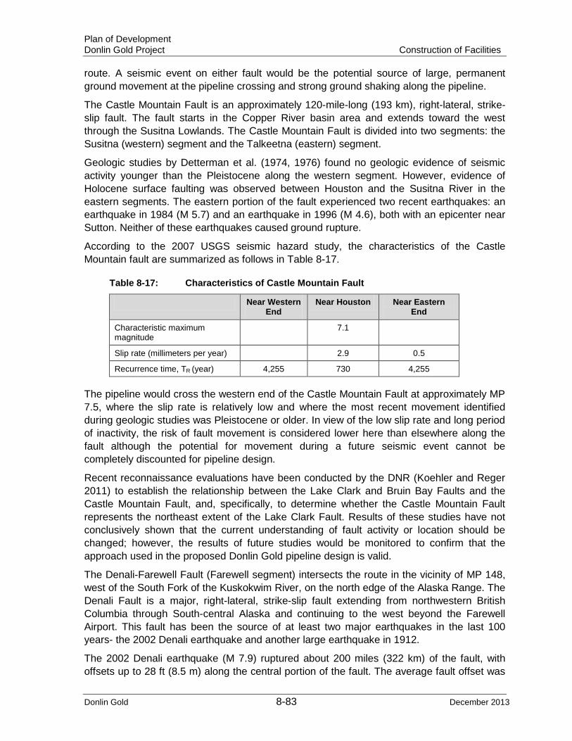
Plan of Development Donlin Gold Project Construction of Facilities
Donlin Gold 8-83 December 2013
route. A seismic event on either fault would be the potential source of large, permanent ground movement at the pipeline crossing and strong ground shaking along the pipeline.
The Castle Mountain Fault is an approximately 120-mile-long (193 km), right-lateral, strike-slip fault. The fault starts in the Copper River basin area and extends toward the west through the Susitna Lowlands. The Castle Mountain Fault is divided into two segments: the Susitna (western) segment and the Talkeetna (eastern) segment.
Geologic studies by Detterman et al. (1974, 1976) found no geologic evidence of seismic activity younger than the Pleistocene along the western segment. However, evidence of Holocene surface faulting was observed between Houston and the Susitna River in the eastern segments. The eastern portion of the fault experienced two recent earthquakes: an earthquake in 1984 (M 5.7) and an earthquake in 1996 (M 4.6), both with an epicenter near Sutton. Neither of these earthquakes caused ground rupture.
According to the 2007 USGS seismic hazard study, the characteristics of the Castle Mountain fault are summarized as follows in Table 8-17.
Table 8-17: Characteristics of Castle Mountain Fault
Near Western End
Near Houston Near Eastern End
Characteristic maximum magnitude
7.1
Slip rate (millimeters per year) 2.9 0.5
Recurrence time, TR (year) 4,255 730 4,255
The pipeline would cross the western end of the Castle Mountain Fault at approximately MP 7.5, where the slip rate is relatively low and where the most recent movement identified during geologic studies was Pleistocene or older. In view of the low slip rate and long period of inactivity, the risk of fault movement is considered lower here than elsewhere along the fault although the potential for movement during a future seismic event cannot be completely discounted for pipeline design.
Recent reconnaissance evaluations have been conducted by the DNR (Koehler and Reger 2011) to establish the relationship between the Lake Clark and Bruin Bay Faults and the Castle Mountain Fault, and, specifically, to determine whether the Castle Mountain Fault represents the northeast extent of the Lake Clark Fault. Results of these studies have not conclusively shown that the current understanding of fault activity or location should be changed; however, the results of future studies would be monitored to confirm that the approach used in the proposed Donlin Gold pipeline design is valid.
The Denali-Farewell Fault (Farewell segment) intersects the route in the vicinity of MP 148, west of the South Fork of the Kuskokwim River, on the north edge of the Alaska Range. The Denali Fault is a major, right-lateral, strike-slip fault extending from northwestern British Columbia through South-central Alaska and continuing to the west beyond the Farewell Airport. This fault has been the source of at least two major earthquakes in the last 100 years- the 2002 Denali earthquake and another large earthquake in 1912.
The 2002 Denali earthquake (M 7.9) ruptured about 200 miles (322 km) of the fault, with offsets up to 28 ft (8.5 m) along the central portion of the fault. The average fault offset was

Plan of Development Donlin Gold Project Construction of Facilities
Donlin Gold 8-84 December 2013
about 15 ft (4.6 m). The average vertical slip on the Denali Fault was measured to be about 15% of the horizontal and was predominantly north-side-up. After the 2002 Denali earthquake, the western end of the fault was extended to near the Farewell Airport.
An earthquake in 1912 (M 7.2 to 7.4) is believed to have ruptured the central portion of the Denali Fault. The epicenter of this earthquake is thought to have occurred approximately 25 miles (40 km) southwest of the Delta River Fault crossing (Plafker et al., 2004). Empirical data for this earthquake suggest that the surface rupture length was between 35 and 50 miles (56.3 to 80.5 km); the maximum horizontal movement is estimated to have ranged from 8 to 13 ft (2.4 to 4 m).
According to the 2007 USGS study (Wesson et al., 2007); the characteristics of the Denali Fault segments are summarized in the following Table 8-18.
Table 8-18: Characteristics of Denali Fault
Southeast Segment Central Segment Near Western
End Near Eastern End
Near Farewell
Near Cantwell
Near Junction to Totschundar Fault
Characteristic maximum magnitude
7.9
Slip rate (millimeters per year)
8.4 2
Recurrence time TR* (year)
1,065 4,465 15,305 1,630 1,065
SOURCE: USGS, 2007 *Recurrence time of Central Denali- Eastern Denali system
The pipeline route crosses the western end of the central Denali fault near Farewell, where the slip rate is lower. This lower slip rate suggests that the likelihood of future movement is lower than elsewhere along the fault. However, because the possibility of future movement cannot be ruled out, the pipeline design has addressed the potential for fault movement.
The estimate of potential permanent displacement was based on an earthquake of approximate magnitude 6. The preliminary recommended design displacement is 7 ft (2 m) of horizontal and 3 ft (0.9 m) of vertical movement for the Denali-Farewell Fault and 5 ft (1.5 m) of horizontal and 2 ft (0.6 m) of vertical movement for the Castle Mountain Fault.
The observed magnitude of the vertical offset along the western Castle Mountain fault is up to 13 ft (4 m) (Detterman et al., 1974) and that the lateral offset is up to 118 ft (36 m) (Willis et al., 2007). However, these offsets were the result from several earthquake events, not from a single event. According to the article by Willis et al. (2007), there were four earthquakes in the past 2,560 years. Therefore, the vertical offset per a single earthquake event is approximately 3 ft (0.9 m).
The design recommendations for the Castle Mountain Crossing were based on the most recent USGS seismic study for Alaska (2009), which is based on the study by Willis et al. (2007) for the Castle Mountain Fault. The study estimated a horizontal slip rate of 0.12 inches (3.2 mm) per year and indicated that a lateral offset of 4.3 to 8.5 ft (1.3 to 2.6 m) could occur for an earthquake if it occurs today. Assuming that the vertical offset is 20% of the horizontal displacement, as observed during the Denali earthquake although the geologic evidences across the Castle Mountain fault suggest approximately 10% of vertical

Plan of Development Donlin Gold Project Construction of Facilities
Donlin Gold 8-85 December 2013
to horizontal offset ratio, the estimated vertical offset is approximately 1.7 ft (0.5 m). A vertical offset of 2 ft (0.6 m) for the Castle Mountain fault crossing design was recommended.
It is understood the ADNR has conducted a field study on the Castle Mountain fault in 2011, and the results from the study would be published. The final design of the pipeline would include the latest available seismic information to support safe construction and operation.
The width over which the fault movement would occur is difficult to estimate. Based on review of LIDAR shaded relief mapping for the area and comparison to typical fault-crossing widths for strike slip faults, the zones of distortion for the Castle Mountain and Denali Faults were estimated to be 300 ft (91 m) and 1,000 ft (305 m) in width, respectively. A preliminary fault-crossing stress analysis conducted for both crossings produced a recommendation for an above grade design with the pipeline in a “Z” configuration at each end of the potential movement zone.
Final designs for the aboveground crossings at the Denali-Farewell and Castle Mountain Faults would be developed to allow the pipe to move freely on aboveground support beams during seismic shifting of the ground at these crossings resulting in acceptably low longitudinal stress for the pipe. Both are included as aboveground segments supported on grade beams and/or vertical support members (VSMs). The fault crossing design is based on the Trans-Alaska Pipeline System (TAPS) design for crossing the Denali Fault.
Both fault crossings would be located in areas used for sport/subsistence hunting, and therefore, would have some level of exposure to bullet strikes. The pipe WT at these locations would be increased, and the pipe would be protected with a steel plate shroud that would protect the top 270 degrees of the pipe circumference. This shroud would protect the pipe from accidental bullet strikes and would still allow the pipe to move on the horizontal supports to alleviate stress from seismic events at these locations.
8.6.19 Snow Avalanche Hazards Potential snow avalanche hazards would exist during winter and spring construction, where the pipeline alignment would be located near steep slopes in mountainous terrain in the Alaska Range. Most of the steep terrain occurs in sections which are scheduled for summer construction.
If snow avalanche hazard is identified, it may be mitigated by triggering the avalanche using explosive projectiles. During periods of extreme avalanche danger that cannot be safely controlled, work would be shut down until the danger is controlled or has passed. Monitoring would cease once the construction activity has moved beyond the hazard area and there is no further need to use the ROW. The pipeline would not be subject to further potential avalanche damage because it would be buried below the ground surface.
8.6.20 Unsuitable Soils There are few locations in the project area with slope stability issues. Locations with potential for slope instability are limited to the six mile interval over the Alaska Range divide from approximately MP 114.5 to MP 120.2. This section is characterized by steep mountain slopes and narrow valleys with relic protalus lobes, relic rock glaciers and talus slopes. Many of these features are permanently frozen and have potential for creep movement. Landslides and avalanches are characteristic occurrences in this terrain.
Plan of Development Donlin Gold Project Construction of Facilities
Donlin Gold 8-86 December 2013
The locations these unsuitable soil types have been found are as follows:
• Talus Slopes and Alluvial Fans- Numerous steep talus slopes exist along valley walls through the Alaska Range from approximately MP 114.5 to MP 120.2. Several active talus slopes are traversed at their toe and near the valley bottoms by the pipeline realignment from approximately MP 115-117 and MP 118-119.5.
• Avalanche- Avalanche zones occur at intervals along the alignment from approximately MP 114.5 to MP 120.2. Lower hazard areas exist from approximately MP 112.6 to MP 114.5 and MP 123.5 to MP 124.6.
This area of the alignment requires further field investigation and a detailed construction approach that would be addressed in final design.
8.6.21 Permafrost The pipeline route includes more than 100 miles (161 km) of discontinuous permafrost terrain, principally from MP 102 to MP 246. Construction must address the geotechnical conditions imposed by permafrost and the cold northern latitudes in the final engineering design.
Construction topics that would be influenced by the presence of permafrost include:
• Construction season selection • Lay direction • ROW mode selection and thickness of workpads • Frequency and location of material sites • Avoidance of sidehill cuts • Trenching methods • Use of padding for ice-rich soils • Mitigation of cuts in thaw-unstable permafrost • Access to the ROW in summer • Restoration
8.6.22 Mainline Block Valves and Launchers/Receivers All MLVs would be buried. An operator would extend aboveground and would be within a fenced area. The MLVs would be installed during construction of the mainline. They would be pigged, cleaned, filled, tested, dewatered (if and where water is used for testing), and dried as part of the mainline pressure testing.
Although to be confirmed during final design, valves NPS 4 and smaller would be equipped with lever-type operators. Valves NPS 4 and larger would be equipped with manual reduction gear operators. MLVs may be actuated at the BPL tie-in, compressor station, and at the pipeline terminus. All other MLV’s will be manually operated.
MLVs would be installed at a maximum spacing of 20 miles (32 km), depending on terrain and access during operations, and as required by 49 CFR 192. A closer spacing of MLVs may be required for areas of special environmental, geotechnical, or operational concerns. Review of spacing for these additional concerns such as fault lines would be done during final design.

Plan of Development Donlin Gold Project Construction of Facilities
Donlin Gold 8-87 December 2013
MLVs would be manually operated, below ground, full-port, through-conduit valves, in accordance with API 6D, with an ANSI 600 rating. Valve operators would be equipped with an extension to allow closure in conditions where significant snow cover may exist.
Two smaller, above grade blowdown valves would be installed upstream and downstream of each MLV.
• The blowdown valve would be approximately one-third the diameter of the MLV • Each blowdown valve would have a vertical stack topped by a blind flange or
removable cap to facilitate blowdown of the pipeline; if caps are provided, they would be manufactured to accept a padlock
Valve sites would be fenced with an 8-foot-high (2.4 m) chain link fence around the perimeter of a graded site. All MLV locations would require a pad approximately 25 x 25 ft (7.6 x 7.6 m) in area. Each site would be equipped with a helicopter pad for maintenance and emergency access. The compressor site and the metering station would both be road accessible.
Valves would be pressure-tested by the supplier in accordance with the valve specification issued with the procurement order. Valves would not be pressure-tested in line with the pipeline, unless dictated by access issues and season of installation. Valve assemblies would be pressure-tested as a whole.
All MLVs and pig launcher and receiver isolation valves would be full-opening, through-conduit, ball valves. Other types of valves such as plug valves may be used for utility lines on launchers and receivers.
Visual impacts would be reduced by using coated/colored aboveground valves, fencing and gates. See Section 6.10 for additional information.
8.6.23 Cathodic Protection In addition to the pipe coating, a current-passive, zinc ribbon Cathodic Protection (CP) system would be used for the length of the pipeline.
Zinc ribbon would be installed after pipe lowering-in and before backfill. CP stations for continuity checks would be installed at approximate 1-mile (1.6 km) intervals.
Test stations would be installed where the pipeline parallels, crosses, or passes near other cathodically protected pipelines or structures. The pipeline would be electrically isolated from contact with the BPL. See Sections 6.12 and 11.11.
8.6.24 Cleanup, Erosion Control and Reclamation Crews The final cleanup, erosion control, and reclamation work would be done by two different
crews. The cleanup crew would follow behind the backfill crew and perform all cleanup, reclamation of cuts when possible, and planned temporary and permanent erosion control to help provide long-term stability and to prevent excessive soil erosion as well as divert water to stable areas adjacent to the pipeline, during the same season as pipe installation.
The reclamation crew would go back over the ROW during the summer after a winter season to fix any erosion control problems that have developed during breakup, and reclamation problems with the trench line and working side, and assess and address any permafrost degradation that is evident. In a summer section, the reclamation crew would
Plan of Development Donlin Gold Project Construction of Facilities
Donlin Gold 8-88 December 2013
follow the cleanup crew during the same summer. This double coverage of erosion control and reclamation efforts in permafrost terrain would provide additional protection of these sensitive areas.
The cleanup and reclamation crews would be different, depending on the type of ROW being constructed.
For ice pad or frost-packed ROW mode (winter only):
• Cleanup ice pad crew (would work during the same winter season as pipe lay)
− Would be primarily concerned with the trench line and mounding material over the trench
− Would install erosion control for ice-rich trench spoil − Would restore cross-drainages
• Reclaim ice pad crew (would work during the summer immediately after the winter)
− Initial focus in early summer would be on problem areas that developed during breakup
− Would travel ROW and repair problems − Would prevent significant erosion from developing along the ice-rich trench
For gravel workpad (winter or summer):
• Cleanup workpad crew (would work during the same season as pipe lay)
− Would clean up trench line and spoil area − Would not remove workpadit would be left in place − Would install erosion control on trench line and workpad − Would establish permanent cross-drainages across workpad
• Reclaim workpad crew (would work during the summer after the winter or the same summer)
− Would require LGP equipment to deal with trench line and spoil side − Would complete any workpad reclamation work
For graded ROW (winter or summer):
• Cleanup graded ROW crew (would work during the same season as pipe lay)
− Would restore cuts and contours as appropriate − Would work entire ROW width including extra workspace for cuts and fills − Would install erosion control across full width of ROW
• Reclaim graded ROW crew (would work during the summer after the winter or during the same summer)
− Would complete ROW reclamation work
In most sections, several different ROW construction modes would be used. In some winter sections, there would be an ice pad, a gravel workpad, and some graded ROW. For sections with mixed ROW modes, the plan includes different cleanup crews and reclamation crews that match all ROW modes. Cleanup and reclamation crews in each section would be configured for all ROW modes to be used in that section.
Plan of Development Donlin Gold Project Construction of Facilities
Donlin Gold 8-89 December 2013
Drainage and erosion control measures, both temporary and permanent, would need to be implemented along the pipeline ROW and at facilities such as camps, storage yards, material sites, and airstrips.
Cleanup and stabilization, rehabilitation and reclamation of the surface along the ROW and any temporary use areas would be performed by removing and disposing of construction debris and performing final grading of remaining gravel pads to appropriate contours to allow proper drainage. Steps would be taken to minimize erosion, establish appropriate ground contours where necessary, and account for trench settling. These activities would be performed in accordance with permit stipulations and the Stabilization, Rehabilitation and Reclamation Plan. Sections 10.2, 10.3 and 10.4 contain detailed information regarding crew responsibilities. Donlin Gold recognizes that monitoring of reclamation actions would be consistent with the approved Stabilization, Rehabilitation Plan and the Pipeline Surveillance and Monitoring Plan.
8.6.25 Cleaning, Pressure Testing and Drying Before being tested, the pipeline would be cleaned of construction debris using a cleaning
pig(s). At the ends of each test section of the pipeline, temporary low-pressure launching and receiving barrels would be installed to facilitate launching and receiving the cleaning pig run. The cleaning pig would be pushed through the test section with compressed air. Once the test section has been determined to be free of debris, the temporary cleaning headers would be removed. The cleaning pig run may be done at the end of the winter construction season before breakup. This would remove obstructions in the line that may otherwise prevent successful fill pig runs in summer.
After the cleaning pig run(s), a caliper pig would also be run. If any dents or ovalities are found in winter, the pipe can still be excavated on the winter ROW, cut, the dent or ovality replaced with new pipe, and the pipe re-welded.
Pressure Testing The entire pipeline would be tested in compliance with USDOT regulations (49 CFR 192). Before the pressure test, each section of pipe would be cleaned.
The pipeline would be pressure tested before it is put into service to verify its integrity and its ability to withstand maximum operating pressures. All water testing would most likely be done in the summer to avoid the need to deal with water at below-freezing air temperatures. Donlin Gold has not yet determined whether the pipeline would be pressure tested using water or air or a combination. A detailed Pressure Test Plan would be developed during final design.
In testing, incremental segments of pipe would be filled with air or water, pressurized, and held for the required duration of the test. The length of each segment tested would depend on topography. Specifically for hydrotest sections, the head pressure from the water column in areas of significant elevation change can over pressurize the pipe if the hydrotest section has not been carefully engineered to account for this pressure. This is less of an issue for air pressure testing.
The selection of air or hydrotesting would depend on the time of year when the test is conducted, (winter hydrotesting is difficult because of freezing of water in pipe) the availability of hydrotest water for that pipe segment, and the experience level of the pipeline

Plan of Development Donlin Gold Project Construction of Facilities
Donlin Gold 8-90 December 2013
contractor with each test method. To conduct hydrotesting, tests of individual segments typically would be conducted in a sequence in which the test water would be transferred from one segment to another. Test water would be obtained from approved sources in accordance with permit requirements; screens on the intake hoses at surface water sources would be used to prevent entrainment of fish or other aquatic species and to monitor the withdrawal rate to maintain adequate downstream flow to support aquatic life. Volumes of water required would vary, depending on hydrotest segment length but could be up to 15 million gallons. Air testing could be conducted at any time of the year because freezing temperatures would not affect the pipe or test equipment for this operation.
The average length of an air test section would be approximately 50 miles (80 km). Air test requirements and durations are established by 49 CFR Part 192. Relatively large equipment is required to conduct the air test; therefore, adequate lifting equipment must be available to handle the compressors and after coolers during mobilization and demobilization of each air test site. Timing information regarding testing would be available to the public through Donlin Gold’s Public Outreach. Test and timing details would be included in the Pressure Test Plan to be developed during final design. Since timing for the majority of testing would be during the summer and movement of personnel and equipment would most likely be by air there would be intermittent noise as testing occurs.
Discharge of Hydro-testing Waters Once hydrostatic testing has been completed, test water would be discharged back to an approved location through a filtration device. Water used for pipeline test purposes would be tested before discharge, as required by project permits. Energy-dissipating devices and/or filter bags would be used to prevent scour, erosion, suspension of sediment, and damage to vegetation. Discharge rates would be monitored and kept within a range appropriate to maintain the effectiveness of the energy-dissipating devices.
Drying Once all the water has been pigged from the test section, the test heads would be cut off
and several test sections would be tied in to form a longer section that is more efficient for gauging and drying.
After dewatering, multiple runs of foam swab pigs would be made by the contractor using compressors and a dehydrator. The swab pigs would be run until they come out dry. The dehydrator would continue running until the air being discharged at the other end of the line meets the dryness requirements in the specifications.
8.7 Pipeline Commissioning After pressure testing, any necessary tie-ins would be made. The welds on the tie-ins would be inspected and the pipeline dried (if required) before commissioning begins. Commissioning would include testing of controls and communication systems before pipeline operation. The schedule would allow for gas delivery date to the Donlin Gold mine site in approximately no earlier than July 2019 depending upon when authorizations for the project are received and construction commences.

Plan of Development Donlin Gold Project Construction of Facilities
Donlin Gold 8-91 December 2013
8.8 Engineering Drawings and Specifications Preliminary engineering has been completed for the pipeline and the associated facilities. Appendices E and G, respectively, contain typical engineering design drawings of appurtenances and crossing types, and construction modes.
8.9 Waste Management
A Comprehensive Waste Management Plan would be developed and followed so that wastes generated by construction activities are minimized, identified, handled, stored, transported, and disposed of in a safe and environmentally responsible manner and in full compliance with applicable state, federal, and local laws and regulations. By policy, BLM does not consider establishing landfill(s) (“permitted disposal pits") on BLM managed or administered land.
Construction wastes would be managed by the construction contractors. Waste including food-type wastes generated by construction camps may be incinerated or shipped off-site. Large-scale wood products would be burned in accordance with permit stipulations as may be authorized by ADEC and the land manager.
All non-combustible solid waste would be shipped to off-site locations for proper disposal or recycling. Used oil would either be consumed by oil burners for energy recovery or shipped out to authorized recycling facilities.
8.10 Safety and Training Requirements
8.10.1 Environmental, Safety and Project Orientation/Training Before working in the field, all personnel would receive HSE training. The training program would focus on applicable state or federal regulations as well as project-specific permit conditions and mitigation plans. The training would include cultural sensitivity training. A project orientation would be conducted that would focus on camp rules, prohibited items (for example, pets, drugs, alcohol, and firearms), mobilization, equipment operations safety, waste management, medical and emergency response, fire prevention, invasive species and related topics. Safety training would be a major component of the orientation. A safety plan is an element of a comprehensive HSE management system. A detailed set of HSE plans would be developed before mobilization. The plan would take into consideration applicable health and safety regulations including the items listed below:
• Audits and inspections • Behavior-based safety • Blasting and use of explosives • Bloodborne pathogens • Climate: heat stress and hypothermia • Confined space entry • Cranes and derricks • Drilling • Electrical • Emergency action plans

Plan of Development Donlin Gold Project Construction of Facilities
Donlin Gold 8-92 December 2013
• Excavations • Fall protection • Fire protection and prevention • Firearms safety • Fitness for duty • Gases, vapors, fumes, dusts, and mists • Hazard communications • Heavy equipment safety • Helicopter safety • HSE training before mobilization • Illumination • Incident investigation • Injury management and return to work • Invasive species • Ladders • Materials handling, storage and disposal • Medical services, evacuation, and extraction • Occupational noise exposure • Personal protective equipment • Power transmission and distribution • Rigging • Sanitation • Scaffolds and elevated work platforms • Signs, signals, and barricades • Task hazard analysis • Tools: hand and power • Toxic and hazardous substances • Traffic control • Ventilation • Water safety • Welding and cutting • Wildlife safety
The bulk of the health and safety requirements for the pipeline construction would fall under 29 CFR 1926, Health and Safety for Construction. The OSHA General Duty Clause, Recordkeeping, and some general industry standards as well as 29 CFR 1910 also apply. In addition, the State of Alaska has a state-run occupational safety and health program that would apply. The requirements of 8 AAC 61-62.00070 would also apply as health and safety regulations during construction. A successful construction project implements several industry best practices beyond the applicable regulations; these practices would be incorporated into a project HSE plan.
Plan of Development Donlin Gold Project Construction of Facilities
Donlin Gold 8-93 December 2013
Best practices included in HSE plans and programs include behavior-based safety, soft tissue injury prevention programs, task hazard analysis, tools, survival training, and fitness for duty programs, for example.
8.11 Environmental and Quality Control and Procedures for Inspection Inspections would be conducted during construction, operation, maintenance, and termination to ensure compliance with regulatory, operational, maintenance and termination requirements, procedures and best management practices. The Pipeline Integrity Management System (or equivalent) and approved contractor Quality Assurance and Control Plans and O&M Plan/Manual provide for this. In addition, a system would be developed and implemented to react quickly and efficiently to any deviations to identified standards. Appropriately trained and qualified inspectors would monitor construction activities. A set of complete records would be kept for reference during pipeline operation and maintenance and for future projects involving the pipeline.
Inspectors would be responsible for verifying that the work is done according to established procedures, specifications, and drawings. The inspectors are in the field and inspect specific crews and work. They also document the physical progress of construction crews. The inspectors work for the owner or the construction management contractor and report directly to the chief inspector or designated assistant. The construction plan includes provisions for the third-party quality control inspectors. Some activities such as welding may require more than one inspector. More inspectors would be present during summer work to inspect civil activities unique to summer construction such as bedding/padding production and workpad construction.
The inspectors included are the engineering and construction management (ECM) contractor’s inspectors, not the pipeline contractor’s inspectors. The pipeline contractor would not provide quality control inspectors. On large projects, contractors usually employ environmental, safety, and welding/AUT engineers on their staffs to interface with crews and client/owner/regulatory personnel about those important activities.
Environmental inspectors are included for each construction spread to monitor environmental compliance. The environmental inspectors would be responsible for monitoring compliance with mitigation requirements of permits, regulations, certificates, and other approvals of an environmental nature that are issued for the project. The construction contractor's implementation of environmental mitigation measures would be inspected. The environmental inspectors would have the authority to stop activities that violate environmental conditions and to order corrective actions to maintain environmental compliance.
All inspections and compliance with construction and environmental requirements would be documented as well as any required remedial action that is taken. These documented actions would be reported to appropriate Donlin Gold managers and applicable regulatory agencies and landowners consistent with regulatory requirements.
There would be a smaller crew that conducts pressure testing, final tie-ins, and/or preliminary civil work. This smaller crew would also be used for preliminary ROW preparation in November and December.

Plan of Development Donlin Gold Project Construction of Facilities
Donlin Gold 8-94 December 2013
Donlin Gold procedures would be established to specify appropriate inspection reporting protocols to be followed by Donlin Gold personnel as well as contract personnel.
Agency personnel, both state and federal are expected to perform regulatory monitoring, inspection and compliance actions of the pipeline project throughout the life of the project as may be required by their respective agencies.
8.12 Signs and Markers Pipeline line markers and aerial milepost markers and warning signs at any roads, trails, streams, rivers, etc., would be installed as soon as practical and as required during construction in compliance with 49 CFR 192. The markers and signs would be constructed and installed to withstand vandalism to the extent feasible. Because the pipeline would cross state, federal, CIRI and Calista lands as well as being located in part within the Matanuska-Susitna borough additional signage may be required besides that of the pipeline regulatory agencies. Donlin Gold would coordinate the development of signage requirements with the appropriate entities to address concerns if signage became an issue. Review sections 3.11.2, 6.11 and 11.5 for additional information.
8.13 As-Built Survey There would be an as-built survey of the pipe after it has been lowered into the trench but before padding or backfilling. The as-built survey would record the location of every weld and bend, and the elevation and horizontal location of the pipe, as well as record locations of cathodic protection installations, valves, launchers and receivers, and all other appurtenances.
8.14 Contingency Planning Contractors would be required to prepare contingency plans for construction. Each plan would address specific contingencies related to particular aspects of the project. Plans would be developed in accordance with all pertinent regulations and would follow BMPs. Any necessary field changes to plans would be identified, documented, and approved by the appropriate agencies before implementation, and necessary records maintained.
8.15 Contacts
8.15.1 Holder Contacts DONLIN GOLD LLC 4720 Business Park Blvd., Suite G-25 Anchorage, Alaska 99503 Attention: Robert Enos Environmental and Permitting Manager (907) 279-0383 Email: [email protected]
Plan of Development Donlin Gold Project Construction of Facilities
Donlin Gold 8-95 December 2013
8.15.2 ROW Granting Contacts Bureau of Land Management
Alan Bittner, Field Manager Anchorage Field Office 4700 BLM Road Anchorage, Alaska 99507 (907) 267-1285 Facsimile: (907) 267-1268 Email: [email protected]
State Pipeline Coordinator’s Office State of Alaska Pipeline Coordinator’s Office 411 W. 4th Avenue, Suite 2 Anchorage, Alaska 99501-2343 Facsimile: (907) 272-0690 Email: [email protected]
Private Landowner Contacts Calista Corporation Ms. June McAtee, Vice President of Land and Natural Resources 301 Calista Court, Suite A Anchorage, AK 99518 (907) 279-5516
Cook Inlet Region Corporation Ms. Dara Glass, Land Manager 2525 C Street, Suite 500 Anchorage, AK 99503 (907) 263-5140

Plan of Development Donlin Gold Project Resource Values & Environmental Concerns
Donlin Gold 9-1 December 2013
9.0 Resource Values and Environmental Concerns Resource values and environmental concerns for the pipeline route are summarized in this section. Impacts to resources during the construction phase of the pipeline project are expected to be temporary and localized and associated primarily with the construction related activities. As a result of the creation of the pipeline corridor there may be alteration to use patterns and access, and effects on wildlife and fish resources could extend beyond the construction period.
9.1 Location with Respect to Existing Corridors The pipeline route traverses a remote area with very little development and little or no supporting infrastructure. There is no utility corridor along the route. The route follows, parallels, and crosses the INHT and the State’s Public Access Easement for the Iditarod Race Trail as discussed in Section 8.1.1. The ADL 222930/RST-199 is the main transportation route in this region. Review Sections 3.11.2, 8.1.1, 8.6.17 and 10.8 and Appendix A and B for additional information.
Donlin Gold would continue to make information available and meet with local residents and the public regarding the proposed project so that they are able to provide input and express interest or concerns regarding the project.
9.2 Anticipated Conflicts with Resources or Public Health and Safety
9.2.1 Air Construction and operation of the pipeline is not expected to have significant impacts on air quality within the project area. The pipeline would be located in remote areas far from existing major sources of air pollutants. There are relatively few sources of potential air pollution in the immediate vicinity of the pipeline, and the air quality in this remote area meets all Alaska and federal standards for criteria pollutants. The pipeline project area in its entirety is designated as a federal Class II airshed under the federal Clean Air Act. The nearest Class I airshed is the Denali National Park and Preserve. No stationary source of emissions would be located within 4.4 miles (7 km) of the boundary of the Park and Preserve which is the closest distance that the pipeline would be to the Park and Preserve boundary. Another Class I area is located near the Beluga Gas Field, the Tuxedni Wilderness Area. The Tuxedni Wilderness Area is located approximately 93 miles (150 km) from the nearest point of the pipeline.
The pipeline compressor station and a portion of the proposed pipeline would be located within the Cook Inlet Intrastate Air Quality Control Region. This region encompasses the entire Cook Inlet Basin, with the exception of the Municipality of Anchorage. There are currently no permitted sources of air pollution in the region within 3.2 miles (5.2 km) of the pipeline or compressor station.
The compressor station would be powered by electricity provided by existing infrastructure, and no diesel or natural gas-fired backup generators are planned. Therefore, no significant emissions are expected to be generated.

Plan of Development Donlin Gold Project Resource Values & Environmental Concerns
Donlin Gold 9-2 December 2013
Construction Phase The project would have a localized effect on air quality during the construction phase, primarily because of the use of diesel-powered mobile construction equipment and the generation of some windblown dust during construction seasons with no snow, or during summer construction. BMPs would be employed to reduce the potential for windblown dust emissions. Fugitive dust emissions would be managed as a safety issue when necessary for construction personnel traveling on the ROW as well as to reduce impacts to the environment surrounding the pipeline corridor. Some open burning may be required during construction to dispose of burnable items such as packaging wastes and pallets. Any open burning would be conducted in accordance with authorizing permit requirements. No open burning of slash generated by ROW-clearing activities would be conducted.
Estimates for emissions from camps and construction equipment would be developed during final design.
Construction activities would require the implementation of measures for minimizing short-term impacts on air quality. These include:
• Developing and implementing a quality control/quality assurance program as well as a Permits and Environmental Compliance Program that would track and confirm implementation of all permit conditions associated with eliminating or reducing impacts on local air quality.
• Use of appropriate BMPs to reduce fugitive dust from construction traffic such as limiting traffic and disturbance of soils where possible, stabilizing and maintaining stability of disturbed soil, or spraying water, spreading snow or applying another approved dust suppressant depending on season and conditions.
• Burning or incinerating waste at times that minimize impacts to air quality. • Using construction camp incinerators to dispose of only those materials that the
incinerator is designed and permitted to burn. Incinerators would be used in accordance with the BMPs for these incinerators and according to the standard operating procedures to minimize emissions during incineration.
Operation Phase Compressor station equipment would be electrically powered, and no stationary internal combustion engines would be used during system operation. As a result, compressor station emissions are expected to be negligible.
The proposed project-maintenance-related activity along the pipeline would be primarily vehicle and helicopter traffic, resulting in a smaller, localized, insignificant effect on air quality. In the rare case in which a pipeline segment may have to be depressurized and gas removed from the pipe for maintenance, release of natural gas to the atmosphere will occur.
Potential Effects The potential effects on air quality could include:
• Short term fugitive dust from construction activities - trucks bringing materials, heavy equipment trenching and moving pipe, construction and personnel transport vehicles, aircraft landing and taking off, burning or incinerating permitted wastes and blasting should it occur.
• Release of natural gas during some maintenance activities.

Plan of Development Donlin Gold Project Resource Values & Environmental Concerns
Donlin Gold 9-3 December 2013
• Minor increases in PM, NOx, SO2 and VOC emissions from construction equipment and non-natural gas fuel burning equipment.
Mitigation Mitigation measures that can be implemented to address effects on air quality include:
• Preparation and implementation of a Dust Control Plan using best practical methods (BPMs) during construction activities to minimize fugitive dust emissions.
• Development and implementation of BMPs for construction activities to reduce emissions.
9.2.2 Noise With the exception of the southern terminus and a few isolated locations along the pipeline route (Rainy Pass Lodge, the confluence of the Talachulitna and Skwentna Rivers, scattered cabins, and primitive airstrips), there are no fixed sources of anthropogenic noise along the corridor. Transient noise from aircraft overflights and the operation of snowmachines or off-highway vehicles do occur.
Ambient noise levels increase temporarily along the portions of the pipeline route traversed by the Iron Dog Race Route because of increased snowmachine use during the event, which lasts for several days in early March. The same is true for the Iditarod sled dog race when it normally occurs in March. Light aircraft noise also increases in portions of the route in the vicinity of the Iditarod Trail before the race as supplies are delivered to the various check points and during the race as personnel and dogs are transported to and from the race route.
Construction Phase Increased noise levels during project construction activities would be localized and transitory as construction activity proceeds at various locations along the length of the approximately 315-mile (507 km) pipeline. The primary sources of construction-related noise would include helicopter traffic, diesel-powered mobile equipment, pipe installation equipment, equipment operating at material sites and construction worker verbal communication or in the event that blasting would be necessary. Construction of approximately 67% of the pipeline length is anticipated to occur during the winter.
Operation Phase The proposed project should have little to no effect on existing noise during project operation. The project compressor station would use electrically powered equipment that would be located within structures that are designed to abate noise. The fin-fan cooling units would be located outside compressor modules and would generate small levels of noise not expected to carry significantly past compressor station fence limits. Some additional, short-term noise increase would result from all-terrain vehicle (ATV)/snowmachine/vehicle traffic and small, fixed-wing aircraft and helicopters during pipeline maintenance and/or surveillance, inspection and monitoring activities.
Potential Effects
Increased noise from equipment during construction, aircraft flights, and maintenance during the life of the pipeline could affect subsistence, recreational, and resident users along the corridor, more specifically:
Plan of Development Donlin Gold Project Resource Values & Environmental Concerns
Donlin Gold 9-4 December 2013
• Short term increases in ambient noise levels from construction activities, trucks bringing materials, heavy equipment trenching and moving pipe, human interactions (radios, conversations, and construction and personnel transport vehicles) and blasting.
• Fixed-wing aircraft and helicopter traffic would be most prevalent during construction and reduced to surveillance, inspection and monitoring as well as maintenance activities once construction is completed.
• The effects of construction noise on commercial lodge operations that occur in the vicinity of the pipeline would be limited to the short duration of the construction period which would occur primarily during the winter months. Animals may be displaced which may affect guiding operations and other hunting activities near the ROW.
• The effects of operation and maintenance noise on commercial guide/lodge operations that occur in the vicinity of the pipeline would be limited to possible monitoring and inspection activities and any maintenance necessary to maintain the operational integrity of the pipeline including periodic clearing of shrubs from the ROW.
• The effects of noise resulting from termination of pipeline activities on commercial guide/lodge operations that occur in the vicinity of the pipeline would be minimal as it is anticipated that the pipeline would be abandoned in place except for aboveground portions and facilities.
• The effects of construction noise on wildlife would be short term as construction progresses at various locations along the ROW and causes temporary displacement of some wildlife from the adjacent area of activity. Animals that are displaced may affect guiding operations and other hunting activities near the ROW. Noise should have little direct effect on people because of the remoteness of the location and small numbers of people living in or transitioning through close proximity to the construction. However, temporary displacement of some wildlife may also affect subsistence hunting and subsistence lifestyle.
Mitigation Mitigation measures that will be implemented to address the effects of noise include:
• Development and implementation of a Construction Communications Plan to inform the public and commercial operators of construction activities
• When possible implement a flight avoidance policy in specific areas where commercial lodges are located
• Whenever possible implement a policy to avoid generating loud noise levels that may impact local residents and /or wildlife
9.2.3 Geologic Hazards The benefit of undertaking a geologic hazard assessment of the pipeline route is to provide information to specify effective design, construction, and operational mitigation measures to address pipe integrity issues from these geologic hazards. Known geologic hazards were taken into account in this proposed pipeline routing and pipeline facility design. A geologic hazard is defined as a naturally occurring or project-induced geological, geotechnical, or hydrological phenomenon that could load or displace the pipeline, causing a pipeline integrity concern, or that could impact the ROW, causing an environmental concern.

Plan of Development Donlin Gold Project Resource Values & Environmental Concerns
Donlin Gold 9-5 December 2013
Potential Effects Seismicity, faulting, and ground shaking represent potential geologic hazards to the pipeline, either from the direct effects of ground shaking or from the consequences of permanent ground displacement. Seismically induced ground shaking can also result in a number of collateral geologic hazards such as liquefaction, seismically induced settlement and slope instability, and pipe flotation.
A number of other geologic hazards exist along an arctic or subarctic pipeline route that are addressed in the proposed Donlin Gold pipeline design. The main non-seismic geotechnical hazards that can have a detrimental effect on pipeline integrity include:
• Slope instability • Frost heave • Thaw settlement • Snow avalanche • Potential icing (aufeis) • Riverbank erosion • River channel scour • Landslides • Hydrotechnics/watercourse hydraulics • Erosion
Mitigation Mitigation measures that will be implemented during construction and operations and maintenance to address effects of geologic hazards on the integrity of the proposed pipeline project include:
• Design Considerations - Pipeline routing - Special installation techniques and foundations - Earthquake mitigation and special design considerations at fault crossings - Special design considerations at river crossings - Erosion control measures
• Operational Considerations - Slope stability monitoring - Seismic/earthquake monitoring - River hydrology monitoring - O&M Plan/Manual - Other controls to be determined.
9.2.4 Mineral and Energy Resources The proposed pipeline route crosses the Kiska Metals Corporation mineral exploration claims in the area where the pipeline is being routed around the west side of Round Mountain. The project is assessing potential gold, silver, and copper resources and is currently in the exploratory phase. The primary area of interest is away from the pipeline route and there is limited potential for possible conflicts between development of any resource, should it occur, and the alignment.

Plan of Development Donlin Gold Project Resource Values & Environmental Concerns
Donlin Gold 9-6 December 2013
Potential Effects The potential effects may include: • Potential increased access opportunities
Mitigation Mitigation measures that can be implemented to address effects on mineral and other resource development activities include:
• Coordination with existing or potential mineral and oil and gas developers in the area to address potential requests to utilize airstrips, barge landings or the ROW.
• Work with land-owners to address access concerns
9.2.5 Paleontological Resources
Paleontological resources are fossilized remains, imprints, and trace fossils of plants and animals used to study past ecosystems, evolution, and the origination and destruction of organisms. Ground-disturbing activities have the potential to adversely affect paleontological resources, particularly if those activities extend below alluvial deposits or deep soils and into sedimentary rock. There are paleontological resources including graptolites in the vicinity of the pipeline route. However the pipeline would be buried in alluvia/fluvial material in these areas and not affect bedrock.
Fossils are protected by the Antiquities Act of 1906, as they are non-renewable resources. In addition, fossils on federal lands are protected by the Federal Land Policy and Management Act of 1976 (FLPMA). The Paleontological Resources Preservation Act (PRPA) was passed into law on March 30, 2009. The PRPA requires the management and protection of paleontological resources on federal land by the Secretaries of the Interior and Agriculture (U.S. Code: 16 USC 470). Specific provisions for the various land-managing agencies reinforce policies regarding the collection and curation of paleontological resources and the confidentiality of location information. Fossils associated with archaeological sites and large caves are protected by the Archaeological Resources Protection Act (ARPA) of 1979 and the Federal Cave Resources Act of 1988. The Alaska Historic Preservation Act (AHPA) protects paleontological resources in Alaska.
Potential Effects The potential effects on paleontological resources could be:
• Ground disturbing construction activities such as trenching, grading, or excavation may turn-up resources previously not identified.
• Development of work areas, travel lanes, pipeline storage yards, camps, fuel storage sites, material storage areas, disposal sites, materials sites, access roads and the placement of fill over the resources could unknowingly occur.
Mitigation Avoidance is the preferred mitigation measure. If permanent effects are unavoidable, they should be mitigated in accordance with the requirements of the appropriate agencies and applicable laws.
If any known or previously undiscovered significant paleontological resources are encountered during construction activities, the contractor or Donlin Gold would contact the

Plan of Development Donlin Gold Project Resource Values & Environmental Concerns
Donlin Gold 9-7 December 2013
SPCO (if on state lands) and the appropriate federal authority responsible for paleontological and cultural resources if on public land.
There is always the possibility that paleontological resources would be discovered during the project. Measures for protection of known and unanticipated discoveries of paleontological and cultural resources and sites would be addressed in the Donlin Gold Paleontological and Cultural Resources Protection Plan.
9.2.6 Cultural Resources The proposed pipeline route crosses lands managed by the State of Alaska, the BLM, Calista, and CIRI. Because the project would require state and federal permits and other agency approvals, it represents a federal undertaking and must comply with Section 106 of the NHPA. To comply with this requirement, a Phase I identification survey of the pipeline corridor was conducted in the summers of 2010, 2011 and 2012. Field and archival data on historic resources necessary to complete Phase II evaluations were also collected with particular attention paid to the INHT and any associated sites.
The cultural resources study area was defined as a 300-foot-wide (91 m) corridor. The Area of Potential Effect (APE) for cultural resources will be determined as part of the Section 106 process in consultation with the SHPO, Army Corps of Engineers, affected tribes, and cooperating agencies. For the proposed mainline pipeline route a Phase I survey using SHPO standards was conducted to identify cultural resources within the 300 ft (91 m) construction planning corridor. The survey included helicopter-based surveys and pedestrian transect surveys.
For the pipeline route identified in the July 2012 PoD, a total of 37 cultural resources were identified during project background research and field survey. Research found 26 newly discovered sites and 11 were previously known. Of the 37 resources identified, 22 were located within the study area.
The boundaries of some of the cultural resources that were identified require further delineation and additional site testing to evaluate their eligibility for the National Register of Historic Places. This work would be completed in subsequent seasons for those located within the realigned proposed pipeline route which now includes the Jones Alternate replacing the portion of the previous alignment referred to as the Rainy Pass Alternate. Additionally the Pretty Creek Alternate now replaces the East Theodore Alternate. Phase I and II surveys of the Jones Alternate were carried out during the 2013 field season. Nine new prehistoric sites and one recent use site were identified along this portion of the route. The Pretty Creek Alternate was also surveyed and one prehistoric site was identified.

Plan of Development Donlin Gold Project Resource Values & Environmental Concerns
Donlin Gold 9-8 December 2013
Potential Effects Potential effects on cultural resources could include:
• Ground-disturbing construction activities such as trenching and grading could reveal new cultural resources.
• Development of workpads, pipeline storage sites, camps, fuel storage sites, materials storage sites, material sites airstrips, etc. could reveal previously unidentified cultural resources.
Mitigation Donlin Gold would use the following protective measures during the planning and construction of the pipeline:
• Identifying cultural resources, in accordance with the NHPA and contact appropriate agency personnel if new resources are found.
• Avoiding, to the maximum extent practicable, significant cultural resources. • Participating in consultation in accordance with AS 41.35 and Section 106 of the
NHPA to determine the potential for adverse impacts on identified cultural resources.
• Mitigating adverse effects in accordance with Section 106 of the NHPA and in accordance with the Programmatic Agreement for cultural resources, developed in coordination with the SHPO, USACE, affected tribes, and cooperating agencies.
Inventory, documentation, and preservation of cultural resources and traditional cultural properties and mitigation of adverse impacts would be based on a programmatic agreement among the concerned federal permitting entities, the SHPO, and the federal Advisory Council on Historic Preservation. The agreement initiated by the agencies would clarify procedures for considering cultural resources and would formalize the relationships among the various agencies. The relevant, federally recognized Tribes and other members of the public could participate in the implementation of the agreement, as required by NHPA Section 106. Measures for protection of known and unanticipated discoveries of paleontological and cultural resources and sites would be addressed in the Donlin Gold Paleontological and Cultural Resources Protection Plan.
Donlin Gold would require all employees and contractors to protect cultural resources. Should any sites or suspected sites be discovered during construction, operations, maintenance, and termination activities, the activities that may disturb or damage the site would cease and the appropriate procedures stipulated in the Programmatic Agreement would be followed.
9.2.7 Regional Setting Climate The climate in the vicinity of the southern portion of the pipeline (Beluga to Skwentna) is mild by Alaska standards because of seacoast proximity. Daytime temperatures in summer average between 55oF and 75oF (13oC and 24oC) with occasionally hotter days. Winter temperatures can drop as low as -40oF (-40oC) but typically range from -15o to 30oF (-18o to -1oC). On average, this area receives 16 inches (406 mm) of precipitation per year, with approximately 75 inches (1,905 mm) of snow, although there are areas in the south central portion of the area that receive far more snow. The climate of the project area is classified as subarctic because of its brief, cool summers.

Plan of Development Donlin Gold Project Resource Values & Environmental Concerns
Donlin Gold 9-9 December 2013
The climate of the western portion of the pipeline route (from Skwentna to the Donlin Gold mine site) is determined, in large part, by weather from the Bering Sea and cold fronts from the arctic. This climate is a subarctic oceanic climate in the southwestern portion of the area and a continental subarctic climate farther inland. The temperature is somewhat moderate and there is a significant variability in precipitation. The northern side of the Seward Peninsula is technically a desert, with less than 10 inches (254 mm) of precipitation annually; some locations between Dillingham and Bethel average approximately 100 inches (2,540 mm) of precipitation. Daytime temperatures in the Southwest Interior during the summer range from 50o to 80oF (10o to 27oC); winter temperatures are typically cold, ranging from -40o to 10o F (-40o to -12o C).
Physiographic Divisions The approximately 315-mile-long (507 km) pipeline route crosses five major physiographic divisions between its start near Beluga and its terminus at the Donlin Gold mine site as shown in Figure 9-1.
• Cook Inlet/Susitna Lowland Region: The route initially traverses the Cook Inlet/Susitna Lowland Region, the eastern flanks of Little Mount Susitna and Beluga Mountain, and the lower reaches of the Skwentna River valley, to approximately MP 77.
• Alaska Range Region: From Cook Inlet/Susitna Lowland Region, the route enters the Alaska Range physiographic region, continuing northwesterly up the Skwentna Valley. The Jones Alternate deviates from the previously proposed Rainy Pass Alternate at approximately MP 106. From this point the pipeline trends northwest to a crossing of the Happy River and proceeds to the broad Threemile Creek Valley. At approximately MP 114.5 the alignment trends westerly as it approaches an unnamed pass that is the Alaska Range divide. This pass has an elevation of 3,870 ft (1,179.6 m). At approximately MP 120.5 the route enters a typical broad “U shaped” valley characteristic of the glacial valleys in this region. As the alignment descends this valley it is typically on the benches or terraces with moderate to little slope that border an unnamed tributary of the Tatina River.
At approximately MP 127.3 the route crosses the Tatina River and from the Tatina River the route immediately ascends to a broad open 2,800 ft (853 m) pass before entering the Jones River valley.
At approximately MP 130.5 the route begins the descent of the expansive Jones River Valley which is a typical relic glacial valley with an over broad glacial braided floodplain bordered by expansive relic alluvial fans and glacial drift terraces. From approximately MP 130.5 to 143 it is within the Jones River Valley and roughly parallels the river. There would be two crossings of the Jones River at approximately MP 136.6 and 137.6.
The pipeline exits the mountains of the Alaska Range at approximately MP 143. At this point the alignment turns westerly and crosses the South Fork of the Kuskokwim River at approximately MP 146.5. West of the South Fork of the Kuskokwim River the pipeline traverses stabile glacial moraine and ancient glacial outwash flat as it passes between Egypt Mountain and Farewell Mountain.

Plan of Development Donlin Gold Project Resource Values & Environmental Concerns
Donlin Gold 9-10 December 2013
• Tanana-Kuskokwim Lowland Region: From MP 152, the route continues to the southwest north of the foothills of the Alaska Range in Tanana-Kuskokwim Lowland physiographic region.
• Nushagak-Big River Hills: Starting just east of the Big River, the route traverses the Nushagak-Big River Hills physiographic region, reaching the Kuskokwim River.
• Kuskokwim Mountains: After the Kuskokwim River crossing, the route continues in a westerly direction through the Kuskokwim Mountains, terminating at the Donlin Gold mine site.

!̂
NorthFork
Kuskok
wi
m River
Stony
River
Mulchatna R iver
Tonzona River
Windy ForkSouth Fork Kusk okwim River
Chulitn
a River
Little Tonzona River
EastFork Yentna River
Johnson Creek
Skwentna River
Chuitna River
Kustatan River
C urrant CreekKijik River Tlik
aki laRiver
Chilligan River
Katlitna River
Idita r
odRiv
er
BigYet
na
R iver
Rei
ndeer River
Nus hagak River
Hoholitna River
Cheeneetnuk River
Gagaryah River
G eo
rg eRiv
er
Oskawalik River
Holok uk River
Owha
t River
Chilikadrotna Rive r
TikchikRiver
Sho tgun Creek
Chukowan River
C hilchitn a River
Wi llow Creek
Deshka River
Lake Creek
Innoko River
Susitn
a River
West Fork Yentna River
Ka hiltna River
L ake Creek
Drift R iver
Chakachatna River
Theodo re River
Talachulitna River
Yentna R iver
Ha
yes River
Susitn
a Rive
r
Yent na R iver
Ka shwitna River
Kenai River
Ku sko kwim R i v er
Neaco la River
Littl e N elchina River
Moose Creek
Shun gnakR
iver
Nixon
Fork
Talotn
a River
Big River
St ony RiverStin k River
Swift River
Kogrukluk R
iver
Ho
lilna River
Peter
s Cree
k Tr apper Cr.
Talkeetna River
Montana Creek
Moos
eCree
k
Trapper
Cr.
Camp Creek
Alexander Creek
Beluga R iver
Little
Susit
na River
Big S almon River
W. ForkNixonFork
Sela t n a River
Netle
tnaRiv
er
East Fork
Georg e River
K ing Salmon R.
Bonanz a Creek
Funny River
Swan son River
C hicka loo
n Rive
r
Goose Creek
RedShirtLake
Teshekpuk Lake
UpnukLake
Turquoise Lake
Telaquana Lake
Congahbuna Lake
Koluktak LakesSquare Lake
Skilak Lake
Big Lake
Nancy Lake
HorseshoeLake
Whitefish Lake
TundraLake
TwoLakes
TwinLakesSnipe
LakeFishtrapLake
SummitLake
KenibunaLake
ChakachamnaLake
CrescentLake
SixmileLake
WilsonLake
Chikuminuk Lake
KisaralikLake
StrandlineLake
TrapperLake
GuitarLake
ChelatnaLake
ShellLake
BelugaLake
BigRiverLakes
Reindeer Lake
NishlikLake
Kuskokw
imRiv
er
Cook Inl
et
HolitnaLowland
(31)
Nushagak-Big River Hills (30)Alaska Range
(Southern Part) (39)
Alaska Range(Central and Eastern Part) (40) (40a)
Upper M
atanus
ka Valle
y (45)
Tanana-Kuskokwim Lowland (26)
Kuskokwim Mountains (28)
MP-315
MP-175
MP-25
MP-300
MP-0
MP-275 MP-2
25
MP-100
MP-75
MP-200
MP-150
MP-50
MP-125
MP-250
PHYSIOGRAPHIC DIVISIONS0 15 307.5 Km
FIGURE:SCALE:K
DG: PER0310.mxd, 09/19/13, R05
0 10 205 Mi
DONLIN GOLD PROJECT9-1
!̂ Donlin Gold Project
Milepost
Proposed Natural Gas Pipeline Alignment
Extremely High Rugged Mountains
Moderately High Rugged Mountains
Low Mountains Generally Rolling
Plateaus and Highlands of Rolling Topography and Gentle Slopes
Plains and Lowlands

Plan of Development Donlin Gold Project Resource Values & Environmental Concerns
Donlin Gold 9-12 December 2013
Topography Topographical relief along the pipeline route ranges from flat outwash plains to moderately rolling hills, to rolling alpine ridges, and finally, to mountainous areas. All these areas can support pipeline construction techniques.
• Cook Inlet/Susitna Lowland (Approximately MP 0 to MP 48.5): The route originates in the Cook Inlet-Susitna Lowland at an elevation of 40 ft (12 m) and gradually climbs to an elevation of 250 ft (76 m) at the compressor station site in generally flat to slightly rolling terrain. The route quickly increases in elevation to 1,750 ft (533 m) near MP 10 as it climbs the southern flanks of little Mount Susitna. From here, the route continues to climb along the eastern flank of the mountain along a sometimes-steep sidehill that is dissected by numerous small creeks and drainage channels. The route proceeds along the mountainside, dropping to an elevation of approximately 900 ft (274 m) by MP 20. The route continues downward in elevation to 400 ft (122 m) in rolling to hummocky terrain and skirts the lower slopes of Mount Beluga and boggy lowlands to the east to approximately MP 43. From here, the route crosses hummocky lowlands with numerous small ponds up to the Skwentna River crossing.
• Skwentna River Valley to Threemile Creek (Approximately MP 50 to MP 106): The route proceeds to the west along the Skwentna River valley along low-relief, gently rolling hills with intervening boggy area and is dissected by many deeply incised stream channels. The elevation rises gradually from approximately 400 ft (122 m) at the Skwentna River crossing to 1,000 ft (305 m) at the confluence of the Happy and Skwentna Rivers. The route then follows the Happy River through rolling and hummocky terrain on the lower slopes of Long Lake Hills, encountering some areas of steep sideslopes from approximately MP 91 to MP 93. The route continues its gradual climb through hummocky terrain, with scattered boggy areas to approximately MP 98 at an elevation of 1,800 ft (549 m). The route swings to the west and north around Round Mountain along sometimes steep and hummocky sideslopes to approximately MP 100. As the route proceeds in a more northerly direction past Puntilla Lake, the topography becomes more subdued, with many flat areas and low, rolling hills.
• Threemile Creek to Farewell Area (Approximately MP 106 to MP 152) From MP 106 the pipeline trends northwest to a crossing of the Happy River at approximately MP 108.5. From the Happy River crossing, the proposed alignment proceeds along a low moraine ridge before turning north into the broad valley of Threemile Creek. For the four mile (6.4 km) interval ascending Threemile Creek Valley, the alignment was routed along its west limit and over low moraines and relic alluvial fans, thus avoiding the active floodplain and wetlands along the valley bottom.
At approximately MP 114.5 the alignment trends westerly as it approaches an unnamed pass that is the Alaska Range divide. This pass has an elevation of 3,870 ft (1179.6 m). The short steep drainages immediately on each side of the pass are in narrow valleys with talus lobes and stabilized rock glaciers at the base of steep rock slopes. Here the pipeline utilizes benches above the creeks that flow from the pass. At approximately MP 120.5 the realignment enters a typical broad “U shaped” valley characteristic of the glacial valleys in

Plan of Development Donlin Gold Project Resource Values & Environmental Concerns
Donlin Gold 9-13 December 2013
this region. As the alignment descends this valley it is typically on the benches or terraces with moderate to little slope that border an unnamed tributary of the Tatina River.
At approximately MP 127.3 the alignment crosses the Tatina River’s glacial braided floodplain at a natural constriction created by bedrock outcrops on both banks of the river. Elevation at the crossing is 1,800 ft (547 m). From the Tatina River the alignment immediately ascends to a broad open 2,800 ft (853 m) pass before entering the Jones River valley.
At approximately MP 130.5 the alignment begins the descent of the expansive Jones River Valley which is a typical relic glacial valley with an over broad glacial braided floodplain bordered by expansive relic alluvial fans and glacial drift terraces. The Jones Alternate is typically on the west side of the valley and makes use of the terraces above the valley bottom or is located on the high ground between the active river floodplain and the base of the steep mountain slopes. From approximately MP 130.5 to MP 143 the alignment is within the Jones River Valley and roughly parallels the river. There would be two crossings of the Jones River at approximately MP 136.6 and MP 137.6. These crossings are necessary to avoid a section along the west side of the valley where the steep mountain slope descends directly to the river. Several tributaries of the Jones River are crossed on typically broad and relatively steep alluvial fans. Short intervals of the alignment are in the expansive Jones River floodplain. The Jones River is unique, in that except for high rainfall events, the river does not actively flow. This has been the case for most years above approximately MP 136.6. Very few issues with permafrost or potential geotechnical hazards have been identified along the Jones River section of the route.
The alignment exits the mountains of the Alaska Range at approximately MP 143. At this point the route makes a turn to the west and crosses the South Fork of the Kuskokwim River at approximately MP 146.5. The crossing of the potentially active floodplain of the South Fork of the Kuskokwim River extends for over 2 miles (3.2 km). West of the South Fork of the Kuskokwim River the Jones Alternate traverses stabile glacial moraine and ancient glacial outwash flat as it passes between Egypt Mountain and Farewell Mountain.
• Farewell Area to Kuskokwim River (MP 153 to MP 240): The route is located on flat and gently rolling plains in the area of MP 151 and continues to the southwest. These plains have a very gradual sideslope to the north. The route along the northern foothills of the Alaska Range is crossed by many streams and large, braided rivers flowing to the north. The larger rivers such as the Windy Fork and the Big River are bounded by extensive areas of hummocky kettle and kame topography, with numerous small ponds and lakes in the depressions. To the west of the Big River, starting at approximately MP 199, the topography changes to well-rounded, low, rolling hills with many thermokarst thaw ponds along their crests and bogs at valley bottoms. Elevations gradually drop from 1,500 ft (457 m) at the Big River to below 500 ft (152 m) in the Tatlawiksuk River valley at approximately MP 217. Extensive bogs cover the valley floor to west. The route encounters low, rolling hills west of approximately MP 223.5 that gradually increases in relief and steepness toward the Kuskokwim River floodplain near MP 237. Slopes here are complex, with many steep sideslopes and longitudinal slopes.

Plan of Development Donlin Gold Project Resource Values & Environmental Concerns
Donlin Gold 9-14 December 2013
• Kuskokwim River to Donlin Creek (MP 240 to MP 315): West of the Kuskokwim River crossing, the route follows flat to rolling lowland terrain along a tributary stream at an approximate elevation of 500 ft (152 m). The route climbs rapidly to higher than 1,000 ft (305 m) west of approximately MP 245.6 over well-rounded, rolling hills. The route primarily follows ridgetops, with the exception of several stream valley crossings with long, moderately steep slopes. Some steep sideslopes are also encountered in this area. The route briefly drops to an elevation of 500 ft (152 m) at approximately MP 256 at Moose Creek before climbing again to higher than 1,000 ft (305 m), following well-rounded, hilly ridgetops to the west. The route dips to 600 ft (183 m) at approximately MP 266.7 and climbs higher than 1,000 ft (305 m) at approximately MP 270.7 along rolling ridgetops before descending to the East Fork George River crossing at an elevation of less than 300 ft (91 m). After crossing the flat and boggy floodplain over a distance of 0.75 mile (1.2 km), the route again ascends rapidly to elevations of 1,000 ft (305 m) in hilly terrain with complex longitudinal and sideslopes. Approximately MP 290.7 is the start of the 1-mile-wide (1.6 km) George River floodplain at an elevation just below 300 ft (91 m). The floodplain is again flat and boggy, similar to the East Fork crossing. Once more, the route follows rolling ridgetops at elevations of more than 1,000 ft (305 m) before crossing the North Fork of the George River. Here, the floodplain is flat and more than 0.5 mile (0.8 km) wide at an elevation of 350 ft (93 m). The route climbs to elevations above 1,500 ft (457 m) and follows rolling ridgetops toward the west, reaching a maximum elevation of approximately 2,200 ft (670 m) at Anaconda. From here, the route descends to an elevation of 1,000 ft (305 m) at its terminus at the Donlin Gold mine site.
Soil along the proposed pipeline route consists primarily of glacial till, glacial outwash, alluvial sands and gravels, colluvial slope deposits, lacustrine/bog silt and clay, and weathered residual bedrock. The soil characteristics can best be described when the project area is divided into the five physiographic regions that the route traverses as shown in Figure 9-1.
Soil Characterization Cook Inlet/Susitna Lowland Region The proposed route initially traverses the Cook Inlet/Susitna lowland physiographic region, the eastern flanks of Little Mount Susitna and Beluga Mountain, and the lower reaches of the Skwentna River valley, to approximately MP 77. Soils generally consist of silt till, sand and gravel till comprising ground moraine, tills reworked by slope erosion processes, and sands and gravels in glacial outwash terraces and more recent, alluvial stream channels. Boggy depressions are generally infilled with silts and clays. Permafrost soils are not present along this section of the pipeline alignment based on the analysis of aerial photography, drill core, and field studies completed during the route evaluation. Also see Appendix C.

Plan of Development Donlin Gold Project Resource Values & Environmental Concerns
Donlin Gold 9-15 December 2013
Alaska Range Region
From the Cook Inlet/Susitna lowland physiographic region, the pipeline route enters the Alaska Range physiographic region, continuing northwesterly up the Skwentna River valley and the Happy River Valley, through the core of the Alaska Range primarily via the Jones River Valley. At approximately MP 114.5 the alignment trends westerly as it approaches an unnamed pass that is the Alaska Range divide. This pass has an elevation of 3,870 ft (1,179.6 m). Soils in this region are diverse, ranging from silt till to sand and gravel till, with occasional cobbles in the broad valley bottoms; extensive sand and gravel deposits on alluvial flood plains; and undifferentiated colluvial, fan, and talus deposits through the narrow mountain passes.
Permafrost is first encountered along the route at approximately MP 102 and occurs sporadically as the route winds northward through the Alaska Range. Permafrost temperatures are only slightly below freezing, and isolated areas of ice-rich soils are present. Permafrost is generally absent in stream and river channels and floodplains.
Tanana-Kuskokwim Lowland Region From approximately MP 152.4 to 185.7, the route continues to the southwest north of the foothills of the Alaska Range in the Tanana-Kuskokwim lowland physiographic region. Soils in this region are primarily glacial outwash and glaciofluvial fan deposits in origin. These soils comprise stratified drifts of gravel with sand and silt lenses and glaciofluvial gravel, sand, and silt. The soil gradation covers a wide band of clast sizes, from gravel to sands and silts. Undifferentiated silt till veneers with sporadic boulders, a remnant of glacial ablation processes, occurs near the Big River.
Permafrost is discontinuous through this region, with many areas of ice-rich soils generally related to fine-grained till deposits. Permafrost temperatures below the active layer are warm 30 to 32°F (-1.1 to 0°C), and ground temperature profiles are isothermal, suggesting a thermally degrading permafrost condition. In general, the active layer along the entire route is shallow (less than 2 ft (0.6 m) in depth) in areas of thick vegetation mat and may increase to 6 ft (1.8 m) or more in depth in places where the surface is primarily mineral soil. The magnitude of frost penetration is directly related to seasonal freezing temperatures and surficial insulation provided by vegetation and snow cover and, therefore, can vary significantly from year to year.
Nushagak-Big River Hills Starting just east of the Big River at approximately MP 185.7, the route traverses the Nushagak-Big River Hills physiographic region, reaching the Kuskokwim River at approximately MP 240. Soil conditions in the area of the Big River consist of ablation silt tills and extensive, braided sand-and-gravel floodplains and glacial outwash. Soils west of approximately MP 197.7 primarily consist of morainal silt and sand tills that have been reworked by erosional processes. Many hilltops are underlain by warm, ice-rich permafrost and are dotted with numerous thaw depressions and ponds.
West of approximately MP 217.7, the terrain appears to be non-glaciated, and soils are primarily residual weathering products of the underlying bedrock that have been transported downslope to form a mixture of silt, sand, and gravel colluvium. Permafrost is notably absent along this segment of the pipeline route.

Plan of Development Donlin Gold Project Resource Values & Environmental Concerns
Donlin Gold 9-16 December 2013
Kuskokwim Mountains
After the Kuskokwim River crossing at approximately MP 240, the pipeline route continues in a westerly direction through the Kuskokwim Mountains physiographic region, terminating at the proposed Donlin Gold mine site. The alpine ridgetops that the route follows westward from the Kuskokwim River generally consist of an unconsolidated mantle of residual soil derived from in-place weathering of the underlying bedrock. The soil is generally a heterogeneous mixture of silt, sand, angular gravel, and frost-shattered rock, usually becoming more coarsely graded with depth toward the bedrock interface. Lower hillside slopes have thicker accumulations of similar materials. Weathered bedrock outcrops of greywacke, shale, and conglomerate, with some carbonates, are present only at the highest elevations and peaks.
Permafrost is prevalent through the Kuskokwim Mountains. However, because of lack of an insulative organic mat, the active layer is expected to be greater than 6 ft (1.6 m) in depth, and permafrost, if it does exist, would be within weathered bedrock, where ice contents are likely very low. Along the proposed pipeline route, only sporadic sections of ice-poor permafrost soils have been identified on the ridgetops and on the valley bottoms of the George River and its main tributaries.
Potential Impacts on Soils Construction and operation of a buried natural gas pipeline along the project alignment is not anticipated to significantly affect native soils. Disturbance to surficial soils would be minimal because of the use of proven seasonal construction techniques, particularly winter construction in areas of sensitive terrain. Construction disturbance would be limited to a short period, with reclamation and erosion control measures implemented immediately afterward. Water erosion, stormwater runoff, thaw settlement, and thermal erosion in ice-rich permafrost soils are the most common processes that could result in adverse impacts in the ROW and surrounding environment although wind erosion would also be addressed in appropriate plans. Appropriate mitigation measures would be implemented to reduce or eliminate these issues.
Soil Erosion If vegetative cover is disturbed and bare soil is exposed, the potential for surface flow to cause erosion is greatly enhanced for both non-permafrost and permafrost soils. Exposure of fine-grained soils (silts and clays) is more critical than exposure of coarse-grained sands and gravels because the finer soils are more easily transported. Also the compaction of vegetation with heavy equipment or even ATV's may affect the erosion potential of an area.
Mitigation Mitigation measures that would be implemented to address effects on soils include the Erosion and Sedimentation Control Plan (Appendix H) and SWPPP for the proposed pipeline project which would be developed during final design and implemented during construction, operation, maintenance and termination. Specific measures would include:
• Rip compacted areas • Minimize compaction of vegetation • Minimum disturbance of natural waters
Plan of Development Donlin Gold Project Resource Values & Environmental Concerns
Donlin Gold 9-17 December 2013
Siltation of natural waters would be minimized through the use of:
• Settlement basins • Water bars (transverse pad levees) • Filter bags • Surface protection • Silt fences • Slope angles designed to maximize stability and minimize erosion (special attention
would be paid to soil classification, characterization, and hydrologic conditions) • Prevention of concentrated flow over cut or fill slopes, except where such slopes are
specifically protected by appropriate erosion control structures • Lined letdown structures where stream or culvert flow are channeled over
constructed (cut or fill) slopes • Drainage to minimize ponding adjacent to embankments • Preservation of organic mats above cuts • Use of diversion levees • Trench checks at specified intervals on longitudinal slopes (slope breakers) • Trench plugs and surface protection over pipeline trench • Protection of erodible areas with natural or synthetic mats (rolled erosion control
products) • Revegetation of disturbed areas
The Erosion and Sedimentation Control Plan would be implemented to apply erosion control measures, best management practices, and mitigation measures to control erosion and storm water runoff to minimize impacts to water resources. Continued ground surveillance and monitoring and corrective erosion control and vegetation maintenance would be employed throughout the life of the project. Existing drainage patterns would be maintained where practical.
9.2.8 Water Resources
Potential impacts on groundwater and surface water that might result from construction and operation of the pipeline are expected to be minimal and limited to a short period during construction. Such impacts would be associated with installation of the pipeline at river and stream crossings and use of local water sources for hydrostatic testing. However, potential impacts may be long term if construction activities significantly impact riparian habitat while clearing it along the ROW. If the pipe is abandoned in place, as may be authorized by the Pipeline Abandonment Plan, new impacts caused by removal of the pipe would be avoided.
Hydrostatic testing is not expected to be used line wide because a majority of the construction would take place in winter and pressure testing with air would likely be most common. The amounts of water needed for a pipeline of this size typically are not large compared to potential sources from rivers and small lakes along the route.
The majority of rivers and streams on the pipeline route would be crossed by open cutting in the winter months when flows are lowest and disturbance of the river and streambanks can be held to a minimum. Select rivers and streams would be crossed using HDD technology

Plan of Development Donlin Gold Project Resource Values & Environmental Concerns
Donlin Gold 9-18 December 2013
due to logistical issues such as very large or incised rivers or sensitive habitat for fish. In all cases, pipe would be buried to a depth that is below the scour potential of the particular river or stream, and long-term effects to the river or stream at the location should be negligible.
Reclamation of the ROW would use include methods to recontour and revegetate disturbed areas with native vegetation to maintain surface drainage patterns. Groundwater drainage patterns should reestablish after site reclamation has been completed. The Surveillance and Monitoring Plan and the Erosion and Sedimentation Control Plan would address maintaining surface drainage patterns and monitoring. BMPs and mitigation measures would be used to mitigate long-term impacts on both groundwater and surface water within the project area. The requirements of the SWPPP would also be followed to minimize impacts to water resources.
All stream crossings, crossing types, and associated hydrologic data is included in Appendices C and D.
Mitigation The proposed project would use the following mitigation measures to prevent or minimize adverse effects on surface and ground waters:
• Minimizing the number of river and stream crossings • Using temporary bridge placement to facilitate construction traffic across the river
and stream channels when possible • Using HDD to install the pipeline under selected crossings • Maintaining, to maximum extent practicable, the existing surface hydrology at all
water body crossings • Restoring banks at stream crossing sites - use an excavator to grab entire riparian
vegetation for stockpiling keeping it intact and use it again in the same area to restore the bank where feasible
• Preventing discharges that have the potential to adversely affect water bodies • Stabilizing cut slopes immediately when the designed grade is obtained • Initiating reclamation of disturbed areas as soon as practicable • Verifying that water withdrawals for hydrostatic testing meet permit requirements • Keeping construction activities within the footprint of the ROW and the disturbed
area of the adjacent construction zone to the maximum extent practicable • Implementing dewatering practices that prevent adverse impacts on vegetation and
on existing quality of surface waters, and aquatic resources including fish and macro-invertebrates
• Locating fuel storage, equipment refueling, and equipment maintenance operations at least 100 ft (30 m) from surface waters
• Minimizing construction of new, permanent-access roads by emphasizing winter construction using snow-ice roads
• Verifying that any water discharges from hydrostatic testing meet discharge permit requirements
• Sample all material sites to check the potential for acid generating rock.

Plan of Development Donlin Gold Project Resource Values & Environmental Concerns
Donlin Gold 9-19 December 2013
9.2.9 Wetlands and Vegetation
Wetlands Construction and clearing activities associated with the proposed project would have both direct and indirect effects on wetlands. Effects related to pipeline construction are categorized as either temporary or permanent. Because the pipeline would be buried, the majority of permanent effects are expected to be limited. An example of direct and permanent impacts to a wetland area is the loss of a wetland as a result of draining and filling wetlands for roadway construction. Temporary effects on wetlands during construction may include effects resulting from clearing, grubbing, and trenching activities associated with the laying of pipe. Potential effects on surrounding vegetation from construction would be minimized by demarcating clearing limits. Dust from construction could indirectly affect nearby vegetation, but these effects would be temporary and localized as construction of 67% of the pipeline route would occur in winter. Activities would be confined to the construction zone, no surrounding vegetation would be disturbed, and no new areas for invasive species would be created.
The proposed pipeline would be constructed on various, scrub/shrub, forested, and other types of wetlands/waters of the United States under the CWA. Any proposed fill into these areas would be regulated by the USACE.
Wetland Mitigation The permitting process for placing fill in wetlands requires with the use of mitigation measures to maintain wetland functions, as outlined in Section 404(b)(1) of the CWA. Compliance with regulations would be necessary to achieve the goal of no net loss. The mitigation steps are:
• Avoidance • Minimization • Compensation
Without detailed project specifications and plans, formal mitigation requirements cannot be developed in detail. However, avoidance, minimization, and compensation can be explained with regard to the project generally as follows.
Avoidance Avoidance of wetlands was included as part of the initial pipeline routing work that was conducted during the feasibility study. To the extent practicable, wetlands were avoided and routed around where practicable. An example is the last approximately 70 miles (113 km) of the route from the Kuskokwim River crossing to the Donlin Gold mine site, where the pipeline would be routed mainly along ridgetops and not in wetland areas.
Minimization Minimizing the amount of wetland fill has been addressed by engineering the project design to reduce the construction footprint in areas near known wetlands, thereby minimizing potential impacts on wetlands. Additional efforts that may be taken during construction to further minimize impacts to wetlands include minor modifications to slopes near wetlands, including slope stabilization to prevent sediment from entering wetlands. Limiting the use of

Plan of Development Donlin Gold Project Resource Values & Environmental Concerns
Donlin Gold 9-20 December 2013
earth-moving equipment to upland areas during construction would also help to minimize the area of affected wetlands, or the use of large surface area/low impact tires would assist in reducing the impacts of equipment operating on or near wetlands.
Compensation The term “compensation” refers to replacing or substituting resources or environments to compensate for lost functions and values of the affected wetlands. This could occur either onsite (in proximity to the affected area) or offsite (remotely from the affected area). Compensation can include one or a combination of three basic methods:
• Creation − formation of a new wetland in an upland area • Restoration − reestablishing the habitats and functions of a former wetland • Enhancement − improving the habitats and functions of an existing wetland
Mitigation options would be developed collaboratively with the USACE, upon their review of the PoD and during the NEPA and Section 404 permitting process when a clearer understanding of both the total potential impact on wetlands and project specifications is available. At that time, site-specific BMPs would be determined and applied as means of mitigation. Overall, mitigation measures would likely be geographically dependent—some procedures would have greater efficacy toward the northern end of the pipeline corridor, and others might be better suited to southern portions.
The proposed project planned compensation approach is reclamation of the ROW to reestablish affected wetland habitat and habitat functions as close to preexisting conditions as possible.
The use of specific construction methods can help to prevent significant effects on wetland habitats and would prevent long-term effects on wetland functions and values if mitigation measures are implemented. Wetland mitigation measures would include the following:
• Scheduling pipeline construction across wetlands during winter to the maximum extent practicable
• Controlling erosion • Maintaining slope stability • Using mats or other types of mitigation during non-winter construction • Maintaining existing hydrologic systems • Avoiding and minimizing ground-disturbing activity in wetland habitats • Reestablishing vegetation that is typical of the general area, where practicable • Using "large surface area/low impact tires" to help reduce the impacts of equipment
operating on or near wetlands • Limiting permanent facilities including compressor stations, access roads, and work
pads to non-wetland areas
A functional analysis of wetlands in the project corridor has not been completed. Therefore, it is not possible to state which wetland type is of the highest value relative to the others. The functional analysis is currently being completed and should be available in the second half of 2014.

Plan of Development Donlin Gold Project Resource Values & Environmental Concerns
Donlin Gold 9-21 December 2013
Vegetation The proposed pipeline route traverses a variety of vegetation types from sparse brush and mosses/lichens along the ridgetops from the Donlin Gold mine site to the Kuskokwim River, along the gentle slopes and steep terrain north and south of the Alaska Range at higher elevations, to boreal forests along the southern 100 miles (161 km). These forests consist mainly of alder, birch, aspen, cottonwood, and black and white spruce interspersed with areas of marshes and bogs. Arctic tundra and alpine tundra areas are distinguished by cold climates; short growing seasons, and low vegetation dominated by grasses, sedges, mosses, and lichens.
Potential Effects The most significant impacts to vegetation would be associated with clearing of the ROW and removal of the vegetative mat during grading to develop the workpad and the trench line. Trees and brush within the ROW would begin to grow back almost immediately after construction, with alders generally the first to reestablish. The vegetative mat that would be disturbed within the limits of the trench line and the workpad surface would reestablish more slowly. Upon completion of specific construction activities, stabilization, rehabilitation, and reclamation of all ground-disturbed areas associated with pipeline construction would be implemented and would include grading, distribution of slash and chipped vegetation along the ROW to assist in erosion control, and fertilizing and reseeding as required by Stabilization, Rehabilitation, and Reclamation Plan. The Stabilization, Rehabilitation, and Reclamation Plan and the Erosion and Sediment Control Plan will address stockpiling of vegetation and its use to reduce erosion of growth medium/soils.
Another potential effect of the proposed project is the introduction of invasive plants. Invasive plants are plants that are introduced into an area where they have not evolved naturally. Some invasive plants can produce significant changes to vegetation, composition, structure, or ecosystem function. A total of 332 invasive plants are currently being tracked in Alaska.
Mitigation Mitigation measures would be implemented to prevent the introduction and control of invasive species. An Invasive Species (ISs) Prevention and Management Plan would be developed to reduce or eliminate the spread of ISs along the ROW and at offsite locations. Seed mixes if used for revegetation and reclamation of cleared areas must be carefully formulated and controlled during production to reduce the potential for ISs from these sources. Care would be taken when transporting equipment to the ROW to clean foreign plant materials from the equipment before shipment. The ISs Prevention and Management Plan would provide details of the measures to be used to prevent and control invasive plants through appropriate inspection, cleaning, site preparation, monitoring, and allowing revegetation of disturbed areas with native species. The ISs Prevention and Management Plan would be developed in conjunction with the Stabilization, Rehabilitation and Reclamation Plan and would emphasize early detection and rapid response in addressing ISs.

Plan of Development Donlin Gold Project Resource Values & Environmental Concerns
Donlin Gold 9-22 December 2013
9.2.10 Fisheries Resources Stream crossings have been identified along the pipeline route and are discussed in Appendix C and D. Overall, fish species diversity is low, with an average of approximately three species in each stream. Species identified include Slimy Sculpin; Dolly Varden; Arctic Grayling; Rainbow Trout; Round Whitefish; Alaska Blackfish; Alaskan Brook Lamprey; Burbot; Longnose Sucker; Nine-Spine Stickleback; Three-Spine Stickleback; and Northern Pike; as well as juvenile Coho, Chinook, Chum, and Sockeye salmon. The most abundant species in all drainage areas are Slimy Sculpin and Dolly Varden.
Salmon have been documented by Donlin Gold studies at some crossings not catalogued by ADF&G as anadromous waters. This information would be provided to ADF&G for inclusion into the anadromous waters catalog. Appendix D provides details regarding stream crossing aquatic studies conducted along the pipeline route.
Proposed pipeline operations are not expected to have significant effects on fish populations. The proposed development could result in temporary displacement of fish in some streams during construction, but a long-term effect on fish populations during operations is not expected.
Additional information about specific waterbodies, including data provided by ADF&G is included in the following paragraphs.
The George and Tatlawiksuk Rivers have weirs that have continually collected escapement data since the late 1990s. Their operational period is between June 15 and September 20.
The Lewis River has historically supported Chinook and Coho salmon and rainbow trout fisheries. Chinook salmon in this area are now recognized by the Board of Fish as a stock of concern and mitigation measures would be taken so that habitat alterations would only be temporary and with minimal disturbance.
Wolverine Creek and Sucker Creek, below the confluence with Wolverine Creek provide more than 90% of the spawning habitat for Chinook salmon in the Alexander Creek Drainage. Spawning habitat in upper Wolverine Creek would be considered important and sensitive when considering method of crossing or operation of any nearby camp. Refer to cWO1 @ MP 17 (Wolverine Creek) and cUSI (upper Sucker Creek) at MP 26 in Appendix D. Temporary habitat alterations on upper Sucker Creek (upstream of Sucker Lake) should not impact anadromous or resident fish production.
Eightmile Creek supports a relatively small Chinook and Coho salmon fishery at its confluence with the Skwentna River. Eightmile provides spawning habitat for Chinook salmon. Refer to Appendix D.
The Skwentna River is a corridor for anadromous fish migration for five species of salmonids. The mainstem is known to provide spawning habitat for Sockeye, Chum and Coho salmon. The mainstem likely provides some rearing habitat for juvenile salmon and seasonal or year-round use by resident rainbow trout, Arctic grayling, Dolly Varden and burbot. Refer to sSK1 at MP 50 Skwentna River (below the confluence with the Talachulitna River) in Appendix D.
Shell Lake is one of two major Sockeye salmon-producing lakes within the Yentna River drainage. Susitna Sockeye salmon are a recognized stock of concern by the Board of Fish. Though most of the Sockeye salmon production occurs well upstream of the proposed
Plan of Development Donlin Gold Project Resource Values & Environmental Concerns
Donlin Gold 9-23 December 2013
pipeline crossing, the lower creek provides habitat for spawning and rearing Coho salmon. Refer to sSLI at approximately MP 53 (Shell Creek) in Appendix D.
The Happy River drainage supports spawning and rearing Sockeye salmon, most notably in Puntilla Lake from which Squaw Creek drains. Chinook salmon spawning and rearing occurs on the lower 1.5 miles (2.4 km) of Squaw and Indian creeks. Chinook salmon production in the Happy River drainage contributes to downstream fisheries on the Skwentna and Yentna Rivers. Refer to sHA1 at MP 86 and sHA3 at MP 108 (Happy River), sCA1 at MP 95 (Canyon Creek), sSQ2 at MP 101 (Squaw Creek), sIN1 at MP 103 (Indian Creek) and Appendix D for additional information.
Potential Effects Probable short-term effects are alteration or loss of fish habitat and temporary obstructions to fish passage during construction. Temporary loss of habitat may result from diverting rivers or stream channels, removing riparian vegetation, excavating streambed materials, or altering water quality. Appendix D provides a listing of pipeline stream crossings and more details.
Subsistence fishing in is important in the Kuskokwim river drainage. To protect habitat from damage that may cause direct mortality to fish, fish population size, and fish habitat, ADF&G permits that specify acceptable are required under Alaska Statutes, Title 16 (AS 16), which protects freshwater habitat in streams and rivers that support anadromous fish. The potential for such alteration of habitat is of significant concern in habitats supporting spawning anadromous fish. Short‐term adverse impacts to anadromous fish habitats will be minimized and mitigated to the extent practicable prevent significant long-term, adverse effects. In addition, ADF&G has developed effective standards and practices to protect fishery resources during sensitive periods. Each crossing would be evaluated for fishery resources, and the proposed crossing technique would be developed so that habitat alterations would be only temporary with minimal disturbance.
The placement of buried pipeline across specific fish-bearing streams is likely to have the greatest potential effect on fishery resources of the project area. Each belowground stream crossing would be conducted in a manner and during a time period that prevents or minimizes fishery impacts.
Mitigation Mitigation measures to minimize effects on fish include:
• Minimizing the number of pipeline and access road crossings of streams that contain fish, where practicable.
• Using open-cut methods for stream crossings only at times allowed by ADF&G when spawning fish and fry are not present.
• Using HDD technology on selected crossings. • Using temporary bridges for transport of construction equipment and materials
across fish-bearing streams. • Using pipeline designs and construction scheduling that minimize disruption of fish
passage and spawning fish and impacts to fish habitat. • Maintaining, to the maximum extent practicable, existing stream hydrologic regimes
at fish stream crossings.

Plan of Development Donlin Gold Project Resource Values & Environmental Concerns
Donlin Gold 9-24 December 2013
• Maintaining, to the maximum extent practicable, existing temperature regimes for streams along the corridor.
• Using construction methods that eliminate or reduce the potential for bank erosion and sedimentation into fish streams.
• Minimizing cumulative impacts on surface hydrology, stream bottom, and streambank habitats.
• Maintaining refueling activity, fuel, and related liquid storage at least 100 feet from the bank of fish streams.
• Providing fish screens on all inlet suction hoses to provide water for the purpose of hydrostatic testing.
• Ensuring all water discharged from hydrostatic testing meets applicable permit requirements.
• Comply with all ADF&G Title 16 permits as well as ADNR Temporary water Use Permits
9.2.11 Wildlife Resources Mammals Mammal species that have been identified along the pipeline route are primarily moose, beaver, river otter, mink, weasel, marten, grizzly bear, black bear, bison, Dall sheep, wolf, wolverine, lynx, shrew, voles, mice, squirrel, snowshoe hare, porcupine, Arctic fox, and red fox. Subsistence and recreational hunting along the route focuses on moose, caribou, bear, bison, and other large mammals. ADF&G tracks game population and distribution throughout the state and is the primary source for this information.
Moose can be found along the majority of the pipeline corridor, depending on the season. Population data for Game Management Unit (GMU) 16B, the southern portion of the pipeline in the Cook Inlet drainage, indicate that moose abundance in this area is well below the ADF&G objective for the area, possibly because of high levels of predation by wolves and both brown and black bears. The SFSGR considered important habitat for moose. Data on moose populations in GMUs 19A, 19C, and 19D are limited: populations in GMU 19A (the western terminus of the pipeline) continue to be depressed resulting in the ongoing closure to subsistence (and recreational) moose hunting or Tier II management in GMU 19A. The population in GMU 19D is reported to be below the ADF&G objective for this area (Figure 9-2).
The corridor crosses the ranges of two caribou herds, the Rainy Pass and the Big River-Farewell herds. The Big River-Farewell herd ranges from the South Fork of the Kuskokwim River southwest to the Swift River, summering in the foothills on the north side of the range, wintering on the flats farther north of their summer range (ADF&G). The Rainy Pass herd distributions are less known, in summer the herd has been found throughout the mountains from the confluence of Post River south throughout Rainy Pass. Wintering areas have been identified from radio collared individuals; locations include the Post Lake area, upper South Fork of the Kuskokwim River and the upper Ptarmigan Valley (Boudreau 2003). In the Jones River area incidental observations have been documented confirming caribou presence along the alignment.

Plan of Development Donlin Gold Project Resource Values & Environmental Concerns
Donlin Gold 9-25 December 2013
The Farewell bison herd summers near the headwaters of the South and Windy Forks of the Kuskokwim River in the central Alaska Range and generally winters in a 1977 burned area called the “Bear Creek Burn”. During spring and fall the bison migrate between the South and Windy Forks of the Kuskokwim River, a distance of approximately 30 miles (50 km). According to ADF7G, during the winter, the herd scatters into small groups around the Bear Creek Burn and surrounding habitats, largely feeding on wind-swept grass and sedges. Both the summer and winter ranges of the herd can overlap the gas pipeline alignment. Donlin Gold would work with the ADF&G to develop suitable measures to address bison access to mineral licks area located adjacent to the pipeline corridor at approximately MP 151.8 and MP 155.5. The location of the group of three mineral licks is approximately 0.5 miles (0.8 km) to the south of the proposed pipeline at its closest point. A row of low lying hills separates the proposed pipeline alignment from the mineral lick areas. The Farewell mineral lick was mapped July, 2013 as shown in Figure 9-3.
The highest concentrations of Dall sheep along the corridor occur on the northwest side of the Alaska Range. Suitable habitat for Dall sheep occurs throughout the Alaska Range, from approximately MP 51.8 through MP 182.8. Brown bear and black bear may occur along the entire corridor. Bear populations in all GMUs crossed by the corridor are considered healthy. Wolf habitat is defined less by physical habitat requirements than by abundance of prey, primarily ungulates such as moose and caribou, but also beaver and other small mammals. Wolf populations appear to be increasing in GMUs crossed by the corridor.

ALAS
KA
RANGE
&
DONLIN GOLD
COOK INLET
Georgetown
Petersville
SalamatofNikiski
Iditarod
Willow
Soldotna
Tyonek
Flat
CrookedCreek
SleetmuteStony River
LimeVillage
RedDevil
McGrathTakotna
OphirNikolai
Medfra
Telida
Beluga
Farewell
PALMERHAY
FLATS SGRPALMERHAY
FLATS SGR
ANCHORAGECOASTALWILDLIF
CHUGACH SP
DENALI SP
WOOD-TIKCHIK SP
NANCYLAKE SRA
ALEXANDERCREEK REC
RIVER
KENAINATIONAL
MOOSE RANG
GOOSEBAY SGR
WILLOWCREEK
SRA
WILLOWMOUNTAIN
CHA
REDOUBTBAY CHA
KENAIRIVER SMA
NELCHINAPUBLIC
USE AREA
TRADINGBAY SGR
BUSINESS PARKWETLANDS SM
MATANUSKAVALLEY
MOOSE RA
TALACHULITNAREC RIVER
SUSITNAFLATS SGR
TALKEETNAREC RIVER
PETERSVILLEREC MINING
CAPTAINCOOK SRA
CLAMGULCH CHA
LAKECREEK REC
RIVER
LITTLESUSITNA
REC RIVER
HATCHERPASS PUBLIC
USE AKROTO & MOOSE CREEK REC R
KALGINISLAND CHA
InnokoNWR
Lake ClarkNP & P
LakeClark
NP & P
Lake ClarkNP & P
KenaiNWR
LakeClark
NP & P
LakeClark
NP & P
InnokoNWR
YukonDeltaNWR
Lake ClarkNP & P
KenaiFjords
Natl Park
DenaliNat Park &
PreservDenali
Nat Park& Preserv
Denali NatPark &Preserv
DenaliNat Park &
Preserv
LakeClark NP
& P Lake ClarkNP & P
DenaliNat Park
& Preserv
Denali NatPark &Preserv
ChugachNatl
ForestChugach
Natl Forest
ChugachNatl
Forest
ChugachNatl Forest
ChugachNatl Forest
LakeClark NP
& P
Innoko NWRWilderness
Are
Innoko NWRWilderness
Are
National Geographic, Esri, DeLorme, NAVTEQ, UNEP-WCMC, USGS, NASA, ESA, METI,NRCAN, GEBCO, NOAA, iPC
MANAGEMENT UNITS(Alaska Department of Fish and Game)
0 25 5012.5 km
FIGURE:SCALE:
KDG: GEN0215.mxd, 12/11/13, R04
0 10 205 mi
DONLIN GOLD PROJECT9-2
Populated Place
Proposed Natural Gas Pipeline Alignment
AK Fish & Game Management Unit Boundary
Federal Administrative Boundary
State Administrative Boundary
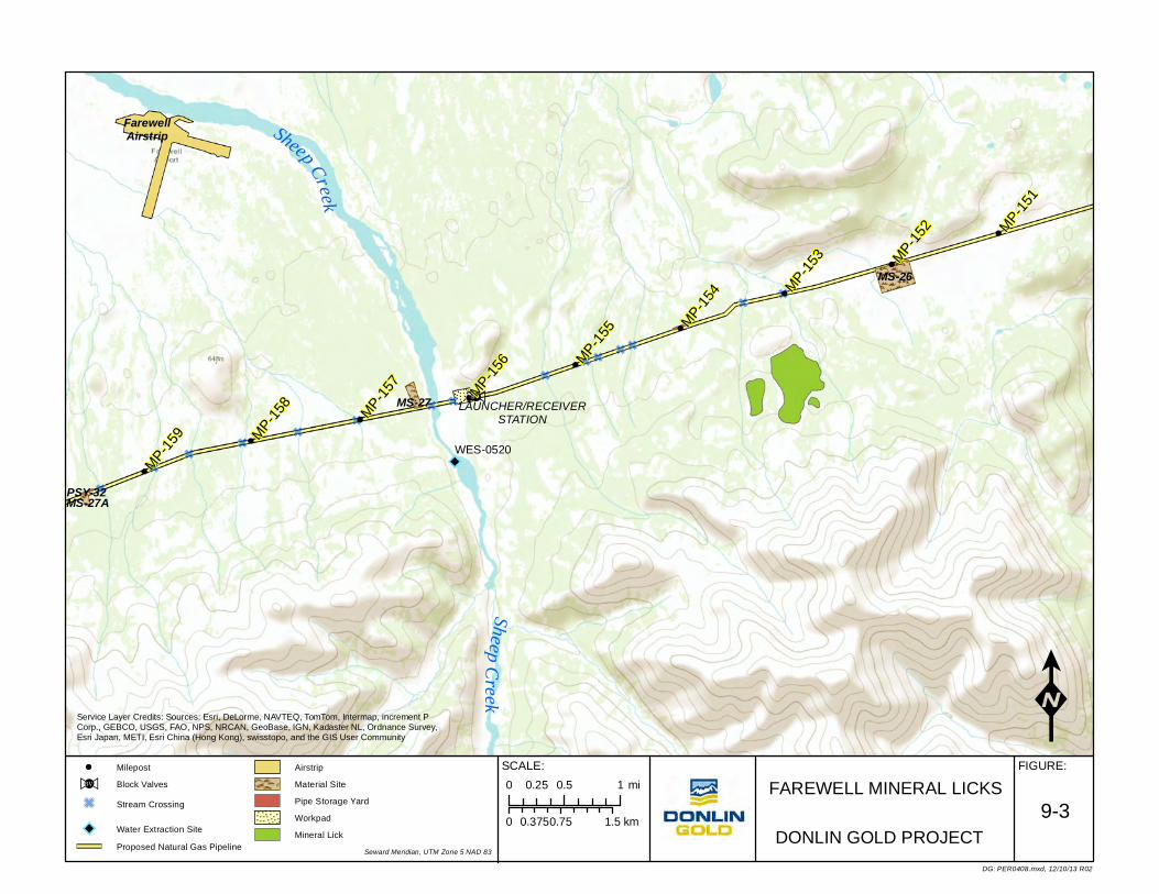
Sheep Creek
SheepCreek
MP-153 MP-1
52
MP-157
MP-159
MP-156
MP-151
MP-158
MP-155
MP-154
FarewellAirstrip
MS-26
MS-27A
MS-27
PSY-32
LAUNCHER/RECEIVERSTATION
WES-0520
FAREWELL MINERAL LICKS
0 0.75 1.50.375 km
FIGURE:SCALE:
KDG: PER0408.mxd, 12/10/13 R02
DONLIN GOLD PROJECT9-3
Milepost
>!BV Block Valves
G Stream Crossing
Water Extraction Site
Proposed Natural Gas Pipeline
Airstrip
Material Site
Pipe Storage Yard
Workpad
Mineral Lick
0 0.5 10.25 mi
Service Layer Credits: Sources: Esri, DeLorme, NAVTEQ, TomTom, Intermap, increment PCorp., GEBCO, USGS, FAO, NPS, NRCAN, GeoBase, IGN, Kadaster NL, Ordnance Survey,Esri Japan, METI, Esri China (Hong Kong), swisstopo, and the GIS User Community
Seward Meridian, UTM Zone 5 NAD 83

Plan of Development Donlin Gold Project Resource Values & Environmental Concerns
Donlin Gold 9-28 December 2013
Potential Effects Some long-term effects on wildlife in association with the pipeline are expected. Some potential effects on wildlife are expected to be temporary and localized. Probable effects include:
• Temporary disturbance/displacement during construction resulting in short-term changes in habitat use and short-term changes in behavior.
• Habitat loss or alteration resulting from construction activities. • Clearing of the ROW has some potential to increase access along areas of the
route during the winter season and this could result in some long-term changes in patterns of subsistence use and increased user conflict, especially in light of ongoing conservation concerns associated with moose and salmon in the area.
These impacts generally would affect individual animals. Wildlife populations are not expected to be affected negatively.
Mitigation Mitigation measures incorporated in the proposed pipeline project for wildlife include:
• Restoring habitat through restoration and reclamation of affected vegetation. • Avoiding locating facilities in sensitive wildlife habitats to the maximum extent
practicable. • Scheduling construction activities to avoid sensitive periods in the life cycle of
wildlife to the extent practicable recognizing that the construction schedule must also take into consideration seasonal conditions to facilitate construction and to reduce other impacts.
• Verifying that construction camp operations and facility construction activities comply with measures that avoid attracting wildlife which may include but not be limited to fencing camps, incineration of putrescible wastes, proper storage of food and other materials to avoid access by wildlife and prohibitions on animal feeding.
• Adopting motor vehicle and aircraft procedures that minimize disturbances to wildlife.
• Identifying and then avoiding or minimizing situations in which wildlife may be killed in defense of life or property.
• Work with ADF&G and other agencies to mitigate increased access for moose hunting and other local subsistence activities to the extent feasible and practicable including verifying that new airstrips constructed for pipeline installation are reclaimed in a manner that renders them unusable.
• A Wildlife Avoidance and Human Encounter/Interaction Plan would be developed and implemented for construction and operation to avoid impacts to subsistence species to the extent possible.
• Donlin Gold and Contract person would not be allowed to hunt while in the field associated with construction, operation, maintenance or termination activities.
9.2.12 Special Status Species Federal sensitive species and State of Alaska species of special concern that may occur or that have suitable habitat in the vicinity of the pipeline study include the following:
• BLM sensitive species. The BLM lists Olive-sided Flycatcher, Gray-cheeked Thrush, Townsend’s Warbler, Blackpoll Warbler, Trumpeter Swan, and Rusty
Plan of Development Donlin Gold Project Resource Values & Environmental Concerns
Donlin Gold 9-29 December 2013
Blackbird as avian sensitive species whose habitat occurs in or near the pipeline corridor. The Canada lynx is the only non-avian sensitive species whose habitat occurs in the vicinity.
• State of Alaska species of special concern. The state lists American Peregrine Falcon, Northern Goshawk, Olive-sided Flycatcher, Gray-cheeked Thrush, Townsend’s Warbler, and Blackpoll Warbler as species of special concern whose habitat occurs in or near the pipeline corridor.
• USGS Boreal Partners in Flight’s Priority Species for Conservation. The only species with this designation whose habitat occurs in the study area is the Great Gray owl. Three occupied Great Gray owl nests have been identified in the pipeline corridor.
• Audubon Alaska’s Alaska Watch List. The only raptor species that Audubon Alaska has classified on its Watch List is the Northern Goshawk.
Potential Effects The effects of the pipeline project are expected to be temporary and localized. Effects would be the result of construction activities along the alignment and limited as approximately two-thirds of construction would be done during the winter months with the overall construction period anticipated to be no more than 3 to 4 years.
Plant Species As discussed in Section 8.1.10, information regarding the presence of rare plant species in the pipeline area will be addressed in more detail after addition field studies and during development of specific design and construction plans. During field work, several observations of species tracked by the AKHNP were made. The state rank levels (S-rank, with species with a state rank level below “S4” are considered rare and are tracked by the AKNHP) vary among the species, but the global rank level is consistent for these plant species and indicates the species are widespread and abundant in locations outside Alaska. These include the following:
• Bristleleaf Sedge (Carex eburnean) S3 • Little Prickly Sedge (Carex echinata) S1, S2 • Fowl mannagrass (Glyceria striata) S3 • Elephanthead lousewort (Pedicularis groenlandica) S2
Federal sensitive species and State of Alaska species of special concern may occur or have suitable habitat in the vicinity of the pipeline route.
That portion of the pipeline route through the Alaska Range is remote and has not been impacted by annual use as significantly as where the route is located in closer proximity to trails or other disturbed areas that may have the potential for greater exposure to invasive species. The route through the SFSGR follows the Pretty Creek Road ROW, an area previously disturbed and still used.
Potential Effects The effects of the proposed pipeline project would be temporary and localized and would be the result of construction activities. Some plants may be destroyed as a result of construction activities. Some species may be temporarily disturbed or displaced as a result of construction.

Plan of Development Donlin Gold Project Resource Values & Environmental Concerns
Donlin Gold 9-30 December 2013
Mitigation Mitigation options, if required, would be developed collaboratively with the appropriate agencies upon their review of the proposed pipeline project. Donlin Gold would emphasize prevention and early detection and rapid response in managing invasive species.
9.2.13 Visual Resources Visual resources are defined as the land, water, vegetation, animals, and structures that are visible on the land. The proposed ROW would pass through areas that contain visual resources including, but not be limited to, the Alaska Range, the Skwentna River Valley, and Rainy Pass. Reasonable effort would be made to minimize visual effects, particularly in areas of high scenic and visual value. Along the entire corridor, most background views are untouched by human activity.
The ROW would be cleared within sight of the Iditarod Trail corridor in some areas and would be visible from ridgelines along the route and to commercial passenger air flights and charter aircraft flights for hunting, fishing, flightseeing, and media and spectators following overland events on the Iditarod Trail.
The pipeline corridor would be located in remote areas somewhat more difficult to access on the ground. The corridor would still be visible from aircraft flying overhead through the area. Any permanent facilities that would be required for operation would be seen. Many of these activities and much of the associated disturbance to the ROW would be transitory in nature because construction operations would move at a pace of approximately 3,000 to 5,000 ft (914 to 1,524 m) per day.
On a long-term basis, disturbance caused by construction would be visible for varying lengths of time, depending on soil conditions, terrain features, and vegetative cover. Because the proposed pipeline would be buried for nearly its entire length (two short, aboveground sections are located at the two fault crossings at approximately MP 7.5 and MP 148.), the pipeline itself would not be visible and vegetative cover would be reestablished, even though the linear corridor would continue to be identifiable for many years, even after termination and the corridor vegetation has matured.
Except around aboveground valves, signage, and any other permanent facilities, revegetation of the cleared ROW would begin as soon as construction is complete, and vegetative cover would be maintained, reducing project-related visual effects as new growth covers exposed soils.
Aesthetics involves value judgment; some visitors might have an adverse reaction to views of the pipeline corridor or aboveground, related facilities, while others would not. Donlin Gold would work with the agencies in an effort to minimize and/or mitigate effects on areas of high scenic and visual values and expects to create only intermittent and localized effects on visual resources. Donlin Gold would specifically work with the appropriate agencies to minimize to the extent feasible visual impacts of the proposed pipeline project in the limited areas where it crosses or is in proximity to the Iditarod Trail. Donlin Gold would attempt to cause only temporary, localized effects on existing visual resources during clearing and construction through the presence of machinery and personnel and, potentially, through increase in dust in some locations. Long-term aesthetic effects would decrease as soon as reclamation occurs and the impacts to the ROW have been mitigated, although some visual evidence of construction may persist.
Plan of Development Donlin Gold Project Resource Values & Environmental Concerns
Donlin Gold 9-31 December 2013
BLM has started its resource management planning process which includes federal lands crossed by the proposed pipeline route. See Section 9.2.16.
Potential Effects Once constructed, most of the pipeline would be buried except for aboveground facilities including the metering station, compressor station, the repeater station for the fiber optic system, the pigging station, and MLVs. These facilities would not be visible from any adjacent public roads, as there are none except the Pretty Creek Road. The ROW would be visible in some locations associated with the SFSGR and Iditarod Trail, from higher elevations, and to the public able to access these areas, primarily in the winter or from flying overhead. Following construction the visual effects of the pipeline itself would be minimal even though the ROW would remain visible; however, the reclaimed portion of the temporary ROW would eventually establish a vegetative cover similar to the adjacent area as it matures. The permanent ROW would be reclaimed as well but would be cleared of larger plant material to facilitate surveillance and monitoring and to allow for maintenance activities.
Mitigation Efforts would be made to minimize visual effects, particularly in areas of high scenic and visual value but certain regulatory requirements must be adhered to such as for markers, signs and the locations of valves within certain limits. In such cases Donlin Gold would address construction impact concerns on a case-by-case basis to the extent reasonable and practicable as most of the pipeline is buried and the ROW would be reclaimed.
These plans would include:
• Reviewing the success and practicability of measures that were taken to prevent or minimize significant adverse effects on visual resources on other projects, including the TAPS, the Dalton Highway, the Elliott and Parks Highways, and the Anchorage-to-Fairbanks Intertie, and incorporating successful measures into the design and location of the pipeline where reasonable and appropriate.
• Coloring aboveground facilities with matte-finish (low level of reflectivity) earth-tone paints that blend into the natural landscape at each location during the months of June, July, and August (summer colors), including aboveground sections of the pipeline, appurtences, ancillary equipment, and associated valves at the remote MLV locations. Fencing and gates would also be finished in a manner to reduce visual impacts by using coated/colored fencing/gates.
• Where clearing of brush and shrubs is applicable in the permanent ROW only the minimum required for safety, monitoring and surveillance and maintenance would be done.
• Reclaiming the construction ROW in a manner that facilitates reestablishment of natural vegetation.
• Use any salvaged native plant materials and topsoil removed from the construction footprint for redistribution on disturbed areas when and where feasible.
• Use, if and when available, of existing disturbed areas to the maximum extent practicable for temporary construction activities such as construction camps, material stockpiling, pipe jointing, and pipe bending, minimizing the location of facilities, new material sites, and construction material stockpiling in places that have special visual resource values that would be visible to the general public.

Plan of Development Donlin Gold Project Resource Values & Environmental Concerns
Donlin Gold 9-32 December 2013
• Blending the pipeline system into the natural setting to the extent practicable when crossing places that have high visual resource values.
• Use of revegetation species that are appropriate for the general area. • Regrading construction disturbances to a condition that blends with surrounding
terrain and surface drainage patterns. • Monitoring reclaimed, disturbed construction areas and taking remedial action
where expected revegetation success is not achieved.
9.2.14 Social and Economic Social and economic studies have focused on Calista lands, which are crossed by the western portion of the pipeline corridor. Some baseline information on socioeconomic conditions in villages on Doyon Regional Corporation lands in the upper Kuskokwim River drainage was collected during the socioeconomic studies. The Calista Region encompasses an area of 58,211 square miles (150,766 km2) and includes nearly 50 communities. This region is one of the most economically depressed in the United States. Stable employment, services, and health care are difficult to obtain in the small, isolated rural communities, contributing to a gradual outmigration of people to larger communities.
Elevated levels of substance abuse and domestic violence have been recorded in many communities in the region. Subsistence activities are an important source of food and an important part of the cultural identity in the region. Some small businesses that provide services to the local communities create some employment, but regular, full-time jobs are in high demand and largely limited to government and social organizations. The Donlin Gold project, including the pipeline, has the potential to provide an opportunity for qualified individuals to find employment.
Donlin Gold will undertake a Health Impact Assessment for the proposed project.
Potential Effects
• Increased employment opportunities and workforce development • Changes in employment and income levels • Construction may temporarily disrupt lodge operations and guiding activities as a
result of seasonal impacts but expected to be minimal
Mitigation
• Assist with developing training programs for local area residents so that some can be employed during construction and O&M.
• Whenever reasonably possible schedules would recognize subsistence hunting and fishing times and locations with the understanding that construction activities must also take advantage of seasonal and environmental conditions as well to minimize construction related environmental impacts. Donlin Gold would engage with lodges and guides in advance of construction to coordinate activities.
9.2.15 Subsistence Villages in the vicinity of the proposed pipeline corridor are shown in Figure 9-2.
Subsistence activities in the western portion of the pipeline corridor in the lower Kuskokwim River region primarily include harvesting of salmon and resident fish; hunting of moose, bear, caribou, and waterfowl; and gathering of berries, native plants, and firewood. Residents from Nikolai and Lake Minchmina travel in the area and use the South Fork of the

Plan of Development Donlin Gold Project Resource Values & Environmental Concerns
Donlin Gold 9-33 December 2013
Kuskokwim River and Windy Fork to harvest fish. They also travel towards the mountains to hunting camps, potentially crossing the pipeline ROW. Camps in the mountains are used both for subsistence and guiding by Nikolai residents, per ADF&G.
Residents in the area along an approximately 80-mile (129 km) segment of the pipeline nearest the mine have harvested a wide range of resources (salmon and resident fish, moose, bear, caribou, waterfowl and berries) from the area traversed by the pipeline corridor. The corridor also transits an area historically and currently used for sheep hunting.
The areas surrounding the proposed pipeline corridor east of the Alaska Range are used most intensively for subsistence moose harvesting; the area around the eastern terminus is also used by Tyonek residents for subsistence berry picking.
Potential Effects
The effects of the pipeline project during construction on subsistence wildlife species and subsistence activities are expected to be temporary and localized. However, construction of the pipeline through remote areas of the Alaska Range may increase the potential for people to access areas that are currently less accessible by snowmachine. This could result in increased hunting and fishing pressure and user conflicts in the area. Impacts from the construction and installation of the pipeline could affect local subsistence lifestyles. Most hunting in the Alaska Range is guide related.
During operation of the pipeline there would be periodic route surveillance, inspection and monitoring by aircraft flights which should have minimal impact of subsistence. Other non-project related aircraft may fly along the pipeline ROW in route to their destination which should also have minimal impact. The temporary airstrips built for construction purposes would be reclaimed and rendered unusable following construction.
Mitigation Donlin Gold would use current information and traditional knowledge to identify locations and times when subsistence activities occur, and avoid or minimize work or impacts during those times and in those areas to the extent practicable, recognizing that if it cannot be accomplished the duration of the construction period for the pipeline is short-term.
A Wildlife Avoidance and Human Encounter/Interaction Plan would be developed and implemented for construction and operation to avoid impacts to subsistence species to the extent possible.
If possible, Donlin Gold would schedule preconstruction and construction work to avoid or minimize to the degree practicable interference during peak periods of subsistence activities in the affected area.
9.2.16 State or Federal Projects There is no known major state or federal project in or near the proposed ROW. However, the ADNR has identified the Happy River Remote Recreation Staking Area near the proposed ROW within T22N R18W and T22N R17W Seward Meridian. ADNR has issued its Final Finding and Decision in the process of evaluating the proposed action to hold a competitive coal lease sale for approximately 13,160 acres (5,326 ha) of land in the Canyon Creek area, south of the Skwentna River in townships T19-21N, R13 and 14W, Seward Meridian. The proposed sale area lies along the southeastern flank of the Alaska Range, on the lower east flank of Dickason Mountain approximately 18 miles (29 km) southwest of the

Plan of Development Donlin Gold Project Resource Values & Environmental Concerns
Donlin Gold 9-34 December 2013
nearest community of Skwentna, and approximately 6 miles (9.7 km) southwest of Shell Lake.
The BLM is undertaking development of the Bering Sea- Western Interior Resource Management Plan having published its Notice of Intent (NOI) in the Federal Register July 18, 2013. The NOI began the 150 day public scoping period that will run through December 16, 2013. The scoping report is scheduled to be available in Spring 2014. The Bering Sea-Western Interior planning area includes all lands south of the Central Yukon watershed to the southern boundary of the Kuskokwim River watershed, and all lands west of Denali National Park and Preserve to the Bering Sea, including Saint Lawrence, Saint Matthew and Nunivak islands.
9.2.17 Recreation Activities
Important tourism opportunities and recreation resources are located along the proposed pipeline route. No new public vehicular access is expected, however, the pipeline corridor would become an access route for snowmachine use because the ROW does not create an exclusive right of surface use for Donlin Gold, and access after construction would not be prohibited except as established by the applicable landowner.
Existing public access would be retained. Preconstruction and construction activities may cause short-term adverse effects on tourism and recreation. While users of the remote areas near the pipeline route for hunting and recreational purposes may have an expectation for a quiet and remote, undisturbed experience, there would be overflights from helicopters and fixed wing aircraft associated with field work and pipeline construction, and not as frequently during operation and maintenance activities.
Some long-term effect on tourism or recreation is expected once construction is complete since the increased number of recreational users potentially accessing areas via the pipeline route increasing the potential for user conflicts and impacting regional resources.
Potential Effects Distribution of construction supplies and equipment for the project would be by barge traffic up the Kuskokwim River, by highway and then ice road, by aircraft, or by barge to Beluga then along the ROW. Within the project area scheduling preconstruction and construction activities to avoid or minimize to the degree practicable interference during the peak tourist and recreation seasons would greatly reduce any adverse effects. However, much of the recreational activity would occur in the same seasons that construction activities would occur and thus some effects would be unavoidable. Some long-term effect on recreation is expected as a result of the pipeline corridor once construction is complete.
Mitigation Mitigation measures for tourism and recreation use areas include:
• Avoiding areas with tourist-related facilities if reasonably possible • Minimize creating new public access to remote areas • Minimize impacts to existing natural landscape to the extent practicable • Scheduling preconstruction work to avoid or minimize interference during peak
periods of tourism and recreational activities in the affected area

Plan of Development Donlin Gold Project Resource Values & Environmental Concerns
Donlin Gold 9-35 December 2013
• Early and continuing consultation with the public, and tourism and recreation businesses
• In areas where preconstruction and construction activities would impact existing access routes Donlin Gold would provide alternate access or allow for controlled access within or across the construction area
• Work with the landowner to address concerns regarding access provided by the pipeline corridor because the ROW proposed for the pipeline does not create an exclusive right of surface use for the applicant - access after construction will not be prohibited unless specifically established by the landowner
• Airstrips would be rendered unusable and reclaimed when no longer needed
The major seasons for recreation tend to be focused on the Iditarod races in March, access for March bison hunt, salmon fishing in spring and early summer, and big game and waterfowl hunting in fall. Adverse effects can be minimized to the extent that preconstruction and construction activities occur primarily during winter. As noted above Donlin Gold recognizes that recreational activities would also occur in periods that coincide with construction activities and would attempt to mitigate conflicts as reasonably possible.
9.2.18 Wilderness The proposed pipeline route does not cross any designated wilderness areas. Formal BLM Lands with Wilderness Characteristics inventories are underway for BLM lands included in the planning process for the Bering Sea Western Interior Resources Management Plan, which includes a portion of the proposed pipeline area.
Potential Effects Construction communications towers located at construction camps for camp and construction communications would be temporary and would move as camps relocate to new campsites. Any impact related to the towers would be short term and limited to the period of project construction. Height of the towers may vary but generally would not exceed 50 ft (15 m). These towers are not associated with the fiber optic cable installation that is proposed.
Overflights from helicopters and airplanes could have impacts on tourism as well as wildlife, even though such flights would be seasonally limited and more confined to the proposed pipeline corridor.
Mitigation Donlin Gold would minimize number of flights to the extent practicable and schedule necessary flights during such times to reduce any impacts on wilderness areas.
Although communication towers would be used during construction, there existence would be temporary and would be constructed only to the height necessary to provide for project communications.

Plan of Development Donlin Gold Project Stabilization, Rehabilitation and Reclamation
Donlin Gold 10-1 December 2013
10.0 Stabilization, Rehabilitation and Reclamation A Stabilization, Rehabilitation and Reclamation Plan would be developed during final project design to address all disturbed areas associated with pipeline and related facility construction, operation, maintenance and termination including the ROW, new airfields, material sites, campsites, barge landing sites, temporary access roads, pipe storage yards, and other temporary use areas, maintenance sites during operation, and final stabilization, rehabilitation and reclamation at termination. The plan would include but is not limited to the following:
• Soil removal and replacement • Cleanup and reclamation • Stockpiling and use of salvageable growth medium • Disposal of excess spoil and excavated material • Erosion and sediment control • Natural revegetation including site preparation, and seeding as an option if and
where appropriate • Invasive species prevention and management • Limiting access to the ROW to allow stabilization, rehabilitation and reclamation
actions to be successfully accomplished • Inspection and maintenance/monitoring schedule and requirements • Activities occurring during operation and maintenance • Status of temporary use areas following construction • Emergency reclamation situations • Termination and final reclamation • Estimated cost and unconditional guaranty for performance
The Stabilization, Rehabilitation and Reclamation Plan also would identify areas along the ROW or in temporary use areas that may require special attention, such as areas of ice-rich permafrost thaw unstable soils, streambank and streambed restoration, and areas susceptible to erosion.
A range of maintenance measures would be identified to address the potential remediation requirements. One of the most significant impacts to vegetation may likely be scarring from loaded sidebooms lowering-in or making tie-ins. Such damage would be addressed through reclamation and revegetation efforts.
An Invasive Species Prevention and Management Plan would be developed in conjunction with the Stabilization, Rehabilitation and Reclamation Plan. This plan would provide procedures to control the introduction and spread of ISs as part of preparation for construction, construction, maintenance and operation, and stabilization, rehabilitation and reclamation activities. ISs, including aquatic and terrestrial species, can be introduced and spread into an area from the use of airstrips, material sites, and temporary use areas such as pipe storage sites and camps and along the ROW by workers, equipment and materials if not properly addressed.

Plan of Development Donlin Gold Project Stabilization, Rehabilitation and Reclamation
Donlin Gold 10-2 December 2013
10.1 Soil Removal and Replacement
10.1.1 Trench/Right-of-Way In areas where the top organic soil can be separated from mineral soils when the trench is excavated, this material would be recovered and placed as the surface portion of the backfill in the trench. Where this material is either nonexistent or not recoverable, an attempt would be made to place finer-grained soils at the top of the trench backfill to facilitate revegetation. In all cases, the trench would be mounded to account for future settlement of trench backfill to prevent water from ponding over the trench line. The backfilled trench would be monitored after construction to verify that the vegetated mat grows in and erosion of fill or water-ponding above the pipe does not occur.
Crews would clean all construction debris from the ROW and grade and scarify the workpad surface to prepare it for natural plant revegetation, particularly in areas with little or no slope, little potential for significant erosion and adequate natural seed sources or rootstock. Water bars would be constructed on steep, longitudinal slopes to prevent erosion from surface water runoff. All grading would be conducted to drain water away from the trench line. Following preparation, the workpad and trench line would be prepared to promote revegetation of the ROW. Once ROW revegetation efforts take hold, other temporary erosion control measures placed during construction can be removed as appropriate.
In addition to reclamation of the ROW, material sites, pipe storage yards, barge landing areas, airstrips, campsites, and temporary access roads would be re-contoured and reclaimed to an acceptable condition as required by applicable permits and the approved Stabilization, Rehabilitation, and Reclamation Plan. Revegetation of these disturbed areas would proceed in the same manner as in the ROW.
10.2 Drainage and Erosion Control, Clean-up and Reclamation Drainage and erosion control measures, both temporary and permanent, would be implemented along the pipeline ROW in general and at specific facilities such as temporary construction camps, pipe storage yards, material sites, airstrips, and roads. Permanent facilities would also require such measures and would include the metering station, compressor station, fiber optic repeater station, pigging station and MLV locations. The type of control measures used would take into account the following:
• Climate and seasonal impacts of the site • Extent and duration of surface disturbance • Soil conditions such as gradation, thermal condition • Topography (drainage characteristics) • Grading requirements • Local drainage patterns • Future uses of the ROW by the public and wildlife • Environmental conditions (vegetation and wildlife habitat). Structures and
techniques employed to maintain existing surface water and groundwater flow patterns and address potential erosion would be designed and constructed in an effort to:
- Minimize hydraulic soil erosion

Plan of Development Donlin Gold Project Stabilization, Rehabilitation and Reclamation
Donlin Gold 10-3 December 2013
- Minimize thermal erosion and degradation - Minimize disturbance to aquatic and terrestrial wildlife - Minimize siltation of waterbodies and maintain water quality - Maintain fish in all fish-bearing waters - Maintain character of river and stream channels - Minimize impacts on cultural and archeological sites - Minimize visual impacts
A cleanup crew would follow behind the backfill crew and perform all cleanup, rehabilitation and reclamation of cuts when possible, and planned erosion control, during the same season as pipe installation.
A reclamation crew would go back over the ROW during the summer after a winter season to fix any erosion control problems that have developed during breakup, rehabilitate the trench line and working side as needed to facilitate natural revegetation, and then fix any permafrost degradation that may not occur until later in summer. In a summer section, the reclamation crew would follow the cleanup crew during the same summer. This double coverage of erosion control and reclamation efforts in permafrost terrain would provide additional protection of these sensitive areas.
Slash, chips, stumps, or other wooden material including unused tree trunks that was generated during the clearing process would be scattered on the ROW to enhance revegetation and create habitat. Tree trunks used to develop corduroy road beds during construction would be left in place on the workpad surface.
During winter construction, temporary erosion control measures would not be necessary. At the latitudes at which the pipeline is to be laid in winter, the weather would be below freezing from the start of winter until spring breakup. Even when ambient temperatures climb above freezing, or when the sun shines brightly in spring, the ground would remain frozen.
For summer construction, temporary erosion control measures such as sediment barriers (for example, brush berms) and temporary slope breakers would be installed as needed to contain disturbed soils on the construction ROW and to minimize the potential for soil to enter wetlands or waterbodies. After installation, temporary erosion control measures would be regularly inspected and maintained throughout the duration of construction, until permanent erosion control measures have been installed and reclamation is complete. Trench plugs would be used in the trench in hilly terrain to prevent water from eroding the trench bottom. Trench plugs would also be used on each side of waterbody crossings to prevent trench water from entering the stream, river, or wetland.
Temporary slope breakers on summer graded ROWs or workpads would be constructed of soil, brush berms, straw bales (straw bales have the potential to be a source of invasive weeds and would be made from Alaska Certified Weed Free Straw sources if used), or sandbags. Sediment barriers would be constructed of brush berms or sandbags. They would be installed along wetlands, drainages, and streams to prevent sediment-laden water from leaving the ROW. They can also be used at outlets of slope breakers to control sedimentation off the ROW.

Plan of Development Donlin Gold Project Stabilization, Rehabilitation and Reclamation
Donlin Gold 10-4 December 2013
10.2.1 Stabilization of the Backfilled Trench During construction soil would be replaced as soon as practical after the pipeline section is laid down. This would be particularly important during winter construction to reduce the introduction of snow or other precipitation into the trench. In areas of concern (such as wetlands where the native vegetated mat was side-cast during ditch excavation or otherwise segregated) it would be placed as the top portion of trench backfill in the trench, provided the vegetative mat can be salvaged during removal. The backfilled trench vegetation would be monitored after construction to verify the vegetated mat grows in and erosion of the fill above the pipe does not occur.
Stabilization of the backfilled trench may be a multi-year process in some areas, particularly areas with fine-grained, ice-rich soils and wetlands. The proposed pipeline trench may intercept overland flow if not properly addressed and change flow patterns that could erode backfill material from the pipeline trench and could potentially serve to channel water into nearby waterbodies and wetlands. Some areas may be covered with geofabric or other material to prevent erosion. In disturbed areas where the vegetated mat is not available, the surface would be prepared for natural revegetation or seeded with native species at the earliest opportunity to minimize erosion and siltation. In wetland areas where the native vegetated mat is side-cast during ditch excavation, a temporary platform/holding structure may need to be constructed/employed and used as a holding containment device to allow the material to be recovered and put back into place on top of the trench (the preferred method of natural revegetation).
10.2.2 Streambank Protection Erosion or degradation could be caused by breaching of streambanks during construction or future operation and maintenance activities. The techniques that would be used to stabilize streambanks at pipeline crossings would be determined on a site-specific basis.
Erosion control measures for trench excavations performed through streambanks would be applied as soon as the backfill is placed into the trench to complete pipe coverage. Specific materials to be used for erosion control of the streambanks would be determined on a case-by-case basis and identified in the construction plans for each crossing. Conventional, open-cut water crossings would be designed with a gradual approach of the ditch to the streambed from each side, with stress-free sagbends and overbends that extend far enough into the banks to prevent exposure that might be caused by erosion or scour. Where necessary, bank protection would be provided by using geotextile matting, riprap armoring, or other appropriate methods including those described in ADF&G’s Streambank Revegetation and Protection: A Guide for Alaska or ADNR’s Plant Materials Center manuals.
10.2.3 Reclamation of Waterbody Crossings This section applies to open-cut, channel diversion, dam-and-pump, and flume crossings. The techniques that would be used to stabilize pipeline crossings of waterbodies would be determined on a site-specific basis.
Backfilling would start promptly after the pipe has been positioned in the trench at the desired depth and as-built by the surveyors. Backfill material would consist of the spoil material excavated from the trench unless otherwise specified in the permits. The waterbody

Plan of Development Donlin Gold Project Stabilization, Rehabilitation and Reclamation
Donlin Gold 10-5 December 2013
bottom contours would be restored as near as practicable to preconstruction condition to allow normal water flow. Trench breakers would normally be installed on slopes adjacent to the waterbodies.
If trench dewatering is necessary for tie-ins, the water would be pumped into a well-vegetated upland area, dewatering filter bag or GeoTextile bag, a straw bale, or other structure designed in a manner to filter the solids and prevent the flow of heavily silt-laden water into waterbodies or wetlands. Dewatering activities would also take into account the seasonal conditions. Collected sediments could be used in reclamation. Trench dewatering would be addressed in the Erosion and Sedimentation Control Plan.
After the waterbody pipe section has been installed and the trench has been backfilled, disturbed areas would be graded to restore preconstruction contours to the extent practical and to allow use of the ROW crossing, if there is one, until it is removed during final cleanup. Waterbody banks that are steep or unstable before construction would be recontoured to a more stable configuration. If there is a potential for significant bank erosion, the disturbed banks would be stabilized with rock riprap or other means, and continued monitoring and maintenance may be required. Jute matting or erosion-control blankets can be installed on the waterbody banks upslope of the riprap or on the entire bank if no riprap is used. The banks and adjacent disturbed areas would be reclaimed as appropriate, and mulch may be applied as needed on slopes. Waterbody banks would be stabilized, and temporary sediment barriers would be reinstalled to minimize sedimentation. Flumes and dams would be removed from the waterbody bed, and permanent slope breakers would be installed on adjacent slopes. Where necessary for access, a temporary access way along the ROW may be left open, delaying the installation of permanent slope breakers across the full width of the ROW until the access is no longer needed. Temporary bridges would be removed after final cleanup and other ROW reclamation activities have been completed, and within the appropriate fisheries construction window for the waterbody that has been crossed. Temporary sediment barriers would be removed after vegetation has become established.
In winter, backfill would be mounded over the trench on crossing approaches to allow for the effects of settlement of the backfill. Slope and trench breakers would be constructed on longitudinal slopes. These berms would be constructed with sand bags or compacted, cohesive soils and placed across the ROW to mitigate or reduce erosion along the pipeline trench and the ROW. On cross-slopes, berms would be oriented to divert water to the downhill side of the ROW.
10.3 Clean-up Crew Functions All cleanup crews would follow the backfill crew during the same season when the pipe is being laid. In winter, the cleanup crew would be the last crew off the ROW and would prepare the ROW for breakup. In summer, the restoration crew would follow immediately behind the cleanup crew. The backfill crew would only do a rough backfill of the trench. This crew would not be involved in pipeline ROW cleanup functions. The cleanup crews following the backfill crew would perform the following functions:
• Pick up and remove all excess materials, tools, skids, and trash from the ROW. • Check for and treat or remove from the project area for proper disposal any
contaminated soils.

Plan of Development Donlin Gold Project Stabilization, Rehabilitation and Reclamation
Donlin Gold 10-6 December 2013
• On ice or snow pads and frost-packed ROW, grade spilled bedding/padding material or gravel for traction or otherwise move it over to the trench line.
• Mound the backfill over the trench to account for potential backfill settlement. • Cut breaks in the mounded backfill to allow for cross-drainage at all known cross-
drainages, as well as a generous allowance for breaks on cross-slopes. Breaks would also be located at trench breaker locations. Even flat ground would have frequent breaks. In permafrost terrain, it is important to prevent the accumulation and/or channelization of flowing water where there was none before.
• In conjunction with the location of trench breakers, place a permanent slope breaker all the way across the disturbed surface. If the ROW is a snow or ice pad or is frost packed, the disturbance would be the trench. If the ROW is graded or a workpad, or if the ice pad has a cut, the slope breaker would include the working side of the ROW.
• Place the salvaged organic material from the trench on top of the backfill. • Remove all temporary bridges or culverts. • On ice or snow pads and frost-packed ROW, remove all ice or snow in drainages
and ice bridges. Slotting of ice bridges on larger streams or rivers would also be effective.
• Patch cuts in ice-rich or thaw-unstable permafrost. Generally, the best technique for this would be to make the cut near-vertical. In forested areas, trees should be cut at ground level and removed. Erosion control measures and extensive silt fencing would be required at the base of the cut. As the ice-rich material melts during summer, the vegetative mat uphill of the cut would start to fall down and lay over the cut. The more the slope melts, the more vegetative mat would tend to lay down to cover and insulate the cut. This would require frequent monitoring and cleanup of melted material within the sediment barriers.
• Restore cuts to original contours. In some areas, cuts in thaw stable material may be used for workpad material on nearby thaw-unstable permafrost. The workpad would be left in place. Therefore, the cut material used to make the workpad would not be restored. Place saved organic material from cuts back on restored cuts.
• Restore streambanks to original configuration unless they are thaw-unstable; if the banks are thaw-unstable, lay them back and patch.
• Install permanent erosion control material on steep slopes subject to erosion near streams or other sensitive areas.
• Install pipeline markers and other signage.
Silt fencing can be used by the cleanup crew, but it would have to be removed or replaced by the restoration crew during the following summer.
10.4 Reclamation Crew Functions The reclamation crews following winter construction would start their work just after breakup. Their first task and top priority would be to identify any areas that need immediate attention. It would be their job to stabilize any erosion that was initiated during breakup. Once the trouble spots have been stabilized, the reclamation crew would make a more methodical progression down the ROW, repairing minor problems and revegetating all disturbed areas. At the end of the season, this crew would check the ROW one last time to verify that the erosion control has functioned properly during the first summer and to repair any bad surface settlement that shows up late in the season.

Plan of Development Donlin Gold Project Stabilization, Rehabilitation and Reclamation
Donlin Gold 10-7 December 2013
Reclamation crews working in summer on winter snow or ice pad and frost-packed ROW areas would walk or use LGP carriers over the ROW when possible but would require considerable helicopter support as well. The restoration crews that go back over the ROW after the cleanup crews would perform the following functions:
• Pick up and remove any excess materials, tools, skids, and trash from the ROW that was missed during winter cleanup.
• Install additional breaks in the mound over the trench as needed. • Reconfigure the mounded material over the trench to fill in any settled areas. • Install additional slope breakers as necessary. • Check all streambanks for erosion. • Revegetate all disturbed areas (includes seed, fertilizer, and mulch as required).
• As required revegetate camp pads, temporary access roads, material sites, and PSYs.
Following completion of each construction contractor’s contractual obligations any responsibility for all further erosion control and reclamation would be passed to operations personnel or another Donlin Gold contractor. The annual reclamation functions and schedule of activities to be performed following construction would be identified as part of the Stabilization, Rehabilitation and Reclamation Plan.
10.5 Natural Revegetation/Seeding Specifications All disturbed sites and exposed soil would be reclaimed concurrent with the activity or as soon as conditions allow. Disturbed sites and exposed soil would be reclaimed using the native sod and topsoil that was removed with supplemental seeding if necessary. Seeding of the disturbed areas would be done in consultation with the BLM and ADNR and following methods or information described in Revegetation Manual for Alaska (Wright 2009), Alaska Coastal Revegetation & Erosion Control Guide (Wright and Czapla August, 2011) or the Interior Alaska Revegetation and Erosion Guide (Czapla and Wright 2012) available through the ADNR, Division of Agriculture, Plant Materials Center, or the Native Plant Revegetation Manual for the Denali National Park and Preserve. These methods would provide the best way to revegetate disturbed areas through natural revegetation or with native plants or seed mixes to limit the potential for colonization by invasive species. Specific requirements would be identified in the Stabilization, Rehabilitation and Reclamation Plan for any plant materials, seeding and appropriate methods for planting and seed application.
10.6 Fertilizer Application of fertilizer would be conducted in consultation with the BLM and ADNR. The standard practices and planning protocols identified in the Stabilization, Rehabilitation and Reclamation Plan would establish when and where fertilizer would be needed, and the adequate volume, type, and quality of fertilizer to be used. As project development proceeds, specific uses would be determined. Fertilizing ground-disturbed areas would be performed as construction and clean-up progresses if and where determined appropriate.

Plan of Development Donlin Gold Project Stabilization, Rehabilitation and Reclamation
Donlin Gold 10-8 December 2013
10.7 Invasive Species Prevention and Management An Invasive Species Prevention and Management Plan would be developed and implemented. The Plan would include procedures that would be developed to prevent the introduction and control the spread of invasive species as well as monitoring requirements as part of preparation for construction, actual construction, operation, maintenance and termination. Invasive species can be introduced and spread into an area from use of airstrips, material sites, and temporary use areas such as pipe storage yards and camps. Prevention occurs before the equipment, gear, and materials are loaded onto barges, aircraft, transport vehicles, etc. intended for use in the project area. This provides the best opportunity to prevent the introduction and spread; minimizing the corrective actions needed should non-native invasive species become introduced and spread because of the pipeline construction, operation, maintenance and termination activities.
Donlin Gold would complete a baseline survey prior to construction to determine the presence or absence of existing non-native invasive species in the project area.
10.8 Limiting Access to ROW Where the proposed ROW intersects existing trails, final grading may include construction of large berms or other means to discourage or direct ATV traffic along or across the ROW which Donlin Gold would coordinate with the appropriate landowner. Applicable signage would also be installed. This traffic also may be limited in some areas by the remote nature of the pipeline route, environmental conditions or landowner requirements. However, it is recognized that regardless of the efforts of Donlin Gold there would still be use or attempted use of the ROW as a route for ATVs, snowmachines and other such vehicles. Where the pipeline corridor intersects major trails, Donlin Gold would work with the landowner and appropriate agencies to develop a plan for management of trail intersections if necessary. Refer to Sections 3.11.2, 8.1.6, 8.1.7 and 9.1. Maintaining traditional access for hunting and fishing for the public is important and Donlin Gold would work with the appropriate landowner to address access management concerns, especially given that there are existing authorizations in some locations.
10.9 Status of Temporary Roads, Culverts and Bridges following Construction
Stabilization, rehabilitation and reclamation would be performed as soon as practicable on temporary roads that require such action, including the access roads associated with East and West Kuskokwim barge landings. All culverts and temporary bridges would be removed and backhauled to be salvaged, recycled, or disposed.
10.10 Status of Temporary PSYs and Campsites All temporary PSYs and campsites would be cleaned and stabilization, rehabilitation and reclamation would be performed as soon as practicable on sites consistent with the approved Stabilization, Rehabilitation and Reclamation Plan and permit requirements.
10.11 Status of Temporary Camp Facilities following Construction All temporary camp facilities would be removed and transported from the proposed project area. Stabilization, rehabilitation and reclamation would be performed as soon as

Plan of Development Donlin Gold Project Stabilization, Rehabilitation and Reclamation
Donlin Gold 10-9 December 2013
practicable on the sites consistent with the approved Stabilization, Rehabilitation and Reclamation Plan and permit requirements. Whenever possible, concurrent reclamation would occur at campsites as camp facilities are moved or no longer needed.
10.12 Status of Temporary Airstrips following Construction Temporary airstrips constructed for pipeline installation purposes would be decommissioned in a way to prevent future use. All temporary airstrips would have all facilities and equipment removed and the sites would be cleaned and stabilization, rehabilitation and reclamation would be performed as soon as practicable on the sites consistent with the approved Stabilization, Rehabilitation and Reclamation Plan and permit requirements. If the vegetative mat was stripped and stockpiled during construction it would be spread and the area prepared for natural revegetation.
10.13 Status of Material Sites following use for Construction All temporary material sites would be cleaned and any equipment or facilities removed from sites and stabilization, rehabilitation and reclamation would be performed as soon as practicable. Material site boundaries would be shaped in a manner as to blend with surrounding natural land patterns. Regardless of the layout of material sites, primary emphasis would be placed on prevention of soil erosion and damage to any vegetation. All material sites would be reclaimed consistent with approved reclamation plans for each site.
10.14 Status of Barge Landings and Port Facilities following Construction Following completion of construction there would be a 5-acre (2 ha) site required in the Beluga area for storing compressor station materials, pipeline materials, truck(s), ATVs and snowmachines for use during operation and maintenance of the pipeline.
The barge landings at East and West Kuskokwim would be removed following construction and the sites stabilized, rehabilitated and reclaimed.
10.15 Disposition of Salvageable Materials at Completion of Construction All salvaged materials from the west side of the Alaska Range would be transported to the Donlin Gold mine site for appropriate handling and disposal. Salvage materials from the east side of the Alaska Range would be transported to Anchorage for salvage, recycle, or disposal. A storage yard would be required in Anchorage to manage and facilitate the salvage, recycle, or disposal of materials brought back to Anchorage.
10.16 Status of Temporary Land Needs following Construction Following completion of the As-Built Survey which would include all facilities that would be required during operation of the pipeline, the temporary lands included in the construction ROW would be relinquished and the permanent ROW established for the operational life of the project. All lands used for temporary construction support would be stabilized, rehabilitated and reclaimed.

Plan of Development Donlin Gold Project Stabilization, Rehabilitation and Reclamation
Donlin Gold 10-10 December 2013
10.17 Pipeline Maintenance Activities Stabilization, rehabilitation and reclamation would be performed concurrent with or as soon as practicable on sites where maintenance activities require such action. The main objective would be to reclaim such areas and to prevent any erosion from occurring.
10.18 Inspection and Monitoring As with most stabilization, rehabilitation and reclamation activities, follow-up inspection and monitoring and reporting are required to identify any necessary adjustments or modifications necessary to meet the objectives of the reclamation.
Success of reclamation would be monitored in two ways. Physical reclamation such as earthwork and growth media application would be checked for excess erosion problems periodically and as soon as possible following major rainstorms and after spring breakup. Remedial action to correct instability would be taken as soon as feasible following detection of substantial erosion or loss of growth media. Vegetative success would be monitored qualitatively by visual inspection on an ongoing basis by Donlin Gold as well as the appropriate agency staff, and quantitatively once per year at the end of the growing season. An inspection and monitoring schedule and performance criteria for vegetative success would be contained in the approved Stabilization, Rehabilitation and Reclamation Plan.
Donlin Gold would seek reduction of the reclamation surety as quantitative data indicate that the established criteria have been met. This would apply to both the reclamation for construction and for final reclamation at termination.
10.19 Unconditional Guaranty for Duties and Obligations
Donlin Gold would provide the BLM and ADNR an unconditional guaranty including a financial guaranty or surety or bond as may be required for the performance of all of Donlin Gold’s duties and obligations in a form approved by BLM and DNR including stabilization, rehabilitation and reclamation during construction, operation, maintenance and termination. Such duties and obligations would be consistent with the approved Stabilization, Rehabilitation and Reclamation Plan, ROW authorizations and appropriate laws and regulations.

Plan of Development Donlin Gold Project Operation and Maintenance
Donlin Gold 11-1 December 2013
11.0 Operation and Maintenance Operation and maintenance of the proposed Donlin Gold Natural Gas Pipeline encompasses all activities after completion of construction, including startup, day-to-day activities necessary for the pipeline to function, and maintenance of equipment, systems, facilities, and pipe. Maintenance includes both preventative maintenance to make sure equipment and systems continue to work efficiently, and corrective maintenance to fix or replace equipment and systems that are not working. Additionally, both operational and maintenance safety and emergencies would be addressed.
11.1 Operation and Maintenance Plan/Manual The O&M Plan/Manual would be prepared in accordance with 49 CFR 192.605. The O&M Plan/Manual would provide written procedures for conducting operations and maintenance activities. The O&M Plan/Manual would be prepared before pipeline operations commence and would be updated periodically as required by the plan.
11.2 ROW Maintenance Schedules The O&M Plan/Manual would provide written procedures for conducting operations and maintenance activities. The O&M Plan/Manual would also include a ROW maintenance schedule which would be prepared before pipeline operations commence.
11.3 Safety A Safety Plan/Program would be developed and implemented for the proposed pipeline project construction, operation and maintenance, and termination. The Safety Plan/Program would identify and address procedures put in place to make sure all operations are performed in a safe manner and that all applicable health and safety laws and regulations are followed to minimize or eliminate hazards to the safety of workers.
As part of Public Outreach, procedures would be developed to provide the public with educational information and information regarding hazards associated with an unintended release and indications that a release has occurred, reporting of release procedures and steps to be taken should a release occur. The program would also provide information regarding access or safety related issues.
11.4 Removal/Addition of Pipe or Equipment during Operation and Maintenance
Removal or addition of equipment or pipe for maintenance purposes could take place at any location (e.g., MLVs). Procedures for these activities would be provided in the O&M Plan/Manual. All procedures would be developed and carried out in accordance with applicable regulations and would follow BMPs.
11.5 Signs and Line and Aerial Markers Signs indicating the company name and emergency phone number would be located on all sides of the fenced, above grade, facilities and be visible to the public. The operations manager would be responsible for ensuring that the signs and markers are maintained.
Line marker signage would be placed in accordance with 49 CFR 192. Carsonite-style markers would be used for all line-marking purposes. The markers would state “Warning,”

Plan of Development Donlin Gold Project Operation and Maintenance
Donlin Gold 11-2 December 2013
followed by “High-pressure Gas Pipeline.” A Donlin Gold telephone number (including area code) at which the company can be reached at all times would be visible on the markers. These markers would also have the “Call Before You Dig” 811 telephone number. Required locations are identified below. See also Section 6.11.
Because the pipeline would cross state, federal, CIRI and Calista lands as well as being located in part within the Matanuska-Susitna borough, additional signage may be required besides that of the pipeline regulatory agencies.
Sign Required Location
Aerial markers Every 1 mile and at each non-facility mainline block valve
Line markers Both sides of rivers Line of sight spacing for all areas Pipeline change in direction
11.6 New and Expanded Access for Operation and Maintenance No new or expanded roads or airstrips are planned and would only be constructed for purposes of operation and maintenance if unforeseen circumstances dictate requesting authorization.
11.7 Inspection and Testing of Pipeline Testing and inspection of the pipeline would comply with federal and state requirements.
Once the pipeline is operational, it would be periodically inspected using in-line inspection tools, such as intelligent inspection pigs. The O&M Plan/Manual would provide details about inspection pigging, and would define the types and frequencies of inspection pigs to be run through the pipeline. The first inspection pig run would establish baseline pipeline conditions. Subsequent pig runs would be scheduled to monitor and detect changes from the baseline conditions. The frequency of the pig runs would be evaluated based on results from previous pig runs and on operating experience and any regulatory requirements.
11.8 Facilities Security The tie-in facility, compressor station, Farewell launcher/receiver site, aboveground fault crossings, and all MLV sites would be fenced and the gates locked. The pipeline terminus facility would not require fencing because it is located at the secure Donlin Gold mine site.
• MLVs and blowdown valves would be kept locked during normal operations. • All blowdown vent caps would be closed and locked during normal operations. • Periodic inspections would be conducted to verify site security.
11.9 ROW Configuration The pipeline typically would be located within a 50-foot (15 m) permanent easement on DNR, CIRI and Calista managed lands and nominally 51 ft 2 inches (15.6 m) on BLM managed lands.
The actual width of the permanent easement for a specific location would be shown on the final surveyed as-built alignment sheets that would be kept on file as well as any changes required for repairs and maintenance that may affect the alignment or the width.
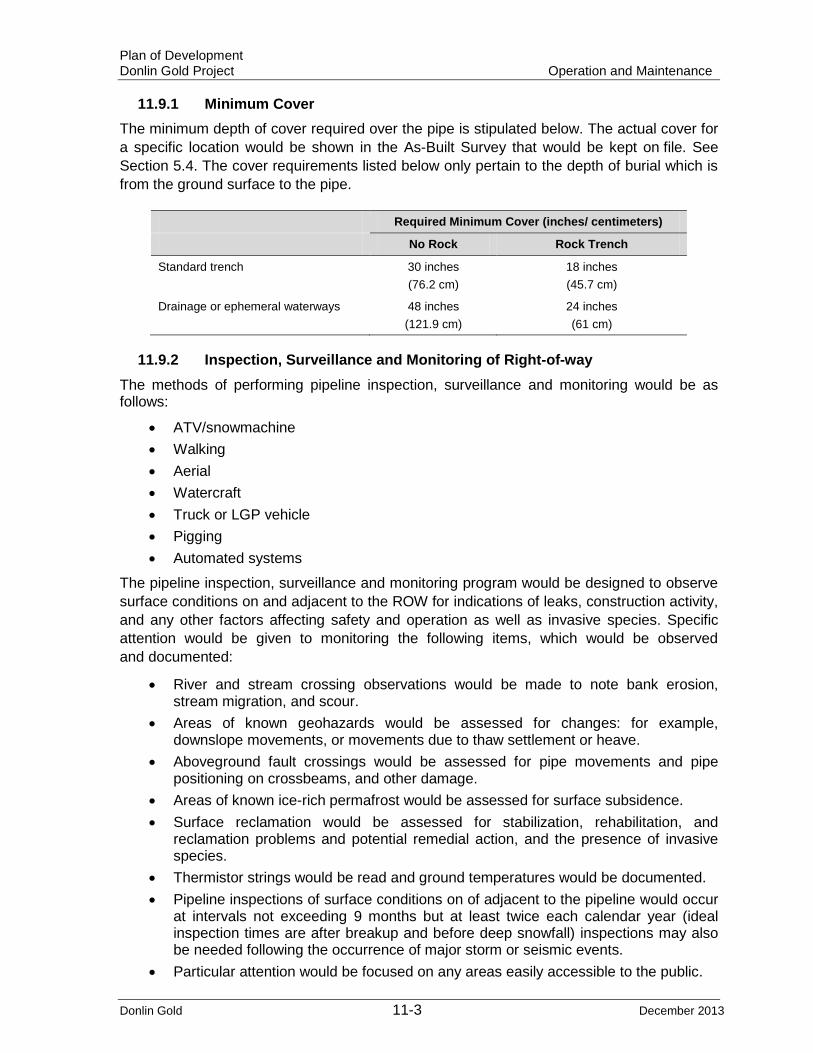
Plan of Development Donlin Gold Project Operation and Maintenance
Donlin Gold 11-3 December 2013
11.9.1 Minimum Cover The minimum depth of cover required over the pipe is stipulated below. The actual cover for a specific location would be shown in the As-Built Survey that would be kept on file. See Section 5.4. The cover requirements listed below only pertain to the depth of burial which is from the ground surface to the pipe.
Required Minimum Cover (inches/ centimeters)
No Rock Rock Trench
Standard trench 30 inches (76.2 cm)
18 inches (45.7 cm)
Drainage or ephemeral waterways 48 inches (121.9 cm)
24 inches (61 cm)
11.9.2 Inspection, Surveillance and Monitoring of Right-of-way The methods of performing pipeline inspection, surveillance and monitoring would be as follows:
• ATV/snowmachine • Walking • Aerial • Watercraft • Truck or LGP vehicle • Pigging • Automated systems
The pipeline inspection, surveillance and monitoring program would be designed to observe surface conditions on and adjacent to the ROW for indications of leaks, construction activity, and any other factors affecting safety and operation as well as invasive species. Specific attention would be given to monitoring the following items, which would be observed and documented:
• River and stream crossing observations would be made to note bank erosion, stream migration, and scour.
• Areas of known geohazards would be assessed for changes: for example, downslope movements, or movements due to thaw settlement or heave.
• Aboveground fault crossings would be assessed for pipe movements and pipe positioning on crossbeams, and other damage.
• Areas of known ice-rich permafrost would be assessed for surface subsidence. • Surface reclamation would be assessed for stabilization, rehabilitation, and
reclamation problems and potential remedial action, and the presence of invasive species.
• Thermistor strings would be read and ground temperatures would be documented. • Pipeline inspections of surface conditions on of adjacent to the pipeline would occur
at intervals not exceeding 9 months but at least twice each calendar year (ideal inspection times are after breakup and before deep snowfall) inspections may also be needed following the occurrence of major storm or seismic events.
• Particular attention would be focused on any areas easily accessible to the public.

Plan of Development Donlin Gold Project Operation and Maintenance
Donlin Gold 11-4 December 2013
• The inspection employees would be alert for vapors, blowing dirt, grass, or leaves near the pipeline; flames coming from the ground or from valves along the pipeline; steady bubbling in a flooded area, wetlands, river, or creek; and dead or discolored vegetation in an otherwise green setting along the pipeline route, all indications of possible leaks.
• The pipeline inspectors would be responsible for noting and immediately reporting pipeline encroachments.
• The ground or aerial patroller would immediately notify the operations center of any condition under which it appears that the public or the pipeline is in imminent danger.
• The operations manager would be responsible for initiating and verifying that the following actions are carried out: - Pipeline inspection procedures are followed by qualified personnel - Prescribed frequencies for pipeline inspection are met - Actions or steps necessary to protect the public and the pipeline as may be
indicated by inspection reports are taken - All surveillance, monitoring, and inspection activities are fully documented
11.9.3 Encroachments ROW encroachments would include any activity on or near the pipeline, such as:
• Road, highway, and railroad construction • Drilling or blasting • Moving heavy equipment across or along the ROW • Plowing or cultivating along or over the pipeline • Housing or commercial developments or other construction activity • Any other activity that could in any way cause personal injury or undue stress and
damage to the pipeline
All encroachments would be communicated immediately to the operations manager, who would investigate the encroachment. Refer to Appendices A and B for existing third-party interests.
11.9.4 ROW Maintenance Clearing For operation and maintenance as well as for safety purposes all or a portion of the 50 ft (15 m) ROW on state and private land and nominal 51 ft 2 inches(15.6 m) ROW on federal land would be cleared of shrubs at approximately 10-year intervals or as required to preserve pipeline integrity and access. To reduce visual resource impacts Donlin Gold would conduct only the minimum amount of clearing necessary. During operation and maintenance any unplanned damage to the vegetation resulting from pipeline activities would be identified and corrective action will be taken to stabilize and rehabilitate the disturbed area, as appropriate for the situation identified and following applicable plans and procedures.
All clearing activities would conform to the BMP requirements of the Invasive Species Prevention and Management Plan to avoid the potential of spreading invasive species in the ROW.
Plan of Development Donlin Gold Project Operation and Maintenance
Donlin Gold 11-5 December 2013
11.9.5 Heavy Equipment Crossing Buried Pipeline ROW Donlin Gold recognizes the potential need for heavy equipment to cross the pipeline ROW at various locations throughout the life of the project. Donlin Gold would not restrict equipment crossing the pipeline provided that some equipment may be required to take appropriate precautions and adequate pipeline protective measures based on location, type/weight of equipment, soils, or other site-specific factors.
11.9.6 Invasive Species Donlin Gold would incorporate early detection rapid response (EDRR) measures for non-native invasive species occurring in the pipeline ROW as provided in the Invasive Species Prevention and Management Plan.
11.10 Pigging Pig launchers and receivers would be designed in accordance with ASME B31.8, except for closures, which would be designed in accordance with Section VIII of the ASME Boiler and Pressure Vessel Code. Pig barrels would be of sufficient length to accommodate internal inspection and data collection tools.
At the pipeline receipt point (MP 0), a launcher assembly would be designed with a compact footprint. The launcher barrel would be configured for above-grade permanent installation with a small surface footprint. The compressor station site at MP 0.4 would have one set of standard design receiver and launcher assemblies. The midpoint launcher/receiver facility would be located near Farewell MP 156. The terminus at the mine would have a pig receiver.
11.10.1 Maintenance Pigging The proposed pipeline would be cleaned as required with standard cleaning pigs. This procedure removes any water, natural gas liquids, or other contaminants from the pipe. Maintenance pigging would occur immediately before any smart pigging operations.
11.10.2 Smart Pigging Inspections The proposed pipeline would be inspected using inline inspection (ILI) tools. The tools would be capable of measuring pipeline curvature, position, bending strain, and dents, and also measuring pipeline wall thickness for purposes of internal and external corrosion detection. The tools may either be a single tool capable of collecting multiple data streams in a single pig run, or multiple, specialty tools in multiple pigging operations. The frequency of the curvature, strain, and corrosion detection inspections would be as required by regulations or as determined appropriate to assess any change in pipe condition in areas where the potential exists for environmental conditions, natural hazards, or changes resulting from pipe installation to impact the integrity of the pipe. Donlin Gold would develop a schedule based on results of surveillance and monitoring or based on specific environmental conditions that may warrant inspection.
11.10.3 Disposal of Operational and Pigging Wastes The pipeline would not generate much waste during operations. There are essentially two types of waste that pipeline operations would generate: compressor oil and natural gas liquids. The compressors would generate used oil as part of the compressor operations

Plan of Development Donlin Gold Project Operation and Maintenance
Donlin Gold 11-6 December 2013
waste stream. Most of this oil would be captured by the coalescing filters on the discharge from the compressors. The oil captured in the coalescing filters would be removed from the compressor station and recycled in South Central Alaska, because there are no provisions for burning the oil at the compressor station in waste oil heaters, and South Central Alaska is the closest populated area to the compressor station. The oil not captured by the coalescing filter would go into the pipeline.
The coalescing filter elements would require replacement at an interval recommended by the compressor skid manufacturer. These filter elements would become part of the compressor station waste stream and would have to be properly disposed of (probably as an oily waste) in South Central Alaska.
The compressor oil that is not captured by the coalescing filters and the liquids that drop out of the natural gas would collect in low spots along the pipeline. It is anticipated that approximately 20 gallons (76 L) of liquid would be generated per year by pipeline operations. This estimate is based on Cook Inlet gas that is currently flowing in the BPL that would supply the proposed Donlin Gold pipeline. The estimated volume of liquid generated would change if the supply gas composition changes.
The liquid would be cleared from the pipeline via pigging operations. The frequency of pigging operations would determine how much liquid is generated. The liquid would be pushed in front of the pig and transferred from pig receiver to pig launcher along the line until it reaches the terminus of the pipeline, where it would be collected in a vessel. It is assumed that this liquid by volume would be essentially insignificant to the volume of waste oil generated at the Donlin Gold mine site. Because the liquid would be either water or a liquid hydrocarbon, it can be placed into the waste oil recovery system at the mine and burned along with the mine waste oil.
11.11 Cathodic Protection and Corrosion Control The proposed pipeline would be surveyed at least once each calendar year, but at intervals not exceeding 15 months, to determine whether cathodic protection levels are adequate. The degree of cathodic protection would be controlled to prevent damage to the protective coating of the pipe.
• All pipeline test site corrosion survey data would be analyzed to verify that potentials meet minimum standards of compliance.
• Atmospheric corrosion surveys would be conducted on each pipeline and facility every 3 years.
• Non-critical interference bonds would be checked at least once each calendar year, at intervals not exceeding 15 months. - When low pipe-to-soil potentials are found during cathodic protection surveys,
remedial measures would be implemented.
The cathodic protection system would be operational as soon as possible after commissioning and startup of the proposed pipeline. The design, installation and implementation would meet all regulatory requirements to assess the adequacy of the cathodic protection system.

Plan of Development Donlin Gold Project Operation and Maintenance
Donlin Gold 11-7 December 2013
11.12 Valves All valves in the proposed pipeline system would be inspected at least once each calendar year, but at intervals not to exceed 15 months. Specific valves may require inspection at more frequent intervals. All inspections would be documented as part of the maintenance record.
• At intervals not exceeding 7 1/2 months, but at least twice each calendar year, each MLV, including related blowdown valves that might be required during an emergency, would be inspected to determine whether it is functioning properly.
• All valves outside a secured facility would be locked to prevent unauthorized operation and vandalism. Certain valves inside secured facilities may be locked, based on the direction of the operations manager.
• A preventive maintenance program conforming to the requirements of USDOT 49 CFR 192.745 would be followed for each valve and valve operator (if applicable) that might be needed in an emergency.
11.12.1 Access to Values There would be four facility locations at fixed block valve locations: the BPL tie-in, the compressor station, the Farewell launcher/receiver site, and the pipeline terminus at the Donlin Gold mine site. The valves located at the BPL tie-in, the compressor station, and the pipeline terminus would be able to be remotely operated, function as ESD valves, and be automatically operated by a SCADA system. The ESD valves would also be able to be manually operated by activation of an ESD switch at any of the three sites and be manually closed by an operator onsite if necessary.
The remaining 16 MLV locations that would not be associated with pipeline facilities would have valve operators, small-bore piping, and associated valves positioned aboveground. All of these valves would be manually operated and accessible by helicopter or depending on season ATV/snowmachine.
11.13 Overpressure Safety Devices At intervals not exceeding 12 months but at least twice each calendar year, each pressure-limiting device, relief valve, rupture disc, pressure regulator and other item of pressure control equipment would be subjected to inspections and tests to determine that it meets the following criteria:
• The items are in good mechanical condition • The item is adequate from the standpoint of capacity and reliability of operation for
the service in which it is employed • The item is set to function at the correct set pressure • The item is properly installed and protected from dirt, liquids, and other conditions
that might prevent proper operation
11.14 Smoking or open Flames “No Smoking or Open Flame” signs would be placed where there is a possibility of leakage of a flammable liquid or presence of flammable vapors.
Open-flame torches and welders would be used only by qualified personnel and in accordance with Donlin Gold hot work procedures.

Plan of Development Donlin Gold Project Operation and Maintenance
Donlin Gold 11-8 December 2013
11.15 Pipe Movement Engineering personnel would be consulted before any movement or relocation of the pipeline. Appropriate design and engineering plan approvals would be obtained prior to plan execution.
Post construction modification to the alignment and ROW width would require additional authorization and survey modification.
11.16 Normal Operating and Maintenance Procedures Review At intervals not exceeding 15 months but at least once each calendar year, the pipeline operations manager would:
• Review the normal O&M procedures with other operating personnel to determine their applicability, use, and effectiveness.
• Review pipeline facilities to determine whether there are areas that would require an immediate response by operating personnel to prevent hazards to the public if these facilities were to fail or malfunction.
Permits and Environmental Compliance Program To facilitate compliance with the safeguards and stipulations of the ROW authorizations, all contractors would be pre-qualified to verify that they have an Operations Integrity Management System in place. In addition, Donlin Gold would implement a Quality Management Program that would:
• Apply to and remain in effect during construction, operation, maintenance and termination.
• Identify the processes needed to be undertaken and the methodologies required to effectively implement the processes.
• Dedicate the resources required to support the operation and monitoring of the processes.
• Monitor, measure, and analyze processes and implement corrective actions to processes if necessary.
The Quality Management Program would include a Quality Manual and Quality Control Plan including policies and objectives. Donlin Gold, including its agents, employees, and contractors would comply with the approved Quality Management Program. This program in conjunction with the Permits and Environmental Compliance Program would serve to identify any potential issues and verify that all work is performed in a manner to maintain the quality of the pipeline and related facilities, and to make sure all work is performed in accordance with relevant permit, lease, and other approval stipulations.
11.17 Construction Records In accordance with 49 CFR 192, all drawings, documentation, and procedures for design information would be approved by Donlin Gold and kept in the pipeline design file for the life of the pipeline.
At a minimum, the following would be kept for the life of the project:
• All drawings, documentation, and procedures for design information • Records of approval of changes in design information in construction drawings and
documents

Plan of Development Donlin Gold Project Operation and Maintenance
Donlin Gold 11-9 December 2013
• Manufacturing test reports for pipe and other materials • All inspection and construction records related to the design information
There may be a need for design changes in the field during the actual construction process based on the conditions encountered in the field. Field design changes would be documented on the drawings and in the specifications. Procedures would be developed and used during project construction and operation. Design changes are required to be approved, in writing, by the Donlin Gold project manager.
Physical information would be obtained to accurately locate and inventory new or changed facilities and would be included in existing maps and drawings. The basic information recorded would be:
• Pipe size, diameter, wall thickness, grade, type, and manufacturer • Location of each weld • Pressure test information • Pipeline stationing • Pipeline elevation • Pre-startup location of pipe on fault crossing members • Location of attachments to pipeline (for example, valves, fittings, and anodes) • Trench depth, where applicable • Length of pipe used • Any unusual features of the ROW • Location and identification of all major facilities • All crossings of public roads, railroads, rivers, buried utilities, and foreign utilities • Date put in service
This information would be retained for the useful life of the facility.
11.18 Operations Records The following O&M records would be maintained:
• Records of communications • Personnel training records • All records necessary for the original establishment of the maximum allowable
operating pressure (MAOP) and any subsequent changes in the MAOP (current MAOP information would be maintained in revisions of the O&M Plan/Manual)
• Records of repair and maintenance • Startup and shutdown records • Daily operating logs indicating:
- The pressures and temperatures for the originating gas receipt point, compressor station, gas delivery point, and any unusual operations of a facility. These records would be kept for at least 3 years.
- Any unusual operations of a facility - Pressure and temperatures at the BPL custody transfer meter, the compressor
station, and the gas delivery point at the mine
• Inspection and test reports for the useful life of the pipeline system
Plan of Development Donlin Gold Project Operation and Maintenance
Donlin Gold 11-10 December 2013
• Records of ROW inspections • Encroachment records
- A foreign line crossing report would be made whenever the pipeline crosses another pipeline or utility. The operations manager would verify that a foreign line crossing report form is completed and is routed as indicated on the form. Each responsible employee would carry copies of the form. This form would be completed and the bottom portion given to the encroaching party.
• Records of corrosion testing of bare pipe not cathodically protected (5-year surveys) • Records for survey of all pipelines at least once each calendar year, but with
intervals not exceeding 15 months, to determine whether cathodic protection levels are adequate. Field readings would be recorded on the pipe-to-soil potential survey form.
• Records of inspections of exposed, buried pipeline for external corrosion (whenever exposed)
• Records of internal corrosion monitoring tests (semiannually) • Records of inspections of internal surface of pipe when pipe is removed for
evidence of internal corrosion (whenever pipe removed) • Records of valve inspections
- Records of inspection, partial operation, and lubrication information for valves. Any repairs or unusual conditions would be noted
- Records of the MLV preventive maintenance program conforming to the requirements of USDOT 49 CFR 192.745 that would be followed for each block valve and valve operator (if applicable) that might be needed in an emergency.
• Records of overpressure safety device inspections • Records of pigging operations (maintenance and inline inspection tool surveys). • Records of pipe movement • Public education records • Records of distribution of pamphlets to and liaison activities with local emergency
groups and public utilities
11.19 Drug Testing Donlin Gold’s drug and alcohol policy will be followed at all times by Donlin Gold and contractor personnel associated with pipeline operations and is compliant with USDOT requirements outlined in 49 CFR 199.
It is the policy of Donlin Gold to provide a work environment that is free of the use, sale, possession, or distribution of illegal drugs or the improper or abusive use of legal drugs or alcohol and to require employees to perform all company-related job duties, either on or off company premises, without the presence of illegal drugs, alcohol, or inappropriate legal drugs in their systems.
The objective of this policy is to ensure a safe, healthy, and work-efficient environment for Donlin Gold employees, business invitees, and the public at large. This objective includes ridding the workplace of illegal and potentially dangerous substances, paraphernalia, and persons who might have an adverse effect on Donlin Gold employees or business. Donlin Gold management uses every reasonable measure to maintain such an environment.

Plan of Development Donlin Gold Project Operation and Maintenance
Donlin Gold 11-11 December 2013
11.20 Industrial Waste and Toxic Substances near ROW The proposed pipeline operation would not generate significant waste. Pipeline operations would generate two types of waste: compressor oil and natural gas liquids. The compressors would have used oil as part of the compressor operations. Most of this oil (99.9% of particles and droplets 0.3 microns and larger) would be captured by the coalescing filters on the discharge of the compressors. The oil captured in the coalescing filters would have to be removed from the compressor station and recycled in South Central Alaska because there are no provisions for burning the oil at the compressor station in waste oil heaters. The oil not captured by the coalescing filter would go into the pipeline.
The compressor oil not captured by the coalescing filters and liquids that drop out of the natural gas would collect in low spots along the proposed pipeline. It is anticipated that approximately 20 gallons (75.7 L) of liquid would be generated per year by pipeline operations. This estimate is based on Cook Inlet gas that is currently flowing in the BPL that would supply the proposed Donlin Gold pipeline. The liquid would be cleared from the pipeline via pigging operations. Because the liquid would be either water or a liquid hydrocarbon, it can be placed into the waste oil recovery system at the mine and burned along with the mine waste oil.
Fuel spills into soil and oil spills on soil would be immediately cleaned up. Contaminated soils would be treated or removed from the project area for proper handling and disposal consistent with regulatory requirements and approved SPCC Plan.

Plan of Development Donlin Gold Project Termination and Final Reclamation
Donlin Gold 12-1 December 2013
12.0 Termination and Final Reclamation
12.1 Removal of Structures at Termination Donlin Gold would develop a Stabilization, Rehabilitation and Reclamation Plan that also would include final reclamation actions at termination and costs/ surety estimates applicable to project final reclamation. Plans would be developed in accordance with all pertinent regulations and would follow BMPs. A detailed Pipeline Abandonment Plan and procedures would be developed prior to termination of pipeline operations. The Abandonment Plan and procedures would be based on applicable regulatory requirements at the time and would be designed to minimize impacts to public and private property in coordination with the appropriate agencies and landowners unless required otherwise:
• All above grade pipeline structural facilities would be removed. Gravel pads would remain in place and any available stockpiled overburden spread over sites, and the site would be scarified and prepared for natural revegetation.
• All pile foundations would be excavated to a minimum of 12 inches (30 cm) below grade, cut off, capped, and backfilled to grade.
• All aerial markers would be removed; aerial marker foundation posts would be excavated to a minimum of 12 inches (30 cm), cut off, and backfilled to grade.
• All carsonite-style pipeline markers would be removed. • Terminus facilities at the mine would be removed as part of mine reclamation. • Inlet metering facilities at the tie-in would be removed concurrently with removal of
the compressor station. The metering modules would be removed from their foundations and transported to Anchorage by truck and barge where they would be dismantled, salvaged, and recycled or disposed of as appropriate.
• The compressor modules, PDC module, fin fan cooling skid and transformers located at the compressor station site would be dismantled to units that are transportable and then trucked and barged to Anchorage where they would be further dismantled for salvage, recycle, or disposal as appropriate.
• Any other signs or markers would be removed. • All fencing around facilities would be removed and transported back to Anchorage
for salvage or recycle.
12.2 Status of Pipe The pipe would be purged of natural gas by pigging with a cleaning pig, after which it would be purged with air. All open ends of the pipeline including the tie-in point, terminus, aboveground pipe sections, and pigging facilities would be capped and buried.
• The aboveground sections of the pipeline at the fault crossings would be cut into manageable lengths and hauled away for recycle. This would include the horizontal steel support beams at these locations.
• The piles that provided support for the horizontal beams at the fault crossings would be cut off to 12 inches (30 cm) below grade, capped, and covered with soil.
• All above grade ancillary piping at the block valve locations, valves, fittings, and appurtenances would be removed.
• All below grade pipe would be abandoned in place, including the HDDs.

Plan of Development Donlin Gold Project Termination and Final Reclamation
Donlin Gold 12-2 December 2013
• Pipe that transitions from above grade to below grade would be excavated to a minimum of 12 inches (30 cm) below grade, cut off, capped with 0.25-inch (0.63 cm) steel plate, seal-welded, and backfilled to grade. All below grade valves would remain in place, but valve operator extensions would be excavated and removed.
• The valve vault at the tie-in to the BPL would be abandoned in place; the pipe would be removed at the hot tap valve, and the valve would be blinded.
The Castle Mountain Fault aboveground fault pipeline crossing would be removed prior to, or concurrently with, removal of the compressor station, and materials from the fault crossing would be staged at or near the compressor station or Beluga for removal with compressor station materials. The Denali Farewell Fault aboveground fault crossing would be removed as would be the Farewell launcher/receiver, and materials from the crossing would be staged at the existing Farewell strip for removal with launcher/receiver site materials.
12.3 Status of Transmission Line The power supply transmission line would be removed from the pole supports and transported back to Anchorage for recycle or disposal. The foundation system (poles) supporting the electric transmission line to the metering station and the compressor station would be excavated to a minimum of 12 inches (30 cm) below grade, cut off, and backfilled to grade if wooden poles are placed directly in the ground; if the poles are supported on H-piles, the piles would be excavated to a minimum of 12 inches (30 cm) below grade, cut off, and backfilled to grade.
12.4 Status of Fiber Optic Cable All buried fiber optic cable would be abandoned in place at the termination of the project as specified in the Stabilization, Rehabilitation and Reclamation Plan including any cable installed with the pipe using HDD. Fiber optic cable would be excavated to a minimum of 12 inches (30 cm) below grade, cut off, and appropriately located and preserved in a manner that would allow future use. Any above grade cable would be removed at the same time as removal of the above grade pipe, and salvaged or disposed of at an appropriate facility. Fiber optic cable would be removed from the power supply transmission line pole supports and transported back to Anchorage for recycle or disposal if the poles are used to carry the fiber optic cable. The repeater station would be removed.
If, at termination of the pipeline, a determination is made that the fiber optic cable would remain for future use, the aboveground portions of the cable would need to be addressed, specifically if the transmission line support structures are used to carry the cable to the metering station, at the fault crossings, and where the cable is associated with facilities such as the metering station and the compressor station as these would be removed at termination. In such a case, the repeater station would remain and may require modification.
12.5 Status of Roads No new roads would be retained for operation and maintenance purposes following construction. All roads would be reclaimed as required following established procedures and the approved Stabilization, Rehabilitation, and Reclamation Plan. This would include, for example, the access roads from the two Kuskokwim River barge landings to the Kuskokwim East and Kuskokwim West camps and airstrips.
Plan of Development Donlin Gold Project Termination and Final Reclamation
Donlin Gold 12-3 December 2013
12.6 Status of Material Sites Although this PoD does not anticipate retention of material sites beyond construction any new material sites or any reopened during operation of the pipeline or that may be retained for operation and maintenance purposes following construction would be reclaimed as required following established procedures and the approved site reclamation plan for the specific material site that would be individually authorized by a material sale.
Any material stockpiles remaining either at a material site or elsewhere would be reconfigured by contouring to surrounding area, scarified, and prepared to allow for natural revegetation.
12.7 Status of Retained Barge Landings This PoD does not anticipate retention of any of the barge landing sites (two Kuskokwim River barge landings at Kuskokwim East and Kuskokwim West) established for pipeline construction purposes. Any landing that may be reopened during operation for maintenance purposes would be reclaimed when no longer needed following established procedures and the approved Stabilization, Rehabilitation, and Reclamation Plan and the authorization allowing for such use.
12.8 Status of Retained Airstrips This PoD does not anticipate retention of any of the new airstrips constructed for pipeline construction purposes. Any airstrip that may be reopened during operation for maintenance purposes of the pipeline would be reclaimed as required following established procedures and the approved Stabilization, Rehabilitation, and Reclamation Plan and the authorization allowing for such use. This would include any access roads.
12.9 Disposition of Salvageable Materials Donlin Gold does not anticipate transfer of any excess materials, equipment, fuel, or other goods to any homesite, homestead, lodge owner or others along the proposed pipeline.
• All salvaged materials from the west side of the Alaska Range would be transported to the Donlin Gold mine site for disposal as part of the mine salvage materials.
• All salvage materials from the east side of the Alaska Range would be transported to Anchorage for salvage, recycle, or disposal.
• A storage yard may be required in Anchorage to manage the salvage, recycle, or disposal of materials brought back to Anchorage.
12.10 Final Stabilization, Rehabilitation & Reclamation of Disturbed Areas All final demolition, removal, and reclamation of the proposed Donlin Gold pipeline and structures, electric transmission line and fiber optics cable and adjunct areas would be subject to the approved Stabilization, Rehabilitation and Reclamation Plan, applicable requirements of Federal Pipeline ROW Grant and the State Pipeline ROW Lease and any other applicable landowner authorizations or agreements for the project.

Plan of Development Donlin Gold Project Definitions
Donlin Gold 13-1 December 2013
13.0 Definitions Design life - For use herein it is defined as the period over which the systems, components, and structure are required to perform their primary functions with acceptable safety, regulatory and environmental performance, and with acceptable probability they will not experience large failures, require extensive replacements, or need significant repairs. All time-dependent calculations will utilize this 30-year period for design analysis.
Ditchside - The side of the ROW on the opposite side of the ditchline from the workside, where the spoil pile is placed. Also referred to as spill/spoil side.
Combined Bend - A bend incorporating a side bend and a sag or over bend.
Double Bench - More often referred to as two-toning or a two-toned right of way, is the practice of grading two levels or benches for pipe installation when on a cross slope or sidehill. One level is used for traffic and one for the ditch and pipe stringing-welding-lowering in. On exceptionally steep sidehills, three or even four benches may be required.
Holiday - A hole or gap in pipeline coating detected by a holiday detector or ‘jeep’ and repaired before lowering the pipe into the ditch.
Joint - A single length of pipe as delivered from the pipe manufacturer. A joint may be double random (40-foot nominal length), triple random (60-foot nominal length), or quadruple random (80-foot nominal length).
Overbend - A bend in the pipe that is convex- low on the ends and high in the middle.
Padding - Selected finer material placed in the ditch, beneath, beside and on top of the pipe to prevent damage to the pipe or coating by rocks.
Reclaimed - The ROW is reclaimed or restored after ditch backfill. Reclamation consists of re-grading the earth to stable contours, placing erosion control devices (ECD's) where needed to stabilize the earthworks and/or to contain erosion, and re-seeding the earth.
Rollicradles - Pipeline supply devices held by a side boom to support the pipeline while lowering into the ditch. Multiple sidebooms support the pipe with rollicradles while moving along the ditch line simultaneously lowering pipeline into the ditch.
Sagbend - A vertical bend in the pipe that is concave- high on the ends and low in the middle.
Section - A geographically contiguous segment of the pipeline measured in miles scheduled for installation in a particular season on a particular spread.
Shoofly Road- Access road to the pipeline construction ROW, or along the ROW to provide continuous access where the ROW is too steep for pipe stringing trucks and personnel carriers.
Side Bend - A horizontal bend in the pipe that directs the pipe to one side or the other.
Sideboom - A pipe layer tractor.
Slope breaker or Ditch Plug - On hillsides and inclined slopes, the placement of sand bags or spraying of foam to surround the pipe, as a ditch plug or dam, to the top of the ditch, to
Plan of Development Donlin Gold Project Definitions
Donlin Gold 13-2 December 2013
prevent water flow and subsequent erosion around the pipe. Conventionally placed in sloped riches but also used in flat permafrost terrain and on either side of streams or river crossings.
Spill/spoil pile - The excavated trench material.
Spill/spoil side - Side of ROW opposite the work area, where top soil and spill from work area/trench is stored. Also referred to as a ditchside.
Spread - A unit of equipment and personnel required to construct a pipeline. Also refers to the complete geographical segment assigned to one contractor which may be constructed over multiple seasons or years.
Stringing Truck - The truck which transports joints along the ROW to their approximate installation positions.
Water breakers - Berms or water bars built at an angle across the ROW to divert surface water runoff and prevent ROW erosion.
Work side - The side of the ROW which includes the stringing make-up area, working side and travel lane. Refer to Appendix G for Typicals for various modes: P01C-TYRWS-07, P01C-TYRWS-14, P01C-TYRWS-21, P01C-TYRWW-08, P01C-TYRWW-16, and P01C-TYRWW-24.

Plan of Development Donlin Gold Project References
Donlin Gold 14-1 December 2013
14.0 References In preparing the PoD some information was used from documents made available by the SPCO, including those public documents for the Alaska Stand Alone Pipeline, for the Point Thomson Export Pipeline, and relating to Anchor Point Energy Application for a ROW lease.
Alaska Department of Natural Resources, Susitna Matanuska Area Plan, August 2011
Alaska Department of Fish & Game, Technical Document, Streambank Revegetation and Protection: A Guide for Alaska.
Bureau of Land Management, 1986, Iditarod National Historic Trail: Seward to Nome Route: Comprehensive Management Plan
CH2M Hill. 2011a. Donlin Creek Pipeline Project Feasibility Study. Prepared for Donlin Creek LLC. July.
CH2M Hill. 2011b. (Draft) Donlin Creek Pipeline Project Operations, Maintenance, and Emergency Manual. Prepared for Donlin Creek LLC. July.
CH2M Hill. 2010. Donlin Creek Natural Gas Pipeline Alaska Range Route Selection Analysis. Prepared for Donlin Creek LLC. September.
Koehler, R. D. and Reger, R. D., 2011, Reconnaissance Evaluation of the Lake Clark Fault, Tyonek Area, Alaska: Alaska Division of Geological & Geophysical Surveys
Owl Ridge Natural Resource Consultants. Farewell Mineral Lick Survey, 2013. Prepared for Donlin Gold LLC. August 2013.
SRK Consulting (U.S.), Inc. Donlin Gold Project Natural Gas Pipeline Plan of Development (July 2012)
SRK Consulting (U.S.), Inc., Donlin Gold Plan of Operations, Project Description (November 2012)
U.S. Department of Commerce, National Oceanic and Atmospheric Administration (NOAA). 2000. Overflight Guidelines.
U.S. Department of Commerce, National Oceanic and Atmospheric Administration (NOAA). 1994. Alaska Shoreline Countermeasures Manual.
U.S. Environmental Protection Agency; U.S. Department of Transportation, Research and Special Programs Administration; U.S. Coast Guard; and U.S. Department of Interior, Minerals Management Service. National Preparedness for Response Exercise Program (PREP) Guidelines. 2002.
Wright, S. 2009. A Revegetation Manual for Alaska. Alaska Department of Natural Resources, Division of Agriculture, Alaska Plant Materials Center.

Plan of Development Donlin Gold Project References
Donlin Gold 14-2 December 2013
Wright, S. and Czapla, P., August, 2011, Alaska Coastal Revegetation & Erosion Control Guide Alaska Department of Natural Resources, Division of Agriculture, Alaska Plant Materials Center.
Czapla P. and Wright, S., 2012. Interior Alaska Revegetation and Erosion Guide Alaska Department of Natural Resources, Division of Agriculture, Alaska Plant Materials Center.