Embed Size (px)
Citation preview

PLAN OF OPERATIONS
INTEGRATED WASTE MANAGEMENT PLAN
TAILINGS MANAGEMENT PLAN Donlin Gold Project
December 2016
4720 Business Park Blvd. Suite G-25 Anchorage, Alaska 99503
Prepared By:
SRK Consulting (U.S.), Inc. 4700 Business Park Blvd. Suite E-12
Anchorage, Alaska 99503

Tailings Management Plan Donlin Gold Project Table of Contents
Donlin Gold i December 2016
TABLE OF CONTENTS
Figures ...................................................................................................................... ii Tables ....................................................................................................................... ii Appendices (To Be Developed) ................................................................................. ii Acronyms ................................................................................................................. iii Units of Measure ...................................................................................................... iv
1.0 INTRODUCTION ......................................................................................................1-1 1.1 Objective and Scope ...................................................................................1-1 1.2 Permits and Authorizations .........................................................................1-1 1.3 Operator Training Program .........................................................................1-2 1.4 Assignment of Responsibilities and Procedures ..........................................1-3
2.0 TAILINGS STORAGE FACILITY DESIGN OVERVIEW AND TAILINGS CHARACTERISTICS ................................................................................................2-1
2.1 General Component Description and Design Criteria ..................................2-1 2.2 Tailings Storage Facility Overview ..............................................................2-1 2.3 Tailings Characteristics ...............................................................................2-5
2.3.1 Tailings Geochemical Characteristics ...........................................2-7 2.3.2 Disposal of Domestic Wastewater in the TSF ...............................2-7
3.0 TAILINGS MANAGEMENT ......................................................................................3-1 3.1 Tailings Deposition ......................................................................................3-1 3.2 Tailings Pond and Beach ............................................................................3-5 3.3 TSF Inspections ..........................................................................................3-7
3.3.1 TSF Embankment .........................................................................3-8 3.3.2 Tailings Discharge Pipeline ...........................................................3-9 3.3.3 Reclaim Water System ............................................................... 3-10 3.3.4 TSF Seepage Recovery System ................................................. 3-10 3.3.5 Temporary Reservoirs (Freshwater Diversion Dams) – Tailings
Storage Facility ........................................................................... 3-12 3.3.6 TSF Diversions ........................................................................... 3-12
3.4 Water Quality and Solids Monitoring ......................................................... 3-12 3.5 Storm Water Management ........................................................................ 3-13
4.0 REFERENCES .........................................................................................................4-1

Tailings Management Plan Donlin Gold Project Table of Contents
Donlin Gold ii December 2016
FIGURES
Figure 1-1: Example Organizational Chart .....................................................................1-4 Figure 2-1: Tailings Management Plan of Operations - General Arrangement ...............2-3 Figure 2-2: TSF Impoundment ......................................................................................2-4 Figure 2-3: Ultimate TSF Dam .......................................................................................2-6 Figure 3-1: Reclaim Barge Location during Operations (Year 1 - 21) ............................3-3 Figure 3-2: Tailings Deposition Pattern (Year 22 - 27) ...................................................3-4 Figure 3-3: Typical Beach and Pond Configuration .......................................................3-5 Figure 3-4: Air Blast Evaporators Deployed at Site - August 2013 .................................3-6 Figure 3-5: Typical Tailings Facility Air Blast Evaporators .............................................3-6
TABLES
Table 1-1: Record of Changes and Amendments .........................................................1-1 Table 1-2: TSF TMP Responsibilities ...........................................................................1-3 Table 2-1: Summary of Design Criteria and Basis ........................................................2-1 Table 3-1: TSF Pond and Beach Areas ........................................................................3-5 Table 3-2 : TSF Inspection Schedule ............................................................................3-8
APPENDICES (TO BE DEVELOPED)
Appendix A: TSF Daily and Weekly Inspection Forms
Appendix B: Piezometer Monitoring Forms
Appendix C: TSF Annual Inspection Forms

Tailings Management Plan Donlin Gold Project Table of Contents
Donlin Gold iii December 2016
ACRONYMS
AAC Alaska Administrative Code ADEC Alaska Department of Environmental Conservation ADNR Alaska Department of Natural Resources APDES Alaska Pollutant Discharge Elimination System ARD acid rock drainage AS Alaska Statute BMP Best Management Practices CFR Code of Federal Regulations EAP Emergency Action Plan FWDD freshwater diversion dam HDPE high density polyethylene IWMP Integrated Waste Management Plan LiDAR Light Detection and Ranging LLDPE linear low-density polyethylene MIW monitoring/interception wells (interceptor wells 1, 2, 3, and 4) MSGP Multi-Sector General Permit NP/AP neutralization potential/acid potential O&M Operations and Maintenance QA/QC Quality Assurance/Quality Control SRS seepage recovery system STP sanitary treatment plant SWPPP storm water pollution prevention plan TMP tailings management plan TSF tailings storage facility WTP water treatment plant

Tailings Management Plan Donlin Gold Project Table of Contents
Donlin Gold iv December 2016
UNITS OF MEASURE acre-ft acre feet; 43,560 cubic feet or 325,851 gallons cfs cubic feet per second ft feet/foot gpm gallons per minute ha hectare km kilometer m meter mm millimeter m3 cubic meter m3/h cubic meters per hour Mm3 million cubic meters Mst million short tons Mt million tonnes pcf pounds per cubic foot t/m3 tonnes per cubic meter

Tailings Management Plan Donlin Gold Project Introduction
Donlin Gold 1-1 December 2016
1.0 INTRODUCTION
This Donlin Gold Tailings Management Plan (TMP) has been developed for the proposed Donlin Gold project to define the procedures and practices associated with the characterization, management, and deposition of process plant tailings in the Tailings Storage Facility (TSF). The TMP is a sub-plan to the Integrated Waste Management Plan (IWMP), Volume III, SRK 2016a, a supporting document to the Reclamation and Closure Plan, Volume IV, SRK 2016b, provides further details specific to the reclamation and closure of the Tailings Storage Facility (TSF). The Water Resources Management Plan, Volume II, SRK 2016c provides further details on water management associated with the TSF. A full description of the project is available in the Plan of Operations, Project Description, Volume I, SRK 2016d.
This TMP may be revised periodically (Table 1-1) during operations as additional data becomes available through the monitoring identified in this TMP, to integrate data from ongoing geochemical and metallurgical studies, as optimization to the beneficiation process occurs, to reflect changes to the TSF design and operation, in response to changes to Integrated Waste Management Permit requirements, or other information.
Table 1-1: Record of Changes and Amendments
Date Section (s) Revised or Amended
1.1 Objective and Scope
This TMP describes management practices that would be used for the operation, maintenance, routine inspection, and monitoring of the TSF. It does not address the TSF embankment or other aspects of dam safety requirements that are contained in the applicable Operations and Maintenance Manual (O&M) and Emergency Action Plan (EAP) associated with the Alaska Dam Safety approvals which would be included in the Dam Safety Program Plan, Volume V, (to be developed).
1.2 Permits and Authorizations
Donlin Gold is submitting this TMP to the Alaska Department of Environmental Conservation (ADEC), as required by Alaska Statute (AS) S 46.03.100(c) for integrated waste management and disposal authorization and under provisions of Title 18 Alaska Administrative Code (AAC) Chapter 60 (18 AAC 60).
Tailings to be deposited in the proposed Donlin Gold TSF are exempt from hazardous waste regulations that are listed under 40 Code of Federal Regulations (CFR) § 261.4(b). Specifically 40 CFR § 261.3 defines a hazardous waste and exempts mining overburden

Tailings Management Plan Donlin Gold Project Introduction
Donlin Gold 1-2 December 2016
returned to the mine site and solid wastes from the extraction, beneficiation, and processing of ores and minerals, also known as the Bevill Exclusion1 (e.g., tailings).
In Alaska, mining waste (i.e. tailings) is regulated under the monofill standards, Article 4 (18 AAC 60.455) of the Solid Waste Regulations, which allows ADEC discretion to incorporate provisions of 18 AAC 60 into an Integrated Waste Management Permit.
The Integrated Waste Management Permit may contain applicable provisions of Article 1 and 2 (18 AAC 60.010 to 60.265) that have general standards, limitations, prohibitions, and administrative procedures to be followed by every disposal facility regulated under the chapter. The Integrated Waste Management Permit may apply relevant locational, operational, and design related requirements for the monofill standards in Article 4 (18 AAC 60.400 to 60.495). Monofill requirements also include closure and post-closure plans, notifications, monitoring, reporting, and financial surety (18 AAC 60.265)
The IWMP (SRK 2016a) provides the overall procedures for waste management at the proposed Donlin Gold mine site and includes this TMP, Waste Rock Management Plan, Volume IIIB, SRK 2016e and SRK 2016a to comply with the provisions of ADEC’s Solid Waste Management program and the Integrated Waste Management Permit.
1.3 Operator Training Program
Donlin Gold would develop an operator training program that would provide employees who are responsible for the implementation of the procedures described in this TMP with the expertise and the information that would enable them to perform their respective duties. As operations mature, more frequent training sessions may be required to train employees on amendments to this TMP and train newly assigned personnel.
1 The “Bevill” Exclusion is an amendment to RCRA which provides that “mining and mineral processing wastes generated by extraction, beneficiation, and processing activities” are exempt from regulation as hazardous wastes.

Tailings Management Plan Donlin Gold Project Introduction
Donlin Gold 1-3 December 2016
1.4 Assignment of Responsibilities and Procedures
A list of key personnel with operating and maintenance responsibilities related to the TSF is shown in Table 1-2. An example organization chart outlining relationships between those personnel is shown in Figure 1.1.
Table 1-2: TSF TMP Responsibilities
Title Responsibility General Manager Overall responsibility for project and environmental compliance Environmental Manager Environmental monitoring, reporting and permitting Operations Manager TSF Management Process Plant Manager TSF Operation TSF Operators / Mechanics Routine maintenance work TSF Operators & Environmental Technicians Reading and recording monitoring data TSF Operators Daily inspections TSF Operators & Environmental Technicians Weekly inspections DGLLC and Consultants as needed Reduction and interpretation of data Engineer of Record Annual inspections Environmental Engineer Water balance Environmental Technicians Environmental inspections
Process plant operations would assign operators to the TSF who are responsible for conducting the daily, weekly, monthly, and annual inspections and monitoring of the general operations of the TSF. The Environmental Department would review the daily inspection reports on at least a quarterly basis. The inspection forms are located in the appendices. The data collected would be filed electronically and maintained to facilitate quarterly reporting. The data would be presented in a fashion as required by ADEC.
Any variances from the design basis or higher than design water levels, cyanide in the monitoring systems, signs of instability or other occurrences that could adversely affect facility performance would be reported to the Process Plant Superintendent, Operations Manager, and Environmental Manager so corrective actions can be taken. The Process Plant Superintendent, Operations Manager, and/or Environmental Manager would advise the General Manager of any deviations and corrective actions.
Emergency situations and responses associated with the TSF embankment are described in the EAP (to be developed) under the Dam Safety Office authorization.

Tailings Management Plan Donlin Gold Project Introduction
Donlin Gold 1-4 December 2016
Figure 1-1: Example Organizational Chart
General Manager
Operations Manager
Mine Manager Tech Services Manager Mill Manager Environmental Manager
Mine Superintendent
Maintenance Superintendent
Mine General Foreman
Sr Mine Supervisor
Mine Supervisor
D&B General Foreman
D&B Supervicor
Maintenance General Foreman
Maintenance Foreman
Mechanics
Chief Mine Engineer
Chief Surveyor Sr Mine Engineer
Surveyors Mine Engineer
Mill Superintendent
Mill General Foreman
Mill Shift Supervisor
Mill / TSF Operators
Environmental Superintendent
Environmental Reclamation Engineer
Environmental Coordinator
Environmental Specialist
Environmental Technicians
Engineer of Record
Tailings Management Plan TSF Design Overview and Donlin Gold Project Tailings Characteristics
Donlin Gold 2-1 December 2016
2.0 TAILINGS STORAGE FACILITY DESIGN OVERVIEW AND TAILINGS CHARACTERISTICS
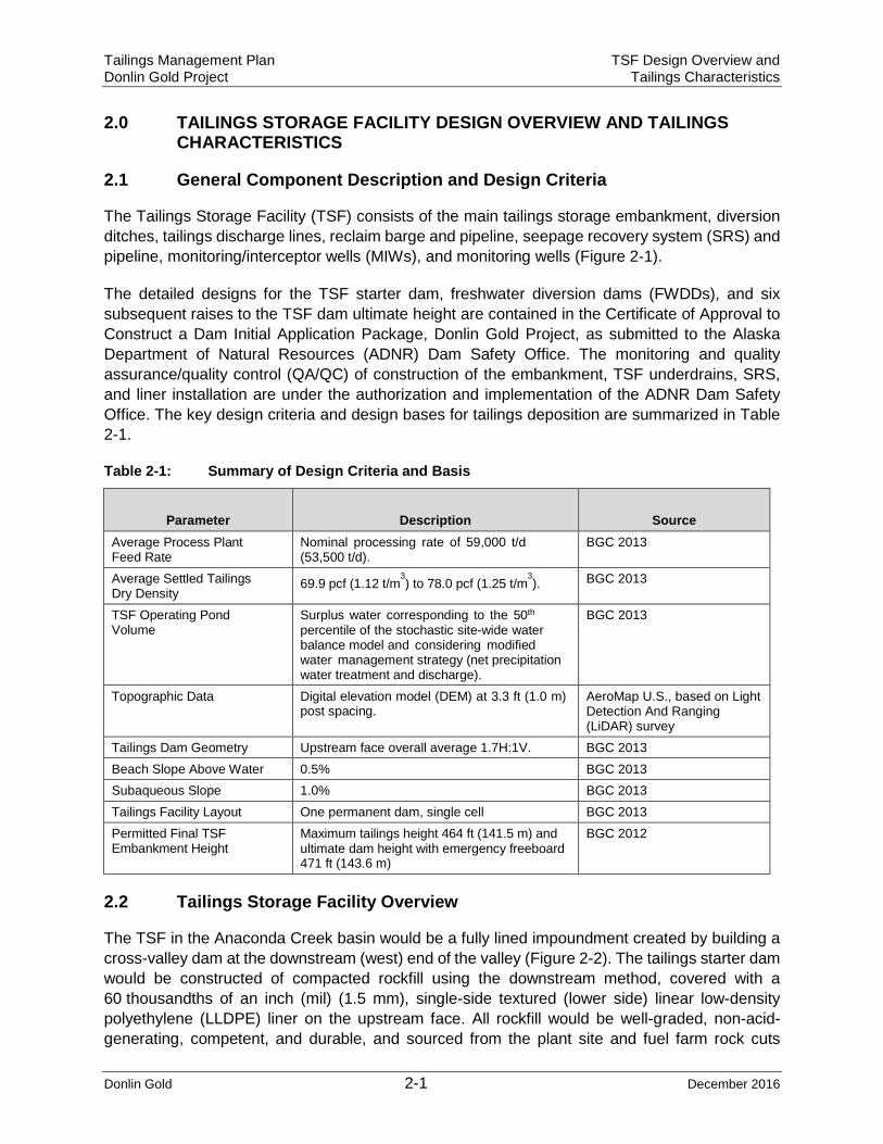
2.1 General Component Description and Design Criteria
The Tailings Storage Facility (TSF) consists of the main tailings storage embankment, diversion ditches, tailings discharge lines, reclaim barge and pipeline, seepage recovery system (SRS) and pipeline, monitoring/interceptor wells (MIWs), and monitoring wells (Figure 2-1).
The detailed designs for the TSF starter dam, freshwater diversion dams (FWDDs), and six subsequent raises to the TSF dam ultimate height are contained in the Certificate of Approval to Construct a Dam Initial Application Package, Donlin Gold Project, as submitted to the Alaska Department of Natural Resources (ADNR) Dam Safety Office. The monitoring and quality assurance/quality control (QA/QC) of construction of the embankment, TSF underdrains, SRS, and liner installation are under the authorization and implementation of the ADNR Dam Safety Office. The key design criteria and design bases for tailings deposition are summarized in Table 2-1.
Table 2-1: Summary of Design Criteria and Basis
Parameter Description Source Average Process Plant Feed Rate
Nominal processing rate of 59,000 t/d (53,500 t/d).
BGC 2013
Average Settled Tailings Dry Density 69.9 pcf (1.12 t/m
3) to 78.0 pcf (1.25 t/m
3). BGC 2013
TSF Operating Pond Volume
Surplus water corresponding to the 50th percentile of the stochastic site-wide water balance model and considering modified water management strategy (net precipitation water treatment and discharge).
BGC 2013
Topographic Data Digital elevation model (DEM) at 3.3 ft (1.0 m) post spacing.
AeroMap U.S., based on Light Detection And Ranging (LiDAR) survey
Tailings Dam Geometry Upstream face overall average 1.7H:1V. BGC 2013 Beach Slope Above Water 0.5% BGC 2013 Subaqueous Slope 1.0% BGC 2013 Tailings Facility Layout One permanent dam, single cell BGC 2013 Permitted Final TSF Embankment Height
Maximum tailings height 464 ft (141.5 m) and ultimate dam height with emergency freeboard 471 ft (143.6 m)
BGC 2012
2.2 Tailings Storage Facility Overview
The TSF in the Anaconda Creek basin would be a fully lined impoundment created by building a cross-valley dam at the downstream (west) end of the valley (Figure 2-2). The tailings starter dam would be constructed of compacted rockfill using the downstream method, covered with a 60 thousandths of an inch (mil) (1.5 mm), single-side textured (lower side) linear low-density polyethylene (LLDPE) liner on the upstream face. All rockfill would be well-graded, non-acid-generating, competent, and durable, and sourced from the plant site and fuel farm rock cuts

Tailings Management Plan TSF Design Overview and Donlin Gold Project Tailings Characteristics
Donlin Gold 2-2 December 2016
(Figure 2-3). The footprint of the impoundment would be lined with a 60 mil (1.5 mm), single-sided textured (textured side down) LLDPE liner over a 3.3 ft (1 m) thick layer of broadly graded silty sand and gravel, which would serve as bedding material to protect the liner from being punctured by sharp overburden particles.
Dams include the starter tailings dam and the North and South FWDDs. The starter dam is designed to store one year of tailings production plus the operating pond, flood and freeboard, and would be 177 ft (54.0 m) high. The North and South FWDDs would be 73.8 ft (22.5 m) and 65.6 ft (20 m) high, respectively. The ultimate height of the tailings dam, as measured from the crest to the downstream toe, would be 471 ft (143.5 m) to store the life-of-mine tailings plus operating pond, flood and freeboard (Figure 2-2). The TSF would have an ultimate capacity of 568 Mst (515 Mt) of tailings, corresponding to an ultimate impoundment surface area of 2,351 acres (951 ha), and would have a total catchment area of 3,755 acres (1,520 ha).
The FWDDs would be maintained at the upstream (east) end of the valley during the first three years of operations to divert fresh water from the impoundment to facilitate liner placement during construction and minimize runoff to the TSF during initial operations. Both the North and South FWDDs have been sized to store the 100-year return period snowmelt runoff and pass the 100-year peak instantaneous flow through their spillways.
The TSF would be constructed in six stages over the mine life using NAG material from the mine after completion of the start dam. Organics and some growth media would be stripped prior to dam and liner construction. The material would be stockpiled in the lower portions of the Anaconda drainage below the TSF footprint.
The TSF would be designed to handle a combination of the 200-year return period snowmelt, 24-hour probable maximum precipitation rainfall event, excess water accumulation under average conditions in the site water balance, and emergency freeboard.
Runoff to the TSF from sideslopes and upper Anaconda Creek would be minimized by staged diversion channels constructed on either side of the facility and the two temporary upstream FWDDs. The SRS would be constructed consisting of the rock underdrain below the lined TSF and diversion ditches at the base of the tailings dam, and collection pond immediately downstream of the tailings dam that would receive water from these sources. There would also be a line of four monitoring/seepage collection wells downstream of the pond.
The seepage water would be either pumped from the collection pond to the process plant during operations or treated and discharged via the APDES permit. During closure and post-closure periods, the seepage collection pond would be used to monitor seepage quality from the TSF. It would initially be pumped from the SRS pond to the ACMA pit. Active pumping of water from the collection pond to the pit would be discontinued when it can be demonstrated that the water quality meets water quality standards.
Groundwater quality downstream of the dam would be monitored at the monitoring/seepage collection wells. If a process water signature is seen in water in these wells, water from the wells would be pumped to the SRS collection pond until water quality returns to baseline levels.

TAILINGS MANAGEMENT PLANOPERATIONS - GENERAL
ARRANGEMENT
FIGURE:SCALE:
DG: PER0543.mxd, 10/05/16, R03
DONLIN GOLD PROJECT
2-1
Grouse Creek
Crevice Creek
Dome
Cree
k
American Creek
Anaconda Creek
C rookedC
reek
Snow Gulch
Queen Gulch
Lewis Gulch
Eagle Creek
Omega Gulch
0 0.5 10.25 mi
0 0.5 10.25 km
Seward Meridian, UTM Zone 4, NAD83K
Operation Details
*̧ Seepage Monitoring Well*̧ Monitoring/Inception Well!. Water Supply Well$+ Water Treatment Plant
LaydownStockpileTSF DiversionRoadBermBuildingClosure DamClosure Tailings CoverDamFacilityGrowth Media StockpileLaydownMaterial SiteOre StockpileOverburden StockpilePitPondRampTSF Reclaim BargeWaste Rock Facility

TSF IMPOUNDMENTFIGURE:SCALE:K
DG: PER0544.mxd, 10/05/16, R02
DONLIN GOLD PROJECT2-2NA
Seward Meridian, UTM Zone 4, NAD83

Tailings Management Plan TSF Design Overview and Donlin Gold Project Tailings Characteristics
Donlin Gold 2-5 December 2016
2.3 Tailings Characteristics
The tailings slurry (approximately 36% solids by weight [solids weight/total weight]) comprised of an approximate mix of 85% floatation tails and 15% CIL tailings would be transported hydraulically to the TSF for sub-aerial deposition. Tailings beach slopes of 0.5% above the water surface and 1% below the operating pond water surface have been assumed for the TSF.
Pilot plant tailings samples were subject to basic index, settling, segregation, large strain consolidation, and falling-head permeability testing (BGC 2011a). The blended tailings sample, prepared at 37% solids content by weight, represents the base case grind. The final blended tailings are classified as low plastic silt, typically consisting of 5% sand, 80% silt, and 15% clay (grain size boundaries as defined in Canadian Geotechnical Society 2006), and have an average specific gravity of 2.72.
Time-dependent consolidation modeling of the TSF was undertaken using the proposed tailings production plant feed and volume-elevation relationship developed for the TSF until steady-state consolidation was reached. The average tailings density is expected to range from 69.9 pcf (1.12 t/m3) at the end of the first year of operations to 78.0 pcf (1.25 t/m3) at the end of the mine life (BGC 2015a).

ULTIMATE TSF DAMFIGURE:
DG: PER0545.mxd, 04/19/16, R00
DONLIN GOLD PROJECT2-3
Seward Meridian, UTM Zone 4, NAD83

Tailings Management Plan TSF Design Overview and Donlin Gold Project Tailings Characteristics
Donlin Gold 2-7 December 2016
2.3.1 Tailings Geochemical Characteristics
Tailings are classified in the uncertain range for potential acid rock drainage (ARD) as a result of neutralization potential/acid generating potential ratios (NP/AP) from test work of between 1 and 2. Acid potential is due to oxidation of sulfides and hydrolysis of ferric iron into jarosite, but due tothe low reactive sulfur content and NP/AP classification, actual potential for ARD is considered to be low (SRK 2011).
2.3.2 Disposal of Domestic Wastewater in the TSF
Two sanitary treatment plant (STP) systems would treat domestic sanitary waste, one at the permanent camp site and one at the process plant site. Treated effluent would be pumped into the TSF after TSF construction is complete in the fourth quarter of Year -1. Solids from the STP systems would be incinerated.

Tailings Management Plan Donlin Gold Project Tailings Management
Donlin Gold 3-1 December 2016
3.0 TAILINGS MANAGEMENT
The overall tailings management plan objectives include:
1. Achieve an approximate ratio of 36% solids to 64% liquids by weight in the tailingsslurry being deposited into the impoundment.
2. Multiple subaerial spigotting deposition locations would form embankment and “force” thesupernatant pool, via selected or cyclical point deposition, to initially flow towards reclaimcollection (i.e. decant) barge located in the center on the north side of the impoundment,and ultimately towards the south east end of the impoundment at the end of processoperations. Note: supernatant solution is entrained slurry water that is forced to thetailings beach surface via consolidation of the beached layer through gravity, as well asprecipitation runoff.
3. Removal of clarified supernatant water from the impoundment surface to the processplant, via operation of the reclaim barge. This is required to maintain the supernatant poolarea at a target of less than 1/3 of the tailings surface area. The centralized pond isintended to allow significant clarification of suspended solids.
4. Minimization of supernatant water in the TSF via:
• Reuse in processing
• Treatment and discharge of TSF water up to the net precipitation amounts allowedthrough the APDES permitting process
• Evaporation of supernatant water during the summer months with air blastevaporators, to prepare for storage of runoff accumulated during the springsnowmelt and summer rains.
The above methods would advance consolidation of tailings solids as the project moves toward final closure and reclamation.
5. Operation of the SRS and potentially pumping from the MIWs to maintain containmentof TSF water and to provide additional process plant make up water.
6. Implement actions that protect exposed liner areas from ice and minimize operationalhazards such as reclaim barge movements that could damage the liner.
7. Minimize spills and leaks into tailings and reclaim pipeline HDPE lined corridors thatprovide secondary containment.
8. Zero spills outside of secondary containment.
3.1 Tailings Deposition
Procedures and objectives for tailings deposition include the following:
• Continuous spigotting off of the tailings dam (spigots spaced every 330 ft (100 m)along the upstream face of the dam) would be required to maintain a tailings beachagainst the tailings dam throughout mine operations.
• Discrete tailings discharge points at various locations from year to year on the eastside of the TSF.

Tailings Management Plan Donlin Gold Project Tailings Management
Donlin Gold 3-2 December 2016
• The operating pond would be maintained a minimum distance of 650 ft (200 m)from the upstream face of the tailings dam.
• The tailings deposition would be managed such that the lowest point in the tailingssurface is located near the center of the TSF, where a reclaim barge can belocated (Figure 3-1) from Year 1 through Year 21.
• To facilitate closure, from Year 22 until t h e end of mine operations (Year 27),the tailings would be deposited in such a way to progressively re-shape the tailingssurface such that the low point of the tailings surface is moved from the centerof the TSF to the southeast corner of the TSF, closer to the closure spillway.(Figure 3-2).
• Based on the modeled tailings deposition results (BGC 2013 and 2015a) and the50th percentile site-wide water balance, the operating pond water is predicted tocome in contact with exposed liner over substantial lengths, between 8,080 ft (2.5km) and 34,610 ft (10.6 km). If during operations the exposed liner is found to besusceptible to tears due to ice loading, contingency measures would be adoptedto protect the exposed sections of the lined impoundment (BGC 2015a).

RECLAIM BARGE LOCATIONDURING OPERATIONS
(Year 1 - 21)
FIGURE:
DG: PER0546.mxd, 10/05/16, R01DONLIN GOLD PROJECT
3-1
Seward Meridian, UTM Zone 4, NAD83KSCALE:
NA

TAILINGS DEPOSTION(Year 22 - 27)
FIGURE:
DG: PER0547.mxd, 10/05/16, R01
DONLIN GOLD PROJECT3-2
Seward Meridian, UTM Zone 4, NAD83KSCALE:
NA

Tailings Management Plan Donlin Gold Project Tailings Management
Donlin Gold 3-5 December 2016
3.2 Tailings Pond and Beach
The preferred east and west tailings deposition scenario would result in the anticipated beach and pond areas listed by year in Table 3-1. The actual pond and beach areas would vary depending on precipitation and amount of supernatant water sent to the process plant or water treatment plant (Figure 3-3).
Table 3-1: TSF Pond and Beach Areas
End of Year East and West Discharge
Beach Area Pond Area (acres) (hectares) (acres) (hectares)
1 111 45 192 78 5 425 172 430 174 9 719 291 503 204 13 934 378 581 235 17 1,107 448 654 265 21 1,192 482 780 316 25 1,333 539 808 327 27 1,502 608 740 299
BGC 2015a
Figure 3-3: Typical Beach and Pond Configuration
BGC 2015a
Fugitive Dust Control
Wind erosion may generate fugitive dust emissions from the exposed TSF beaches during extended periods of low precipitation. Management of the subaerial spigotting of the tailings would keep the beach surfaces wet or damp to minimize fugitive dust (BGC 2015a). In areas where it is not practical to maintain a wet beach an air blast evaporation system would serve a dual purpose: first, to enhance evaporation of supernatant water as

Tailings Management Plan Donlin Gold Project Tailings Management
Donlin Gold 3-6 December 2016
part of the water management system and second, to maintain a wet or moist cover of the exposed beaches (Figure 3-4). Water applications (i.e., sprinklers) may also be used as a control measure to minimize fugitive dust emissions (Air Sciences 2015).
The air blast evaporator system would spray water into the atmosphere to enhance evaporation. Approximately 23 evaporation units would be deployed around the TSF with potential annual evaporation volume of 350 acre-ft (0.43 Mm3) or 216 gpm (49 m3/h). These units may be operated when the TSF pond volume exceeds 6,490 acre-ft (8.0 Mm3) or during dry periods when there is potential for material on the TSF beaches to generate wind-borne dust (BGC 2015b).
Figure 3-4: Air Blast Evaporators Deployed at Site - August 2013
Figure 3-5: Typical Tailings Facility Air Blast Evaporators

Tailings Management Plan Donlin Gold Project Tailings Management
Donlin Gold 3-7 December 2016
TSF Ice Formation
Given the sub-arctic climate at the project site, ice is expected to form on the operating pond during the winter months. In contrast, ice is not expected to form on the tailings beach due to the high temperature of the tailings when discharged. An unfavorable situation could potentially develop if the operating pond inundates the entire tailings beach during operations. This scenario would place the pond in direct contact with the liner, leading to the potential for liner damage due to ice-loading. Damage could result from either horizontal ice movement due to wind loading or thermal expansion, or vertical ice loads due to rising or lowering pond levels during the winter. To address this risk, the TSF would be operated such that the beach above water has a slope of 0.5%, and the beach below water (subaqueous) has a slope of 1.0% (BGC 2013). By keeping TSF water within the inner cone, ice loading issues would be mitigated.
3.3 TSF Inspections
This section outlines the O&M procedures and corresponding monitoring requirements for the TSF. The monitoring program would include both informal routine inspections by operations personnel and formal inspection monitoring for the ultimate operation of the TSF. Table 3-2 lists the TSF Inspection Schedule.
Tailings Management Plan Donlin Gold Project Tailings Management
Donlin Gold 3-8 December 2016
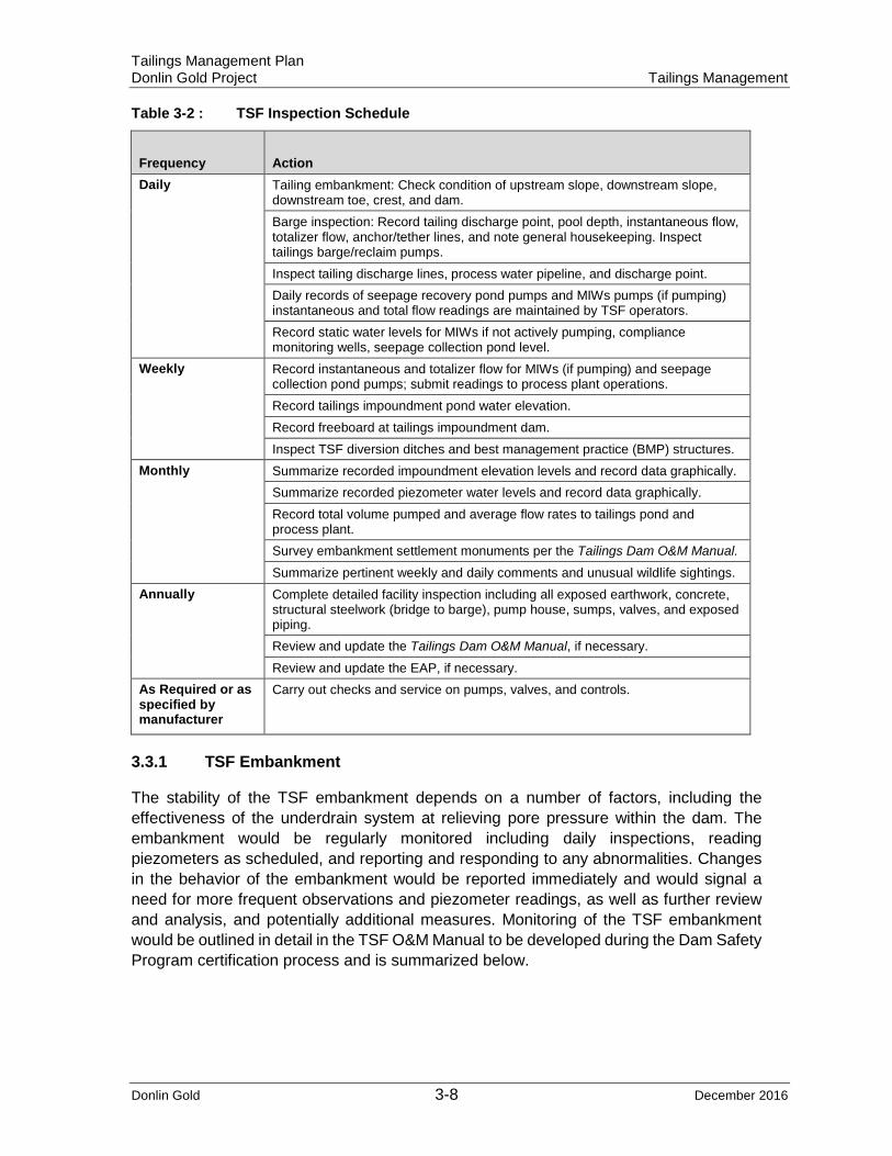
Table 3-2 : TSF Inspection Schedule
Frequency Action Daily Tailing embankment: Check condition of upstream slope, downstream slope,
downstream toe, crest, and dam. Barge inspection: Record tailing discharge point, pool depth, instantaneous flow, totalizer flow, anchor/tether lines, and note general housekeeping. Inspect tailings barge/reclaim pumps. Inspect tailing discharge lines, process water pipeline, and discharge point. Daily records of seepage recovery pond pumps and MIWs pumps (if pumping) instantaneous and total flow readings are maintained by TSF operators. Record static water levels for MIWs if not actively pumping, compliance monitoring wells, seepage collection pond level.
Weekly Record instantaneous and totalizer flow for MIWs (if pumping) and seepage collection pond pumps; submit readings to process plant operations. Record tailings impoundment pond water elevation. Record freeboard at tailings impoundment dam. Inspect TSF diversion ditches and best management practice (BMP) structures.
Monthly Summarize recorded impoundment elevation levels and record data graphically. Summarize recorded piezometer water levels and record data graphically. Record total volume pumped and average flow rates to tailings pond and process plant. Survey embankment settlement monuments per the Tailings Dam O&M Manual.
Summarize pertinent weekly and daily comments and unusual wildlife sightings. Annually Complete detailed facility inspection including all exposed earthwork, concrete,
structural steelwork (bridge to barge), pump house, sumps, valves, and exposed piping. Review and update the Tailings Dam O&M Manual, if necessary.
Review and update the EAP, if necessary. As Required or as specified by manufacturer
Carry out checks and service on pumps, valves, and controls.
3.3.1 TSF Embankment
The stability of the TSF embankment depends on a number of factors, including the effectiveness of the underdrain system at relieving pore pressure within the dam. The embankment would be regularly monitored including daily inspections, reading piezometers as scheduled, and reporting and responding to any abnormalities. Changes in the behavior of the embankment would be reported immediately and would signal a need for more frequent observations and piezometer readings, as well as further review and analysis, and potentially additional measures. Monitoring of the TSF embankment would be outlined in detail in the TSF O&M Manual to be developed during the Dam Safety Program certification process and is summarized below.

Tailings Management Plan Donlin Gold Project Tailings Management
Donlin Gold 3-9 December 2016
Inspections and Monitoring - Embankment
Daily inspections of the embankment would include observations for settlements, heaving, deflections, and lateral movement, as well as increased or decreased seepage, new seepage areas, or erosion. Inspections are conducted along the exposed abutment contacts, upstream and downstream faces of the dam, crest, and the toe of the dam. These observations and measurements would be reported on the daily inspection form shown in the Appendix A: TSF Daily and Weekly Inspection Forms (to be developed).
Monitoring would record the impoundment elevation, seepage collection pond sump water elevation, and piezometer readings (including the temperature at each piezometer). Observations would be recorded digitally or on the form shown in Appendix B: Piezometer Monitoring Forms (to be developed). After data reduction, water levels would be graphically displayed on a summary graph.
The piezometers would be read weekly when material is being placed in the embankment and monthly otherwise. Piezometer readings would be recorded on the specific form in Appendix B. Raises of the tailing embankment would be inspected during construction by the design-engineering firm. A construction inspection report would be issued at the completion of each raise and would be submitted to the State of Alaska, Division of Mining and Water Management, Dam Safety Section.
3.3.2 Tailings Discharge Pipeline
The tailings pipeline would be surface-run and installed in a 52.5 ft (16 m) wide pipeline service corridor together with the reclaim water and other utility pipelines. The pipeline corridor would be high density polyethylene (HDPE)-lined from the process plant to the tailings impoundment to direct any leaks or minor spills to the tailings impoundment. The tailings pipeline would not be insulated, allowing direct observation of the pipe. Monitoring of the tailings pipeline is summarized below.
Inspection and Monitoring - Tailings Discharge Lines
The tailings discharge line would be inspected daily for leaks, erosion, and settlement. Leaks are most likely to occur at saddle off-takes, valves, fabricated bends, drop boxes, and along steep downgrades. Daily visual inspections would focus on these areas. TSF operators would perform operations, maintenance, inspections, and record keeping on a daily basis unless otherwise specified.
Visual inspection of the discharge point into the tailings impoundment would occur daily. Items checked include excessive movement or vibration of the HDPE pipe, excessive erosion, reduction or loss of flow, etc.
The tailings discharge point would be noted on the daily inspection form (Appendix A). The daily shift log would provide a record of the tons of tailings discharged, percent solids in the tailings discharged, and the duration of any shutdowns.
All tailing pipelines would be inspected annually for i n te rna l abrasion wear and replaced as necessary. The observations of the tailings discharge line condition would

Tailings Management Plan Donlin Gold Project Tailings Management
Donlin Gold 3-10 December 2016
be recorded on the “TSF Annual Inspection Form” as shown in Appendix C (to be developed).
Periodic inspections of sub-aerial deposition would be performed as appropriate to determine if the desired depositional patterns are being achieved. Sub-aerial deposition would be inspected visually. Additionally, a bathymetric survey to measure the deposition using a depth sounder would be done twice a year, in the spring and fall.
3.3.3 Reclaim Water System
Reclaim water from the tailings pond would be pumped from a pump barge through a pipeline back to the process plant. The reclaim water barge would have three vertical turbine pumps (two operating, one standby). The barge would be anchored along the north side of the TSF and accessed via a walkway/pipe support bridge.
The reclaim pipeline would be surface-run for approximately 1.5 miles (2.4 km), pre-insulated with 3 inches (76 mm) of polyurethane, and installed in the same pipeline services corridor as the tailings and other utility pipelines.
Inspection and Monitoring – Reclaim Water System
The barge and reclaim water pipeline would be inspected daily for any unusual noises from the pumps, excessive snow loads on the barge, etc. Other critical items include indications or signs of leaks or excessive movement, particularly at the connection between the barge and the shore. If any adverse conditions are observed, appropriate corrective action would be taken.
Observations and measurements, such as the depth of water under the barge, pontoon condition, deicing system performance, condition of the valves, total barge pump time, instantaneous flows for each pump, and monthly totalizer flow, would be recorded on the “Barge Inspection Form - Daily” (Appendix A) .
An annual inspection (Appendix C) of the barge would be conducted to look for signs of corrosion, grounding problems, and general wear and tear. Fire extinguishers, life preservers, and other safety equipment would be inspected regularly and serviced or replaced as required.
3.3.4 TSF Seepage Recovery System
The SRS would be installed as part of the lined TSF dam (BGC 2011a). The SRS located at the toe of the TSF would collect surface water from the unlined downstream dam face, near surface groundwater from the TSF rock underdrain, and potential seepage through the TSF liner that enters the TSF rock underdrains. The SRS water would be sent directly to the process plant as part of the process freshwater requirement or pumped to the Water Treatment Plant (WTP) for treatment and discharge.
The SRS would incorporate a collection pond, Monitoring/Interception wells (MIWs), and compliance monitoring wells. The MIWs would be installed downstream of the collection pond, and would include two wells drilled to 165 ft (50 m) depth and two wells drilled to
Tailings Management Plan Donlin Gold Project Tailings Management
Donlin Gold 3-11 December 2016
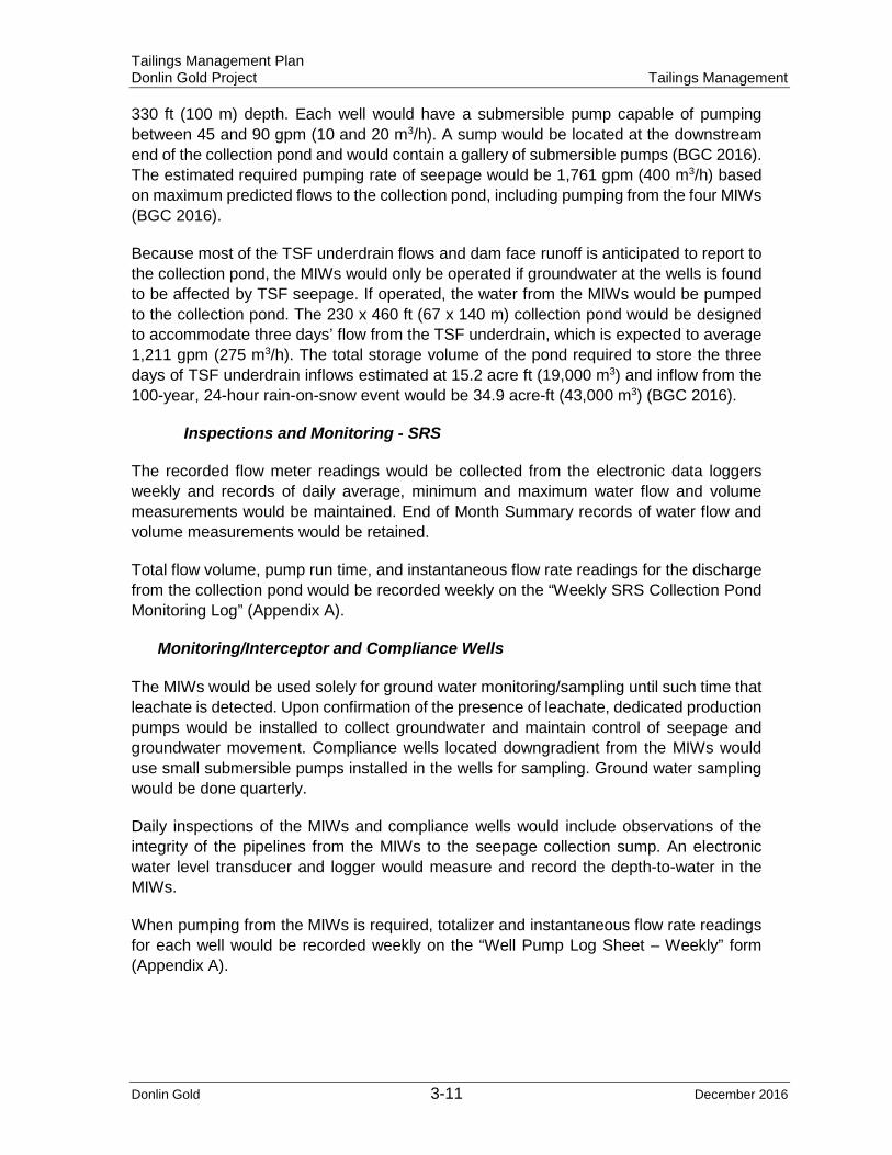
330 ft (100 m) depth. Each well would have a submersible pump capable of pumping between 45 and 90 gpm (10 and 20 m3/h). A sump would be located at the downstream end of the collection pond and would contain a gallery of submersible pumps (BGC 2016). The estimated required pumping rate of seepage would be 1,761 gpm (400 m3/h) based on maximum predicted flows to the collection pond, including pumping from the four MIWs (BGC 2016).
Because most of the TSF underdrain flows and dam face runoff is anticipated to report to the collection pond, the MIWs would only be operated if groundwater at the wells is found to be affected by TSF seepage. If operated, the water from the MIWs would be pumped to the collection pond. The 230 x 460 ft (67 x 140 m) collection pond would be designed to accommodate three days’ flow from the TSF underdrain, which is expected to average 1,211 gpm (275 m3/h). The total storage volume of the pond required to store the three days of TSF underdrain inflows estimated at 15.2 acre ft (19,000 m3) and inflow from the 100-year, 24-hour rain-on-snow event would be 34.9 acre-ft (43,000 m3) (BGC 2016).
Inspections and Monitoring - SRS
The recorded flow meter readings would be collected from the electronic data loggers weekly and records of daily average, minimum and maximum water flow and volume measurements would be maintained. End of Month Summary records of water flow and volume measurements would be retained.
Total flow volume, pump run time, and instantaneous flow rate readings for the discharge from the collection pond would be recorded weekly on the “Weekly SRS Collection Pond Monitoring Log” (Appendix A).
Monitoring/Interceptor and Compliance Wells
The MIWs would be used solely for ground water monitoring/sampling until such time that leachate is detected. Upon confirmation of the presence of leachate, dedicated production pumps would be installed to collect groundwater and maintain control of seepage and groundwater movement. Compliance wells located downgradient from the MIWs would use small submersible pumps installed in the wells for sampling. Ground water sampling would be done quarterly.
Daily inspections of the MIWs and compliance wells would include observations of the integrity of the pipelines from the MIWs to the seepage collection sump. An electronic water level transducer and logger would measure and record the depth-to-water in the MIWs.
When pumping from the MIWs is required, totalizer and instantaneous flow rate readings for each well would be recorded weekly on the “Well Pump Log Sheet – Weekly” form (Appendix A).
Tailings Management Plan Donlin Gold Project Tailings Management
Donlin Gold 3-12 December 2016
3.3.5 Temporary Reservoirs (Freshwater Diversion Dams) – Tailings Storage Facility
The storm water reservoirs would play a role during construction of the main TSF impoundment to temporarily store and divert water from the impoundment construction area for the first three years of construction. Storm water impounded in the temporary North and South FWDD reservoirs would be pumped to diversion ditches and flow to Anaconda Creek below the main TSF dam.
3.3.6 TSF Diversions
Three stages of channel diversions are currently proposed for the TSF to limit runoff from undisturbed ground (Figure 2-1). The channel diversions would be constructed on the north and south slopes of the TSF and would divert runoff from areas ranging in size for the north diversions from 618 to 939 acres (250 to 380 ha), and the south diversions from 148 to 395 acres (60 to 160 ha).
The diversion channels would be lined with 40 mil (1 mm) LLDPE and have an expected efficiency of 90%. All channels would be constructed at an approximate gradient of 0.5%. The diversion channels would require excavations to accommodate 200-year return period peak flows of 32 to 131 cfs (0.9 to 3.7 m3/s) (BGC 2011b).
Inspections and Monitoring – Diversions
Weekly inspections of diversion ditches would be the routine procedure and additional inspections would occur immediately after a significant storm event. The inspection and monitoring for the diversions would be specific to the site-wide Storm Water Pollution Prevention Plan (SWPPP) for the proposed Donlin Gold project (to be developed).
3.4 Water Quality and Solids Monitoring
The site-wide Integrated Waste Management Monitoring Plan (SRK 2016a) provides a comprehensive summary of all tailings solutions and solids that will be monitored under the fluid management system and includes the following:
• Tailings in the process plant after cyanide detoxification
• Tailings liquor (filtrate) and solids (residue) from the tailings discharge box at theprocess plant
• Tailings decant solution from the impoundment (typically sampled at the reclaimbarge)
• The SRS collection pond water
• MIWs downgradient of the SRS pond. If seepage is found to be bypassing the TSFSRS, these would be pumped to recover impacted groundwater
• Compliance monitoring wells located downgradient of the MIWs.

Tailings Management Plan Donlin Gold Project Tailings Management
Donlin Gold 3-13 December 2016
3.5 Storm Water Management
Surface discharges to diversion ditches and local drainages during operations would have a potential to result in increased erosion and sedimentation. However, BMPs detailing sediment and erosion control measures would be developed and implemented as part of the SWPPP. Inspection and monitoring requirements under Alaska Pollutant Discharge Elimination System (APDES) Multi-Sector General permit (MSGP) and Integrated Waste Management Monitoring Plan have some redundancy related to the operation of the TSF and ancillary facilities, but both plans would be implemented by the Environmental Department and TSF Operations.

Tailings Management Plan Donlin Gold Project References
Donlin Gold 4-1 December 2016
4.0 REFERENCES Air Sciences. 2015. Fugitive Dust Control Plan, Donlin Gold Project.
BGC Engineering. 2011a. Tailing Storage Facility Design Final Report, Document Number DC11-025. July 22, 2011.
BGC Engineering. 2011b. Water Management Plan Final Report, Document Number DC11-032. July 22, 2011.
BGC Engineering. 2012. Certificate of Approval to Construct a Dam: Initial Application Package, Donlin Gold Project, BGC Document Number ER-0011129.0004. December (Submitted to ADNR as part of initial application package on April 12).
BGC Engineering. 2013. Donlin Gold Project Tailings Storage Facility, Conceptual Tailings Deposition Plan, Reference Number PM-0011147.0003. July 19.
BGC Engineering. 2015a. Tailings Beach Areas for Advanced Water Treatment Alternative, Reference Number PM-0011186.0067. May 27.
BGC Engineering. 2015b. Water Resources Management Plan: Advanced Water Treatment – Rev 1, Reference Number PM-0011186.0064. September 10.
BGC Engineering. 2016. Donlin Gold Tailings Storage Facility Freshwater Diversion and Seepage Recovery System, Design Memorandum. Reference Number ED-0011186.0083. April 19.
Canadian Geotechnical Society. 2006. Canadian Foundation Engineering Manual, Fourth Edition, 488 pg.
SRK Consulting. 2011. Metal Leaching and Acid Rock Drainage Assessment, Donlin Creek Project, updated report.
SRK Consulting. 2016a. Integrated Waste Management Plan, Volume III, Donlin Gold Project.
SRK Consulting. 2016b. Reclamation and Closure Plan, Volume IV, Donlin Gold Project.
SRK Consulting. 2016c. Water Resources Management Plan, Volume II, Donlin Gold Project.
SRK Consulting. 2016d. Project Description, Volume I, Donlin Gold Project.
SRK Consulting, 2016e. Waste Rock Management Plan, Volume IIIB, Donlin Gold Project.

Appendix A TSF Daily and Weekly Inspection Forms
(to be developed)

Appendix B Piezometer Monitoring Forms
(to be developed)

Appendix C TSF Annual Inspection Forms
(to be developed)