Embed Size (px)
Citation preview

DoDEA FACILITIES MANAGEMENT GUIDE:
TECHNOLOGY SYSTEMS DESIGN GUIDELINES DODEA SPECIAL SYSTEMS VERSION 2.0
DEPARTMENT OF DEFENSE EDUCATION ACTIVITY
February 11, 2016 PRE FINAL DRAFT
DoDEA Technology Systems Design Guide DoDEA Special Systems Requirements
Version2.0(Pre‐finalDraft)–February11,2016 Page1
TABLE OF CONTENTS
Acronyms ........................................................................................................................................ 4
1.0 Purpose ........................................................................................................................ 7
2.0 Applicability ................................................................................................................. 7
3.0 References ................................................................................................................... 8
4.0 Responsibilities ............................................................................................................ 9
5.0 Designer/Construction Contractor Requirements ...................................................... 10
6.0 Access Control ............................................................................................................ 12
6.1. Proximity Card Reader System ......................................................................................... 12
6.2. Access‐Intercom/Video Phone (AI Phone) ....................................................................... 13
6.3. Automated Access Gate Controls ..................................................................................... 13
6.4. Intrusion Detection and CCTV ........................................................................................... 13
6.5. Duress Button ................................................................................................................... 13
6.6. Door Buzz‐in ...................................................................................................................... 13
6.7. ADA Access ........................................................................................................................ 13
6.8. Mass Notification System (MNS) ...................................................................................... 13
7.0 CATV Systems (Cable TV) ............................................................................................ 14
8.0 A/V Systems ............................................................................................................... 14
8.1 Learning Space Voice Enhancement ................................................................................. 14
8.2 Smart Board or Interactive Whiteboard ‐ IWB ................................................................. 14
8.3 Video Projection and Projector ......................................................................................... 15
8.4 Distance Learning .............................................................................................................. 16
8.5 Video Production (Broadcast Room) ................................................................................ 16
8.6 COW or SmartCart ............................................................................................................ 16
9.0 IPTV ........................................................................................................................... 16
9.1 Internet Protocol Television ‐ IPTV ................................................................................... 16
DoDEA Technology Systems Design Guide DoDEA Special Systems Requirements
Version2.0(Pre‐finalDraft)–February11,2016 Page2
10.0 Telephone Systems .................................................................................................... 17
10.1 Service Coordination ......................................................................................................... 17
10.2 Phone Lines ....................................................................................................................... 17
10.3 Phone Locations ................................................................................................................ 18
10.4 911 Service ........................................................................................................................ 18
11.0 Intercom/Clock/PA/Bell System ................................................................................. 19
11.1 General .............................................................................................................................. 19
11.2 Clock Synchronization ....................................................................................................... 19
11.3 Intercom ............................................................................................................................ 20
11.4 PA System ......................................................................................................................... 20
12.0 Automated Parent Notification System ...................................................................... 21
13.0 Building Automation Systems .................................................................................... 21
13.1 Required Functions ........................................................................................................... 21
13.2 Communications ............................................................................................................... 25
13.3 Thermostats ...................................................................................................................... 25
14.0 Sports Fields Fiber Optic Cable ........................................................................................ 25
15.0 Monitors and Displays ................................................................................................ 26
15.1 Interior Message Displays ................................................................................................. 26
15.2 Energy Dashboards ........................................................................................................... 26
15.3 Exterior Electronic Marquees ........................................................................................... 27
16.0 Stage/Platform/Special Space Requirements ............................................................. 28
16.1 Lighting Control ................................................................................................................. 28
16.2 A/V Control Integration Stations ...................................................................................... 29

DoDEA Technology Systems Design Guide DoDEA Special Systems Requirements
Version2.0(Pre‐finalDraft)–February11,2016 Page3
16.3 Sound Systems .................................................................................................................. 29
16.4 IT Support .......................................................................................................................... 30
16.5 Rigging and Drapery .......................................................................................................... 30
17.0 Designer Checklist ...................................................................................................... 32
Appendix 1 IWB Dimensions .............................................................................................. 33
Appendix 2 IT Connection Matrix ...................................................................................... 35
Appendix 3 Sample Neighborhood – IT layout ................................................................... 39
Appendix 4 IT Submission Checklist ................................................................................... 40
Appendix 5 Sample Clock Layout Diagram ......................................................................... 41
Appendix 6 BAS System QC Checklist ................................................................................. 42
System Oversight Responsibilities
System HQ DoDEA Lead E‐Mail Phone #
Designer Requirements HQ Facilities [email protected] 571‐372‐1342
Access Controls HQ Safety/Security See Section 6.0 See Section 6.0
CATV & IPTV HQ IT ASA [email protected] 571‐372‐1465
Audio‐Visual Systems HQ Education [email protected] 571‐372‐5841
Telephone (VOIP & Analog) HQ IT ASA [email protected] 571‐372‐1465
PA/Intercom/Clocks/Bells HQ Education [email protected] 571‐372‐5841
Building Automation System HQ Facilities [email protected] 571‐372‐1342
Monitors & Displays HQ Education [email protected] 571‐372‐5841
Stage (sound, lighting, AV, rigging) HQ Education [email protected] 571‐372‐5841
Broadcast Room HQ Education [email protected] 571‐372‐5841

DoDEA Technology Systems Design Guide DoDEA Special Systems Requirements
Version2.0(Pre‐finalDraft)–February11,2016 Page4
ACRONYMS
ADA Americans with Disabilities Act
A/E Architect/Engineer
AFCEC Air Force Civil Engineer Center
AGC Application Generic Controllers
AI Access Intercom
ASA Architecture, Standards and Auditing
ASC Application Specific Controllers
AV/A/V Analog Video/Audio‐Visual
BAS Building Automation System
BICSI Building Industry Consulting Services, International
CAT6 Category 6 UTP Cable
CATV Cable Television
CCTV Closed Circuit Television
CFCI Contractor Furnished Contractor Installed
COW Computers on Wheels
CTE Career Tech Education
BAS Direct Digital Control
DIACAP‐DITSCAP Department of Defense Information Assurance Certification and
Accreditation Process/Defense Information Technology Security
Certification and Accreditation Process
DID Direct Dial Access
DMX Direct Media Exchange
DoDEA Department of Defense Education Activity
DSO District Superintendent’s Office
DVD Digital Video Disc
DVI Digital Video Interface

DoDEA Technology Systems Design Guide DoDEA Special Systems Requirements
Version2.0(Pre‐finalDraft)–February11,2016 Page5
FF&E Furniture, Fixtures and Equipment
GFGI Government Furnished Government Installed
GPS Global Positioning System
HD High Definition
HDMI High Definition Multimedia Interface
HVAC Heating, Ventilation and Air Conditioning
IP Internet Protocol
IPTV Internet Protocol Television
ISBN International Standard Book Number
IT Information Technology
IWB Interactive White Board
LAN Local Area Network
LC Local Call
LCD Liquid Crystal Display
LED Light Emitting Device
LEED Leadership in Energy and Environmental Design
LIMM Learning Impaired Mild Moderate
LIMS Learning Impaired Moderate to Severe
MDF Main Distribution Frame
MILCON Military Construction
MNS Mass Notification System
NAVFAC Naval Facilities Command
OSP Outside Plant Cables
OTPT Occupational Therapy/Physical Therapy
PA Public Address
PBX Private Branch Exchange
PM Project Manager

DoDEA Technology Systems Design Guide DoDEA Special Systems Requirements
Version2.0(Pre‐finalDraft)–February11,2016 Page6
POS Point of Sale
PV Photo Voltaic
QC Quality Control
RF Radio Frequency
SATT School as a Teaching Tool
SC Single Channel
SCPT Standard Defined Configuration Parameter Types
SNVT Standard Network Variable Type
TM Technical Manager
TR Telecommunications Room
UFC Unified Facilities Criteria
USACE United States Army Corps of Engineers
UCPT User Defined Configuration Parameter Types
USB Universal Serial Bus
VGA Video Graphics Accelerator
VOD Video on Demand
VoIP Voice over Internet Protocol

DoDEA Technology Systems Design Guide DoDEA Special Systems Requirements
Version2.0(Pre‐finalDraft)–February11,2016 Page7
1.0 PURPOSE
This design guide has been prepared to provide the Architect/Engineer (A/E) community with the necessary criteria to assist in the design of the special (non‐network) systems that are typically found in an educational facility. While certain features of the system design shall vary from project to project, the requirements reflected in this guide are intended to provide the minimum requirements required by the Department of Defense Education Activity (DoDEA). This document represents the Special Systems portion of the design guide. The DoDEA Network guidelines shall accompany this document and include standards for additional network systems.
2.0 APPLICABILITY
These instructions apply to DoDEA, the US Army Corps of Engineers (USACE) Norfolk DoDEA Design Center, Construction Agents having DoDEA Military Construction (MILCON) responsibilities to include USACE, Naval Facilities Command (NAVFAC), and the Air Force Civil Engineer Center (AFCEC), as well as Architect/Engineer (design) firms, and construction contractors. These instructions are intended to be used for new DoDEA MILCON projects or projects that are modifying existing facilities. For all new or modified DoDEA facilities, the designer/construction contractor must demonstrate that the criteria outlined in this and other relevant guides for each special (non‐network) technology system have been met. Host Nation funded projects should comply with this guideline to the greatest extent possible; after standard warranty periods have expired, any modifications to host nation funded facilities shall comply with the criteria outlined in this guide.

DoDEA Technology Systems Design Guide DoDEA Special Systems Requirements
Version2.0(Pre‐finalDraft)–February11,2016 Page8
3.0 REFERENCES
References include, but are not limited to, the following documents. Use the most recent version available of the listed references, if the listed version has been superceded. NFPA 70, National Electrical Code NFPA 101, Life Safety Code ANSI/IEEE C2‐2007, National Electrical Safety Code UFC 3‐410‐02, Direct Digital Control for HVAC and Other Building Control Systems Unified Facilities Criteria (UFC) 4‐021‐01, Mass Notification Systems

DoDEA Technology Systems Design Guide DoDEA Special Systems Requirements
Version2.0(Pre‐finalDraft)–February11,2016 Page9
4.0 RESPONSIBILITIES
4.1 HEADQUARTERS, DEPARTMENT OF DEFENSE EDUCATION ACTIVITY HQ DoDEA is responsible for program management by providing scope, direction, funding, and financial management of the entire DoDEA Military Construction (MILCON) design and construction program. HQ DoDEA Facilities Branch, in coordination with the DoDEA Design Center, and each DoDEA Area Project Manager (PM), is responsible for ensuring that design submittals for DoDEA projects are routed through HQ DoDEA’s Information Technology (IT) Architecture, Standards and Auditing (ASA) MILCON review team. The HQ IT ASA MILCON review team reviews and provides timely comments on design submittals to ensure compliance with this guide and other relevant standards, and provides review comments to the respective DoDEA Area PM to be implemented into the project. Other HQ DoDEA functions, such as, but not limited to, the Office of Safety and Security or Education Division, shall also provide guidance where their Areas of Responsibility intersect with Special Technology System requirements.
4.2 DODEA AREAS (DODEA‐AMERICAS, EUROPE AND PACIFIC ) The DoDEA Area Offices shall provide a Project Manager (PM) who shall coordinate with the School Superintendent, local logistical staff, and host installation representatives regarding local Special technology requirements. This individual, the Logistics Division Facilities Engineer for the project, shall be referred to throughout this document as the DoDEA Area PM. In concert with the HQ staff, to include the IT ASA MILCON review team, DoDEA Area Facilities and IT representatives, the DoDEA Design Center, and the Construction Agent Project Manager, the DoDEA Area PM shall ensure that the A/E and construction contractor implement the latest DoDEA standards for DoDEA Network and Special systems within DoDEA projects. The DoDEA Area PM shall initiate coordination with IT ASA at the Planning stage of the project, with detailed IT ASA drawing reviews beginning at the 35% stage for all projects.
4.3 HOST INSTALLATION The host installation and supporting agencies (such as the Network Enterprise Center on Army installations) are responsible for working with the DoDEA Area PM to ensure DoDEA projects satisfactorily incorporate local Special technology requirements.
DoDEA Technology Systems Design Guide DoDEA Special Systems Requirements
Version2.0(Pre‐finalDraft)–February11,2016 Page10
4.4 CONSTRUCTION AGENT
The Construction Agent Project Manager for USACE, NAVFAC or AFCEC, in concert with the DoDEA Area Office PM, and the DoDEA Design Center, shall ensure that the A/E and construction contractor implement the latest DoDEA standards for DoDEA Network and Special systems within DoDEA projects.
4.5 DODEA DESIGN CENTER – NORFOLK DISTRICT TECHNICAL MANAGER (TM)
The Norfolk District TM supports HQ DoDEA, the DoDEA Area Office PM, the Construction Agent, and the A/E as a technical subject matter expert. The Norfolk District TM shall support IT design reviews to verify compliance with the latest DoDEA standards for DoDEA Network and Non‐Network systems. Along with the DoDEA Area PM, the Norfolk District TM shall ensure that review comments provided by the IT ASA MILCON review team are adequately addressed in DoDEA project designs.
4.6 ARCHITECT/ENGINEER DESIGNER AND CONSTRUCTION CONTRACTOR
The Architect/Engineer designer and construction contractor must demonstrate that the criteria outlined in this and other relevant guides for each special technology system have been met in all new or modified DoDEA facilities.
In general, telecommunications racks, conduit, cable trays, terminations, and outlets shall be MILCON funded. Rack switches are typically Operations & Maintenance (O&M) funded. Controllers and amplifiers for PA/Intercom/Clocks/Bells, proximity card access controls, Ai‐Phone access controls, etc. can be MILCON or O&M funded depending upon the interpretation of the contracting authority in an individual Area, but, if funds are available, use of MILCON funds for these systems is preferred in order to ensure complete and usable/testable systems at construction completion.
5.0 DESIGNER/CONSTRUCTION CONTRACTOR REQUIREMENTS
5.1 All IT and special systems, both software and hardware, installed, intended to be
procured as FF&E or otherwise used in DoDEA schools must have prior approval and are subject to DITSCAP/DIACAP security provisions. A/E design teams shall contact their DoDEA Area PM at the appropriate time during design to obtain the latest listing of approved systems and software. These items are suggested for use as basis of design, but not required. Items not specifically listed on this pre‐approved listing that are intended for use in a DoDEA school design or used as a basis of design intent should be submitted as a separate, independent package to HQ DoDEA, Attn: Director of Information Technology for review and preliminary ,

DoDEA Technology Systems Design Guide DoDEA Special Systems Requirements
Version2.0(Pre‐finalDraft)–February11,2016 Page11
approval. DoDEA will initiate the approval of these systems if they are deemed appropriate. Software must also be approved as discussed in Section 5.6, below.
5.2 Systems are integrated for operational efficiency, cost, and functionality. The systems
designer shall research and identify existing telecom solutions approved for use on DoDEA and DoD networks. The systems designer shall make recommendations for telecom solutions that do not exist in DoDEA that shall improve operational efficiencies of existing systems.
5.3 The systems designer shall ensure that the project specifications require training on all
systems that will be provided at the actual facility 30 days prior to student occupation. Length of training shall be in accordance with manufacturer’s recommendations, and an operation’s manual and instructional materials specific to each system installed shall be provided. The manuals and instructional materials shall be approved by the end user (DoDEA Area PM) before being finalized. A DVD video of each training session shall also be provided. This training shall include follow‐on assistance by system installers or solution providers for 90 days after the facility is occupied. The user shall be supported telephonically, through web training, and/or onsite if necessary.
5.4 Coordinating through the DoDEA Area PM, the contractor shall provide qualified
personnel at the facility on the first day of actual operation to observe and assist school administration with the systems’ operation. It is the system designer’s responsibility to coordinate through the DoDEA Area PM to identify the DoDEA personnel who shall be trained on each system. Each system identified may have different personnel.
5.5 Non‐DoDEA Network systems like phone (non‐VOIP), BAS, HVAC controls, access
controls, energy dashboard, PA/intercom/clocks/bells, audio‐visual, projection, lighting, and sound systems shall be designed with a stand‐alone cabling system. These systems shall not rely on DoDEA network operability. These Special systems shall be on a single separate “facilities network” with one connection to the DoDEA Network (after software approval). Total building automation integration is desired (one entity to integrate all above systems to ensure they are complete, useable, and fully functional). In some cases, only the primary controller/computer of a non‐network system may be allowed to connect to the DoDEA Network so it can be monitored/controlled remotely and have its software periodically updated. The systems designer shall require the construction contractor to gain approval of any proposed software that will be connected to the DoDEA Network (i.e. BAS, Access Controls, PA/Intercom) and provide a free copy of the software to HQ DoDEA for testing. For planning, software approval will take 120‐days (upon request through the DoDEA PM); DoDEA software approval must be gained prior to connecting any system to the DoDEA Network.

DoDEA Technology Systems Design Guide DoDEA Special Systems Requirements
Version2.0(Pre‐finalDraft)–February11,2016 Page12
5.6 As soon as a proposed technology (hardware/architecture) system is identified for
inclusion in a new (or modified) DoDEA facility, the construction contractor shall provide a white paper discussing the system specifications (type of wiring and make/model for each device which shall connect to the DoDEA Network) for HQ IT Architecture, Standards and Auditing (ASA) review and approval. White papers shall be submitted through the DoDEA Area PM to the HQ IT ASA office for review and approval. Software must also be approved; software approval requests must include all software to be installed on servers/computers proposed to be connected to the DoDEA Network (i.e. Siemens v3.13, Johnson Controls, etc.), including the operating system for the server and/or computer (i.e. Windows OS 2012, Windows 2007), etc. The following information must be sent via the DoDEA Area PM to HQ IT ASA:
Software Title: Identical name of the software title.
Version: Exact version number of the software.
Software Publisher: Name of software publisher.
ISBN: Identify the ISBN (non‐mandatory field ‐‐ This is usually located on thecover of the CD over the bar code or the publisher website).
Publisher Web site: Web address/URL (i.e. http://www...).
Software Description: (What does the software do?)
CD, DVD, or download link (with User ID and password if required) of theproposed software to the address below to be used for DoDEA testing
See the IT Submission Checklist at Appendix 4 for more information on submittal requirements.
5.7 Catalog cuts for the basis of design for systems are available from the DoDEA Area PM.
6.0 ACCESS CONTROL
Refer to the DoDEA Educational Facilities Physical Security and Antiterrorism Design Specifications for guidelines regarding the Access Control system. The systems designer shall design a complete and usable proximity card access control system (or, in Europe, a Simons Voss electronic lock system) and access‐intercom phone system. In new (and modified) DoDEA facilities, all access control systems shall be stand‐alone cabled systems that do not rely on any Ethernet network switches or hubs on the DoDEA Network to function. Questions pertaining to Access Control Systems shall be vetted through the DoDEA Area PM who will coordinate with the assigned OSS Security Specialist.
6.1 PROXIMITY CARD READER SYSTEM
See DoDEA Educational Facilities Physical Security and Antiterrorism Design Specifications.

DoDEA Technology Systems Design Guide DoDEA Special Systems Requirements
Version2.0(Pre‐finalDraft)–February11,2016 Page13
6.2 ACCESS‐INTERCOM/VIDEO PHONE (AI PHONE)
See DoDEA Educational Facilities Physical Security and Antiterrorism Design Specifications.
6.3 AUTOMATED ACCESS GATE CONTROLS
See DoDEA Educational Facilities Physical Security and Antiterrorism Design Specifications.
6.4 INTRUSION DETECTION AND CCTV
See DoDEA Educational Facilities Physical Security and Antiterrorism Design Specifications.
6.5 DURESS BUTTON
See DoDEA Educational Facilities Physical Security and Antiterrorism Design Specifications.
6.6 DOOR BUZZ‐IN
See DoDEA Educational Facilities Physical Security and Antiterrorism Design Specifications.
6.7 ADA ACCESS
See DoDEA Educational Facilities Physical Security and Antiterrorism Design Specifications.
6.8 MASS NOTIFICATION SYSTEM (MNS)
For guidance on individual building Mass Notification System requirements, please refer to the UFC 4‐021‐01, Mass Notification Systems.
Provide speakers mounted on the exterior of the building in accordance with UFC 4‐021‐01, Mass Notification Systems. System should provide scrolling text capability to the marquees in high noise areas typically defined as rooms normally containing 50 or more people in high activity areas such as the gymnasium, cafeteria, multi‐purpose rooms, or other areas that are not conducive to legible voice transmissions. The systems designer is required to determine each of these locations during the design phase. If possible, the visual announcement capability may be designated to operate through the school’s media systems. The visual alert should be installed so that an announcement is readable in conjunction with the audible voice message.
DoDEA Technology Systems Design Guide DoDEA Special Systems Requirements
Version2.0(Pre‐finalDraft)–February11,2016 Page14
Emergency notifications should occur over the Mass Notification System in accordance with the UFC 4‐021‐01, Mass Notification Systems.
7.0 CATV SYSTEMS (CABLE TV) (SEE ALSO SECTION 9, IPTV)
Generally, CATV signals are distributed from the DoDEA school on each installation that contains the IT server‐hub. The CATV cable is run to the IT server hub, then typically translated to digital signal and distributed to other schools. The systems designer is required to design a pathway (conduit/duct with pull‐string) for future CATV cabling from the site perimeter to the main telecommunications room. The systems designer shall coordinate with the DoDEA Area PM regarding basis of design products.
8.0 A/V SYSTEMS
8.1 LEARNING NEIGHBORHOOD VOICE ENHANCEMENT
Voice enhancement or voice reinforcement systems are not permanently installed systems (they are procured as FF&E). The facility should be fitted with portable systems that remain in storage until needed for a particular learning space activity. Any 120v outlet (or host nation electric standard outlet, i.e. 240v outlet in Europe) in the learning space may be used to operate these systems.
Because the voice enhancement systems are portable, there are no connections to the building network, and no network audio transport systems are used within the learning spaces.
8.2 INTERACTIVE WHITE BOARD ‐ IWB
An interactive whiteboard (IWB) should be provided in each learning space identified in the IT Connections Matrix at Appendix 2, typically on the teaching wall centered for optimal viewing from the geometric center of the room. IWBs may also be portable, which requires an electrical connection and wired or wireless data connections; refer to the IT Connection Matrix at Appendix 2 for more information. IWBs typically connect to a computer using HDMI, USB, and DVI cable interfaces. Two quad AC power outlets are required for each IWB and instructional computer location to provide power for; (1) IWB, (2) projector, (3) computer, (4) height adjustable mount, (5) speakers (note that most IWBs typically include integral speakers, but this should be verified with the DoDEA Area Project Manager), (6) document reader, and (7) camera. The systems designer should show the instructional computer location on document drawings to include data network connections. A data connection (BLUE) and LAN video

DoDEA Technology Systems Design Guide DoDEA Special Systems Requirements
Version2.0(Pre‐finalDraft)–February11,2016 Page15
connection (RED) shall be provided adjacent to each IWB for future video devices. The mounting height for video devices must be identified. Typically, IWBs are mounted on an adjustable vertical track (typically GFGI) allowing the bottom of the unit to travel nearly to finish floor level. Caution: Outlets shall NOT be placed within +/‐ 1‐ft of the centerline of any IWB, or plugs may be sheared off.
Mounting of the IWB shall require coordination during design with other wall mounted furnishings. See Appendix 1 for IWB mounting details. Note that most items shown in Appendix 1 (with the exception of data/power connections, which are CFCI) are typically GFGI. The IWB and program loudspeakers (typically integral to the IWB) will be addressed as part of DoDEA IT’s outfitting process.
As IWB technology continues to change, the systems designer/contractor shall coordinate via the DoDEA Area PM with Area Education representatives and local school officials regarding the current IWB Basis of Design and plan to accommodate current technology requirements.
8.3 VIDEO PROJECTION AND PROJECTOR
Video projection is used at elementary, middle, and high schools to deliver multimedia services to large audiences. Typically, a projector is desired in the performance/stage and multi‐purpose/platform areas. Projection screens shall be sized for the room and located downstage. Screens shall be the electric retractable type. The projector shall be sized based on screen size throw distance and ambient lighting in the space.
At middle and high schools, a second projector and upstage screen shall be provided for backdrop projection. Each screen shall be the electric retractable type. Other screen custom considerations shall be employed for the black box and other performance spaces established by the A/E during charrette level interviews.
An HDMI cable is required to be run from the projector location to each of four AV‐Lighting‐screen‐curtain control stations, with appropriate amplification to accommodate cable length. The HDMI connection must allow a computer to control the projector and sound system. Also, two 8P8C (RJ‐45) data connections shall be provided at each projector, and terminated on a patch panel in the nearest telecommunications room. The 8P8C (RJ‐45) data connections shall be used to control the projector (with HD‐Base‐T transmitter, and sound/microphone connection) to video, and to control projector settings from any network‐connected computer in the school. Alternative cables such as VGA and DVI cabled outlets to/from projectors may be explored if proven to be a better substitute for HDMI cabling.

DoDEA Technology Systems Design Guide DoDEA Special Systems Requirements
Version2.0(Pre‐finalDraft)–February11,2016 Page16
8.4 DISTANCE LEARNING
All equipment to support distance learning is part of HQ IT’s outfitting package. The A/E shall confirm requirements at the charrette level interview.
8.5 VIDEO PRODUCTION (BROADCAST ROOM)
The Broadcast Room is a small TV studio. The system designer should document DoDEA
requirements through the DoDEA Area PM to insure building infrastructure allows for technical
integration throughout the building. Two strands of CAT‐6 8P8C (RJ‐45) terminated to the
nearest Telecommunication Room (TR) and four strands of OM‐4 multimode fiber with LC
connections shall terminate in the Main Telecommunications Room (TR1). No fiber patch panel
is required in the Broadcast/Control Room. The connections shall be housed in recessed wall
outlet boxes in the broadcast room at the Elementary School level, or, in a middle or high
school, in the control room. FF&E/outfitting equipment typically includes: broadcast integrator
(NewTek Tricaster or equivalent), light sets, backgrounds, green screen, microphones, wireless
intercom, sound system, and cameras w/tripod mounts. Contact the DoDEA Area PM for
catalog cuts for the basis of design for broadcast room equipment. See Section 16.1 for
Broadcast Room lighting control requirements.
8.6 COW OR SMART CART
The A/E shall coordinate connection locations for Computer‐on‐Wheels (COW) charging racks
or SmartCarts (via the DoDEA Area PM) with school faculty/staff ensuring no less than 20
amperage electrical service for each COW/SmartCart. The typical locations for COW charging
racks/SmartCarts are within each studio or their supporting staff collaboration areas, at the
Information Center, and in the Computing Center. Ensure the heat load for these systems are
considered in the HVAC calculations. Catalog cuts for the basis of design for COWs or
SmartCarts are available from the DoDEA Area PM.
9.0 IPTV
9.1 INTERNET PROTOCOL TELEVISION ‐ IPTV
For the purposes of this document, television, video on demand (VOD) content, and menu information are all the same.

DoDEA Technology Systems Design Guide DoDEA Special Systems Requirements
Version2.0(Pre‐finalDraft)–February11,2016 Page17
In some locations, DoDEA uses digital video encoders and decoders to support content streaming over the network. Encoders, which shall be provided by DoDEA IT, shall be located in the main server room. Content shall either be delivered locally or from a remote DoDEA facility. Coordinate with the DoDEA Area PM for requirements at each school.
Video distribution within the facility and local school community shall be IP based. Distribution over coaxial cable is not desired, but is permitted where needed to meet educational requirements. In those situations, DoDEA IT will not support coaxial cable distribution or maintenance. An 8P8C (RJ‐45) video receptacle shall be provided at the IWB, instructional computer location, and other areas within the building that require video display or distribution.
A video receptacle shall be provided at all display devices in accordance with Appendix 2. The cables shall be terminated in the nearest telecommunications room on the dedicated patch panels. Locations shall be coordinated (through the DoDEA Area PM) by the A/E with the school administration. Common display devices include message boards, TV Display panels, and digital projectors, etc. This cable and receptacle shall be labeled red.
10.0 TELEPHONE SYSTEMS
10.1 SERVICE COORDINATION
The systems designer must coordinate with the DoDEA Area PM who coordinates with the base
phone service regarding phone service availability early in the design process. Some schools
use DoDEA VOIP for phone services; other schools use the installation phone system. The
systems designer must include the phone requirements in a design table that includes the
phone system type, required infrastructure, and available feature requirements such as number
of DID (direct dial access) numbers. The table shall identify Outside Plant and Inside Plant
requirements as separate line items.
10.2 PHONE LINES
The number of direct phone lines required is based upon the number of phones in the facility. The minimum number of copper pairs and associated pathway infrastructure is 50, unless the systems designer determines that the school requirements exceed 75%, not allowing for growth. The phone requirements shall be determined by a survey and analysis with the local military telecommunications office and the DoDEA school administration (coordination occurs through the DoDEA Area PM). The survey should include requirements for FAX, 911,

DoDEA Technology Systems Design Guide DoDEA Special Systems Requirements
Version2.0(Pre‐finalDraft)–February11,2016 Page18
emergency response, mass notification, fire alarms, and other base level services which use copper telecommunications services.
The systems designer must clearly document phone requirements identified in the survey analysis for Outside Plant, Inside Horizontal Distribution between telecommunication rooms, and phone instruments. All requirements for systems shall be clearly identified in systems design documents, i.e. OSP cable, Inside Horizontal Distribution, PBX, Krone blocks, copper cable, etc.
Phone line configuration for outside access shall be configured to be a hunt group selection methodology.
Final phone system electronics are the responsibility of DoDEA. The systems designer shall coordinate with the DoDEA Area PM regarding the phone system to be used and number of lines.
10.3 PHONE LOCATIONS
The matrix at Appendix 2 identifies desired phone locations. In general, the requirements are that there should be one phone location in each education space (i.e. Studio, Hub, 1‐to‐1, Group Learning, Art, Music, Gym, Performance, Multi‐purpose, LIMM, LIMS, Computing Center, Science, etc.), one for each teacher/staff work‐station (and Staff Collaboration area), one for each office, and one for each point of sale (POS) for the food serving line (see IT Connections Matrix, Appendix 2). Note: the MILCON project should provide wiring from the appropriate TR room to data connection jacks supporting each point of sale. The DoDEA Area PM shall facilitate coordination with the local Army and Air Force Exchange Service (AAFES), Naval Exchange (NEX) or Marine Corps Community Service (MCCS) entity that will support this function, who will provide a switch and make the connection to the outside plant for external connections needed to support their program. Wireless or WiFi phones are strongly preferred to allow teachers full communications capability throughout the campus. Where wireless/WiFi phones are allowed and specified, the number of phone connections may be reduced as allowed by the School/District. Where the WiFi network is not robust enough to handle pass off from a roaming WiFi phone, use network.
10.4 911 SERVICE
Schools with VOIP capability typically rely on analog phone capability for 911, fax, and elevator phone services. 911 emergency phone services (or applicable host nation emergency dialing services, such as 112 in Germany) are provided by base services/local installation emergency services only. Regular 911 services provided by the locality shall not be utilized. The designer is required to identify and document all life safety services in the system design drawings. This

DoDEA Technology Systems Design Guide DoDEA Special Systems Requirements
Version2.0(Pre‐finalDraft)–February11,2016 Page19
may change for each military community, but it is important to show integration of 911 services (including caller location identification) with phone system design. This should be included in the design matrix.
11.0 INTERCOM/CLOCK/PA/BELL SYSTEM
11.1 GENERAL
The systems designer should provide a complete public address (PA) system that integrates the PA, intercom, clocks, and speakers/bells to provide a turnkey solution for the school. The PA/Intercom/Clock/Bell system shall be a stand‐alone system that does not rely on the DoDEA Network to operate. Clocks must use the same time source as the PA‐Bell system. The instant that the PA‐Bell system rings to signal an event is when the clock changes to the time that the bell should ring. The PA‐Bell‐Clock time source can either be GPS or DoDEA Network time. GPS time is typically easiest, because it does not require connection to the DoDEA Network (and software and hardware approval) prior to testing the system during construction. Using DoDEA Network master clock time would only be allowed if; (1) software and hardware/architecture are approved by HQ DoDEA, (2) all telecom rooms are “construction complete” early, and (3) DoDEA IT installs network switches in the school before construction completion (in enough time to test the PA/Intercom/Clock/Bell system for commissioning, before overall construction completion).
11.2 CLOCK SYCHRONIZATION
Clocks shall be provided by the construction contractor. Either 4‐inch LED digital display clocks (4‐each 4‐inch digits) or 13‐inch diameter analog clocks are acceptable; a combination 13‐inch diameter hands‐clock with 4‐inch LED digital display on the clock face is desired as a teaching tool for elementary schools (if available). Electric non‐battery clocks are preferred.
Clocks shall be mounted at least 8‐ft (96‐inches) above finished floor. Clocks in education spaces shall be mounted on a permanent wall, parallel to the walls’ surface, at a location that does not conflict with the height adjustable IWBs. Clocks in corridors/hallways/learning‐streets shall be two‐faced clocks mounted on and perpendicular to the walls.
Clock synchronization shall be via RF signal based upon the PA‐system or GPS based time code. GPS signals are acceptable as long as the systems design is clearly documented in drawings, the PA system uses the same GPS signal, and the GPS signal can reach each interior clock location of the school.

DoDEA Technology Systems Design Guide DoDEA Special Systems Requirements
Version2.0(Pre‐finalDraft)–February11,2016 Page20
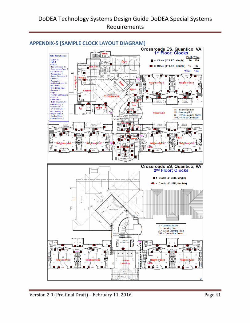
Clocks shall be installed in every room identified in the “clock” column of the IT Connection Matrix (Appendix 2). A clock shall be visible from all locations in the main school corridor, so spacing needs to be determined by designers based on corridor geometry and sight lines, and coordinated (through the DoDEA Area PM) with the School/District. See Appendix 5 for a Sample Clock Layout Diagram.
11.3 INTERCOM
A bi‐directional intercom system is required in occupied rooms (i.e. learning spaces and offices). Intercom systems may consist of loudspeaker communications, handsets, or a push‐talk button with a 2‐way speaker. Each occupied room shall have a capability to contact the main administration desk.
The systems designer is responsible to provide transmit‐receive coverage to occupied spaces. Additional locations shall be determined at design meetings.
The transmit‐receive location shall be near the primary entrance to the room. Intercom and PA speakers shall be provided at exterior learning areas that are immediately adjacent to the school, such as the Art Patio, outdoor classrooms, etc.
Systems designers shall coordinate with the DoDEA Area PM for the basis of design for the intercom system.
11.4 PA SYSTEM
The PA system (a distinct system from the Mass Notification System) shall be integrated into every studio location as a minimum, and other locations as identified in Appendix 2. Additional locations may be determined early in the design process.
PA system design and paging zone identification is the responsibility of the design team and must be included in the design documents. The submittal shall be marked “for government approval” in the specifications. Coordination with the DoDEA Network and proposed phone system is also the responsibility of the systems designer. The PA System must be zone programmable with at least 48‐zones. Training must be provided to the School/District so the local user can modify, delete, or add new zones.
For school opening, zone paging capability must be set‐up to include at least the following zones:
All call (all interior and exterior speakers) All interior speakers

DoDEA Technology Systems Design Guide DoDEA Special Systems Requirements
Version2.0(Pre‐finalDraft)–February11,2016 Page21
All exterior speakers Each neighborhood Each separate instructional area (Art, Music, Info, LIMM/LIMS, Gym, Performance,
Multi‐purpose/Commons, Science, CTE, OT/PT, etc.) Each outdoor classroom/learning area Commons/Performance Other zones as identified by the School/District
Integrate the PA system with the telephone system providing an access security code as well as global and individual zone access. The intent is to allow the Principal to dial the PA controller via any phone, enter a security code, select a zone, and make an announcement. This includes access via wireless or WiFi phones, to provide full telephone and intercommunications throughout the building and campus.
Every speaker must be equipped with user adjustable tap settings or volume control to allow adjustment (without the use of tools or special equipment), after installation, to meet local audibility needs.
Installation of marquees shall also be considered during the design phase to accommodate areas that may be routinely occupied by hearing impaired and special education students.
12.0 AUTOMATED PARENT NOTIFICATION SYSTEM
Where allowed, DoDEA Schools use the “One Call Now” (reverse 911), or equivalent,
notification system that is available without special equipment. Therefore, a special capability
inside the school, other than an operational phone system, is not required.
13.0 BUILDING AUTOMATION SYSTEMS (BAS)
13.1 REQUIRED FUNCTIONS
The BAS, Direct Digital Control (DDC) or Energy Management System (BAS), henceforth referred to as BAS shall be a single, complete, non‐proprietary BAS system. The BAS system must be a complete system (albeit without a front end) suitable for the control of heating, ventilating and air conditioning (HVAC) and other building‐level systems as indicated and shown below:
[1] Refrigerator/Freezer temperature systems. When the alarm condition is sensed,

DoDEA Technology Systems Design Guide DoDEA Special Systems Requirements
Version2.0(Pre‐finalDraft)–February11,2016 Page22
then the designated representative for the refrigerator/freezer system is alerted. [2] Mechanical Systems such as HVAC units. [3] Carbon Dioxide Sensors. [4] Lighting Control Systems. [5] Energy Consumption (metered and sub‐metered). [6] Provide telemetry and feedback. [7] Digital dashboards shall be configured to read data from the BAS.
All BAS control systems must be designed in accordance with UFC 3‐410‐02, Direct Digital Control for HVAC and Other Building Control Systems.
The building control network shall be an Open implementation of BACnet or LonWorks technology using ASHRAE 135 protocol or ANSI/EIA 709.1B communications protocol, respectively, as the only communications protocols, and shall use only BACnet ASHRAE 135 Services or LonMark Standard Network Variable Types (SNVTs) as defined in the LonMark Resource Files, respectively, for communication between BAS Hardware devices and to allow multi‐vendor interoperability.
The building automation system shall be open in that it is designed and installed such that the Government or its agents are able to perform repair, replacement, upgrades, and expansions of the system without further dependence on the original Contractor. This shall include, but is not limited to the following: 1) Install hardware such that individual control equipment can be replaced by similar control equipment from other equipment manufacturers with no loss of system functionality; 2) Necessary documentation (including rights to documentation and data), configuration information, configuration tools, programs, drivers, and other software shall be licensed to and otherwise remain with the Government such that the Government or its agents are able to perform repair, replacement, upgrades and expansion of the systems without subsequent or future dependence on the Contractor.
The following systems are prohibited for new installation: proprietary BAS systems, pneumatic systems or combination BAS/Pneumatic systems. Gateways may be used provided that each gateway communicates with and performs protocol translation for control hardware controlling: 1) A single major component (chiller, boiler); 2) Legacy or existing equipment in a building that is to remain.
BAS Hardware (controller) requirements are as follows: All BAS Hardware: 1) Shall be connected to a control network via the ASHRAE 135 (BACnet), or via TP/FT‐10 ANSI/EIA 709.3 (LonWorks), respectively; 2) Shall communicate over the control network via ASHRAE 135 Service or over the control network via ANSI/EIA 709.1B, for BACnet or LonWorks, respectively; 3) Shall communicate with other BAS hardware using only the ASHRAE 135 (BACnet) or usingonly SNVTs (LonWorks), respectively; 4) Shall conform to the BTL Device Implementation

DoDEA Technology Systems Design Guide DoDEA Special Systems Requirements
Version2.0(Pre‐finalDraft)–February11,2016 Page23
Guidelines or shall conform to the LonMark Interoperability Guidelines (LonWorks) or shall conform to the Interoperability Guidelines (LonWorks); 5) Shall be locally powered (link power over the control network is not acceptable); 6) Shall be fully configurable, without limitation for LONWorks, via standard or user‐defined configuration parameter types (SCPT or UCPT), standard network variable type (SNVT) network configuration inputs (nci), or hardware settings on the controller itself; and 7) For BACnet, analog inputs/outputs must be implemented using ASHRAE 135 requirements, and for LONworks, shall provide input and output SNVTs required to support monitoring and control (including but not limited to scheduling, alarming, trending and overrides of the application). Required SNVTs include but are not limited to: SNVT outputs for all hardware I/O, SNVT outputs for all setpoints, SNVT inputs for overrides of all setpoints, and SNVT inputs for overrides of all hardware Outputs.
Application Specific Controllers (ASCs) for BACnet shall be BTL listed as B‐ASC. LonWorks controllers shall have a fixed factory‐installed application program (i.e. ProgramID) with configurable settings and shall not have the ability to be programmed for custom applications. In addition to the requirements for all BAS Hardware ASCs shall: 1) Be BTL Listed or LonMark Certified unless otherwise approved; and 2) LonWorks controllers shall be configurable via an LNS plug‐in unless otherwise approved.
Application Generic Controllers (AGCs) for BACnet shall be BTL listed as B‐AAC. LonWorks controllers shall have a fixed factory‐installed application program (i.e. ProgramID) with configurable settings and shall not have the ability to be programmed for custom applications. In addition to the requirements for all BAS Hardware, AGCs shall: 1) Have a fixed ProgramID and fixed XIF file and 2) Shall be fully programmable and configurable for the application through one or more LNS plug‐ins unless otherwise approved.
General Purpose Programmable Controllers (GPPCs) are not installed with a fixed factory‐installed application program and must be programmed for the application.
Do not rely on the control network to perform BAS sequence applications unless otherwise approved. Where multiple pieces of BAS Hardware are used to execute one sequence, all BAS Hardware executing that sequence shall be on a common segment and isolated from all other BAS Hardware via a BACnet/IP or CEA‐709.1B Router. For LonWorks, each scheduled system shall accept a network variable of type SNVT_occupancy and shall use this network variable to determine the occupancy mode. If the system has not received a value to this network variable for more than 60 minutes it shall default to a configured occupancy schedule, the occupied mode.
The building automation systems must integrate with existing DoDEA systems for remove monitoring. In some cases, existing DoDEA computers (i.e. School District Superintendent’s

DoDEA Technology Systems Design Guide DoDEA Special Systems Requirements
Version2.0(Pre‐finalDraft)–February11,2016 Page24
Office/DSO facility maintenance computers) that remotely monitor and control multiple school BAS systems may need to have their software upgraded to read BAS systems for a new school; in this case, the construction contractor shall coordinate with the DoDEA Area PM, who will identify the computers that require a software upgrade and will assist with scheduling the contractor a time to provide and upload the software. Note: the software must first be tested and approved by HQ DoDEA (Section 5.7). Where required, the A/E and/or construction contractor shall coordinate with the local Public Works Department, Civil Engineer or Directorate of Public Works on the required process to share BAS system data with the installation via a smart meter.
Prior to the BAS system installation, the following should be submitted for Government approval (also see the BAS System QC Checklist, Appendix 6):
Points Schedules: Submit Points Schedules using the Points Schedule template located at https://eko.usace.army.mil/fa/bas/ for each piece of BAS Hardware. The Points Schedules shall be submitted in hard copy (11”x17”) and electronic format. Electronic submission shall be in AutoCAD, Microstation and Excel format and submitted on CD or DVD.
Control System Schematic diagram and Sequence of Operation for each HVAC system.
Upon completion of the project, the following should be delivered to the Government for acceptance:
eXternal Information Files (XIF), Resource files and Plug‐ins for the completed system.
Point Schedules: Final (as‐built) Points Schedules using the Points Schedule template located at https://eko.usace.army.mil/fa/bas/ for each piece of BAS Hardware. The Points Schedules shall be submitted in hard copy (11”x17”) and electronic format. Electronic submission shall be in [AutoCAD][Microstation][Excel] format and submitted on CD or DVD.
Control System Schematic diagram and Sequence of Operation for each HVAC system. Programming Software: All software, including licensing information and user manuals,
necessary to program GPPCs installed under this contract. Copies of the installed application programs (all software that is not common to every
controller of the same manufacturer and model) as source code compatible with the supplied programming software.
Operation and Maintenance Instructions including procedures for system start‐up, operation and shut‐down, a routine maintenance checklist, and a qualified service organization list.
Quality Control (QC) checklist (Appendix 6) completed by the Contractor's Chief Quality Control (QC) Representative.
Perform a Performance Verification Test prior to system acceptance. During the test, demonstrate to a Government representative that the system performs as specified, including

DoDEA Technology Systems Design Guide DoDEA Special Systems Requirements
Version2.0(Pre‐finalDraft)–February11,2016 Page25
but not limited to demonstrating that the system is Open and correctly performs the Sequences of Operation.
Provide a 1 year unconditional warranty on the installed system and on all service call work. The warranty shall include labor and material necessary to restore the equipment involved in the initial service call to a fully operable condition. Subsequent integration of the building control system into a basewide Utility Monitoring and Control System by the Government or its agents shall not void warranty.
Provide training for the system in accordance with Section 5.4 of this guide.
13.2 COMMUNICATIONS
The communication of BAS systems shall be network based with a centralized monitoring
system located at the DoDEA Area Office or another centralized location identified by HQ IT
ASA (systems designers shall coordinate with the DoDEA Area PM regarding this location). All
servers, equipment, and data related to building automation systems shall reside at the DoDEA
Area or centralized location and not in the local building or campus.
13.3 THERMOSTATS
The desired thermostats shall display room/space temperature and relative humidity levels on a rotating cycle. This provides an indoor air quality survey about every 15‐seconds to be read in the room and on the BAS system. A separate CO2 sensor shall be provided, co‐located with the thermostat.
14.0 SPORTS FIELDS FIBER OPTIC CABLE
Fiber optic cable shall be provided from the school IT main connection point to the athletic pressbox and athletic fields (if required) to support point of sale stations and scoreboards.
Network connectivity must be provided for the following:
[1] Pressbox [2] Concessions [3] Field Houses [4] Sound System [5] Video Capture/Broadcast [6] Scoreboard

DoDEA Technology Systems Design Guide DoDEA Special Systems Requirements
Version2.0(Pre‐finalDraft)–February11,2016 Page26
The style of fiber optic cable shall be determined by the distances to the school and the athletic field being served. OM4 50 micron laser optimized having 4700 MHz*km EMB bandwidth designed for 10 Gb/s, and 100 Gb/s transmission is the preferred type of fiber unless the distance is greater than 300 meters in which case the systems designer should consider using outside plant single mode armor fiber. Fiber connections should be made with LC type connectors.
Direct bury or aerial cable is not permitted. The systems designer shall provide detailed specifications in the document drawings that indicate the correct pathway infrastructure.
15.0 MONITORS AND DISPLAYS
15.1 INTERIOR MESSAGE DISPLAYS
At least one digital LED/LCD message display shall be provided in or near the Commons, or in a common area on each floor/level. The intent of this display is to show scrolling messages about school activities and events. This message display shall be designed to have connectivity to a computer in the main administrative suite. This message display may be co‐located with the energy dashboard.
A LED/LCD display is desired near the food service serving line dedicated to display menus.
LED/LCD displays may be desired in the Multi‐Purpose Room and Performance Space that open to the Commons via operable partition walls. This display shall (1) enable audience members at off‐center viewing angles to see live video‐taped performances/presentations, and/or (2) allow audience members at a long distance to get a better view of live video‐taped performances/ presentations.
LED/LCD message displays shall not be less than 50” flat panel televisions. The contract shall include cabling and mounts for the televisions (televisions shall be mounted at age appropriate heights), with the televisions themselves being provided with FF&E funding. Message displays in the commons/multi‐purpose room areas are typically connected to an individual computer nearby, while message displays in the commons area/each floor are typically able to connect to the data network so messages can be input from the administration area.
15.2 ENERGY DASHBOARDS
Power and data drops, metering and other building infrastructure shall be provided to support an energy dashboard system.

DoDEA Technology Systems Design Guide DoDEA Special Systems Requirements
Version2.0(Pre‐finalDraft)–February11,2016 Page27
A digital LED/LCD Energy Dashboard display shall be provided in each school. There shall be a minimum of one Dashboard display (GFGI), with additional displays considered, budget permitting. The main Dashboard display and supporting computer system shall be placed in or near the Commons, with additional dashboards placed in common areas on each floor/level. Displays shall be a minimum 42 inch flat panel monitor in size.
If budget permits, a touch screen display or kiosk can be provided; it should have the capability to be set in either interactive or non‐interactive mode. Kiosks shall support touch‐screen control and keyboard/mouse control.
At a minimum, the Dashboard display shall have the capability to receive information from the Building Automation System (BAS) and shall have the capability to display information about metered utility system usage, current demand, and sub‐metered systems; for example, information about all electrical, gas and water being consumed by the building on a real time basis (15 minute interval minimum). There shall also be capability to extract data from other data sources on site (such as demonstration solar, demonstration PV, geothermal, solar water heating systems, etc.) and the Dashboard system shall subsequently have the capability to display information about energy generation. The Dashboard system shall be able to present:
[1] Overall building energy consumption [2] Overall building gas consumption (where applicable) [3] Overall building electrical consumption [4] Neighborhood electrical plug load consumption (for each Neighborhood) [5] Neighborhood electrical lighting load consumption (for each Neighborhood) [6] Neighborhood electrical HVAC [7] Overall building water consumption [8] PV Output [9] Solar hot water output [10] Rainfall/weather data
15.3 EXTERIOR ELECTRONIC MARQUEES
Systems designers shall include an exterior electronic marquee display unit, with LED display integrated into the school sign, near the main entrance to new schools. The Marquee display unit shall be connected to the DoDEA Network for content and control.
The main connections required for the marquee are power and data. The data connection is via fiber optic cable terminating on a LC connection patch panel at TR1. The fiber optic cable shall be run to the building telecommunications room TR1. The exterior marquee shall be large

DoDEA Technology Systems Design Guide DoDEA Special Systems Requirements
Version2.0(Pre‐finalDraft)–February11,2016 Page28
enough to be viewed from the street, shall be an off the shelf standard size, and shall have a LC connector or converter box.
The software control of the marquee shall be done from a computer located in the main office reception area (GFGI). Equipment supporting the exterior electronic marquee shall be located in TR1.
All fiber optic cabling shall comply with BICSI OSP (outside plant) standards (OS‐3 single mode fiber optic cable).
16.0 STAGE/PLATFORM/SPECIAL SPACE REQUIREMENTS
16.1 LIGHTING CONTROL
A dedicated lighting and control network shall serve the theatrical, Broadcast Room, and multi‐purpose spaces that require controlled specialty lighting for performances, broadcast production, or public assembly events. These systems shall be included by, and supported after installation, by the project. Spaces with special lighting and control network requirements may include proscenium stages, black box theaters, commons areas, cafetoriums, and video production suites. Functionality must include dimming control of the architectural (house and work) lights, running‐lights and portable performance/production lighting within the envelope of the specific facility. Portable specialty fixtures for stage/studio use shall be included. High‐output long‐life LED‐type stage fixtures are needed where heavy use is anticipated and/or access for lamp maintenance is limited.
The lighting and control system shall include dimmers and load circuit distribution, control devices and control network receptacles. Modular dimmer racks shall be located in a dedicated, conditioned electrical equipment room and shall be floor mounted on a suitable cleaning pad. A wall‐mounted control distribution rack shall be located adjacent to the dimming racks; the control distribution rack shall serve as the central control signal distribution point. Load circuits shall run from the dimmer racks’ architectural lighting fixtures and to receptacles for portable stage lighting fixtures as required for the specific space. Each load circuit shall be served by a dedicated dimmer or relay module as appropriate for the particular load type.
Control components for performance/production lighting shall reside on a dedicated distributed DMX512 (E‐ DMX/DMX) network. Network and DMX receptacles shall be distributed throughout the facility as required to allow control input via theatrical control consoles and output to specialty fixtures and accessories. See Section 16.2 for DMX receptacle locations. The system shall exist on a networked backbone of E‐DMX (CAT 6) cabling. Control of architectural lighting shall include programmable button, slider, and/or LCD stations distributed
DoDEA Technology Systems Design Guide DoDEA Special Systems Requirements
Version2.0(Pre‐finalDraft)–February11,2016 Page29
at entry points, control rooms and backstage locations. Interface between control stations, dimmer racks, and the theatrical systems shall be managed by a dedicated architectural processor and network. The architectural processor shall be capable of addressing all lighting load types in the facility and shall interface with building management systems as required.
The systems designer shall indicate in the project design documents, that separate equipment racks, termination panels, etc., are necessary. Cable infrastructure and access control to the system is typically available to school staff members. DoDEA Network infrastructure does not permit staff access to telecommunication rooms or infrastructure.
16.2 A/V CONTROL INTEGRATION STATIONS
Schools with Performance/stage or Multi‐purpose/platform space require A/V Control Stations for integrated control of lighting, sound, projector/computer, screen, and curtains. The systems designer shall determine (through the DoDEA Area PM) with faculty/staff the need and location for the controls integrated with lighting in a single user interface. These physical locations could be; (1) stage left, (2) stage right, (3) down stage center, and (4) the rear of the audience seating areas at a location with an unobstructed view of the stage. A mobile height adjustable A/V control desk to carry control devices and operate A/V systems during performances shall be provided. See also Section 8.3 for Projector outlet requirements.
16.3 SOUND SYSTEMS
A complete and useable sound system shall be designed for the Performance, Multi‐purpose, Commons, and Gym spaces. For Performance and Multi‐purpose rooms that open via operable wall to the Commons, the sound system must accommodate both spaces but have a capability to be limited to the Performance or Multi‐purpose room. The sound system must support both wired and wireless microphones and have enough channels to support the varied band instrument categories, dependent on grade level of the school. Two microphone connections shall be at each A/V control station, plus additional microphone connections at the stage front and sides. At least two wireless microphone sets shall be provided as part of the sound system. Volume controls shall be provided at each AV Control station. A computer/laptop sound connection shall be provided at each AV Control station. Wireless sound systems are allowed as long as the wireless frequency does not conflict with the DoDEA wireless network. If a wireless system with a wireless control dashboard/tablet is approved, then wired volume control locations at A/V Control Stations may be reduced as coordinated with the project delivery team.
A sound system may be desired in Neighborhoods, based on the geometric configuration of the neighborhoods, to: (1) allow students in two adjacent Studios to hear a single presentation when the operable wall between the Studios is open, (2) allow students in two adjoining

DoDEA Technology Systems Design Guide DoDEA Special Systems Requirements
Version2.0(Pre‐finalDraft)–February11,2016 Page30
Studios and the Hub to hear a single presentation, and (3) allow students in all Studios and the Hub to hear a single presentation. Alternately, a mobile wireless FF&E/outfitting funded Neighborhood sound system may be proposed (see Section 8.1) if the frequencies do not conflict with the DoDEA wireless network, and it is capable to meet the three above Neighborhood sound capabilities desired.
16.4 IT SUPPORT
Systems designers shall determine with faculty/staff (through the DoDEA Area PM) the locations and quantity of network data connectivity. Consideration shall be given to no less than stage left, stage right, down stage center and the rear of the audience/commons area. If A/V control is required, co‐locate the IT connectivity.
16.5 RIGGING AND DRAPERY
Systems shall be designed to offer flexibility in set up and use of stages, multi‐purpose rooms, and Broadcast studios. Designs shall minimize the need for access to overhead equipment via portable ladders.
16.5.A RIGGING: STAGE PLATFORMS
[1] Elementary Schools
Overhead rigging shall consist of battens supporting stage drapery and performance lighting. All battens shall be dead‐hung (fixed) from the overhead structure. Lighting battens above the stage shall integrate high‐output long‐life LED‐type strip lighting. Lighting battens above the seating area providing front light shall integrate high‐output long‐life LED‐type spot lighting.
[2] Middle Schools
Overhead rigging shall consist of battens supporting stage drapery and performance lighting. All drapery battens shall be dead‐hung (fixed) from overhead structure. Lighting battens above the stage shall raise and lower via motorized hoists. Hoists shall incorporate redundant braking; operation shall be by a securable simple pushbutton station. Lighting above the seating area providing front light to the stage shall mount at dedicated catwalks or hoisted motorized battens.
DoDEA Technology Systems Design Guide DoDEA Special Systems Requirements
Version2.0(Pre‐finalDraft)–February11,2016 Page31
[3] High Schools
Overhead rigging shall consist of moveable battens supporting stage drapery and performance lighting. Additional utility battens shall be available to support lightweight scenery and supplemental lighting. All battens shall raise and lower via motorized hoists providing both fixed speed and variable speed options as appropriate to location and use. Hoists shall incorporate redundant braking and secondary safety mechanisms. Operation and position control shall be by an electronic control system.
A dedicated panel shall allow repeatable playback of selected scenes. Catwalks or walking grids are indicated for access and maintenance of equipment installed at structure level. Lighting above the seating area providing front light shall mount at dedicated catwalks.
16.5.B RIGGING: BLACK BOXES, HYBRID STAGES, BROADCAST ROOMS
Catwalks are indicated overhead to mount stage lighting fixtures and to support lightweight temporary scenery. For Broadcast Rooms or other spaces where overhead height is limited, pipe grids may be installed. Care shall be exercised in selecting elevations for these fixed structures to limit hazards associated with use of portable ladders in accessing equipment overhead.
16.5.C DRAPERY – STAGE PLATFORMS
Stage curtains shall be fabricated of specialty fabrics and shall be certified as flame‐retardant. Inherently flame‐retardant polyester velour fabrics are indicated for the majority of stage drapery. Cotton fabrics used for specialty curtains such as cycloramas shall be chemically treated for flame‐retardance. Care shall be taken in sizing and layout of stage drapery systems to maximize the usable stage space and to adequately mask the audience views into the back‐of house area.
[1] Main Setting – Valance and Traveler (colors selected in coordination with the interior design). [2] Masking Leg and Border Sets – quantity as required to adequately mask the stage. Legs shall mount on walk‐along tracks to allow flexible positioning (color: black). [3] Mid‐stage and Upstage Travelers – full stage curtains mounted to hand operated draw traveler tracks (color: black). [4] Cyclorama ‐ for High Schools and Middle Schools – bleached white cotton backdrop mounted at the rear of the stage.

DoDEA Technology Systems Design Guide DoDEA Special Systems Requirements
Version2.0(Pre‐finalDraft)–February11,2016 Page32
16.5.D DRAPERY – BLACK BOXES, HYBRID STAGES, BROADCAST ROOMS
[1] Perimeter black velour masking legs mounted on walk‐along tracks. [2] Broadcast Rooms shall also include a chroma‐ green cyclorama along at least one wall.
17.0 DESIGNER CHECKLIST
The following is a recommended checklist of items for the systems designer to consider as part of the project development. Each item must be addressed in the design documents in a schedule, table, matrix, or other format that can be easily reviewed (see Appendix 4).
Stand‐alone cabling for Special Network systems (separate “Facility Network” OK) Determine location of IWBs and Displays Determine type of phone service from base Phone line capacity Internet services availability (determine path of new OSP fiber cabling; hub‐spoke concept) Integration of phone, bells and clocks with PA system Fire alarm integration requirements Access control requirements (Proximity Card Systems and Access‐Intercom Phone System)
Ensure Compliance with DoDEA’s Physical Security & Antiterrorism Design Guide Mass notification integration requirements Building Automation System (“Facility Network” may carry Special systems) Electronic marquee and energy dashboard locations and requirements PA/Intercom locations PA‐Intercom‐Clock‐Bell system integrated PA system zones Identify systems that shall be located in telecommunications rooms

DoDEA Technology Systems Design Guide DoDEA Special Systems Requirements
Version2.0(Pre‐finalDraft)–February11,2016 Page33
APPENDIX‐1 [INTERACTIVE WHITE BOARD DIMENSIONS]

DoDEA Technology Systems Design Guide DoDEA Special Systems Requirements
Version2.0(Pre‐finalDraft)–February11,2016 Page34

DoDEA Technology Systems Design Guide DoDEA Special Systems Requirements
Version2.0(Pre‐finalDraft)–February11,2016 Page35
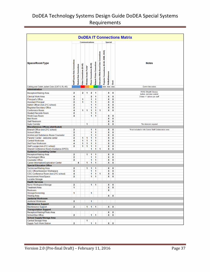
APPENDIX‐2 [IT CONNECTIONS MATRIX]

DoDEA Technology Systems Design Guide DoDEA Special Systems Requirements
Version2.0(Pre‐finalDraft)–February11,2016 Page36
DoDEA Technology Systems Design Guide DoDEA Special Systems Requirements
Version2.0(Pre‐finalDraft)–February11,2016 Page37

DoDEA Technology Systems Design Guide DoDEA Special Systems Requirements
Version2.0(Pre‐finalDraft)–February11,2016 Page38

DoDEA Technology Systems Design Guide DoDEA Special Systems Requirements
Version2.0(Pre‐finalDraft)–February11,2016 Page39
APPENDIX‐3 [SAMPLE NEIGHBORHOOD IT LAYOUT]

DoDEA Technology Systems Design Guide DoDEA Special Systems Requirements
Version2.0(Pre‐finalDraft)–February11,2016 Page40
APPENDIX‐4 [IT SUBMISSION CHECKLIST]
DoDEA Technology Systems Design Guide DoDEA Special Systems Requirements
Version2.0(Pre‐finalDraft)–February11,2016 Page41
APPENDIX‐5 [SAMPLE CLOCK LAYOUT DIAGRAM]

DoDEA Technology Systems Design Guide DoDEA Special Systems Requirements
Version2.0(Pre‐finalDraft)–February11,2016 Page42
APPENDIX‐6 [BUILDING AUTOMATION SYSTEM QC CHECKLIST]
Instructions: Initial each item, verifying that the requirements have been met.
# Description Initials
1 All BAS Hardware is installed on a TP/FT‐10 local control bus.
2
Communication between BAS hardware is only via ASHRAE 135/EIA 709.1B using SNVTs (LonWorks). Other protocols and network variables other than these have not been used.
3 All sequences are performed using BAS software.
4 XIF files, Resource files and Plug‐in's are up‐to‐date and accurately represent the final installed system.
5 Commissioned database has been provided.
6 All software has been licensed to the Government.
7
Local Display Panels (LDPs) have been created for all building systems, including all override and display points indicated on Points Schedule drawings.
8 Final As‐built Drawings accurately represent the final installed system.
9 O&M instructions have been completed and submitted.
10 BACnet or LonWorks Network Services based software was provided.