Embed Size (px)
Citation preview

Document Number: MAN08 PV90-4-OMM-SAS-002

Page 2 of 94
This page was intentionally left in blank.

Operating and Maintenance Manual PV90-4
Page 3 of 94
CONTENTS 1. Introduction ..................................................................................................................................................5
1.1. Revision history ....................................................................................................................................5 1.2. Description............................................................................................................................................5
2. SAFETY ..........................................................................................................................................................5
2.1. Safety Symbols ......................................................................................................................................5 2.2. Important Notes ...................................................................................................................................7
3. SYSTEM DESCRIPTION...................................................................................................................................8
3.1. System Operation .................................................................................................................................8 3.2. Fixed Installation with Standard Base Module .................................................................................. 13 3.3. Fixed Installation with Base Module ................................................................................................. 13 3.3. Fixed Installation with 28VDC Base Module ...................................................................................... 14 3.4. Mobile Hanger Trolley (Horizontal) ................................................................................................... 15 3.5. Mobile Hanger Trolley (Horizontal) with 28VDC Base Module ......................................................... 16 3.6. Mobile Hanger Trolley (vertical) ........................................................................................................ 17 3.7. Bridge Mount ..................................................................................................................................... 18 3.8. Towable Trailer .................................................................................................................................. 19
4. DELIVERY & POSITIONING ......................................................................................................................... 20
4.1. Delivery .............................................................................................................................................. 20 4.2. Packing List ........................................................................................................................................ 20 4.3. Optional Extras .................................................................................................................................. 20 4.4. Storage ............................................................................................................................................... 20 4.5. Unpacking & Moving ......................................................................................................................... 21
4.5.1. Lifting Eyes (optional) ................................................................................................................ 21 4.5.2. Lifting with Base Module ........................................................................................................... 25
4.6. Finding a Suitable Location (Fixed Installation) ................................................................................. 27 4.6.1. Space Planning ........................................................................................................................... 28
4.7. Electrical Installation ......................................................................................................................... 29 4.7.1. Front Door ................................................................................................................................. 29 4.7.2. Internal Protection Panel ........................................................................................................... 30 4.7.3. Gland Plate ................................................................................................................................ 33 4.7.4. Base Module .............................................................................................................................. 34 4.7.5. Electrical Connections ............................................................................................................... 35 4.7.6. Input Mains / Supply.................................................................................................................. 37 4.7.7. 400Hz Output ............................................................................................................................ 38 4.7.8. Remote Control Connections (PV-PIT PCB) ............................................................................... 39 4.7.9. Remote Control / Interlock Connections Fuses ......................................................................... 40
5. COMMISSIONING ...................................................................................................................................... 41
5.1. Operational and Environmental Conditions after Commissioning .................................................... 41 6. SYSTEM OPERATION .................................................................................................................................. 42
6.1. Display ............................................................................................................................................... 42 6.1.1. Output Active - Example ............................................................................................................ 44 6.1.2. Display Metering ........................................................................................................................ 44 6.1.1. Display Menu ............................................................................................................................. 49 6.1.1. Display Menu Structure Chart ................................................................................................... 53 6.1.7. Display Menu – Modifying Settings ........................................................................................... 55 6.1.8. 400Hz Setup - Example .............................................................................................................. 55 6.1.9. Display Alarms ........................................................................................................................... 56
6.2. Start-up/Shut-down Sequence .......................................................................................................... 61

Operating and Maintenance Manual PV90-4
Page 4 of 94
6.2.1. Start-up (For standby/ready state): ........................................................................................... 61 6.2.2. Shut-down (For standby/ready state): ...................................................................................... 61
6.3. Basic Operation ................................................................................................................................. 61 6.3.1. Power-On Procedure (Normal operation, with aircraft): .......................................................... 61 6.3.2. Power-Off Procedure (Normal operation, with aircraft): .......................................................... 61 6.3.3. Aircraft Interlock Safety System ................................................................................................ 61 6.3.4. Civilian / Military Interlock: ....................................................................................................... 62 6.3.5. Software Update Procedure ...................................................................................................... 63 6.3.6. Event Datalogger ....................................................................................................................... 65
7. TROUBLESHOOTING & REPAIR .................................................................................................................. 70
8. SERVICE & MAINTENANCE......................................................................................................................... 73
8.1. Recommended Routine maintenance ............................................................................................... 73 8.2. Air Inlet Filter Replacement ............................................................................................................... 74
8.2.1. Vertical Rotation: ....................................................................................................................... 74 8.2.2. Horizontal Rotation: .................................................................................................................. 76 8.2.3. Filter Cleaning: ........................................................................................................................... 77
8.3. Air Exhaust Filter Replacement ......................................................................................................... 78 8.3.1. Vertical Rotation (with base module): ....................................................................................... 78 8.3.2. Horizontal Rotation: .................................................................................................................. 80
8.4. Pluggable Power Module................................................................................................................... 82 8.5. Fan Replacement ............................................................................................................................... 86 8.6. Warranty ............................................................................................................................................ 91 8.7. Extended Warranty............................................................................................................................ 91 8.8. Maintenance and Backup Service ..................................................................................................... 91
9. TECHNICAL DATA ....................................................................................................................................... 92
10. DISPOSAL INSTRUCTIONS ...................................................................................................................... 93
10.1 Dismantling ........................................................................................................................................ 93 10.2 Disposal.............................................................................................................................................. 93

Operating and Maintenance Manual PV90-4
Page 5 of 94
1. Introduction
1.1. Revision history
Powervamp Ltd Operating and Maintenance Manual PV90-4 (SAS)
Document: MAN08 PV90-4-OMM-SAS-002
Revision: 02
Form: REC02 3610
Owner: EM
Date: 14.01.2020
Table 1: Revision history.
1.2. Description
The PV90-4 system is an Electrical Ground Power Unit designed to service modern aircraft with a 90kVA (Three Phase 200V/400Hz) supply output derived from a utility/mains input (Three Phase 360-480VAC 50/60Hz). A number of different mounting options are available for the system, depending on what best suits the operator and aircraft environment, including Fixed, Mobile Trailer, Trolley and Bridge Mount. In addition, optional outputs are also available including separately controlled twin 400Hz Supplies and a 28VDC Transformer Rectifier Unit to service smaller aircraft with a 28VDC supply suitable for steady state and engine cranking type loads. Key Design Features include:
• Up to 95% Total System Efficiency
• Stainless Steel Enclosure for superior outdoor performance and durability
• AC Inductor & 12 Pulse Rectifier to reduce input Current total harmonic distortion (THDi)
• Advanced Filtering providing a High-Quality Sinewave Output suitable for all known aircraft types (<2% THDv)
• Complies with the latest industry standards for Electrical GSE, including ISO 6858:2017 & MIL-STD 704F.
2. SAFETY
Only qualified electrical personnel familiar with the construction and operation of this equipment and the hazards involved should install, adjust, maintain or repair this equipment. Read and understand this manual in its entirety before proceeding. Failure to observe this precaution could result in severe bodily injury or loss of life.
2.1. Safety Symbols Safety symbols are one of the primary ways to call your attention to the potential hazards associated with the unit operation. For your safety, follow the precautions listed throughout this manual before installation, during operation and periodic maintenance procedures.

Operating and Maintenance Manual PV90-4
Page 6 of 94
Caution!
General risk associated with all aspects of installation, adjustment, maintenance and repair.
Risk of Electric Shock!
Risk specifically related to electrical shock.
Hot Surface!
Risk specicially related to hot surfaces / items which could result in burns.
Heavy Item!
Risk specifically related to lifting of heavy items and the associated dangers.
Risk of Entanglement!
Risk specifically related to moving parts and the potential for entanglement.

Operating and Maintenance Manual PV90-4
Page 7 of 94
2.2. Important Notes
Only qualified electrical personnel familiar with the construction and operation of this equipment and the hazards involved should install, maintain or repair this equipment.
• Read these instructions carefully before operating the system.
• All warnings in this manual must be adhered to.
• All operating instructions should be followed carefully.
• The system requires a three phase and earth input supply. DO NOT operate the system without an earthed input supply.
• This manual should be kept in a safe and secure location and made readily available for use by suitably qualified and authorised personnel.
• Never insert any object into ventilation holes or other openings.
• Ruptured fuses must always be replaced with those of the same type and rating. Failure to do so may present a fire hazard.
• Please refer to the equipment overview, which details the weights and dimensions of the equipment supplied. Observe the rules and regulations governing the lifting of equipment. If in doubt, seek assistance with the lifting and movement of heavy items.
Even when the input AC power is isolated, hazardous live parts exist within the system. Isolate the input mains / supply to the GPU at the local distribution board or feeder pillar, then wait at least 10 minutes for the DC capacitors to discharge before opening any doors or removing any covers.
Take care when moving / lifting the unit with a forklift truck! Position forks as wide as possible for the best stability. Assess each lift carefully to ensure the safety of the driver and any surrounding members of staff / public.
Maximum tow speed for the PV90 Trailer is 25 km/h (15 MPH), failure to adhere to this warning may result in tyre failure and serious damage.
SAFETY IS ALWAYS THE PRIMARY CONCERN

Operating and Maintenance Manual PV90-4
Page 8 of 94
`
3. SYSTEM DESCRIPTION
3.1. System Operation The diagram below shows the overall topology of the PV90-4 Ground Power Unit:
Input Isolator Fitted with terminal shrouds and mechanical door interlock, this ensures maximum user safety as the door cannot be opened until the switch is in the off position. Once this switch is in the on position, the system is in standby ready for use. The input isolator also supplies the system electronics via MCB 1. EMC Filter (PV-FILTER PCB) Conducted emission filtering to conform to emission regulations. Both Input (Rectifier) & Output Filtering circuit is located on the PV-FILTER PCB. The PV-FILTER PCB is located behind the PV-CONTROL PCB (Refer to below images).
AC INPUT
360-480VAC 50/60Hz
AC OUTPUT
200VAC 400Hz (TO AIRCRAFT)
VARIABLE SPEED COOLING FANS
MAIN PSU
INPUT ISOLATOR
EMC FILTER (PV-FILTER PCB)
EMC FILTER (PV-FILTER PCB)
PV-CONTROL PCB
OUTPUT CONTACTOR
AC FILTER CAPACITORS
USER DISPLAY (PV-DISPLAY PCB)
INVERTER TRANSFORMER
INPUT AC CHOKE
12 PULSE TRANSFORMER
PM90-4 POWER MODULE: -RECTIFIER DIODES -DC CAPACITORS -DC CONTACTOR -PV-POWER PCB -INVERTER IGBT
MODULES
ELECTRONICS SUPPLY MCB 1

Operating and Maintenance Manual PV90-4
Page 9 of 94
AC Choke & 12 Pulse Transformer Power factor correction and reduced input current harmonics resulting in less stress on the electrical infrastructure. Power Module (PM90-4) The Power Module contains all power conversion devices for the Rectifier (AC-DC) and Inverter (DC-AC) in a single unit, this reduces the typical mean time to repair and therefore reduces downtime. The power module comprises of the following main components:
• Rectifier Diodes: 6 x Diode Modules to create a 12 Pulse Diode Bridge for forward conduction and rectification of incoming AC supply, supplied via the removable plug PL1.
• DC Capacitors: 4 x 10000uF DC Capacitors creating Bulk DC Storage for smoothing of the DC Bus and connected in parallel by the Rectifier circuit. Creates low ripple DC.
• DC Contactor: Contactor to provide a timed control of the connection of the main DC Bus during supply energization. Bypassed via Soft Start circuit to limit inrush current into the DC Capacitors.
• PV-POWER PCB: For controlling the High Frequency drive circuitry required for the Inverter IGBT Modules to generate a three-line AC Waveform. Communicates via signals & CAN bus to PV-CONTROL PCB via PL2 37 Way Ribbon Cable.
• Inverter IGBT Modules: 6 x IGBT (Insulated Gate Bipolar Transistor) Modules for conversion of DC to AC regulated by the PV-CONTROL/PV-POWER PCB’s.
PM90-4 Power Module
PV-CONTROL PCB

Operating and Maintenance Manual PV90-4
Page 10 of 94
Inverter Transformer & AC Filter Capacitors: A high reactance transformer together with the AC filter capacitors provides a clean isolated 400Hz output to the aircraft. The transformer has a temperature monitoring thermistor, monitored via the PV-CONTROL PCB. EMC Filter (PV-FILTER PCB) Conducted emission filtering to conform to emission regulations. Both Input & Output Filtering circuit is located on the PV-FILTER PCB.
Output Contactor: Controlled from the PV-CONTROL PCB, the contactor is coordinated with the action of the ‘F’ wire from the aircraft. When the user presses the ‘ON’ button, the Inverter starts & this contactor closes and will remain closed for as long as the interlock signal is sustained by the aircraft. If there is no feedback from the aircraft within the 5 second window (Boeing 787 compatible & user adjustable), the contactor is disengaged and the Inverter will turn off. Optional additional Contactor can be fitted for secondary 400Hz or 28VDC Outputs. MAIN PSU: Power supply for the main isolated 24V supply to operate all electronics (PCB’s, Fans etc.) PV-CONTROL PCB: Operates the Fans, Display, communicates to the power module and external inputs/outputs. The image below provides further details regarding the connections and fuses fitted:
• PV-CONTROL SW1 – IO Dip-Switch: 4 switch selections for maintenance:
Switch Function ON OFF
1 Spare
2 Spare

Operating and Maintenance Manual PV90-4
Page 11 of 94
3 Spare
4 Force Bootloader (On start-up)
Enabled Disabled (default)
User Display: A rugged user interface with heavy duty rubber buttons. A large 5.7inch TFT display screen outputs detailed system information complemented by a user friendly “traffic-light” LED indication system to show system status on the Right-Hand Side (Green = System Healthy, Amber = Warning, Red = System Fault).
PV-DISPLAY PCB Display PCB located behind the main User Display:
• PV-DISPLAY SW1 - Menu & Spares Dip-Switch: 6 switch selections for maintenance:
Main Display (5.7Inch TFT Screen)
400Hz Output ON /OFF OR 400Hz Output 1 ON/OFF
400Hz Output ON /OFF OR 400Hz Output 2 / 28VDC Output ON/OFF
Rotary Encoder (Display Navigation)
Traffic Light Status Indication System
Output ON LED’s (Green = ON)
Menu Access Button

Operating and Maintenance Manual PV90-4
Page 12 of 94
Switch Function ON OFF
1 Advanced Options Enabled Disabled (default)
2 Spare
3 Spare
4 Spare
5 Test Mode (Factory Use Only)
Enabled Disabled (default)
6 Force Bootloader (On start-up)
Enabled Disabled (default)
PV-PIT PCB: The PV-PIT PCB provides a convenient terminal set for remote control connections (Cable Carriers or Cable Coil Controls, etc.). One is fitted as standard, an additional PV-PIT PCB can be factory installed for a secondary output (Option).
See Section 4.7.8 for more information.
PV-ID PCB: Two PV-ID PCB’s are present in the unit containing programmable memory (EEPROM) to electronically identify the modules (Unique Serial Number). One is installed next to the PV-CONTROL PCB (for the Main Unit Information) and one is inside the PM90-4 Power Module. The PV-ID PCB also stores the system settings.

Operating and Maintenance Manual PV90-4
Page 13 of 94
3.2. Fixed Installation with Standard Base Module
3.3. Fixed Installation with Base Module Note: Dimensions in mm

Operating and Maintenance Manual PV90-4
Page 14 of 94
3.3. Fixed Installation with 28VDC Base Module Note: Dimensions in mm
Operating and Maintenance Manual PV90-4
Page 15 of 94
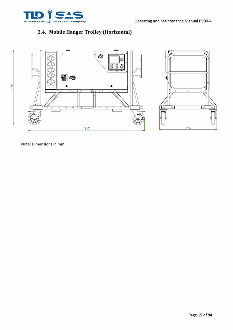
3.4. Mobile Hanger Trolley (Horizontal)
Note: Dimensions in mm

Operating and Maintenance Manual PV90-4
Page 16 of 94
3.5. Mobile Hanger Trolley (Horizontal) with 28VDC Base Module Note: Dimensions in mm

Operating and Maintenance Manual PV90-4
Page 17 of 94
3.6. Mobile Hanger Trolley (vertical)
Note: Dimensions in mm

Operating and Maintenance Manual PV90-4
Page 18 of 94
3.7. Bridge Mount Note: Dimensions in mm

Operating and Maintenance Manual PV90-4
Page 19 of 94
3.8. Towable Trailer
Note: Dimensions in mm

Operating and Maintenance Manual PV90-4
Page 20 of 94
4. DELIVERY & POSITIONING
4.1. Delivery The system will normally be transported on a pallet for ease of transportation. Before accepting delivery, ensure that there is no damage to the system.
Use suitable lifting equipment to offload and move the GPU, do not attempt to manhandle.
4.2. Packing List
• PV90-4 Ground Power Unit
• Door Key
• User Manual
• Output Ferrite Rings x3 (to be fitted to the output cable)
4.3. Optional Extras
• Multi-Length Input Cable with 125A 5 pin Commando Plug
• Multi-Length Output Cable with Aircraft Connector
• PV90-4 Towable Trailer
• PV90-4 Hangar Trolley (vertical or horizontal)
• PV90-4 Base Module or PV90-4 28 VDC Base Module
• PV90-4 Bridge Mount Frame
• Lifting Eyes (x4)
4.4. Storage The system should be stored a cool dry place until ready for installation. Do not stack other items / equipment on top of the systems as this may damage the enclosure. Where possible, the system should remain in its packing.
To prevent condensation and possible damage to electronic components, do not store outdoors or in environments where condensation is likely to occur.
Operating and Maintenance Manual PV90-4
Page 21 of 94
4.5. Unpacking & Moving Remove any shrink wrap and tie straps and dispose of accordingly. Packing should be recycled where possible. Use a forklift truck or pallet truck to move the system into the desired location. For safety, ensure forks are positioned as wide as possible before lifting. If the equipment is moved from a cold environment to the operating location, moisture condensation may occur. Before commissioning the system, it must be completely dry. Therefore, an acclimatisation period of at least two hours should be allowed.
Take care when moving / lifting the unit with a forklift truck! Position forks as wide as possible for the best stability. Assess each lift carefully to ensure the safety of the driver and any surrounding members of staff / public.
Use suitable lifting equipment to remove the GPU from its pallet / crate, do not attempt to manhandle.
4.5.1. Lifting Eyes (optional)
For particular applications, lifting from the top is preferred, for example when armoured cables are pre-installed in ducts directly below the unit, making positioning with a forklift or pallet truck very difficult. This is typical for airport installations. Lifting eyes are supplied loose for fitting by the person responsible for the lift and should be checked carefully for damage prior to installation.
Lifting eyes should be checked in accordance with current legislation!
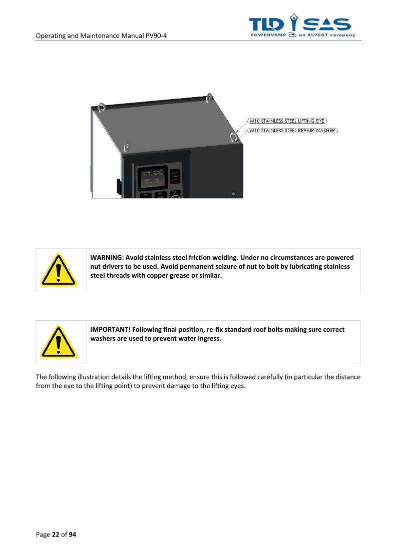
In order to fit the lifting eyes, first remove the standard roof fixing bolts. Ensure washers and bolts are retained for re-fixing following final positioning.
Operating and Maintenance Manual PV90-4
Page 22 of 94
WARNING: Avoid stainless steel friction welding. Under no circumstances are powered nut drivers to be used. Avoid permanent seizure of nut to bolt by lubricating stainless steel threads with copper grease or similar.
IMPORTANT! Following final position, re-fix standard roof bolts making sure correct washers are used to prevent water ingress.
The following illustration details the lifting method, ensure this is followed carefully (in particular the distance from the eye to the lifting point) to prevent damage to the lifting eyes.


Operating and Maintenance Manual PV90-3
Page 25 of 94
4.5.2. Lifting with Base Module
IMPORTANT! For units fitted with the additional base module, the centre of gravity increases (TOP HEAVY!), care must be taken when lifting from below. Ensure forks are positioned are per the following illustrations, failure to adhere to this safety notice could compromise safety and could also cause damage to the unit.
Remove Base Module Front Cover as below:


Operating and Maintenance Manual PV90-3
4.6. Finding a Suitable Location (Fixed Installation) The location of the system is crucial to the correct operation and maintenance of the system. Points to consider:
• Is the location free from flooding?
• Is there sufficient space for air inlet / outlet?
• Is the location level?
• Is there sufficient space for cable entry?
• Is there sufficient space for maintenance?
If the answer to any of the above questions is no then you should reconsider the location. Feel free to contact our technical support team if you are unsure. Please see the back page of this manual for contact details.
Take care when moving / lifting the unit with a forklift truck! Position forks as wide as possible for the best stability. Assess each lift carefully to ensure the safety of the driver and any surrounding members of staff / public.
Use suitable lifting equipment to position the GPU, do not attempt to manhandle.
Typically, the system will dissipate 50W of heat for every 1000W of connected load, adequate airflow / cooling is critical to ensure reliable operation in enclosed spaces.

Operating and Maintenance Manual PV90-4
Page 28 of 94
4.6.1. Space Planning Ensure sufficient space is allowed for around the unit during installation. This will assist with on going maintenance activities.
• A clearance gap of at least 700mm is recommended for the front of the unit to allow the main door to open fully.
• A clearance gap of at least 150mm is recommended on either side of the system for ventilation & maintenance purposes (exhaust filter clearance)
• A clearance gap of at least 500mm is recommended on the rear side of the unit to allow the main filter to be replaced and access to the inverter transformer and filter capacitor section.
See the below image for more detail:

Operating and Maintenance Manual PV90-4
Page 29 of 94
4.7. Electrical Installation
The PV90-4 is fitted with a door interlocked isolator switch, this prevents the door opening when the switch is in the on position. It is advisable to isolate the unit at the supply breaker / fuse prior to opening the door.
4.7.1. Front Door All electrical connections are situated behind the front door, before attempting to open the door, make sure the isolator switch is in the off position, then using the appropriate key (supplied) unlock the door.

Operating and Maintenance Manual PV90-4
Page 30 of 94
Both front and rear doors use the same key, the image to the left provides details of this key for future reference.
4.7.2. Internal Protection Panel The system is fitted with an additional protection panel (IP2Xl) behind the rear door, this provides additional safety for operators when the door is opened. In order to access the electrical connections, this panel must be removed, see illustration below.

Operating and Maintenance Manual PV90-4
Page 31 of 94

Operating and Maintenance Manual PV90-4
Page 32 of 94

Operating and Maintenance Manual PV90-4
Page 33 of 94
4.7.3. Gland Plate The gland plate must be fitted to prevent ingress of water, vermin and hot exhaust air from entering this section of the GPU, failure to do so may result in premature failure of the unit. Note the dimensions for the gland plate aperture as per the below drawing:

Operating and Maintenance Manual PV90-4
Page 34 of 94
4.7.4. Base Module For fixed installations, Powervamp recommend the use of a base module, this allows for the additional room required to install armoured type cables. Often cable ducts are positioned directly below the unit but on occasion there is a requirement for surface mounted cabling. A removable gland plate is provided when installing surface mounted cabling. The gland plate is universal so can be moved to any position (front, back side) to accommodate particular installation requirements.

Operating and Maintenance Manual PV90-4
Page 35 of 94
4.7.5. Electrical Connections The diagram below details the main power input / output connection points and noteworthy items:
1
2
3
4
5
6
7
8
9
10
0

Operating and Maintenance Manual PV90-4
Page 36 of 94
No. Description Connections
1 Main Input Isolator (door interlocked) Input Power (L1, L2 & L3). See 4.3.6
2 Output 1 Contactor (400Hz) 400Hz Output 1 (L1, L2 & L3). See 4.3.7
3 Output 2 Contactor (400Hz/28VDC - Option)
400Hz Output 2 (L1, L2 & L3) OR 28VDC Output. See 4.3.7
4 PV-PIT PCB (Interface Signals) Signal Cable (For External Cable Carrier/Cable Coil Remote Control). 12 Core Per Output Recommended. See 4.3.8
5 MCB1 (Electronics Supply MCB) N/A
6 Main PSU N/A
7 External Communications Unit (Option) For RS-485/Modbus/Ethernet Protocols
8 Anti-Condensation Heater (Option) N/A
9 PV-CONTROL PCB (PV-FILTER PCB located behind)
N/A
10 PM90-4 Power Module N/A

Operating and Maintenance Manual PV90-4
Page 37 of 94
4.7.6. Input Mains / Supply In order to achieve full output power, it is recommended that the input is supplied from a 160A (400V input) / 125A (480V input) fuse or circuit breaker. A smaller input supply can be utilised although this will limit the output load capacity.
It is vital that the correct input voltage is applied to the system; please check the rating label for confirmation prior to connection. See also Section 9.0 Technical Data.
The system has an EMC (electromagnetic conformance) filter; due to the nature of EMC filters there will be some leakage to earth, as such RCD’s (residual current device) are not recommended for the input supply at a rating of less than <50mA.
The system requires a three phase and earth input supply. For safety reasons, do not operate the system without an earthed input supply.
The input cables terminate directly onto the input isolator (L1, L2 & L3) with the earth connection directly to the main earth stud.
L1 L2 L3 PE
INPUT

Operating and Maintenance Manual PV90-4
Page 38 of 94
4.7.7. 400Hz Output As standard, the output neutral is referenced to earth via a neutral / earth link. It is vital that local legislation is followed and therefore in some instances (where the neutral is referenced elsewhere) this link should be removed. The system can be supplied with either one or two 400Hz outputs depending on the requirement. In both instances the output cable is connected directly to the output contactor/s and common neutral busbar. For systems fitted with two outputs, each output is capable of supplying the full load (90kVA), both outputs can be used simultaneously provided the connected load doesn’t exceed the system rating. Note: Output 2 can also be used to feed the Optional 28VDC Output Module.
Additional ferrite rings are supplied loose with the PV90-4 GPU, these are for each 400Hz Output and should be fitted to the output cable/s at the time of installation. These rings help reduce output electrical noise to the aircraft. Note: Ensure all 4 cores (L1, L2, L3 & N) pass through the rings in the same direction.
OUTPUT 2 OUTPUT 1
PE N L1 L2 L3 L1 L2 L3

Operating and Maintenance Manual PV90-4
Page 39 of 94
4.7.8. Remote Control Connections (PV-PIT PCB) The PV-PIT PCB controls most of the remote incoming / outgoing signals. One PV-PIT PCB is fitted as standard and a second when a secondary output is used (Optional). To make connection easier, the image below shows various numbers which correspond with the appropriate explanation / diagram below.
4.7.8.1 Aircraft Interlock Connections ①/②
There is one aircraft interlock connection per output, if only one output is fitted then only ① is used. The diagram below shows further details:
PV-CONTROL PCB

Operating and Maintenance Manual PV90-4
Page 40 of 94
4.7.9. Remote Control / Interlock Connections Fuses Both the PV-PIT & Interlock (Military) 24VDC Supplies are Fused on the PV-CONTROL PCB. Fuse Ratings and details are shown below:
4.7.9.1 USB Data Recording
USB Dongle (optional) mass data storage port, allows additional Data Logging records to be stored. Please contact a sales representative for specific application information.
4.7.9.2 Interface via Link Wireless System
A cloud-based 4G Wireless Communication Monitoring System (Link) (optional) can be provided to suit customer communication needs. Please contact a sales representative for specific application information.
4.7.9.3 Interface via RS232 / RS485 (option)
RS232 / RS485 interface (optional) can be provided to suit customer communication needs. Please contact a sales representative for specific application information.
4.7.9.4 Interface via TCP/IP (option)
LAN / TCP/IP interface (optional) can be provided to suit customer communication needs. Please contact a sales representative for specific application information.

Operating and Maintenance Manual PV90-4
Page 41 of 94
5. COMMISSIONING
5.1. Operational and Environmental Conditions after Commissioning For installations where there is a risk of condensation, the unit must be left switched on (standby mode), this provides optimal conditions for the electronic components and avoids humidity in the form of condensed water from reaching vital parts.
To prevent condensation and possible damage to electronic components, the unit must be switched on (standby mode) at all times.
If for some reason the unit has been left without input power for a period of time, a visual inspection for signs of humidity should be carried out. If humidity is discovered on any of the internal parts, the parts must be left to dry out before completely before input power is applied.
Risk of electric shock! Only qualified engineers should attempt to commission this system, failure to commission the system correctly could invalidate the warranty.
NOTE: The following points are for commissioning purposes only and are not part of the normal ‘Start-up’ / ‘Shut-down’ procedure.
1. Perform a visual check for mechanical damage and loose connectors / connections. 2. For systems supplied on a trolley or trailer, check tyre pressures (where applicable) as well as brake
operation. 3. Ensure that the input supply is connected correctly and securely. 4. Ensure that the output cables are connected correctly and securely. 5. Ensure ferrite rings are fitted correctly to the output cables. 6. Ensure interlock and remote-control cables are connected correctly and securely. 7. Perform relevant dead tests on output cables to confirm no short-circuit between any of the phases and
also earth/ground. 8. Close all doors securely, then turn on the input supply to the system. 9. Check that MCB1 is in the ON position and the EPO is out. 10. Turn on input isolator at the rear of the system. 11. Wait for the system to initialise and for the Display to Activate, showing a Green Tick for Healthy System
Status. 12. The green button can now be pressed to start the inverter. The display should now indicate the correct
inverter (output) voltage. 13. Test system with load bank to confirm output voltage, phase rotation and interlock functions. 14. Setup output line drop compensation with load bank to within standard limits. 115.0VAC @ 72kW load is
recommended. See Display Section for detail regarding setup and line drop compensation settings. 15. Check weather seals, in particular roof bolt seals which may have been removed to fit the lifting eyes. 16. Ensure all internal protection panels are fitted and doors are closed properly.

Operating and Maintenance Manual PV90-4
Page 42 of 94
6. SYSTEM OPERATION
6.1. Display
Buttons
⃝ - Rotary Navigation (Left-Right)
≡ - Access Menu Screen
⃝ - Rotary Navigation (Up-Down) I - Inverter ON
⃝ - Rotary Navigation – Enter (Press) O - Inverter OFF
≡ - Menu Access - - -
Indications (Membrane)
✓ - System OK (Green) Green LED (1) - Power to the aircraft (Output 1)
- Warning (Amber) Green LED (2) -
Power to the aircraft (Output 2)
- System Fault (Red) - - -

Operating and Maintenance Manual PV90-4
Page 43 of 94
Display Icons
-
400Hz Interlock Received (Output Active. Connected to Aircraft)
-
28VDC Interlock Received (Output Active. Connected to Aircraft)
-
400Hz Interlock Not Received (Output Active. Not connected to Aircraft)
-
28VDC Interlock Not Received (Output Active. Not connected to Aircraft)
- System Information
- System Settings
- Datalogger
- Input Settings
- USB Read/Write Firmware Update
- Output Settings
- Fan Healthy
- Fan Failed
The GPU is factory configured to one of the following three modes:
• Single 400Hz Output
• Dual 400Hz Output
• Single 400Hz Output + 28 VDC Output (combination output) The display indicators will differ depending on which of the above configurations are selected. See further details below:

Operating and Maintenance Manual PV90-4
Page 44 of 94
6.1.1. Output Active - Example NORMAL OPERATION – SINGLE OUTPUT ACTIVE – INTERLOCKED
FAULT MODE – REQUIRES ATTENTION / RESET (Alarm will appear with text)
6.1.2. Display Metering The display screen provides useful measurements of all critical parameters which assist the user during setup and fault finding. The various screens are detailed below.

Operating and Maintenance Manual PV90-4
Page 45 of 94
Initialising Screen:
Loading Screen(s):

Operating and Maintenance Manual PV90-4
Page 46 of 94
Screensaver:
When operating, the user can use the Rotary Encoder (turn) to scroll through the various screens: Main Screen 1:

Operating and Maintenance Manual PV90-4
Page 47 of 94
Main Screen 2:
Main Screen 3:
Main Screen 3 (E-GSE Mode):

Operating and Maintenance Manual PV90-4
Page 48 of 94
Main Screen 4:
Main Screen 5:

Operating and Maintenance Manual PV90-4
Page 49 of 94
Main Screen 6:
6.1.1. Display Menu
When operating, the user can use the Menu Button (≡) to access the system parameters and settings:
Navigating through the menu functions is simple, to get started, press the menu button and then use the Rotary Encoder to move the cursor to the appropriate function / setting. Then press the Rotary Encoder down to access that Manu. Each menu entry allows access to a different set of functions. Please examine the figure below for further information on which menu is used to access a certain function. The user can then follow the on-screen commands in order to gain access to that function and make any changes. Main Menu Screen:

Operating and Maintenance Manual PV90-4
Page 50 of 94
System Information Screens:
Datalogger Screens:
USB Screens:

Operating and Maintenance Manual PV90-4
Page 51 of 94
System Settings:
Input Settings:

Operating and Maintenance Manual PV90-4
Page 52 of 94
Output Settings:

Operating and Maintenance Manual PV90-4
Page 53 of 94
6.1.1. Display Menu Structure Chart
Mai
n M
enu
System Information -
Datalogger Event Datalogger -
Power Datalogger -
USB Update Display Firmware -
Update Interface Firmware -
System Settings
Pit Controls 1
Enable On
Off
Start NO
NC
Stop NO
NC
External Enable
Off
NO
NC
90% Switch
Off
NC
NO
Temperature Switch
Off
NC
NO
Pit Controls 2
Enable On
Off
Start NO
NC
Stop NO
NC
External Enable
Off
NO
NC
90% Switch
Off
NC
NO
Temperature Switch
Off
NC
NO
Thermal Settings
Fan Idle Off
On
Fan Boost Off
On
Heater Off
On
Flight Entry Flight Entry Off
On
Display Settings Backlight 5-100%

Operating and Maintenance Manual PV90-4
Page 54 of 94
Time / Date
Time -
Date -
Format
dd/mm/yyyy
mm/dd/yyyy
yyyy/dd/mm
yyyy/mm/dd
Language Language English
Input Settings
Low Input Off
On
Battery GPU Off
On
Input Earth Monitoring
Off
Spare Input 1
Spare Input 2
Output Settings
AC Output
Target A 112.0-119.5VAC
Target B 112.0-119.5VAC
Target C 112.0-119.5VAC
Line Drop A 0-10%
Line Drop B 0-10%
Line Drop C 0-10%
DC Output
Target Voltage 26.0-29.0VDC
Line Drop 0-10%
Current Limit 600-2400A
Interlock
Civillian / Military Civillian
Military
Timeout 3.0-10.0s
Override 1 Off
On
Override 2 Off
On
Output Monitoring
Output Earth Monitoring Off
0-10AAC
Neutral-Earth Relay
Off
Spare Input 1
Spare Input 2
Neutral Supervision 1 Off
1-50VAC
Neutral Supervision 2 Off
1-50VAC
Output Configuration
Output Config
1x 400Hz
2x 400Hz
400Hz + TRU DC
400Hz + Inv DC
Mode Simultaneous
Individual

Operating and Maintenance Manual PV90-4
Page 55 of 94
6.1.7. Display Menu – Modifying Settings During normal operation the system settings cannot be modified and can only be viewed. Adjusting the PV-DISPLAY PCB Dip Switch SW1-1 into the ON position allows the user to modify all settings using the Rotary Encoder. Navigate to the relevant menu and Modify the setting by pressing the Rotary Encoder button and adjusting as necessary.
Warning: Only trained personnel should adjust parameters within this menu. Disabling / adjusting safety features can lead to serious injury.
Ensure PV-DISPLAY PCB SW1-1 is set to the OFF position following initial setup / commissioning.
6.1.8. 400Hz Setup - Example
• Line Drop Compensation This feature automatically adjusts the output voltage to compensate for the voltage drop in the output cable. It is not normally necessary to adjust this setting after the initial commissioning as the setting will be stored within the systems non-volatile memory. We would recommend adjusting this setting when a new cable is installed or when problems with voltage tolerances occur at the aircraft.
This setting must only be adjusted with use of a load bank and calibrated voltmeter, adjustment is not recommended when connected to an aircraft.
o Connect a load bank and apply a reasonable load >50% o Measure voltage at load bank using a calibrated 400Hz voltmeter o Press the Menu Button o Select Output Settings icon o Navigate to the until Line Drop Comp (%) is shown for chosen output (L1, L2 or L3). o Use the Rotary Encoder & Button to increase/decrease Line Drop Compensation percentage
to achieve the correct voltage at the load bank. This must be repeated for each phase. o Press Menu to exit once all necessary adjustments have been made. o Press Menu to return to default screen.
• Output Voltage Adjustment Occasionally the operator may prefer a slightly higher or lower nominal output voltage, for example adjusting the nominal output from 115.0 volts to 115.5 volts.
o Press the Menu Button o Select Output Settings icon o Navigate until Voltage Adjustment is shown for chosen output (L1, L2 or L3). o Use the Rotary Encoder & Button to increase/decrease Output Voltage as required. o Press Menu to exit once all necessary adjustments have been made o Press Menu to return to default screen

Operating and Maintenance Manual PV90-4
Page 56 of 94
Warning: Measure output voltage with a calibrated voltmeter prior to connecting to aircraft.
6.1.9. Display Alarms
The above example shows the default display screen with a system alarm. There are numerous alarms which provide comprehensive system information and diagnostics. The following section is intended to be read in conjunction with Section 6 (Troubleshooting & Repair) As a general rule, please press and hold the red OFF button & see if the unit recovers on its own. The procedures below assume that the engineer shuts the unit down completely before checking any of the electronics described below.
Alarm Description Possible Causes / Suggested Action
System
1 AC-DC
PSU Fault The Main DC PSU Unit Voltage is outside normal parameters or faulty.
Check Input Supply Voltage & phases present. Check MCB 1 is ON Check Electronics PSU is operating (Replace if necessary) Replace PV-CONTROL PCB if problem persists.
2 EPO
Alarm The EPO alarm has been pressed.
The continuity of the EPO path has been broken. Check the continuity of the EPO switch for correct operation. Check that the ‘Output 1 & ‘Output 2’ external control paths are closed. Check continuity of EPO wiring to the PV-PIT PCB. Replace the PV-CONTROL PCB if no other fault found.
3 Fan
Warning
Fan warning means that one of the fan tachometer feedbacks is incorrect. The unit will put the remaining fans to full speed to try to maintain operation.
Press and hold red OFF button to Reset. If one or more fans has a problem then the Fan Warning alarm will latch. Replace fan assembly, if the problem persists then replace the PV-CONTROL PCB.
4 Fan
Fault Both fans have failed, the Inverter is now inhibited.
Press and hold red OFF button to Reset. If one or more fans has a problem then the Fan

Operating and Maintenance Manual PV90-4
Page 57 of 94
Warning alarm will latch. Replace the fan assembly, if the problem persists then replace the PV-CONTROL PCB.
5 Heatsink
Overtemp One of the thermal switches has detected a high temperature.
Turn off the unit, wait 10 minutes for the DC to dissipate completely. Check air filter for clogging / debris, clean if required. If the Fan Warning / Failure alarm is also present then this is the likely cause of the fault. Refer to fan warning / failure below.
6 Transformer
Overtemp One of the thermal switches has detected a high temperature.
Turn off the unit, wait 10 minutes for the DC to dissipate completely. Check air filter for clogging / debris, clean if required. If the Fan Warning / Failure alarm is also present then this is the likely cause of the fault.
7 Neut - Earth
Relay The Neutral/Earth Voltage Relay (Option) has operated.
Check Output Neutral & Earth Connections, plugs and leads for damage. Check earthing and if actual voltage is present with respect to neutral. If no voltage is present, replace PV-CONTROL PCB.
8 Input Earth
Missing The Earth Fault PCB (Option) has detected a missing Earth
Check Input Earth Connection and system is correctly bonded for safety purposes. Do NOT attempt to operate the unit if the earthing conditions are compromised.
9 Output Earth
Fault -
Check Output Neutral & Earth Connections, plugs and leads for damage. Check earthing and if actual voltage is present with respect to neutral. If no voltage is present, replace PV-CONTROL PCB.
Supply
10 Supply Freq
Low The incoming AC Supply Frequency is <46Hz
Check incoming Supply is correct and within system tolerance (See 9. Technical Data)
11 Supply Freq
High The incoming AC Supply Frequency is >66Hz
Check incoming Supply is correct and within system tolerance (See 9. Technical Data)
12 Supply
Undervoltage The incoming Supply (AC/DC) is below tolerance.
Check incoming Supply is correct and within system tolerance (See 9. Technical Data) Check Input Connections from Input Isolator to PV-FILTER PCB and PV-CONTROL PCB. Check MCB 1 is ON. If problem persists, replace PV-CONTROL PCB
13 Supply
Overvoltage The incoming Supply (AC/DC) is below tolerance.
Check incoming Supply is correct and within system tolerance (See 9. Technical Data) Check Input Connections from Input Isolator to PV-FILTER PCB and PV-CONTROL PCB. Check MCB 1 is ON. If problem persists, replace PV-CONTROL PCB
14 Supply Phase
Rotation
The Phase Rotation is Anti-Clockwise. Note: Clockwise phase rotation is only required for the 24 Pulse Rectifier (Option)
Swap any incoming phases to provide Clockwise Phase Rotation.
Rectifier
15 Rectifier Inhibited
The rectifier operation is inhibited by one or more of the following alarms:
• Supply Undervoltage/Overvoltage
• Rectifier DC Imbalance
• Phase rotation
• Fan Failure
• External Disable / Inhibit
All of these alarms come up individually on a scrolling basis - which will point to the cause of this alarm – please refer to that section of this table. Some alarms such as AC-DC PSU fault may have resulted from a short interruption of the mains

Operating and Maintenance Manual PV90-4
Page 58 of 94
• EPO Alarm / supply & can be reset by pressing and holding the red OFF button
16 Rectifier No DC Feedback
DC bus voltage is not present when expected.
Check incoming Supply is correct and within system tolerance (See 9. Technical Data) Press and hold red OFF button, if the fault persists then replace the power module.
17 Rectifier Soft Start Timeout
The Soft Start Contactor inside the Power Module hasn’t opened/closed as expected.
Press and hold red OFF button, if the fault persists then replace the power module.
18 Rectifier DC
Undervoltage DC bus voltage is below maximum level.
Check incoming Supply is correct and within system tolerance (See 9. Technical Data) Press and hold red OFF button, if the fault persists then replace the power module.
19 Rectifier DC Imbalance
DC Imbalance present on Power Module internal DC bus
Press and hold red OFF button, if the fault persists then replace the power module.
20 Rectifier DC Overvoltage
DC bus voltage is above maximum level. Press and hold red OFF button, if the fault persists then replace the power module.
21 Rectifier DC
Ripple
DC bus ripple voltage is above maximum level.
Press and hold red OFF button, if the fault persists then replace the power module.
Inverter
22 Inverter
DC GPU Alarm N.B: For Future Development N.B: For Future Development
23 Inverter DC Low
DC bus voltage is below minimum level to operate the Inverter.
This alarm would normally appear with other alarms, go to their appropriate section to resolve:
• Supply Undervoltage / Overvoltage
• Overload
• No DC Feedback
• AC-DC PSU Fault
24 Inverter
DC Overvoltage DC bus voltage is above maximum level.
Press and hold red OFF button, if the fault persists then replace the power module.
25 Inverter
DC Undervoltage
DC bus voltage is below maximum level.
Check incoming Supply is correct and within system tolerance (See 9. Technical Data) Press and hold red OFF button, if the fault persists then replace the power module.
26 Inverter Elec
Overtemp One of the thermal switches has detected a high temperature.
Turn off the unit, wait 10 minutes for the DC to dissipate completely. Check air filter for clogging / debris, clean if required. If the Fan Warning / Failure alarm is also present then this is the likely cause of the fault.
27 Inverter
IGBT Fault The Inverter power section monitoring has picked up a fault.
Generally, this could only occur if an inadvertent short-circuit was put on the output cable. If there is no outgoing load issue, change the power module.
28 Inverter
NBPT Event The system has detected a NBPT (No Break Power Transfer) with an Aircraft
Generally, this shouldn’t cause a trip and is useful for maintenance and monitoring purposes. If problem persists, replace the power module followed by the PV-CONTROL PCB.
29 Inverter
Overload The Inverter power section monitoring has picked up a fault.
Generally, this could only occur if an inadvertent short-circuit was put on the output cable. If there is no outgoing load issue, change the power module.

Operating and Maintenance Manual PV90-4
Page 59 of 94
30 Inverter
Overvoltage
The power module has detected an out of spec voltage & has shut down to protect the load.
Connect a load bank & monitor the load terminals for correct voltage under all loads. Change the power module if a fault is found. Check AC Output Filter Capacitors for 340uF per phase, replace if necessary.
31 Inverter
Undervoltage
The power module has detected an out of spec voltage & has shut down to protect the load.
Connect a load bank & monitor the load terminals for correct voltage under all loads. Change the power module if a fault is found. Check AC Output Filter Capacitors for 340uF per phase, replace if necessary.
32 Inverter
PSU Fault The Inverter PSU level is outside normal parameters.
Press and hold red OFF button, if the fault persists then replace the power module.
33 Inverter
Short Circuit The Inverter power section monitoring has picked up a fault.
Generally, this could only occur if an inadvertent short-circuit was put on the output cable. If there is no outgoing load issue, change the power module.
Output 1
34 Interlock 1
Missing The Aircraft Interlock Signal is missing
Ensure Plug is fully inserted into Aircraft with Auxiliary/Interlock supply available. Check continuity of interlock wires (E and F) between the output power plug and the PV-PIT PCB. With aircraft interlock signal active, check for 28 VDC between output neutral and the F Pin of the Interlock plug on the PV-PIT PCB. If 28 VDC is present but display fails to show interlock LED, replace PV-CONTROL PCB.
35 Interlock 1
Lost The Aircraft Interlock Signal is lost
Ensure Plug is fully inserted into Aircraft with Auxiliary/Interlock supply available. Check continuity of interlock wires (E and F) between the output power plug and the PV-PIT PCB. With aircraft interlock signal active, check for 28 VDC between output neutral and the F Pin of the Interlock plug on the PV-PIT PCB. If 28 VDC is present but display fails to show interlock LED, replace PV-CONTROL PCB.
36 Interlock 1 Overridden
- Activated by User. Automatically disables after Output Power is turned OFF.
37 90% Switch 1
Lost The 90% Switch Signal (Optional) is lost
Ensure Plug is fully inserted into Aircraft. Check operation of 90% Microswitch (Aviation Plug). Check Continuity of 90% Control Lines from Plug to PV-PIT PCB. If Continuity is good and 24VDC Signal is present and closed on the 90% lines, replace PV-CONTROL PCB
38 Temp Switch 1
Lost The External Temperature Switch Signal (Optional) has been lost.
Check operation of Temperature Microswitch (Aviation Plug). Check Continuity of Temp Control Lines from Plug to PV-PIT PCB. If Continuity is good and 24VDC Signal is present and closed on the Temp lines, replace PV-CONTROL PCB.

Operating and Maintenance Manual PV90-4
Page 60 of 94
39 Neutral
Voltage 1 The Neutral Sense Wire (Z Wire) has exceeded the programmed limit
Check Z Wire for voltage – Aviation Cable Assembly/Plug may be damaged or with a ruptured Neutral Pin. Replace as required. Check Continuity of Z Wire Control Lines from Plug to PV-PIT PCB. If Continuity is good and no voltage is detected, replace PV-CONTROL PCB.
Output 2
40 Interlock 2
Missing The Aircraft Interlock Signal is missing
Ensure Plug is fully inserted into Aircraft with Auxiliary/Interlock supply available. Check continuity of interlock wires (E and F) between the output power plug and the PV-PIT PCB. With aircraft interlock signal active, check for 28 VDC between output neutral and the F Pin of the Interlock plug on the PV-PIT PCB. If 28 VDC is present but display fails to show interlock LED, replace PV-CONTROL PCB.
41 Interlock 2
Lost The Aircraft Interlock Signal is lost
Ensure Plug is fully inserted into Aircraft with Auxiliary/Interlock supply available. Check continuity of interlock wires (E and F) between the output power plug and the PV-PIT PCB. With aircraft interlock signal active, check for 28 VDC between output neutral and the F Pin of the Interlock plug on the PV-PIT PCB. If 28 VDC is present but display fails to show interlock LED, replace PV-CONTROL PCB.
42 Interlock 2 Overridden
- Activated by User. Automatically disables after Output Power is turned OFF.
43 90% Switch 2
Lost The 90% Switch Signal (Optional) is lost
Ensure Plug is fully inserted into Aircraft. Check operation of 90% Microswitch (Aviation Plug). Check Continuity of 90% Control Lines from Plug to PV-PIT PCB. If Continuity is good and 24VDC Signal is present and closed on the 90% lines, replace PV-CONTROL PCB
44 Temp Switch 2
Lost The External Temperature Switch Signal (Optional) has been lost.
Check operation of Temperature Microswitch (Aviation Plug). Check Continuity of Temp Control Lines from Plug to PV-PIT PCB. If Continuity is good and 24VDC Signal is present and closed on the Temp lines, replace PV-CONTROL PCB.
45 Neutral
Voltage 2 The Neutral Sense Wire (Z Wire) has exceeded the programmed limit
Check Z Wire for voltage – Aviation Cable Assembly/Plug may be damaged or with a ruptured Neutral Pin. Replace as required. Check Continuity of Z Wire Control Lines from Plug to PV-PIT PCB. If Continuity is good and no voltage is detected, replace PV-CONTROL PCB.

Operating and Maintenance Manual PV90-4
Page 61 of 94
6.2. Start-up/Shut-down Sequence
Only trained personnel should operate this equipment.
Ensure correct installation prior to applying power for the first time - voltage, phase rotation and frequency MUST be within tolerance, see Section 9.0 Technical Data within this manual for further information.
6.2.1. Start-up (For standby/ready state): 1. Check that emergency stop button has been released and that MCB1 is in the ON position. 2. Turn on the main isolator. 3. Allow 10-20 seconds for the system to initialise before pressing the green button. Check that the Traffic
Light “Tick” LED (Green) is illuminated and no alarms are present. The system is now ready for use.
6.2.2. Shut-down (For standby/ready state): 1. Press the red (off) button. 2. Turn off the main isolator. 3. Allow 10 minutes for the DC to discharge internally before opening any doors. Note: If the unit is switched off & on again within a 2-minute period, false alarms may be displayed, in this event press and hold the red OFF (0) button to reset the display alarms.
6.3. Basic Operation
6.3.1. Power-On Procedure (Normal operation, with aircraft):
1. Fully insert aircraft connector into aircraft receptacle. 2. Press the OUTPUT ON (Green button - I). The Aircraft Interlock symbol will now change colour from
Red to Green on the display if the unit is connected to an aircraft.
6.3.2. Power-Off Procedure (Normal operation, with aircraft):
1. Press the OUTPUT OFF (Red button - O). 2. Disconnect output cable from the aircraft.
6.3.3. Aircraft Interlock Safety System This GPU incorporates an interlock safety system which disconnects the output power if the interlock signal from the aircraft is lost. When the ‘ON’ button is pressed, the inverter will start and supply power to the aircraft, if after 5 seconds the system does not sense an interlock signal from the aircraft, the output will disconnect. For service, maintenance and test purposes, the interlock system can be overridden from the display panel. To ensure personal health and safety, the ground power unit automatically returns to its initial interlock mode, once it receives the interlock signal from the aircraft.

Operating and Maintenance Manual PV90-4
Page 62 of 94
The aircraft interlock safety system should only be overridden for service and maintenance by qualified electrical personnel.
Selecting interlock override will cause the pins on the aircraft connector to become live if power is turned on, appropriate precautions should be taken when handling the aircraft connector.
If power disconnects after 5 seconds, first check the aircraft connector is fully engaged and the correct interlock type (military or civilian) is selected. Note: An “Interlock Missing” Alarm will be shown in this event. If necessary, the interlock can be overridden by going to the ‘Interlock Settings’ in the ‘Output Settings’ Menu (only adjustable if Dip-switch SW1-1 is selected to ‘ON’ on the PV-DISPLAY PCB) The interlock override will reset when the ‘OFF’ button (Red) is pressed or when the input power is disconnected.
6.3.4. Civilian / Military Interlock: During factory testing, the interlock is set to Civilian as the default. If power disconnects after 5 seconds, first check the aircraft connector is fully engaged and the correct interlock type (military or civilian) is selected. Note: Military Interlock arrangement is an Optional Extra and requires an additional PSU to be fitted by the Factory.

Operating and Maintenance Manual PV90-4
Page 63 of 94
6.3.5. Software Update Procedure The PV90-4 Control PCB and Display operating software can be upgraded by saving the latest version onto a standard USB drive. To upgrade the PV-DISPLAY PCB please insert the USB drive into the USB port located on the back of the User Display and follow the instructions below. To upgrade the PV-CONTROL PCB please insert the USB drive onto the designated USB port on the PV-CONTROL PCB and follow the instructions below.
Update Software – Step 1 From the Main Menu Screen, please select the USB Menu Icon and then press the rotary encoder down in order to access the software update functionality.
Update Software – Step 2 From the USB configuration menu please select the “Update Display Firmware” option to upgrade display software or select the “Update Interface Firmware” to upgrade the Control PCB software and then press the rotary encoder down to access the menu.
Update Software – Step 3 The system will verify the external media is present. Please ensure the USB drive is inserted into the relevant USB port and wait for the software update process to begin.

Operating and Maintenance Manual PV90-4
Page 64 of 94
Update Software – Step 4 The software will then search a file of higher version than the current version which starts with filename “PV904-DIS-Vxx” or “PV904-INT-Vxx” where xx represents the software version number. Note: If the file with right filename not present onto the USB drive, it will display the message “File Not Found”. If the file with higher version not found, it will display the message “No New Firmware Found”.
Update Software – Step 5 Before upgrading the software, unit will verify that the data present onto the file is correct and not corrupted. If the file verification is failed, please try again by ensuring the correct file is present on the USB drive and follow the steps again.
Update Software – Step 6 If the unit is verified that all of the required software is present onto the USB, it will begin the update. During the update the display will indicate the progress of the update. Note: Do not exit this menu while software update process is ongoing. Restart the Unit or exit out from this menu will stop the software update.

Operating and Maintenance Manual PV90-4
Page 65 of 94
Update Software – Step 7 To confirm that the new software has been downloaded, the Display Version / Interface Version shown on this screen should match the new software version.
Note: As a failsafe, both the PV-DISPLAY & PV-CONTROL PCB’s have the facility to force the system to carry out the software update process. This is initiated by putting the SW-1 Dipswitch 4 (IO-PV-CONTROL PCB) or SW-1 Dipswitch 6 (PV-DISPLAY PCB) into the Enabled position and re-energising the system. If this operation is carried out, the Dipswitch must be returned to the default Disabled position prior to being put into service.
6.3.6. Event Datalogger The PV90-4 Ground Power Unit features the ability to record up to a maximum of 1000 of the most recent events/alarms occurred in time. When the limit is reached, the firmware will begin to delete the oldest record to store the most recent one. It records the Date/Time of both when event is occurred and also when the event is cleared. It also records all the useful measurements, whole unit configuration and the status of the system at the time of event. The PV90-4 also provides the separate “Event log” and “Data Download” display menu screens to help user to navigate through the event log data onto the display or to download the recorded event log data to the external USB and view it on a PC. When downloading the data to the USB, the firmware
will create the new folder if it does not exist and each time create a new file named in time/date
reference and save the files inside the folder to keep all the event log data together. Event Log Screen The Event Log Screen will display the recorded events starting from the most recent first. The user can then move the rotary encoder clockwise/anticlockwise to scroll backwards and forwards in time through the events. Note: there may be a delay in scrolling when new data is being stored.

Operating and Maintenance Manual PV90-4
Page 66 of 94
Viewing the Event Log Data on a PC If the USB data logger facility is being used, first safely remove the USB device and connect it to a PC. Open the USB Drive folder and browse to the Eventlog folder and open the log file in a compatible Spreadsheet/CSV file format viewing software. Each file name contains the date and time of when it was created. The first column of the data contains the date and time of each record. Note, depending on the software platform used, it may hide the seconds value, to display this please ensure the custom format of the data column is as follows: dd/mm/yyyy hh:mm:ss The proceeding columns contains:
• The information about which event has occurred at that time.
• The system status, output status and configuration of the whole unit.
• The information about the input supply voltages and line drops at each phase. The output frequency,
Average Voltage, Total Power, Total Load etc.
• Any active error messages and system alarms.

Operating and Maintenance Manual PV90-4
Page 67 of 94
Data Menu Access
Main Menu From the Main Menu Screen, please select the Datalogger Menu Icon and then press the rotary encoder down in order to access the Datalogger functionality.
Datalogger Menu From the Datalogger Menu Screen, please select the Event Log Menu Icon to view the recorded events.
Event Log View Menu The Event log view screen displays all the recorded events. The user can then move the rotary encoder clockwise/anticlockwise to scroll backwards and forwards in time through the events.

Operating and Maintenance Manual PV90-4
Page 68 of 94
Data Download From the Main Menu Screen, please select the USB Menu Icon and then press the rotary encoder down in order to access the “Data Download” functionality.
Data Download From the USB configuration menu please select the “Data Download” option and then press the rotary encoder down to start the Event log data download process.
Data Download Please insert the USB drive to the back of the unit display and ensure that the power to the unit is not interrupted during this process.

Operating and Maintenance Manual PV90-4
Page 69 of 94
Data Download The firmware will first create a folder
if it does not exist and then create
the file inside the folder on USB to store the Event log data.
Data Download The firmware start storing the Event log data to the file. The data is stored as a comma separated variable (csv), which can be read by Microsoft Excel. During the storage of data to the USB, the display will indicate the user about the progress. Note: Please do not exit this menu while process is ongoing. Restart the Unit or exit out from this menu will stop the process.
Data Download Data Download is complete, the user can press the exit menu button.

Operating and Maintenance Manual PV90-4
Page 70 of 94
7. TROUBLESHOOTING & REPAIR
Only qualified electrical personnel familiar with the construction and operation of this equipment and the hazards involved should install, maintain or repair this equipment.
Isolate the input supply to the GPU at the local distribution board or feeder pillar, then wait at least 10 minutes for the DC capacitors to discharge before opening any doors or removing any covers.
The fans are exposed when the rear door is open, do not open the any doors without isolating the unit.
The table on the following page details a list of all system alarms with suggested corrective actions in priority order.

Operating and Maintenance Manual PV90-4
Page 71 of 94
The following section is intended to be read in conjunction with Section 6.1.9 (Display Alarms) – which gives a more detailed description of the alarm and corrective actions.
Alarm Corrective Action (In Prioritised Order – 1, 2, 3…) Mains / Supply Fail 1 2 4 3 5 8 7 6 9 10
Rectifier Inhibited 1 2 4 3 5 6 7
Supply Phase Rotation 1 2 4 6 5 3 7 8
Supply Freq Low/High 1 2 5 3 4 8 7 6 9 10
Supply Under/Overvoltage 1 2 5 3 4 8 7 6 9 10
Rectifier DC Undervoltage 1 2 3 4 5 6
Rectifier DC Overvoltage 1 2 3 4 5 6
Rectifier DC Imbalance/Ripple 1 2 3 4 5 6
Rectifier No DC Feedback 1 2 3 4 5 6
Inverter Undervoltage 1 2 3 5 7 4 6 8
Inverter Overvoltage 1 2 3 5 7 4 6 8
Inverter Overload/Short 2 3 4 1 5 6
Inverter IGBT Fault 1 2 6
Neutral Voltage 1 / 2 4 1 2 3 5 6
90% Switch 1/ 2 3 1 2 4 5
Temp Switch 1 / 2 1 5 6 2 3 4 6 8
Ambient Overtemp 1 5 6 2 3 4 6 8
Transformer Overtemp 1 5 6 2 3 4 6 8
Heatsink Overtemp 1 5 6 2 3 4 6 8
EPO Alarm 1 4 3 2 5 6
Fan Warning 2 5 1 6 3 4 7 8
Fan Fault 2 5 1 6 3 4 7 8
AC-DC PSU Fault 1 2 3 4 6 5 7 8
Pre
ss a
nd
ho
ld r
ed O
FF B
utt
on
(0
)
Ch
eck
Dis
pla
y fo
r A
dd
itio
nal
Ala
rms
Ch
eck
Inp
ut
Sup
ply
Dep
ress
Em
erge
ncy
Sto
p B
utt
on
Ch
eck
MC
B 1
is O
N
Ch
eck
Inve
rter
Vo
ltag
e vi
a D
isp
lay
Ch
eck
Sup
ply
Vo
ltag
e Fe
ed
bac
k o
n t
he
Dis
pla
y is
Pre
sen
t an
d C
orr
ect
Ch
eck
Inp
ut
Vo
ltag
e an
d F
req
ue
ncy
are
wit
hin
To
lera
nce
Rep
lace
Fan
Ass
emb
ly
Rep
lace
th
e P
ow
er M
od
ule
Rep
lace
AC
Filt
er C
apac
ito
rs
Ch
eck
for
Fan
Fai
lure
Ala
rm, V
isu
al C
hec
k o
f th
e Fa
ns
Let
the
Un
it C
oo
l Do
wn
, th
en R
eset
+ S
tart
Rem
ove
Lo
ad a
nd
Res
et t
he
Syst
em
Rep
lace
PV
-CO
NTR
OL
PC
B
Ch
eck
Ne
utr
al E
arth
Lin
k is
Fit
ted
Ch
eck
Wir
ing
of
the
Swit
ch
Ch
eck
Ou
tpu
t C
able
Insu
lati
on
an
d C
on
tin
uit
y.
Ch
eck
Air
Filt
ers
are
Cle
an a
nd
Cle
ar o
f O
bst
ruct
ion
s
Test
th
e fa
ns
for
op
erat
ion
. Ch
eck
Fuse
15
on
th
e P
V-C
ON
TRO
L P
CB
.
Ch
eck
all W
irin
g to
PV
-CO
NTR
OL
PC
B f
or
any
Loo
se o
r C
ross
ed
Co
nn
ecti
on
s R
epla
ce D
isp
lay
Ref
er t
o S
ecti
on
6.1
.9 f
or
Furt
her
Det
ail
Cal
l Ser
vice
an
d M
ain
ten
ance
De
par
tmen
t

Operating and Maintenance Manual PV90-4
Page 72 of 94
Fault Corrective Action (In Prioritised Order – 1, 2, 3…) No Display Indication 2 3 1 4 5 6
Interlock Missing/Lost 4 2 1 3 5
Rectifier Soft Start Timeout
1 2 5
3 4 6
Pre
ss a
nd
ho
ld r
ed O
FF B
utt
on
(0
)
Ch
eck
Dis
pla
y fo
r A
dd
itio
nal
Ala
rms
Ch
eck
/ R
epla
ce U
SB D
on
gle
Ch
eck
Exte
rnal
Inh
ibit
/ C
on
tro
l In
pu
t
Ch
eck
Fuse
s o
n P
V-C
ON
TRO
LPC
B (
Fuse
s F1
2, 1
3)
Rep
lace
Po
wer
Mo
du
le
Ch
eck
Sup
ply
Vo
ltag
e Fe
ed
bac
k o
n t
he
Dis
pla
y is
Pre
sen
t an
d C
orr
ect
Ch
eck
Inp
ut
Vo
ltag
e an
d F
req
ue
ncy
Ch
eck
Fuse
s o
n P
V-C
ON
TRO
L P
CB
(Fu
ses
F8 &
F6
)
Rep
lace
PV
-CO
NTR
OL
PC
B
Ch
eck
Wir
ing
of
the
Swit
ch
Ch
eck
Ou
tpu
t C
able
Insu
lati
on
an
d C
on
tin
uit
y.
Ch
eck
Air
Filt
ers
are
Cle
an a
nd
Cle
ar o
f O
bst
ruct
ion
s
Ch
eck
Do
or
is C
lose
d C
orr
ectl
y
Ch
eck
all W
irin
g to
PV
-CO
NTR
OL
PC
B f
or
any
Loo
se o
r C
ross
ed C
on
nec
tio
ns
Rep
lace
Dis
pla
y
Ref
er t
o S
ecti
on
6.1
.9 f
or
Furt
her
Det
ail
Cal
l Ser
vice
an
d M
ain
ten
ance
De
par
tmen
t

Operating and Maintenance Manual PV90-4
Page 73 of 94
8. SERVICE & MAINTENANCE NOTE: IT IS ESSENTIAL THAT THIS EQUIPMENT BE REGULARLY CHECKED & TESTED BY QUALIFIED & COMPETENT SERVICE ENGINEERS. PLEASE CONTACT OUR SERVICE DEPARTMENT FOR MORE INFORMATION/DETAILS.
Only qualified electrical personnel familiar with the construction and operation of this equipment and the hazards involved should install, maintain or repair this equipment.
Isolate the input supply to the GPU at the local distribution board or feeder pillar, then wait at least 10 minutes for the DC capacitors to discharge before opening any doors or removing any covers.
8.1. Recommended Routine maintenance All systems should be checked regularly in accordance with current legislation. The check-list below details Powervamp’s recommended check / test schedule which should be followed for safety as well as ensuring equipment warranty remains intact. Daily checks are aimed at operators / ramp staff, any faults should be reported immediately.
Check Type
Check Item Daily Monthly 6 Monthly
General
Display for Green LED, No Alarms
Air Filters are Clean
Inspect Unit for Physical Damage
Check Ground Fixing Bolts (if applicable)
Wheels & Brakes (if applicable)
Cabinet Door Locks
Cabinet Door Hinges
Cabinet Door / Roof Weather Seals
Information / Safety Decals
Electrical
Input Isolator Switch Functional Test
Emergency Stop Functional Test
Aircraft Leads (basic check)
Aircraft Connectors (basic check)
Aircraft Leads (comprehensive check)
Aircraft Connectors (Comprehensive check)
Earth Bonding
Output Cable Insulation
Check all Electrical Connections are Tight
Load Bank & Interlock Functionality Test

Operating and Maintenance Manual PV90-4
Page 74 of 94
8.2. Air Inlet Filter Replacement
Only qualified electrical personnel familiar with the construction and operation of this equipment and the hazards involved should install, maintain or repair this equipment.
The PV90-4 utilises fans to keep critical components cool, this requires airflow into the enclosure via the louver door and associated air filter. This filter will become blocked over time, the actual time depends on environmental conditions. The filter should be inspected regularly and replaced or cleaned when required. The filter is visible from the outside of the unit, look up through the louver door, a flashlight may be required. The PV90-4 can be supplied in either vertical or horizontal rotation, this will determine the inlet louver type. There are different methods for replacing the filter depending on the louver type.
8.2.1. Vertical Rotation: In order to change the filter, the louver door must be opened, this requires a panel key (supplied with unit). The louver door is fitted with a mechanical stopper, this prevents the door from fully opening, while still allowing just enough room for the filter cartridge to be removed. This feature allows the filter to be changed without isolating the unit, note that this procedure should only be attempted when the unit is in standby. Do not attempt in adverse weather conditions.
1. Isolate unit or ensure unit is in standby (fans running slowly). 2. (Newer models): Open louver door utilising panel key (supplied) OR disconnect the Filter fixing panel
bolts as shown below:

Operating and Maintenance Manual PV90-4
Page 75 of 94
3. Only the front mesh panel needs to be removed to access the filter cartridge. Replace with new cartridge or wash as required, then follow steps 1-2 in reverse.

Operating and Maintenance Manual PV90-4
Page 76 of 94
8.2.2. Horizontal Rotation: In order to change the filter, the louver door must be opened, this requires a panel key (supplied with unit). The louver door is not fitted with a mechanical stopper, for safety reasons the unit should be isolated (switched off) before attempting to change the filter. Do not attempt in adverse weather conditions.
Isolate the input supply to the GPU by switching off the Input Isolator [S1], then wait at least 10 minutes for the DC capacitors to discharge before opening any doors or removing any covers.
1. Isolate unit by switching off the input isolator. 2. Open louver door utilising panel key (supplied) and secure louver door in open position with door
stay provided.
3. Slide out filter cartridge by first pushing up (spring loaded) and then towards the unit to bypass the catch.

Operating and Maintenance Manual PV90-4
Page 77 of 94
4. Completely remove cartridge. 5. Replace with new cartridge, then follow steps 1-5 in reverse.
8.2.3. Filter Cleaning: Remove retainer bar by pressing into filer media (stud fixing), then slide retainer bar diagonally as shown in the illustration below. Replace filter media or thoroughly dust / vacuum until clean. Time permitting, the filter media can be washed with water, take care not to install when wet as this could cause serious damage to the unit. Reassemble cartridge and follow steps 1-5 in reverse.
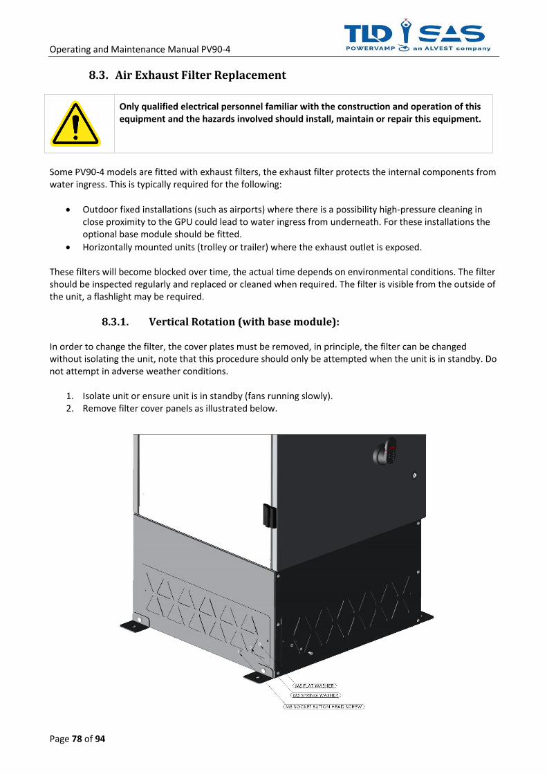
Operating and Maintenance Manual PV90-4
Page 78 of 94
8.3. Air Exhaust Filter Replacement
Only qualified electrical personnel familiar with the construction and operation of this equipment and the hazards involved should install, maintain or repair this equipment.
Some PV90-4 models are fitted with exhaust filters, the exhaust filter protects the internal components from water ingress. This is typically required for the following:
• Outdoor fixed installations (such as airports) where there is a possibility high-pressure cleaning in close proximity to the GPU could lead to water ingress from underneath. For these installations the optional base module should be fitted.
• Horizontally mounted units (trolley or trailer) where the exhaust outlet is exposed. These filters will become blocked over time, the actual time depends on environmental conditions. The filter should be inspected regularly and replaced or cleaned when required. The filter is visible from the outside of the unit, a flashlight may be required.
8.3.1. Vertical Rotation (with base module): In order to change the filter, the cover plates must be removed, in principle, the filter can be changed without isolating the unit, note that this procedure should only be attempted when the unit is in standby. Do not attempt in adverse weather conditions.
1. Isolate unit or ensure unit is in standby (fans running slowly). 2. Remove filter cover panels as illustrated below.

Operating and Maintenance Manual PV90-4
Page 79 of 94
3. Replace filter media or thoroughly dust / vacuum until clean. Time permitting, the filter media can be washed with water, take care not to install when wet as this could cause serious damage to the unit.
4. Replace filter cover panels. Restore the filter media metalwork and ensure the fixings are secure
prior to re-energisation.

Operating and Maintenance Manual PV90-4
Page 80 of 94
8.3.2. Horizontal Rotation: For safety reasons the unit should be isolated (switched off) before attempting to change the filter. Do not attempt in adverse weather conditions.
Isolate the input supply to the GPU by switching off the Input Isolator [S1], then wait at least 10 minutes for the DC capacitors to discharge before opening any doors or removing any covers.
1. Isolate unit by switching off the input isolator. 2. Unscrew the bolts holding the exhaust louver in place, then replace the filter media, as shown in the
below images:

Operating and Maintenance Manual PV90-4
Page 81 of 94
3. Restore the filter media metalwork and ensure the fixings are secure prior to re-energisation.

Operating and Maintenance Manual PV90-4
Page 82 of 94
8.4. Pluggable Power Module This system is fitted with a pluggable power module. In the unlikely event of a system failure, the 'Heart' of the machine can be easily replaced by front line maintenance staff in a matter of minutes. The Power Module contains all power devices and drive PCB's which means there is a one-fix solution for most faults.
8.4.1.1 Replacing the Power Module
Only qualified electrical personnel familiar with the construction and operation of this equipment and the hazards involved should install, maintain or repair this equipment.
Prior to disconnecting this power module, a competent person must ensure the following steps have been performed!
Isolate the input supply to the GPU at the local distribution board or feeder pillar, then wait at least 10 minutes for the DC capacitors to discharge before opening any doors or removing any covers.
Take care when lifting the power module, two-man lift required!
Take care when lifting the power module, the heatsink temperature can be in excess of 80°C! If necessary, allow a cool off period before removing.
To changeover the power module for this Ground Power Unit (GPU), please perform the following steps:
1. Isolate the GPU from the input supply. 2. Wait for 10 minutes to allow DC capacitors to discharge. 3. Open front door (full length door with display panel) 4. Remove the safety panel

Operating and Maintenance Manual PV90-4
Page 83 of 94
5. Measure between cables 11,12,21,22,31 & 32 with a voltage meter to ensure there is no voltage remaining on the DC capacitors (measure between each connection and earth). Then disconnect the 6 x cables as illustrated below.

Operating and Maintenance Manual PV90-4
Page 84 of 94
It is essential that these cables are replaced in the correct sequence, colour coding & labelling assists with this.
31
032
021
022
011
012
0

Operating and Maintenance Manual PV90-4
Page 85 of 94
6. Connectors marked PL1 and PL2 must be then disconnected from the power module. PL1 is removed by pulling on the lever; PL2 is loosened via the screws either side of the connector.
7. Two fixing brackets are also positioned in the top and bottom corners to mechanically secure the
module. These should also be removed.
8. The power module can now be replaced. Ensure the Power Module is secured into position and the retaining brackets are re installed
9. Reconnect cables 11,12,21,22,31 & 32. Ensure all cables are in the correct order and the
terminations are secure.
10. Plug in and secure PL1 and PL2 connectors.
11. Replace safety panel.
12. Close and lock all doors. The input supply can now be returned to the GPU and the system powered up for use.

Operating and Maintenance Manual PV90-4
Page 86 of 94
8.5. Fan Replacement The fan assembly consists of 2 x 24VDC rotary cooling fans positioned on a removable tray structure for ease of maintenance. This assembly is located behind the main air intake filter, it is therefore necessary to remove the Air Intake Filter prior to replacing the cooling fans.
Ensure the system is isolated from the supply before undertaking this procedure.
1. Remove the Main Air Filter Assembly as shown below:
Note: the Filter Cartride itself can be kept inside the main assembly and does not need to be removed for this procedure.

Operating and Maintenance Manual PV90-4
Page 87 of 94
2. Remove the Fan Tray Fixing Bolt as shown above.

Operating and Maintenance Manual PV90-4
Page 88 of 94
3. Disconnect the Fan Assembly Plug/Socket Connector, as shown above.

Operating and Maintenance Manual PV90-4
Page 89 of 94
4. Remove the Fan Assembly by sliding it out.
5. Replace entire assembly or individual faulty fan (Note: pay attention to signal cable polarity):
• +24V / RED / Wire Numbers 76(Fan 1) & 82(Fan 2)
• PWM / VIOLET / Wire Numbers 77(Fan 1) & 78(Fan 2)
• TACHO / WHITE / Wire Numbers 79(Fan1) & 80(Fan 2)
• 0V / BLUE / Wire Numbers 80(Fan 1) & 83(Fan 2)
6. Reconnect the Fan Assembly Plug/Socket Connector, and repeat the above steps in reverse.

Operating and Maintenance Manual PV90-4
Page 90 of 94
7. Close and lock all doors. Ensure the System is restored to original condition. The Supply to the
system can now be returned.

Operating and Maintenance Manual PV90-4
Page 91 of 94
8.6. Warranty All equipment is guaranteed against faults attributable to faulty design, components and workmanship while operating under normal conditions for a period of 12-months from date of purchase. During this period all faulty components will be replaced free of charge. Labour and travelling costs involved therein shall be included assuming main land UK. All call-outs which cannot be attributed to faults or malfunctions on our equipment, shall be charged at our standard service rates and be for your account. Our liability under our guarantee is limited to the above and we do not accept any responsibility for any consequential loss.
8.7. Extended Warranty On occasion, the standard 12-month warranty may be extended, please refer to purchase documentation for details. In order to validate the extended warranty, the unit must be serviced annually by Powervamp or factory trained personnel. See terms and conditions for further details.
8.8. Maintenance and Backup Service All spares are stocked in the UK(Europe) and Boise, Idaho (Mainland US) and replacement parts are guaranteed for a minimum of ten years. At the expiry of the Warranty period, it is strongly recommended a Formal Maintenance Agreement is undertook and this would necessitate the negotiation of a separate contract.

Operating and Maintenance Manual PV90-4
Page 92 of 94
9. TECHNICAL DATA PV90-4 GPU
Rated Output Power (kW) 90.0
Rated Apparent Power (kVA) 90.0
INPUT
Number of Phases 3 3 WIRE + E (No Neutral Required)
Nominal Input Voltage 400-480VAC (Down to 315VAC with 30kVA Load)
Voltage Tolerance + / - 15%
Nominal Input Frequency 50/60Hz (+ / - 10%)
Rectification 12 Pulse (24 Pulse Option)
Current Distortion <5% @ 100% LOAD
Power Factor >0.98 @ 100% LOAD
Inrush Current N/A
Line Current (380VAC Supply) 146A @ 100% LOAD
Line Current (480VAC Supply) 116A @ 100% LOAD
Recommended Maximum Input Circuit Breaker 160A
OUTPUT
Number Of Phases 3 3 WIRE + N + E
Nominal Output Voltage 200 / 115 VAC Three Phase
Voltage Adjustment 112-119.5V (L – N)
Crest Factor 1.414% +/- 0.04
Static Voltage Regulation < 0.5%
Dynamic Voltage Regulation MIL-STD-704F
Nominal Output Frequency 400Hz (+/- 0.01%)
Total Harmonic Distortion <2% (1% typical)
Phase Angle Symmetry 120° (+/- 1%) for balanced load, 120° (+/- 2%) 30% unbalanced load
Load Power Factor 0.7 Lag – 0.95 Lead
Overload 125% for 10 Minutes
150% for 60 Seconds
200% for 30 Seconds
300% for 10 Seconds
400% for 1 Second (1100A Peak Inrush)
EFFICIENCY
100% LOAD > 95% (90kVA @ 0.8PF)
50% LOAD > 95% (45kVA @ 0.8PF)
STANDBY LOSSES < 80W
NO LOAD LOSSES ~ 2.2kW
GENERAL
Operating Temperature -40 to +50°C
Altitude MAX 2000m Before De-rating
Protection Level IP 55
Colour RAL 7035 / RAL 7021
Noise Level < 65dBA @ 1m
Dimensions
Height Width Depth Weight
Standard 90.0kVA
1100mm / 43.3in 600mm / 23.6in 690mm / 27in 380kg / 837lbs
90.0kVA with Base Module
1446mm / 57in 600mm / 23.6in 690mm / 27in 420kg / 925lbs
90.0kVA with 28VDC Module
1630mm / 64in 600mm / 23.6in 690mm / 27in 580kg / 1278lbs
STANDARDS
Safety (CE) EN 61558-1:2005/A1:2009
Safety (Standard for Power Units other than Class 2) UL 1012 (Pending)
EMC – Emissions (CE) EN 61000-6-4:2019
EMC – Immunity (CE) EN 61000-6-2:2019
Specification for 400Hz Aircraft Power DFS400
Aircraft Ground Support Electric Supplies ISO 6858:2017
General Requirements for Ground Support Equipment BS 2G 219
Aircraft Electric Power Characteristics MIL-STD-704F
Ground Equipment 400Hz Ground Power Performance Requirement SAE ARP 5015&SAE AIR 5387
Operating and Maintenance Manual PV90-4
Page 93 of 94
10. DISPOSAL INSTRUCTIONS
10.1 Dismantling
The removal work must be carried out by qualified personnel. Before dismantling the system make sure to apply the procedures for shutting down the unit.
Warning: Ensure any incoming suppliers are isolated before removing any doors or covers.
10.2 Disposal
The system is made mainly of stainless steel (except electrical equipment) and must be disposed of according to the current local and environmental regulations. Take special care regarding system condition, existing regulations and compliance with current regulations when disposing of the following items:
• Electrical parts (including circuit boards).
• Plastic (housing).
• Sheet metal, stainless steel, copper, aluminum (separate by material).
In EU countries, all electrical/electronic items must be disposed of in accordance with the WEEE Directive (2012/19/EU). Oils, solvents, cleansers and contaminated cleaning tools (brushes, rags, etc.) must be disposed of in accordance with local legislation and the instructions in the safety data sheets of the manufacturers.