Embed Size (px)
Citation preview
NIOEC-SP-45-02(0) DOCUMENT CODE NO. OF PAGES: 33
PLAN/PRJ/SUB UNIT PHASE DISCIPLANE DOCUMENT TYPE SERIAL NO. REV. NO. DATE NIOEC 000 EG ME SP 4502 A0 JULY, 2005
NATIONAL IRANIAN OIL REFINING & DISTRIBUTION COMPANY
NATIONAL IRANIAN OIL ENGINEERING
& CONSTRUCTION COMPANY
NIOEC SPECIFICATION
FOR
FIELD ERECTED WATER TUBE BOILERS
FIRST EDITION
JULY, 2005 THIS STANDARD IS THE PROPERTY OF NATIONAL IRANIAN OIL ENGINEERING & CONSTRUCTION COMPANY. IT IS CONFIDENTIAL AND ALL RIGHTS RESERVED TO THE OWNER. NEITHER WHOLE NOR ANY PART OF THIS DOCUMENT MAY BE DISCLOSED TO ANY THIRD PARTY, REPRODUCTED, STORED IN ANY RETRIEVAL SYSTEM OR TRANSMITTED IN ANY FORM OR BY ANY MEANS WITHOUT THE PRIOR WRITTEN CONSENT OF THE NATIONAL IRANIAN OIL ENGINEERING & CONSTRUCTION COMPANY

JULY, 2005 NIOEC-SP-45-02(0)

JULY, 2005 NIOEC-SP-45-02(0)
REVISION INDEX
REV. PAGE
1 2 3 4 5 REV. PAGE
1 2 3 4 5 REV. PAGE
1 2 3 4 5 REV. PAGE
1 2 3 4 5
1 26 51 76
2 27 52 77
3 28 53 78
4 29 54 79
5 30 55 80
6 31 56 81
7 32 57 82
8 33 58 83
9 34 59 84
10 35 60 85
11 36 61 86
12 37 62 87
13 38 63 88
14 39 64 89
15 40 65 90
16 41 66 91
17 42 67 92
18 43 68 93
19 44 69 94
20 45 70 95
21 46 71 96
22 47 72 97
23 48 73 98
24 49 74 99
25 50 75 100
NOTES: 1) THIS SHEET IS A RECORD OF ALL REVISIONS TO THIS SPECIFICATION.
2) REMARKS RELATED TO EACH REVISION SHOW A BRIEF DESCRIPTION. THESE REMARKS SHALL BE INTERPRETED IN CONJUNCTION WITH THE REVISED TEXT MARKED BY REVISION NUMBERS.
3) WHEN APPROVED EACH REVISION SHALL BE CONSIDERED AS A PART OF THE ORIGINAL DOCUMENT.
4) NUMBER OF PAGES EXCLUDES THIS SHEET AND THE COVER SHEET.
5 4 3 2 1 0 JULY, 2005 K.FARROKHI M.H.ZAKER M.R.FARZAM M.A.A.SAJEDI
REV. DATE PREPARED CHECKED APPROVED AUTHORIZED

JULY, 2005 NIOEC-SP-45-02(0)
5/2/2007
1
CONTENTS: PAGE NO.
1. SCOPE 2 2. REFERENCES 2 3. UNITS 3 4. DEFINITIONS & TERMOINOLOGY 3
5. SUPPLY 4
6. DESIGN DATA 6 7. STRUCTURAL DESIGN 8
8. MATERIALS 8 9. DESIGN 8 10. PERFORMANCE CONDITIONS 19 11. GUARANTEE 20 12. PREDICTED PERFORMANCE CONDITIONS 20 13. PREPARATION FOR SHIPMENT 20 14. INFORMATION REQUIRED WITH QUOTATION 21
15. DRAWINGS AND DATA REQUIRED 22
16. FABRICATION 22
APPENDICES DATA SHEETS 26

JULY, 2005 NIOEC-SP-45-02(0)
5/2/2007
2
1. SCOPE
1.1 This specification covers the requirements for the supply of field erected water tube
boilers with accessories, design, fabrication, inspection, performance conditions, preparation for shipment, and information required with quotations.
2. REFERENCES
Throughout this Specification the following dated and undated standards/codes are referred to. These referenced documents shall, to the extent specified herein, form a part of this Specification. For undated references, the latest edition of the referenced document (including any supplements and amendments) applies. For dated references, the edition cited applies. The applicability of changes in dated references that occur after the cited date shall mutually be agreed upon by the Company and the Vendor/Contractor. The following codes and standards shall be applied as relevant in addition to the requirements of this Job Specification. API (AMERICAN PETROLEUM INSTITUTE)
API 613 “Special Purpose Gear Units for Petroleum, Chemical, and Gas Industry
Services” Forth Edition June, 1995
ASME (AMERICAN SOCIETY OF MECHANICAL ENGINEERS)
Boiler and pressure vessel code edition 2002.
ASME Code Sec. I
ASME Code Sec. II
ASME Code Sec. VIII
ASME Code Sec. IX
ASME STANDARD
B 16.5 “Steel Pipe Flanges and Flanged Fitting” Edition 1996
B 31.3 “Petroleum Process Piping” Edition 2002
AISC (AMERICANS INSTITUTE OF STEEL CONSTRUCTION)
Edition 1989
AGMA (AMERICAN GEAR MANUFACTURERS ASSOCIATION)
420.04 “Standard Practice for Helical and Herringbone Gear Speed Reducers and
Increasers”
421.06 “Standard Practice for High Speed Helical and Herringbone Gear Units”

JULY, 2005 NIOEC-SP-45-02(0)
5/2/2007
3
NEMA (NATIONAL ELECTRICAL MANUFACTURERS ASSOCIATION)
SM-23 “Mechanical Drive Steam Turbines” Edition 1985
AWS (AMERICAN WELDING SOCIETY)
D1.1 Edition
NIOEC-SP (NIOEC SPECIFICATIONS)
NIOEC-SP-00-01 “NIOEC Specification for Civil Design Criteria”
NIOEC-SP-00-11 “NIOEC Specification for Site Conditions”
NIOEC-SP-00-10 “NIOEC Specification for Units”
NIOEC-SP-20-01 “NIOEC Specification for Structural Steel Fabrication”
NIOEC-SP-41-03 “NIOEC Specification for Pressure Vessels”
NIOEC-SP-43-14 “NIOEC Specification for Centrifugal Fan”
NIOEC-SP-45-07 “NIOEC Specification for Refractory Linings”
NIOEC-SP-46-02 “NIOEC Specification for General Purpose steam Turbins”
NIOEC-SP-47-10 “NIOEC Specification for Permissible Noise Level”
NIOEC-SP-50-04,07,08 “NIOEC Specification for Piping”
NIOEC-SP-60-02 “NIOEC Specification for Squirrel Cage Indution Motors”
NIOEC-SP-60-07 “NIOEC Specification for Aircraft Warning Lights”
NIOEC-SP-80-01 “NIOEC Specification for Insulation”
NIOEC-SP-80-02 “NIOEC Specification for Painting”
Data Sheet for “Water Tube Boiler”
Data Sheet for “General Purpose Steam Turbine”
The official code symbol stamp per the applicable code will not be required, unless other wise specified.
3. UNITS
International system of units (SI) shall be used in accordance with NIOEC-SP-00-10, unless otherwise specified in NIOEC-SP-00-50 “Design Criteria”.
4. DEFINITIONS & TERMINOLOGY
4.1 “Employer” means: “National Iranian Oil Engineering & Construction Company”.
(NIOEC)
JULY, 2005 NIOEC-SP-45-02(0)
5/2/2007
4
4.2 “Purchaser” means: “National Iranian Oil Engineering & Construction Company”. When quoted in this Specification as per of a direct Purchaser order by NIOEC and “Contractor” where this Specification is part of contract documents.
4.3 “Vendor” means: The manufacturer from which the equipment is to be purchased.
5. SUPPLY
5.1 Complete self-supporting boiler for outdoor installation including boiler drums, tubes, drum supports, internals drum and header connections, waterwall tubes, waterwall headers and drum, waterwall circulator tubes, stack, duct and structural steel.
5.2 Complete superheater assembly including inlet and outlet headers, center outlet,
connecting tubes between boiler drum and saturated steam header and necessary support for headers and elements.
5.3 Burner assembly consisting of steam atomized burners, pilot assemblies, and air register
for the combustion of fuel oil, gas and gasoline. 5.4 Forced draft fan requirements will be specified on the boiler Data Sheet.
5.5 Soot blowers with electrical accessories, pipes, valves, pipe hangers and guides and
fittings. Soot blowers are not initially required for the boilers fueled with only refinery fuel gas, but space for future installation of soot blowers, water washing or steam lancing doors shall be provided.
5.6 All ductwork between forced draft fan and boiler and burner windboxes.
5.7 Boiler valves and accessories including safety valves, blow-off valves, drum vent valve,
chemical feed valve, continuous blowdown valves, steam gauges, water gauge stop valves, water gauge drain valves, steam gauge line stop valves, water gauges, and superheater valves.
5.8 A sealing air system shall be provided from the F.D. fan discharge duct for the
observation ports soot blowers etc. On pressurized boiler, observation doors shall have a view glass and shall be furnished with:
a) Aspirating air of sufficient pressure to prevent flue gases from blowing out when the
door is open. Each door should be fitted with inter lock. b) Seal air to minimize flue gas leakage and prevent fogging of the view glass when the
door is closed.
5.9 Outdoor setting, insulation, Refractories and 14 gauge, or 2mm. min. ribbed outer casing shall be provided with necessary seals, expansion joints, door lining, to complete the setting.
5.10 Miscellaneous roof steel, buckstays and lower header supports. 5.11 Vendor shall furnish ladders, platforms, stairways, stack and ducting from expansion
joint. After flue gas outlet damper to stack.

JULY, 2005 NIOEC-SP-45-02(0)
5/2/2007
5
5.12 The Vendor shall furnish one (1) complete set of pneumatic tube rollers, two (2)
complete sets of spare rolls for each size tube, and three (3) sets of spare gaskets. 5.13 Fluegas outlet damper at boiler outlet. 5.14 Instrumentation, including feedwater regulator, flame failure devices, three element
control system, alarms, recorders, instrument panels, etc. Boiler instrumentation shall be included in the specified Data Sheets.
5.15 Concrete foundation design information and all relevant drawings only. 5.16 All anchor bolts for major foundations. 5.17 Feedwater pipings to steam drums as per flow diagram. 5.18 Steam pipings per flow diagram. 5.19 Piping to all burners. 5.20 Chemical injection, continuous and intermittent blowdown pipings. 5.21 Desuperheater complete with injection facility, at superheater outlet. 5.22 Where data presented on Data Sheets conflict with the requirement of this specification,
the individual Data Sheet shall govern. 5.23 Field erection, Vendor must however supply erection schedule and details. 5.24 Economizer and static air preheater are required. 5.25 Maximum degree of shop fabrication commensurate with shipping limitations is
preferred.
5.26 The Vendor shall furnish the following valves and accessories, all per ASME Codes, details of which will be specified on the Data Sheets.
Boiler Valves & Accessories Safety Valve Blow-Off Valve (Tandem) Drum Vent Valve Chemical Feed Stop Valve Chemical Feed Check Valve Cont. Blowdown Micrometer Valve Cont. Blowdown Line Stop Valve Steam Gauge Water Gauge Stop Valve Water Gauge Drain Steam Gauge Line Stop Valve Water Gauge Feed Water Stop and Check Valve
JULY, 2005 NIOEC-SP-45-02(0)
5/2/2007
6
Double valves in series should be used for blow down facilities, upper drum venting, sample connection (boiler water, saturated and superheatered steam) Water Wall Valves Drain - As required Drain connections (lower drum, water walls, superheater) Two 1″ I.D-lbs. ASI R.F Flanged openings for the installation of the thermowells. Location: a: Burner air inlet b: Bailer outlet Superheater Valves Safety Drain-Inlet Header Drain-Outlet Header Steam sampling connection from Inlet header Vent Non-return and stop valves on superheater outlet. Non-return valve means combined stop/check valve. Superheater outlet safety valves to be furnished and set at 47.2 barg (685 psig) according to ASME Sec.I PG-71.
5.27 Sample collector for checking of boiler TDS shall be provided with sample cooler and pressure reducing device.
6. DESIGN DATA 6.1 The maximum heat flux density at any localized "hot spots’ shall not exceed 300 kW/m2
(95,000 Btu/ft2h). The boiler designer shall present with his proposal the predicted furnace heat flux distribution along the length and height of the furnace at MCR and state the maximum and average heat flux and the furnace flue-gas exit temperature. Note: The heat flux density is the quantity of heat passing through unit surface area in unit time and is expressed as kW/m2 (Btu / ft2h). The surface area shall be that of the flat projected area of exposed tubes and exposed extended surface, integral with the tube. Refractory covered surfaces shall not be included.
6.2 The furnace width shall enable sufficient spacing of burners to ensure burner flame discrimination by individual viewing heads and also to make certain that there is no flame impingement on the side walls. The furnace depth shall be sufficient to ensure that burner flames do not impinge on the rear wall or penetrate the screen tube arrangement. The depth of furnace shall not be so disproportionate to the width that a significant volume of furnace is not occupied by the flame, thereby making the total projected surface area not truly reckonable for the radiant heat rate calculations.

JULY, 2005 NIOEC-SP-45-02(0)
5/2/2007
7
6.3 Vendor’s guarantee of boiler performance shall be based on specified ambient conditions at plant site as per NIOEC-SP-00-09 “Site Conditions”. Ease of operation, inspection, maintenance, repair and cleaning are of major concern in design and arrangement of boiler.
6.4 Boiler and ancillaries shall be capable of continuous 24 hours a day operation between a
26 month statutory shut down period. 6.5 Boilers shall be designed for the following operating conditions:
6.5.1 Guaranteed net steam capacity, each boiler at superheater outlet excluding all
blowdown per paragraph 5.3.12 heat losses and all steam used for boiler auxiliaries such as fans, soot blowers, burners, etc. as specified on data sheet.
6.5.2 Overdesign capacity for four hours continuous operation with an interval of not less
than 20 hours between periods Vendor to specify (Minimum acceptable 15%).
6.5.3 Guaranteed turn down ratio Vendor to specify.
6.5.4 Minimum thermal efficiency when firing gas Job Specification to specify.
6.5.5 The steam temperature at desuperheater outlet shell be controlled between 371ºC and 397ºC through the operating range 40% to 100% load. And the steam temperature at esuperheater outlet shall be guaranteed 397 ± 3ºC at 100% (MCR).
6.5.6 Guaranteed operation superheater outlet pressure, and Specified on Data Sheet.
6.5.7 Feedwater inlet temperature Specified on Data Sheet.
6.5.8 Steam drums shall be equipped internally with steam separators and scrubbers to
ensure that the carry-over of total solids from the boiler water shall not exceed the following:
1 ppm up to 65 bar 5 ppm from 65 bar up to 135 bar The boiler manufacturer shall state the maximum total dissolved solids (TDS) in the boiler water at which the required steam quality can be obtained.
6.5.9 Heat release per cubic foot of furnace volume when firing Specified fuels. Vendor to specify.
6.5.10 Superheater, drums and boiler tube system maximum design pressure Vendor to
specify, but a minimum of 3 bar (50 psi) above operating pressure is required.
6.5.11 Steam drum and boiler tube system maximum design temperature. Superheater design temperature per code. Design temperature specified on Data Sheet.
6.5.12 Total continuous and intermitted blowdowns will be no more than 5% of steam
generated. Vendor to specify capacity at 100% rating.
6.5.13 Steam for Fan Drivers Specified on Data sheet.
6.5.14 Exhaust Steam from Fan Drivers Specified on Data Sheet.

JULY, 2005 NIOEC-SP-45-02(0)
5/2/2007
8
6.5.15 Stack temperature. Vendor to Specify.
6.5.16 Boiler feedwater and chemical injection Specified on Data Sheet.
6.5.17 Boiler dynamically shall be able to maintain a constant steam pressure for any
load change occurring within a 3 minute interval between 30% and 100% of maximum continuous rating (MCR) or vice versa.
7. STRUCTURAL DESIGN
7.1 Earthquake load shall be in accordance with civil design criteria NIOEC-SP-00-01 (Clause 2.10).
7.2 Wind load shall be in accordance with chapter 16 of U.B.C as following:
7.2.1 Basic wind speed and exposure cofficent as site NIOEC-SP-00-11 (Cylindrical
surfaces shall be taken as 60% of the loads of the flat surfaces). 7.2.2 Design wind pressure shall be in accordance with the chapter 16 of U.B.C. Volume
2 Division III.
7.3 Boiler setting design shall consider the possibility of oscillation at critical wind and flue gas velocities.
8. MATERIALS
Materials and construction for all pressure parts shall be as specified in the relevant ASME Boiler and Pressure Vessel Codes. Refractories shall be in accordance with the ASTM relevant codes. Other materials of construction shall be as a minimum equal to the following:
ASTM Columns, beams and other structural shapes Carbon Steel ASTM A 36 Steel Plate Enclosure Carbon Steel ASTM A-283 Gr.C. Bolts and Nuts Carbon Steel ASTM A-307
Vendor may quote on other equivalent materials, but all substitutions shall be subject to written approval by the Purchaser. Vendor must state details of materials he proposes to use for tubes, headers, steam drum.
9. DESIGN
9.1 Mechanical Design A detailed welding procedure shall be submitted to the purchaser for approval before commencing fabrication. Facilities shall be provided for acid cleaning of the boiler with particular reference to the supply of adequate connections.

JULY, 2005 NIOEC-SP-45-02(0)
5/2/2007
9
9.1.1 Boiler Tubes and Superheater
9.1.1.1 Tube materials and tube wall thickness shall be in accordance with ASME Section I. Membrane type tube walls are required (tubes with strips or tubes with extruded fins. Either type to be welded over the whole length.) No header shall be in furnace or convection passes. Adequate provision should be provided for inspection and cleaning of water wall headers (Minimum two, one at each end of header).
9.1.1.2 All tubes shall be fabricated from maximum lengths to produce a continuous
tube section with a minimum number of circumferential joints. Boiler tubes shall be seamless. Superheater tubes shall be seamless. Tubes shall be bent in shop to drawing templates and the end ground and checked for roundness. Tube end shall be adequately protected from damage prior to shipment. All fabricated tubes shall be paint-marked with sequential numbers for ease of identification during assembly. Vendor shall include not less than 5% extra of straight tubing for each size of tube used in the boilers. Tubes over 20 meters or 63 feet in length shall be shipped in two sections.
9.1.1.3 Superheater should be so designed as to allow easy maintenance and repair
work as well as easy access for inspection. The equipment for the superheater shall include the following: Inlet and outlet headers; sufficient welded joint elements to meet specification; tubing materials to meet ASME Code requirements; connecting tubes between boiler and saturated steam header and necessary supports for headers and elements. Equipment supplied by the Vendor ends at the superheater outlet. All superheater tubes shall be seamless low alloy (2¼ chrome) steel as a minimum. Higher chrome low alloy steel shall be used if necessary. Thermocouples for monitoring superheater tube metal temperature shall be installed on a minimum of one of each four passes on the end. Back washing facility is not required to provide on steam superheater of each boiler.
9.1.1.4 Superheater tubes shall be drainable or non-drainable, as specified in the Specification Sheet.
9.1.1.5 Bent tubes shall have a radius to allow free turbining of each tube.
9.1.1.6 Necessary connections shall be provided for chemical cleaning and nitrogen
sealing of Boilers.
9.1.2 Boiler Drums and Drum Header Connections
Each unit shall have an upper drum and lower drum of electrically welded constructions. A 515 material is the minimum requirement for pressure parts of drums. All welding on drums shall be 100% radiographed and drums shall be fully stress relieved regardless of code requirement. Should the manufacturer choose to make the lower half or upper half of either drum from a different thickness than the
JULY, 2005 NIOEC-SP-45-02(0)
5/2/2007
10
other half, abutting different thickness plates shall have a tapered transition conforming with the code requirement. Each drum shall be equipped with two (2) 16″ diameter manholes with steel cover. The interior surfaces of the steam drum shall be shop sandblasted, leaving smooth clean surfaces, properly protected during the shipment and erection period. Drum connections as required shall be provided for steam outlet, safety valves, continuous blowdown, chemical feed, water column level controls, level alarms, feed water vent and bottom blowdown. For winterization of boiler, Vendor shall provide steam coils in each lower drum.
9.1.3 Furnace
Access doors 600mm Diameter minimum size shall be provided into all places requiring maintenance within the setting. Peepholes shall be provided on the target wall and the firebox sidewall in a manner and size to allow observation of all radiant tubes and all burner flames. Facilities shall be provided as necessary to eliminate any possibility of fire or hot flue gases from blowing back when peepholes are in use. Minimum peephole size shall be 50mm (2″) diameter. The sidewall tubes and headers to be shop welded into panels each with their own supply and riser connections. Water wall headers shall be of steel to ASME Specifications No. SA-106-B. Handholes in headers shall be provided as required. Connections to and from the boiler drum shall bearranged to form a complete integral circulating system. Water cooled bottom tubes shall be party or wholly covered by refractory, and shall be elevated a minimum of 900mm to permit access beneath the furnace floor.
9.1.4 Burners 9.1.4.1 Combination forced draft steam atomized burners for firing all specified gas,
all gasoline, all oil or any combination thereof shall be provided. The fuel on which boiler performance shall be guaranteed shall be specified. Provision shall be made for changing fuel of any one burner without affecting operation in any way. One liquid fuel burner gun and one gas fuel burner shall be provided per each burner, separate tips for fuel oil and gasoline fuel shall be provided. Vendor to specify possibility of using single tip for both liquid fuels. Provision shall be made for preventing flue has leakage when oil burner gun is removed for tip change or cleaning by use of air purge etc..
9.1.4.2 Requirements for pilots will be specified on boiler Data Sheets.
9.1.4.3 Pilot ignitor requirements will be also specified.
9.1.4.4 Gas burner tube and barrels shall be of stainless steel. The burner tip should
be stainless steel alloy.
9.1.4.5 Burners shall be sized to enable operation @ 110% rated boiler capacity, when one burner is not in operation.
9.1.4.6 The Vendor shall offer specified burners, able to operate on all fuels and
combination of fuels specified.

JULY, 2005 NIOEC-SP-45-02(0)
5/2/2007
11
9.1.4.7 Each furnace shall be supplied with burners with insulatable forced draft registers with steam atomizing oil units, center fire type gas units, flexible metallic oil and steam hose, flexible S.S. gas hose, oil and steam shut-off valves and oil burner fittings. The oil units shall be equipped with swing check valves and air seals for use in a pressurized type steam generating unit. The registers will be equipped with necessary seals. Where gasoline fuel is specified each burner shall be equipped with an interlocking device on the gasoline and atomizing steam supply complete with valves, interlock discs, piping and flexible joints on gasoline supply lines. Each burner shall be provided withan electric gas ignitor with complete flame protection system with flame scanners flame protection relays, interlocks, purge cycle timer, operating switch indicating lights, transformer, safety shut off valves, S.S. gas hose, air hose, S.S. gas strainer and air seal. One burner holder and wrench assembly shall be provided for each boiler. Steam atomizing oil units for gasoline and one spare gun complete with tip end assembly shall be provided for each boiler. Fuel oil return lines should be equipped with non-return valves. The liquid fuel oil lines should be large enough with low friction factor.
9.1.4.8 The boiler manufacturer shall furnish a burner windbox cut and drilled to accommodate the burners described herein. Windbox shall be complete with necessary supports, division plates and access door, if required.
9.1.4.9 Specification of fuels to be burnt will be indicated on Specification sheets
for each installation.
9.1.5 Economizer
9.1.5.1 Economizer shall generally be integral part of the boiler; Construction shall be steel tubes, either plain or finned. Fins may be of steel or cast von according to the existing flue gas conditions (refer to next item of this Specification).
9.1.5.2 With flues containing no sulphur, either steel or cast iron fins may be used.
With flues containing sulphur, the metal operating temperature in contact with the flue gases shall preferably not fall below 150ºC (302ºF), and fins may be of steel or cast iron. Company may specify or agree flue gas temperatures down to 105ºC (220ºF), when cast iron fins shall be used. Designs involving any metal temperatures below 105ºC (220ºF) shall not be used.
9.1.5.3 Tube bends shall be all-welded except where feed water conditions make it
necessary for frequent cleaning or inspection, in which case, for boiler pressures up to 38 barg (ASME class 300), steel bends shall be flanged.
9.1.5.4 In line tube arrangement is preferred. Water velocity shall be of the order of
1 m/s for water up flow circuits and 2 m/s for down/flow. Header should preferably be external to the casing and tubes efficiently sealed where they pass through to the bends and headers.
JULY, 2005 NIOEC-SP-45-02(0)
5/2/2007
12
9.1.5.5 Feed water operating pressure and temperature in the economizers shall at no time permit the possibility of steam being generated. Recirculating type economizers shall not be included unless agreed by company.
9.1.5.6 When economizers can be isolated on the water side, a safty relief valve
shall be fitted.
9.1.5.7 Flue gas by pass and/or recirculating facilities shall only be provided with the agreement of company.
9.1.5.8 Means for off-load water washing of economizers shall be provided on
boilers firing residual fuel oils or unsweetened gas.
9.1.6 Air Heater
9.1.6.1 The flue gas exit temperature from the air heater shall not be less than 120ºC (250ºF), but may need to be considerably higher to meet the environmental requirements. In any case the gas exit temperature shall not be less than the recommended by the air heater manufacturer who must consider the air/flue-gas temperature differential in relation to the possibility of corrosion.
9.1.6.2 Air heaters using surplus low-pressure steam shall be considered. The
condensate discharge shall be returned to the deaerator. On-line cleaning facilities for the firmed tubes shall be provided.
9.2 Structural Steel and refractory Design
9.2.1 General The unit shall be of the bottom supported type. The Vendor shall furnish a system of buckstays for the unit to prevent warping and buckling of the walls, and shall supply the miscellaneous roof steel and lower header supports. Boiler stack, ductwork and miscellaneous steelwork shall be fabricated in Iran.
9.2.2 Lifting Lifting lugs should be provided on drume water walls and similar heavy boiler parts to facilitate construction work.
9.2.3 Ducts
9.2.3.1 Boiler manufacturer shall be responsible for providing adequate design for
thermal expansion in the hot ducts. 9.2.3.2 All duct work and breeching shall have insulation to provide not more than
121ºC (250ºF) at the outer paint surface. In areas where they are within reach of operating personnel temperature should be limited to 82ºC (180ºF) in still air at an ambient of 15ºC (60ºF).

JULY, 2005 NIOEC-SP-45-02(0)
5/2/2007
13
9.2.3.3 The Vendor shall provide the design and materials of air ducts. Air ducts
between forced draft fan and burner windbox for each unit shall be 4.5mm steel plate properly stiffened and reinforced to prevent warping and buckling and shall be provided with required doors, expansion joints, supports and hangers.
9.2.3.4 The Vendor shall provide the design and materials of gas ducts and stack for
the unit. It shall have a minimum thickness of 6mm a gunite insulation of 38mm (1½″) minimum thickness. The insulation shall be reinforced with carbon steel ties or expanded metal grating welded on 225mm (9″) centers. Bellows type expansion joints are required. Connection with valves should be provided for drainage of ducts.
9.2.3.5 Gas outlet damper for control of furnace pressure should be supplied by
Vendor fitted with extended shaft. Material of damper shall conform to ASTM A-447.
9.2.3.6 All duct work shall be designed for fabrication in flanged sections. Particular
attention should be paid to the design of the ducting from the boiler fans to the stack to ensure proper performance of one or both fans at all loads.
9.2.4 Stacks
9.2.4.1 The stack shall be designed as an individual self-supporting steel stack with minimum height specified for each boiler, but in any case not less than 76 meters. Stack shall be designed for complete lining at jobsite with a gunited insulating concrete lining of 38mm minimum thickness. Lining shall be reinforced with carbon steel “hexteel” of platform grating welded to the stack on minimum of 225mm centers.
9.2.4.2 Stacks shall be of welded construction and have a minimum thickness of
16mm. a minimum allowance for corrosion from the inside of the stack of 3mm (1/8″) shall be specified.
9.2.4.3 Each boiler shall have separate stack, unless otherwise specified.
9.2.4.4 An access opening for internal inspection and cleanout shall be provided at
the base of each stack. Access opening and gas duct to stack opening shall be adequately reinforced all around to resist static and dynamic loads sharp corners shall be avoided.
9.2.4.5 Stacks shall be equipped with aircrait warning lights per NIOEC-SP-60-07.
9.2.4.6 Maintenance access for boiler stacks shall be provided. This should enable
two men, with paint spray or gunite machine to work inside or outside each stack. Inside access will be via 3 point stack tip mounted stainless trolley bars and stainless pilot cables, and outside access via a trolley rail around stack tip with pilot cable. In both cases loading should be designed for a trolley capacity of a minimum of one ton. Stack shall be equipped with an external ladder, landing platforms and a platform with handrail close to top. A trolley is supplied by others.

JULY, 2005 NIOEC-SP-45-02(0)
5/2/2007
14
9.2.5 Platforms and Ladders
Platforms shall be a minimum of 1066mm (3′-6″) wide and shall provide ample work room at the drum elevation. Platforms adjacent to boilers should be self-supporting from the boiler steel. Platforms, stairways, and ladders shall be provided to allow access to all water columns. Relief valves, stop-check valves, sample valves, steam pressure gauges, manholes, and peepholes. Miscellaneous blowdown, vent, or drain valves not accessible shall be provided by the Vendor with chains or other extensions allowing operation from an accessible location. The main firing isle shall be provided by Vendor with adequate platform. An elevated platform between boilers shall be provided by the Vendor to connect the platforms accommodating individual main steam drums. Two stairways should be provided by the Vendor, one at each extreme end of the connected elevated platform. Platforms shall be designed for a live load of 50 psf. The boilers shall be scattered in the plot space, while considering a minimum spacing of 25 meters between adjacent boiler-casings. All platform area shall be covered with open grating. Stair treads shall be of the open grating type with checker-plate nosing. All stairways and platform areas shall have safety toe guards and handrails shall be of the double-rail type made up of 1¼″ pipe. All necessary ladders shall be equipped with safety cages. A common platform for watching all steam drum level gages is required.
9.2.6 Preassembly All structural parts for each boiler shall be of bolted construction and shall be shop assembled and matched marked before shipment.
9.2.7 Refractory Setting, Insulation and Outer Casing A complete refractory setting, including wall insulation, shall be furnished. The refractory and insulated walls shall be provided with adequate for absorbing expansion to eliminate danger of cracking, spreading, or displacing the refractory or insulating brick. Seals in the setting shall keep leakage and infiltration to a minimum, including locations where anchors, instrument inserts, and other appurtenances are built into the walls. Maximum exterior casing shell temperature shall not exceed 82ºC (180ºF) with no out side insulation in still air with an ambient temperature. Minimum thickness of external casing will be as specified in 1.3.9. The Vendor shall supply, according to the following requirements. Any exceptions shall be noted by the Vendor.
Front roof, side and rear walls
Blanket insulation and 2mm.(14ga.) minimum ribbed steel outercasing.
Rear roof Castable refractory
Floor Flat tile
Boiler sidewalls Flat tile blanket and 2mm (14 ga.) min. ribbed steel casing.
Baffles Monolithic construction
Burner wall Field installed refractory

JULY, 2005 NIOEC-SP-45-02(0)
5/2/2007
15
Drum shells Blanket refractory and 2mm (14 ga.) min.
ribbed steel casing.
Drum heads Block insulation, cement, 6mm (¼″) weathercoat.
Superheater enclosure
Blacket insulation and 2mm (14 ga.) min. ribbed steel casing.
Exposed part Pipe insulation
S.H. outlet pipe Cement, 6mm (¼″) weathercoat.
Soot blower pipe Molded insulation material 6mm(¼″) weather coat.
Necessary seals, expansion joints, door lining, etc. to complete setting shall be furnished.
9.2.8 Doors and Furnace Openings The Vendor shall furnish all necessary access, observation and lancing doors as required by design, subject to Employer approval, for pressurized operation all doors shall be bolted. Vendor to provide sufficient doors in boiler casing at various elevations, to enable proper ventilation during maintenance periods, as well as sufficient number of inspection holes for superheaters and boiler tubes.
9.3 Fans and Drivers
9.3.1 Fans, drivers and gearboxes shall be at an easily accessible location at the rear of the
boiler. Each boiler should have two 75% capacity fans. The forced draft fans on all boilers should be identical. Fan speed shall not be more than 1000 rpm and gears speed changer to be in accordance with API 613 with a minimum service factor of 2 or AGMA 421-06.
9.3.2 Turbines shall be in accordance with Data Sheet for General Purpose Steam Turbine, and NIOEC-SP-46-02. Woodward hydraulic governors conforming to NEMA SM-2 Class D shall be fitted to the turbine drive for speed control and moreover provide a complete pressurized lubrication system as per NIOEC-SP-46-02 Section IV paragraphs 28 and 29. The speed of turbines should be adjusted from utilities control room by hand.
9.3.3 Fan performance shall be guaranteed to meet all operating conditions specified on
the Data Sheets. A characteristic fan performance curve shall be submitted in Vendor’s proposal for NIOEC approval.
9.3.4 Fans and associated drivers shall be designed, sized, (and capable of handling all air
requirements for all fuels) as follows: a. Fan rating shall be established on the maximum ambient temperature for the
location. Each fan shall be sized to provide 75% capacity at rated load and at a pressure 35% above requirements at rated load.
JULY, 2005 NIOEC-SP-45-02(0)
5/2/2007
16
b. Fan or fans shall be turbine or electric driver or both as specified on the Data
Sheets.
c. Fans shall be supplied with inlet screen and cleanout door. A silencer should be provided for air intake. Main connection for silencer shall be flanged and a minimum 3.2mm corrosion allowance shall be considered and pressure drop through each silencer shall not exceed 12.7mm (0.5in) H2O.
d. Draft fan capacity shall be varied by turbine drive speed, and any variable
louvers furnished by boiler supplier.
e. Vendor shall furnish for each draft fan inlet a suitable air intake device to reduce sand and dust intake.
f. The control of combustion air will be accomplished by controlling fan inlet
damper. Fan shall be provided with inlet vane-type damper. The damper operator shall be furnished by the Vendor and shall be equipped with a pneumatic positioner. The damper operator shall be provided with a continuously connected handwheel. Damper to be open at 0.2 bar control air pressure and closed at 1.03 bar control air pressure.
g. The boiler Vendor shall provide, in the air duct between the fan and the burners,
a primary air measuring element for the purpose of measuring total air flow. This device shall be designed for operation with a transmitter having a 0-254 mm. H2O differential.
h. Fan blade design shall be backward curve, non-over loading type. Fan housing
shall be of 4.5 mm plate and braced for rigidity, housing shall be split design for rotor removal. Fan bearing shall be easily removable for repair and maintenance and shall not form an integral part of fan casing. Fan shall be suitable for out-door installation and continuous service with a minimum uninterrupted run of 20,000 hours. The critical speed shall be about 25% above max. running speed and rotor shall be statically and dynamically balanced.
9.4 Instrumentation
Vendor shall submit the proposed instrument and control schematic drawings including combustion and feed water controls, adequate to fulfill the requirements of his process and mechanical guarantees, for Purchasers approval. The Vendor shall furnish the necessary instrument connections for gas flow, furnace and duct pressures and temperatures as may be required. 9.4.1 Retractable thermocouples for superheater flue gas inlet temperatures and
superheater skin temperatures thermocouples, should be included for use during start ups.
9.4.2 There shall be local indication of instruments for each boiler and all controls and
indicators shall be brought to a central control room.

JULY, 2005 NIOEC-SP-45-02(0)
5/2/2007
17
9.4.3 The high and low level alarms for which provision is made shall have different sounds and be sufficiently loud to be heard in the boiler area.
9.4.4 Identical gage glasses shall be provided on each side of each boiler. Each gage glass
shall be fed by independent feed lines.
9.4.5 Provision of mirror level indicating system for one of the level gages on the boiler drum shall be made and be of sturdy construction to overcome vibration.
9.4.6 Design of low level steam drum switches shall be such as to avoid tripping due to
vibration.
9.4.7 The following water columns with level gages shall be furnished by the boiler Vendor:
a. An external float type water column with switches for high and low level alarms
with different sounds and low water cut off. Low water cut off shall be separate from the low level alarm.
b. An illuminated bi-color level gage and mica shields at both ends of drum shall
be provided if boiler circulation is such that level may differ between ends of drum. One gage shall be equipped for viewing from grade.
c. Gage glass and water column drain valves shall be furnished.
d. Water columns shall be fitted with flanged shutoff valves installed between the
column and the drum.
9.4.8 A pressure tap connection and thermowell connection at superheater outlet header shall be provided.
9.4.9 Draft gage pressure tap connections shall be 2 inch. NPS size and located one in the
burner windbox, one in the furnace zone, one upstream of air preheater and one at the boiler outlet.
9.4.10 Connection of gas sampling shall be provided at the boiler outlet and shall be
1 inch. NPS minimum size. Its location shall be such that a representative sample is obtained.
9.4.11 An external junction box shall be provided for connection to superheater tube
metal thermocouples. 9.4.12 Combustion control
Components of combustion control shall be: a. Full metering with oxygen compensation b. High and low selecting relays c. Fuel ratio adjuster
9.4.13 A completed flame monitoring and safety control system to perform the functions
shall be furnished by the Vendor. The system shall be clearly described in the proposal and shall be guaranteed for safe and efficient operation of the boiler.

JULY, 2005 NIOEC-SP-45-02(0)
5/2/2007
18
Logic circuitry being proposed shall be included in proposal. 9.4.14 Local instrument panel:
The following equipment will be mounted on a lighted, free-standing rear-closed weatherproof local instrument panel. 1. Draft gauges 2. Flame safety equipment 3. Soot blower control equipment 4. The following indicators shall be easily and significantly visible from the local
panel or located on local panel.
a. Atomizing steams pressure b. Combustion air flow c. Pressure of fuels and pilot gas downstream of control valves d. Fuel supply pressure e. Boiler water conductivity f. Steam purity analyzer
9.5 Soot Blowers
An adequate number of soot blowers shall be provided to keep each boiler clean in service. Soot blowers may be of the retractable or rotary type per operational requirement and shall come complete with electric motor drive. Retractable sootblowers shall be operated automatically. Controls for automatic sequential operation of sootblowers to be mounted on local panel provided by Vendor. Each sootblower shall also be capable of independent manual operation. The system shall be designed for automatical removal of condensate and avoiding water shock to tubes and keep steam temperature above saturation upstream of lance tubes. Motors and limit switched to be shop wired in terminal strip junction box. The junction box and the limit switched shall be weather resistant with IP55 enclosure. The motors shall be according to NIOEC-SP-60-02. All headers, branches, fittings, valves, drain valves, control valves, pipe hangers and guides as required for soot blowing system, to be supplied.
9.6 Tools
One complete set of pneumatic tube rollers with two complete ser of spare tools for each size of tube to be expanded should be furnished. Any other special tools required for maintenance of operation shall be provided. These furnished tools are to be used only for owners maintenance. Any other special tools required for carrying out normal maintenance should be specified and provided.
9.7 Inspection
9.7.1 All materials and work including the work of sub-suppliers shall be subject to inspection as indicated in the conditions of contract.
9.7.2 All inspection certificates, (i.e. mill certificates, shop and field inspection
certificates etc.) should be furnished to NIOEC.
JULY, 2005 NIOEC-SP-45-02(0)
5/2/2007
19
10. PERFORMANCE CONDITIONS
Performance data for the equipment supplied will be submitted herewith and made part of this Specification in the form recommended by the American Boiler Manufacturers Association and affiliated industries as follows: 10.1 General
10.1.1 It is recognized that the performance of the equipment supplied cannot be exactly
predicted for every possible operating condition. In consequence, any predicted performance data submitted are intended to show probable operating conditions which may be closely approximated to, but which cannot be guaranteed except as expressly stated in the guarantee clauses.
10.1.2 The general arrangement of the equipment furnished by the Boiler Manufacturer,
and the general design and arrangement of related equipment furnished by Purchaser shall be as show on the drawings submitted by the Boiler Manufacturer.
10.1.3 The equipment will be erected in accordance with the Boiler Manufacturer’s plans
and Specifications.
10.2 Air and Gas
10.2.1 The unit shall have sufficient forced draft fan capacity available to provide the necessary air for combustion at a pressure at the burner windbox required to overcome all of the resistance through the unit including the ducting and stack. Means shall be provided to control the furnace pressure and the supply of air throughout the operating range.
10.2.2 The CO2 or excess air in gas leaving the furnace shall be determined by sampling
uniformly across the width of the furnace where the gases enter the convection heating surface. There shall be no delayed combustion at this point nor at any point beyond.
10.2.3 The fuel burning equipment shall be capable of operation without objectionable
smoke.
10.3 Water
10.3.1 The boiler water concentration in the steam drum shall be specified in to Job Specification. Samples of water for testing shall be taken from the continuous blowdown. Samples shall be taken through a cooling coil to prevent flashing. Sampling and determination of boiler water. Conditions shall be under the methods contained in related ASTM.
10.3.2 Test Procedure for Solids in Steam: Samples of condensed steam for determination
of solids shall be obtained in accordance with the method specified in related the ASTM. The Electrical Conductivity Method shall be used to determine the dissolved solids in the steam. The test shall be made in accordance with related ASTM D1125.

JULY, 2005 NIOEC-SP-45-02(0)
5/2/2007
20
10.3.3 Sample collector for checking of boiler TDS shall be provided with sample cooler and pressure reducing device.
10.4 Performance Tests
Prior to acceptance, the boiler manufacturers shall conduct such operating tests as are necessary or required by the purchaser to demonstrate satisfactory functional and operating efficiency. Boiler manufacturer shall be responsible for furnishing all instruments and equipment, such as portable analyzers, which are required in making the specified performance and efficiency tests. Performance tests, and performance calculations shall be made in accordance with the applicable Short Test Form in the ASME Test Code for Stationary Steam Generating Units, and the measure of performance shall be the results of such tests. Performance calculations shall be based on the steam tables of “Thermodynamic Properties of Steam” by Keenan and Keyes.
11. GUARANTEE
11.1 In addition to the mechanical guarantee required by the conditions of contract, the Vendor
shall guarantee in writing that each boiler will produce from ¼ load to full load of steam rating as specified on the Data Sheet and section 4.0 of this Specification without detrimental carryover into the superheater tubes and without flame impingement upon any boiler tubing when burning any combination of the gas, gasoline and oil fuels specified herein. The Vendor shall also guarantee that each boiler will be capable of producing the overload requirements of the 4 hour overdesign capacity specified in paragraph 4.3.2 and the minimum load for a continuous period of 24 hours. Vendor shall guarantee that proposed control system shall permit sound and reliable operation of boiler over the whole range of operation.
12. PREDICTED PERFORMANCE CONDITIONS
Predicted performance data should be filled in by Vendor per Data Sheets as attached. It is understood that this data is predicted only and shall not be construed as being guaranteed except where conditions given coincide with those stipulated elsewhere in this Specification.
13. PREPARATION FOR SHIPMENT
Boiler manufacturer shall properly prepare the boiler parts for shipment to the jobsite. 13.1 Outside exposed metal surfaces shall be prepared and painted in accordance with NIOEC
Painting Specification SP-80-02. 13.2 Machines surfaces and flange faces shall be coated with heavy rust preventive grease.
13.3 All threads of bolts, including exposed parts, shall be coated with a metallic base
waterproof lubricant to prevent galling in use and corrosion during shipment and storage.
13.4 To prevent damage all flange facings shall be protected with gaskets and ¼″ plates, and all couplings shall be protected by steel pipe plugs.
13.5 Suitable bracing and supports shall be provided to prevent damage during shipment.

JULY, 2005 NIOEC-SP-45-02(0)
5/2/2007
21
14. INFORMATION REQUIRED WITH QUOTATIONS
14.1 Data Sheet should be completely filled out. Additional data normally supplied by
Vendor shall be given separately. Specific performance and design requirements shall be indicated by the purchaser on process Data Sheet. The following data must also be included: 14.1.1 Outside radiant heating surface in square meter. 14.1.2 Outside convection heating surface in square meter.
14.1.3 Outside superheater surface in square meter.
14.1.4 Overcapacity rating. Indicate maximum time allowed to run.
14.1.5 Efficiency at full, 75%, 50%, 25% load. Include excess air and ambient
temperature used in calculating these efficiencies.
14.1.6 Heat release- MJ/m3 (BTU’s/ft. 3) firebox volume.
14.1.7 Turbine water rate and horsepower, indicate fan test block conditions at this horsepower (KW).
14.1.8 Tube wall diameters and thicknesses.
14.1.9 Steam and mud drum dimensions including wall thicknesses.
14.1.10 Stack height, diameter and wall thickness.
14.2 Capacity capability using natural draft when draft fans fail. 14.3 Proposed field testing procedure including field pressure testing, chemical cleaning, boil
out, dry-out, start-up, sequencing, cold and hot settings of safety valves, time intervals, etc.
14.4 Overall dimensions for layout purpose, show ladders, stairways and platforms supplied.
14.5 Drawings showing the general layout of the boiler including firebox, tubes, burners, air
ducts, stack ducts and all connections.
14.6 Anchor bolt plan bolt sizes and column loading drawing.
14.7 Vendor shall specify maximum anticipated noise levels at full boiler capacity.
14.8 The proposed design shall be proven in practice, rugged and reliable. Tenderer shall provide a list of similar installations already in satisfactory operation for a period of at least 2 years.
14.9 Proposal shall either state compliance with Specifications or list the exceptions taken.

JULY, 2005 NIOEC-SP-45-02(0)
5/2/2007
22
15. DRAWINGS AND DATA REQUIRED
Approval of final drawings and detail design is required as listed below: 15.1 All items specified under para. 12 and as additionally specified in purchase order. 15.2 Flame failure system with list of material.
16. FABRICATION
16.1 Field Fabrication
Detailed field erection procedure shall be submitted for Purchaser’s approval prior to commencement of field erection.
16.2 Shop Fabrication
Shop fabricated components shall be manufactured in accordance with the codes and standards as specified in section II. 16.2.1 Welding Procedure and Welder’s Performance Qualifications
16.2.1.1 Welding procedure qualifications and welder’s performance qualifications shall conform to the requirements of Section I of the ASME Code, ASME Code and Section IX and to the additional requirements of this Specification, except for welding on structural parts where AWS D1.1 applies.
16.2.1.2 Welder’s performance qualification records shall be available for review
by purchaser in the fabricator’s shop.
16.2.1.3 The fabricator shall specify the application of each welding procedure. For example, for welding the longitudinal seams, or the circumferential seams, nozzles, etc.
16.2.1.4 Welding procedures submitted to Purchase shall contain the specific
applicable items.
16.2.1.5 In addition to the above requirements the fabrication shall show the applicable welding procedures on a drawing. The welding procedure number or identification may be shown either on the drawing notes or on the applicable weld joint. Also, all non destructive tests shall be shown on the appropriate drawing.
16.2.2 Filler Metal Requirements
16.2.2.1 For dissimilar joints in base metals consisting of ferritic materials, carbon steel (P-1) through 12 chrome (P-7), the filler metal shall be of the low hydrogen type and comparable to the composition of either base metal. The lower base metal is generally preferred.

JULY, 2005 NIOEC-SP-45-02(0)
5/2/2007
23
ASME-AWS A5.2-69 filler wire is not permitted for use with the inert gas tungsten are process.
16.2.2.2 For dissimilar joints consisting of ferritic materials on one side and
austenitic stainless steels, higher chrome-nickel & nickel-chrome, including monel on the other side, the filler metal shall meet the requirements of ASME Claseeification NiCrFe-2, or NiCrFe-3, except types 309 or 309L. Stainless Steel upon specific approval by Purchaser.
16.2.2.3 Ferritic welds made using the submerged are process shall use a neutral
flux, that is a flux which does not increase the alloy content of the weld compared to the filler metal.
16.2.2.4 Electrodes of the following classifications are not acceptable for pressure
containing welds: E-7020 and E-7024.
16.2.2.5 Electrodes and filler wires should be kept clean, dry and properly stored according to the manufacturer’s recommendation. No electrodes for filler wires may be used which are damp, greasy or oxidized.
16.2.3 Weld Joint Preparation
16.2.3.1 Shell and head joints shall be full penetration, double-welded butt joints. For joint inaccessible from the inside, the fabricator shall submit for approval an alternative method where a full penetration and full fusion weld can be achieved from one side.
16.2.3.2 Permanent back-up rings are only permitted on the closing
circumferential seams of vessels without an external manway or as permitted by ASME Section I PW-41, with specific approval by purchaser. Back-up rings, when permitted, shall match the analysis of the base material. If back-up rings are removed, the area shall be dressed and examined for cracks by the magnetic particle method.
16.2.3.3 All weld bevels and weld surfaces shall be free of cracks, excessive
porosity, slag inclusions, and other defects indicative of poor workmanship.
16.2.3.4 Welds which are deposited by procedures differing from those properly
qualified and approved shall be rejected and completely removed from the equipment.
16.2.4 Heat Treatment
16.2.4.1 Preheating shall be in accordance with ASME Section I, PW-38 and PW-39.
16.2.4.2 Post weld heat treatment shall be in accordance with ASME Code Section
I, Paragraph PW-38 and PW-39.

JULY, 2005 NIOEC-SP-45-02(0)
5/2/2007
24
16.2.5 Inspection
16.2.5.1 To be specified if required by Purchaser. 16.2.5.2 Liquid Penetrant Examination
When required or specified, magnetic particle examination shall be in accordance with the requirements and methods specified in Appendix 8, Section VIII, ASME Code and ASME Section V, Article 24.
16.2.5.3 Magnetic Particle Examination
a. When required or specified, magnetic particle examination shall be in accordance with the requirements and methods specified in Appendix 6, Section VIII, ASME Code, and ASME Section V, Article 25. After removal of fit-up lugs or strongbacks welded to P-4, P-5 or P-6 Group alloys, the weld area shall be dressed and examined by the magnetic particle method.
b. All nozzle welds shall be magnetic particle inspected after completion of welding.
16.2.5.4 Ultrasonic Examination
When ultrasonic examination of welds is specified, the method, procedure, and acceptance criteria shall be in accordance with Appendix 12, Section VIII, of the ASME Code, and method shall be in accordance with ASME Section V, Article 23.
16.2.6 Radiographic Requirements
16.2.6.1 When required or specified, weld examination procedure are acceptance criteria shall be in accordance with ASME Section I and V.
16.2.6.2 Additional requirements for radiographic examination shall be as follows:
a. Fine grain film, kodak AA or equivalent shall be used. b. Only lead screens may be used. c. Approval is required for used of penetrameters other than those
specified in ASME, Section VIII. Approval will be based on the thickness sensitivity and hole sensitivity equivalent to that required in the ASME Code, or sample radiographs of thickness involved containing both ASME and the proposed penetrameter.
16.2.6.3 Where parts are exempt from 100 percent radiography by PW-11 or PW-41, circumferential weld shall be examined as follows: a. At least 10 percent of the number of welds in each material P-group
are to be radiographed around their entire circumference with nozzle weld excepted. If there are less than 10 welds in each group, one must be radiographed.
b. At least 10 percent of the number of welds by each welder are to be radiographed around their entire circumference. If a welder makes less than 10 welds, one must be radiographed.
16.2.6.4 Where radiography is to ASME B31.3 rquirements, use 100 percent
radiographic acceptance criteria.

JULY, 2005 NIOEC-SP-45-02(0)
5/2/2007
25
16.2.6.5 All steam piping shall be fabricated and meet the acceptance criteria of
ASME B31.1.
16.2.6.6 All remaining items such as water wall tubes. Headers, drums and header boxes shall be fabricated in accordance with PW-1 and meet the acceptance criteria of PW-51 of ASME Section I Boiler and Pressure Vessel Code.

JULY, 2005 NIOEC-SP-45-02(0)
5/2/2007
26
APPENDICES
PROJ . NO.
P.O NO.
UNIT NAME SH.OF
UNIT NO.
IPS –G –ME- 180(1)
SPECIFICATION SHEET NO .1
TO BE PROVIDED BY PURCHASER
DATE 1 8
WATER TUBE BOILER DATA SHEET
1 SERVICE ITEM 2 MANUFACTURER MANUFAC JOB NO. 3 PURCHASE ORDER NO: NUMBER OF UNITS: 4 OPERATING CONDITIONS: COMTONUOUS STAND BY 5 MAIN STANDBY UNIT NO: SPEC NO. BOILER TYPE FIELD ERECTED SHOP ASSEMLED ITEM. MAIN CHARACTERISTICS GUARANTEED VALUES 6 STEAM CAPACITY FOR EACH BOILER K S / HR MAX CONTINUOUS PEAK. 7 STEEM PRESS AT SUPERHEATER OUTLET VALUE bar(0) NORM= 8 MAX ALLOWABLE WORK PRESSURE bar(q) 9 STEAM TEMPERATURE SUPERHEATER OUTLET VALUE t NORM= 10 FEED WATER TEMP. o C BOILER FEED WATER PRESSURES NORM/DES bar(q) 11 OVERALL EFFICIENCY (REF TO LHV AND AME. TEMP. TEMP . C) o12 STEAM SOLIDS CONTENT P.P.M WITH P.P.M OF TDS. 13 SUPERHEATED STEAM TEMPERATURE CONTROL F. ANGE FROM TO 14 MINIMUM LOAD UNDER , AUT CONTROL Kg/h MINIMUM ALL OWED LOWED IN MAN . kg/h 15 FULL TYPE GASOIL FUEL GAS 16 NATURAL CIRCULATION CONTROLED CIRCULATION 17 AMPIENT CONDITIONS WIND VELOCITY K m/h FAEWAILING WIND DIRECTION EARTHQUAKE FACTOR. RAIN FALL mm HEIGHT ASL m TEMPERATURE MIN/ MAX C BAROMETRIC PRESSURE m bar RELATIVE HUMIDITY % 18 INSTALLATION OUTDOOR UNDER PROOF INDOOR ROOF ON THE BURNEF.FRONT ANTIAREEZE PROTECTION NOISE LEVEL MAX d S A. AT m 19 SUPLY DESIGN AND TESTING GENERAL CODES GENERAL SPEC. PRESSURE PARTS DESIGN MATERIALS PIPING DESIGN ELECTRIN MOTOR DESIGN HAZARDOUS AREA CLASSIFICATION STEAM TURBINE DESIGN OIL COOLERS FOR TURBINE GEAR DESIGN INSTRUMENTATION DESIGN TESTING
REMARKS
2 5 1 4 0 3
REV. DESCRIPTIN DATE BY APPR REV DISCRIPTION DATE BY APPR.

JULY, 2005 NIOEC-SP-45-02(0)
5/2/2007
27
PROJ . NO. P.O NO.
UNIT NAME
SH.OF UNIT NO.
IPS –G –ME- 180(1)
SPECIFICATION SHEET NO .1 TO BE PROVIDED BY PURCHASER
DATE 2 8
FUEL CHARACTERISTICS
20 FUEL CHARACTERISTICS TYPE GASOIL FUEL GAS LOW HEATING VALVE (L. H. V) KJ/KS DENSITY Kg/m3 PRESS AT BETTERY LOAD MIN / NOR / MAX / D bar(g) TEMPERATURE MIN / NOR / MAX / D o C VISCOSITY AT C CST o VISCOSITY AT BURNERS CST COMPOSITION VOH . x WT. x METHANE ETHYLENE ETHANE PROPYLENE PROPANE ISO BUTAN N- BUTANE PENTANE HYDRIGEN NITROGEN SOLFUR MOLECULAR WEIGHT HIGH HEATING VALUE KJ/Kg
REMARKS
2 5 1 4 0 3
REV. DESCRIPTIN DATE BY APPR REV DISCRIPTION DATE BY APPR.

JULY, 2005 NIOEC-SP-45-02(0)
5/2/2007
28
PROJ . NO. P.O NO.
UNIT NAME
SH.OF UNIT NO.
IPS –G –ME- 180(1)
SPECIFICATION SHEET NO .1
TO BE PROVIDED BY PURCHASER
DATE 3 8
WATER AND STEAM CHARACTERISTICS
21 FEED WATER CHARACTERISTICS RESIDUAL BARONESS mg/kg caco3 O2 mg/kg Co 2 mg/kg CU mg/kg FE mg/kg SLO2 mg/kg OIL mg/kg PERMANCENATE MAX. KMN4 PH AT 25 C o CONDUCTIVITY AT 25 C o μ S / cm 22 BOILER WATER CHARACTERISTICS CONDUCTIVITY AT 25 C o μ S / cm AM AT 25 o C PO4 MAX. mg/kg SIO2 MAX. mg/kg ALKALIVITY mg/kg CaCO2 23 STEAM CHARACTERISTICS SIO2 MAX mg/kg CONDUCTIVITY AT 25 C o μ S / cm
REMARKS
2 5 1 4 0 3
REV. DESCRIPTIN DATE BY APPR REV DISCRIPTION DATE BY APPR.

JULY, 2005 NIOEC-SP-45-02(0)
5/2/2007
29
PROJ . NO. P.O NO.
UNIT NAME
SH.OF UNIT NO.
IPS –G –ME- 180(1)
SPECIFICATION SHEET NO .1
TO BE PROVIDED BY PURCHASER
DATE 4 8
AVAILABLE LITILINES CHARACTERISTICS
24 MEDIUM PRESSURE STEAM PRESSURE MIN. / NORM./ MAX / DES bar (q) TEMPERATURE MIN. / NORM./ MAX / DES. o C TOTAL CONSUMPTION Kg /m 25 Low pressure steam PRESSURE. MIN. / NORM./ MAX / DES. Bar(g) TEMPERATURE MIN. / NORM./ MAX / DES. O TOTAL CONSUMPTION kg/hr 26 ELECTERIC POWER FOR INSTRUMENTATION ALTERNATE VOLT HZ NO.OF PHASE DIRECT VOLT 27 ELECTERIC POWER FOR MOTORS VOLT HZ NO. OF PHASE VOLT HZ NO. OF PHASE VOLT HZ NO. OF PHASE VOLT HZ NO. OF PHASE VOLT HZ NO. OF PHASE 28 INSTRUMENT AIR NORMAL PRESSURE / DESIGN bar (a) TEMPRETURE o C DECLED CONSUMPTION Nm3/h DEW POIT o C 29 UTILITY AIR NORMAL PRESSURE / DESIGN bar (a) TEMPRETURE o C DECLED CONSUMPTION Nm3/h 30 NITROGEN NORMAL PRESSURE / DESIGN bar (a) TEMPRETURE o C DRY VET 31 COOLNG WATER COOLING CIRCUIT TYPE OPEN CLOSED WATER TYPE PH HARDNESS ALKALINITY INLET/ OUTLET o C NORM/ DEC PRESSURE bar(a) Δ F MAX BAR AT MAX o C FOULING FACTOR. M2 C/W CONSUMPTION m/h
REMARKS
2 5 1 4 0 3
REV. DESCRIPTIN DATE BY APPR REV DISCRIPTION DATE BY APPR.

JULY, 2005 NIOEC-SP-45-02(0)
5/2/2007
30
PROJ . NO. P.O NO.
UNIT NAME
SH.OF UNIT NO.
IPS –G –ME- 180(1)
SPECIFICATION SHEET NO .1
TO BE PROVIDED BY VENDOR
DATE 5 8
CONSTRUCTION FEATURES
32 BUNCLE TUBE NUMBER DIAMETER /THICKNESS mm ARRANGEMENT INLET OTACGERED PITCH LONGITUDINAL mm. TRANSVERSE mm. MATERIAL SMOONS FINNED PIN PITCH mm HIEGHT / THICKNESS FIX mm FLUE GAS PASSAGE NO. LONGITUDINAL TRANSVERSE 33 SUPERHEATER YES NO TYPE RADIANT CONVECTION COMEINATION PENDANT HORIZONTAL ORAINABLE SUPERHEATER ELEMENT FIRST STAGE SECOND STAGE THIRD STAGE DIAMETER /THICKNESS TUBES mm TUBES MATERIAL DIAMETER /THICKKNESS MANIFOLDS mm MANIFOLD MATERIAL 34 DESUPERHEATER NONCONTACT DIRECT INSTALATION INTERSTAGE FINAL NOZZEL DIAMETER INCH. MAX WATER FLOW PLATE FOR DESUPERHEATER m3/h P MAX NOZZLE FLANGE RATING MATERIAL MAX SPRAY WATER FLOW RATE FOR DESUPERHEATER m3/h I STAGE II STAGE IIISTAGE 35 ECONONIZER YES NO TUBE TYPE SMOOTH IN STEEL FINNED CAST IRON FINNED TUBES DIAMETER /THICKNESS TUBES mm MATERIAL TRANSVERSE FITCH LONGITUCINAL FITCH HIEGHT / THICKNESS FIT mm FEW PITCH mm TUBES ROW PER BANK BANK HIEGHT mm 36 RECOVERY AIR PREHEATER YES NO REGENERATIVE VERTICAL SHAFT REGENERATIVE HORIZONTAL SHAFT REGUPLATIVE SEALS LOSSES 1. MAIN DRIVER TYPE ELECTRIC MOTOR A.C TYPE STAND BY DRIVER ELECTRIC MOTOR A.C ELECTRIC MOTOR D.C AIR TURBINE AIR PREHEATER WASHING SYSTEM TYPE INCLUDED EXCLUDED 37 STEAM AIR PREHEATER REQIRED NOT REQUIRED AT MAX o C AIR SIDE SURFACE m2 Δ P MAX m .bar AIR SIDE
REMARKS
2 5 1 4 0 3
REV. DESCRIPTIN DATE BY APPR REV DISCRIPTION DATE BY APPR.

JULY, 2005 NIOEC-SP-45-02(0)
5/2/2007
31
PROJ . NO. P.O NO.
UNIT NAME
SH.OF UNIT NO.
IPS –G –ME- 180(1)
SPECIFICATION SHEET NO .1 TO BE PROVIDED BY VENDOR
DATE 6 8
CONSTRUCTION FEATURES 38 BOILER ORCULATIONS PUMPS YES NO TYPE NUMBER UNIT MAIN/ SPARE FLOW DIFFERENTIAL HEAD m ABSORBEC FLOWER kw MAIN DRIVER /SPARE / FOR OTHER CHARACTERISTICS SEE DATA SHEET FOR TURBINE CHARACTERISTICS SEE DATA SHEET FOR EKECTERIC MOTOR SEE DATA SHEET 39 FUELS/ STCM TYPE OF FIRINGE GASOIL GAS OIL+ GAS NATURAL GAS FOR S/U BURNER CONTROL RANGE OIL GAS ATOMIZING TYPE MECHANICAL SITAM MIXED BURNERS NO FOR GASOIL FOR GAS BOILERS MCR WITH N-1 BURNERS REQUIRED YES NO GAS BURNERS TYPE PILOT BURNER TYPE BUPNERS DITAILS BURNER TYPE BURNER DAMPER DIAMETER mm THROAT OUTLET DIAMETER mm SUWARLER CLAMETER mm AXIAL DISTANCE PER TWEEN TIF AND THROAT OUTLET mm DAMPER GERVOMOTOR INCLUDED YES NO PRESSURE /FLOW AT BURNERS 25% MCR 100% MCR 115% MCR DESIGN SASOL bar/kg/r / / / / FUEL GAS bar/Nm3/r / / / / PRESSURE / CONSUMPTION ATOMIZING STEAM bar/kg /hr LENGTH/DIAMETER OIL FLAME AT MCR mm LENGTH/DIAMETER GAS FLAME AT MCR mm AIR EXCESS FOR CU /GAS AT MCR % NO.1 SFARE BURNER GUN INCLUDED YES NO NO.2 SERIES OF TYPE FOR EACH TYPE INCLUDED YES NO FLAME PROTECTION SYSTEM ACCORDING TO NFFA AS TYPE SUPER. VISED MANUAL YES NO EXECUTION TYPE LOCAL CONTROL ROOM BURNER MANAGEMENT PANEL LOCAL CONTROL ROOM LOGIC TYPE SOLID STATE LOGIC lLOCAL CONTROL ROOM NUMBER OF PHOTOCELLIS PER BURNER YES NO VOLTMETER FOR PHOTOCELLS SELF CHEKING TYPE 40 FANS SERVICE AIR SMOKE ITEM FLOW AT MORE / DESIGN Nm3/h OF SIGN TEMP. o C TOTAL HEAD m bar ABSORBED POWER kw SPEED RPN CHARACTRRISTICS ACCORDING TO DATA SHEET SEALING AIP. FAN YES NO INSTALLED POWER kw
REMARKS
2 5 1 4 0 3
REV. DESCRIPTIN DATE BY APPR REV DISCRIPTION DATE BY APPR.
JULY, 2005 NIOEC-SP-45-02(0)
5/2/2007
32
PROJ . NO. P.O NO.
UNIT NAME
SH.OF UNIT NO.
IPS –G –ME- 180(1)
SPECIFICATION SHEET NO .1
TO BE PROVIDED BY VENDOR
DATE 7 8
CONSTRUCTION FEATURES
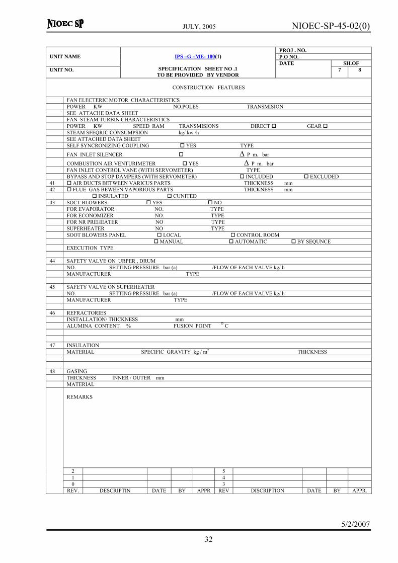
FAN ELECTERIC MOTOR CHARACTERISTICS POWER KW NO.POLES TRANSMISION SEE ATTACHE DATA SHEET FAN STEAM TURBIN CHARACTERISTICS POWER KW SPEED RAM TRANSMISIONS DIRECT GEAR STEAM SFEQRIC CONSUMPSION kg/ kw /h SEE ATTACHED DATA SHEET SELF SYNCRONIZING COUPLING YES TYPE FAN INLET SILENCER Δ P m. bar COMBUSTION AIR VENTURIMETER YES Δ P m. bar FAN INLET CONTROL VANE (WITH SERVOMETER) TYPE BYPASS AND STOP DAMPERS (WITH SERVOMETER) INCLUDED EXCLUDED 41 AIR DUCTS BETWEEN VARICUS PARTS THICKNESS mm 42 FLUE GAS BEWEEN VAPORIOUS PARTS THICKNESS mm INSULATED CUNITED 43 SOCT BLOWERS YES NO FOR EVAPORATOR NO. TYPE FOR ECONOMIZER NO. TYPE FOR NR PREHEATER NO TYPE SUPERHEATER NO TYPE SOOT BLOWERS PANEL LOCAL CONTROL ROOM MANUAL AUTOMATIC BY SEQUNCE EXECUTION TYPE 44 SAFETY VALVE ON URPER , DRUM NO. SETTING PRESSURE bar (a) /FLOW OF EACH VALVE kg/ h MANUFACTURER TYPE 45 SAFETY VALVE ON SUPERHEATER NO. SETTING PRESSURE bar (a) /FLOW OF EACH VALVE kg/ h MANUFACTURER TYPE 46 REFRACTORIES INSTALLATION/ THICKNESS mm ALUMINA CONTENT % FUSION POINT C o 47 INSULATION MATERIAL SPECIFIC GRAVITY kg / m2 THICKNESS 48 GASING THICKNESS INNER / OUTER mm MATERIAL
REMARKS
2 5 1 4 0 3
REV. DESCRIPTIN DATE BY APPR REV DISCRIPTION DATE BY APPR.

JULY, 2005 NIOEC-SP-45-02(0)
5/2/2007
33
PROJ . NO. P.O NO.
UNIT NAME
SH.OF UNIT NO.
IPS –G –ME- 180(1)
SPECIFICATION SHEET NO .1
TO BE PROVIDED BY VENDOR
DATE 8 8
CONSTRUCTION FEATURES
56 STACK MATERIAL SELF SUPPORTING CONCRETE INCLUDED EXCLUDED INTERNALLY GUNTED EXT.INSULATION FOR PERSONANEL PROTECTION EXTERNAL ANTIRUST PAINTING EXTERNAL LADDER WIND LOAD / SPEED bar/kg/h FLATFORMS FOR EXT. LADDER THICK/DIAMETER BASE mm TOF mm HEIGHT CORROSION ALLOWANCE mm. NO. FOR BOILER COMMON TO THE BOILERS STACK DAMPERS YES NO TYPE 57 VALVES LEVELS AND LOCAL INSTRUMENTATION VALVES ON PRESSURE PARTS SINGLE DOUBLE FEED WATER VALVES GATE CHECK CONTINUOS BLOW DOWN VALVES MANUAL MOTOR CHECK VALVE ON STEAM OUTLET START – UP BLOW OFF VALVES DOUELES MOTOR DRAIN AND VENT VALVES SINGLE DOUBLES VALVES FOR INSTR. ON PRESS PARTS DOUBLES SINGLE FUEL VALVES AS PER SPEC SILENCES ON STEAM LINE TO ATM YES NO FLOW RATE NOISE LEVEL 58 STEAM DRUM LEVEL INDICATORS NO TYPE ILLUNATED YES NO ELEC FEEDING 59 RENOTE LEVEL INDICATOR YES NO 60 SAMPLE COOLERS NO TYPE BOILER WATER SATURATED STEAM SUPERHEATED STEAM 51 BOILER DIMENSIONS AND WEIGHT TOTAL LENGTH mm TOTAL MOTH mm Total height mm MAX. DIMENSIONS AND WEIGHTS FOR TRANSPORT. Kg x x mm Dpuns weight kg LOWER UPPER EVAPORATOR TUBES WEIGHT kg ECONOMIZER kg SUPERHEATER kg STEEL STRUCTURE WEIGHT kg STACK WEIGHT kg DUCT WORK WEIGHT kg FIRING EQUIPMENT kg AUAL PIPING WEIGHT kg VALVES WEIGHT kg REFRACT WEIGHT kg INSULATION WEIGHT kg STEAM AIR HEATER WEIGHT kg AIR HEATER WEIGHT kg TAN WEIGHT kg TURBINE WEIGHT kg MOTOR WEIGHT kg
TOTAL WEIGHT OF SUPLY kg
REMARKS
2 5 1 4 0 3
REV. DESCRIPTIN DATE BY APPR REV DISCRIPTION DATE BY APPR.