Embed Size (px)
Citation preview

OFFSHORE STANDARD
DNVGL-OS-C301 Edition July 2015
Stability and watertight integrity
DNV GL AS
The electronic pdf version of this document found through http://www.dnvgl.com is the officially binding version. The documents are available free of charge in PDF format.
FOREWORD
DNV GL offshore standards contain technical requirements, principles and acceptance criteria related toclassification of offshore units.© DNV GL AS July 2015
Any comments may be sent by e-mail to [email protected]
This service document has been prepared based on available knowledge, technology and/or information at the time of issuance of this document. The use of thisdocument by others than DNV GL is at the user's sole risk. DNV GL does not accept any liability or responsibility for loss or damages resulting from any use ofthis document.
C
hang
es –
cur
rent
CHANGES – CURRENTGeneralThis document supersedes DNV-OS-C301, July 2014.
Text affected by the main changes in this edition is highlighted in red colour. However, if the changes
On 12 September 2013, DNV and GL merged to form DNV GL Group. On 25 November 2013 Det NorskeVeritas AS became the 100% shareholder of Germanischer Lloyd SE, the parent company of the GL Group,and on 27 November 2013 Det Norske Veritas AS, company registration number 945 748 931, changed itsname to DNV GL AS. For further information, see www.dnvgl.com. Any reference in this document to “DetNorske Veritas AS”, “Det Norske Veritas”, “DNV”, “GL”, “Germanischer Lloyd SE”, “GL Group” or any otherlegal entity name or trading name presently owned by the DNV GL Group shall therefore also be considereda reference to “DNV GL AS”.
involve a whole chapter, section or sub-section, normally only the title will be in red colour.
Main changes July 2015• GeneralThe revision of this document is part of the DNV GL merger, updating the previous DNV standard into a DNV GL format including updated nomenclature and document reference numbering, e.g.:
— Main class identification 1A1 becomes 1A.— DNV replaced by DNV GL.— DNV-RP-A201 to DNVGL-CG-0168. A complete listing with updated reference numbers can be found on
DNV GL's homepage on internet.
To complete your understanding, observe that the entire DNV GL update process will be implemented sequentially. Hence, for some of the references, still the legacy DNV documents apply and are explicitly indicated as such, e.g.: Rules for Ships has become DNV Rules for Ships.
In addition to the above stated main changes, editorial corrections may have been made.
Editorial corrections
Offshore standard, DNVGL-OS-C301 – Edition July 2015 Page 3Stability and watertight integrity
DNV GL AS
C
onte
nts
CONTENTSCHANGES – CURRENT ................................................................................................. 3
CH. 1 INTRODUCTION ......................................................... 7Sec.1 Introduction.................................................................................................. 7
1 General .....................................................................................................71.1 Introduction.......................................................................................71.2 Objectives .........................................................................................7
2 Normative references ...............................................................................72.1 General .............................................................................................72.2 Reference documents..........................................................................8
3 Informative references .............................................................................83.1 General .............................................................................................8
4 Definitions ...............................................................................................84.1 Verbal forms ......................................................................................84.2 Definitions .........................................................................................94.3 Abbreviations and symbols ................................................................10
5 Documentation .......................................................................................115.1 General ...........................................................................................11
CH. 2 TECHNICAL PROVISIONS ......................................... 12Sec.1 Stability....................................................................................................... 12
1 General ...................................................................................................121.1 Scope .............................................................................................12
2 Determination of wind forces .................................................................122.1 Heeling moment curves .....................................................................12
3 Determination of lightweight..................................................................143.1 Inclining test....................................................................................14
4 Intact stability requirements ..................................................................144.1 General ...........................................................................................144.2 Ship shaped units or installations........................................................154.3 Column stabilised units......................................................................164.4 Self elevating units or installations ......................................................164.5 Deep draught floating installations ......................................................164.6 Cylindrical surface units.....................................................................16
5 Damage stability requirements...............................................................175.1 General ...........................................................................................175.2 Ship shaped units or installations........................................................175.3 Self elevating units or installations ......................................................185.4 Column stabilised units or installations and cylindrical surface units.........185.5 Deep draught floating installations ......................................................195.6 Extent of damage – ship shaped, cylindrical and self-elevating units or
installations .....................................................................................205.7 Extent of damage – column stabilised units and deep draught floating
installations .....................................................................................205.8 Chain lockers ...................................................................................205.9 Machinery and machinery space openings ............................................215.10 Load line and draught marks..............................................................215.11 Extent of watertight and weathertight closing of external openings..........21
Offshore standard, DNVGL-OS-C301 – Edition July 2015 Page 4Stability and watertight integrity
DNV GL AS
C
onte
nts
5.12 Internal watertight integrity and subdivision.........................................215.13 Loading computers ...........................................................................21
Sec.2 Watertight integrity, freeboard and weathertight closing appliances.......... 221 General ...................................................................................................22
1.1 Application.......................................................................................22
2 Materials.................................................................................................222.1 Technical requirements .....................................................................222.2 Supplementary classification requirements...........................................22
3 Watertight integrity................................................................................223.1 General ...........................................................................................223.2 Internal openings .............................................................................233.3 External openings.............................................................................233.4 Strength of watertight doors and hatch covers......................................233.5 Frame and bulkhead interface ............................................................253.6 Operation and control of watertight doors and hatch covers....................26
4 Weathertight closing appliances.............................................................264.1 General ...........................................................................................264.2 Weathertight doors ...........................................................................274.3 Weathertight hatch coamings and covers .............................................274.4 Gaskets and closing devices ...............................................................284.5 Drainage arrangement ......................................................................284.6 Buckling check .................................................................................29
5 Freeboard ...............................................................................................295.1 General ...........................................................................................295.2 Self elevating units or installations ......................................................305.3 Column stabilised units or installations ................................................30
6 Ventilators and air pipes.........................................................................316.1 General ...........................................................................................31
7 Inlets, discharges and scuppers .............................................................317.1 Sea inlets and discharges in closed systems .........................................317.2 Discharges.......................................................................................327.3 Scuppers .........................................................................................32
8 Side scuttles and windows......................................................................338.1 General ...........................................................................................33
9 Testing of doors and hatch covers ..........................................................339.1 Pressure testing of watertight doors and hatch covers ...........................339.2 Hose testing of watertight and weathertight doors and hatch covers ........339.3 Function testing of watertight doors and hatch covers............................33
10 Closing arrangements for doors and hatch covers ..................................3410.1 Description of waterlines (beach lines).................................................3410.2 Description of location of openings......................................................3410.3 Operation, indication and locking ........................................................34
CH. 3 CERTIFICATION AND CLASSIFICATION.................... 37Sec.1 General ....................................................................................................... 37
1 Introduction ...........................................................................................371.1 Application.......................................................................................37
2 Design review.........................................................................................372.1 Documentation requirements .............................................................372.2 Specific classification requirements .....................................................37
Offshore standard, DNVGL-OS-C301 – Edition July 2015 Page 5Stability and watertight integrity
DNV GL AS

C
onte
nts
3 Certification of materials and components..............................................373.1 General ...........................................................................................373.2 Certification requirements under this standard......................................38
Offshore standard, DNVGL-OS-C301 – Edition July 2015 Page 6Stability and watertight integrity
DNV GL AS
Cha
pter
1
Sec
tion
1
CHAPTER 1 INTRODUCTIONSECTION 1 INTRODUCTION
1 General
1.1 Introduction1.1.1 This offshore standard provides principles, technical requirements and guidance related to stability, watertight integrity, freeboard and weathertight closing appliances for mobile offshore units and floating offshore installations.
The types of units and installations that are covered by this standard include:
— ship shaped units
— column stabilised units
— self elevating units
— deep draught units.
Guidance note:For novel designs, not recognised by the typical features of a known type of design, the stability requirements have to be considered separately and based on an evaluation of risks reflecting the unit's design, the intended operational aspects and the environmental conditions.
---e-n-d---of---g-u-i-d-a-n-c-e---n-o-t-e---
1.1.2 The standard has been written for general worldwide application. Governmental regulations may include requirements in excess of the provisions by this standard depending on the size, type, location and intended service of the offshore unit or installation.
1.2 ObjectivesThe objectives of this standard are to:
— provide an internationally acceptable standard of safety by defining minimum requirements for stability, watertight integrity, freeboard and weathertight closing appliances
— serve as a contractual reference document between suppliers and purchasers
— serve as a guideline for designers, suppliers, purchasers and regulators
— specify procedures and requirements for units or installations subject to DNV GL certification and classification.
2 Normative references
2.1 General2.1.1 The standards given in [2.2] include provisions which, through reference in the text, constitute provisions of this offshore standard. The latest issue of the references shall be used unless otherwise agreed.
2.1.2 Other recognised standards may be used provided it can be demonstrated that these meet or exceed the requirements of the standards given in [2.2].
2.1.3 Any deviations, exceptions and modifications to the design codes and standards shall be documented and agreed between the contractor, purchaser and verifier, as applicable.
Offshore standard, DNVGL-OS-C301 – Edition July 2015 Page 7Stability and watertight integrity
DNV GL AS
Cha
pter
1
Sec
tion
1
2.2 Reference documents2.2.1 Applicable DNV GL and DNV documents are given in Table 1.2.2.2 Other reference documents are given in Table 2.
3 Informative references
3.1 General3.1.1 Informative references are not considered mandatory in the application of this offshore standard, but may be applied or used for background information.
3.1.2 Informative references are given in Table 3.
4 Definitions
4.1 Verbal forms
Table 1 DNV GL and DNV reference documents
Reference TitleDNVGL-OS-B101 Metallic materialsDNVGL-OS-C101 Design of offshore steel structures, general - LRFD methodDNVGL-OS-C201 Structural design of offshore units - WSD methodDNVGL-OS-D101 Marine and machinery systems and equipmentDNV Rules for ships DNV Rules for Classification of ShipsDNVGL-CG-0168 Plan approval documentation types – definitionsDNV-RP-C205 Environmental Conditions and Environmental LoadsDNV Classification Notes 20.1 Stability Documentation for Approval
Table 2 Normative references
Reference TitleICLL 1966 International Convention on Load Lines, 1966, amended by Protocol 1988IMO MODU Code, 2009 Code for the Construction and Equipment of Mobile Offshore Drilling Units, 2009
Table 3 Informative references
Reference TitleISO 1751 Shipbuilding and marine structures - Ships’ side scuttlesISO 3903 Shipbuilding and marine structures - Ships’ ordinary rectangular windowsISO 1095 Shipbuilding and marine structures - Toughened safety glass panes for side scuttlesISO 614 Shipbuilding and marine structures - Toughened safety glass panes for rectangular
windows and side scuttles - Punch method of non-destructive testingSOLAS 1974 The International Convention for the Safety of Life at Sea, 1974, as amended
Table 4 Definitions
Term Definitionshall verbal form used to indicate requirements strictly to be followed in order to conform to the documentshould verbal form used to indicate that among several possibilities one is recommended as particularly suitable, without
mentioning or excluding others, or that a certain course of action is preferred but not necessarily requiredmay verbal form used to indicate a course of action permissible within the limits of the document
Offshore standard, DNVGL-OS-C301 – Edition July 2015 Page 8Stability and watertight integrity
DNV GL AS
Cha
pter
1
Sec
tion
1
4.2 DefinitionsTable 5 DefinitionsTerm Definitioncolumn stabilised unit a unit with the main deck connected to the underwater hull or footings by columnsdamage penetration zone defined as 1.5 m from the outer skin
The damage penetration zone is limited to exposed portions only.damage waterline the final equilibrium waterline, including the wind heeling moment, after a damagedownflooding any flooding of the interior of any part of the buoyant structure of a unit through openings
which cannot be closed watertight or weathertight, as appropriate, in order to meet the intact or damage stability criteria, or which are required for operational reasons to be left open
dynamic angle the angle of heel where the area requirement according to the stability requirements of Ch.2 Sec.1 is achieved
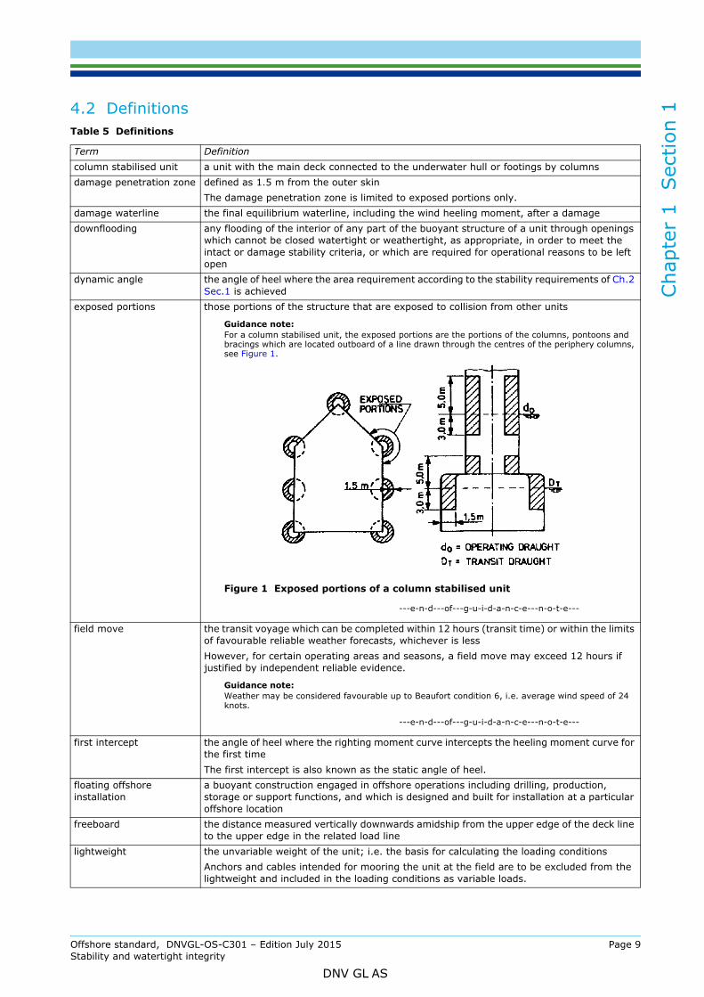
exposed portions those portions of the structure that are exposed to collision from other units
Guidance note:For a column stabilised unit, the exposed portions are the portions of the columns, pontoons and bracings which are located outboard of a line drawn through the centres of the periphery columns, see Figure 1.
Figure 1 Exposed portions of a column stabilised unit
---e-n-d---of---g-u-i-d-a-n-c-e---n-o-t-e---
field move the transit voyage which can be completed within 12 hours (transit time) or within the limits of favourable reliable weather forecasts, whichever is less However, for certain operating areas and seasons, a field move may exceed 12 hours if justified by independent reliable evidence.
Guidance note:Weather may be considered favourable up to Beaufort condition 6, i.e. average wind speed of 24 knots.
---e-n-d---of---g-u-i-d-a-n-c-e---n-o-t-e---
first intercept the angle of heel where the righting moment curve intercepts the heeling moment curve for the first time The first intercept is also known as the static angle of heel.
floating offshore installation
a buoyant construction engaged in offshore operations including drilling, production, storage or support functions, and which is designed and built for installation at a particular offshore location
freeboard the distance measured vertically downwards amidship from the upper edge of the deck line to the upper edge in the related load line
lightweight the unvariable weight of the unit; i.e. the basis for calculating the loading conditionsAnchors and cables intended for mooring the unit at the field are to be excluded from the lightweight and included in the loading conditions as variable loads.
Offshore standard, DNVGL-OS-C301 – Edition July 2015 Page 9Stability and watertight integrity
DNV GL AS

Cha
pter
1
Sec
tion
1
4.3 Abbreviations and symbolsAbbreviations used are given in Table 6.
maximum allowable vertical centre of gravity
the maximum vertical centre of gravity (VCG) which complies with both intact and damage stability requirements at a given draught and service mode All loading conditions are to have a VCG below the maximum allowable value for the given draught and service mode. The free surface effect of each slack tank should be calculated about the axis at which the moment of inertia is the greatest.
mobile offshore unit a buoyant construction engaged in offshore operations including drilling, production, storage or support functions, not intended for service at one particular offshore site and which can be relocated without major dismantling or modification
offshore installation a collective term to cover any construction, buoyant or non-buoyant, designed and built for installation at a particular offshore location
position 1 and 2 in accordance with Regulation 13 of the International Convention on Load Line 1966 (ILLC 1966), adapted to mobile offshore units
safe draught a draught which can be accepted under loading condition corresponding to damaged condition with respect to strength, and the requirement for minimum airgap is fulfilled
second intercept the angle of heel where the righting moment curve intercepts the heeling moment curve for the second time
self elevating unit a unit with movable legs capable of raising its hull above the surface of the seaservice modes — operation condition, i.e. normal working condition
— temporary conditions, i.e. transient conditions during change of draught to reach another service mode or installation mode
— survival condition, i.e. in case of severe storms— transit condition.
ship shaped unit a unit with a ship or barge type displacement hull of single or multiple hull construction intended for operation in the floating condition
variable load the load that varies with the operation of the unit such as deck cargo, fuel, lubricating oil, ballast water, fresh water, feedwater in tanks, consumable stores and crew and their effects
watertight capable of preventing the passage of water through the structure under a head of water for which the surrounding structure is designed
weathertight water will not penetrate into the unit in any sea conditions
Table 6 Abbreviations
Abbreviation Full textCG class guidelineCIBS classification information breakdown structureILLC International Convention on Load LinesIMO International Maritime OrganizationISO International Organisation for StandardisationLRFD load resistance factor designMODU mobile offshore drilling unitOS offshore standardRP recommended practiceVCG vertical centre of gravityWSD working stress design
Table 5 Definitions (Continued)
Term Definition
Offshore standard, DNVGL-OS-C301 – Edition July 2015 Page 10Stability and watertight integrity
DNV GL AS

Cha
pter
1
Sec
tion
1
5 Documentation5.1 General5.1.1 The documentation given in Table 7 is required to be produced to document aspects covered by this standard:
5.1.2 For general requirements to documentation, see DNVGL-CG-0168 Sec.1.
5.1.3 For a full definition of the documentation types, see DNVGL-CG-0168 Sec.2 and DNV Classification Note No. 20.1.
5.1.4 For documentation requirements related to certification and classification, see Ch.3.
Table 7 Documentation requirements
Object Documentation type Additional description For approval (AP) or For information (FI)
Stability
B010 – Lines plan or offset tables FI
B020 – External watertight integrity plan or freeboard plan
Subject to approval for Column-stabilised and self-elevating units where beach lines according to Ch.2 Sec.2 [10.1] must be included.
AP/FI
B030 – Internal watertight integrity plan FI
B040 – Stability analysis Not applicable for Ship-shaped units. See also definition of B050 for more details. AP
B050 – Preliminary stability manual Applicable for Ship-shaped units APB070 – Preliminary damage stability calculation
Applicable for Ship-shaped units. See also definition of B050 for more details. AP
B100 – Inclining test procedure APB110 – Inclining test report AP
B120 – Final stability manual The final stability manual may be included in the operation manual. AP
B130 – Final damage stability calculation
Applicable for Ship-shaped units AP
B200 – Freeboard plan AP
Offshore standard, DNVGL-OS-C301 – Edition July 2015 Page 11Stability and watertight integrity
DNV GL AS

Cha
pter
2
Sec
tion
1
CHAPTER 2 TECHNICAL PROVISIONSSECTION 1 STABILITY
1 General
1.1 Scope1.1.1 This section gives requirements related to the following design parameters of mobile offshore units and floating offshore installations:
1) Buoyancy and floatability.2) Wind exposed portions.3) Draught range at various modes of service.4) Watertight and weathertight closing of external openings.5) Internal watertight integrity and watertight subdivision.6) Lightweight and loading conditions.
1.1.2 The combination of the design parameters under [1.1.1] items 1 to 5 will determine the maximum allowable vertical centre of gravity (VCG) of the unit or installation at the applicable service draughts and modes.
1.1.3 The loading of the unit or installation at various service draughts and modes shall be within the limits of maximum allowable VCG-curves.
1.1.4 In order to determine VCG of the actual loading conditions, the lightweight and its centre of gravity must be known. This shall be obtained by an inclining test carried out in accordance with [3].
1.1.5 The requirements of this section are based on the IMO MODU Code, 2009.
1.1.6 Deep draught floating installations (e.g. SPARs) are not directly covered by the IMO MODU Code. Criteria identical to those of a column stabilised unit or installations have been adopted.
2 Determination of wind forces
2.1 Heeling moment curves2.1.1 The curves of wind heeling moments shall be drawn for wind forces calculated by the following formula:
(See MODU Code 3.2.3)
2.1.2 Wind forces shall be considered from any direction relative to the unit and the value of the wind velocity shall be as follows:
— in general a minimum wind velocity of 36 m/s (70 knots) for offshore service shall be used for normal operating and transit conditions and a minimum wind velocity of 51.5 m/s (100 knots) shall be used for the severe storm conditions
F = the wind force (Newton)Cs = the shape coefficient depending on the shape of the structural member exposed to the wind (see Table
2)Ch = the height coefficient depending on the height above sea level of the structural member exposed to
wind (see Table 2)P = the air mass density (1.222 kg/m3)V = the wind velocity (metres per second)A = the projected area of all exposed surfaces in either the upright or the heeled condition (square metres)
F 0 .5 C s Ch P V2 A⋅ ⋅ ⋅ ⋅=
Offshore standard, DNVGL-OS-C301 – Edition July 2015 Page 12Stability and watertight integrity
DNV GL AS
Cha
pter
2
Sec
tion
1
— where a unit is to be limited in operation to sheltered locations (protected inland waters such as lakes, bays, swamps, rivers, etc.) consideration shall be given to a reduced wind velocity of not less than 25.8 m/s (50 knots) for normal operating conditions.(See MODU Code 3.2.4)
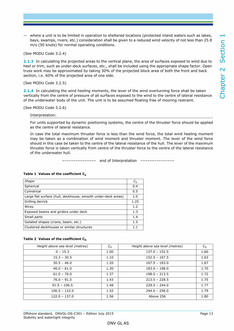
2.1.3 In calculating the projected areas to the vertical plane, the area of surfaces exposed to wind due to heel or trim, such as under-deck surfaces, etc., shall be included using the appropriate shape factor. Open truss work may be approximated by taking 30% of the projected block area of both the front and back section, i.e. 60% of the projected area of one side.
(See MODU Code 3.2.5)
2.1.4 In calculating the wind heeling moments, the lever of the wind overturning force shall be taken vertically from the centre of pressure of all surfaces exposed to the wind to the centre of lateral resistance of the underwater body of the unit. The unit is to be assumed floating free of mooring restraint.
(See MODU Code 3.2.6)
Interpretation:
For units supported by dynamic positioning systems, the centre of the thruster force should be appliedas the centre of lateral resistance.
In case the total maximum thruster force is less than the wind force, the total wind heeling momentmay be taken as a combination of wind moment and thruster moment. The lever of the wind forceshould in this case be taken to the centre of the lateral resistance of the hull. The lever of the maximumthruster force is taken vertically from centre of the thruster force to the centre of the lateral resistanceof the underwater hull.
––––––––––––––– end of Interpretation –––––––––––––––
Table 1 Values of the coefficient Cs
Shape Cs
Spherical 0.4Cylindrical 0.5Large flat surface (hull, deckhouse, smooth under-deck areas) 1.0Drilling derrick 1.25Wires 1.2Exposed beams and girders under deck 1.3Small parts 1.4Isolated shapes (crane, beam, etc.) 1.5Clustered deckhouses or similar structures 1.1
Table 2 Values of the coefficient Ch
Height above sea level (metres) Ch Height above sea level (metres) Ch
0 – 15.3 1.00 137.0 – 152.5 1.60
15.3 – 30.5 1.10 152.5 – 167.5 1.63
30.5 – 46.0 1.20 167.5 – 183.0 1.67
46.0 – 61.0 1.30 183.0 – 198.0 1.70
61.0 – 76.0 1.37 198.0 – 213.5 1.72
76.0 – 91.5 1.43 213.5 – 228.5 1.75
91.5 – 106.5 1.48 228.5 – 244.0 1.77
106.5 – 122.0 1.52 244.0 – 256.0 1.79
122.0 – 137.0 1.56 Above 256 1.80
Offshore standard, DNVGL-OS-C301 – Edition July 2015 Page 13Stability and watertight integrity
DNV GL AS
Cha
pter
2
Sec
tion
1
2.1.5 The wind heeling moment curve shall be calculated for a sufficient number of heel angles to define the curve. For ship-shaped hulls the curve may be assumed to vary as the cosine function of vessel heel.(See MODU Code 3.2.7)
2.1.6 Wind heeling moments derived from wind tunnel tests on a representative model of the unit may be considered as alternatives to the methods given in [2.1.1].
(See MODU Code 3.2.8)
3 Determination of lightweight
3.1 Inclining test3.1.1 An inclining test shall be required for the first unit of a design, when the unit is as near to completion as possible, to determine accurately the light ship data (weight and position of centre of gravity).
(See MODU Code 3.1.1)
Interpretation:
For self-elevating units, lightweight Centre of Gravity should be specified for each relevant position oflegs.
––––––––––––––– end of Interpretation –––––––––––––––
3.1.2 For successive units which are identical by design, the light ship data of the first unit of the series may be accepted in lieu of an inclining test, provided the difference in light ship displacement or position of centre of gravity due to weight changes for minor differences in machinery, outfitting or equipment, confirmed by the results of a deadweight survey, are less than 1% of the values of the light ship displacement and principal horizontal dimensions as determined for the first series.
Such dispensation cannot be granted for column stabilised units.
(See MODU Code 3.1.2)
4 Intact stability requirements
4.1 General4.1.1 Each unit shall be capable of attaining a severe storm condition in a period of time consistent with the meteorological conditions. The procedures recommended and the approximate length of time required, considering both operating conditions and transit conditions, shall be contained in the stability manual. It shall be possible to achieve the severe storm condition without the removal or relocation of solid consumables or other variable load. However, it may be acceptable loading a unit past the point at which solid consumables would have to be removed or relocated to go to severe storm condition under the following conditions, provided the allowable VCG requirement is not exceeded:
1) In a geographic location where weather conditions annually or seasonally do not become sufficientlysevere to require a unit to go to severe storm condition, or
2) Where a unit is required to support extra deck load for a short period of time that falls well within aperiod for which the weather forecast is favourable.
The geographic locations, weather conditions and loading conditions in which this is permitted shall be identified in the stability manual.
(See MODU Code 3.3.2)
Interpretation:
For column stabilised units where a change in draft is necessary to reach the severe storm condition;ballasting and de-ballasting curves should be worked out. Reference is made to DNV Classification Note
Offshore standard, DNVGL-OS-C301 – Edition July 2015 Page 14Stability and watertight integrity
DNV GL AS

Cha
pter
2
Sec
tion
1
No. 20.1, May 2011 Limit curves or maximum allowable VCG-curves, column-stabilised units foradditional information.––––––––––––––– end of Interpretation –––––––––––––––
4.1.2 Alternative stability criteria may be acceptable, provided an equivalent level of safety is maintained and if it can demonstrate to afford adequate positive initial stability. In determining the acceptability of such criteria, the following will be considered and taken into account as appropriate:
1) Environmental conditions representing realistic winds (including gusts) and waves appropriate forworld-wide service in various modes of operation;
2) Dynamic response of a unit. Analysis shall include the results of wind tunnel tests, wave tank modeltests, and non-linear simulation, where appropriate. Any wind and wave spectra used shall coversufficient frequency ranges to ensure that critical motion responses are obtained;
3) Potential for flooding taking into account dynamic responses in a seaway;4) Susceptibility to capsizing considering the unit's restoration energy and the static inclination due to the
mean wind speed and the maximum dynamic response;5) An adequate safety margin to account for uncertainties.
(See MODU Code 3.3.3)
4.2 Ship shaped units or installations4.2.1 For units or installations having a ship shaped hull form, the intact stability requirements of the DNV Rules for ships, Pt.3 Ch.3 Sec.9 D101, shall be met.
(See IS Code)
4.2.2 The area under the righting moment curve to the second intercept or downflooding angle, whichever is less, shall be not less than 40% in excess of the area under the wind heeling moment curve to the same limiting angle. See Figure 1.
(See MODU Code 3.3.1.1)
4.2.3 The righting moment curve shall be positive over the entire range of angles from upright to the second intercept.
(See MODU Code 3.3.1.3)
Figure 1 Righting moment and heeling moment curves
Guidance note 1:In this context, the downflooding angle represents the angle of heel at which the first opening that cannot be closed watertight or weathertight gets immersed (so-called unprotected opening).
---e-n-d---of---g-u-i-d-a-n-c-e---n-o-t-e---
Offshore standard, DNVGL-OS-C301 – Edition July 2015 Page 15Stability and watertight integrity
DNV GL AS

Cha
pter
2
Sec
tion
1
Guidance note 2:For units storing oil, the stability requirements of MARPOL should be considered, see IMO Res. MEPC 139 & 142.---e-n-d---of---g-u-i-d-a-n-c-e---n-o-t-e---
4.3 Column stabilised units4.3.1 The area under the righting moment curve to the angle of downflooding shall be not less than 30% in excess of the area under the wind heeling moment curve to the same limiting angle.
(See MODU Code 3.3.1.2)
4.3.2 The righting moment curve shall be positive over the entire range of angles from upright to the second intercept.
(See MODU Code 3.3.1.3)
4.3.3 During temporary conditions the metacentric height (GM) shall be at least 0.3 m.
4.4 Self elevating units or installations4.4.1 The area under the righting moment curve to the second intercept or downflooding angle, whichever is less, shall be not less than 40% in excess of the area under the wind heeling moment curve to the same limiting angle.
(See MODU Code 3.3.1.1)
4.4.2 The righting moment curve shall be positive over the entire range of angles from upright to the second intercept.
(See MODU Code 3.3.1.3)
4.5 Deep draught floating installations4.5.1 The area under the righting moment curve to the second intercept or downflooding angle, whichever is less, shall be not less than 30% in excess of the area under the wind heeling moment curve to the same limiting angle.
(See MODU Code 3.3.1.2)
4.5.2 The righting moment curve shall be positive over the entire range of angles from upright to the second intercept.
(See MODU Code 3.3.1.3)
4.5.3 Current is to be included in calculation of overturning moment. Guidance on calculation of current can be found in DNV-RP-C205.
4.5.4 Intact inclination angle is limited to 6° and 12° for normal operating conditions and survival conditions, respectively.
4.6 Cylindrical surface units4.6.1 The area under the righting moment curve to the angle of downflooding shall be not less than 30% in excess of the area under the wind heeling moment curve to the same limiting angle.
(See MODU Code 3.3.1.2)
4.6.2 The righting moment curve shall be positive over the entire range of angles from upright to the second intercept.
(See MODU Code 3.3.1.3)
Guidance note:For units storing oil, the stability requirements of MARPOL may be applicable, see IMO Res. MEPC 139 & 142.
---e-n-d---of---g-u-i-d-a-n-c-e---n-o-t-e---
Offshore standard, DNVGL-OS-C301 – Edition July 2015 Page 16Stability and watertight integrity
DNV GL AS
Cha
pter
2
Sec
tion
1
5 Damage stability requirements5.1 General5.1.1 It shall be demonstrated that the unit or installation complies with the requirements of [5.2] to [5.5] by calculations, which take into consideration the proportions and design characteristics of the unit or installation and the arrangements and configuration of the damaged compartments. In making these calculations it shall be assumed that the unit or installation is in the worst anticipated service condition as regards stability and is floating free of mooring restraints.
(See MODU Code 3.4.5)
5.1.2 The ability to reduce angles of inclination by pumping out or ballasting compartments or application of mooring forces, etc., shall not be considered as justifying any relaxation of the requirements.
(See MODU Code 3.4.6)
5.1.3 The following permeability factors shall be assumed in the calculations:
Store rooms: 0.60Engine room: 0.85Tanks, void spaces etc: 0.95
(See SOLAS II-1 7-3)
Guidance note:Other permeabilities may be accepted if documented by calculations.
---e-n-d---of---g-u-i-d-a-n-c-e---n-o-t-e---
5.1.4 Alternative subdivision and damage stability criteria may be acceptable provided an equivalent level of safety is maintained. The alternative stability criteria, shall consider at least the following and take into account:
1) Extent of damage as set out in [5.6] and [5.7];
2) On column stabilised units, the flooding of any compartment as set out in [5.4.2];
3) The provision of an adequate margin against capsizing.
(See MODU Code 3.4.7)
5.2 Ship shaped units or installations5.2.1 The unit shall have sufficient freeboard and be subdivided by means of watertight decks and bulkheads to provide sufficient buoyancy and stability to withstand in general the flooding of any one compartment in any operating or transit condition consistent with the damage assumptions set out in [5.6].
(See MODU Code 3.4.1)
5.2.2 The unit shall have sufficient reserve stability in a damaged condition to withstand the wind heeling moment based on a wind velocity of 25.8 m/s (50 knots) superimposed from any direction. In this condition the final waterline, after flooding, shall be below the lower edge of any downflooding opening.
Guidance note 1:In this context, the downflooding opening is an opening that cannot be closed watertight (i.e. includes both weathertight and unprotected openings).
---e-n-d---of---g-u-i-d-a-n-c-e---n-o-t-e---
Guidance note 2:Additional requirements following different statutory certificates, if applicable, may come into force.
---e-n-d---of---g-u-i-d-a-n-c-e---n-o-t-e---
Offshore standard, DNVGL-OS-C301 – Edition July 2015 Page 17Stability and watertight integrity
DNV GL AS
Cha
pter
2
Sec
tion
1
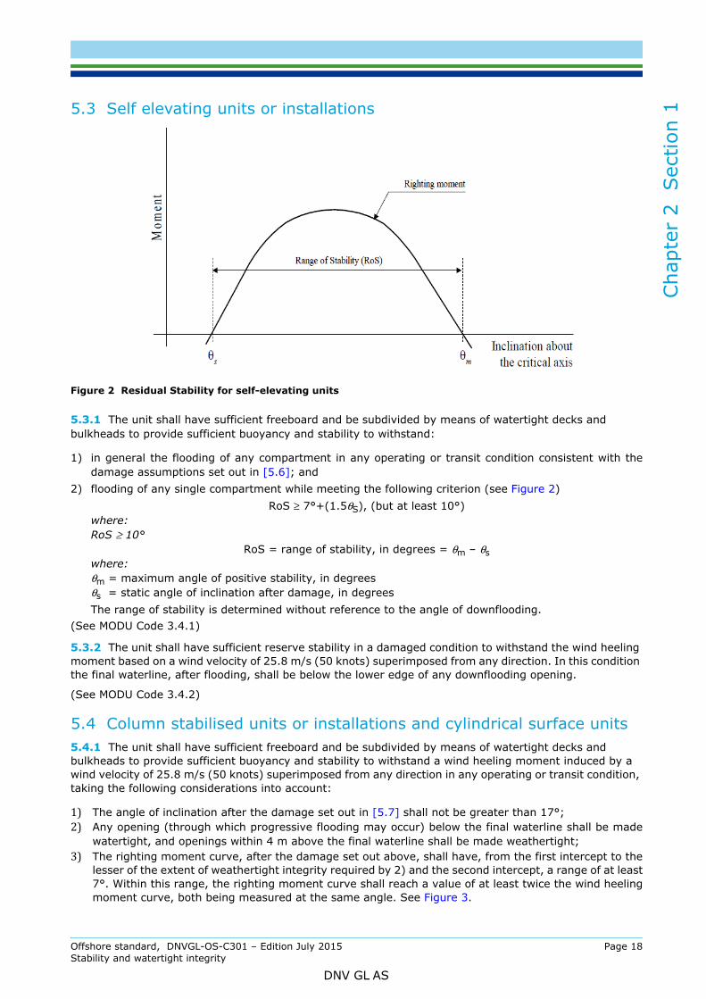
5.3 Self elevating units or installationsFigure 2 Residual Stability for self-elevating units
5.3.1 The unit shall have sufficient freeboard and be subdivided by means of watertight decks and bulkheads to provide sufficient buoyancy and stability to withstand:
1) in general the flooding of any compartment in any operating or transit condition consistent with thedamage assumptions set out in [5.6]; and
2) flooding of any single compartment while meeting the following criterion (see Figure 2)RoS ≥ 7°+(1.5θS), (but at least 10°)
where:RoS ≥ 10°
RoS = range of stability, in degrees = θm – θswhere:θm = maximum angle of positive stability, in degreesθs = static angle of inclination after damage, in degreesThe range of stability is determined without reference to the angle of downflooding.
(See MODU Code 3.4.1)
5.3.2 The unit shall have sufficient reserve stability in a damaged condition to withstand the wind heeling moment based on a wind velocity of 25.8 m/s (50 knots) superimposed from any direction. In this condition the final waterline, after flooding, shall be below the lower edge of any downflooding opening.
(See MODU Code 3.4.2)
5.4 Column stabilised units or installations and cylindrical surface units5.4.1 The unit shall have sufficient freeboard and be subdivided by means of watertight decks and bulkheads to provide sufficient buoyancy and stability to withstand a wind heeling moment induced by a wind velocity of 25.8 m/s (50 knots) superimposed from any direction in any operating or transit condition, taking the following considerations into account:1) The angle of inclination after the damage set out in [5.7] shall not be greater than 17°;2) Any opening (through which progressive flooding may occur) below the final waterline shall be made
watertight, and openings within 4 m above the final waterline shall be made weathertight;3) The righting moment curve, after the damage set out above, shall have, from the first intercept to thelesser of the extent of weathertight integrity required by 2) and the second intercept, a range of at least7°. Within this range, the righting moment curve shall reach a value of at least twice the wind heelingmoment curve, both being measured at the same angle. See Figure 3.
Offshore standard, DNVGL-OS-C301 – Edition July 2015 Page 18Stability and watertight integrity
DNV GL AS

Cha
pter
2
Sec
tion
1
Figure 3 Righting moment and wind heeling moment curves
(See MODU Code 3.4.3)
5.4.2 The unit shall provide sufficient buoyancy and stability in any operating or transit condition to withstand the flooding of any watertight compartment wholly or partially below the waterline in question, which is a pump-room, a room containing machinery with a salt water cooling system or a compartment adjacent to the sea, taking the following considerations into account:
1) The angle of inclination after flooding shall not be greater than 25°;
2) Any opening below the final waterline shall be made watertight;
3) A range of positive stability shall be provided, beyond the calculated angle of inclination in theseconditions, of at least 7°.
(See MODU Code 3.4.4)
Interpretation:
For the purpose of flooding and stability considerations “any watertight compartment” includes thosecompartments containing sea water piping systems.
––––––––––––––– end of Interpretation –––––––––––––––
5.5 Deep draught floating installationsThe installation shall have sufficient freeboard and be subdivided by means of watertight decks and bulkheads to provide sufficient buoyancy and stability to withstand a wind heeling moment induced by a wind velocity of 25.8 m/s (50 knots) superimposed from any direction in any operating or transit condition, taking the following considerations into account:
1) The angle of inclination after the damage set out in [5.7] shall not be greater than 17°;2) Any opening through which progressive flooding may occur below the final waterline shall be made
watertight, and openings within 4 m above the final waterline shall be made weathertight;3) The righting moment curve, after the damage set out above, shall have, from the first intercept to the
lesser of the extent of weathertight integrity required by [5.4.1] 2) and the second intercept, a rangeof at least 7°. Within this range, the righting moment curve shall reach a value of at least twice the windheeling moment curve, both being measured at the same angle. See Figure 3.
(See MODU Code 3.4.3)
Offshore standard, DNVGL-OS-C301 – Edition July 2015 Page 19Stability and watertight integrity
DNV GL AS
Cha
pter
2
Sec
tion
1
5.6 Extent of damage – ship shaped, cylindrical and self-elevating units or installationsIn assessing the damage stability of such units the following extent of damage is assumed to occur between effective watertight bulkheads:1) Horizontal penetration: 1.5 m. 2) Vertical extent: from the base line upwards without limit.
The distance between effective watertight bulkheads or their nearest stepped portions which are positioned within the assumed extent of horizontal penetration shall be not less than 3.0 m; where there is a lesser distance one or more of the adjacent bulkheads shall be disregarded.
Where damage of a lesser extent than the above results in a more severe condition, such lesser extent shall be assumed.
Where a mat is fitted for self elevating units the above extent of damage shall be applied to both the platform and the mat but not simultaneously, unless deemed necessary due to their close proximity to each other.
All piping, ventilation systems, trunks, etc., within the extent of damage shall be assumed damaged. Positive means of closure shall be provided at watertight boundaries to preclude the progressive flooding of other spaces which are intended to be intact.
(See MODU Code 3.5)
5.7 Extent of damage – column stabilised units and deep draught floating installationsIn assessing the damage stability of such units, the following extent of damage shall be assumed:
1) Only those columns, underwater hulls and braces on the periphery of the unit shall be assumed to bedamaged, and the damage shall be assumed in the exposed portions of the columns, underwater hullsand braces.
2) Columns and braces shall be assumed flooded by damage having a vertical extent of 3.0 m occurringat any level between 5.0 m above and 3.0 m below the draughts specified in the stability manual. Wherea watertight flat is located within this region, the damage shall be assumed to have occurred in bothcompartments above and below the watertight flat in question. Lesser distances above or below thedraughts may be applied upon consideration, taking into account the actual operating conditions.However, the required damage region shall extend at least 1.5 m above and below the draught specifiedin the operating manual.
3) No vertical bulkhead shall be assumed damaged, except where bulkheads are spaced closer than adistance of one eighth of the column perimeter at the draught under consideration, measured at theperiphery, in which case one or more of the bulkheads shall be disregarded.
4) Horizontal penetration of damage shall be assumed to be 1.5 m.5) Underwater hull or footings shall be assumed damaged when operating in a transit condition in the same
manner as indicated in 1), 2), 4) and either 3) or [5.6], having regard to their shape.6) All piping, ventilation systems, trunks, etc., within the extent of damage shall be assumed damaged.
Positive means of closure shall be provided at watertight boundaries to preclude the progressive floodingof other spaces that are intended to be intact.
7) All Deep Draught Units shall comply with the damage stability survival requirements in [5.5] assumingflooding of any single watertight compartment located at or below the waterline corresponding to themaximum draught.
(See MODU Code 3.5.10)
5.8 Chain lockers5.8.1 Chain lockers, which are not provided with weathertight closing appliances, shall be provided with level alarm or sounding and bilge arrangement or drainage system in accordance with DNVGL-OS-D101. In this case the chain pipes will be regarded as downflooding points.
(See MODU Code 3.6.8)
Offshore standard, DNVGL-OS-C301 – Edition July 2015 Page 20Stability and watertight integrity
DNV GL AS
Cha
pter
2
Sec
tion
1
5.8.2 When chain lockers without weathertight closing appliances are used as ballast tanks, downflooding through chain pipes can be disregarded at a given draught provided that chain lockers are:— equipped as ballast tanks according to DNVGL-OS-D101
— kept full at the given draught. This shall be stated in the stability manual.
Conditions during the cleaning of chain lockers shall be considered as temporary conditions.
5.9 Machinery and machinery space openingsOpenings necessary for continuous air supply for operation of machinery space and emergency generator room shall be located in a position where weathertight closing according to Ch.2 Sec.2 [10.1] and [10.2] is not required.
(See ICLL Annex I, Reg. 17)
5.10 Load line and draught marks5.10.1 The unit or installation shall have load line marks according to the maximum permissible draught in the afloat condition.
5.10.2 The load line marks will be assigned on the basis of compliance with the requirements of this section as well as other applicable requirements.
5.10.3 Draught marks shall be located in positions, which will ensure accurate determination of draughts, trim and heel and where they are clearly visible to personnel operating the unit or installation. The reference line shall be defined in the stability manual.
5.11 Extent of watertight and weathertight closing of external openings5.11.1 Watertight closing appliances are required for those external openings being submerged at least up to an angle of heel equal to the first intercept in intact or damage condition, whichever is greater.
5.11.2 Weathertight closing appliances are required for those external openings being submerged at least up to an angle of heel equal to the dynamic angle. This applies to any opening within 4.0 m above the final waterline as well.
Guidance note:See DNVGL-OSS-201 for additional requirements for units intended for the Norwegian shelf, see also Ch.2 Sec.2 [10.1] and [10.2].
---e-n-d---of---g-u-i-d-a-n-c-e---n-o-t-e---
5.12 Internal watertight integrity and subdivision5.12.1 The internal subdivision shall be adequate to enable the unit or installation to comply with the damage stability requirements of this section.
5.12.2 Ducts or piping, which may cause progressive flooding in case of damage, shall generally not be used in the damage penetration zone.
5.13 Loading computersLoading computers for stability calculation shall be considered as supplementary to the stability manual or the stability part of the operation manual.
Guidance note:See the applicable Rules for Mobile Offshore Units Ch.2 Sec.1 [6.1.2] and Rules for Self-elevating drilling units Pt. 3 Ch.2 Sec. 2 and DNV Rules for Ships Pt. 6 Ch.9 for information regarding approval of loading computers.
---e-n-d---of---g-u-i-d-a-n-c-e---n-o-t-e---
Offshore standard, DNVGL-OS-C301 – Edition July 2015 Page 21Stability and watertight integrity
DNV GL AS
Cha
pter
2
Sec
tion
2
SECTION 2 WATERTIGHT INTEGRITY, FREEBOARD AND WEATHERTIGHT CLOSING APPLIANCES1 General
1.1 Application1.1.1 This section provides requirements with regards to arrangement and design of watertight integrity and freeboard for self elevating and column stabilised units and installations.
1.1.2 Watertight integrity, freeboard plan and weathertight closing appliances for ship shaped units or installations shall comply with the DNV Rules for ships Pt.3 Ch.1, Ch.3 Sec.6 and Sec.9 with the following additional requirements:
a) Doors in unprotected fronts and sides shall be of steel. b) For doors located in exposed positions in sides and front bulkheads, the requirements to sill heights
apply one deck higher than given by the DNV Rules for ships Pt.3 Ch.3 Sec.6 B.
1.1.3 Piping and electrical systems for operation of watertight closing appliances shall be in accordance with relevant requirements given in DNVGL-OS-D101 unless otherwise specified in this section.
2 Materials
2.1 Technical requirements2.1.1 Materials for:
— rolled steel for structural applications and pressure vessels— steel tubes, pipes and fittings— steel forgings— steel castings— aluminium alloys
shall comply with the requirements given by DNVGL-OS-B101 unless otherwise stated in the relevant technical reference documents.
2.1.2 Stainless steel shall be with a maximum carbon content of 0.05%. The stainless steel material shall be of the white pickled and passivated condition.
2.1.3 Aluminium shall be of seawater resistant type.
2.2 Supplementary classification requirements2.2.1 Certification requirements for materials are given in DNVGL-OS-B101, Ch.3.
2.2.2 Rolled, forged or cast elements of steel and aluminium for structural application shall be supplied with DNV GL material certificates in compliance with the requirements given in DNVGL-OS-B101.
3 Watertight integrity
3.1 General3.1.1 The number of openings in watertight subdivisions shall be kept to a minimum compatible with the design and proper working of the unit or installation. Where penetrations of watertight decks and bulkheads are necessary for access, piping, ventilation, electrical cables etc., arrangements shall be made to maintain the watertight integrity of the enclosed compartments.
3.1.2 Locations of openings where watertight integrity is required, are illustrated in [9].
Offshore standard, DNVGL-OS-C301 – Edition July 2015 Page 22Stability and watertight integrity
DNV GL AS
Cha
pter
2
Sec
tion
2
3.1.3 The strength and arrangement of sliding doors and hatch covers and their frames as well as the capacity of the closing systems shall be sufficient to ensure efficient closing of doors and hatch covers when water with a head of 2.0 m is flowing through the opening, and at an inclination of 17° in any direction.3.2 Internal openings3.2.1 The means to ensure the watertight integrity of internal openings shall comply with the following:
a) Doors and hatch covers which are used during the operation of the unit while afloat shall be remotely controlled from the central ballast control station and shall also be operable locally from each side. Open/shut indicators shall be provided at the control station.
b) Doors or hatch covers in self-elevating units, or doors placed above the deepest load line draft in column-stabilized and surface units, which are normally closed while the unit is afloat may be of the quick acting type and shall be provided with an alarm system (e.g., light signals) showing personnel both locally and at the central ballast control station whether the doors or hatch covers in question are open or closed. A notice shall be affixed to each such door or hatch cover stating that it is not to be left open while the unit is afloat.
c) Remotely operated doors shall meet SOLAS regulation II-1/13-1.2.
Guidance note:Explanatory information on terms and definitions are provided in IACS UI SC156 “Doors in watertight bulkheads on passenger ships and cargo ships”.
---e-n-d---of---g-u-i-d-a-n-c-e---n-o-t-e---
3.2.2 The means to ensure the watertight integrity of internal openings which are intended only to provide access for inspection and are kept permanently closed during the operation of the unit, while afloat, shall have a notice affixed to each such closing appliance stating that it is to be kept closed while the unit is afloat; however, manholes fitted with close bolted covers need not be so marked.
3.2.3 Where valves are provided at watertight boundaries to maintain watertight integrity, these valves shall be capable of being operated from a control room. Valve position indicators shall be provided at the remote control station.
If the valves are remotely operated by means of mechanical devices, operation from a deck, which is above any final waterline after flooding will be accepted. Valve position indicators shall be provided at the remote control station.
3.3 External openings3.3.1 Where watertight integrity is dependent on external openings, which are used during the operation of the unit or installation while afloat, they shall comply with a), b) and c).
a) The lower edge of openings of air pipes (regardless of their closing appliances) shall be above the damage waterline.
b) The lower edge of ventilator openings, doors and hatch covers with manually operated means of weathertight closures shall be above damage waterline, unless [3.3.3] applies.
c) Openings such as manholes fitted with closely bolted covers, and side scuttles or windows of the non-opening type with inside hinged deadlights may be submerged.
3.3.2 The requirements of [3.3.1] b) apply where the watertight integrity is dependent on external openings, which are permanently closed during the operation of the unit or installation, while afloat.
3.3.3 External doors and hatch covers of limited size may be accepted between the damage waterline and freeboard deck provided they are watertight closeable locally and by remote operation of the closing appliances from the control room, with indicators showing whether the openings are closed or open.
3.4 Strength of watertight doors and hatch covers3.4.1 Watertight doors and hatch covers for internal and external openings shall be designed with a strength equivalent to or better than required for the watertightness of the structure in which they are positioned.
Offshore standard, DNVGL-OS-C301 – Edition July 2015 Page 23Stability and watertight integrity
DNV GL AS
Cha
pter
2
Sec
tion
2
3.4.2 Strength of watertight doors and hatches in general shall comply with structural requirements stated in DNVGL-OS-C101 Ch.2, Sec. 4 or DNVGL-OS-C201 Ch.2, Sec. 4 following the LRFD respectively the WSD design approach.3.4.3 Provided flooding is a possible mode of failure based upon the damage assumptions as given in Sec.1, for compartments on both sides of a watertight door or hatch cover, the watertight door or hatch cover shall be designed to withstand the design pressure from both sides.
3.4.4 The design pressure shall be taken as the waterhead corresponding to the vertical distance between the load point and the deepest waterline after damage.
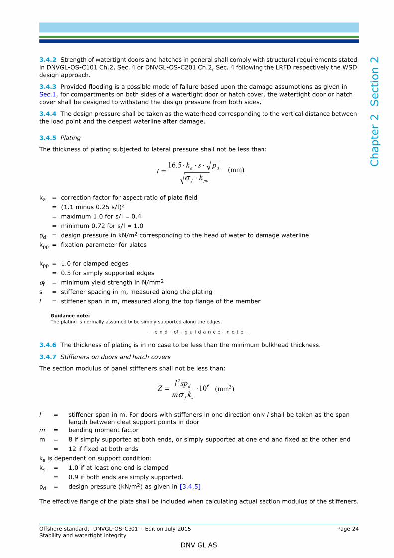
3.4.5 Plating
The thickness of plating subjected to lateral pressure shall not be less than:
Guidance note:The plating is normally assumed to be simply supported along the edges.
---e-n-d---of---g-u-i-d-a-n-c-e---n-o-t-e---
3.4.6 The thickness of plating is in no case to be less than the minimum bulkhead thickness.
3.4.7 Stiffeners on doors and hatch covers
The section modulus of panel stiffeners shall not be less than:
The effective flange of the plate shall be included when calculating actual section modulus of the stiffeners.
ka = correction factor for aspect ratio of plate field= (1.1 minus 0.25 s/l)2
= maximum 1.0 for s/l = 0.4= minimum 0.72 for s/l = 1.0
pd = design pressure in kN/m2 corresponding to the head of water to damage waterlinekpp = fixation parameter for plates
kpp = 1.0 for clamped edges= 0.5 for simply supported edges
σf = minimum yield strength in N/mm2
s = stiffener spacing in m, measured along the platingl = stiffener span in m, measured along the top flange of the member
l = stiffener span in m. For doors with stiffeners in one direction only l shall be taken as the span length between cleat support points in door
m = bending moment factorm = 8 if simply supported at both ends, or simply supported at one end and fixed at the other end
= 12 if fixed at both endsks is dependent on support condition:ks = 1.0 if at least one end is clamped
= 0.9 if both ends are simply supported.pd = design pressure (kN/m2) as given in [3.4.5]
ppf
da
kpsk
t⋅
⋅⋅⋅=
σ5.16 (mm)
62
10⋅=sf
d
kmsplZ
σ(mm3)
Offshore standard, DNVGL-OS-C301 – Edition July 2015 Page 24Stability and watertight integrity
DNV GL AS
Cha
pter
2
Sec
tion
2
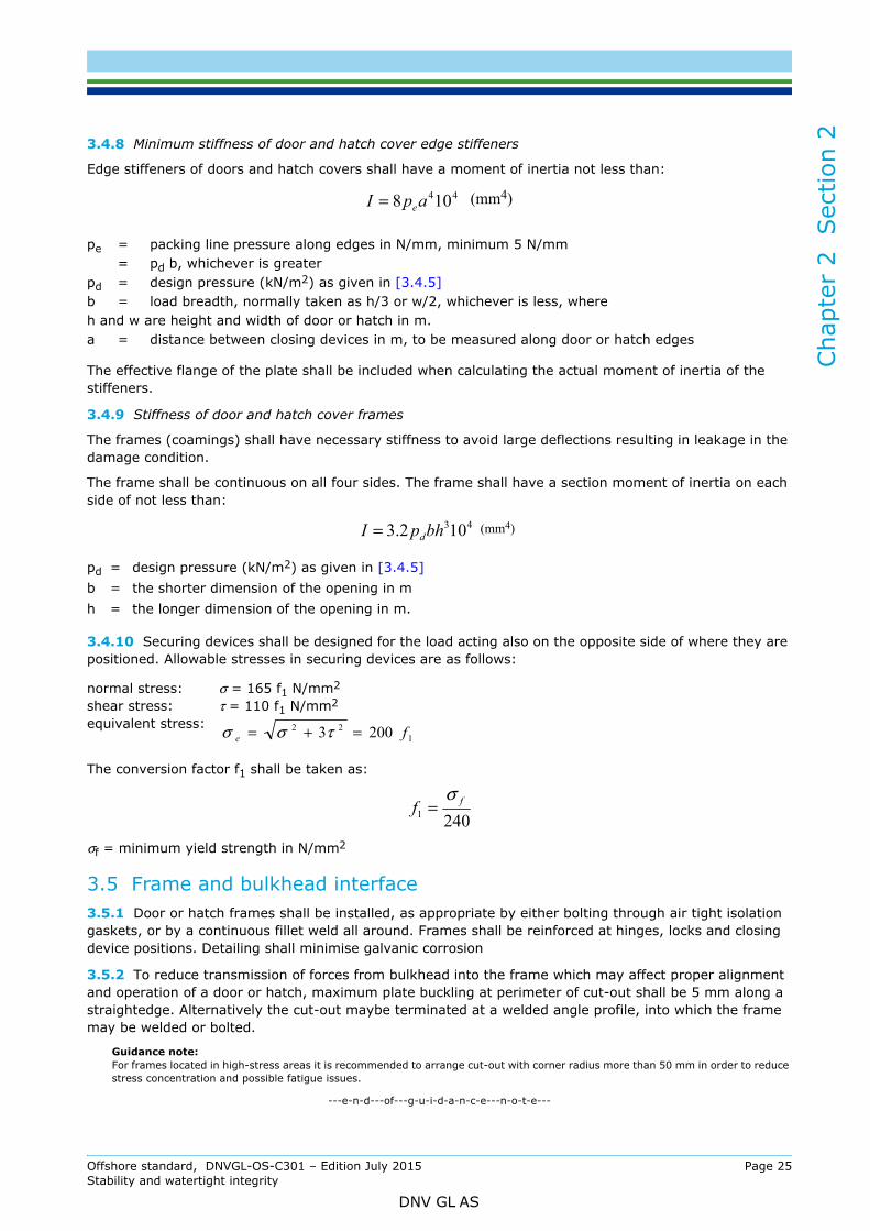
3.4.8 Minimum stiffness of door and hatch cover edge stiffenersEdge stiffeners of doors and hatch covers shall have a moment of inertia not less than:
The effective flange of the plate shall be included when calculating the actual moment of inertia of the stiffeners.
3.4.9 Stiffness of door and hatch cover frames
The frames (coamings) shall have necessary stiffness to avoid large deflections resulting in leakage in the damage condition.
The frame shall be continuous on all four sides. The frame shall have a section moment of inertia on each side of not less than:
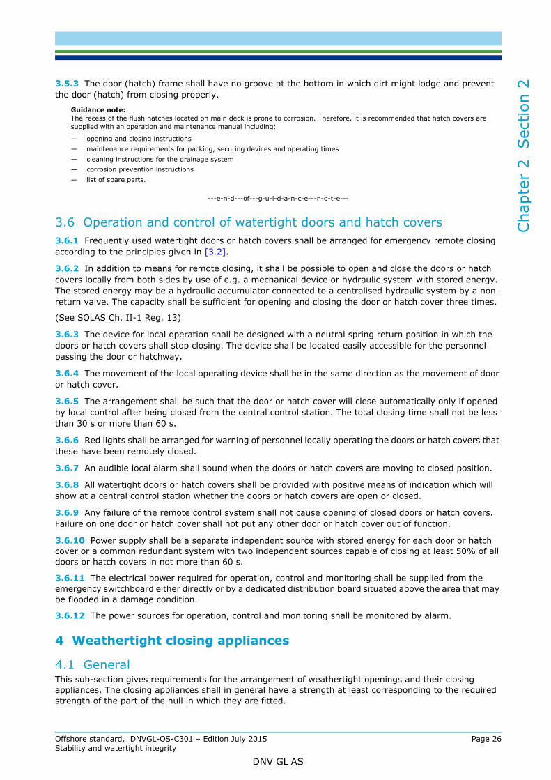
3.4.10 Securing devices shall be designed for the load acting also on the opposite side of where they are positioned. Allowable stresses in securing devices are as follows:
The conversion factor f1 shall be taken as:
σf = minimum yield strength in N/mm2
3.5 Frame and bulkhead interface3.5.1 Door or hatch frames shall be installed, as appropriate by either bolting through air tight isolation gaskets, or by a continuous fillet weld all around. Frames shall be reinforced at hinges, locks and closing device positions. Detailing shall minimise galvanic corrosion
3.5.2 To reduce transmission of forces from bulkhead into the frame which may affect proper alignment and operation of a door or hatch, maximum plate buckling at perimeter of cut-out shall be 5 mm along a straightedge. Alternatively the cut-out maybe terminated at a welded angle profile, into which the frame may be welded or bolted.
Guidance note:For frames located in high-stress areas it is recommended to arrange cut-out with corner radius more than 50 mm in order to reduce stress concentration and possible fatigue issues.
---e-n-d---of---g-u-i-d-a-n-c-e---n-o-t-e---
pe = packing line pressure along edges in N/mm, minimum 5 N/mm= pd b, whichever is greater
pd = design pressure (kN/m2) as given in [3.4.5]b = load breadth, normally taken as h/3 or w/2, whichever is less, whereh and w are height and width of door or hatch in m.a = distance between closing devices in m, to be measured along door or hatch edges
pd = design pressure (kN/m2) as given in [3.4.5] b = the shorter dimension of the opening in mh = the longer dimension of the opening in m.
normal stress: σ = 165 f1 N/mm2 shear stress: τ = 110 f1 N/mm2 equivalent stress:
44108 apI e= (mm4)
43102.3 bhpI d= (mm4)
122 2003 fe =+= τσσ
2401ff
σ=
Offshore standard, DNVGL-OS-C301 – Edition July 2015 Page 25Stability and watertight integrity
DNV GL AS
Cha
pter
2
Sec
tion
2
3.5.3 The door (hatch) frame shall have no groove at the bottom in which dirt might lodge and prevent the door (hatch) from closing properly.Guidance note:The recess of the flush hatches located on main deck is prone to corrosion. Therefore, it is recommended that hatch covers are supplied with an operation and maintenance manual including:
— opening and closing instructions— maintenance requirements for packing, securing devices and operating times— cleaning instructions for the drainage system— corrosion prevention instructions— list of spare parts.
---e-n-d---of---g-u-i-d-a-n-c-e---n-o-t-e---
3.6 Operation and control of watertight doors and hatch covers3.6.1 Frequently used watertight doors or hatch covers shall be arranged for emergency remote closing according to the principles given in [3.2].
3.6.2 In addition to means for remote closing, it shall be possible to open and close the doors or hatch covers locally from both sides by use of e.g. a mechanical device or hydraulic system with stored energy. The stored energy may be a hydraulic accumulator connected to a centralised hydraulic system by a non-return valve. The capacity shall be sufficient for opening and closing the door or hatch cover three times.
(See SOLAS Ch. II-1 Reg. 13)
3.6.3 The device for local operation shall be designed with a neutral spring return position in which the doors or hatch covers shall stop closing. The device shall be located easily accessible for the personnel passing the door or hatchway.
3.6.4 The movement of the local operating device shall be in the same direction as the movement of door or hatch cover.
3.6.5 The arrangement shall be such that the door or hatch cover will close automatically only if opened by local control after being closed from the central control station. The total closing time shall not be less than 30 s or more than 60 s.
3.6.6 Red lights shall be arranged for warning of personnel locally operating the doors or hatch covers that these have been remotely closed.
3.6.7 An audible local alarm shall sound when the doors or hatch covers are moving to closed position.
3.6.8 All watertight doors or hatch covers shall be provided with positive means of indication which will show at a central control station whether the doors or hatch covers are open or closed.
3.6.9 Any failure of the remote control system shall not cause opening of closed doors or hatch covers. Failure on one door or hatch cover shall not put any other door or hatch cover out of function.
3.6.10 Power supply shall be a separate independent source with stored energy for each door or hatch cover or a common redundant system with two independent sources capable of closing at least 50% of all doors or hatch covers in not more than 60 s.
3.6.11 The electrical power required for operation, control and monitoring shall be supplied from the emergency switchboard either directly or by a dedicated distribution board situated above the area that may be flooded in a damage condition.
3.6.12 The power sources for operation, control and monitoring shall be monitored by alarm.
4 Weathertight closing appliances
4.1 GeneralThis sub-section gives requirements for the arrangement of weathertight openings and their closing appliances. The closing appliances shall in general have a strength at least corresponding to the required strength of the part of the hull in which they are fitted.
Offshore standard, DNVGL-OS-C301 – Edition July 2015 Page 26Stability and watertight integrity
DNV GL AS
Cha
pter
2
Sec
tion
2
For side scuttles and windows, however, the pressure head shall not be taken less than 2.5 m water column.Guidance note:Some requirements are also governed by the regulations in the “International Convention of Load Lines 1966”:
- doors in reg.12- definition of positions in reg.13- hatchways in reg.14 to reg.16- machinery space openings in reg.17- miscellaneous openings in reg.18- ventilators in reg.19- air pipes in reg.20- scuppers, inlets and discharges in reg.22- side scuttles in reg.23- freeing ports in reg.24- special requirements in reg.25 to reg.27.
---e-n-d---of---g-u-i-d-a-n-c-e---n-o-t-e---
Regarding location of openings where weathertight integrity is required, see [10].
4.2 Weathertight doors4.2.1 Weathertight doors shall be of steel or equivalent material.
The doors shall be designed and documented for a strength equivalent to or better than that required for the weathertightness of the structure in which they are positioned.
Doors should generally open outwards to provide additional security against impact of the sea.
4.2.2 Sill heights
Openings as mentioned in [4.2.1] shall in general have a sill height of not less than 380 mm.
The following openings in position 1 shall have sill heights not less than 600 mm:
— companionways— openings in superstructures and in bulkheads at ends and sides of deckhouses where access is not
provided from the deck above— openings in engine casings.
4.3 Weathertight hatch coamings and covers4.3.1 The minimum height of coamings for hatch covers with weathertight covers shall normally not be less than:
— 600 mm in position 1— 450 mm in position 2.
Guidance note:In accordance with Regulation 13 of the International Convention on Load Line 1966 (ICLL 1966):
Position 1 - Upon exposed freeboard and raised quarter decks, and upon exposed superstructure decks situated forward of a point located a quarter of the ship’s length from the forward perpendicular.
Position 2 - Upon exposed superstructure decks situated abaft a quarter of the ship’s length from the forward perpendicular.
---e-n-d---of---g-u-i-d-a-n-c-e---n-o-t-e---
4.3.2 Manholes and small scuttles with coaming height less than given in [4.3.1] and flush scuttles may be allowed when they are closed by watertight covers. Unless secured by closely spaced bolts, the covers shall be permanently attached.
4.3.3 Coamings with height less than given in [4.3.1] may be accepted for column stabilised units or installations upon special consideration.
4.3.4 Hatch covers shall be mechanically lockable in the open position.
4.3.5 Materials for steel hatch covers shall satisfy the requirements given for structural materials.
Offshore standard, DNVGL-OS-C301 – Edition July 2015 Page 27Stability and watertight integrity
DNV GL AS

Cha
pter
2
Sec
tion
2
Other material than steel may be used, provided the strength and stiffness of the covers are equivalent to the strength and stiffness of steel covers.4.3.6 The design sea pressure on weathertight deck hatch covers is given in the section for design loads in the offshore standard relevant for type of unit or installation considered.
4.3.7 The plating thickness depending on lateral pressure is given in DNVGL-OS-C201. The thickness of the top plating shall not be less than 6 mm.
4.3.8 The section modulus requirement of stiffeners is given in DNVGL-OS-C201. The requirements for section modulus and moment of inertia of hatch girders are given in DNVGL-OS-C201.
4.4 Gaskets and closing devices4.4.1 The requirements in [4.4.2] to [4.4.10] apply to steel hatch covers on weather decks with ordinary gasket arrangement between hatch cover and coaming and gaskets arranged for vertical gasket pressure in joints between hatch cover elements.
Other gasket arrangements shall be specially considered.
4.4.2 The gasket material shall be of satisfactory air- and seawater-, and if necessary, oil-resistant quality, effectively secured along the edges of the hatch cover.
The hatchway coamings or steel parts on adjacent covers in contact with the gaskets shall be well rounded where necessary.
Where necessitated by the type and design of the unit or installation, mass forces from heavy covers or cargo stowed on the hatch covers as well as forces due to sea pressure should be transferred to the coaming or the deck by direct contact, obtained by suitable devices, while sealing is achieved by means of relatively soft gaskets.
4.4.3 The gaskets and securing arrangements shall either be designed for the expected relative movement between cover and coaming, or special devices shall be fitted to restrict such movement.
4.4.4 Panel hatch covers on weather decks shall be secured by bolts, wedges or similar arrangement, suitably spaced alongside the coamings and between the hatch cover sections.
4.4.5 Where hydraulic cleating is applied, the system shall remain mechanically locked in closed position in the event of failure of the hydraulic system or power supply.
4.4.6 Spare securing elements shall be kept on board; the number depending on the total number fitted, as well as type of element, special material used, etc.
4.4.7 Ordinary gasketed hatch covers shall be secured to the coaming by a net bolt area for each bolt not less than:
The bolt diameter shall not be less than 16 mm.
4.4.8 The bolt diameter shall not be less than 22 mm for hatchways exceeding 5 m2 in area.
4.4.9 Between cover elements the gasket line pressure shall be maintained by a bolt area as given in [4.4.6]
4.4.10 For gasket line pressures exceeding 5 N/mm, the net bolt area shall be increased accordingly. The gasket line pressure shall be specified.
4.4.11 Hatch covers on exposed decks with reduced coaming height shall be especially considered.
4.5 Drainage arrangement4.5.1 On weather deck hatch covers drainage shall be arranged inside the line of gasket by means of a gutter bar or vertical extension of the hatch side and end of coaming.
a = spacing of bolts in m.
A 1 .4 a (cm2)=
Offshore standard, DNVGL-OS-C301 – Edition July 2015 Page 28Stability and watertight integrity
DNV GL AS
Cha
pter
2
Sec
tion
2
4.5.2 Drain openings shall be arranged at the end of drain channels and shall be provided with effective means for preventing ingress of water from outside, such as non-return valves or equivalent.4.5.3 Cross-joints of multi-panel covers shall be arranged with drainage of water from the space above gasket and a drainage channel below the gasket.
4.5.4 If a continuous outer steel contact between cover and hull structure is arranged, drainage from the space between the steel contact and the gasket is also to be provided for.
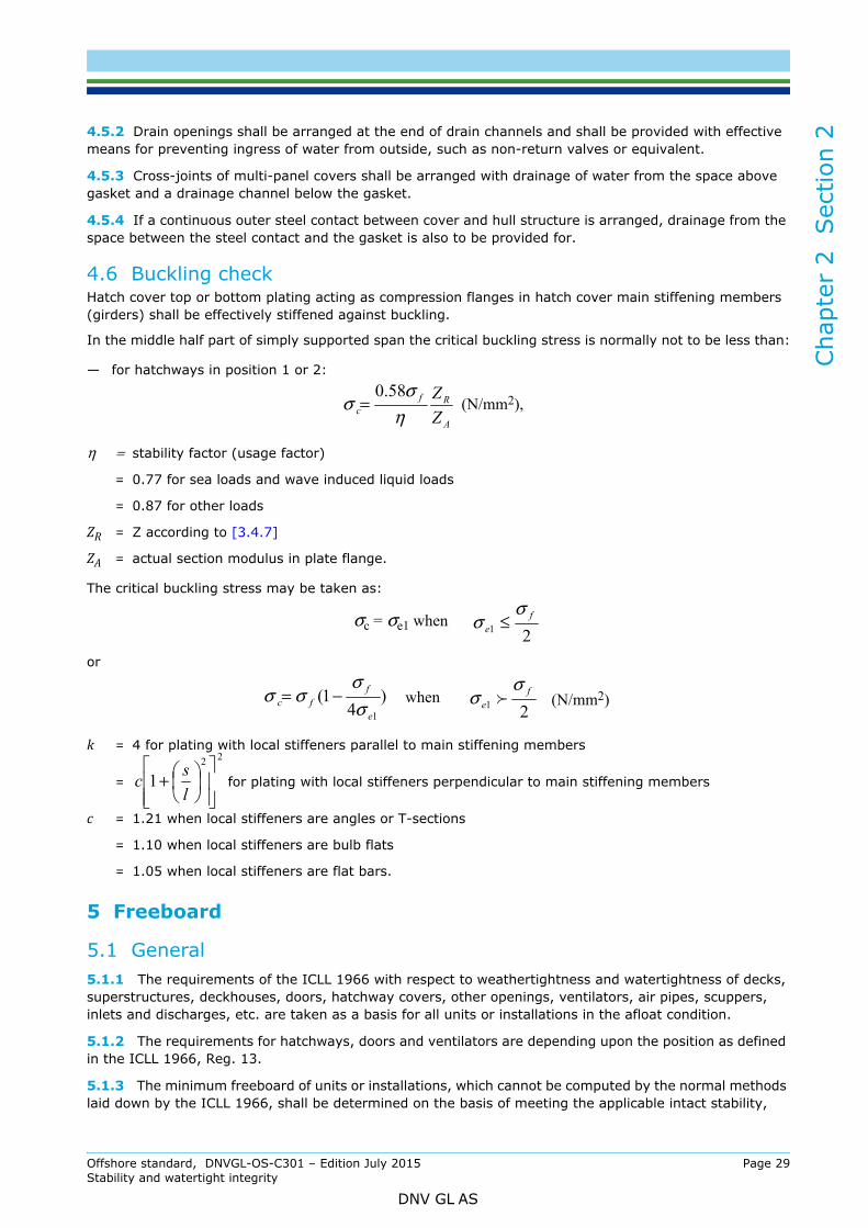
4.6 Buckling checkHatch cover top or bottom plating acting as compression flanges in hatch cover main stiffening members (girders) shall be effectively stiffened against buckling.
In the middle half part of simply supported span the critical buckling stress is normally not to be less than:
— for hatchways in position 1 or 2:
η = stability factor (usage factor)
= 0.77 for sea loads and wave induced liquid loads = 0.87 for other loads
ZR = Z according to [3.4.7]
ZA = actual section modulus in plate flange.
The critical buckling stress may be taken as:
or
k = 4 for plating with local stiffeners parallel to main stiffening members = for plating with local stiffeners perpendicular to main stiffening members
c = 1.21 when local stiffeners are angles or T-sections = 1.10 when local stiffeners are bulb flats = 1.05 when local stiffeners are flat bars.
5 Freeboard
5.1 General5.1.1 The requirements of the ICLL 1966 with respect to weathertightness and watertightness of decks, superstructures, deckhouses, doors, hatchway covers, other openings, ventilators, air pipes, scuppers, inlets and discharges, etc. are taken as a basis for all units or installations in the afloat condition.
5.1.2 The requirements for hatchways, doors and ventilators are depending upon the position as defined in the ICLL 1966, Reg. 13.
5.1.3 The minimum freeboard of units or installations, which cannot be computed by the normal methods laid down by the ICLL 1966, shall be determined on the basis of meeting the applicable intact stability,
A
Rfc Z
Zη
σσ
58.0= (N/mm2),
21f
e
σσ ≤σc = σe1 when
)4
1(1e
ffc σ
σσσ −=
21f
e
σσ when (N/mm2)
22
1
+lsc
Offshore standard, DNVGL-OS-C301 – Edition July 2015 Page 29Stability and watertight integrity
DNV GL AS
Cha
pter
2
Sec
tion
2
damage stability and structural requirements for transit and operational conditions while afloat. The freeboard shall not be less than that calculated in accordance with the ICLL 1966, where applicable.5.2 Self elevating units or installations5.2.1 Load lines for self elevating units are calculated under the terms of the ICLL 1966. When floating or when in transit from one operational area to another, the units shall be subject to all the conditions of assignment of the ICLL 1966 unless specifically excepted. The regulations of relevant national authorities shall also be observed.
5.2.2 Self elevating units or installations shall not be subject to the terms of the ICLL 1966 while they are supported by the seabed or are in the process of lowering or raising their legs.
5.2.3 In general, heights of hatch and ventilator coamings, air pipes, door sills, etc. in exposed positions and their means of closing are determined by consideration of both intact and damage stability requirements.
5.2.4 Side scuttles below freeboard deck shall be of the non-opening type with inside hinged deadlight.
5.3 Column stabilised units or installations5.3.1 Load lines for column stabilised units or installations shall be based on:
— the strength of the structure
— the air gap between waterline and deck structure
— the intact and damage stability requirements.
5.3.2 The conditions of assignment shall be based on the requirements of the ICLL 1966. The regulations of relevant national authorities shall also be observed.
5.3.3 In general, heights of hatch and ventilator coamings, air pipes, door sills, etc., in exposed positions and their means of closing are determined by consideration of both intact and damage stability requirements.
5.3.4 The freeboard deck (reference deck) is defined as the lowest continuous deck exposed to weather and sea, which has permanent means of closing and below which all openings are watertight closed at sea.
5.3.5 Side scuttles and windows, including those of non-opening type, or other similar openings, shall not be fitted below the freeboard deck.
5.3.6 For the first tier on the freeboard deck, the requirements as for position 2 in the ICLL 1966 apply with respect to openings, sill heights, coaming heights and weathertight closing appliances. Windows and side scuttles on first tier protecting openings leading below or volumes considered buoyant in the stability calculations are to be fitted with inside hinged deadlights. For units with a positive air gap; inside hinged deadlights for windows and side scuttles may be omitted.
For the second tier, weathertight closing appliances are required, but sill or coaming heights may be omitted.
For third tier and above, load line requirements will not apply.
In addition to load line requirements watertight or weathertight closing appliances may be required as deemed necessary by stability requirements, ref. Ch.2 Sec.1 [5.11] and Pt. Ch.2 Sec.2 [10.1].
5.3.7 Deckhouses and wells on the first and second tiers, which are not weathertight closed as described in [5.3.6], shall be provided with satisfactory drainage. The total drainage cross sectional area shall not be less than 0.30% of the deck area for the deckhouse or well. The drainage shall be arranged so that it will prevent accumulation of water in any part of the space.
Offshore standard, DNVGL-OS-C301 – Edition July 2015 Page 30Stability and watertight integrity
DNV GL AS
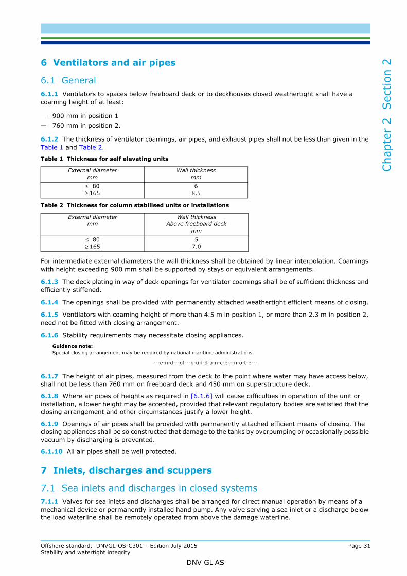
Cha
pter
2
Sec
tion
2
6 Ventilators and air pipes6.1 General6.1.1 Ventilators to spaces below freeboard deck or to deckhouses closed weathertight shall have a coaming height of at least:
— 900 mm in position 1— 760 mm in position 2.
6.1.2 The thickness of ventilator coamings, air pipes, and exhaust pipes shall not be less than given in the Table 1 and Table 2.
For intermediate external diameters the wall thickness shall be obtained by linear interpolation. Coamings with height exceeding 900 mm shall be supported by stays or equivalent arrangements.
6.1.3 The deck plating in way of deck openings for ventilator coamings shall be of sufficient thickness and efficiently stiffened.
6.1.4 The openings shall be provided with permanently attached weathertight efficient means of closing.
6.1.5 Ventilators with coaming height of more than 4.5 m in position 1, or more than 2.3 m in position 2, need not be fitted with closing arrangement.
6.1.6 Stability requirements may necessitate closing appliances.
Guidance note:Special closing arrangement may be required by national maritime administrations.
---e-n-d---of---g-u-i-d-a-n-c-e---n-o-t-e---
6.1.7 The height of air pipes, measured from the deck to the point where water may have access below, shall not be less than 760 mm on freeboard deck and 450 mm on superstructure deck.
6.1.8 Where air pipes of heights as required in [6.1.6] will cause difficulties in operation of the unit or installation, a lower height may be accepted, provided that relevant regulatory bodies are satisfied that the closing arrangement and other circumstances justify a lower height.
6.1.9 Openings of air pipes shall be provided with permanently attached efficient means of closing. The closing appliances shall be so constructed that damage to the tanks by overpumping or occasionally possible vacuum by discharging is prevented.
6.1.10 All air pipes shall be well protected.
7 Inlets, discharges and scuppers
7.1 Sea inlets and discharges in closed systems7.1.1 Valves for sea inlets and discharges shall be arranged for direct manual operation by means of a mechanical device or permanently installed hand pump. Any valve serving a sea inlet or a discharge below the load waterline shall be remotely operated from above the damage waterline.
Table 1 Thickness for self elevating units
External diametermm
Wall thicknessmm
≤ 80≥ 165
68.5
Table 2 Thickness for column stabilised units or installations
External diametermm
Wall thicknessAbove freeboard deck
mm≤ 80≥ 165
57.0
Offshore standard, DNVGL-OS-C301 – Edition July 2015 Page 31Stability and watertight integrity
DNV GL AS
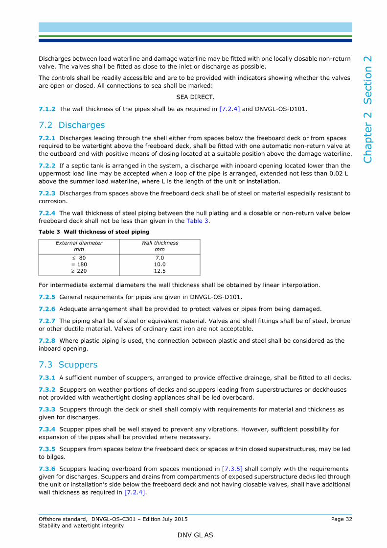
Cha
pter
2
Sec
tion
2
Discharges between load waterline and damage waterline may be fitted with one locally closable non-return valve. The valves shall be fitted as close to the inlet or discharge as possible.The controls shall be readily accessible and are to be provided with indicators showing whether the valves are open or closed. All connections to sea shall be marked:
SEA DIRECT.
7.1.2 The wall thickness of the pipes shall be as required in [7.2.4] and DNVGL-OS-D101.
7.2 Discharges7.2.1 Discharges leading through the shell either from spaces below the freeboard deck or from spaces required to be watertight above the freeboard deck, shall be fitted with one automatic non-return valve at the outboard end with positive means of closing located at a suitable position above the damage waterline.
7.2.2 If a septic tank is arranged in the system, a discharge with inboard opening located lower than the uppermost load line may be accepted when a loop of the pipe is arranged, extended not less than 0.02 L above the summer load waterline, where L is the length of the unit or installation.
7.2.3 Discharges from spaces above the freeboard deck shall be of steel or material especially resistant to corrosion.
7.2.4 The wall thickness of steel piping between the hull plating and a closable or non-return valve below freeboard deck shall not be less than given in the Table 3.
For intermediate external diameters the wall thickness shall be obtained by linear interpolation.
7.2.5 General requirements for pipes are given in DNVGL-OS-D101.
7.2.6 Adequate arrangement shall be provided to protect valves or pipes from being damaged.
7.2.7 The piping shall be of steel or equivalent material. Valves and shell fittings shall be of steel, bronze or other ductile material. Valves of ordinary cast iron are not acceptable.
7.2.8 Where plastic piping is used, the connection between plastic and steel shall be considered as the inboard opening.
7.3 Scuppers7.3.1 A sufficient number of scuppers, arranged to provide effective drainage, shall be fitted to all decks.
7.3.2 Scuppers on weather portions of decks and scuppers leading from superstructures or deckhouses not provided with weathertight closing appliances shall be led overboard.
7.3.3 Scuppers through the deck or shell shall comply with requirements for material and thickness as given for discharges.
7.3.4 Scupper pipes shall be well stayed to prevent any vibrations. However, sufficient possibility for expansion of the pipes shall be provided where necessary.
7.3.5 Scuppers from spaces below the freeboard deck or spaces within closed superstructures, may be led to bilges.
7.3.6 Scuppers leading overboard from spaces mentioned in [7.3.5] shall comply with the requirements given for discharges. Scuppers and drains from compartments of exposed superstructure decks led through the unit or installation’s side below the freeboard deck and not having closable valves, shall have additional wall thickness as required in [7.2.4].
Table 3 Wall thickness of steel piping
External diametermm
Wall thicknessmm
≤ 80= 180≥ 220
7.010.012.5
Offshore standard, DNVGL-OS-C301 – Edition July 2015 Page 32Stability and watertight integrity
DNV GL AS

Cha
pter
2
Sec
tion
2
8 Side scuttles and windows8.1 General8.1.1 Acceptable standards for side scuttles and windows are ISO 1751:1993 and ISO 3903:1993 with glass according to ISO 21005:2004 and testing according to ISO 614:1989. National standards equivalent to the ISO standards are also acceptable.
8.1.2 Side scuttles and windows in the first tier and second tier with direct access below the freeboard deck, shall have hinged inside deadlights arranged so that they can be effectively closed and secured watertight.
8.1.3 Deadlights as required in [8.1.2] may be hinged on the outside, provided there is easy access for closing.
8.1.4 No side scuttle shall be fitted in a position with its sill below a line drawn parallel to the freeboard deck. The lowest point shall be minimum 0.025 B above the summer load waterline, or 500 mm, whichever is the greater distance. B is the breadth of the unit or installation.
9 Testing of doors and hatch covers
9.1 Pressure testing of watertight doors and hatch covers9.1.1 Before installation (i.e. normally at the manufacturer) the watertight doors or hatch covers shall be hydraulically tested with exposure to the side most prone to leakage.
9.1.2 The test pressure shall correspond to the pressure height pd (see [3.4.5]) + 50 kN/m2 (5 m water), and the acceptance criteria shall be:
— no leakage for doors or hatch covers with gaskets— maximum water leakage 1 litre per minute for doors or hatch covers with metallic sealing.
9.2 Hose testing of watertight and weathertight doors and hatch coversAfter installation onboard all (every single) watertight and weathertight doors or hatch covers shall be hose tested. The water pressure shall be at least 0.2 N/mm2 (2 bar), and the nozzle shall be held at a distance of maximum 1.5 m from the door or hatch cover. No leakage shall be accepted.
As an alternative to hose testing, chalk testing may be applied under special circumstances upon acceptance by all parties involved.
9.3 Function testing of watertight doors and hatch coversAfter installation onboard the operation, control and alarm functions for all watertight doors and hatch covers shall be tested.
The following shall be verified:
a) It shall be possible to close all doors or hatch covers in one group simultaneously within 60 s from the control room.
b) It shall be possible to open and close the doors or hatch covers three times by means of a local device and stored energy.
c) It shall be possible for a person to pass through the doorway or hatchway and at the same time hold both handles in the “open position”.
d) It shall be possible to open the door or hatch cover locally from both sides, after being closed centrally, and the door or hatch cover shall close automatically after such opening.
e) The door or hatch cover shall be mechanically locked in closed position.f) The light and sound signals shall give warning when the door or hatch cover is closed centrally.g) The remote position indicator for doors or hatch covers shall function properly.h) The alarms for the following conditions shall function properly:
— start of standby pump
Offshore standard, DNVGL-OS-C301 – Edition July 2015 Page 33Stability and watertight integrity
DNV GL AS

Cha
pter
2
Sec
tion
2
— loss of power to control, alarm and indicating system— low pressure (below lowest permissible).
10 Closing arrangements for doors and hatch covers
10.1 Description of waterlines (beach lines)The following waterlines are required for Column-stabilised and Self-elevating units in order to indicate the extent of the watertight and weathertight integrity:
— Waterline A (watertight for Column-stabilised units); waterline showing equilibrium position at first intercept between righting and wind heeling moment curves in damage condition for damage cases according to Sec.1 [5.4.1], and waterline showing equilibrium position at first intercept (excluding wind) in damage condition for damage cases according to Sec.1 [5.4.2], whichever is the most severe (envelope curve).
— Waterline A (watertight for Self-elevating units); waterline showing equilibrium position at first intercept between righting and wind heeling moment curves in damage condition.
— Waterline B (weathertight for column-stabilised units); waterline according to area requirement of righting and wind heeling moment curves (Sec.1 [4.3.1]), the 7° range criterion (Sec.1 [5.4.1] 3 and [5.4.2] 3), and the 4 meters criterion (Sec.1 [5.4.1] 2), whichever is the most severe (envelope curve).
— Waterline B (weathertight for Self-elevating units); waterline according to area requirement of righting and wind heeling moment curves (Sec.1 [4.4.1]).
These lines should preferably be presented on the freeboard plan.
Guidance note:The beach lines required above can be omitted if all relevant openings are included in the stability calculations with the correct positions.
---e-n-d---of---g-u-i-d-a-n-c-e---n-o-t-e---
10.2 Description of location of openingsThe location of openings in relation to the waterlines are defined as (see Figure 1):
I Internal openings in watertight bulkheads, i.e. internal bulkheads assumed watertight in stabilitycalculations.
II External openings below deepest draught according to ICLL 1966.III External openings between deepest draught and freeboard deck.IV External openings above freeboard deck, submerged before equilibrium position at first intercept (line
A) between righting and wind heeling moment curves in damage condition.V External openings:
1) on first and second tier
2) submerged between equilibrium position at first intercept (line A) and waterline B.
VI External openings:
1) on and above third tier
2) above waterline B.
10.3 Operation, indication and lockingThe requirements for operation, indication and locking of doors and hatch covers are given in Table 4, in relation to the locations defined in [10.2].
Offshore standard, DNVGL-OS-C301 – Edition July 2015 Page 34Stability and watertight integrity
DNV GL AS
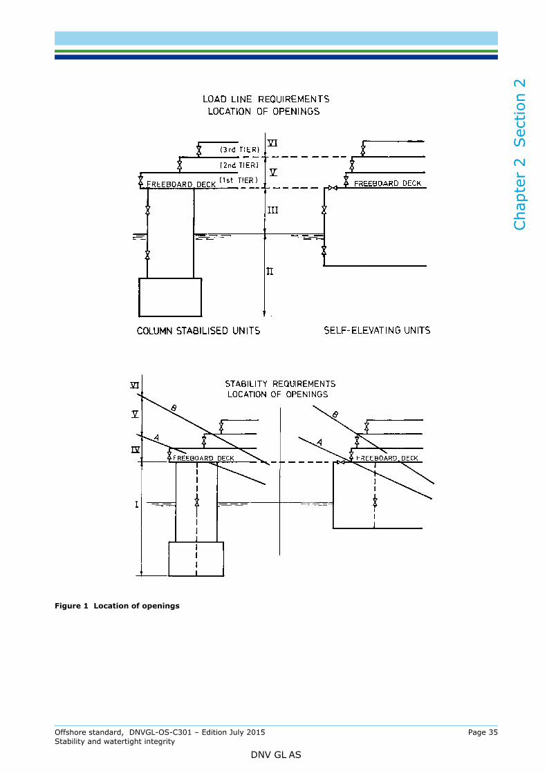
Cha
pter
2
Sec
tion
2
Figure 1 Location of openings
Offshore standard, DNVGL-OS-C301 – Edition July 2015 Page 35Stability and watertight integrity
DNV GL AS

Chapter 2 Section 2
Offshore standard, D
NVG
L-OS-C
301 – Edition July 2015 Page 36
Stability and w
atertight integrity
DN
V G
L A
S
Table 4 Requirements regarding operation, indication and locking of doors and hatch cover
al/ nal Comment Regulation
Mechanical locking in
closed position 3)
Note 1) MODU Code 3.6.5 X
Note 1), 2) and 4) MODU Code 3.6.5 X
Note 1), 4) and 5) MODU Code 3.6.5 X
ICLL X
ICLL X
MODU Code 3.6.7
Note 1) and 4)ICLL &
MODU Code 3.3 and 3.4
Note 1) and 4) MODU Code 3.7.22
oves, with built-in «mechanical» locking due to the
r hatch cover shall then be of the quick acting type.
while the unit or installation is afloat at sea. Bolted
Location Frequency of use
Type of door or hatch
cover
Remote control
Remote Indication
Audible or visual alarm Notice 4) Watertight/
WeathertightInternExter
I
Used POS Y Y Y Y WA INT
Norm. Closed S,H N Y Y Y WA INT
Perm. Closed S, H N N N Y WA INT
II Perm. Closed Bolted N N N N WA EXT
III Perm. Closed Bolted N N N N WA EXT
IV Perm. Closed Bolted N N N N WA EXT
V Norm. Closed H N N N Y WE EXT
VI Norm. Closed H N N N Y WE EXT
Y: YES, N: NO, WA: Watertight, WE: Weathertight, INT: Internal, EXT: External1) POS: Power Operated Sliding, S: Sliding, H: Hinged, Sliding door: moving along and supported by trackway gro
tapered form and friction, and a positive force is required to re-open the door.2) This option is only allowed for self elevating units and above deepest load line draught for other units. The door o3) Mechanical locking: by means of wedges, bars or similar devices, which are self-locking.4) The door or hatch cover shall be fitted with a notice board stating that the door or hatch cover is to be kept closed
manhole covers need not be so marked.5) Internal openings intended only to provide access for inspection.

Cha
pter
3
Sec
tion
1
CHAPTER 3 CERTIFICATION AND CLASSIFICATIONSECTION 1 GENERAL
1 Introduction
1.1 Application1.1.1 As well as representing DNV GL’s recommendations on safe engineering practice for general use by the offshore industry, the offshore standards also provide the technical basis for DNV GL classification, certification and verification services.
1.1.2 A complete description of principles, procedures, applicable class notations and technical basis for offshore classification is given by the DNV GL rules for classification of offshore units as listed in the table Table 1.
2 Design review
2.1 Documentation requirementsDocumentation for classification shall be in accordance with the NPS DocReq (DNV GL Nauticus Production System for documentation requirements) and DNVGL-CG-0168.
2.2 Specific classification requirementsThe computation of freeboard (see Ch.2 Sec.2 [5]) is not subject to classification. However, the requirements, including those relating to certification, of the International Convention on Load Lines 1966 (ILLC 1966) apply to all units and installations.
3 Certification of materials and components
3.1 General3.1.1 The product certification is a conformity assessment normally including both design and production assessment.
The production assessment includes inspection and testing during production and/or of the final product.
3.1.2 Components shall be certified consistent with its functions and importance for safety. The principles of categorisation of component certification are given in the relevant rules, see Table 1.
3.1.3 Product certification shall be documented by the following types of documents:
a) DNV GL Product Certificate (VL):A document signed by a DNV GL surveyor stating:
— conformity with rules and standard requirements— that tests are carried out on the certified product itself— that tests are made on samples taken from the certified product itself— that tests are performed in presence of the surveyor or in accordance with special agreements.
Table 1 DNV GL rules for classification - Offshore units
No. TitleDNVGL-RU-OU-0101 Offshore drilling and support unitsDNVGL-RU-OU-0102 Floating production, storage and loading unitsDNVGL-RU-OU-0103 Floating LNG/LPG production, storage and loading unitsDNVGL-RU-OU-0104 Self-elevating units
Offshore standard, DNVGL-OS-C301 – Edition July 2015 Page 37Stability and watertight integrity
DNV GL AS
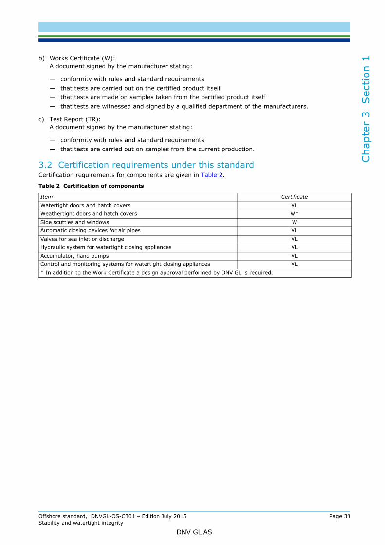
Cha
pter
3
Sec
tion
1
b) Works Certificate (W):A document signed by the manufacturer stating:— conformity with rules and standard requirements— that tests are carried out on the certified product itself— that tests are made on samples taken from the certified product itself— that tests are witnessed and signed by a qualified department of the manufacturers.
c) Test Report (TR):A document signed by the manufacturer stating:
— conformity with rules and standard requirements— that tests are carried out on samples from the current production.
3.2 Certification requirements under this standardCertification requirements for components are given in Table 2.
Table 2 Certification of components
Item CertificateWatertight doors and hatch covers VLWeathertight doors and hatch covers W*Side scuttles and windows WAutomatic closing devices for air pipes VLValves for sea inlet or discharge VLHydraulic system for watertight closing appliances VLAccumulator, hand pumps VLControl and monitoring systems for watertight closing appliances VL* In addition to the Work Certificate a design approval performed by DNV GL is required.
Offshore standard, DNVGL-OS-C301 – Edition July 2015 Page 38Stability and watertight integrity
DNV GL AS
SAF
DNV GLDriven by our purpose of safeguarding life, property and the environment, DNV GL enables organizations to advance the safety and sustainability of their business. We provide classification and technical assurance along with software and independent expert advisory services to the maritime, oil and gas, and energy industries. We also provide certification services to customers across a wide range of industries. Operating in more than 100 countries, our 16 000 professionals are dedicated to helping our customers make the world safer, smarter and greener.
ER, SMARTER, GREENER