Embed Size (px)
Citation preview

MicroSCADA Pro SYS600 9.4DNP 3.0 Slave Protocol

Trace back information:Workspace Main version a54

Contents
51 Copyrights .............................................................................................
72 Introduction ...........................................................................................72.1 This manual ..................................................................................82.2 Use of symbols .............................................................................82.3 Document conventions .................................................................92.4 Related documents .......................................................................
102.5 Document revisions ......................................................................
113 Safety information ................................................................................113.1 Backup copies ..............................................................................113.2 Fatal errors ...................................................................................
134 Instructions ...........................................................................................134.1 Communication .............................................................................134.2 Installation .....................................................................................134.3 Configuration ................................................................................134.3.1 Base system configuration ..............................................144.3.2 Communication system configuration .............................164.3.2.1 DNP 3.0 line layer .........................................334.3.2.2 DNP 3.0 station object ..................................464.3.2.3 Authentication attributes ................................554.3.2.4 Security attributes .........................................584.3.2.5 Autodialing attributes .....................................624.4 After configuration .........................................................................634.5 How to test the configuration ........................................................634.6 Serial cable wiring diagram ...........................................................654.7 Communication adjustment guidelines .........................................
675 Technical description ...........................................................................675.1 DNP 3.0 Protocol ..........................................................................675.2 Level of implementation ................................................................685.3 Supported process object types ...................................................685.4 Communication .............................................................................685.4.1 Communication modes ...................................................695.4.2 Protocol converter ...........................................................705.4.3 Handshaking ...................................................................705.4.4 DNP 3.0 in LAN/WAN .....................................................705.4.5 Addressing ......................................................................715.4.6 Internal indications ..........................................................715.4.7 Data flow .........................................................................
3
SYS600 9.4MicroSCADA Pro
DNP 3.0 Slave Protocol
1MRS758111
3.6.2016Issued:C/3.6.2016Version:
Configuration Manual

745.4.8 Device communication attributes ....................................815.5 Command procedures ..................................................................815.5.1 Command procedures in COM500i ................................825.5.2 Command procedures in SYS600 ..................................825.5.2.1 Command procedures for process data ........
855.5.2.2 Command procedures for the status of output
objects ...........................................................
865.5.2.3 Command procedures for initializing the NET
database .......................................................885.5.2.4 Command handling in DNP 3.0 protocol .......885.5.2.5 Command procedures for data commands ....
915.5.2.6 Command procedures for application and
system commands ........................................925.6 Signal engineering ........................................................................925.7 Status codes .................................................................................935.8 Device profile ................................................................................
Appendices
113A Configuration examples .......................................................................
115B Examples of communication system configuration ..........................119Index .......................................................................................................
4
1MRS758111MicroSCADA ProSYS600 9.4DNP 3.0 Slave ProtocolConfiguration Manual

1 Copyrights
The information in this document is subject to change without notice and should not beconstrued as a commitment by ABB Oy. ABB Oy assumes no responsibility for anyerrors that may appear in this document.
In no event shall ABB Oy be liable for direct, indirect, special, incidental or consequentialdamages of any nature or kind arising from the use of this document, nor shall ABB Oybe liable for incidental or consequential damages arising from the use of any softwareor hardware described in this document.
This document and parts thereof must not be reproduced or copied without writtenpermission from ABB Oy, and the contents thereof must not be imparted to a third partynor used for any unauthorized purpose.
The software or hardware described in this document is furnished under a license andmay be used, copied, or disclosed only in accordance with the terms of such license.
Copyright © 2016 ABB Oy. All rights reserved.
Trademarks
ABB is a registered trademark of ABB Group. All other brand or product namesmentioned in this document may be trademarks or registered trademarks of their respectiveholders.
Guarantee
Please inquire about the terms of guarantee from your nearest ABB representative.
Third Party Copyright Notices
List of Third Party Copyright notices are documented in "3rd party licenses.txt" andincluded in SYS600 and DMS600 installation packages.
5
SYS600 9.4MicroSCADA Pro
DNP 3.0 Slave Protocol
1MRS758111
3.6.2016Issued:C/3.6.2016Version:
Configuration Manual


2 Introduction
2.1 This manual
This manual provides thorough information on the use of DNP 3.0 Slave Protocol(Distributed Network Protocol) and information related to it. It describes how to configurethe base system and the communication system to establish communication to DNP 3.0master. DNP 3.0 protocol is standardized as IEEE standard 1815 - IEEE Standard forElectric Power Systems Communications -- Distributed Network Protocol (DNP3). TermDNP 3.0 is used in this manual and in the referenced tools.
In addition to this configuration, the base system needs to be configured for the processcommunication. For more information on this subject, see other manuals, for exampleSYS600 Application Objects or SYS600 COM500i User’s Guide.
The DNP 3.0 master in the Network Control Center needs to be configured together withthe DNP3.0 slave in COM500i.
DNP 3.0 slave
The DNP 3.0 slave protocol is mainly used for upper level communication betweenSYS600 (COM500i) and an NCC, as illustrated in Figure :
Figure 2.1: DNP Master sees the NET unit and the process behind it as a slave
The data from the process activates certain event channels and command procedures inthe base system. This command procedure forwards the information to the NET unit andthe DNP 3.0 master.
7
SYS600 9.4MicroSCADA Pro
DNP 3.0 Slave Protocol
1MRS758111
3.6.2016Issued:C/3.6.2016Version:
Configuration Manual

DNP 3.0 Slave Protocol (Distributed Network Protocol) can be configured to operate asTCP server and is thus exposed to attacks from the network. For more information, seeSYS600 Cyber Security Deployment Guideline, which collects instructions to hardenthe system as a whole.
2.2 Use of symbols
This publication includes warning, caution and information symbols where appropriateto point out safety-related or other important information. It also includes tips to pointout useful hints to the reader. The corresponding symbols should be interpreted as follows:
!Warning icon indicates the presence of a hazard which couldresult in personal injury.
Caution icon indicates important information or a warningrelated to the concept discussed in the text. It might indicatethe presence of a hazard, which could result in corruption ofsoftware or damage to equipment/property.
Information icon alerts the reader to relevant factors andconditions.
Tip icon indicates advice on, for example, how to design aproject or how to use a certain function.
Although warning hazards are related to personal injury, and caution hazards areassociated with equipment or property damage, it should be understood that operationof damaged equipment could, under certain operational conditions, result in degradedprocess performance leading to personal injury or death. Therefore, comply fully withall warnings and caution notices.
2.3 Document conventions
The following conventions are used for the presentation of material:
• The words in names of screen elements (for example, the title in the title bar of adialog, the label for a field of a dialog box) are initially capitalized.
• Capital letters are used for file names.• Capital letters are used for the name of a keyboard key if it is labeled on the keyboard.
For example, press the CTRL key. Although the Enter and Shift keys are not labeledthey are written in capital letters, e.g. press ENTER.
• Lowercase letters are used for the name of a keyboard key that is not labeled on thekeyboard. For example, the space bar, comma key and so on.
8
1MRS758111MicroSCADA ProSYS600 9.4DNP 3.0 Slave ProtocolConfiguration Manual

• Press CTRL+C indicates that the user must hold down the CTRL key while pressingthe C key (in this case, to copy a selected object).
• Press ALT E C indicates that the user presses and releases each key in sequence (inthis case, to copy a selected object).
• The names of push and toggle buttons are boldfaced. For example, click OK.• The names of menus and menu items are boldfaced. For example, the File menu.
- The following convention is used for menu operations: Menu Name > MenuItem > Cascaded Menu Item. For example: select File > Open > New Project.
- The Start menu name always refers to the Start menu on the Windows TaskBar.
• System prompts/messages and user responses/input are shown in the Courier font.For example, if the user enters a value that is out of range, the following messageis displayed: Entered value is not valid.The user may be told to enter the string MIF349 in a field. The string is shown asfollows in the procedure: MIF349
• Variables are shown using lowercase letters: sequence name
2.4 Related documents
The following SYS600 manuals should be available for reference during the use of thismanual:
MRS numberName of the manual
1MRS758110SYS600 9.4 DNP 3.0 Master Protocol
1MRS758085SYS600 9.4 Communication Gateway, COM500i
1MRS758100SYS600 9.4 System Configuration
1MRS758115SYS600 9.4 System Objects
1MRS758113SYS600 9.4 Application Objects
1MRS758118SYS600 9.4 Cyber Security DeploymentGuideline
The following documents of the DNP 3.0 protocol are available via the DNP UsersGroup:
• DNP 3.0 DATA LINK LAYER• DNP 3.0 APPLICATION LAYER• DNP 3.0 DATA OBJECT LIBRARY• DNP 3.0 TRANSPORT FUNCTIONS• DNP 3.0 SUBSET DEFINITIONS
The same information is presented in IEEE Standard 1815.
Other related documents:
• Product documentation of the used modem
9
SYS600 9.4MicroSCADA Pro
DNP 3.0 Slave Protocol
1MRS758111
3.6.2016Issued:C/3.6.2016Version:
Configuration Manual

2.5 Document revisions
HistoryDateRevision numberVersion
New document16.5.20149.4A
Document updated3.6.20159.4 FP1B
Document updated3.6.20169.4 FP2C
10
1MRS758111MicroSCADA ProSYS600 9.4DNP 3.0 Slave ProtocolConfiguration Manual

3 Safety information
This section has information on the prevention of hazards and taking backups from thesystem.
3.1 Backup copies
Taking backup copies
We recommend taking backup copies before making any changes, especially ones thatmight have side effects. Software and data need to be copied to another place.
Backup copying makes it easier to restore the application software in case of disk crashor other severe failure where stored data is lost. It is therefore recommended that backupcopies are taken regularly.
There should be at least two system backup copies and two application copies. A newbackup is copied over the oldest backup. This way the latest version is always available,even if the backup procedure fails.
Detailed information on how to take backup copies should be delivered to the customerwith the application.
System backup
Usually a system back up is taken after the application is made. It should be taken againwhen changes are made to the SYS600 system. This is required when the driverconfiguration or the network setup is changed.
Application backup
An application backup is also taken at the same time with the system backup, after theapplication is made. It should be taken again when changes are made to the application,for example, if pictures or databases are edited or new pictures are added.
3.2 Fatal errors
A fatal error is an error that causes a breakdown or a locked situation in the SYS600program execution.
Handling
In case of a fatal error:
1. Write down the possible SYS600 error messages.2. Shut down the SYS600 main program. If this cannot be done in the SYS600 Control
Panel, try to end the task in Windows Task Manager.
11
SYS600 9.4MicroSCADA Pro
DNP 3.0 Slave Protocol
1MRS758111
3.6.2016Issued:C/3.6.2016Version:
Configuration Manual

Files may be damaged if the base system computers areshut down by switching the power off.
3. The data kept in the main memory at the moment of a fatal error is placed in thedrwtsn32.log file with Windows 2003 Server, Windows XP and earlier. By defaultit is placed under %SYSTEMDRIVE%\Documents And Settings\AllUsers\Application Data\Microsoft\Dr Watson. Log and dump file paths can bechecked with the drwtsn32 application. (Start -> run -> drwtsn32.exe). Analyze andcopy the data in these files.Starting with Windows Server 2008 and Windows 7 the crash handling has changed.The location of the dump files can be read from the registry under the keyHKEY_LOCAL_MACHINE\SOFTWARE\Microsoft\Windows\Windows ErrorReporting\LocalDumps. The DumpFolder value tells the location of the dump files.Collect the data from this location.
4. Restart the system.
Report the program break-down together with the possible SYS600 error messages andthe information from the drwtsn32.log file to the SYS600 supplier.
Status codes
Error messages in SCIL are called status codes. A list of status codes and shortexplanations for them can be found in SYS600 Status Codes.
12
1MRS758111MicroSCADA ProSYS600 9.4DNP 3.0 Slave ProtocolConfiguration Manual

4 Instructions
4.1 Communication
In SYS600 the DNP 3.0 Slave protocol is implemented only in the PC-NET software.PC-NET unit communicates over an INTEGRATED link and via the serial or LAN portsof the base system computer.
Setting the attributes of SYS600 system objects can modify the communicationparameters.
The base system considers each DNP 3.0 Slave device as a station that has been createdto a line of a NET unit. Each DNP 3.0 station works as a protocol converter that convertsdata between the internal protocol of SYS600 and the DNP 3.0 protocol.
The protocol can be used with virtual serial ports by using a special setting of the lineattributes. See NET line attribute CM for more information.
4.2 Installation
The SYS600 installation is required.
4.3 Configuration
Configuration can be made either by using the System Configuration Tool or by usingSCIL statements. For more information on the System Configuration Tool, see SYS600System Configuration manual, chapter "PC-NET start-up with System ConfigurationTool" and "System Configuration Tool". The usage of the System Configuration Toolis recommended, but if there is a need to create the communication configuration usingSCIL, it is instructed in the following chapters. In this case, the configuration can bedivided into two parts:
The configuration can be divided into two parts:
• Base system configuration• Communication system configuration
The attribute descriptions presented in chapter 'Communication system configuration'are the same for configurations created with System Configuration Tool or with SCIL.
4.3.1 Base system configuration
It is assumed here that the base system configuration for objects other than thecommunication has been made according to the instructions in the System Configurationmanual.
13
SYS600 9.4MicroSCADA Pro
DNP 3.0 Slave Protocol
1MRS758111
3.6.2016Issued:C/3.6.2016Version:
Configuration Manual

The extra steps needed to configure the communication are:
1. Define a node number for a PC_NET instance.2. Reserve a link number for a PC_NET instance. Creating the link as instructed in
step 6 starts the PC_NET instance.3. Create the base system STA object for each remote IED (master function) or for
each NCC connection (slave function).
• DNP 3.0 Slave protocol uses the station type DNP (STY type 30)The STA objects are created to SYS_BASCON.COM using the template or with aseparate creation sequence. If the template is not used, the sequence should containthe line:
#create STA'Sta_Nb':B = %Sta
where 'Sta_Nb' is the number of the station object in the base system. %Sta is a listobject which should contain at least the following settings: TT = "EXTERNAL",ST = station type, ND = node number defined in step 1 and TN = translated objectnumber (usually the same as 'Sta_Nb'. See SYS600 System Objects manual for moreinformation on the base system object attributes for STA object).
4. Edit the PC_NET.CF1 according to the description in chapter "Start-up definitionfile PC_NET.CF1" in the SYS600 System Configuration manual
5. Create a command procedure which creates the lines and stations to the NET object(= pc_net instance) using the S-attributes.See Section 4.3.2 Communication system configuration for more information onthe attribute setting. A sample creation script is presented at the end of this manual.
6. Create a command procedure which creates the link of type 'INTEGRATED' to thebase system. This procedure should contain the line:
#set LIN'i_Integrated_Link_Number':BLT = "INTEGRATED"
where 'i_Integrated_Link_Number' is the number of the link reserved in step 2. ThePC_NET executable is defined with the SC attribute of the link and it must set beforesetting of the LT attribute.
The testing of the communication system can be done as follows:
1. Execute the procedure created in step 6. This starts the PC_NET instance and enablethe setting of the S-attributes.
2. Execute the procedure created in step 5. If the lines and stations are set to IU = 1(i.e. they are in use) and the configuration is correct and complete in both ends, thecommunication starts.
For automatic start-up of the communication, the created command procedures must beattached to the APL_INIT_1:C procedure.
4.3.2 Communication system configuration
Each NET instance contains a set of system objects which specify the existence and theusage of the communication lines and the station objects connected to those lines. These
14
1MRS758111MicroSCADA ProSYS600 9.4DNP 3.0 Slave ProtocolConfiguration Manual

objects can be created, modified and deleted by SCIL, and setting the attributes definesthe functionality of these objects.
Access to the attributes can be one of the following:
• Read-only: The attribute can only be read. There are still a few exceptions in whichthe values can be reset.
• Write-only: The attribute can only be written (set).• Read, conditional write: The attribute can be both read and written, but the object
must be set out of use (IU = 0) before writing.• No limitations: The attribute can be both read and written without limitations.
The configuration of the communication system in SYS600 can be divided into twolayers: line layer and station layer. Both of these layers have a specific functionality anda set of attributes of their own.
The purpose of the communication system configuration is to:
• Create all the system objects needed to establish communication between the masterand the slave. Related attributes for creation are PO (Line) and DV (Station).
• Adjust the values of the system object attributes to match the physical communicationchannel and the properties of the remote partner/partners. The menu selection'Configuration->Preview->PC_NET' in the System Configuration Tool may providean example of the SCIL based configuration script of any setup.
Setting the attribute values
All the line and station attributes have sensible default values but the value of eachattribute must be checked against the requirements of the actual communication system.
The attribute values depend on:
• The physical communication media (for example leased telephone line, radio link,power line carrier), which affects the attributes of the line, such as the baud rate andparity.
• The network topology used (point-to-point, multi-drop), which affects the link type.• The size (number of stations) of the system, which affects the timeout parameters;
the slower the media and larger the system, the longer timeouts are needed.• The remote system(s), which affects both the line and station attributes, and also
the message types used.
Network topologies
The implementation of the DNP 3.0 Slave protocol in SYS600 supports direct and serialbus topologies. The direct topology (point-to-point) can be a direct physical cable frompoint-to-point, a two-node radio, or modem network. The serial bus topology (multi-drop)is commonly made up of many modems with their outputs/inputs tied together, orconnected using a star-coupler.
The DNP 3.0 link layer supports the multiple-slave and peer-to-peer communicationmethods. In peer-to-peer communication, all the stations act as slave data links andcollisions are possible as no station has a higher priority, and all of them can transmit
15
SYS600 9.4MicroSCADA Pro
DNP 3.0 Slave Protocol
1MRS758111
3.6.2016Issued:C/3.6.2016Version:
Configuration Manual

spontaneously. SYS600 uses random delay of retransmission as a collision avoidancemethod. When DNP 3.0 over LAN/WAN is used (TCP/IP or UDP/IP), the same topologiesare used. In version 9.3 FP2 and newer, it is also possible that multiple station objectsare sharing the same internet address in the configuration. See Figure 4.1
Figure 4.1: Network topologies
When making the DNP connection, an agreement about the used communicationparameters should be made with the supplier or owner of the master system.
4.3.2.1 DNP 3.0 line layer
The line process of a NET unit performs the functions of the line layer. The purpose ofthe line layer is to send and receive messages to/from external devices using the DNP3.0 protocol. By using the DNP 3.0 terminology, this means that the data link layerprovides transfer of Link Service Data Units (LSDU) across the physical link. LSDUsare user data fragments small enough to fit into the FT3 frame format. The applicationlayer of a NET unit is responsible for assembling and disassembling messages intoLSDUs. The line layer provides frame synchronization and link control.
According to the DNP 3.0 documentation, the link layer performs the following functions:
• Exchange of LSDUs between peer DNP 3.0 data links• Error notification to data link user• Sequencing of LSDUs• Prioritized LSDU delivery• Quality LSDU delivery
16
1MRS758111MicroSCADA ProSYS600 9.4DNP 3.0 Slave ProtocolConfiguration Manual

• Performing message retries• Frame Count Bit (FCB)• Data Flow Control (DFC)• Synchronizing and handling of the Frame Count Bit in the control word• Setting and clearing the Data Flow Control bit based on buffer availability• Packing user data into the defined frame format and transmitting the data to the
physical layer• Unpacking the frames that are received from the physical layer into user data• Controlling all aspects of the physical layer• Responding to all valid frames (function codes) received from the physical layer
Line layer attributes
The following attributes can be used for configuring DNP 3.0 master lines in SYS600.
In UseIU
Indicates whether the line is in use (value 1) or not in use (value 0).
IntegerData type:
0 or 1Value:
1...12 (NET line numbering)Index range:
0Default value:
No limitationsAccess:
Local AddressLD
The IP address that is used locally. It is necessary to set this attribute when the computerhas multiple IP addresses and it is defined which address the created line must use. Thisattribute must be set before the line has been taken into use for the first time. An emptystring in LD means that the default IP address of the computer is used. The value ofLD cannot be modified after the line has been taken into use for the first time. This at-tribute is used only in LAN mode of the protocol.
TextData type:
String containing a valid IP address, max 230 characters.Value:
Empty stringDefault value:
1... 12 (NET line numbering)Index range:
Read, conditional writeAccess:
This attribute accepts the IP address in form:
#SET NET1:SLD1="192.168.1.10"
The standard TCP port of 20000 specified for DNP 3.0 over LAN is used if the portnumber is not explicitly specified. If a non-standard port for the line is needed, the portnumber should be separated with a semicolon:
#SET NET1:SLD1=”192.168.1.1;20001” ;server port = 20001, (no spaces allowed)
17
SYS600 9.4MicroSCADA Pro
DNP 3.0 Slave Protocol
1MRS758111
3.6.2016Issued:C/3.6.2016Version:
Configuration Manual

The defined port number must be between range 1..65535. The operating system andother applications running in the same computer may cause limitations to the availabilityof the port numbers. The same local address and port cannot be used by multiple slavelines. This means that if the lines are using the standard TCP port 20000, a unique IPaddress must defined for each DNP 3.0 slave line.
There is an internal limitation which prohibits the use of thesame local IP address and the same line number multiple times.This applies to all PC_NET protocols using LAN.
Example:
It is not possible to have
IEC104 master in Line 1 in PC_NET 1 withLD="192.168.1.1"
and
DNP3.0 slave in Line 1 in PC_NET 2 withLD="192.168.1.1"
the configuration must be changed to
IEC104 master in Line 2 in PC_NET 1 withLD="192.168.1.1"
and
DNP3.0 slave in Line 1 in PC_NET 2 withLD="192.168.1.1"
or to
IEC104 master in Line 1 in PC_NET 1 withLD="192.168.1.1"
and
DNP3.0 slave in Line 1 in PC_NET 2 withLD="192.168.1.2"
The limitation is present only when the same local IP addressis used. An easy workaround is to configure multipleIP-addresses which are using the same adapter. If this is notpossible, setting a unique value for the NET node attribute LPredefines the internally used ports for the NET node and no
18
1MRS758111MicroSCADA ProSYS600 9.4DNP 3.0 Slave ProtocolConfiguration Manual

conflict takes place. See SYS600 System Objects manual formore information about the NET Node attribute LP.
ProtocolPO
The data transfer protocol used on the line. The line is defined to the NET by settingthis attribute. By setting the attribute to 0 the line definition including all the line attrib-utes are deleted.
IntegerData type:
0...45Value with DNP 3.0 Slave protocol : 35
Value:
1...12 (NET line numbering)Index range:
Read, conditional writeAccess:
System Device NameSD
Associates the NET line numbers of PC-NET with the device names of the physicalchannels of serial ports.By default, the line number 1 is connected to the COM1, the line 2 to the COM2 andso on. By using the SD attribute, it is possible to override these default values. Thismay be necessary if the COM ports are used as NET lines or if, for example, a Rocket-Port card is used.
TextData type:
See aboveValue:
1...12 (NET line numbering)Index range:
Read, conditional writeAccess:
When using DNP 3.0 over LAN, the SD attribute defines the used connection type.Possible types are TCP and UDP.
#SET NET’NET’:SSD’LINE’ = “TCP” ;line uses TCP connection
#SET NET’NET’:SSD’LINE’ = “UDP” ;line uses UDP connection
Buffer Pool SizePS
Specifies the number of message buffers reserved for the line. Fixed buffer poll sizesare used in versions 9.3 FP1 and newer and this attribute is retained because of thebackward compatibility. Setting the value for PS is not possible anymore. See the at-tributes PS, NB and PB from the System Objects manual for more information.
IntegerData type:
1...250Value:
1...12 (NET line numbering)Index range:
Read (conditional write accepted but has no effect)Access:
19
SYS600 9.4MicroSCADA Pro
DNP 3.0 Slave Protocol
1MRS758111
3.6.2016Issued:C/3.6.2016Version:
Configuration Manual

Baud RateBR
Transmission rate used on the line. The attribute is meaningless if the line operates inLAN/WAN mode.
IntegerData type:
1...19200 (384 = 38400 bauds, 576 = 57600 bauds)Value:
Bits / sUnit:
1...12 (NET line numbering)Index range:
9600Default value:
Read, conditional writeAccess:
ParityPY
Specifies the parity check (if any) used for the characters transferred on the line. Theattribute is meaningless, if the line operates in LAN/WAN mode.
IntegerData type:
0 = no parity checkValue:
1 = odd parity
2 = even parity
1...12 (NET line numbering)Index range:
2Default value:
Read, conditional writeAccess:
Receiver Data Bit CountRD
Specifies the number of data bits in each received character. The attribute is meaningless,if the line operates in LAN/WAN mode.
IntegerData type:
5, 6, 7 or 8Value:
Data bitsUnit:
1...12 (NET line numbering)Index range:
8Default value:
Read, conditional writeAccess:
Stop BitsSB
Specifies the number of stop bits attached to each transmitted character. The attributeis meaningless, if the line operates in LAN/WAN mode.
IntegerData type:
1 or 2Value:
20
1MRS758111MicroSCADA ProSYS600 9.4DNP 3.0 Slave ProtocolConfiguration Manual

Stop BitsSB
Stop bitsUnit:
1...12 (NET line numbering)Index range:
1Default value:
Read, conditional writeAccess:
Transmitter Data Bit CountTD
Specifies the number of data bits in each transmitted character. The attribute is mean-ingless, if the line operates in LAN/WAN mode.
IntegerData type:
5, 6, 7 or 8Value:
Data bitsUnit:
1...12 (NET line numbering)Index range:
8Default value:
Read, conditional writeAccess:
Polling DelayPD
Delay (in milliseconds) between "test function of link" commands. The purpose of thiscommand is to ensure that the communication to the slave/master is open. If this attributeis set to zero, the "test function of link" command is not sent. The link testing can alsobe controlled with the line attribute OM, bit 2.
IntegerData type:
0... 65535Value:
MillisecondsUnit:
1...12 (NET line numbering)Index range:
5000Default value:
Read, conditional writeAccess:
Maximum Message LengthML
Maximum length of an outgoing data link fragment (LPDU). This length is the amountof user data without checksums.
IntegerData type:
50...249Value:
OctetsUnit:
1...12 (NET line numbering)Index range:
230Default value:
21
SYS600 9.4MicroSCADA Pro
DNP 3.0 Slave Protocol
1MRS758111
3.6.2016Issued:C/3.6.2016Version:
Configuration Manual

Maximum Message LengthML
No limitationsAccess:
Maximum Random Delay for RetransmissionXR
Random transmission delay is a simple collision avoidance method used in DNP 3.0lines. When unsolicited responses are enabled for slave stations on a multi-drop line,there is a possibility that several slave devices send messages at the same time. Thismessage collision is seen as a timeout in a slave station since the master is not respond-ing. The XR attribute limits the possibility that two devices retransmit messages at thesame time.This attribute can also be used for setting the priorities of the slave stations: the stationwith the smallest retransmission delay has the highest priority.
IntegerData type:
0...65535Value:
MillisecondsUnit:
1...12 (NET line numbering)Index range:
0Default value:
No limitationsAccess:
Transmission Wait DelayTW
Specifies the transmission delay in milliseconds. The transmission delay is the timethat the NET must wait after receiving a CTS (Clear to Send) signal until starting thetransmission of a message.
IntegerData type:
0...65535Value:
MillisecondsUnit:
1...12 (NET line numbering)Index range:
5Default value:
No limitationsAccess:
22
1MRS758111MicroSCADA ProSYS600 9.4DNP 3.0 Slave ProtocolConfiguration Manual

Figure 4.2: TW attribute
CTS DelayDE
The maximum waiting time of the rising edge of the CTS signal after the activation ofthe RTS signal. Timeout causes a CTS error and the transmission does not start. A linedisconnection often leads to a CTS error.
IntegerData type:
0...65535Value:
MillisecondsUnit:
1...12 (NET line numbering)Index range:
50Default value:
Read, conditional writeAccess:
Figure 4.3: DE attribute
23
SYS600 9.4MicroSCADA Pro
DNP 3.0 Slave Protocol
1MRS758111
3.6.2016Issued:C/3.6.2016Version:
Configuration Manual
In the Figure 4.3 the smaller DE value causes a CTS error. Asuitable DE value varies with each system.
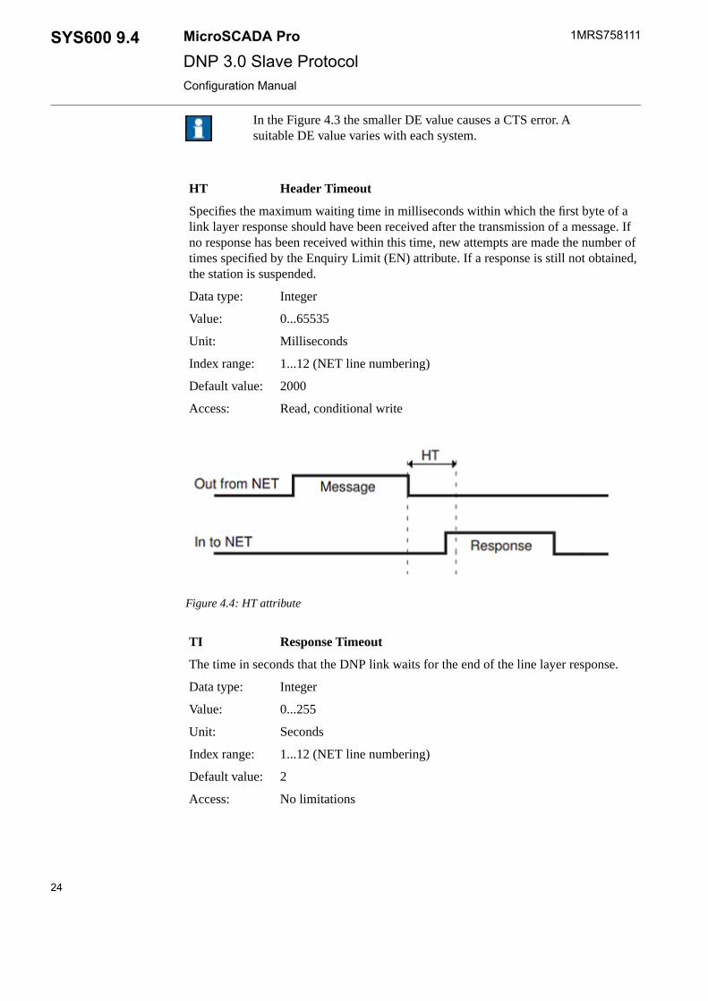
Header TimeoutHT
Specifies the maximum waiting time in milliseconds within which the first byte of alink layer response should have been received after the transmission of a message. Ifno response has been received within this time, new attempts are made the number oftimes specified by the Enquiry Limit (EN) attribute. If a response is still not obtained,the station is suspended.
IntegerData type:
0...65535Value:
MillisecondsUnit:
1...12 (NET line numbering)Index range:
2000Default value:
Read, conditional writeAccess:
Figure 4.4: HT attribute
Response TimeoutTI
The time in seconds that the DNP link waits for the end of the line layer response.
IntegerData type:
0...255Value:
SecondsUnit:
1...12 (NET line numbering)Index range:
2Default value:
No limitationsAccess:
24
1MRS758111MicroSCADA ProSYS600 9.4DNP 3.0 Slave ProtocolConfiguration Manual

Figure 4.5: TI attribute
A slow communication speed and a long response might causeerror with too small TI attribute value.
RTS Keepup DelayRY
This attribute defines how long time the RTS-pin of the RS232-port is kept in the signalstate after the serial driver completes the write operation. The write operation heremeans a transmission of any message. See also line attribute CM (Com Port Mode),bit 3.
IntegerData type:
0...20Value:
Bytes (absolute time depends on baudrate)Unit:
1...12 (NET line numbering)Index range:
1Default value:
Read, conditional writeAccess:
25
SYS600 9.4MicroSCADA Pro
DNP 3.0 Slave Protocol
1MRS758111
3.6.2016Issued:C/3.6.2016Version:
Configuration Manual

Figure 4.6: RY attribute
RTS Keep Up Padding CharactersRK
The number of padding characters (null characters) inserted to the end of a telegram todelay the passivation of the RTS (Request To Send) signal.
IntegerData type:
0...255Value:
1...12 (NET line numbering)Index range:
0Default value:
Read, conditional writeAccess:
Figure 4.7: RK attribute
26
1MRS758111MicroSCADA ProSYS600 9.4DNP 3.0 Slave ProtocolConfiguration Manual

Instead of using RK attribute, the RTS Keepup Delay (RY)attribute can be used.
Receive Interrupt Enable DelayRI
Defines the delay in milliseconds after which the receiver of a NET line is enabled aftera message has been issued. If the given value is too big, the first characters of the re-sponse are not necessarily received.
IntegerData type:
0...255Value:0 = receiver is always enabled
MillisecondsUnit:
1...12 (NET line numbering)Index range:
0Default value:
No limitationsAccess:
Figure 4.8: RI attribute
Enquiry LimitEN
Specifies the maximum number of times that a message is retransmitted after a timeout.
IntegerData type:
1...255Value:
1...12 (NET line numbering)Index range:
1Default value:
Read, conditional writeAccess:
27
SYS600 9.4MicroSCADA Pro
DNP 3.0 Slave Protocol
1MRS758111
3.6.2016Issued:C/3.6.2016Version:
Configuration Manual

Modem SignalSG
An attribute for direct supervision and control of the state of the modem signal. Thisattribute applies to all protocols. It is used for diagnostics and testing.If the incoming signal DCD or CTS is wanted to have a simulated high value all thetime, value = 1 can be written to these signals. This feature may be necessary for easiercabling or with virtual serial ports. If value = 0 is written to these signals, the actualstate of signal is used. The default mode of operation is the actual state. See also attributeCM Com Port Mode.
IntegerData type:
0 = Passive signal1 = active signal
Value:
DCD and CTS signalsIncoming:
DTR signalOutgoing:
100 * line no + signal no. Signal no. 5 = CTS, 8 = DCD, 20 = DTRIndex range:
Read-only, write possible to signals 5 = CTS and 8 = DCDAccess:
Examples:
#SET NET1:SSG208 = 1 ; line 2 of NET1 should behave as DCD is 'high' all thetime
#SET NET1:SSG205 = 1 ; line 2 of NET1 should behave as CTS is 'high' all thetime
#SET NET1:SSG208 = 0 ; line 2 of NET1 should use the actual state of the DCD
#SET NET1:SSG205 = 0 ; line 2 of NET1 should use the actual state of the CTS
COM Port ModeCM
This attribute consists of a set of flags which control the behavior and functionality ofthe serial port of the line. Each flag is one bit of this attribute. This attribute is meaning-less, if the line operates in LAN/WAN mode.
IntegerData type:
0 ... 15 (see below)Value:
0Default value
1...12 (NET line numbering)Index range:
Read, conditional writeAccess:
UART error handlingBit 0:When this bit is 0, the UART errors are read before the bytes are readfrom the serial port. This is the default mode.When the bit is 1, the UART errors are read as a separate operationafter the bytes are read from the serial port. This mode is similar toPC_NETs older than 9.2SP2 and it does not detect all errors detectedby the serial port hardware. If the line has a lot of disturbances, thismode may result in better performance than the default mode.
28
1MRS758111MicroSCADA ProSYS600 9.4DNP 3.0 Slave ProtocolConfiguration Manual

COM Port ModeCM
Simulated high of the CTS signalBit 1:When this bit is 0, the actual state of the CTS signal is used in theprotocol. This is the default mode.When this bit is 1, the CTS signal is simulated to be in the high stateall the time and the line behaves according to that. This setting maybe necessary with a virtual serial port or for easier cabling.
Simulated high of the DCD signalBit 2:When this bit is 0, the actual state of the DCD signal is used in theprotocol. This is the default mode.When this bit is 1, the DCD signal is simulated to be in the high stateall the time and the line behaves according to that. This setting maybe necessary with a virtual serial port or for easier cabling.
Calculated RTS Keep up timeBit 3:When this bit is 0, the keep up time of the RTS signal is not calculatedusing the length of the message but it is assumed that the driver ofthe serial port blocks the execution of the sending process until themessage is actually sent. This setting should be used if the setting'Wait on physical transmission before completing write' or similar isselected in the driver for the port in question. The tuning of the RTSkeep up time should be done with line attribute RY. This is the defaultsetting.When this bit is 1, the keep up time of the RTS signal is calculatedusing the length of the sent message and the baudrate of the port. TheRTS keep up time defined with the line attribute RY is added to thecalculated time. This setting is not needed if the setting 'Wait onphysical transmission before completing write' or similar is selectedin the driver for the port in question. This setting is the most commonwith the virtual serial ports, too.If the serial driver does not provide setting 'Wait on physical transmis-sion before completing write' or similar and RTS signal is activelyused by the modem hardware, it is worth to test both alternatives. Foraccurate analysis using protocol analyzer function, see also the descrip-tion of the bit 2 of the line attribute AU Analyzer Usage.
!Having a simulated value in CTS or DCD may have an effecton how a RS-232 line disconnection is detected and reportedto the MicroSCADA application.
Message IdentificationMI
Object address of system messages.
IntegerData type:
29
SYS600 9.4MicroSCADA Pro
DNP 3.0 Slave Protocol
1MRS758111
3.6.2016Issued:C/3.6.2016Version:
Configuration Manual

Message IdentificationMI
1...32760Value:
1...12 (NET line numbering)Index range:
6000 + (100 * NET number) + line numberDefault value:
Read, conditional writeAccess:
Message ApplicationMS
The number of the application that is the receiver of the system messages generated bythe line.
IntegerData type:
1...250Value:
1Default value:
1...12 (NET line numbering)Index range:
Read, conditional writeAccess:
Link TypeLK
The type of data link connection used on the line.The states of the CTS and DCD signals of the serial port can have simulated values.The usage of this feature may be necessary, if the line uses a virtual serial port or thehardware connected to the serial port requires a special cable. See the description ofthe line attribute CM for more information.
IntegerData type:
14: Collision detection in use, transmission when the Data CarrierDetect (DCD) signal of the line is not set.
Value:
15: No collision detection, Data Carrier Detect (DCD) signal ishandled as in other protocols.
1...12 (NET line numbering)Index range:
15Default value:
Read, conditional writeAccess:
With values 0..10, the behavior is similar to 4: Radio Link, in which RTS/CTS con-trolling is used and the messages are received in unbalanced fashion. This value shouldbe used in the unbalanced mode. In the balanced mode, the value must be 12 or 13.
Link Layer Confirmations EnabledLA
Determines whether the link layer confirmations are in use (value 1) or not in use (value0).
IntegerData type:
0 or 1Value:
30
1MRS758111MicroSCADA ProSYS600 9.4DNP 3.0 Slave ProtocolConfiguration Manual

Link Layer Confirmations EnabledLA
1...12 (NET line numbering)Index range:
1Default value:
Read, conditional writeAccess:
Diagnostic CountersDC
The line protocols gather statistical information about the events on the lines by incre-menting a number of diagnostic counters. All the major events and error situations ofthe communication have their own counters.When accessing diagnostic counters, the attribute is indexed according to the formula:100 * (line number) + (diagnostic counter number)The DNP 3.0 Slave protocol supports the following counters:
1. Transmitted telegrams
2. Failed transmissions
4. Transmitted commands
5. Transmitted replies
11. Received messages
12. Parity errors
13. Overrun errors
14. Check sum errors
15. Framing errors
16. Buffer overflow errors
20. TCP connect
21. TCP accept
22. TCP close
IntegerData type:
0...30000Value:
See aboveIndex range:
Read-only, the values can be resetAccess:
Operating ModeOM
A bit pattern, which defines the operating mode of the line.
IntegerData type:
0..65535 (see below)Value:
1..12 (NET line numbering)Index range:
Default value: 0
31
SYS600 9.4MicroSCADA Pro
DNP 3.0 Slave Protocol
1MRS758111
3.6.2016Issued:C/3.6.2016Version:
Configuration Manual

Operating ModeOM
Read, conditional writeAccess:
By default, the IP address of an incoming connection request ischecked against the values defined with the station object attributeIA. If the incoming address does not match any station, the connectionis not accepted.
Bit 0:
If bit 0 is set, the incoming connection request is not checked. Thisconfiguration may be useful in hot-standby systems in which thereare two masters with separate IP addresses. Notice that no more thanone connection per station object can be active at the same time. Forexample, if the master IP address should not be checked: #SETNET1:SOM1=1.
When this bit is 1, the transmission of the "Test function for link"frame is disabled. This configuration may be useful when the collisiondetection is not done by the hardware. When this bit is 0, the transmis-sion of the "Test function for link" frame is enabled as a default.
Bit 2:
When this bit is 1, the transmission of the "Reset of the remote link"frame is disabled. This configuration is useful when the link initializ-ation is not needed in both directions, or if it is possible that thismessage collides with other transmitted frames from the other devicessharing the line.
Bit 3:
When this bit is 0, the transmission of the "Reset of the remote link"frame is enabled.
When this bit is 1, the "Test function for link" messages are sent alsowhen there is other activity on the line.
Bit 4:
In order to detect the disconnection of the master correctly, this settingmay be useful only in serial or UDP modes and if the process data issent without link layer acknowledgements and the application layerconfirmations are not requested either.When this bit is 0, the "Test function for link" messages are sent onlywhen there is no line activity within the time specified by the line at-tribute PD. This is the default mode and it is recommended in mostconfigurations.
Minimum Idle TimeIT
This attribute is important only when LK=14, i.e. the DCD signal is used to indicate ifthe line is busy. The IT attribute defines the minimum time from the DCD low state tothe start of the transmission. When the defined time has expired and DCD is still low,the random time from 0 to XR is waited before the transmission takes place.
0 .. 255 millisecondsValue:
Line numberIndexing:
Read/writeAccess:
32
1MRS758111MicroSCADA ProSYS600 9.4DNP 3.0 Slave ProtocolConfiguration Manual

Minimum Idle TimeIT
0Default:
UAL event IdentificationUI
The UI attribute is used to define the name for the line object and it is used to identifythe source of the UAL (user activity logging) events. This string is added to the identi-fication information of all user activity events from this line object. A unique valuewithin the node is preferred. The node level module name (also in attribute UI) is addedto form the full identification information for the user activity event. If a line identifieris not needed, an empty string should be assigned to this attribute.
StringData type:
String containing a line level identifier with maximum length of 16characters
Value:
1..12 (if not used, node attribute will be referred)Indexing:
”.LINEx”, where x = line numberDefault value:
Read, writeAccess:
4.3.2.2 DNP 3.0 station object
The main purpose of the station layer is the protocol conversion between the DNP 3.0and the internal protocol of SYS600. The station objects also take care of the applicationlevel communication with the master.
The STA objects created in a NET unit perform the functions of the station object. InDNP 3.0 Slave line, creation of only one STA object per line is possible. If more thanone STA object is needed for NCC connections with the COM500i application, multipleDNP 3.0 Slave lines must be created.
The STA objects created in a NET unit perform the functions of the station object. Someattributes are used for the station configuration and others are used for devicecommunication. The configuration attributes are presented in this chapter and the devicecommunication attributes are presented in Chapter 5 Technical description. By using thedevice communication attributes, messages can be sent and they can, for example,synchronize the slaves on the line.
Station objects can be configured to use DNP 3.0 Secure Authentication v2 or v5 usingthe attributes described in chapter Authentication attributes. DNP 3.0 SecureAuthentication v2 and v5 is based on IEC/TS 62351 and standards IEEE1815-2010 (v2)and IEEE1815-2012 (v5). Version v2 uses pre-shared update keys and does not containroles for users. Version v5 is able to define users and their roles and keys on-line usingDNP 3.0. The databases for user sets and necessary keys are created using separate tools(see SYS600 System Configuration manual, chapter 'Secure authentication using IEC/TS62351-5' for more information). This database is called "key storage" in the descriptionsof the authentication attributes. The key storage which is used by the PC-NET instance
33
SYS600 9.4MicroSCADA Pro
DNP 3.0 Slave Protocol
1MRS758111
3.6.2016Issued:C/3.6.2016Version:
Configuration Manual

is defined with NET Node attribute KS (see System Objects manual for a detaileddescription). Key storage file is always encrypted.
Station attributes
The following attributes can be used for configuring the DNP 3.0 Slave stations inSYS600.
In UseIU
Indicates whether the station is in use (value 1) or not in use (value 0).
IntegerData type:
0 or 1Value:
0Default value:
No limitationsAccess:
Line NumberLI
The number of the NET line the station is connected to.
IntegerData type:
1...12 (NET line numbering)Value:
Read, conditional writeAccess:
Setting this attribute is not needed, when the station is createdby using the DV attribute.
Station AddressSA
The station address of the DNP 3.0 station. In versions 9.3 FP2 and newer, it is possibleto create more than one STA object to a slave line. All STAs connected to the sameline are sending data to same master address (MA).
IntegerData type:
0...65534Value:
Read, conditional writeAccess:
Example:In the example of the communication system configuration, the slave address is 1.
Master AddressMA
The station address of the master station, the destination address of the messages sentby the slave.
IntegerData type:
0...65534Value:
34
1MRS758111MicroSCADA ProSYS600 9.4DNP 3.0 Slave ProtocolConfiguration Manual

Master AddressMA
Read, conditional writeAccess:
Internet AddressIA
The IP address or the hostname of the remote host. The connection is established witha device in this address using port number 20000.If the line operates in the UDP mode and there is only one STA object connected tothe line, it is possible to define fixed port numbers for the local port receiving the re-quests and the remote port number to which responses are sent. See examples below.
The line needs to have been taken into use at least once before writing to this attribute.If routers/firewalls are used, it must be ensured that the defined port number is left openfor connection.
Any string, max 29 charactersValue:
Read/writeAccess:
When IA is read, the configured IP address is returned, but the special remote and localport numbers are not.
When written, this attribute accepts the IP address in the following form:
#SET STA1:SIA=”192.162.1.120”
or as an alias name:
#SET STA1:SIA=”GRACE”
When an alias name is used, it must be defined in the TCP host file:%windir\system32\drivers\etc\hosts.
In UDP mode, a fixed local port is used, if it has been defined on the left side of a >separator. A fixed remote port is used, if it has been defined on the right side of the ;separator. The listened IP address is defined with the line attribute LD.
#SET STA1:SIA="3113>192.168.0.1;3114" ; requests are received to port 3113 andresponded to port 3114 (UDP only)
If the local or remote port is not used, the default value 20000 is used. The local port isfreely selectable, but it is not allowed to be used by any other application.
Additional Internet AddressAI
Additional IP addresses of the remote host. The connection is accepted from the masterdevice if the incoming IP address matches the IA or any of the addresses listed in AI.The given addresses must be separated with a space. The index defines the logicalconnection for the addresses. The line must be taken into use at least once before writingan address to this attribute.
Any string, max 200 charactersValue:
No indexingIndex:
Read/writeAccess:
35
SYS600 9.4MicroSCADA Pro
DNP 3.0 Slave Protocol
1MRS758111
3.6.2016Issued:C/3.6.2016Version:
Configuration Manual

This attribute accepts the IP addresses in the following form:
#SET STA1:SAI="192.168.2.180 192.168.2.181"
Example 1:
#SET NET3:SOM1 = 0
;Bit 0, 'incoming connection address is not checked' functionality is disabled
#SET STA1:SIA="192.168.2.180"
#SET STA1:SAI="192.168.2.181 192.168.2.182 192.168.2.183"
Connection is accepted from addresses 192.168.2.180, 192.168.2.181, 192.168.2.182 or192.168.2.183 depending on which one is established first. Other attempts are rejected.
DirectionDR
States if the DNP Slave station acts as the station A (primary station) or as the stationB (secondary station).
IntegerData type:
0 or 1Value:
0 (secondary station)Default value:
Read, conditional writeAccess:
Information Address LengthIL
The length of the data object address (index) used in the DNP 3.0 messages.
IntegerData type:
1 or 2Value:
OctetsUnit:
2Default value:
Read, conditional writeAccess:
AllocationAL
Allocates the station to an application. When the AL attribute has the value 1, the stationis reserved by the application specified by the AS attribute. All spontaneous messagesfrom the station are sent to this application.
IntegerData type:
0 or 1Value:
No limitationsAccess:
Allocating ApplicationAS
Specifies the allocating application of the station (see the AL attribute). The allocatingapplication gets all spontaneous process data from the station. This application is alsothe only one that is allowed to set the device communication attributes.
IntegerData type:
36
1MRS758111MicroSCADA ProSYS600 9.4DNP 3.0 Slave ProtocolConfiguration Manual

Allocating ApplicationAS
0...250,0 = no application
Value:
Read-onlyAccess:
When the AL attribute is set to 0, AS also gets the value 0.
Message IdentificationMI
Object address of system messages.
IntegerData type:
1...32760Value:
30000 + STA object numberDefault value:
Read, conditional writeAccess:
Message ApplicationMS
The number of the application, that is the receiver of the system messages generatedby the station.
IntegerData type:
1...250Value:
1Default value:
Read, conditional writeAccess:
System Messages EnabledSE
Specifies whether the system messages generated by the NET and related to the stationare sent to applications (value 1) or not (value 0). By using this attribute, it is possibleto disable the system messages related to the station.
IntegerData type:
0 or 1Value:
1Default value:
No limitationsAccess:
Command AddressCA
The object address of the bit stream process object in the SYS600 process database,where unidentified messages are sent. If the value of the CA attribute is 0, the uniden-tified messages are not sent and the bit stream object is not updated.
IntegerData type:
0...65534Value:
37
SYS600 9.4MicroSCADA Pro
DNP 3.0 Slave Protocol
1MRS758111
3.6.2016Issued:C/3.6.2016Version:
Configuration Manual

Command AddressCA
32000Default value:
No limitationsAccess:
The unit number (UN attribute) of the bit stream process objectmust be the same as the STA object number.
Maximum Message LengthML
The maximum length of an application data fragment (APDU).
IntegerData type:
249...2048Value:
OctetsUnit:
2048Default value:
No limitationsAccess:
Process Data ConfirmationPC
By setting the value of this attribute to 0, application level confirmations can be disabled.They can be enabled and by setting the value to 1. In the following cases the DNP 3.0Slave station sets the confirmation request of a data fragment on, regardless of the valueof the PC attribute:
• The sent data fragment contains event data.• The response message consists of multiple data fragments.
IntegerData type:
0, 1 or 2Value:
1 (application level confirmations enabled)Default value:
Read, conditional writeAccess:
The station configuration PC=0 disables the application layer confirmations in mostcases, but multifragment messages and messages containing event data still request forthe application layer confirmation. This implementation follows the recommendation inthe DNP 3.0 standard. A special value PC=2 is provided to also disable the applicationlayer confirmations with these messages.
Application Message Data RetriesAR
The maximum number of retransmissions of an application data fragment (APDU). Itis recommended to keep this setting at 0 and use link layer retries instead. This is alsothe recommended configuration of dnp.org.
IntegerData type:
38
1MRS758111MicroSCADA ProSYS600 9.4DNP 3.0 Slave ProtocolConfiguration Manual

Application Message Data RetriesAR
0...5Value:
0Default value:
No limitationsAccess:
Time SynchronizationTC
Determines the behavior of the slave device when it receives a time synchronizationmessage as follows:
IntegerData type:
0...2Value:Value 0 = The synchronization message is handled and the clock ofthe base system is set to the received time.1 = The message is acknowledged (positive acknowledgement), butthe clock of the base system is not set. The slave station never setsthe "time synchronization needed" bit in its responses.2 = The message is acknowledged (negative acknowledgement), butthe clock of the base system is not set. The slave station never setsthe "time synchronization needed" bit in its responses.
0Default value:
No limitationsAccess:
Running ModeRM
Consists of a set of flags that control the behavior and functionality of the DNP Slavestation. Each flag is one bit of this attribute. The bits are as follows:
Sending messages while waiting for a confirmation. When this bit is0 the sending of a new message other than confirmation may not bestarted, if the DNP 3.0 slave station is waiting for a confirmation froma remote station. The message, other than confirmation, may be a re-sponse to a request. When this bit is 1, the sending of a new APDU(other than confirmation) may be started, even if the STA object iswaiting for a confirmation from the master.
Bit 0:
Variations in response messages. When this bit is 0, NET uses dynamicvariations in response messages. The variations depend on the statusflags of the data object and they can vary between with and withoutstatus types. When this bit is 1, the variations are fixed. The NET unitalways replies with the same variation as the one used in the master'srequest.
Bit 1:
39
SYS600 9.4MicroSCADA Pro
DNP 3.0 Slave Protocol
1MRS758111
3.6.2016Issued:C/3.6.2016Version:
Configuration Manual

Address offset usage in command receiving. When this bit is 0, noaddress offset is used. The address/index of the object in commandis used "as it is" in process object updating. Thus, the address of theprocess object in the database and the address of the incoming objectare equal. When this bit is 1, an offset TYPE*(2^24) is added to ad-dress/index of the incoming object and the process objects must becreated with these addresses. The possible TYPEs are 12 (Controlrelay output block) and 41 (Analog output block).
Bit 2:
Unsolicited responses disabled in start-up. When this bit is 1 and thestation object is taken into use (IU set to 1), unsolicited responses arenot sent until the master has enabled the transmission using the func-tion 20 (Enable Unsolicited Responses) request. When this bit is 0,the transmission of the unsolicited responses is enabled as a default.Unsolicited responses are used only if the NET database has beenconfigured to quiescent mode.
Bit 3:
Handling of the responses containing event data. When this bit is 0,the response containing events consists of only one APDU. This is asafe behavior, especially when the master issues a class 1/2/3/0 request.This is the default behavior. When this bit is 1, the response containingevents may consist of multiple APDUs. If the master issues a class1/2/3/0 request and there are several events in the queue, the responsemay be too long for the application layer response timeout of themaster and the communication may be disturbed.
Bit 6:
IntegerData type:
0...65535Value:
2Default value:
No limitationsAccess:
Diagnostic CountersDC
The values of the diagnostic counters which the NET unit keeps for the station. Thecounters have the following meaning:
40
1MRS758111MicroSCADA ProSYS600 9.4DNP 3.0 Slave ProtocolConfiguration Manual

Diagnostic CountersDC
1. Suspension information (0 = OK, 1 = suspended)2. Suspension counter3. Transmitted data messages4. Transmitted command messages5. Transmitted confirmation messages6. Received data messages7. Received command messages8. Received confirmation messages9. Received unknown messages10. APDU in queue length11. APDU out queue length12. TSDU in queue length13. TSDU out queue length14. WAIT CONFIRM queue length15. SYS transition queue length16. Confirmation transition queue length17. Select transition queue length18. Free APDUs queue length19. Free events queue length20. Free SYS transitions queue length21. WAIT RESPONSE queue length22. Unsolicited enabled bitmask23. WAIT RESPONSE timeouts24. WAIT CONFIRM timeouts25. LINK CONFIRM timeouts26. SYS transition timeouts27. APDU receive timeouts28. Delayed scm timeouts29. Select timeouts30. Cf write timeouts31. Commanded station address32. TCP connects33. AUTH out queue length34. WAIT AUTH REPLY queue length35. WAIT PROCESSING queue length
IntegerData type:
1...65535Value:
1...35Index range:
Read-only, the values can be resetAccess:
Object StatusOS
The current status of the DNP station object. When value 1 is written to this attribute,the station object retransmits its current status code
41
SYS600 9.4MicroSCADA Pro
DNP 3.0 Slave Protocol
1MRS758111
3.6.2016Issued:C/3.6.2016Version:
Configuration Manual

Object StatusOS
IntegerData type:
when Read, 0 = OK_STATUS ornon-zero value = communication is not normal at the moment
Value:
No limitationsAccess:
SYS Waiting TimeST
The maximum time in milliseconds that the station waits for a reply from the basesystem.
IntegerData type:
0...60000Value:
MillisecondsUnit:
5000Default value:
No limitationsAccess:
Reply TimeoutRT
Not in use at the moment.
Internal IndicationsIN
The current value of the internal indications of the DNP 3.0 Slave station. See the DNP3.0 protocol documentation for details of the internal indications. If a value is writtento IN, the given value is stored as IIN_VALUE and the IIN of the next response is aresult of the operation defined with parameter OPERATION between IIN_VALUEand current IIN set by the DNP station object. If the parameter PERMANENT is givenand its value is 1, the mentioned operation is made to all responses until otherwisespecified. If OPERATION is not given, value 0 = no operation becomes active. IfPERMANENT is not given, value 0 (= in next response only) becomes active.
Integer(when read) or vector of integers (when written)Data type:
when read, 0...65535Value:when written, vector (IIN, [OPERATION], [PERMANENT]) whereIIN = 0..65535 is IIN_VALUEOPERATION :0= no operation1 = bitwise OR2= bitwise AND3= bitwise XORPERMANENT:0 = in next response only1 = in all responses
Read/writeAccess:
Examples:
42
1MRS758111MicroSCADA ProSYS600 9.4DNP 3.0 Slave ProtocolConfiguration Manual

Internal IndicationsIN
#SET sta1:sin=(256*255+0, 1, 0) ; IIN in next response has bits 2.0-2.7 set(Current IIN or 0xFF00)
#SET sta1:sin=(256*0+128, 1, 1) ; IIN in response has bit 1.7 set permanently(Current IIN or 0x0080)
#SET sta1:sin=(256*255+241, 2, 1); IIN in response bits 1.1-1.3 are not setpermanently (Current IIN and 0xFFF1)
Confirmation TimeoutCT
The maximum time in seconds that the slave station waits for an application layerconfirmation from the master.
IntegerData type:
0...600Value:
SecondsUnit:
10Default value:
No limitationsAccess:
Transport Layer TimeoutTT
The maximum time in seconds that the transport layer is allowed to assemble one ap-plication message fragment.
IntegerData type:
0...600Value:
SecondsUnit:
10Default value:
No limitationsAccess:
Execute Waiting Time After SelectET
The maximum time in seconds that the slave waits for an execute command after receiv-ing an operate command.
IntegerData type:
0...600Value:
SecondsUnit:
30Default value:
No limitationsAccess:
SuBsetSB
This attribute defines and indicates the subset level that is currently used. This valuechanges automatically, if the remote end transmits a message that belongs to a highersubset level.
43
SYS600 9.4MicroSCADA Pro
DNP 3.0 Slave Protocol
1MRS758111
3.6.2016Issued:C/3.6.2016Version:
Configuration Manual

SuBsetSB
2..3Value:
Read/writeAccess:
2Default:
Queue ClearQC
If the master accesses the object group and variation defined with this attribute, theevent queues are cleared. This function can be used with redundant communicationlinks where the master indicates the standby state of the line with special requests.When a read request matching the QC is received from the master, the unsolicited datatransmission is also disabled for all classes, and the master must enable it again by usingfunction 20 (Enable Unsolicited Responses). Group 0 variation 0 means that the featureis not used. This is the default functionality.
IntegerData Type:
0..255Value:
1 = Object groupIndexing:2 = Object variation
No unitUnit
0,0 (feature not used)Default:
No limitationsAccess:
Example:
If QC(1) is 80 and QC(2) is 2, a READ request of object group 80 (Internal indications)variation 2 (not defined) clears the event queues of classes 1,2 and 3 and also disablesthe unsolicited transmission of events from these classes.
Status FilteringSF
This attribute specifies a filter time for returned error statuses of attribute writings/read-ings. If a non-zero value is given to the SF-attribute, the station object checks whetherthe same error status is to be returned within the time specified with SF, it is replacedwith OK_STATUS for the SCIL application. This behaviour limits the error codeamount in notification window and in the sys_error.log file. The status is not modifiedto OK_STATUS in following conditions:
1. SF is 0
2. The status is different from the previous status
3. The time defined with SF has been changed
44
1MRS758111MicroSCADA ProSYS600 9.4DNP 3.0 Slave ProtocolConfiguration Manual

Status FilteringSF
If the previous returned status is modified to OK_STATUS and the status to be returnedchanges back to OK_STATUS, status13953 = DNPC_DATA_WRITE_STATUS_CHANGES_TO_OK is returned.This is needed to see the timestamp of the actual moment of the status returning backto OK_STATUS. If the feature provided with the SF attribute is used, The SCIL applic-ation should handle the mentioned status as OK_STATUS.If the value of SF is 0, filtering is not used and the functionality is the same as in version9.4 or older. The value of SF can be set on-line without taking the station object out ofuse and it is effective immediately. If index 2 of the SF attribute is read, it returns theamount of filtered error statuses from previous returned error. The feature can be usedto verify the actual amount of data updates when error filtering is used (SF>0).
IntegerData Type:
0..180Value:
SecondsUnit
0 (= filtering not used)Default:
No limitations (index 2 is read-only)Access:
Example:
#SET STA1:SSF=10
An error status from Station object 1 is printed out with 10 second interval. This con-figuration may be used with a station object connected to a DNP 3.0 Slave line withthe COM500i application. When the NCC connection is broken and the event queuesare full, without this setting each new event or analog update would generate a printoutwhich fills the notification window and the sys_error.log. With the example settingabove, the amount of the printouts is much less and the off-line analysis of the problemsituation is easier.
UAL Event UsedUA
Attribute UA defines whether the UAL (User activity logging) events are generated bythe station object. Generation of the UAL events are recommended if the secure authen-tication is used, see attribute ZA. With ‘Standard logging’, all user status changes arelogged. With ‘Special logging’, also all successful authentications, key change negoti-ations, authorization failures and error situations are logged. The event codes with'Special logging' are supported by SYS600 but not necessarily e.g. with SDM600product. In case the secure authentication is used and more detailed information fromthe system behaviour is needed, the usage of value 3 = 'Special logging' is recommended.
IntegerData type:
0 = DisabledValue:1 = Standard logging2 = Extended logging3 = Special logging
45
SYS600 9.4MicroSCADA Pro
DNP 3.0 Slave Protocol
1MRS758111
3.6.2016Issued:C/3.6.2016Version:
Configuration Manual

UAL Event UsedUA
No indexingIndexing:
1 (Enabled)Default value:
No limitationsAccess:
UAL Event IdentificationUI
The UI attribute is used to define the name for the station object and it is used toidentify the source of the UAL (user activity logging) events. This string is added tothe identification information of all UAL events from this station object. A unique valuewithin the node is preferred. The node level module name (also in attribute UI) is addedto form the full identification information for the user activity event. The default valueof the string is based on the translated station number which is equal to B-attribute TN(Translated Object Number) in the base system. If a station identifier is not needed, anempty string should be assigned to this attribute.
StringData type:
String containing a station level identifier with maximum length of16 characters
Value:
No indexingIndexing:
”.STA(TN=x)”, where x = translated station numberDefault value:
No limitationsAccess:
4.3.2.3 Authentication attributes
This chapter describes only the attribute interface related to secure authentication. SeeSYS600 System Configuration Manual, chapter 'Secure authentication using IEC/TS62351-5' for detailed steps for configuring the system for secure authentication.
Authentication UsedZA
The ZA attribute defines whether secure authentication is used by the station object ornot.
0 = DisabledValue:1 = Enabled (v2, preshared update keys)2 = Enabled (v5, update key negotiation)
No indexingIndexing:
0 (Disabled)Default value:
46
1MRS758111MicroSCADA ProSYS600 9.4DNP 3.0 Slave ProtocolConfiguration Manual

Authentication UsedZA
Read/writeAccess:
Aggressive ModeZG
The ZG attribute defines whether the aggressive mode of authentication is used by thestation object. The aggressive mode uses less bandwidth and using it is recommended.The value of this attribute is meaningless if authentication is disabled (see attributeZA). Modifying this attribute is possible only if it is enabled in the key storage usingthe setting 'Allow external modification of security attributes' (see attribute DZ, index255).
0 = Aggressive mode disabledValue:1 = Aggressive mode enabled
No indexingIndexing:
1 (Enabled)Default value:
Read, write possible if the modification is enabled in the key storageAccess:
Key Storage IdZT
The ZT attribute is used to define the keys and user set of the STA object in the keystorage. In case there is a need to change the station number and/or its translated numberTN and the corresponding user set and key configuration is already configured, keepingthe original value in the ZT attribute associates the existing user set with the new stationobject. The ZT value must be unique within the STA objects accessing the same keystorage. Value = 0 means that the station object is not attached to any user set and theenabling of the authentication using attribute ZA is not possible.
Identification of the STA object in the key storage, range 0..65535Value:
Same as the TN of the STA objectDefault value:
No IndexingIndexing:
Read/writeAccess:
Default UserZU
The ZU attribute is used to define the user in case the user is not or cannot be receivedfrom the MicroSCADA application. This attribute is meaningless in STA objects con-nected to slave lines.
When read, the number of the active user is returnedValue:When written, number or the name of the wanted active user
1 (Default user)Default value:
No indexingIndexing:
47
SYS600 9.4MicroSCADA Pro
DNP 3.0 Slave Protocol
1MRS758111
3.6.2016Issued:C/3.6.2016Version:
Configuration Manual

Default UserZU
Read/writeAccess:
Authenticated UsersZR
The ZR attribute is used to read the user numbers and names defined in the key storagefor the station. See also the ZU attribute for defining the default user. This attribute isindexed using the user number and it is not supported by the System Configurationtool.
String containing a user name with the maximum length of 32 charac-ters.
Value:
1..65535 (User number)Indexing:If index = 0 is given when read, a vector of configured user numbersfor the STA object is returned. If only one user is configured, the re-turned value is a scalar of type integer. If ZA is 0 or no users is con-figured, no object is returned.
ReadAccess:
Association IdZI
The ZI attribute is used to define the association identification value of the user. Thisattribute is used to fully identify the user. The attribute is indexed using the user numberand is not supported by the System Configuration tool.
The association id of the user defined by the indexValue:
0Default value:
1..65535 (User number)Indexing:
Authentication VectorZV
The ZV attribute defines the constants used by the specific user of the station object.Modifying these constants is possible but it may require some testing to be usable withthe remote IED and its configuration.The given index defines the user, value 0 has a special meaning. The values of thevector cannot be modified one-by-one but when written, only a vector containing allvalues is accepted.The attribute is indexed using the user number and is not supported by the SystemConfiguration tool. Index 0 contains special compatibility flags applied for all users.
48
1MRS758111MicroSCADA ProSYS600 9.4DNP 3.0 Slave ProtocolConfiguration Manual

Authentication VectorZV
For index 0, vector of 2 integersValue:ZV(1) User name null termination(1 = User name transmitted without null termination)(2 = User 'Common' with null termination, others without )(3 = User names transmitted with null termination)ZV(2) Authority certification key length with SHA-1 Update KeyChange Method(16= First 16 bytes used in MAC calculation)(32 = All 32 bytes used in MAC calculation)For indices > 0, vector of 10 integersZV(1) Key lengthZV(2) Key wrap algorithm of the session keys(1=AES-128)(2=AES-256)ZV(3) Challenge data length critical requestZV(4) HMAC algorithm of the critical requests(1 = SHA-1)(2 = SHA-256)ZV(5) HMAC length(4 = SHA-1 serial)(10 = SHA-1 network)(8 = SHA-256 serial)(16 = SHA-256 network)ZV(6) Max error countZV(7) Session key change countZV(8) Key change interval in secondsZV(9) Challenge data length session key statusZV(10) Challenge data length update key reply
Index 0:Default values:ZV(1) : 1ZV(2) : 32Indices >0:ZV(1) : 16ZV(2) : 1 (AES-128)ZV(3) : 8ZV(4) : 1 (SHA-1)ZV(5) : 10 (SHA-1 network)ZV(6) : 2ZV(7) : 1000ZV(8) : 900ZV(9) : 8ZV(10) : 32
1..65535 (User number), 0 (compatibility flags)Indexing
Read-onlyAccess:
49
SYS600 9.4MicroSCADA Pro
DNP 3.0 Slave Protocol
1MRS758111
3.6.2016Issued:C/3.6.2016Version:
Configuration Manual

Authentication VectorZV
Example 1:
@USERS = STA1:SZR
#LOOP_WITH I=1..LENGTH(%USERS)
; Change each user to use SHA-256 in TCP or UDP mode, session key change inter-val 120 secs
@USER=%USERS(%I)
#SET STA1:SZV'USER'=(16,1,8,2,16,2,1000,120)
#LOOP_END
Example 2:
#SET STA1:SZV0=(1,32); No null termination, 32 bytes certification key for SHA-1 (Triangle Microworks configuration)
#SET STA1:SZV0=(3,16); Null termination, 16 bytes certification key for SHA-1(ASE2000 configuration)
Authentication StatusZS
The ZS attribute returns the current values of the authentication parameters and statesof the specific user. This attribute is implemented only for debugging purposes andmodifying these values directly is not possible.The attribute is indexed using the user number and is not supported by the SystemConfiguration tool.
Vector of 8 integersValue:ZS(1) State of the authenticationZS(2) Not used at the momentZS(3) Not used at the momentZS(4) Challenge sequence number CSQZS(5) Key change sequence number KSQZS(6) Key status KSTZS(7) Last error inZS(8) Last error outValues of Key Status in ZS(6) are :1 = OK2 = Not initialized3 = Communication failure4 = Authentication failure
ZS(1) : 0ZS(2) : 0ZS(3) : 0ZS(4) : 0ZS(5) : 0ZS(6) : 2ZS(7) : 0ZS(8) : 0
Default value:
50
1MRS758111MicroSCADA ProSYS600 9.4DNP 3.0 Slave ProtocolConfiguration Manual

Authentication StatusZS
0 : Initial State10 : Wait for Key Status11 : Wait for Key Change Confirmation12 : Security Idle13 : Wait for Reply14 : Wait for User Change Response15 : Wait for Update Key Reply16 : Wait for Update Key Confirm
Values of ZS(1)
1..65535 (User number)Indexing:
Read-onlyAccess:
User RolesZO
The ZO attribute is used to return user numbers and their roles for the authentication.The user set for the station is created using the authority tool and stored to the keystorage file.
String containing a user role with maximum length of 32 characters.Value:Standard roles are:0 = 'Viewer' (has 'Monitor Data' permission)1 = 'Operator' (has 'Monitor Data' and 'Operate Controls' permissions)2 = 'Engineer' (has 'Monitor Data', 'Change Config' and 'Local login'permissions)3 = 'Installer' (has 'Monitor Data', 'Change Config', 'Change code' and'Local login' permissions)4 = 'SecAdm' (has 'Change Security Config', 'Change code' and 'Locallogin' permissions)5 = 'SecAud' (has 'Monitor Data' and 'Local login' permissions)6 = 'RBacMnt' (has 'Monitor Data', 'Change Config' and 'Change Se-curity Config' (roles only) permissions32768 = 'Singleuser' (has all permissions)See attribute CR for more information.Permissions applicable to DNP3 slave implementation in SYS600 are'Monitor Data', 'Operate Controls' and 'Change Config'.
Empty stringDefault value:
1..65535 (User number)Indexing:
Read-onlyAccess:
Outstation NameZN
The ZN attribute is used to return the name of the outstation. This attribute is precon-figured using the Authority Tool and must match the value configured to master/slave.
String containing an outstation name with maximum length of 128characters
Value:
51
SYS600 9.4MicroSCADA Pro
DNP 3.0 Slave Protocol
1MRS758111
3.6.2016Issued:C/3.6.2016Version:
Configuration Manual

Outstation NameZN
Empty stringDefault value:
No indexingIndexing:
Read-onlyAccess:
Authentication DiagnosticsZD
The ZD attribute provides user specific counters for diagnostic purposes. These counterscan be used to verify the activity of each user and to give information in problem situ-ations. The same counters for all users can be read from the attribute DZ.
Vector of 17 integers (0..65535)Value:ZD(1) Unexpected MessagesZD(2) Authorization FailuresZD(3) Authentication FailuresZD(4) Reply TimeoutsZD(5) Rekeys Due to Authentication FailureZD(6) Total Messages SentZD(7) Total Messages ReceivedZD(8) Critical Messages SentZD(9) Critical Messages ReceivedZD(10) Discarded MessagesZD(11) Error Messages SentZD(12) Error Messages ReceivedZD(13) Successful AuthenticationsZD(14) Session Key ChangesZD(15) Failed Session Key ChangesZD(16) Update Key ChangesZD(17) Failed Update Key Changes
ZD(1) ..ZD(17) : 0Default values:
1..65535 (User number)Indexing:
Read/write (write only value 0)Access:
Diagnostics of AuthenticationDZ
The DZ attribute provides diagnostic counters of authentication related functions. Thesecounters can be used to verify the activity of communication concerning data whichrequires authentication. The same counters can be read as user specific from the attributeZD.Index 255 has a special meaning. If DZ(255) returns 1, the editing of the attributes CRand ZG is allowed by a special setting in the key storage.
52
1MRS758111MicroSCADA ProSYS600 9.4DNP 3.0 Slave ProtocolConfiguration Manual

Diagnostics of AuthenticationDZ
Vector of 17 integers (0..65535)Value:DZ(1) Unexpected MessagesDZ(2) Authorization FailuresDZ(3) Authentication FailuresDZ(4) Reply TimeoutsDZ(5) Rekeys Due to Authentication FailureDZ(6) Total Messages SentDZ(7) Total Messages ReceivedDZ(8) Critical Messages SentDZ(9) Critical Messages ReceivedDZ(10) Discarded MessagesDZ(11) Error Messages SentDZ(12) Error Messages ReceivedDZ(13) Successful AuthenticationsDZ(14) Session Key ChangesDZ(15) Failed Session Key ChangesDZ(16) Update Key ChangesDZ(17) Failed Update Key Changes
DZ(1) ..DZ(17) : 0Default values:DZ(255) : 0 (attribute editing not allowed)
No indexingIndexing :
Read/write (write only value 0)Access:
Critical RequestsCR
The CR attribute defines which requests are critical. The modification of this vector ispossible but not recommended.The default values follow the DNP3.0 standard. Modifying this attribute is possibleonly if it is enabled in the Authority Tool (see attribute DZ, index 255). In DNP3,control commands are sent using functions 3..6 which are critical as default. With v5authentication, the required permissions for a user are 'Operate Controls', see attributeZO for more information.Modifying this attribute is possible only if it is enabled in the key storage using thesetting 'Allow external modification of security attributes' (see attribute DZ, index 255).Modifying this attribute is not possible for functions which are not applicable. This at-tribute is not supported by the System Configuration Tool.
Vector of 131 integers (0,1,2,3 or 128)Value:0 = not critical1 = critical2 = critical only remotely (applies to function 0x00 Confirm only)3 = critical only locally (applies to function 0x00 Confirm only)128 = not applicable
53
SYS600 9.4MicroSCADA Pro
DNP 3.0 Slave Protocol
1MRS758111
3.6.2016Issued:C/3.6.2016Version:
Configuration Manual

Critical RequestsCR
Required permissions are given after the function name. If not men-tioned, 'Monitor data' permissions for the function are adequate.
Default values:
CR(0) : 0 (Function 0x00 Confirm)CR(1) : 0 (Function 0x01 Read)CR(2) : 1 (Function 0x02 Write)CR(3) : 1 (Function 0x03 Select) ('Operate controls')CR(4) : 1 (Function 0x04 Operate) ('Operate controls')CR(5) : 1 (Function 0x05 Direct Operate) ('Operate controls')CR(6) : 1 (Function 0x06 Direct Operate - no ack) ('Operate controls')CR(7) : 0 (Function 0x07 Immediate Freeze)CR(8) : 0 (Function 0x08 Immediate Freeze - no ack)CR(9) : 0 (Function 0x09 Freeze and Clear)CR(10) : 0 (Function 0x0A Freeze and Clear - no ack )CR(11) : 0 (Function 0x0B Freeze-at-time)CR(12) : 0 (Function 0x0C Freeze-at-time - no ack)CR(13) : 1 (Function 0x0D Cold restart)) ('Change config')CR(14) : 1 (Function 0x0E Warm restart) ('Change config')CR(15) : 0 (Function 0x0F Initialize Data) ('Change config')CR(16) : 1 (Function 0x10 Initialize Application)('Change config')CR(17) : 1 (Function 0x11 Start Application) ('Change config')CR(18) : 1 (Function 0x12 Stop Application) ('Change config')CR(19) : 0 (Function 0x13 Save Configuration) ('Change config')CR(20) : 1 (Function 0x14 Enable Unsolicited Responses)CR(21) : 1 (Function 0x15 Disable Unsolicited Responses)CR(22) : 0 (Function 0x16 Assign Class)CR(23) : 0 (Function 0x17 Delay Measurement)CR(24) : 1 (Function 0x18 Record Current Time)CR(25) : 0 (Function 0x19 Open File)CR(26) : 0 (Function 0x1A Close File)CR(27) : 0 (Function 0x1B Delete File)CR(28) : 0 (Function 0x1C Get File Information)CR(29) : 1 (Function 0x1D Authenticate File)CR(30) : 0 (Function 0x1E Abort File)CR(31) : 1 (Function 0x1F Activate Configuration) ('Change config')CR(32) : 128 (Function 0x20 Authentication request)CR(33) : 128 (Function 0x21 Authentication request - no ack)CR(34)..CR(128) : 128 (Functions 0x34 .. 0x80 not defined by thestandard)CR(129) : 0 (Function 0x81 Response)CR(130) : 0 (Function 0x82 Unsolicited Response)CR(131) : 128 (Function 0x83 Authentication Response)
Index 0..131 (defines the function code)Indexing :
54
1MRS758111MicroSCADA ProSYS600 9.4DNP 3.0 Slave ProtocolConfiguration Manual

Critical RequestsCR
Read-onlyAccess:
New KeysNU
The NU attribute is used to trigger the renegotiation of the new TLS session keys forthe TCP/IP. This attribute is meaningful only if the communication method is TCP/IPand the communication encryption using the attributes described in chapter 'Securityattributes' is configured. When value 1 is written to attribute NU, the TLS level sessionkey renegotiation is started when the TCP/IP transmission from the DNP3.0 slave linestarts for the next time. DNP3.0 standard defines that the renegotiation should be maderegularly, preferably with the same interval as the authentication session keys arerenegotiated. The default interval for the authentication session key renegotiationpresented by the DNP 3.0 standard is 15 minutes (900 seconds).
1Value:
No indexingIndexing:
WriteAccess:
Example 1:
Renegotiate the TLS session keys for the TCP/IP connection used by the station object
#SET STA1:SNU=1 ; renegotiate TLS session keys for STA1
4.3.2.4 Security attributes
This chapter describes only the attribute interface related to encryption using TLS. Theseattributes should only be used together with the secure authentication, see chapter'Authentication attributes' and SYS600 System Configuration manual.
Only one TLS connection for one PC-NET instance is allowed
Certificate InformationCI
The CI attribute is used to define the certificate/key file and the trusted certificate au-thority file for the TLS communication. When set, it has an effect on all STA objectsthat have the same remote IP-address in attribute IA. This attribute is only used in TCPmode.
String containing the directory and the name of the certificate file.No other file type but .PEM is supported
Value:
1 : Certificate and Key fileIndexing:2 : Trusted certificate authority file
Empty stringDefault value:
Read/conditional writeAccess:
55
SYS600 9.4MicroSCADA Pro
DNP 3.0 Slave Protocol
1MRS758111
3.6.2016Issued:C/3.6.2016Version:
Configuration Manual

Certificate InformationCI
Example:
#SET STA1:SCI1="C:\sc\sys\active\sys_\Device_STA1.pem"
#SET STA1:SCI2="C:\sc\sys\active\sys_\CA_list.pem"
Certificate PassphraseCP
The CP attribute is used to define the passphrase to open the private key in the certificatefile defined with attribute CI(1). If the certificate does not require passphrase, this at-tribute may be an empty string. If the creation of the self-signed certificates is enabledusing attribute CV(2), the contents of this attribute is included to the passphrase of theprivate key of the created certificate. When set, it operates like attribute CI, i.e. it hasan effect on all STA objects that have the same remote IP-address in attribute IA. Thisattribute is used only in TCP mode.
String containing the passphraseValue:
No indexingIndexing:
Empty stringDefault value:
Read/conditional writeAccess:
Example:
#SET STA1:SCP="96gd21"
Common NameCN
The CN attribute, indices 1 and 2 are used to define the common name and country ofthe self-signed certificate. This attribute is meaningful only if the creation of the self-signed certificates is enabled using attribute CV(2). The name of the certificate to becreated is defined using attribute CI(1). For the country code defined with CN(2), onlythe first two characters are taken into use. CN(3) defines the subject name of the certi-ficate. When set, the CN attribute operates like attribute CI, i.e. it has an effect on allSTA objects that have the same remote IP-address in attribute IA. Attribute is usedonly in TCP mode.
StringValue:
1 : Common name of the certificateIndexing:2 : Country code3 : Certificate name
Empty stringDefault value:
Read/conditional writeAccess:
56
1MRS758111MicroSCADA ProSYS600 9.4DNP 3.0 Slave ProtocolConfiguration Manual

Common NameCN
Example:
#SET STA1:SCN1="ABB MicroSCADA"
#SET STA1:SCN2="FI"
#SET STA1:SCN3="CN=Device_1 C=FI"
Certificate Handling VectorCV
The CN attribute defined a set of values which control error logging, certificate handling,creation and accepting. The modification of these attributes from the defaults may de-crease the total security of the system. When set, it operates like attribute CI, i.e. it hasan effect on all STA objects that has the same remote IP-address in attribute IA. Attributeis used only in TCP mode.
Value of 4 integersValue:
CV(1) Error logging(0 = No error logging)(1 = Error logging to Notify window)CV(2) Self-signed certificate generation(0 = Never)(1 = If not found)(2 = Always)CV(3) Operation when the remote certification validation fails(0 = Ignore, continue communication)(1 = Close connection)CV(4) Type of the certificate store(0 = .pem file)CV(5) Minimum TLS version(33 = TLS 1.2/SSL 3.3)CV(6) Maximum TLS version(33 = TLS 1.2/SSL 3.3)
Indexing:
CV(1) : 0CV(2) : 0CV(3) : 1CV(4) : 0CV(5) : 33CV(6) : 33
Default values:
Read/conditional writeAccess:
57
SYS600 9.4MicroSCADA Pro
DNP 3.0 Slave Protocol
1MRS758111
3.6.2016Issued:C/3.6.2016Version:
Configuration Manual

Certificate Handling VectorCV
Example:
#SET STA1:SCV1=1 ; enable error logging to notify window
Encryption ErrorEE
The EE attribute is used to return the last error code occurred in encryption. The valueis the same for all STA objects that have the same remote IP-address in attribute IA.See Status Codes manual for error descriptions, chapter CSA SCA error codes. Attributeis used only in TCP mode.
IntegerValue:
No indexingIndexing:
0Default value:
Read-onlyAccess:
4.3.2.5 Autodialing attributes
SYS600 provides support for the Autocaller functionality of the DNP 3.0 Slave protocol.Autocaller is a modem with functions for automatic dial-up. The dial-up can be initiatedby the DNP master or the DNP slave.
The Autocaller must use the AT (Hayes) command set. Note that when using odd oreven parity, the modem must support 11-bit word length. In some cases, this featuremust be enabled by using the AT commands. Refer to the documentation of the modemin use for further details.
The following Autocaller attributes are valid for the DNP 3.0 Slave lines:
Autocaller EnabledAC
The AC attribute states whether an Autocaller is connected to the line (value 1) or not(value 0).
IntegerData type:
0 or 1Value:
0Default value:
No limitationsAccess:
Autocaller StateAS
This attribute indicates the state of the Autocaller.
IntegerData type:
58
1MRS758111MicroSCADA ProSYS600 9.4DNP 3.0 Slave ProtocolConfiguration Manual

Autocaller StateAS
0...4Value:0 = IDLE, ready to make a call1 = CONNECTED, transmission is activated2 = BUSY, Autocaller is dialing3 = INITIAL, Autocaller is uninitialized4 = CONFIGURE, the IU attribute of the line is set to 0
0Default value:
Read-onlyAccess:
Connection Time LimitedCL
This attribute determines whether a time limit has been set to the connection (value 1)or not (value 0). The maximum duration of the connection is determined by the CT at-tribute.
IntegerData type:
0 or 1Value:
1Default value:
A time limit is necessary on certain radio telephone lines. Limitingthe connection time may also be good practice in other cases, if thereis a risk that the connection is not otherwise broken.
Suggestedvalue:
No limitationsAccess:
Connection TimeCT
The maximum time that a connection is allowed to last (in seconds). This attribute issignificant only if time limiting is activated (CL = 1).
IntegerData type:
0...600Value:
SecondsUnit:
120Default value:
No limitationsAccess:
ConnectionCN
The CN attribute is used for dialing devices from the NET and for breaking telephoneconnections.
A call to a station or workplace is initiated by writing the phone number to the CN at-tribute. The NET unit then commands the autodialing modem to dial the number. Thesuccess of the dialing is reported as a system message. Writing an empty string to CNbreaks the connection.
TextData type:
59
SYS600 9.4MicroSCADA Pro
DNP 3.0 Slave Protocol
1MRS758111
3.6.2016Issued:C/3.6.2016Version:
Configuration Manual

ConnectionCN
Text string of maximum 25 charactersValue:
Empty text stringDefault value:
No limitationsAccess:
Example:
#SET NET1:SCN5 = "123456789S11"
Connected StationCS
The link address of the station a NET unit is communicating with.
IntegerData type:
0...65535Value:0 = Autocaller not defined or no communication
0Default value:
Read-onlyAccess:
Radio Disconnection DelayDD
Delay between the last data transfer and the line disconnection.
IntegerData type:
0...32767Value:
SecondsUnit:
0Default value:
No limitationsAccess:
Modem CommandMC
Using this attribute, a modem can be controlled directly from SCIL with the AT/Hayescommands. When an AT command is written to the MC attribute, it is transmitted tothe modem on the line. The response from the modem is read using the same attribute.
TextData type:
Text string, an AT/Hayes commandValue:
0Default value:
No limitationsAccess:
Example:
#SET NET1:SMC3 = ("AS0?")'
60
1MRS758111MicroSCADA ProSYS600 9.4DNP 3.0 Slave ProtocolConfiguration Manual

Pulse DialingPU
This attribute determines the dialing principle used.
IntegerData type:
0 = tone dialingValue:1 = pulse dialing
0Default value:
No limitationsAccess:
Remote Calls EnabledRC
The RC attribute states whether remote calls are enabled on a line, meaning that theNET unit can be called from the stations connected to the line in question. This attributeapplies to lines with autocaller (AC = 1).
IntegerData type:
0 = remote calls not enabledValue:1 = remote calls enabled
0Default value:
No limitationsAccess:
Radio Connection Wait TimeRW
Normally, the DCD (Data Carrier Detect) signal is used to indicate an active connection.However, there are cases where this is not possible, for example, on radiotelephonelines using half-duplex links. The RW attribute defines the waiting time in seconds insuch a situation from the finishing of the dialing until the transmission is started.
IntegerData type:
0...32767Value:
SecondsUnit:
0Default value:
No limitationsAccess:
Autocaller AT S RegisterSR
The S registers used by the Autocallers follow the AT (Hayes) de facto standard.
All the Autocallers that use the AT command set have a number of S registers. Thenumber of registers used and the meaning of the individual registers varies slightlyfrom one Autocaller model to another. The contents of the S registers are therefore notdescribed in this document. Refer to the modem manuals.
Using the SR attribute, the S register number 2, 6, 7, 8, 9, 10, 11 and 12 are accessed.By using the MC attribute (see above), other S registers can also be accessed. The Sregisters 11 and 12 cannot be set.
IntegerData type:
61
SYS600 9.4MicroSCADA Pro
DNP 3.0 Slave Protocol
1MRS758111
3.6.2016Issued:C/3.6.2016Version:
Configuration Manual

Autocaller AT S RegisterSR
See the modem manualsValue:
SecondsIndexing:
100 * line number + register numberAccess:
Example:
The S register number 6 of line 2 in NET1 is set = 4:
#SET NET1:SSR206 = 4
4.4 After configuration
For each input signal received from the process devices the process database shouldcontain a process object whose value changes when process data is received. The changeactivates an event channel, which in turn starts a command procedure. The commandprocedure changes a value in the NET unit. From the NET unit, data can be transferredto the DNP master in two ways:
• As a response to a request (poll) from the master• As an unsolicited (spontaneous) message
Which type of data transfer is used depends on the properties of the DNP 3.0 master andthe attribute used when data is written to the NET unit. This is described in detail in thenext chapter.
Besides the configuration of the base system and the communication system the followingare also needed:
1. Configure the DNP master.2. Configure the base system for process communication.3. Configure the process units.4. Define the cross-references for signal rerouting, if COM500i is used. For more
information, see SYS600 COM500i User’s Guide.5. Create and define the input and output process objects for the process communication.
This is usually done when creating the station picture by using standard functionsfrom an application library.
6. Define event channels for the process objects.7. Define command procedures for the event channels. If COM500i is used, the
command procedures that are already in it can be used. Otherwise, the commandprocedures are programmed. For more information on how to program the commandprocedures and the values of the attributes, see Chapter 5 Technical description.
62
1MRS758111MicroSCADA ProSYS600 9.4DNP 3.0 Slave ProtocolConfiguration Manual

4.5 How to test the configuration
When the slave and master stations have been physically tested and the configurationhas been completed, the connection and configuration can be tested based on the followingmethods:
• For serial lines, Clear to Send (CTS) and Data Carrier Detect (DCD) signals. Withthe DNP 3.0 Slave protocols, both of these signals should be active in the slave endof the line as follows:
• When collision detection is not in use (the LK attribute of the line is 15), the CarrierDetect signal is always active and the Clear to Send signal is active when the masterstation is transmitting.
• When collision detection is in use (the LK attribute of the line is 14), the Clear toSend signal is active when the master station is transmitting, and the master stationtransmits only when the Carrier Detect signal is inactive, which means that no otherstation on the line is transmitting.The Data Terminal Ready (DTR) signal is kept in signaled state when the line inuse. This signal can be used to control the fall-back switches in a HSB configuration
• Diagnostic counters. When the communication between the slave and master isrunning properly and data is moving on the line, the diagnostic counters indicatingthe number of received and transmitted data messages should be incrementing.
• Object status. The OS attribute of the DNP slave station should be 0.• By connecting a serial line analyzer to the DNP line (serial mode) or listening to
the LAN using a network analyzer software (TCP and UDP modes).
For MicroSCADA version 9.3 and newer, the protocol analyzer included in PC-NETcan be used. See the NET line attributes AO and AU in the SYS600 System Objectsmanual.
4.6 Serial cable wiring diagram
When connecting a remote partner to a DNP line using a direct serial cable, the wiringis illustrated in Figure 4.9. If the used port is a virtual COM port or easier cabling isneeded, the line attribute CM provides the possibility to simulate DCD and CTS changes.The line attribute CM is available in SYS600 version 9.3 FP2 and newer.
Figure 4.10 should be used if collision detection is used (the LK attribute of the line is14).
When connecting several remote devices to one line when collision detection is used, amore sophisticated wiring is needed. The connections should be made in a way that whenthe Request to Send signal of any slave device is set as an indication that the station istransmitting, the Carrier Detect signal in all other slave IEDs are set.
63
SYS600 9.4MicroSCADA Pro
DNP 3.0 Slave Protocol
1MRS758111
3.6.2016Issued:C/3.6.2016Version:
Configuration Manual

Figure 4.9: Serial cable wiring diagram when collision detection is not used
Figure 4.10: Serial cable wiring diagram when collision detection is used
64
1MRS758111MicroSCADA ProSYS600 9.4DNP 3.0 Slave ProtocolConfiguration Manual

4.7 Communication adjustment guidelines
MicroSCADA has multiple adjustable attributes that affect the communication. Thedefault values might not be suitable for each system and can sometimes causecommunication problems. Here are listed the steps of what should be done when thecommunication is not working correctly. Note that these advices are for serial line only.
Basic checks
In case of a communication does not start properly, following checks are worth to dobefore any further investigation:
• Check that the serial port defined with line attribute SD matches with the computesserial port. Check also that no error is reported to the notify window when the systemor PC_NET is started.
• Check that the stations addresses match in master and slave.• Check that the baud rates and other Data Transmission Attributes (in MicroSCADA
System Configuration Tool) match in master and slave.
Message sending
If the remote end does not receive the messages sent from the line in question, followinghints may help:
• Check if CTS errors exist. The DE attribute sets how long time the CTS signal iswaited after the RTS signal has been raised. If the rising edge of the CTS does notoccur at all (line disconnected) or if the DE attribute value is too small, timeoutoccurs and the line enters to a CTS error state. The status point of the line is updatedcorrespondingly
• Check the FIFO buffers of the used serial port. If RTS signal is used to control thedata carrier, communication may function better if the FIFO buffers are disabled(or set to 1).
• Check the RTS Keepup Delay (RY) attribute value. If the RTS signal is used tocontrol the data carrier and it is reset too early, the end of the message might be leftout when the message is sent. With RY attribute the closing of the RTS signal canbe delayed. On the other hand, if the RY delay is too long, the remote device maystart transmission when the data carrier is not available. This causes an error.
• Check the COM Port Mode (CM) attribute. With the bit 3 setting the length of themessage is used to calculate the RTS keep up time. See attribute documentation formore information.
Message reception
If the remote end send message but those are not received correctly by the line in question,following hints may help:
• Check the TW attribute value. The TW attribute delays the sending of the messageafter the RTS and CTS signals are raised. If the beginning of a message is missingwhen it is received (recorded) in the other end, increasing the TW attribute valuemight help.
65
SYS600 9.4MicroSCADA Pro
DNP 3.0 Slave Protocol
1MRS758111
3.6.2016Issued:C/3.6.2016Version:
Configuration Manual

• Check that the Header Timeout (HT) and Response Timeout (TI) attributes lengthsare long enough for the communication. The TI time could be too short in caseswhen the response is long and the baud rate small.
• If the messages are sent and received correctly but are not processed, check CRCor other errors from the Diagnostic Counters in System Configuration Toolsonline-mode.
• The usage of the protocol analyzer and the bit 1 or line attribute AU (Analyzerusage) will help in the tuning of the attributes DE, HT, TI, RI and RY. If bit 2 ofthe attribute AU is set, internal information related to completion of the writeoperation to the serial driver is display in the analyzer output.
Data updating
If the remote end sends messages and it seems like those are received correctly by theline in question but the process objects are not updating, following hints may help:
• Check that the attached process objects addresses are correct.• Check that the STA object is allocated to the MicroSCADA application in which
the process objects are located. Related STA object attributes are AL (Allocation)and AS (Allocating application).
• If the base system attribute TN (Translated Number) or ND (Node number) for theSTA object has been modified by the SCIL application, check that those refer tocorrect STA object in correct PC_NET node.
66
1MRS758111MicroSCADA ProSYS600 9.4DNP 3.0 Slave ProtocolConfiguration Manual

5 Technical description
5.1 DNP 3.0 Protocol
The Distributed Network Protocol (DNP) 3.0 is a standard-based communication protocoldesigned for electric utility, water, oil & gas and security systems. DNP ishardware-independent and works with a variety of networks enabling communicationbetween substation computers, Remote Terminal Units (RTUs), Intelligent ElectronicDevices (IEDs) and master stations over serial or LAN-based systems. DNP3 isstandardized as IEEE standard 1815.
DNP is designed according to the Enhanced Protocol Architecture (EPA) and it specifiesthe following Open Systems Interconnection (OSI) layers:
• Physical layer• Data link layer• Transport layer• Application layer
The DNP 3.0 transport layer is actually a pseudo-transparent layer that provides minimummessage assembly and disassembly. The purpose of the transport layer is to providesupport for application messages larger than the frame length of the data link.
The physical layer can be any bit-serial physical layer, for example RS-232 C, RS-485,a fiber transceiver or Ethernet. In SYS600, the communication takes place using theserial port(s) of the base system computer. The interface used is RS-232 C.
A lot of the functionality of the protocol is implemented in SCIL by using the applicationand system objects as presented in this document. The reason for this is flexibility andversatility. Although different DNP masters are implemented according to the samestandard, functionality and requirements still vary from one system and application toanother. When some of the central parts of message handling are implemented in SCIL,changes can easily be made, even online.
5.2 Level of implementation
DNP 3.0 has three subset levels from 1 to 3, which each include a specific subset of DNPmessage types and functionality. In SYS600 the DNP 3.0 protocol has been implementedaccording to the Subset Level 2 of the protocol (DNP 3.00–L2) as presented in Table 5.11
The default operation mode of DNP V3.0 Slave in SYS600 is subset 2. Subset 3 is anextension to subset 2 and supported when the attribute SB is explicitly set to value 3.During the run-time operation, the SB is also raised to value 3 automatically if the masterissues a command belonging to subset 3 only.
The main differences between subset 2 and subset 3 are:
• Extended range of objects and variations• Dynamic assignment of points to report classes
67
SYS600 9.4MicroSCADA Pro
DNP 3.0 Slave Protocol
1MRS758111
3.6.2016Issued:C/3.6.2016Version:
Configuration Manual

• Unsolicited message enabling/disabling during runtime• Simultaneous control operations of multiple points
The two device profiles are presented at the end of the manual. The first one is for thesubset 2, which is the default operation mode, and the second one is for subset 3.
For more details about the implementation of the DNP 3.0 protocol in SYS600, see thedevice profile in the end of this document.
5.3 Supported process object types
Since in the DNP 3.0 Slave protocol input data is sent to the master by using SCILstatements, there is no strict relation between the SYS600 process object types and DNPdata object types. However, the following relation can be made, see Table 5.1.
Table 5.1: Relation between the SYS600 process object types and DNP data objecttypes
Process Object TypeDescriptionObject
Binary input, double binary indicationBinary input1
Double bit input, double binary indicationDouble bit input3
Binary outputBinary output status10
Binary inputControl relay output block12
Pulse counterBinary counter20
Analog inputAnalog input30
Analog outputAnalog output status40
Analog inputAnalog output block41
Frozen binary counters are handled internally by the NET unit after the correspondingfreeze command has been received.
5.4 Communication
This section gives a more detailed description of the implementation of the DNP 3.0Slave protocol in SYS600, describing also the attributes that can be used for devicecommunication. Examples of how to exchange data between the master and the slaveare also given in this section along with information of the DNP 3.0 Slave status codes.
5.4.1 Communication modes
A communication mode describes how messages are sent between the DNP 3.0 masterand the slave by polling, by means of unsolicited messages, or by both methods. Thefollowing four cases can be identified:
68
1MRS758111MicroSCADA ProSYS600 9.4DNP 3.0 Slave ProtocolConfiguration Manual

• Quiescent Operation. In this mode the master does not poll the slave, all thecommunication is based on unsolicited (spontaneous) report-by-exception messages.The master can send application layer confirmations to the slave.
• Unsolicited Report-by-Exception Operation. The communication is basicallyunsolicited but the master occasionally sends integrity polls for Class 0 data to verifythat its database is up-to-date.
• Polled Report-by-Exception Operation. The master frequently polls for event dataand occasionally for Class 0 data.
• Static Report-by-Exception Operation. The master polls only for Class 0 data or thespecific data it requires.
When configuring DNP 3.0 stations in SYS600, the communication mode is set whenthe NET database is initialized by using the SD attribute. The communication mode mustbe selected to match the behavior of the master. The most important issue is whether ornot the master accepts unsolicited messages.
5.4.2 Protocol converter
Each DNP 3.0 Slave station configured on a line of a NET unit acts as a protocol converterbetween the DNP 3.0 protocol and a base system. An internal protocol of SYS600 isused in communication between the SYS600 nodes, for example, between a base systemand a NET unit.
In DNP, there are basically two kinds of data: static data and event data. Static data inDNP is called class 0 data. Event data can have three different classes or priorities: 1(high priority), 2 (medium priority) and 3 (low priority). In DNP terminology static dataobjects are called by their data type. For example, binary input and analog input.Corresponding events are called by adding "change" to the static data object. For example,"binary input change" and "analog change".
Data, both static and event data can be sent from the slave to the master in two ways:either the master polls it cyclically or when needed, or it is sent to the masterspontaneously as unsolicited messages. A combination of these two ways is also possible.From this point of view DNP 3.0 implements both the balanced and unbalancedtransmission procedures.
Each DNP 3.0 slave station has a database in the NET unit. This database contains astatic storage for the static data, and three queues for the event data, one for each class.When data is sent from the slave to the master, the message is written to the NET databaseby using the SD attribute (static data) or the EV attribute (event data). These attributesare described later in this document. When data is sent from the master to the slave, itis forwarded directly to the SYS600 process database without going through the NETdatabase.
69
SYS600 9.4MicroSCADA Pro
DNP 3.0 Slave Protocol
1MRS758111
3.6.2016Issued:C/3.6.2016Version:
Configuration Manual

5.4.3 Handshaking
By default, NET sends spontaneous "test function of link" messages to the DNP 3.0 linein order to check that the communication link is open. The message is sent at intervalsspecified by the PD attribute of the line. If the DNP 3.0 master does not acknowledgethis message, the communication is marked as broken.
If the DNP 3.0 master does not accept spontaneous "test function of link" messages fromthe slave, sending these messages can be prevented by setting the PD attribute of theline to zero or by setting the line attribute OM, bit 2. In this case, the communicationlink is not supervised cyclically. With bit 3 of the line attribute OM, it is possible todisable the initial handshaking with the message "Reset of remote link". Disabling "Testfunction for link" and "Reset of remote link" messages may be needed with masterswhich do not accept spontaneous messages from the slave devices.
5.4.4 DNP 3.0 in LAN/WAN
The DNP V3.0/LAN protocol is used in LAN and WAN networks to connect centralstations and outstations to each other. Since the stations use an open TCP/IP interfaceas a connection to the network, the structure and characteristics of the network used areinvisible to the application. The transferred data messages are equal to the ones used inthe serial line based on the DNP 3.0 protocol. When operating as a DNP 3.0 slave,SYS600 is the server-end of the connection.
When operating as a controlled station (slave), only one connection to the controllingstation can be open at the same time. Each connection has a configurable and unique IPaddress. There can only be one DNP 3.0 slave line operating in the TCP or UDP modein the same IP address defined with the line attribute LD.
The connection type is defined with the line attribute SD. The client internet address isdefined with the station attribute IA. Configuration examples for the LAN connectionare given in the Appendix.
5.4.5 Addressing
In the DNP 3.0 protocol each link layer message has two addresses: SOURCE addressindicates from which station the message is coming and DESTINATION address tellsto which station the message is going. When configuring a DNP 3.0 Slave station inSYS600, the SA (Slave Address) attribute should be equal to the SOURCE address andthe MA (Master Address) equal to the DESTINATION address.
In the DNP 3.0 terminology a data point address is called an index. Several data pointsof the different data object type, for example, binary input and analog input, can havethe same index. An individual data point is identified with the combination of data objecttype and index.
70
1MRS758111MicroSCADA ProSYS600 9.4DNP 3.0 Slave ProtocolConfiguration Manual

5.4.6 Internal indications
Each response message sent by the slave contains a two-octet field called internalindications, which indicates the current state of the slave device. This information canbe used to monitor the state of the slave or for troubleshooting purposes.
The internal indications are set automatically by the DNP slave station object but theycan also be controlled by the SCIL application by using the station attributes IN and CF.
The bits of the internal indications are as presented in Table 5.2.
Table 5.2: Bits of the internal indicationsDescriptionBitOctet
All stations message received01
Class 1 data available11
Class 2 data available21
Class 3 data available31
Time-synchronization required from the master41
Some or all of the Outstation's digital output points are in local state51
Device trouble61
Device restart71
Function code not implemented02
Requested object(s) unknown12
Parameters in the qualifier, range or data fields are not valid or outof range
22
Event buffer(s), or other application buffers overflow32
Request understood but the requested operation is already execut-ing
42
The current configuration in the slave is corrupt52
Currently always returned as zero (0)62
Currently always returned as zero (0)72
For example, if the value of the IN attribute is 144 = 0000000010010000, it means thatthe slave should be synchronized (octet 1, bit 4) and the slave device has restarted (octet1, bit 7).
5.4.7 Data flow
Figure 5.1 describes the data flow between the process devices and the DNP master.Both directions are described separately since the data is handled in a different waydepending on the direction.
See manual COM500i User's guide for detailed information about the data flowconfiguration.
71
SYS600 9.4MicroSCADA Pro
DNP 3.0 Slave Protocol
1MRS758111
3.6.2016Issued:C/3.6.2016Version:
Configuration Manual

Figure 5.1: Data flow between the process devices and the DNP master in COM500i
Input data
When input data, for example indications and measured values, are sent from the processdevices to the DNP master, the following steps are taken:
1. The process devices send data to the SYS600 process database.2. The updated process object activates an event channel.3. The event channel executes a command procedure. Some of the attributes of the
process object are given as arguments to the command procedure.4. The command procedure sends the data to the NET database by using the SD and
EV attributes based on specific cross-reference information.5. The NET unit sends data to the DNP master either as static or unsolicited data.
The cross-reference information is the data needed to deliver the data to the NET database,for example object address and message type.
The number event channels and command procedures needed to deliver data to the masterdepends on the application. One solution is to have one command procedure for eachprocess object type. Examples of the command procedures are given later in thisdocument.
72
1MRS758111MicroSCADA ProSYS600 9.4DNP 3.0 Slave ProtocolConfiguration Manual

In the quiescent operation mode static data is sent to the masteras unsolicited messages only at start-up, and when the statusof a data point changes. Besides these situations, data must besent as change events or by means of polling.
Output data
When output data, for example object commands and analog setpoints, are sent from theDNP master to the process devices, the following steps are taken:
1. The command is received by the SYS600 process database. There must be a separateinput process object for each DNP command address. This part of the process objectis created manually when the signal engineering is done.
2. The updated process object activates an event channel.3. The event channel executes a command procedure. Some of the attributes of the
process object are given as arguments to the command procedure.4. The command procedure sends the process devices by setting the corresponding
output process object(s) and, if required, sends a confirmation to the DNP mastervia the NET unit.
Cross-reference data can also be used with commands. It can contain, for example,information about the logical names and indices of the output process objects. Examplesof the command procedures are given later in this document.
Other messages
In addition to the input and output data described above, there are also some othermessages transferred between the master and the slave. These messages contain, forexample, synchronization commands and restart commands. Some of these commandsare handled automatically by the NET unit while others require SCIL programming. Theones that require SCIL programming are described in detail later in this document.
System and application commands and DNP 3.0 messages that are not recognized bythe slave station are forwarded to a bit stream process object with an address as definedby the CA address of the slave station. By using this process object the messages can beinterpreted and processed by SCIL, if necessary.
73
SYS600 9.4MicroSCADA Pro
DNP 3.0 Slave Protocol
1MRS758111
3.6.2016Issued:C/3.6.2016Version:
Configuration Manual

5.4.8 Device communication attributes
Spontaneous DataSD
Writing data to the SD attribute updates the corresponding static data object (class 0)of the NET database. It does not create an event even if the value changes; eventsmust be generated by using the EV attribute. The second purpose of the SD attributeis to construct the NET database. When a data object is updated while the DI attributeis 0, the object is added to the database if it is not previously known. There must bea data object for each input DNP 3.0 address.
VectorData type:
See aboveValue:
0...3, see aboveIndex range:
No limitationsAccess:
Indexing:
0…3. The index determines which class is used as the default class,when an unsolicited message is created for this address using the EVattribute as follows:0: the event generation is disabled for this object1: default class is 12: default class is 23: default class is 3
While writing:
(TYPECODE..IOA+ TYPECODE)While reading:
Description of the vector parameters:
A code for the data object type as presented in Table 5.3.TYPECODE:
Object address, see the description below.IOA:
Table 5.3: Codes for data object typesDescriptionCode
Binary Input0
Binary Output1
Binary Counter2
Analog Input3
Analog Output4
Double binary input5
Value:When writing: vector (OBJ, VAR, IOA, VAL, FLAG, [CTRL])When reading: vector (EV_CLASS, TYPE, VAR, IOA, VAL, FLAG, CTRL)Description of the vector parameters:
74
1MRS758111MicroSCADA ProSYS600 9.4DNP 3.0 Slave ProtocolConfiguration Manual

Spontaneous DataSD
Data object typeOBJ:
Object variation, depends on the data object typeVAR:
In a DNP 3.0, message types are identified with the combination of data object typeand variation. One data object usually has several variations, for example binary inputwithout status (data object 1, variation 1) and binary input with status (data object 1,variation 2).When the static data object in the NET database is updated, the parameters OBJ andVAR define the default variation used in responses to the master, i.e. the variation usedif no variation is specified in the request from the master. Data object types and vari-ations presented in Table 5.4 are possible.
Table 5.4: Message types are identified with the combination of data object typeand variation
VariationsDescriptionObject
1, 2Binary Input1
1, 2Double Binary Input3
2Binary Output10
1, 2, 3 4, 5, 6, 7, 8Binary Counter20
1, 2, 3, 4, 5Analog Input30
1, 2, 3Analog Output40
Object addressIOA:
0...255,when IL attribute = 10...65535when IL attribute = 2
Value:
The value of the object. The value range depends on the data objecttype. See the examples later in this document. If the object is ofbinary type the values 10…13 are converted to double indicationsas follows: 10 -> 0, 11 -> 1, 12 -> 2, 13 -> 3.
VAL:
Integer, bit mask of the status bits of object. Status bits indicate thecurrent state of the data object. The bits in the flag byte are differentfor different data object types (see the examples later in this docu-ment). The relation between the DNP 3.0 status bits and processobject attributes is as shown in Table 5.5.
FLAG:
Table 5.5: Status bits indicate the current state of the data object
75
SYS600 9.4MicroSCADA Pro
DNP 3.0 Slave Protocol
1MRS758111
3.6.2016Issued:C/3.6.2016Version:
Configuration Manual

Spontaneous DataSD
DescriptionBit
OSThe on-line bit indicates that the binary input point hasbeen read successfully. If this field is set to off-line, thestate of the digital point might not be correct.
On-line
-The restart bit indicates that the field device which origin-ated the data object is currently restarting. This can bethe device reporting this data object.
Restart
OSThe communication lost bit indicates that the device re-porting this data object has lost communication with theoriginator of the data object.
Communicationlost
-The remote forced data bit indicates that the state of thebinary input has been forced to its current state at adevice other than the end device.
Remote forceddata
SBThe local forced data bit indicates that the state of thebinary input has been forced to its current state at theend device.
Local forced data
BLThe chatter filter bit indicates that the binary input pointhas been filtered in order to remove unneeded transitionsin the state of the point.
Chatter filter
-When set, the roll-over bit indicates that the accumulatedvalue has exceeded the last reported recordable. Thecounter value has been reset to 0 upon the roll-over andcounting has resumed as normal. This bit is cleared whenthe counter value (plus the roll-over state) is reported.
Roll-over
ORThe out of range field indicates that the digitized signalor calculation has exceeded the value range.
Over range
Integer, a bit mask of the control bits of the data object. The controlbits define in which conditions the data object is reported to themaster, that is sent as a response to a request. The control bits alsodefine whether an unsolicited message is generated or not. The databits are as follows:
CTRL:
0 = object is not reported to the master at all1 = object is reported to the master
Bit 0:
0 = unsolicited messages of this object are not generated1 = object is reported as an unsolicited message
Bit 1:
0 = the static object is not sent as an unsolicited message1 = the static object is sent as an unsolicited message at start up andwhen the status of the object changes
Bit 2:
CTRL is optional when the value of the DI attribute of the station is 1. For the differentcommunication modes the value of CTRL can be as presented in Table 5.6.
Table 5.6: The different communication modes and corresponding control bits
76
1MRS758111MicroSCADA ProSYS600 9.4DNP 3.0 Slave ProtocolConfiguration Manual

Spontaneous DataSD
CTRLCommunication Mode
7Quiescent Operation
3Unsolicited Report-by-Exception Operation
1Polled Report-by-Exception Operation
1Polled Static Operation
Event Data with Time StampEV
By setting the EV attribute, the user can send time-tagged events to the DNP 3.0 master.An event is generated if:
• The value of the data object changes. In the case of an analog data object, thechange must be greater than the DELTA parameter.
• The status (FLAG parameter) of the data object changes.The EV attribute updates also the static data object in the NET database. Whether anunsolicited message is generated or not depends on the value of the CTRL elementused when the data point was initialized by using the SD attribute. By reading the EVattribute the user can enquire the number of items in the event queues.
VectorData type:
See aboveValue:
0...3, see aboveIndex range:
No limitationsAccess:
Indexing:
The unsolicited message class as follows:0...3:
The default class determined with the SD attribute is used0 or not given:
Class 1, 2 or 31...3:
Value:
Vector (TYPE, VAR, IOA,VAL, FLAG, DELTA, RT, RM,[EVCTRL])
When writing:
Integer, the length of the queue of the unsolicited message classWhen reading:
Description of the vector parameters:
Data object type, integerOBJ:
Object variation, depends on the data object type, integerVAR:
In DNP 3.0, message types are identified with the combination of data object type andvariation. A data object usually has several variations, for example binary input changewithout time (data object 2, variation 1) and binary input change with time (data object2, variation 2).
77
SYS600 9.4MicroSCADA Pro
DNP 3.0 Slave Protocol
1MRS758111
3.6.2016Issued:C/3.6.2016Version:
Configuration Manual

Event Data with Time StampEV
The following data object types and variations showed in Table 5.7 are possible.
Table 5.7: The message types are identified with the combination of data objecttype and variation
VariationsDescriptionObject
1,2,3Binary Input Change2
1, 2, 3Double Binary Input Change4
1,2,3,4Binary Counter Change Event22
1,2,3,4,5,7Analog Change Event32
Object address, integerIOA:
0...255,when IL attribute = 10...65535,when IL attribute =2
Value:
The value of the object. The value range depends on the data objecttype. See the examples later in this document.
VAL:
Integer, bit mask of the status bits of object. Status bits indicate thecurrent state of the data object. The bits in the flag byte are differentfor different data object types. See the examples later in this docu-ment.
FLAG:
Integer. An event is generated only if the change of value is greaterthan the delta value. This parameter can be used to establish a dead-band handling in the NET database.
DELTA:
Registration time. The registration time included in the time stampof the unsolicited message.
RT:
Registration milliseconds, integer 0..999. The millisecond part ofthe time stamp of the unsolicited message.
RM:
This is an optional field, which can be given to define the contentsof the information more specifically. The value is a bit pattern. Bit0 controls the generation of the event and bit 1 controls the conversionof the timestamp to UTC time.Bit 0 = 0: An event is generated only if the change of value is greaterthan the delta value or its status changesBit 0 = 1: An event is always generated, even if the value does notchangeBit 1 = 0: No conversion from local time to UTC (Coordinated Uni-versal Time) is requested. The given timestamp is sent as such.Bit 1 = 1: The timestamp is given as local time and the conversionto the UTC time is requested. The timestamp of the event messageis converted to the UTC time as defined in the DNP 3.0 standard.
EVCTRL
78
1MRS758111MicroSCADA ProSYS600 9.4DNP 3.0 Slave ProtocolConfiguration Manual

Command ConfirmationCF
The CF attribute is used to accept commands received by the NET unit. The NET unitdoes not send a response message to the command before the command is confirmedusing the CF attribute. The NET automatically stores the received commands to a table.When the parameter ADDR is given when writing data to the CF attribute, the confirmedcommand is searched (latest first) from the table. If no command with a matching addressis found, the error 13925 = DNPC_NO_ACTIVE_COMMAND is returned and a re-sponse message is not sent.If the optional IIN_W is given, a bitwise OR operation is done with the current IIN ofthe station object and the result value is sent as a part of the response message. Theleast significant byte of IIN_W refers to the first byte of the internal indication wordand the most significant byte of IIN_W refers to the second byte of the internal indicationword.
VectorData type:
Vector (CS, OBJ_ADDR, [IIN_W])Value:
Write-onlyAccess:
Description of the vector parameters:
Control status, integer 0.255. Control status indicates the status of thecommand to the master.
CS:
Valid status codes (values are the same as in DNP standard):
Request accepted or initiated0:
Request not accepted, the time between select and operate was toolong
1:
No previous select message2:
Request not accepted because of a formatting error3:
Control operation is not supported for this point4:
Request not accepted because the point is already active5:
Request not accepted because of control hardware problems6:
Request because Local/Remote switch is in Local position7:
Request not accepted because too many object appeared in the samerequest
8:
Request not accepted because of insufficient authorization9:
Request not accepted because it was prevented or inhibited by a localautomation process
10:
Request not accepted because the device cannot process any moreactivities than are presently in progress
11:
Request not accepted because the value is outside the acceptable rangepermitted for this point
12:
79
SYS600 9.4MicroSCADA Pro
DNP 3.0 Slave Protocol
1MRS758111
3.6.2016Issued:C/3.6.2016Version:
Configuration Manual

Undefined13-125:
By adding 128 to the values above, the slave reports that some of the binary outputsare in local state.
Object address of the confirmed command, integer. In most cases thisis the address of the process object receiving the command.
OBJ_ADDR:
0...255,when IL attribute = 10...65535,when IL attribute =2
Value:
Optional parameter to provide extra information in the IIN word ofthe next response
IIN_W
0..65535Value:
Examples:
if it is required that the bit IIN2.2—Parameter error need to be set to the responsemessage of a control command, the SCIL statement could be
#SET STA'UN':SCF=vector(4, 'OA', 256*4+0)
Database InitializedDI
When this attribute is set to 0, the NET database can be initialized by using the SD at-tribute. When the value of this attribute is returned to 1 after the initialization, thecommunication between the master and the slave can be started. When this attribute isset to 2, the NET database is cleared and it can be initialized by using the SD attribute.While DI = 0, the slave does not send data as response to requests from the master.
IntegerData type:
0, 1 or 2Value:
No limitationsAccess:
Reset Event QueuesRS
The RS attribute can be used for clearing the content of one or several event queues.
IntegerData type:
0...30 = Events cleared from classes 1,2 and 31 = Events cleared from class 12 = Events cleared from class 23 = Events cleared from class 3
Value:
Write-onlyAccess:
80
1MRS758111MicroSCADA ProSYS600 9.4DNP 3.0 Slave ProtocolConfiguration Manual

5.5 Command procedures
5.5.1 Command procedures in COM500i
Signals are sent from the process units to an NCC and commands from an NCC to theprocess unit. COM500i reroutes the signals using command procedures andcross-references, see Figure 5.2. The command procedures, which are used for signalrerouting, are described here.
Figure 5.2: COM500i reroutes the signals
If the DNP 3.0 Slave protocol is used with COM500i, the command procedures availablefor COM500i are used. The cross-reference information is entered in the SignalCross-reference tool. For more information, see SYS600 COM500i User’s Guide.Table 5.8 shows the used COM500i command procedures and event channels.
Table 5.8: Used event channels and command proceduresCommand ProcedureEvent ChannelProcess Object Type
COM_USAICOM_USAIAnalog Input
COM_USDICOM_USDISingle Indication
COM_USDBCOM_USDBDouble Indication
COM_USPCCOM_USPCPulse Counter
COM_DSBOCOM_DSBOBinary OutputsCOM_USBO*COM_USBO*
COM_DSAOCOM_DSAOAnalog OutputsCOM_USAO*COM_USAO*
* = Used for reporting the status of the output object to the master.
81
SYS600 9.4MicroSCADA Pro
DNP 3.0 Slave Protocol
1MRS758111
3.6.2016Issued:C/3.6.2016Version:
Configuration Manual

5.5.2 Command procedures in SYS600
5.5.2.1 Command procedures for process data
The command procedures presented in this chapter cannot cover all combinations andrequirements, but they provide examples of the implementation.
The connection between the SYS600 process objects and messages to and from the DNPmaster is made by using cross-reference data. The cross-reference data is written to theFX (Free teXt) attribute of the process objects by using the Process Object DefinitionTool.
The cross-references for data transfer from SYS600 to the DNP master are kept in theFX attribute, which is a string of max 30 characters (10 before revision 8.4.2). The generalsyntax for a cross-reference is:
<STA_NUMBER><ADDRESS><ST_TYPE><ST_VAR><DEF_CLASS>[<EV_TYPE>][<EV_VAR>][<EV_CLASS>][<EV_DELTA>]
Logical STA number (range 1...255). The value is stored as 3 ASCII digitswith leading spaces added if necessary. The FX string positions 1...3are used for this value.
STA_NUMBER:
The address in the database of the DNP 3.0 master. It is stored as 5ASCII digits with leading spaces added if necessary. The address usesFX string positions 4 ... 8.
ADDRESS:
The data object type of the static data object in the NET database. It isstored as 2 ASCII digits with leading spaces added if necessary. Thestatic data object type uses FX string positions 9...10.
ST_TYPE:
The data object type of the static data object in the NET database. It isstored as 2 ASCII digits with leading spaces added if necessary. Thestatic variation uses FX string positions 11...12.
ST_VAR:
The default class used when a change of the process object generatesan event. It must be set to 0, if no event is generated. It is stored as oneASCII digit. The static variation uses FX string position 13.
DEF_CLASS:
The data object type used when a change of the process object generatesan event. It can be omitted if no event is generated. It is stored as 2ASCII digits with leading spaces added if necessary. The event dataobject type uses FX string positions 14...15.
EV_TYPE:
The variation used when a change of the process object generates anevent. It is stored as 2 ASCII digits with leading spaces added if neces-sary. The event variation uses FX string positions 16...17.
EV_VAR:
The event class used when a change of the process object generatesan event. If it is set to 0, the default class is used. It is stored as oneASCII digit. The event variation uses FX string position 18.
EV_CLASS:
The delta value used when an analog event is generated. The changeof the value must be greater than the delta value in order to generatean event. It is stored as 12 ASCII digits with leading spaces added ifnecessary. The event delta uses FX string positions 19...30.
EV_DELTA:
82
1MRS758111MicroSCADA ProSYS600 9.4DNP 3.0 Slave ProtocolConfiguration Manual

The used STA object attribute depends on whether an event is generated (EV) or not(SD). The value of the FLAG parameter is calculated from the attributes of the processobject.
An example of the cross-reference of a binary input signal:
003212100571FX
098765432109876543210987654321CHAR
Another example of the cross-reference of an analog input signal, which does not generatean event:
020303251FX
098765432109876543210987654321CHAR
The NET database initialization is described in a separateexample. Thus, the CTRL parameter is omitted in the followingexamples when updating the static data object in the NETdatabase by using the SD attribute.
Analog inputs
If a 16-bit variation is used, analog values must be limited or scaled to the values–32768...32767. This can be done in SCIL or by using a specific scale object and theSCALE function.
All the analog values are connected to the same event channel/command procedurecombination. The command procedure is activated each time the process object is updated.It reads the updated value, and if necessary, limits or scales it and sends it to NET byusing the cross-reference data. An example of the command procedure is listed below:
;read cross-reference data
;common data
@FX = 'LN':PFX'IX'
@STA_NR = DEC_SCAN(SUBSTR(%FX,1,3))
@ST_VAR = DEC_SCAN(SUBSTR(%FX,11,2))
@DEF_CLASS = DEC_SCAN(SUBSTR(%FX,13,1))
;data for unsolicited messages
#IF %DEF_CLASS <> 0 #THEN #BLOCK
@UN_TYPE = DEC_SCAN(SUBSTR(%FX,14,2))
@UN_VAR = DEC_SCAN(SUBSTR(%FX,16,2))
@UN_CLASS = DEC_SCAN(SUBSTR(%FX,18,1))
@UN_DELTA = DEC_SCAN(SUBSTR(%FX,19,0))
#BLOCK_END
;if 16-bit value (even variation), limit value to U16
#IF (EVEN(%ST_VAR) OR EVEN(%ST_VAR)) AND ABS(%OV) > 32767 - #THEN #BLOCK
@VALUE = ROUND(MIN(MAX(-32767,%OV),32767)
@OR = 1
#BLOCK_END
#ELSE @VALUE = ROUND(%OV)
;compose the flag byte
83
SYS600 9.4MicroSCADA Pro
DNP 3.0 Slave Protocol
1MRS758111
3.6.2016Issued:C/3.6.2016Version:
Configuration Manual

#IF %OS == 2 #THEN @COMM_LOST = 1
#ELSE @COMM_LOST = 0
#IF %OS == 1 OR %OS == 10 #THEN @ON_LINE = 0
#ELSE @ON_LINE = 1
@FLAG = %ON_LINE+%COMM_LOST*4+%SB*16+%OR*32
;send data to NET
#IF %DEF_CLASS == 0 #THEN – ;static data
#SET STA’STA_NR’:SSD(%DEF_CLASS)=(%ST_TYPE,%ST_VAR,%ADDR,-%VALUE,%FLAG)
#ELSE - ;event
#SET STA’STA_NR’:SEV(%UN_CLASS)=(%UN_TYPE,%UN_VAR,%ADDR,-%VALUE,%FLAG,%UN_DELTA,%RT,%RM,0)
Single indications
All the binary inputs are connected to an event channel/command procedure combinationthat sends the process value to the NET unit. The command procedure is activated eachtime the process object is updated. It reads the updated value and sends it to NET byusing cross-reference data. An example of the command procedure is listed below:
;read cross-reference data
;common data
@FX = 'LN':PFX'IX'
@STA_NR = DEC_SCAN(SUBSTR(%FX,1,3))
@ST_VAR = DEC_SCAN(SUBSTR(%FX,11,2))
@DEF_CLASS = DEC_SCAN(SUBSTR(%FX,13,1))
;data for unsolicited messages
#IF %DEF_CLASS <> 0 #THEN #BLOCK
@UN_TYPE = DEC_SCAN(SUBSTR(%FX,14,2))
@UN_VAR = DEC_SCAN(SUBSTR(%FX,16,2))
@UN_CLASS = DEC_SCAN(SUBSTR(%FX,18,1))
@UN_DELTA = DEC_SCAN(SUBSTR(%FX,19,0))
#BLOCK_END
;compose the flag byte
#IF %OS == 2 #THEN @COMM_LOST = 1
#ELSE @COMM_LOST = 0
#IF %OS == 1 OR %OS == 10 #THEN @ON_LINE = 0
#ELSE @ON_LINE = 1
@FLAG = %ON_LINE+%COMM_LOST*4+%SB*16+%BL*32
;send data to NET
#IF %DEF_CLASS == 0 #THEN – ;static data
#SET STA’STA_NR’:SSD(%DEF_CLASS)=(%ST_TYPE,%ST_VAR,%ADDR,-ROUND(%OV),%FLAG)
#ELSE - ;event
#SETSTA’STA_NR’:SEV(%UN_CLASS)=(%UN_TYPE,%UN_VAR,%ADDR,-ROUND(%OV),%FLAG,%UN_DELTA,%RT,%RM,0)
Double indications
Double indications are not supported directly in DNP 3.0. It is possible to send two-bitindications from SYS600 by adding 10 to the corresponding binary input value as follows:10 -> 0, 11 -> 1, 12 -> 2, 13 -> 3. This reserves two binary input objects with consecutiveaddresses from the NET database. If an unsolicited message is generated, it generatestwo messages with consecutive addresses. Parameters other than values are as describedin the previous example.
84
1MRS758111MicroSCADA ProSYS600 9.4DNP 3.0 Slave ProtocolConfiguration Manual

Double indications using double bit input object
All the binary inputs are connected to an event channel/command procedure combinationthat sends the process value to the NET unit. The command procedure is activated eachtime the process object is updated. It reads the updated value and sends it to NET byusing cross-reference data. If the data point is configured to be sent using a double bitinput object, the group number 3 (static data) or 4 (event) is selected.
Pulse counters
Pulse counters are termed binary counters in the DNP 3.0 protocol. Frozen counters(counters with frozen values) are handled internally by NET and cannot be written toNET by using SCIL. All the pulse counters are connected to an event channel / commandprocedure combination that sends the process value to the NET unit. The commandprocedure is activated each time the process object is updated. It reads the updated valueand sends it to NET by using cross-reference data.
;read cross-reference data
;common data
@FX = 'LN':PFX'IX'
@STA_NR = DEC_SCAN(SUBSTR(%FX,1,3))
@ST_VAR = DEC_SCAN(SUBSTR(%FX,11,2))
@DEF_CLASS = DEC_SCAN(SUBSTR(%FX,13,1))
;data for unsolicited messages
#IF %DEF_CLASS <> 0 #THEN #BLOCK
@UN_TYPE = DEC_SCAN(SUBSTR(%FX,14,2))
@UN_VAR = DEC_SCAN(SUBSTR(%FX,16,2))
@UN_CLASS = DEC_SCAN(SUBSTR(%FX,18,1))
@UN_DELTA = DEC_SCAN(SUBSTR(%FX,19,0))
#BLOCK_END
;compose the flag byte
#IF %OS == 2 #THEN @COMM_LOST = 1
#ELSE @COMM_LOST = 0
#IF %OS == 1 OR %OS == 10 #THEN @ON_LINE = 0
#ELSE @ON_LINE = 1
@FLAG = %ON_LINE+%COMM_LOST*2+%SB*8
;send data to NET
#IF %DEF_CLASS == 0 #THEN – ;static data
#SET STA’STA_NR’:SSD(%DEF_CLASS)=(%ST_TYPE,%ST_VAR,%ADDR,-
ROUND(%OV),%FLAG)
#ELSE - ;event
#SET STA’STA_NR’:SEV(%UN_CLASS)=(%UN_TYPE,%UN_VAR,%ADDR,-
ROUND(%OV),%FLAG,%UN_DELTA,%RT,%RM,0)
5.5.2.2 Command procedures for the status of output objects
In the DNP 3.0 protocol it is possible to report the status of the binary and analog outputobjects to the master. This means that output information is sent as if it was input data.Only static data objects are provided for the status of output objects, no unsolicitedmessages are available.
85
SYS600 9.4MicroSCADA Pro
DNP 3.0 Slave Protocol
1MRS758111
3.6.2016Issued:C/3.6.2016Version:
Configuration Manual

When reporting the status of multiple output objects (for example the four binary objectsof a controllable SPA device) to the master, it is often enough to connect to one outputobject. Another way is to combine the status of all the outputs by using logical AND/ORoperations.
All the output objects of the same type that are reported to the master are connected toan event channel / command procedure combination that sends the process value to theNET unit. The command procedure is activated each time the process object is updated.It reads the updated value and sends it to NET by using cross-reference data. In this case,the cross-reference information related to unsolicited messages can be left out.
;common data
@FX = 'LN':PFX'IX'
@STA_NR = DEC_SCAN(SUBSTR(%FX,1,3))
@ST_VAR = DEC_SCAN(SUBSTR(%FX,11,2))
@DEF_CLASS = DEC_SCAN(SUBSTR(%FX,13,1))
;compose flag byte
#IF %OS == 2 #THEN @COMM_LOST = 1
#ELSE @COMM_LOST = 0
#IF %OS == 1 OR %OS == 10 #THEN @ON_LINE = 0
#ELSE @ON_LINE = 1
@FLAG = %ON_LINE+%COMM_LOST*4+%SB*16+%BL*32
;send data to NET
#SET STA’STA_NR’:SSD(%DEF_CLASS)=(%ST_TYPE,%ST_VAR,%ADDR,-
ROUND(%OV),%FLAG)
5.5.2.3 Command procedures for initializing the NET database
All the input signals that are to be sent to the DNP 3.0 master must be written to NETwhile the DI attribute of the corresponding STA object is 0. This initializes the NETinternal database by creating static data objects. The initialization must be made:
• At start-up. This should be done after the input process objects have been updatedto avoid unnecessary sending of bad status.
• Whenever signals are added or removed, or any of the cross-reference parameters(address, data object type etc.) are changed.
• After the initialization is completed, the DI attribute must be set to 1 to establishcommunication to the master. While DI = 0, the slave does not respond with datato the requests from the master.
Listed below is an example of a command procedure that initializes the NET databaseby using the same cross-reference data as in the examples above. This command procedurecan be executed, for example, from the predefined command procedure APL_INIT_1.When using this procedure, the value of the control byte (CTRL) must be changed tocorrespond to the master.
;initialise variables
@XREF_STA_NRS = VECTOR()
;find all process objects with cross-reference data
#LOOP
86
1MRS758111MicroSCADA ProSYS600 9.4DNP 3.0 Slave ProtocolConfiguration Manual

@XREF_OBJECTS = APPLICATION_OBJECT_LIST(0,"IX","A","F","",-
”IU==1 AND SS>0 AND FX<>”””””,(“FX”,"OS","PT","OV","LN",-
"IX","RT","RM","BL","SB","OR"),10000)
#IF LENGTH(XREF_OBJECTS:VLN) > 0 #THEN #BLOCK
;control byte (depends on communication mode)
@CTRL = 3 ; unsolicited report-by-exception mode
;initialise static data objects in NET
#LOOP_WITH SIGNAL = 1.. LENGTH(XREF_OBJECTS:VLN)
;cross-reference data
@FX = XREF_OBJECTS:VFX(%SIGNAL)
@STA_NR = DEC_SCAN(SUBSTR(%FX,1,3))
@ST_VAR = DEC_SCAN(SUBSTR(%FX,11,2))
@DEF_CLASS = DEC_SCAN(SUBSTR(%FX,13,1))
;set DI to zero, if not already set
#IF LENGTH(SELECT(%XREF_STA_NRS,”==%STA_NR”))== 0 –
#THEN #BLOCK
@XREF_STA_NRS = APPEND(%XREF_STA_NRS,%STA_NR)
#SET STA’STA_NR’:SDI = 0
#BLOCK_END
; substitution value and flag for each data type
@OS = XREF_OBJECTS:VOS(%SIGNAL)
@BL = XREF_OBJECTS:VBL(%SIGNAL)
@SB = XREF_OBJECTS:VSB(%SIGNAL)
#IF %OS == 2 #THEN @COMM_LOST = 1
#ELSE @COMM_LOST = 0
#IF %OS == 1 OR %OS == 10 #THEN @ON_LINE = 0
#ELSE @ON_LINE = 1
#CASE XREF_OBJECTS:VPT(%SIGNAL)
#WHEN 3 #BLOCK ; binary input
@SUBS_VALUE = 1
@FLAG = %ON_LINE+%COMM_LOST*4+%SB*16+%BL*32
#BLOCK_END
#WHEN 9 #BLOCK ;analog input
@SUBS_VALUE = 0
@FLAG = %ON_LINE+%COMM_LOST*4+%SB*16+%BL*32
#BLOCK_END
#WHEN 12 #BLOCK ;double binary input
@SUBS_VALUE = 11
@FLAG = %ON_LINE+%COMM_LOST*4+%SB*16+%BL*32
#BLOCK_END
#WHEN 13 #BLOCK ;pulse counter
@SUBS_VALUE = 0
@FLAG = %ON_LINE+%COMM_LOST*2+%SB*8
#BLOCK_END
#CASE_END
;if not sampled or error, give substitution value
#IF %OS >= 10 #THEN @VALUE = %SUBS_VALUE
#ELSE @VALUE = XREF_OBJECTS:VOV(%SIGNAL)
#SET STA’STA_NR’:SSD(%DEF_CLASS)= -
(%ST_TYPE,%ST_VAR,%ADDR,%VALUE,%FLAG,%CTRL)
#LOOP_END
#BLOCK_END
#IF NOT XREF_OBJECTS:VMORE #THEN #LOOP_EXIT
#LOOP_END
;set DI attribute to 1
#IF LENGTH(%XREF_STA_NRS) > 0 #THEN #BLOCK
87
SYS600 9.4MicroSCADA Pro
DNP 3.0 Slave Protocol
1MRS758111
3.6.2016Issued:C/3.6.2016Version:
Configuration Manual

#LOOP_WITH I = 1.. LENGTH(%XREF_STA_NRS)
@STA_NR = %XREF_STA_NRS(%I)
#SET STA’STA_NR’:SDI = 1
#LOOP_END
#BLOCK_END
5.5.2.4 Command handling in DNP 3.0 protocol
Requests and responses
Messages from the master to the slave are called requests in the DNP 3.0 protocol. Arequest can be, for example, a request for data or a latch relay command. The slave'sresponse to a request can contain, for example the requested user data or the status of acommand.
In the SYS600 implementation of the DNP 3.0 slave protocol, only one commandtransaction can be open at any one time. This means that the latest command receivedfrom the master is kept in a buffer in the NET unit. When a command is confirmed byusing the CF attribute, a command with a matching data object type and address issearched from the buffer. If a match is found, a confirmation message is sent to the masterand if not, status 13925= DNPC_NO_ACTIVE_COMMAND is returned.
Process object receiving commands
As stated before, commands received from the DNP master are seen as input data by theslave and command messages can be received by REX type process objects.
These process objects activate an event channel, which executes a command procedure.The following attribute values should be the same for all the process objects receivinga command from the master:
• The value of the AN (Action Enabled) attribute should be 1• The value of the AA (Action Activation) attribute should be 2 (update)• The value of the AF (Action at First Update) attribute should be 1
5.5.2.5 Command procedures for data commands
The commands sent from the DNP master to SYS600 are seen as input data and receivedby REX type input process objects.
When this kind of input is updated, the value is read by a command procedure and ifnecessary converted, before it is written to the actual output objects that send the commandto the process devices. The command procedure is activated through an event channelwhich is bound to the input object.
The number of the output process objects and the SCIL statements used for sending thecommands to the process devices depend on the protocol of the device. Each controllableSPA object, for example the circuit breaker, has four output process objects, whereaseach RTU or IEC object has only one.
88
1MRS758111MicroSCADA ProSYS600 9.4DNP 3.0 Slave ProtocolConfiguration Manual
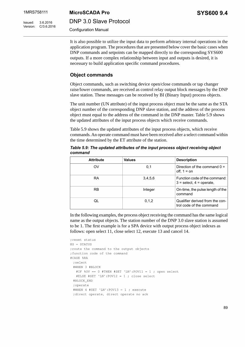
It is also possible to utilize the input data to perform arbitrary internal operations in theapplication program. The procedures that are presented below cover the basic cases whenDNP commands and setpoints can be mapped directly to the corresponding SYS600outputs. If a more complex relationship between input and outputs is desired, it isnecessary to build application specific command procedures.
Object commands
Object commands, such as switching device open/close commands or tap changerraise/lower commands, are received as control relay output block messages by the DNPslave station. These messages can be received by BI (Binary Input) process objects.
The unit number (UN attribute) of the input process object must be the same as the STAobject number of the corresponding DNP slave station, and the address of the processobject must equal to the address of the command in the DNP master. Table 5.9 showsthe updated attributes of the input process objects which receive commands.
Table 5.9 shows the updated attributes of the input process objects, which receivecommands. An operate command must have been received after a select command withinthe time determined by the ET attribute of the station.
Table 5.9: The updated attributes of the input process object receiving objectcommand
DescriptionValuesAttribute
Direction of the command 0 =off, 1 = on
0,1OV
Function code of the command:3 = select, 4 = operate,
3,4,5,6RA
On-time, the pulse length of thecommand
IntegerRB
Qualifier derived from the con-trol code of the command
0,1,2QL
In the following examples, the process object receiving the command has the same logicalname as the output objects. The station number of the DNP 3.0 slave station is assumedto be 1. The first example is for a SPA device with output process object indexes asfollows: open select 11, close select 12, execute 13 and cancel 14.
;reset status
@S = STATUS
;route the command to the output objects
;function code of the command
#CASE %RA
;select
#WHEN 3 #BLOCK
#IF %OV == 0 #THEN #SET ‘LN’:POV11 = 1 ; open select
#ELSE #SET ‘LN’:POV12 = 1 ; close select
#BLOCK_END
;operate
#WHEN 4 #SET ‘LN’:POV13 = 1 ; execute
;direct operate, direct operate no ack
89
SYS600 9.4MicroSCADA Pro
DNP 3.0 Slave Protocol
1MRS758111
3.6.2016Issued:C/3.6.2016Version:
Configuration Manual

#WHEN 5,6 #BLOCK
#IF %OV == 0 #THEN #SET ‘LN’:POV11 = 1 ; open select
#ELSE #SET ‘LN’:POV12 = 1 ; close select
#SET ‘LN’:POV13 = 1 ; execute
#BLOCK_END
#CASE_END
;confirm the command, if required
#IF %RA < 6 #THEN #BLOCK
#IF STATUS == 0 #THEN @CS = 0 ; report ok status
#ELSE @CS = 6 ; report hardware problems
#SET STA1:SCF = (%CS,'LN':POA'IX')
#BLOCK_END
The second example is for a RTU device with one output process object with index 13.This example also has a check mechanism for the station local/remote switch, which isin this example indicated by a double binary process object STA_LR:P10.
;reset status
@S = STATUS
;check the state of the station local remote switch
#IF STA_LR:POV10 == 2 #THEN #BLOCK ; remote
@LR_CS = 0 ; do not report outputs in local state
;route the command to the output objects
;function code of the command
#CASE %RA
;select
#WHEN 3 #SET ‘LN’:PSE13 = 1 ; select
;operate
#WHEN 4 #SET ‘LN’:POV13 = %OV ; execute
;direct operate, direct operate no ack
#WHEN 5,6 #BLOCK
#SET ‘LN’:PSE13 = 1 ; select
#SET ‘LN’:POV13 = %OV ; execute
#BLOCK_END
#CASE_END
#BLOCK_END
#ELSE #BLOCK ; local
@LR_CS = 128 ; report outputs in local state
#BLOCK_END
;confirm the command, if required
#IF %RA < 6 #THEN #BLOCK
#IF STATUS == 0 #THEN @CS = %LR_CS ; report ok status
#ELSE @CS = %LR_CS + 6 ; report hardware problems
#SET STA1:SCF = (%CS,'LN':POA'IX')
#BLOCK_END
Direct operate - no ack type commands are not confirmed byusing the CF attribute.
90
1MRS758111MicroSCADA ProSYS600 9.4DNP 3.0 Slave ProtocolConfiguration Manual

Analog setpoints
Analog output block messages from the DNP master can be received by AI (AnalogInput) process objects.
The unit number (UN attribute) of the input process object must be the same as the STAobject number of the corresponding DNP slave station, and the address of the processobject must be equal to the address of the command in the DNP master.
The attributes in the following Table 5.10 of the input process objects receiving thecommands are updated.
Table 5.10: The updated attributes of the input process objects receiving setpointcommands
DescriptionValuesAttribute
Value, range depends on the VariationReal or IntegerOV
Function code of the command: 3 = se-lect, 4 = operate, 5 = direct operate, 6=direct operate - no ack
3,4,5,6RA
Control status of the command0...255RB
5.5.2.6 Command procedures for application and system commands
Application and system commands, such as restart commands, can be received by anANSI bit stream process object. The object's unit number is equal to the station numberof the DNP 3.0 slave station. The object's address is equal to the configured value of theCA attribute of the DNP 3.0 slave station. The NET unit sends messages to the processobject as transparent data. The messages must be interpreted using SCIL statements.
The following example provides the SCIL code needed to initiate the cold restart andwarm restart commands, the function codes 13 and 14 respectively.
;unpack the system command
@SYS_CMD = UNPACK_STR(%BS,8)
;application control function code of the command
@FUNC_CODE = %SYS_CMD(2)
;perform the command based on the function code
#CASE %FUNC_CODE
;cold restart
#WHEN 13 #BLOCK
;code needed in cold restart
#BLOCK_END
;warm restart
#WHEN 14 #BLOCK
;code needed in cold restart
#BLOCK_END
#CASE_END
91
SYS600 9.4MicroSCADA Pro
DNP 3.0 Slave Protocol
1MRS758111
3.6.2016Issued:C/3.6.2016Version:
Configuration Manual

The following actions should be taken when one of the restart commands is received.Usually, these commands vary from one application to another. The cold restart commandis especially problematic since the base system computer cannot be switched off usingSCIL. Listed below are some actions that can be taken with these commands.
• Restart PC-NET by setting LINn:BLT to "NONE" and after a pause back to"INTEGRATED". After this, the lines and stations must be re-created and the NETdatabase re-initialized.
• Reset the message queues in the NET unit by using the RS attribute of the DNP 3.0slave station.
• Send an interrogation command to all the process devices. This updates the processdatabase, and thus the NET database as well, all the way from the process devices.
• Re-initialize the NET internal database by using the command procedure presentedearlier in this document.
5.6 Signal engineering
The term signal engineering here means the engineering needed to establishcommunication to an NCC using the DNP protocol. The signal engineering in COM500iis made using the signal X-reference tool after the system configuration is completedand the process database for the related to process devices is ready. The signal engineeringprocess has been described in detail in COM500i Users Guide manual of the SYS600product. The principal sequence for the signal engineering is:
1. Make a list of all signals that are to be transferred between the master and the slave.Include the data object type, variation and address of the static data object. If anevent is to be sent, also include data object type, variation, class and delta of theevent.
2. Determine the communication mode, i.e. whether polling or unsolicited messagesare used for sending data to the master, based on the information about the behaviorof the master system.
3. Define the NCCs, communication mode and the cross-reference data using the SignalX-references tool of COM500i.
4. Test each signal.
5.7 Status codes
The status codes for the DNP 3.0 Slave protocol are defined in the SYS600 Status Codesmanual. Some typical reasons for some of the status codes are also given.
Status codes are sent as system messages which can be received by analog input projectobjects with a unit number (UN) 0 and an object address (OA) as determined by the MIattribute of the line or station, or alternatively, they are returned as a response to a SCILcommand accessing a DNP station object.
92
1MRS758111MicroSCADA ProSYS600 9.4DNP 3.0 Slave ProtocolConfiguration Manual

5.8 Device profile
Device profile (Subset 2)
Table 5.11: The device profile that describes the implementation of the DNP 3.0 slave protocol in SYS600,Subset 2: the default subset.DNP 3.0DEVICE PROFILE DOCUMENT
Vendor Name: ABB Oy Substation Automation Products
Device Name: MicroSCADA revision 9.4
Device Function:Highest DNP Level Supported:[ ] MasterFor Requests: Subset Level 2[x] SlaveFor Responses: Subset Level 2
Maximum Application Fragment Size (octets):Maximum Data Link Frame Size (octets):Transmitted: 255…2048, STA attribute MLTransmitted: 58…292, line attribute MLReceived : 2048Received: (must be 292)
Maximum Application Layer Re-tries:Maximum Data Link Re-tries:[x] None[ ] None[ ] Configurable[ ] Fixed at _______________________
[x] Configurable, range 0 to 10, line attribute EN
Requires Data Link Layer Confirmation:[ ] Never[ ] Always[ ] Sometimes If 'Sometimes', when?_____________[x] Configurable, line attribute LA
Requires Application Layer Confirmation:[ ] Never[ ] Always (not recommended)[ ] When reporting Event Data (Slave devices only)[ ] When sending multi-fragment responses (Slave devices only)[ ] Sometimes. If 'Sometimes', when?____________[x] Configurable, station attribute PC
Timeouts while waiting for:
Data Link Confirm[ ] None [ ] Variable [ ] Fixed at __[x] Configurable, line attribute HTComplete Appl. Fragment[ ] None [ ] Variable [ ] Fixed at __[x] Configurable, station attribute TTApplication Confirm[ ] None [ ] Variable [ ] Fixed at __[x] Configurable, station attribute CTComplete Appl. Response[x ] None [ ] Variable [ ] Fixed at __[] Configurable
Others:Retransmission after a collision, STA attribute XR (randomdelay if collision detection used).Complete data link frame: line attribute TI.
93
SYS600 9.4MicroSCADA Pro
DNP 3.0 Slave Protocol
1MRS758111
3.6.2016Issued:C/3.6.2016Version:
Configuration Manual

Sends/Executes Control Operations:
WRITE Binary Outputs[x] Never [ ] Sometimes[ ] Always [ ] ConfigurableSELECT/OPERATE[ ] Never [ ] Sometimes[x] Always [ ] ConfigurableDIRECT OPERATE[ ] Never [ ] Sometimes[x] Always [ ] ConfigurableDIRECT OPERATE - NO ACK[ ] Never [ ] Sometimes[x] Always [ ] ConfigurableCount > 1[x] Never [ ] Sometimes[ ] Always [ ] ConfigurablePulse On[ ] Never [ ] Sometimes[x] Always [ ] ConfigurablePulse Off[ ] Never [ ] Sometimes[x] Always [ ] ConfigurableLatch On[ ] Never [ ] Sometimes[x] Always [ ] ConfigurableLatch Off[ ] Never [ ] Sometimes[x] Always [ ] ConfigurableQueue[x] Never [ ] Sometimes[ ] Always [ ] ConfigurableClear Queue[x] Never [ ] Sometimes[ ] Always [ ] Configurable
FILL OUT THE FOLLOWING ITEMS FOR SLAVE DEVICES ONLY:
Reports time-tagged Binary Input Change Events whenno specific variation requested:
Reports Binary Input Change Events when no specificvariation requested:
[ ] Never[ ] Never[ ] Binary Input Change With Time[ ] Only time-tagged[ ] Binary Input Change With Relative Time[ ] Only non-time-tagged[x] Configurable, depends on data point initialization[x] Configurable to send one or the other, depends on data
point init
Sends Static Data in Unsolicited Responses:Sends Unsolicited Responses:[x] Never[ ] Never[ ] When Device Restarts (depends on data point initialization)[x] Configurable, depends on data point initialization[ ] When Status Flags Change (depends on data point initializ-ation)
[ ] Only certain objects[ ] Sometimes (attach explanation)[ ] ENABLE/DISABLE UNSOLICITED function codes supported
Counters Roll Over at:Default Counter Object/ Variation:[ ] No Counters Reported[ ] No Counters Reported[ ] Configurable (attach explanation)[x] Configurable, depends on data point initialization[ ] 16 bit[ ] Default Object________________________[x] 32 Bits, roll-over bits not set[ ] Default Variation______________________[ ] Other Value__________________________________[ ] Point-by-point list attached[ ] Point-by-point list attached
94
1MRS758111MicroSCADA ProSYS600 9.4DNP 3.0 Slave ProtocolConfiguration Manual

Sends Multi-Fragment Responses:
[ ] No[x] Yes
Supported function codes (Subset 2)
Table 5.12: Supported function codesSupportedDESCRIPTIONFUNCTIONCODE
TransferFunctionCodes
YesMessage fragment confirmationConfirm0No Response
YesRequest objects from outstationRead1Respond with requested objects
YesStore the specified objects to outstationWrite2Respond with status of the operation
ControlFunctionCodes
YesSelect the output point of outstationSelect3Respond with status of control point
YesSet the output that has previously been selectedOperate4Respond with status of control point
YesSet the output directlyDirect operate5Respond with status of control point
YesSet the output directlyDirect operate6No response- no ack
FreezeFunctionCodes
YesCopy the specified objects to freeze bufferImmediate Freeze7Respond with status of operation
YesCopy the specified objects to freeze bufferImmediate Freeze8No response- no ack
YesCopy the specified objects to freeze buffer and clear objectsFreeze and Clear9Respond with status of operation
YesCopy the specified objects to freeze buffer and clear objectsFreeze and Clear10No response- no ack
NoCopy the specified objects to freeze buffer at specified timeFreeze with time11Respond with status of operation
NoCopy the specified objects to freeze buffer at specified timeFreeze with time12No response- no ack
95
SYS600 9.4MicroSCADA Pro
DNP 3.0 Slave Protocol
1MRS758111
3.6.2016Issued:C/3.6.2016Version:
Configuration Manual

SupportedDESCRIPTIONFUNCTIONCODE
Applica-tion Con-trol Func-
tionCodes
YesPerform the desired reset sequenceCold Restart13Respond with a time object
YesPerform the desired partial reset operationWarm Restart14Respond with a time object
NoInitialize the specified data to defaultInitialize Data to De-faults
15Respond with the status of operation
NoPrepare the specified application to runInitialize Application16Respond with the status of operation
NoStart the specified application to runStart Application17Respond with the status of operation
NoStop the specified application to runStop Application18Respond with the status of operation
Configura-tion Func-
tionCodes
NoSave the configurationSave configuration19Respond with the status of operation
NoEnable Unsolicited MessagesEnable UnsolicitedMessages
20Respond with the status of operation
NoDisable Unsolicited MessagesDisable UnsolicitedMessages
21Respond with the status of operation
NoAssign specified objects to a classAssign Class22Respond with the status of operation
Time Syn-chroniza-tion Func-
tionCodes
YesPerform propagation delay measurementDelay Measurement23
YesUsed in a network application to allow the Master station andthe Out station to record their time at the same instant
Record current time24
Authentic-ation Re-quest
FunctionCodes
YesAuthentication RequestAuthentication Request32
NoAuthentication ErrorAuthentication Error33
96
1MRS758111MicroSCADA ProSYS600 9.4DNP 3.0 Slave ProtocolConfiguration Manual

SupportedDESCRIPTIONFUNCTIONCODE
ResponseFunctionCodes
YesMessage fragment confirmationConfirm0
YesResponse to requested messageResponse129
YesSpontaneous message without requestUnsolicited Message130
YesAuthentication ResponseAuthentication Re-sponse
131
Supported objects (Subset 2)
Table 5.13: Supported objectsRESPONSE(master must parse)
REQUEST(slave must parse)
OBJECT
Qual Codes(hex)
Func CodesQual Codes(hex)
Func CodesDescriptionVarObj
061Binary Input - All Variations01
00, 01129, 13000,01,061Binary Input11
00, 01129, 13000,01,061Binary Input with Status21
06,07,081Binary Input Change - All Variations02
17, 28129, 13006,07,081Binary Input Change without Time12
17, 28129, 13006,07,081Binary Input Change with Time22
17, 28129, 13006,07,081Binary Input Change with Relative Time32
061Double bit Input - All Variations03
00, 01129, 13000,01,061Double bit input13
00, 01129, 13000,01,061Double bit input with status23
06, 07,081Double bit input change – All variations04
17, 28129, 13006,07,081Double bit input change event14
17, 28129, 13006,07,081Double bit input change event with time24
17, 28129, 13006,07,081Double bit input change event with relative time34
061Binary Output - All Variations010
Binary Output110
00, 01129, 13000,01,061Binary Output Status210
Control Block - All Variations012
echo of re-quest + status
12917, 27,283, 4, 5, 6Control Relay Output Block112
Pattern Control Block212
Pattern Mask312
061, 7, 8, 9, 10Binary Counter - All Variations020
97
SYS600 9.4MicroSCADA Pro
DNP 3.0 Slave Protocol
1MRS758111
3.6.2016Issued:C/3.6.2016Version:
Configuration Manual

RESPONSE(master must parse)
REQUEST(slave must parse)
OBJECT
Qual Codes(hex)
Func CodesQual Codes(hex)
Func CodesDescriptionVarObj
00, 01129, 13000,01,06132-Bit Binary Counter120
00, 01129, 13016-Bit Binary Counter220
00, 01129, 13032-Bit Delta Counter320
00, 01129, 13016-Bit Binary Counter420
00, 01129, 13000,01,06132-Bit Binary Counter without Flag520
00, 01129, 13016-Bit Binary Counter without Flag620
00, 01129, 13032-Bit Delta Counter without Flag720
00, 01129, 13016-Bit Delta Counter without Flag820
061Frozen Counter - All Variations021
00, 01129, 13032-Bit Frozen Counter121
00, 01129, 13016-Bit Frozen Counter221
32-Bit Frozen Delta Counter321
16-Bit Frozen Delta Counter421
32-Bit Frozen Counter with Time of Freeze521
16-Bit Frozen Counter with Time of Freeze621
32-Bit Frozen Delta Counter with Time ofFreeze
721
16-Bit Frozen Delta Counter with Time ofFreeze
821
00, 01129, 13032-Bit Frozen Counter without Flag921
00, 01129, 13016-Bit Frozen Counter without Flag1021
32-Bit Frozen Delta Counter without Flag1121
16-Bit Frozen Delta Counter without Flag1221
06,07,081Counter Change Event - All Variations022
17, 28129, 13032-Bit Counter Change Event without Time122
17, 28129, 13016-Bit Counter Change Event without Time222
32-Bit Delta Counter Change Event withoutTime
322
16-Bit Delta Counter Change Event withoutTime
422
32-Bit Counter Change Event with Time522
16-Bit Counter Change Event with Time622
32-Bit Delta Counter Change Event with Time722
16-Bit Delta Counter Change Event with Time822
Frozen Counter Event - All Variations023
98
1MRS758111MicroSCADA ProSYS600 9.4DNP 3.0 Slave ProtocolConfiguration Manual

RESPONSE(master must parse)
REQUEST(slave must parse)
OBJECT
Qual Codes(hex)
Func CodesQual Codes(hex)
Func CodesDescriptionVarObj
32-Bit Frozen Counter Event without Time123
16-Bit Frozen Counter Event without Time223
32-Bit Frozen Delta Counter Event without Time323
16-Bit Frozen Delta Counter Event without Time423
32-Bit Frozen Counter Event with Time523
16-Bit Frozen Counter Event with Time623
32-Bit Frozen Delta Counter Event with Time723
16-Bit Frozen Delta Counter Event with Time823
061Analog Input - All Variations030
00, 01129, 13032-Bit Analog Input130
00, 01129, 13000,01,06116-Bit Analog Input230
00, 01129, 13032-Bit Analog Input without Flag330
00, 01129, 13000,01,06116-Bit Analog Input without Flag430
Frozen Analog Input - All Variations031
32-Bit Frozen Analog Input131
16-Bit Frozen Analog Input231
32-Bit Frozen Analog Input with Time of Freeze331
16-Bit Frozen Analog Input with Time of Freeze431
32-Bit Frozen Analog Input without Flag531
16-Bit Frozen Analog Input without Flag631
06,07,081Analog Change Event - All Variations032
17,28129,13032-Bit Analog Change Event without Time132
17,28129,13016-Bit Analog Change Event without Time232
32-Bit Analog Change Event with Time332
16-Bit Analog Change Event with Time432
Frozen Analog Event - All Variations033
32-Bit Frozen Analog Event without Time133
16-Bit Frozen Analog Event without Time233
32-Bit Frozen Analog Event with Time333
16-Bit Frozen Analog Event with Time433
061Analog Output Status - All Variations040
32-Bit Analog Output Status140
00, 01129, 13016-Bit Analog Output Status240
Analog Output Block - All Variations041
99
SYS600 9.4MicroSCADA Pro
DNP 3.0 Slave Protocol
1MRS758111
3.6.2016Issued:C/3.6.2016Version:
Configuration Manual

RESPONSE(master must parse)
REQUEST(slave must parse)
OBJECT
Qual Codes(hex)
Func CodesQual Codes(hex)
Func CodesDescriptionVarObj
32-Bit Analog Output Block141
echo of re-quest + status
12917, 283, 4, 5, 616-Bit Analog Output Block241
Time and Date - All Variations050
062Time and Date15007
quantity = 1
Time and Date with Interval250
Time and Date CTO - All Variations051
07, quantity=1129, 130Time and Date CTO151
07, quantity=1129, 130Unsynchronized Time and Date CTO251
Time Delay - All Variations052
07, quantity=1129Time Delay Coarse152
07, quantity=1129Time Delay Fine252
060
061Class 0 Data160
06,07,081Class 1 Data260
06,07,081Class 2 Data360
06,07,081Class 3 Data460
File Identifier170
All1Internal Indications18000,index=72
Storage Object181
Device Profile182
Private Registration Object183
Private Registration Object Descriptor283
Application Identifier190
Short Floating Point1100
Long Floating Point2100
Extended Floating Point3100
Small Packed Binary-Coded Decimal1101
Medium Packed Binary-Coded Decimal2101
Large Packed Binary-Coded Decimal3101
13No Object
23No Object
100
1MRS758111MicroSCADA ProSYS600 9.4DNP 3.0 Slave ProtocolConfiguration Manual

Device profile (Subset 3)
Table 5.14: The device profile that describes the implementation of the DNP 3.0 slave protocol in SYS600,Subset 3DNP 3.0DEVICE PROFILE DOCUMENT
Vendor Name: ABB Oy Substation Automation Products
Device Name: MicroSCADA revision 9.4
Device Function:Highest DNP Level Supported:[ ] MasterFor Requests: Subset Level 3[x] SlaveFor Responses: Subset Level 3
Maximum Application Fragment Size (octets):Maximum Data Link Frame Size (octets):Transmitted: 255…2048, STA attribute MLTransmitted: 58…292, line attribute MLReceived : 2048Received: (must be 292)
Maximum Application Layer Re-tries:Maximum Data Link Re-tries:[x] None[ ] None[ ] Configurable[ ] Fixed at _______________________
[x] Configurable, range 0 to 10, line attribute EN
Requires Data Link Layer Confirmation:[ ] Never[ ] Always[ ] Sometimes If 'Sometimes', when?_____________[x] Configurable, line attribute LA
Requires Application Layer Confirmation:[ ] Never[ ] Always (not recommended)[ ] When reporting Event Data (Slave devices only)[ ] When sending multi-fragment responses (Slave devices only)[ ] Sometimes. If 'Sometimes', when?____________[x] Configurable, station attribute PC
Timeouts while waiting for:
Data Link Confirm[ ] None [ ] Variable [ ] Fixed at __[x] Configurable, line attribute HTComplete Appl. Fragment[ ] None [ ] Variable [ ] Fixed at __[x] Configurable, station attribute TTApplication Confirm[ ] None [ ] Variable [ ] Fixed at __[x] Configurable, station attribute CTComplete Appl. Response[x ] None [ ] Variable [ ] Fixed at __[] Configurable
Others:Retransmission after a collision, STA attribute XR (randomdelay if collision detection used).Complete data link frame: line attribute TI.
Sends/Executes Control Operations:
101
SYS600 9.4MicroSCADA Pro
DNP 3.0 Slave Protocol
1MRS758111
3.6.2016Issued:C/3.6.2016Version:
Configuration Manual
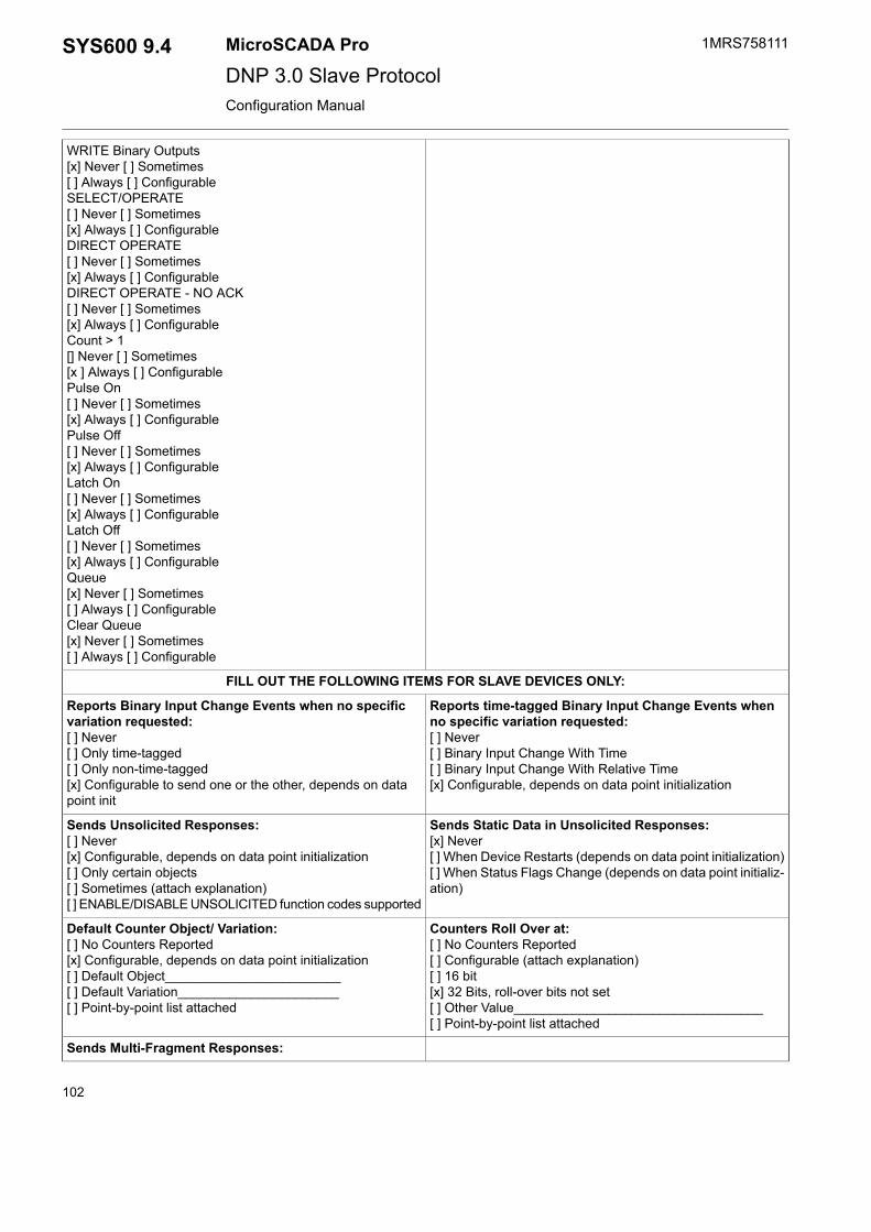
WRITE Binary Outputs[x] Never [ ] Sometimes[ ] Always [ ] ConfigurableSELECT/OPERATE[ ] Never [ ] Sometimes[x] Always [ ] ConfigurableDIRECT OPERATE[ ] Never [ ] Sometimes[x] Always [ ] ConfigurableDIRECT OPERATE - NO ACK[ ] Never [ ] Sometimes[x] Always [ ] ConfigurableCount > 1[] Never [ ] Sometimes[x ] Always [ ] ConfigurablePulse On[ ] Never [ ] Sometimes[x] Always [ ] ConfigurablePulse Off[ ] Never [ ] Sometimes[x] Always [ ] ConfigurableLatch On[ ] Never [ ] Sometimes[x] Always [ ] ConfigurableLatch Off[ ] Never [ ] Sometimes[x] Always [ ] ConfigurableQueue[x] Never [ ] Sometimes[ ] Always [ ] ConfigurableClear Queue[x] Never [ ] Sometimes[ ] Always [ ] Configurable
FILL OUT THE FOLLOWING ITEMS FOR SLAVE DEVICES ONLY:
Reports time-tagged Binary Input Change Events whenno specific variation requested:
Reports Binary Input Change Events when no specificvariation requested:
[ ] Never[ ] Never[ ] Binary Input Change With Time[ ] Only time-tagged[ ] Binary Input Change With Relative Time[ ] Only non-time-tagged[x] Configurable, depends on data point initialization[x] Configurable to send one or the other, depends on data
point init
Sends Static Data in Unsolicited Responses:Sends Unsolicited Responses:[x] Never[ ] Never[ ] When Device Restarts (depends on data point initialization)[x] Configurable, depends on data point initialization[ ] When Status Flags Change (depends on data point initializ-ation)
[ ] Only certain objects[ ] Sometimes (attach explanation)[ ] ENABLE/DISABLE UNSOLICITED function codes supported
Counters Roll Over at:Default Counter Object/ Variation:[ ] No Counters Reported[ ] No Counters Reported[ ] Configurable (attach explanation)[x] Configurable, depends on data point initialization[ ] 16 bit[ ] Default Object________________________[x] 32 Bits, roll-over bits not set[ ] Default Variation______________________[ ] Other Value__________________________________[ ] Point-by-point list attached[ ] Point-by-point list attached
Sends Multi-Fragment Responses:
102
1MRS758111MicroSCADA ProSYS600 9.4DNP 3.0 Slave ProtocolConfiguration Manual

[ ] No[x] Yes
Supported function codes (Subset 3)
Table 5.15: Supported function codesSupportedDESCRIPTIONFUNCTIONCODE
TransferFunctionCodes
YesMessage fragment confirmationConfirm0No Response
YesRequest objects from outstationRead1Respond with requested objects
YesStore the specified objects to outstationWrite2Respond with status of the operation
ControlFunctionCodes
YesSelect the output point of outstationSelect3Respond with status of control point
YesSet the output that has previously been selectedOperate4Respond with status of control point
YesSet the output directlyDirect operate5Respond with status of control point
YesSet the output directlyDirect operate6No response- no ack
FreezeFunctionCodes
YesCopy the specified objects to freeze bufferImmediate Freeze7Respond with status of operation
YesCopy the specified objects to freeze bufferImmediate Freeze8No response- no ack
YesCopy the specified objects to freeze buffer and clear objectsFreeze and Clear9Respond with status of operation
YesCopy the specified objects to freeze buffer and clear objectsFreeze and Clear10No response- no ack
NoCopy the specified objects to freeze buffer at specified timeFreeze with time11Respond with status of operation
NoCopy the specified objects to freeze buffer at specified timeFreeze with time12No response- no ack
Applica-tion Con-trol Func-
tionCodes
103
SYS600 9.4MicroSCADA Pro
DNP 3.0 Slave Protocol
1MRS758111
3.6.2016Issued:C/3.6.2016Version:
Configuration Manual

SupportedDESCRIPTIONFUNCTIONCODE
YesPerform the desired reset sequenceCold Restart13Respond with a time object
YesPerform the desired partial reset operationWarm Restart14Respond with a time object
NoInitialize the specified data to defaultInitialize Data to De-faults
15Respond with the status of operation
NoPrepare the specified application to runInitialize Application16Respond with the status of operation
NoStart the specified application to runStart Application17Respond with the status of operation
NoStop the specified application to runStop Application18Respond with the status of operation
Configura-tion Func-
tionCodes
NoSave the configurationSave configuration19Respond with the status of operation
YesEnable Unsolicited MessagesEnable UnsolicitedMessages
20Respond with the status of operation
YesDisable Unsolicited MessagesDisable UnsolicitedMessages
21Respond with the status of operation
YesAssign specified objects to a classAssign Class22Respond with the status of operation
Time Syn-chroniza-tion Func-
tionCodes
YesPerform propagation delay measurementDelay Measurement23
YesUsed in a network application to allow the Master station andthe Out station to record their time at the same instant
Record current time24
Authentic-ation Re-quest
FunctionCodes
YesAuthentication RequestAuthentication Request32
NoAuthentication ErrorAuthentication Error33
ResponseFunctionCodes
YesMessage fragment confirmationConfirm0
YesResponse to requested messageResponse129
YesSpontaneous message without requestUnsolicited Message130
104
1MRS758111MicroSCADA ProSYS600 9.4DNP 3.0 Slave ProtocolConfiguration Manual

SupportedDESCRIPTIONFUNCTIONCODE
YesAuthentication ResponseAuthentication Re-sponse
131
Supported objects (Subset 3)
Table 5.16: Supported objectsREQUEST
(slave must parse)OB-JECT
Qual Codes(hex)
Func CodesQual Codes(hex)
Func CodesDescriptionVarObj
00,01,061,22Binary Input - All Variations01
00, 01129, 13000,01,061Binary Input11
00, 01129, 13000,01,061Binary Input with Status21
06,07,081Binary Input Change - All Variations02
17, 28129, 13006,07,081Binary Input Change without Time12
17, 28129, 13006,07,081Binary Input Change with Time22
17, 28129, 13006,07,081Binary Input Change with Relative Time32
00, 01, 061,22Double bit Input - All Variations03
00, 01129, 13000,01,061Double bit input13
00, 01129, 13000,01,061Double bit input with status23
06, 07,081Double bit input change – All variations04
17, 28129, 13006,07,081Double bit input change event14
17, 28129, 13006,07,081Double bit input change event with time24
17, 28129, 13006,07,081Double bit input change event with relat-ive time
34
061Binary Output - All Variations010
Binary Output110
00, 01129, 13000,01,061Binary Output Status210
Control Block - All Variations012
echo of request12917, 27,283, 4, 5, 6Control Relay Output Block112
echo of request12917, 285, 6Pattern Control Block212
echo of request12900,015, 6Pattern Mask312
00,01,061, 7, 8, 9, 10, 22Binary Counter - All Variations020
00, 01129, 13000,01,06132-Bit Binary Counter120
00, 01129, 13000,01,06116-Bit Binary Counter220
00, 01129, 13000,01,06132-Bit Delta Counter320
00, 01129, 13000,01,06116-Bit Binary Counter420
00, 01129, 13000,01,06132-Bit Binary Counter without Flag520
00, 01129, 13000,01,06116-Bit Binary Counter without Flag620
105
SYS600 9.4MicroSCADA Pro
DNP 3.0 Slave Protocol
1MRS758111
3.6.2016Issued:C/3.6.2016Version:
Configuration Manual

REQUEST(slave must parse)
OB-JECT
00, 01129, 13000,01,06132-Bit Delta Counter without Flag720
00, 01129, 13000,01,06116-Bit Delta Counter without Flag820
00,01,061,22Frozen Counter - All Variations021
00, 01129, 13000,01,06132-Bit Frozen Counter121
00, 01129, 13000,01,06116-Bit Frozen Counter221
00, 01129, 13000,01,06132-Bit Frozen Delta Counter321
00, 01129, 13000,01,06116-Bit Frozen Delta Counter421
32-Bit Frozen Counter with Time ofFreeze
521
16-Bit Frozen Counter with Time ofFreeze
621
32-Bit Frozen Delta Counter with Timeof Freeze
721
16-Bit Frozen Delta Counter with Timeof Freeze
821
00, 01129, 13000,01,06132-Bit Frozen Counter without Flag921
00, 01129, 13000,01,06116-Bit Frozen Counter without Flag1021
32-Bit Frozen Delta Counter without Flag1121
16-Bit Frozen Delta Counter without Flag1221
06,07,081Counter Change Event - All Variations022
17, 28129, 13006,07,08132-Bit Counter Change Event withoutTime
122
17, 28129, 13006,07,08116-Bit Counter Change Event withoutTime
222
17, 28129, 13006,07,08132-Bit Delta Counter Change Eventwithout Time
322
17, 28129, 13006,07,08116-Bit Delta Counter Change Eventwithout Time
422
32-Bit Counter Change Event with Time522
16-Bit Counter Change Event with Time622
32-Bit Delta Counter Change Event withTime
722
16-Bit Delta Counter Change Event withTime
822
06,07,081Frozen Counter Event - All Variations023
17, 28129, 13006,07,08132-Bit Frozen Counter Event withoutTime
123
17, 28129, 13006,07,08116-Bit Frozen Counter Event withoutTime
223
106
1MRS758111MicroSCADA ProSYS600 9.4DNP 3.0 Slave ProtocolConfiguration Manual

REQUEST(slave must parse)
OB-JECT
17, 28129, 13006,07,08132-Bit Frozen Delta Counter Eventwithout Time
323
17, 28129, 13006,07,08116-Bit Frozen Delta Counter Eventwithout Time
423
32-Bit Frozen Counter Event with Time523
16-Bit Frozen Counter Event with Time623
32-Bit Frozen Delta Counter Event withTime
723
16-Bit Frozen Delta Counter Event withTime
823
00,01,061,22Analog Input - All Variations030
00, 01129, 13000,01,06132-Bit Analog Input130
00, 01129, 13000,01,06116-Bit Analog Input230
00, 01129, 13000,01,06132-Bit Analog Input without Flag330
00, 01129, 13000,01,06116-Bit Analog Input without Flag430
00, 01129, 13000,01,061Analog Input - Single-Precision, Floating-Point with Flag
530
Frozen Analog Input - All Variations031
32-Bit Frozen Analog Input131
16-Bit Frozen Analog Input231
32-Bit Frozen Analog Input with Time ofFreeze
331
16-Bit Frozen Analog Input with Time ofFreeze
431
32-Bit Frozen Analog Input without Flag531
16-Bit Frozen Analog Input without Flag631
06,07,081Analog Change Event - All Variations032
17,28129,13006,07,08132-Bit Analog Change Event withoutTime
132
17,28129,13006,07,08116-Bit Analog Change Event withoutTime
232
17,28129,13006,07,08132-Bit Analog Change Event with Time332
17,28129,13006,07,08116-Bit Analog Change Event with Time432
17,28129,13006,07,081Analog Change Event - Single-Precision,Floating-Point without Time
532
17,28129,13006,07,081Analog Change Event - Single-Precision,Floating-Point with Time
732
Frozen Analog Event - All Variations033
32-Bit Frozen Analog Event without Time133
16-Bit Frozen Analog Event without Time233
107
SYS600 9.4MicroSCADA Pro
DNP 3.0 Slave Protocol
1MRS758111
3.6.2016Issued:C/3.6.2016Version:
Configuration Manual

REQUEST(slave must parse)
OB-JECT
32-Bit Frozen Analog Event with Time333
16-Bit Frozen Analog Event with Time433
00,01,061Analog Output Status - All Variations040
00, 01129, 13000,01,06132-Bit Analog Output Status140
00, 01129, 13000,01,06116-Bit Analog Output Status240
00, 01129, 13000,01,061Analog Output Status - Single-Precision,Floating-Point with Flag
340
echo of request12917, 283, 4, 5, 632-Bit Analog Output Block141
echo of request12917, 283, 4, 5, 616-Bit Analog Output Block241
echo of request12917, 283, 4, 5, 6Analog output - Single-Precision, Float-ing-Point
341
Time and Date - All Variations050
072 (see 4.14)Time and Date150quantity = 1
07129071quantity = 1quantity = 1
Time and Date with Interval250
Time and Date CTO - All Variations051
07, quantity=1129, 130Time and Date CTO151
07, quantity=1129, 130Unsynchronized Time and Date CTO251
Time Delay - All Variations052
07, quantity=1129Time Delay Coarse152
07, quantity=1129Time Delay Fine252
060
061Class 0 Data160
06,07,081Class 1 Data2600620, 21, 22
06,07,081Class 2 Data3600620, 21, 22
06,07,081Class 3 Data4600620, 21, 22
File Identifier170
00,011Internal Indications18000 index = 72
Storage Object181
Device Profile182
Private Registration Object183
Private Registration Object Descriptor283
108
1MRS758111MicroSCADA ProSYS600 9.4DNP 3.0 Slave ProtocolConfiguration Manual

REQUEST(slave must parse)
OB-JECT
Application Identifier190
Short Floating Point1100
Long Floating Point2100
Extended Floating Point3100
Small Packed Binary-Coded Decimal1101
Medium Packed Binary-Coded Decimal2101
Large Packed Binary-Coded Decimal3101
13No Object
23No Object
TCP/UDP additions for LAN/WAN network
SYS600 LAN/WAN DNP uses the default IP address provided by the operating system.
A created DNP Slave line reserves a port number
2501+linenumber
for its internal use.
In TCP/IP mode (connection-oriented), the connection is established to port
20000 (default)
of the slave device. The local address the line is listening to is defined with the lineattribute LD. The port number can be configured using an option in the LD attribute.Only one connection to each master station is established at any one time. The IP addressof the master is configured with the IA and AI attributes of the station object.
In UDP/IP mode (connectionless) all data is sent and received through port
20000
The slave device must receive messages from this port only. All messages that are sentby the slave device must be sent to this port of the master. The IP address of the slaveis configured with the IA attribute of the station object. The multidrop configurationrequires redefinition of local ports though all the communication goes through port20000. This configuration has been explained in the description of the IA attribute.
Secure authentication
DNP 3.0 in SYS600 supports secure authentication versions v2 and v5. For secureauthentication version v2, the supported message types are of object type 120(Authentication), variations 1-7 and 9. For secure authentication version v5, the supportedmessage types are of object type 120 (Authentication), variations 1-7 and 9-15. Thefunction codes used with these object types are 32 = Authentication Request and 131 =Authentication Response. The supported qualifiers are fixed in DNP 3.0 standard.
109
SYS600 9.4MicroSCADA Pro
DNP 3.0 Slave Protocol
1MRS758111
3.6.2016Issued:C/3.6.2016Version:
Configuration Manual

Example topologies:
LAN/WAN
Network Control CenterDNP 3.0 Master (TCP)Station 1Station 2Station 3
MicroSCADA
IP 62.236.145.130
Station 1 (COM500)DNP Slave Line
IP-address62.236.145.119
Line SD="TCP";connection oriented;mode, listen port 20000Station 1 IA="62.236.145.130"
Station 2 (IEC, RTU..)
IP-address62.236.145.120Listens port 20000
Station 2 (IEC, RTU..)
IP-address62.236.145.121Listens port 20000
RTU RTU RTU RTU
RTU RTU RTU RTU
Figure 5.3: SYS600 (COM500i) as DNP3.0 TCP slave in multidrop environment
110
1MRS758111MicroSCADA ProSYS600 9.4DNP 3.0 Slave ProtocolConfiguration Manual

LAN/WAN
Network Control CenterDNP 3.0 Master (UDP)Station 1Station 2Station 3
MicroSCADA
IP 62.236.145.130
Station 1 (COM500)DNP Slave Line
IP-address62.236.145.119
Line SD="UDP";connectionless mode;uses port 20000Station 1 IA="62.236.145.130"
Station 2 (IEC, RTU..)
IP-address62.236.145.120Uses port 20000
Station 2 (IEC, RTU..)
IP-address62.236.145.121Uses port 20000
RTU RTU RTU RTU
RTU RTU RTU RTU
Figure 5.4: SYS600 (COM500i) as DNP3.0 UDP slave in multidrop environment
111
SYS600 9.4MicroSCADA Pro
DNP 3.0 Slave Protocol
1MRS758111
3.6.2016Issued:C/3.6.2016Version:
Configuration Manual


Appendix A Configuration examples
DNP Slave in TCP mode@NET=4
@STA=1
@LINE=1
#SET NET'NET':SPO'LINE'=35
#SET NET'NET':SDV(30)=('STA','LINE')
#SET NET'NET':SSD'LINE'="TCP"
#SET NET'NET':SEN'LINE'=3
#SET NET'NET':SMS'LINE'='NET'
#SET NET'NET':SPD'LINE'=0
#SET NET'NET':SLK'LINE'=15
#SET NET'NET':STI'LINE'=3
#SET NET'NET':SPS'LINE'=50
#SET NET'NET':SLA'LINE'=0
#SET NET'NET':STW'LINE'=0
#SET NET'NET':SIU'LINE'=1
#SET NET'NET':SIU'LINE'=0
#SET STA'STA':SAL=1
#SET STA'STA':SDR=1
#SET STA'STA':SIA="192.168.1.119"
#SET STA'STA':SSA='STA'
#SET STA'STA':SMA=10
#SET STA'STA':STT=25
#SET STA'STA':SCT=10
#SET STA'STA':SRT=30
#SET STA'STA':SPC=1
#SET STA'STA':SRM=4
#SET STA'STA':SIU=1
#SET NET'NET':SIU'LINE'=1
DNP Slave in UDP mode@NET=4
@STA=1
@LINE=1
#SET NET'NET':SPO'LINE'=35
#SET NET'NET':SDV(30)=('STA','LINE')
#SET NET'NET':SSD'LINE'="UDP"
#SET NET'NET':SEN'LINE'=3
#SET NET'NET':SMS'LINE'='NET'
#SET NET'NET':SPD'LINE'=0
#SET NET'NET':SLK'LINE'=15
#SET NET'NET':STI'LINE'=3
#SET NET'NET':SPS'LINE'=50
#SET NET'NET':SLA'LINE'=0
#SET NET'NET':STW'LINE'=0
#SET NET'NET':SIU'LINE'=1
#SET NET'NET':SIU'LINE'=0
#SET STA'STA':SAL=1
#SET STA'STA':SDR=1
#SET STA'STA':SIA="192.168.1.119"
#SET STA'STA':SSA='STA'
113
SYS600 9.4MicroSCADA Pro
DNP 3.0 Slave Protocol
1MRS758111
3.6.2016Issued:C/3.6.2016Version:
Configuration Manual

#SET STA'STA':SMA=10
#SET STA'STA':STT=25
#SET STA'STA':SCT=10
#SET STA'STA':SRT=30
#SET STA'STA':SPC=1
#SET STA'STA':SRM=4
#SET STA'STA':SIU=1
#SET NET'NET':SIU'LINE'=1
114
1MRS758111MicroSCADA ProSYS600 9.4DNP 3.0 Slave ProtocolConfiguration Manual

Appendix B Examples of communication system configuration
The following SCIL procedures make the communication system configuration whichis related to the base system configuration example presented earlier in this document.The first procedure creates an DNP 3.0 Slave line and one station on this line.
;***************************************************************************
; INPUT PARAMETERS
@NET = 3 ; NODE NUMBER OF THE PC-NET
@LINE = 1 ; LINE NUMBER
@STATION = 1; SLAVE ADDRESS
@MASTER_STATION = 1 ; MASTER ADDRESS
@APPLIC = 1
;***************************************************************************
; CREATE A DNP 3.0 LINE TO NET
#IF NET'NET':SPO'LINE'==0 #THEN #BLOCK
#SET NET'NET':SPO'LINE' = 35 ;DNP 3.0 slave
#SET NET'NET':SSD'LINE' = "COM1" ;system device name
#SET NET'NET':SMS'LINE' = %APPLIC ;message application
#SET NET'NET':SMI'LINE' = %LINE+(6000+(%NET*100)) ;message identifier
#SET NET'NET':SBR'LINE' = 9600 ;baud rate
#SET NET'NET':SPY'LINE' = 2 ;parity
#SET NET'NET':SRD'LINE' = 8 ;receive bit count
#SET NET'NET':STD'LINE' = 8 ;transmit bit count
#SET NET'NET':SSB'LINE' = 1 ;stop bit count
#SET NET'NET':SLK'LINE' = 15 ;no collision detection
#SET NET'NET':SPS'LINE' = 50 ;buffer pool size
#SET NET'NET':SML'LINE' = 230 ;maximum message length (bytes)
#SET NET'NET':SXR'LINE' = 0 ;max. random delay for retransm.(ms)
#SET NET'NET':SDE'LINE' = 50 ;CTS delay (ms)
#SET NET'NET':STW'LINE' = 5 ;transmission wait delay (ms)
#SET NET'NET':SHT'LINE' = 2000 ;header timeout (ms)
#SET NET'NET':STI'LINE' = 2 ;response timeout (ms)
#SET NET'NET':SRK'LINE' = 0 ;RTS keep up padding characters
#SET NET'NET':SRI'LINE' = 0 ;receiver disabling time (ms)
#SET NET'NET':SPD'LINE' = 5000 ;polling delay (ms)
#SET NET'NET':SEN'LINE' = 1 ;retransmission limit
#SET NET'NET':SLA'LINE' = 1 ;link layer conf. enabled
#SET NET'NET':SOM'LINE' = 0; operating mode
#SET NET'NET':SRY'LINE' = 1; RTS keepup delay
#BLOCK_END
;***************************************************************************
; CREATE DNP 3.0 STATION TO NET
@STA=%STATION
@MASTER = %MASTER_STATION
#SET NET'NET':SDV(30) = (%STA,%LINE) ;create station to line
#SET STA'STA':SIU = 0 ;set station out of use
#SET STA'STA':SAL = 1 ;allocation
#SET STA'STA':SAS = %APPLIC ;allocating application
#SET STA'STA':SMI = 30000+%STA ;message identification
#SET STA'STA':SMS = %APPLIC ;message application
#SET STA'STA':SSE = 1 ;system messages enabled
#SET STA'STA':SSA = %STA ;slave address
#SET STA'STA':SMA = %MASTER ;master address
#SET STA'STA':SDI = 0 ;database not intialised
115
SYS600 9.4MicroSCADA Pro
DNP 3.0 Slave Protocol
1MRS758111
3.6.2016Issued:C/3.6.2016Version:
Configuration Manual

#SET STA'STA':SIL = 2 ;info address length (bytes)
#SET STA'STA':STC = 0 ;timesynchronization;(0,1,2,3)
#SET STA'STA':SCA = 32000 ;command address
#SET STA'STA':SPC = 1 ;process data confirmation
#SET STA'STA':SET = 30 ;execute waiting time (s)
#SET STA'STA':SST = 5000 ;SYS waiting time (ms)
#SET STA'STA':SCT = 10 ;confirmation timeout (s)
#SET STA'STA':STT = 10 ;transport layer timeout (s)
#SET STA'STA':SDR = 0 ;direction
#SET STA'STA':SAR = 0 ;appl. message data retries
#SET STA'STA':SML = 2048 ;max. message length
#SET STA'STA':SRM = 0 ;running mode
#SET STA'STA':SIU = 1 ;set station in use
; Set line in use
#SET NET'NET':SIU'LINE' = 1
The second example is for a DNP V3.0 slave line with dial-up
;***************************************************************************
; INPUT PARAMETERS
@NET = 3 ; NODE NUMBER OF THE PC-NET
@LINE = 1 ; LINE NUMBER
@STATION = 1; SLAVE ADDRESS
@MASTER_STATION = 1 ; MASTER ADDRESS
@APPLIC = 1
;***************************************************************************
; CREATE A DNP 3.0 LINE TO NET
#IF NET'NET':SPO'LINE'==0 #THEN #BLOCK
#SET NET'NET':SPO'LINE' = 35 ;DNP 3.0 slave
#SET NET'NET':SSD'LINE' = "COM1" ;system device name
#SET NET'NET':SMS'LINE' = %APPLIC ;message application
#SET NET'NET':SMI'LINE' = %LINE+(6000+(%NET*100)) ;message identifier
#SET NET'NET':SBR'LINE' = 9600 ;baud rate
#SET NET'NET':SPY'LINE' = 2 ;parity
#SET NET'NET':SRD'LINE' = 8 ;receive bit count
#SET NET'NET':STD'LINE' = 8 ;transmit bit count
#SET NET'NET':SSB'LINE' = 1 ;stop bit count
#SET NET'NET':SLK'LINE' = 15 ;no collision detection
#SET NET'NET':SPS'LINE' = 50 ;buffer pool size
#SET NET'NET':SML'LINE' = 230 ;maximum message length (bytes)
#SET NET'NET':SXR'LINE' = 0 ;max. random delay for retransm.(ms)
#SET NET'NET':SDE'LINE' = 50 ;CTS delay (ms)
#SET NET'NET':STW'LINE' = 5 ;transmission wait delay (ms)
#SET NET'NET':SHT'LINE' = 2000 ;header timeout (ms)
#SET NET'NET':STI'LINE' = 2 ;response timeout (ms)
#SET NET'NET':SRK'LINE' = 0 ;RTS keep up padding characters
#SET NET'NET':SRI'LINE' = 0 ;receiver disabling time (ms)
#SET NET'NET':SPD'LINE' = 5000 ;polling delay (ms)
#SET NET'NET':SEN'LINE' = 1 ;retransmission limit
#SET NET'NET':SLA'LINE' = 1 ;link layer conf. enabled
#SET NET'NET':SOM'LINE' = 0; operating mode
#SET NET'NET':SRY'LINE' = 1; RTS keepup delay
#SET NET'NET':SAC'LINE' = 1 ;enable autocaller
;*************** Configure Autocaller *************************************
#SET NET'NET':SCL'LINE' = 0 ;connection time limited
#SET NET'NET':SCT'LINE' = 0 ;connection time
#SET NET'NET':SDD'LINE' = 0 ;radio disc. delay
#SET NET'NET':SPC'LINE' = 0 ;pulse dialing
116
1MRS758111MicroSCADA ProSYS600 9.4DNP 3.0 Slave ProtocolConfiguration Manual

#SET NET'NET':SRC'LINE' = 1 ;remote calls enabled
#SET NET'NET':SRW'LINE' = 0 ;radio connecton wait time
;***************************************************************************
#BLOCK_END
;***************************************************************************
; CREATE DNP 3.0 STATION TO NET
@STA=%STATION
@MASTER = %MASTER_STATION
#SET NET'NET':SDV(30) = (%STA,%LINE) ;create station to line
#SET STA'STA':SIU = 0 ;set station out of use
#SET STA'STA':SAL = 1 ;allocation
#SET STA'STA':SAS = %APPLIC ;allocating application
#SET STA'STA':SMI = 30000+%STA ;message identification
#SET STA'STA':SMS = %APPLIC ;message application
#SET STA'STA':SSE = 1 ;system messages enabled
#SET STA'STA':SSA = %STA ;slave address
#SET STA'STA':SMA = %MASTER ;master address
#SET STA'STA':SDI = 0 ;database not intialised
#SET STA'STA':SIL = 2 ;info address length (bytes)
#SET STA'STA':STC = 0 ;timesynchronization;(0,1,2,3)
#SET STA'STA':SCA = 32000 ;command address
#SET STA'STA':SPC = 1 ;process data confirmation
#SET STA'STA':SET = 30 ;execute waiting time (s)
#SET STA'STA':SST = 5000 ;SYS waiting time (ms)
#SET STA'STA':SCT = 10 ;confirmation timeout (s)
#SET STA'STA':STT = 10 ;transport layer timeout (s)
#SET STA'STA':SDR = 0 ;direction
#SET STA'STA':SAR = 0 ;appl. message data retries
#SET STA'STA':SML = 2048 ;max. message length
#SET STA'STA':SRM = 0 ;running mode
#SET STA'STA':SIU = 1 ;set station in use
; Set line in use
#SET NET'NET':SIU'LINE' = 1
117
SYS600 9.4MicroSCADA Pro
DNP 3.0 Slave Protocol
1MRS758111
3.6.2016Issued:C/3.6.2016Version:
Configuration Manual


Index
AAA ......................................................................... 88AC ......................................................................... 58Activation Reply Timeout ...................................... 42Additional Internet address ................................... 35ADDR ................................................................... 79AF ......................................................................... 88Aggressive Mode .................................................. 47AI .................................................................... 35, 91AL ......................................................................... 36Allocating Application ........................................... 37Allocation .............................................................. 36AN ......................................................................... 88Analog
Change events ................................................. 78Inputs ................................................................ 83setpoints ........................................................... 91
APDU .............................................................. 38–39Application Message Data Retries ....................... 39AR ......................................................................... 39AS ................................................................... 37, 59Association Id ....................................................... 48AT command ............................................ 58, 60–61Authenticated users .............................................. 48Authentication Diagnostics ................................... 52Authentication Status ........................................... 51Authentication used .............................................. 47Authentication Vector ........................................... 50Autocaller AT S Register ...................................... 62Autocaller Enabled ............................................... 58Autocaller State .................................................... 59
BBaud Rate ............................................................. 20BI .......................................................................... 89Binary
Counters ........................................................... 85Output ............................................................... 85
BL ......................................................................... 76BR ......................................................................... 20Buffer Pool Size .................................................... 19
CCA ......................................................................... 38Certificate Handling Vector ................................... 58
Certificate Information .......................................... 56Certificate Passphrase ......................................... 56CF ................................................................... 79, 90CI .......................................................................... 56CL ......................................................................... 59Classes ........................................................... 69, 71CM ........................................................................ 29CN .................................................................. 57, 60Cold restart ........................................................... 91Collision .............................................. 15, 30, 63–64COM500i .......................................................... 7, 81Command
Confirmation ..................................................... 79Procedures ....................................................... 81
Command Address ............................................... 38Command Confirmation ....................................... 79Command procedures .......................................... 81Common Name .................................................... 57Communication
Modes ............................................................... 68COM Port Mode .................................................... 29Configuration ................................................ 13, 113Confirmation Timeout ........................................... 43Connected Station ................................................ 60Connection ........................................................... 60Connection Time .................................................. 59Connection Time Limited ...................................... 59Control relay output block ............................... 68, 89CP ......................................................................... 56CR ........................................................................ 55Critical Requests .................................................. 55Cross-reference data ............................................ 82Cross-reference information ................................. 72CS ......................................................................... 60CT ................................................................... 43, 59CTS .......................................................... 23, 28, 63CTS Delay ............................................................ 23CTS signal ............................................................ 22CV ......................................................................... 58Cyber Security ........................................................ 8
DDatabase Initialized .............................................. 80Data commands ................................................... 88Data flow ......................................................... 71–72Data object type ................................................... 75Data point address ............................................... 70
119
SYS600 9.4MicroSCADA Pro
DNP 3.0 Slave Protocol
1MRS758111
3.6.2016Issued:C/3.6.2016Version:
Configuration Manual
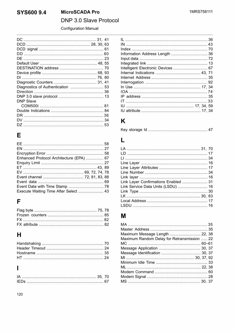
DC .................................................................. 31, 41DCD .......................................................... 28, 30, 63DCD signal ........................................................... 61DD ........................................................................ 60DE ......................................................................... 23Default User .................................................... 48, 55DESTINATION address ........................................ 70Device profile .................................................. 68, 93DI .................................................................... 76, 80Diagnostic Counters ....................................... 31, 41Diagnostics of Authentication .............................. 53Direction ............................................................... 36DNP 3.0 slave protocol ......................................... 13DNP Slave
COM500i .......................................................... 81Double Indications ................................................ 84DR ........................................................................ 36DV ......................................................................... 34DZ ......................................................................... 53
EEE ......................................................................... 58EN ......................................................................... 27Encryption Error .................................................... 58Enhanced Protocol Architecture (EPA) ................ 67Enquiry Limit ......................................................... 27ET ................................................................... 43, 89EV ....................................................... 69, 72, 74, 78Event channel ..................................... 72, 81, 83, 88Event data ............................................................ 69Event Data with Time Stamp ................................ 78Execute Waiting Time After Select ....................... 43
FFlag byte ......................................................... 75, 78Frozen counters ................................................... 85FX ......................................................................... 82FX attribute ........................................................... 82
HHandshaking ........................................................ 70Header Timeout .................................................... 24Hostname ............................................................. 35HT ......................................................................... 24
IIA .................................................................... 35, 70IEDs ...................................................................... 67
IL ........................................................................... 36IN .......................................................................... 43Index ..................................................................... 70Information Address Length ................................. 36Input data .............................................................. 72Integrated link ....................................................... 13Intelligent Electronic Devices ............................... 67Internal Indications ......................................... 43, 71Internet Address ................................................... 35Interrogation ......................................................... 92In Use ............................................................. 17, 34IOA ....................................................................... 74IP address ............................................................ 35IT .......................................................................... 33IU .............................................................. 17, 34, 59IU attribute ...................................................... 17, 34
KKey storage Id ...................................................... 47
LLA ................................................................... 31, 70LD ......................................................................... 17LI ........................................................................... 34Line Layer ............................................................. 16Line Layer Attributes ............................................ 17Line Number ......................................................... 34Link layer .............................................................. 16Link Layer Confirmations Enabled ....................... 31Link Service Data Units (LSDU) ........................... 16Link Type .............................................................. 30LK ................................................................... 30, 63Local Address ....................................................... 17LSDU .................................................................... 16
MMA ........................................................................ 35Master Address .................................................... 35Maximum Message Length ............................ 22, 38Maximum Random Delay for Retransmission ...... 22MC .................................................................. 60–61Message Application ...................................... 30, 37Message Identification .................................... 30, 37MI .............................................................. 30, 37, 92Minimum Idle Time ............................................... 33ML ................................................................... 22, 38Modem Command ................................................ 60Modem Signal ....................................................... 28MS .................................................................. 30, 37
120
1MRS758111MicroSCADA ProSYS600 9.4DNP 3.0 Slave ProtocolConfiguration Manual

Multi-drop network topology ................................. 15
NNCC .................................................................. 7, 81NET .......................................................... 40, 69–70NET database ....................................................... 69Network topologies ......................................... 15–16No limitations ........................................................ 15
OOBJ ....................................................................... 75Object commands ................................................ 89Object Status ........................................................ 42Offset .................................................................... 40OM ........................................................................ 32Open Systems Interconnection ............................ 67Open Systems Interconnection (OSI) ................... 67Operating Mode .................................................... 32OR ........................................................................ 76OS .................................................................. 42, 76Output data ........................................................... 73Outstation Name .................................................. 52OV .................................................................. 89, 91
PParity .................................................................... 20PC ................................................................... 38, 61PD ................................................................... 21, 70Physical layer ....................................................... 67PO ........................................................................ 19Point-to-point network topology ............................ 15Polled Report-by-Exception Operation ................. 69Polling Delay ......................................................... 21Priorities ................................................................ 69Process Data Confirmation .................................. 38Process object types ............................................ 68Protocol ................................................................ 19Protocol converter ................................................ 69PS ......................................................................... 19PU ......................................................................... 61Pulse counters ...................................................... 85Pulse Dialing ......................................................... 61Pulse length .......................................................... 89PY ......................................................................... 20
QQC ........................................................................ 44QL ......................................................................... 89
Queue Clear ......................................................... 44Quiescent Operation ............................................ 69
RRA ................................................................... 89, 91Radio Connection Wait Time ................................ 61Radio Disconnection Delay .................................. 60RB ................................................................... 89, 91RC ........................................................................ 61RD ........................................................................ 20Read-only ............................................................. 15Receive Interrupt Enable Delay ............................ 27Receiver Data Bit Count ....................................... 20Remote Calls Enabled .......................................... 61Remote host ......................................................... 35Remote Terminal Units ......................................... 67Request ................................................................ 88Reset Event Queues ...................................... 77, 80Response ............................................................. 88Response Timeout ............................................... 24Restart bit ............................................................. 76REX ...................................................................... 88REx type ............................................................... 88RI .......................................................................... 27RK ......................................................................... 26RM ........................................................................ 39RS ................................................................... 77, 80RT ......................................................................... 42RTS ................................................................ 23, 26RTS Keepup Delay ............................................... 25RTS Keep up Padding Characters ....................... 26RTS signal ............................................................ 23RTUs .................................................................... 67Running Mode ...................................................... 39RW ........................................................................ 61RY ......................................................................... 25
SSA ......................................................................... 34SB ............................................................. 21, 44, 76SD ............................................................. 19, 70, 72SE ......................................................................... 37Security ................................................................... 8Serial cable ........................................................... 63SF ......................................................................... 45SG ........................................................................ 28Signal Cross-Reference Tool ................................ 81Signal rerouting .................................................... 81Signals .................................................................. 81Single Indications ................................................. 84
121
SYS600 9.4MicroSCADA Pro
DNP 3.0 Slave Protocol
1MRS758111
3.6.2016Issued:C/3.6.2016Version:
Configuration Manual

SOURCE address ................................................ 70SR ......................................................................... 62ST ......................................................................... 42STA objects .......................................................... 33Static data ............................................................. 69Static Report-by-Exception Operation .................. 69Station Address .................................................... 34Station attributes ................................................... 34Station object ........................................................ 33Status codes
Line Layer ......................................................... 92Station Layer .................................................... 92
Status Filtering ...................................................... 45Stop Bits ............................................................... 21SuBset .................................................................. 44Subset levels ........................................................ 67SYS600 .................................................................. 7SYS_BASCON.COM ............................................ 14System
Messages ............................................. 29, 37, 92Objects ....................................................... 14–15
System Device Name ........................................... 19System Messages Enabled .................................. 37SYS Waiting Time ................................................. 42
TTC ......................................................................... 39TCP mode ........................................................... 113TD ......................................................................... 21Test function of link ............................................... 70TI .......................................................................... 24Time Synchronization ........................................... 39Transmission Wait Delay ...................................... 22Transmitter Data Bit Count ................................... 21Transport layer ..................................................... 67Transport Layer Timeout ...................................... 43TT ......................................................................... 43TW ........................................................................ 22
UUA ......................................................................... 46UAL event Identification ................................. 33, 46UAL Event used ................................................... 46UDP Mode .......................................................... 113UI .................................................................... 33, 46UN ............................................................ 38, 89, 92Unsolicited messages .............................. 69, 73, 85Unsolicited Report-by-Exception Operation ......... 69User Roles ............................................................ 51
VVAR ...................................................................... 75Variation ................................................................ 75
WWarm restart ......................................................... 91Wiring ................................................................... 63Write-only ............................................................. 15
XXR ......................................................................... 22
ZZA ......................................................................... 47ZD ......................................................................... 52ZG ......................................................................... 47ZI .......................................................................... 48ZN ........................................................................ 52ZO ........................................................................ 51ZR ......................................................................... 48ZS ........................................................................ 51ZT ......................................................................... 47ZU ................................................................... 48, 55ZV ......................................................................... 50
122
1MRS758111MicroSCADA ProSYS600 9.4DNP 3.0 Slave ProtocolConfiguration Manual


Contact us
1MR
S75
8111
C
/3.6
.201
6 ©
Cop
yrig
ht 2
016
AB
B. A
ll rig
hts
rese
rved
.ABB OyGrid Automation ProductsP.O. Box 614FI-65101 Vaasa
Finland
Tel. +358 10 22 11
Fax. +358 10 224 1094
www.abb.com/substationautomation