Embed Size (px)
Citation preview
UC DAVIS Campus Standards & Design Guide
DIVISION 27 00 00 - COMMUNICATIONS Introduction About this Manual: This document contains the Telecommunications Standards for use by the campus project managers, consultants and telecommunications design professionals who are involved in telecommunications projects on the UC Davis campus. This manual shall be used as a guide for projects providing telecommunications infrastructure and cabling, including inside and outside plant cable, wireless networks, in-building radio systems, broadband video, audio-visual and network systems. Work may include new and renovated buildings, as well as, the upgrading and/or the addition of cabling infrastructures and electronic equipment. This document assumes that the user is familiar with telecommunications distribution systems, the cable and hardware used in them, the cabling pathways and support structures and the installation of cabling, wireless radio, video, audio-visual and network systems in buildings and campus environments. It is not intended to be a training manual in the design of telecommunications distribution systems, a replacement of existing industry standards or used as an installation guide by an installing contractor. Terminology used throughout this document to identify building termination locations is unique only to the UC Davis campus. Terms such as Area Distribution Frame (ADF), Building Distribution Frame (BDF), Intermediate Distribution Frame (IDF) Master Antenna Television (MATV) and Network Access Module (NAM) are used in lieu of industry standard terms, such as Main Cross-Connect (MC), Intermediate Cross-Connect (IC), Horizontal Cross-Connect (HC), Community Antenna Television (CATV) and Information Module (Jack). The requirements for these locations still adhere to the American National Standards Institute (ANSI), Telecommunications Industry Association (TIA) and Electronic Industries Alliance (EIA) standards. Variances or clarification of specific design and/or standards issues shall be submitted to CR on the Non-compliance Form. Forward the Non-compliance Form to the Project Engineer with UC Davis Engineering and Construction Management (ECM), Communications Resources Department. The form may be downloaded from the CR Projects, Telecommunications Standards web site (www.cr.ucdavis.edu). Catalog numbers and specific brands, trade names or manufacturer’s names followed by the designation “or equal” are used in conjunction with material and equipment required by the specifications to establish the standard of quality, utility and appearance required. The contractor shall use the 1st manufacturer listed in the specification, unless the contractor requests a substitution of material. Substitution of material shall be submitted to the University Representative in accordance with Section 01630, Product Substitution Procedures, contained in the Campus Standards and Design Guide.
Communications - 27 00 00 September 2007
1
UC DAVIS Campus Standards & Design Guide
This manual also includes the following appendices:
Appendix A - References contain a list and brief description of the industry standards and guidelines for telecommunications systems and how to obtain a copy of them. Appendix B - Glossary contains the definition of terms used in telecommunications design, engineering, construction and provisioning.
Appendix C - UC Davis Policy and Procedure Manual, Section 310-10.
ASSIGNMENT OF RESPONSIBILITIES Communications Resources (CR) Responsibilities: Communications Resources is responsible for UC Davis’ inside and outside telecommunications system facilities, network connectivity and the associated backbone equipment. Communications Resources’ responsibilities are outlined in the UC Davis Policy and Procedure Manual, Section 310-10 found in Appendix C of this document. These responsibilities include the review of all telecommunications project plans and require the following review items: Communications Resources (CR) shall be provided copies of the Project Planning Guide (PPG), Capital Improvement Budget (CIB), Detailed Project Program (DPP), Design Guide or other such documents describing the University approved program. These documents shall be provided to Communications Resources upon approval of the governing agency responsible for managing that project. Communications Resources shall be provided Schematic Design (SD), Design Development (DD) and Construction Documents (CD) documents for review at each stage of the design process and provided a minimum of ten workdays from date documents are received by CR for review and return of comments. Architects and Engineers (A&E) Role: A&E is the focal point for coordinating the various engineering consultants during the design process. To ensure each design includes all requirements necessary to support current and future telecommunications needs, the information provided in this document shall be included in the project specifications and drawings. When a new building or building renovation is planned, drawings are typically released for review by A&E in the following order:
• Schematic - Initial planning documents and design drawings which assist departments in the early stage of the project.
• Design Development - As the A&E design process progresses, overlays are
developed to show the various structures and systems planned for the building.
Communications - 27 00 00 September 2007
2
UC DAVIS Campus Standards & Design Guide
• Construction Documents - Depict the final design before bid submittal is undertaken.
• Working Copy - Bid Copy. • Submittal - Depict the type and manufacturer of products the contractor plans to
install during the project. • “Record Document” Drawings - Represent the project as it is finally constructed
and are deliverable prior to final inspection of the project. Note: CR’s ECM office review comments shall be incorporated into the project documents prior to the next review phase or an explanation from the design professional shall be provided to the ECM office regarding the status of the referenced comments. Architects, contractors, and telecommunications design professionals shall indicate, on the design drawings and in the design specifications, the location and specification of the physical infrastructure required for a complete telecommunications cabling pathway and distribution system. This physical infrastructure shall include:
• Work Area Outlet (WAO) and Network Access Modules (NAM). Reference Specification 01, NAM Faceplates, Surface Mount Boxes, Wiremold® Adapters and Modules, for a complete description of a NAM.
• Cabling termination hardware for a complete telecommunications (voice and
data), in-building 800 MHz radio, video broadband, audio-visual, and wireless network systems.
• The infrastructure necessary to support the horizontal, riser and campus
backbone cable systems. • The ADF, BDF and IDF locations. • The infrastructure necessary to interconnect buildings, to include conduit,
maintenance and hand holes, building entrances, entrance protectors, cables, splices and connection to Communications Resources service points.
• Grounding and bonding requirements and locations. • Electrical service requirements and service points for ADF’s, BDF’s, and IDF’s,
as well as, any necessary ancillary electrical work as part of the project. • During the planning, design and construction phases of a project, the in-building
800 MHz radio systems shall be planned for and included in the budget. Reference Division 27 60 00, 800 MHz In-Building Radio Systems, in this manual.
A&E shall include CR early in the planning phase. CR can assist in surveying potential building sites for service connections to the existing campus infrastructure and assist in programming the required communication spaces.
Communications - 27 00 00 September 2007
3

UC DAVIS Campus Standards & Design Guide
Communication Consultant/Designer Role A&E, at its option and for a fee, may contract with a communication consultant or request CR to complete a communications design. Regardless of the approach taken, A&E shall provide drawings to the consultant or CR so communication design documents can be created. A&E shall also incorporate comments concerning the project specifications and/or drawings into the various document packages. The Telecommunications Standards Design Process The UC Davis telecommunications standard is divided into Division 27 sections and formatted to follow the Construction Specifications Institute™ (CSI) format:
Division 27 00 00, Communications refers to the Architectural, Electrical & Mechanical Requirements for the Equipment and Telecommunications Rooms that house the ADF, BDF and IDF. The ADF, BDF or IDF are the rooms that house common network equipment, such as switches and UPS’. Division 27 10 00, Structured Cabling refers to the horizontal, riser and outside plant segment of the structured cabling system, to include WAO’s, the hardware for terminating the horizontal cable from the WAO, along with riser cabling to the IDF and testing requirements. Division 27 20 00, Data Communications refers to the campus wireless Local Area Network (LAN) systems. Division 27 30 00, Voice Communications refers to indoor and outdoor telephone mounts and phone sets. Division 27 40 00, Audio-Video Communications refers to the campus Master Antenna Television (MATV) System and the campus building Sound, Video and Remote Control systems. Division 27 60 00, 800MHz In-Building Radio Systems, refers to the campus trunked radio system.
The design, engineering and installation of voice and data network electronic equipment are typically accomplished by Communications Resources.
Communications - 27 00 00 September 2007
4
UC DAVIS Campus Standards & Design Guide
COMMUNICATIONS 27 00 00 DEFINITIONS During a building design phase, there are a number of communication infrastructure requirements that must be addressed by the architect. The following information is provided to address those architectural requirements and how they shall be incorporated in the final design.
Telecommunications Spaces (TS) Telecommunications Spaces are special-purpose spaces that provide a secure operating environment for telecommunications and/or network equipment. Each type of space has a specific function and requires its own individual space within a facility. Depending on the building size, design and network requirements, one or more of these functions may be combined into one space. The industry term “Telecommunications Spaces”, when used, shall refer to Equipment and Telecommunications Rooms, as well as, ADF, BDF and IDF in this Telecommunications Standards document. Equipment Room (ER) The Equipment Room (ER) is the room within a building that houses the Area Distribution Frame (ADF) and Building Distribution Frame (BDF) for telecommunications equipment that meets the voice, data, video, radio and wireless needs of an entire building, and/or a designated area on the UC Davis campus. In some cases, an ER may also contain the Entrance Facility (EF) and Intermediate Distribution Frame (IDF). An ER provides a controlled environment to house telecommunications equipment, termination hardware, splice closures, Main Telecommunications Grounding Busbar (MTGB) grounding and bonding facilities and protection apparatus where applicable. Digital Loop Carrier equipment, local area network switches, video distribution equipment, wireless network equipment, 800MHz in-building radio equipment and large uninterruptible power sources are types of telecommunications equipment found in an ER. ER’s are considered distinct from Telecommunications Rooms (TR) due to the nature and/or complexity of the equipment they contain. ER’s shall be designed and provisioned according to the requirements in ANSI/TIA/EIA-569-B. The term ER, when used, refers to TR’s, ADF, BDF and/or IDF’s on the UC Davis campus. Telecommunications Room (TR) Telecommunications rooms (TRs) differ from equipment rooms (ERs) and entrance facilities (EFs) in that they are generally considered to be floor serving as opposed to
Communications - 27 00 00 September 2007
5

UC DAVIS Campus Standards & Design Guide
building or campus serving. Every building is served by at least one TR or ER, with a minimum of one TR per floor. The TR is the room within a building that houses the Intermediate Distribution Frame (IDF) on the UC Davis campus for the primary function of providing a connection point between backbone and horizontal infrastructures. ANSI/TIA/EIA-568-B.1 has replaced the term Telecommunications Closet with the term Telecommunications Room. BDF may also be called a TR. The BDF is a building serving space providing a connection point between campus backbone cables and the building infrastructure system. The BDF may be floor serving when collocated with an IDF. Horizontal and backbone cable terminations shall be accomplished using manufactured patch panels and patch cords for data and jumper wire for voice circuits. On the UC Davis campus, the term IDF shall be used for termination points servicing WAO locations. TR’s shall be designed and provisioned according to the requirements in ANSI/TIA/EIA-569-B. The term TR’s, when used, refers to TS’s, BDF’s and/or IDF’s on the UC Davis campus. TELECOMMUNICATIONS SPACES MINIMUM REQUIREMENTS Room Location There are a number of factors that need to be considered when placing Telecommunications Spaces (TS) within new or remodeled facilities. Site selection factors for the various rooms are addressed below. Of these factors, the two most important are “stacking” of the spaces and providing a method that would allow the spaces to be expanded, if required, in the future. Telecommunications Spaces shall be: Dedicated to the buildings telecommunications function and related support facilities. Shall not be shared with electrical equipment, building services or other equipment other than those required in direct support of the telecommunications equipment and services. Reference UCD Policy & Procedure Manual, Section 310-10, Telecommunications Services dated 1/15/02. Located as close as practical to the center of the area served and preferably in the core area. The average horizontal cable run is 150 feet or less and no individual cable run shall exceed 295 feet; minimizing the length of the backbone and horizontal distribution cables. Building entrance cables shall not be exposed for a cable length distance of more than 50' per the 2002 California Electrical Code, Articles 770-50 and 800-50.2. Horizontal pathways shall terminate in the TS located on the same floor as the area being served.
Communications - 27 00 00 September 2007
6

UC DAVIS Campus Standards & Design Guide
Avoid locations that limit expansion such as structural steel, stairwells and elevator shafts, outside walls or other fixed building walls. Be accessible directly from public hallways and not through offices or other utility spaces. Be easily accessible for the delivery of large equipment to the room. Have easy access to distribution cable pathways. Vertically aligned (Stacked) within a multistory building; each IDF is placed above the BDF/IDF (TS) on the floor below. Located as close as practical to the vertical backbone pathway and in a dry area that is not subjected to flooding. Specifications for related facilities shall accommodate the applicable Seismic Zone 4 requirements. Telecommunications Spaces shall not:
Contain other building systems, such as, but not limited to, audio-visual (A/V) equipment, access control systems, fire alarm panels, building management systems or computer servers. No other building systems shall be housed within this room without the prior written approval of Communications Resources. Reference UCD Policy and Procedures Manual Section 310-10, Telecommunications Services, dated 1/15/02. Be located near electrical power supply transformers, elevator or pump motors, generators, x-ray equipment, radio transmitters, induction heating devices and other potential sources of electromagnetic interference (EMI) and radio frequency interference (RFI). Be located near sources of mechanical vibration that could be conveyed to the room via the building structure. Equipment not related to the support of the telecommunications function (e.g. sprinkler, steam, chilled water, supply and waste piping, ductwork, pneumatic tubing, etc) shall not be installed in, pass through, pass overhead or enter the telecommunications space. Be located below water level unless preventive measures against water infiltration are employed. A floor drain and/or sump pump shall be provided within the room if risk of water ingress exists. Contain water or drain pipes (to include overhead piping of any type) not directly required in support of the equipment within the room. Drain (drip) pans with an appropriate drain shall be placed beneath each pipe, if required. Pipes for sprinkler heads located within the room shall not be located directly above electronic equipment racks and/or cabinets.
Communications - 27 00 00 September 2007
7

UC DAVIS Campus Standards & Design Guide
Be located in any place that may be subject to water or steam infiltration, humidity from nearby water or steam, heat and any other corrosive atmospheric or environmental conditions. Share space in electrical closets, boiler rooms, washrooms, janitorial closets and storage rooms. In addition, acoustic noise levels in the Telecommunications Spaces must be maintained at a minimum level by locating noise-generating equipment outside the TS. Room Sizing The size of the TS is dependent upon the size of the area that the room will serve and the variety of equipment installed within the room. The TS shall provide enough space for all planned termination and electronic equipment and cables that will be installed to within the telecommunications room; including any environmental control equipment, power distribution/conditioners and uninterrupted power supply systems. The TS shall be design with provisioning of space to access equipment for maintenance and administration and equipment changes with minimal disruptions. There shall be a minimum of one TS per floor. One additional TS for each area up to 10,000 sq. ft. shall be provided when the floor area to be served exceeds 10,000 sq. ft or the horizontal distribution distance to the workstation exceeds 295’. Based on one workstation per 100 square feet (sq. ft.), the TS shall be sized as follows:
• If the serving area is 5,000 sq. ft. or less, the TS shall be 10-feet wide by 8-feet
long. • If the serving area is between 5,000 and 8,000 sq. ft., the TS shall be 10-feet
wide by 9-feet long. • If the serving area is between 8,000 and 10,000 sq. ft., the TS shall be 10-feet
wide by 11-feet long. • If the floor area is over 10,000 sq. ft., then the TS size shall be increased, based
upon 0.75 sq. ft. for every additional 100 sq. ft. of usable space the TS will support.
The sizes of all telecommunications spaces (ADF/BDF/IDF) listed are minimum requirements. Depending on the requirements and services performed by the building occupants, additional space may be required. Larger size buildings may require additional rows of equipment racks or cabinets. Contact CR for instruction on how large the ER/TR’s need to be. HVAC All Equipment Rooms must be environmentally controlled 24 hours a day seven days a week. If the building system cannot assure continuous operation, a stand alone unit shall be provided for the telecommunications space. If a standby power source is available in
Communications - 27 00 00 September 2007
8
UC DAVIS Campus Standards & Design Guide
the building, consideration should be given to connecting the HVAC system serving the telecommunications equipment room to the standby supply.
• HVAC shall be included in the design of the room to maintain a temperature between 68 and 72 degrees Fahrenheit.
• A positive pressure differential with respect to surrounding areas should be provided.
• The humidity must be maintained between 30 and 55 percent. • The filters in the HVAC system should have an ASHRAE dust spot rating of 85%
or better. Room Lighting It is important that proper work lighting be provide in all Telecommunications Spaces. Provide a minimum equivalent of 50 foot-candles when measured three feet above the finished floor and in the middle of all aisles between racks or cabinets. Be mounted a minimum of 8-feet, 6-inches above the finished floor. Position the room light fixtures above aisle area and between equipment racks and cabinets only. Do not place lighting fixtures directly over equipment racks, cabinets, cable trays or runways as to cast a shadow over the work area. Have light switches located near each entrance door of the TS. Dimmer switches are not permitted. Recommend at least one light fixture be on an emergency power circuit, if available in the building. Lighting shall not receive power from the same electrical distribution panel breaker as the telecommunications equipment in the TS.
Water Infiltration As stated earlier, Telecommunications Spaces shall not be located below water level unless preventive measures against water infiltration are employed. The TS shall be free of water or drain pipes not directly required in support of the equipment within the TS. A floor drain, automatic pump, and warning alarm shall be provided within the TS if the risk of water ingress exists.
Fire Safety and Protection Portable fire extinguishers shall be provided and maintained within 75-feet or less travel distance from any part of the occupied space within the TS per campus requirements. The size of the fire extinguisher shall be a minimum 2-A, 10-B, C rating.
Communications - 27 00 00 September 2007
9

UC DAVIS Campus Standards & Design Guide
If overhead sprinklers are required within the equipment area, the sprinkler heads shall be provided with protective wire cages to prevent accidental operation. Drainage troughs shall be placed under the sprinkler pipes to prevent leakage onto the electronic equipment within the room. Drain troughs shall be provided with a drain that will route the water outside of the TS. Alternate fire-suppression systems should be considered in these areas. Additional equipment such as fire alarm panels, building monitoring devices, building access systems, A/V systems and file servers shall not be located in the TS. Space for these services shall be provided as part of the electrical room or in a separate location. If an access raised-floor system is to be installed in any TS and a fire detection system is required under the floor, the system shall be a cross-zone detection system. In addition, placement of the detector may affect the way cables are routed under a raised floor. If ionization detectors are installed, there is a potential problem with the accumulation of dust under the floor. It is possible during the performance of cable work under the floor that dust could set off the detectors. Provisions shall be made in the fire detection system design to reduce the possibly of false alarms and activation of a fire suppression system, such as, but not limited to, temporarily disarming the system. Emergency lighting and signs shall be properly placed such that an absence of light will not hamper emergency exit.
Doors The door shall be a minimum of 3-feet wide and 6-feet, 7-inches high, without a doorsill. Door shall be fire rated to match the fire rating of the wall in which it is installed, if applicable, or as required by local code requirements. Doors shall not contain a glass viewing window or panel for added security. If it is anticipated that large equipment will be delivered to the TS, a double door 6-feet wide by 7-feet, 5-inches high without a doorsill and center post is recommended. The door shall have a gasket to prevent dust from entering the room. TS doors that open to an outside environment shall be rated for exterior use and shall have a weatherproof gasket to prevent vermin, water, dirt and dust from entering the room. A positive pressure type of HVAC system shall be installed in this type of TS. Doors shall open outward (code permitting). The keying of doors for all TS and Controlled Environmental Facilities (CEF) shall be keyed alike. Contact CR for proper key number. Signage, when required, shall be consistent with UC Davis and/or building requirements. Signs shall indicate “Communications Room”.
Communications - 27 00 00 September 2007
10

UC DAVIS Campus Standards & Design Guide
Interior Finishes Floor: Floors shall be sealed concrete or tile to minimize dust and static electricity. Removable computer floor tiles shall be of a tile type surface. Floor loading capacity in the ER (ADF/BDF) shall be designed for a minimum distributed load rating of 100 lbf/ft² and a minimum concentrated load rating of at least 2000 lbf. The floor loading for a TR (IDF) shall be designed for a minimum load rating of 50 lbf/ft². It shall be verified that concentrations of proposed equipment do not exceed the floor limit. If a raised floor system is used, then it is possible the space will have to comply with the requirements of Article 645 Information Technology Equipment of the 2001 California Electrical Code and NFPA 75 Standard for the Protection Information Technology Equipment, 2003 Edition. Finishes shall be light in color to enhance room lighting. Walls: Interior finishes shall be in a light color to enhance room lighting. All four walls shall be lined with plywood backboards. All plywood backboards shall meet the following minimum requirements.
• All plywood shall be void free 3/4 inch x 4 foot x 8 foot, mounted vertically. • Fire Rated by the manufacturer and painted with two coats of white paint. At
least one (1) Manufacture’s Fire-Rated stamp shall be visible per sheet or partial sheet of plywood when painting is completed.
• Plywood shall be mounted vertically starting at 6-inches above the finished floor to a height of 8-feet, 6-inches.
The plywood shall be securely fastened to the wall-framing members. Wall anchors shall be flush to the plywood surface as to not obstruct the mounting of cabling hardware. The walls shall be capable of supporting attached equipment. Ceilings: No suspended ceilings. The walls must be continuous from floor to underside of the floor above. Open structure ceilings shall provide the same environmental conditions as a closed type of ceiling structure. Hard ceilings shall have EMT type conduit or sleeves installed to facilitate the installation and fire stopping of cables. Clearances: The minimum clearance height in the room shall be 9-feet without obstructions.
Communications - 27 00 00 September 2007
11

UC DAVIS Campus Standards & Design Guide
Provide the following clearances for equipment and cross-connect fields in the Telecommunications Spaces:
• Allow a minimum of 36-inches of clear working space in front and rear of equipment cabinets, racks and cross-connect fields.
• Allow for 6-inch depth off wall for wall and rack mounted equipment. • Provide a minimum 36-inch aisle between each row of racks. • A minimum aisle clearance of 30-inches is required at one end of each row of
racks for an exit access. Note: In many cases, equipment and termination hardware may extend beyond racks and backboards. It is important to note that the clearance is measured from the outermost surface of these devices, rather than from the mounting surface of the rack or backboard. Telecommunications Spaces Construction Sequence Prior to the installation of cables, telecommunications and/or network equipment, all TS’s shall be completed. In all cases, this means the TS shall have construction priority and may have to be constructed out of the normal building sequence. At a minimum, the following items shall be completed:
• All wall and rack-mounted electrical receptacles installed and operational. • Interior finishes completed. • Lighting and air conditioning systems installed and operational. • Lockable doors installed and keyed to the CR standard.
Special Design Considerations Slab on Grade If a slab on grade approach is planned for the first floor of newly constructed buildings, then special attention shall be provided to potential communication WAO’s that may be installed in the floor. The following minimum requirements:
• Supporting conduits shall run beneath the slab and shall be PVC schedule 40 or better.
• At no time shall the conduit run below the membrane barrier or be placed directly in the soil.
• Conduits shall not contain more than two 90-degree bends and exceed more than 100-feet in length between pulling points.
Communications - 27 00 00 September 2007
12

UC DAVIS Campus Standards & Design Guide
ELECTRICAL
Design Requirements Following are the basic guidelines for the electrical design consultant. These design guidelines are considered to be minimum requirements. The electrical design consultant shall contact A&E to determine if there are any additional or special requirements. CR requires this information be included in drawings and specifications. If the current Construction Specifications Institute (CSI) Master Format™ is used, a separate section within the current Electrical Division shall be used to address: 1. Conduits for telecommunications use. 2. Work Area Outlet (WAO) and pull boxes for telecommunications use. 3. Telecommunications cable support system (cable tray and J-hook). 4. The telecommunications grounding system. 5. Testing requirements. These sections and drawings shall be made available to CR. Telecommunications Space (TS) Electrical Requirements A 60-amp sub-panel or dedicated circuits shall be installed in all ADF/BDF/IDF (ER/TR) rooms. The estimated electrical load for the telecommunications space shall not exceed 80% of the panel. At a minimum, ALL TS’s shall be provided dedicated electrical service. Dedicated power circuits from shared panel boards shall be provided with both transient voltage surge suppression and electrical high frequency noise filtering. Finish color shall be Blue. If a low number of telecommunications spaces are planned, one electrical panel may serve multiple telecommunications spaces as a design alternative. Sub-panels shall be located near the room entrance door, whenever possible, to conserve wall space and should be connected to an emergency power source whenever such a source is provided to the building. Convenience duplex receptacles shall be:
• Mounted in each room at +18-inches AFF and horizontally spaced not to exceed 6-feet around the perimeter of the room.
• Non-switched, 120VAC 20 Amp, duplex and divided equally on branch circuits, (i.e. all receptacles in the same room shall not all be on the same circuit). No more than four (4) receptacles shall be on the same circuit.
• Each receptacle shall be clearly marked with its respective circuit number. If the room has a raised floor, all under floor receptacles shall be side mounted on a flex whip not to exceed 30-inches in length. All circuits for under floor receptacles shall be of a ground-fault interrupter type.
Communications - 27 00 00 September 2007
13

UC DAVIS Campus Standards & Design Guide
HVAC systems shall not use the same electrical panel that is used to support telecommunications spaces. Equipment Rack and Cabinet Electrical Requirements Equipment racks identified for electronic equipment shall have the following installed:
• One (1) quad device box containing two (2) duplex 20 Amp, 120V AC NEMA 5-20R-spade receptacles located on separate dedicated circuits in the room sub-power panel.
• Device box shall be mounted on the backside of each rack 15-inches Above the Finished Floor (AFF). The placement of this device box and its EMT conduit shall not block or interfere with the equipment mounting area (rails) on either side of the rack.
• Flexible conduit shall be used to attach electrical service to the equipment rack. Flexible conduit is required to prevent the shearing of the conduit during a seismic event.
• Reference Division 27 11 16, Communications Cabinets, Racks and Enclosures, Figure 31.
Enclosed cabinets identified for electronic equipment shall have the following installed:
• Two (2) quad device boxes containing two (2) duplex 20 Amp, 120V AC NEMA 5-20R-spade receptacles to separate dedicated circuits located in the room sub-power panel.
• One (1) device box shall be mounted toward the back of the cabinet near the top inside area of the cabinet to provide electrical power to the cooling fan(s). The second device box shall be located 15-inches above the floor toward the back of the cabinet.
• The device boxes and EMT conduit shall not block or interfere with the equipment mounting area (inside and outside mounting rails) within the cabinet.
• Reference Division 27 11 16, Communications Cabinets, Racks and Enclosures, Figure 30.
Special considerations:
• ADF equipment racks and cabinets shall have 30 Amp, 120V AC NEMA 5-30R-spade receptacles in place of the 20 Amp, 120V AC NEMA 5-20R-spade receptacles.
• Provide a duplex 20 Amp, 220V receptacle for a DLC cabinet. Contractor may be required to hard wire the 20 AMP circuit into the cabinet equipment.
Electromagnetic Interference The TS shall not be located near electrical power supply transformers, elevators, pump motors, generators, x-ray equipment, radio transmitters, radar transmitters, induction heating devices or other potential sources of electromagnetic interference (EMI).
Communications - 27 00 00 September 2007
14

UC DAVIS Campus Standards & Design Guide
Emergency Back-up Power
• Sub-panels shall be connected to an emergency power source whenever such a source is provided to the building.
• Emergency power is especially important in the TS’s that house Digital Loop Carrier systems to ensure voice and emergency systems remain operational during power outages that may extend past the systems battery backup capability.
MECHANICAL (HVAC) Design Process Following are the basic guidelines for the mechanical design consultant. These design guidelines are considered to be minimum requirements. The Heating, Ventilation and Air Conditioning (HVAC) consultant shall contact CR to determine if there are any other special requirements. HVAC Requirements The air handling system and environment controls for TS’s shall be continuous and dedicated and designed to provide positive airflow and cooling even during times when the main building systems are shut down. This may require separate air handlers and/or small stand-alone cooling systems that are thermostatically controlled in this space. Whether this space is separate or combined with the building service entrance, it is by almost every definition, a specialized area. The room will house sensitive electronic components that will generate heat 24 hours a day, 365 days a year and must be cooled to maintain operating performance. If the building's HVAC system cannot meet this requirement, then a stand-alone HVAC system with independent controls for heating, ventilation, and air conditioning sensors and control equipment related to the environment within the TS shall be located in the TS. The HVAC unit will not be powered off the same electrical panel as the telecommunications spaces. Final BTU load estimates can be provided after the equipment has been selected. For maximum planning purposes, assume at least 5,000 BTUs per equipment rack/cabinet to be installed. A typical telecommunications space contains at least three racks, with one rack dedicated to electronics. In larger or critical installations, such as Area Distribution Frames (ADF), the air conditioning system (or that part of a larger system) may have to be connected into a backup generator system. Provisions shall be made so the telecommunications equipment will not "thermal out" or overheat due to a loss of power to the air conditioning system. Check with CR to see if this condition exists.
Communications - 27 00 00 September 2007
15

UC DAVIS Campus Standards & Design Guide
A positive pressure differential with respect to the surrounding areas shall be provided. The ambient temperature and humidity shall be measured at the distance of 5-feet above the floor level. After the equipment is in operation, the measurement can be taken at any point along an equipment aisle centerline. The normal temperature range is 68-degrees F to 72-degrees F with a humidity range of 35% to 55% relative. The TS shall be protected from contaminants and pollutants that could affect operation and material integrity of the installed equipment. When contaminants are present in concentrations greater than indicated in ANSI/TIA/EIA-569-B, Table 8.2-2, vapor barriers, positive room pressure or absolute filters shall be provided. The UC Davis A&E office shall ensure the TS environmental systems are tested and certified, any/all construction filters have been removed and replaced with appropriate system filters, and that they meet the TS environmental requirements. Fire Smoke Dampers If the room is fire-rated, fire/smoke dampers shall be required for supply and exhaust air. BUILDING DESIGN REQUIREMENTS Work Area Outlets (WAO) WAO density: 1. A minimum of one WAO location containing one Voice and Data NAM shall be
installed per work area. For planning purposes, space allocated per work area averages 100-square feet.
2. For building areas where it is difficult to add additional WAO’s at a later date (i.e. private office space), a minimum of two separate WAO locations shall be provided in the initial design for that area, and they shall be located to offer maximum flexibility for change within the work area, (i.e. on opposing walls in private office space).
3. A minimum of one WAO shall be installed with a minimum of two Voice NAM’s at the Fire Alarm Control Panel (FACP) located in the electrical or mechanical room.
4. A minimum of one WAO shall be installed with a minimum of one Voice NAM for each elevator phone at the Elevator Control Panel.
5. A minimum of one WAO shall be installed with a minimum of one Voice or Data NAM at the Building Environmental Control Panel.
6. A minimum of one WAO shall be planned for any Building Access Systems (card and palm readers) that may be installed in the building.
Communications - 27 00 00 September 2007
16

UC DAVIS Campus Standards & Design Guide
7. A minimum of one WAO shall be planned with a minimum of one Voice NAM for each wheel chair elevator phone.
8. WAO locations shall be coordinated with the furniture layout. A power receptacle should be installed near each WAO location (i.e. within 3-feet). WAO locations are typically at the same height as the power receptacles.
9. Open office area interior design, telecommunications distribution planning, and power system distribution planning should be coordinated to avoid conflicting assignments for pathways or WAO locations, installation sequencing problems, and other difficulties.
Courtesy, Pay, Text, Emergency and Wheel Chair Elevator Telephones In order to comply with the American Disabilities Act (ADA) Accessibility Guidelines: 1. The mounting height of the device box for Wall Mounted Telephones shall be 40-
inches Above the Finished Floor (AFF). Wall-mounted telephones shall not be installed above a counter top.
2. The mounting height of the device box for a wheelchair accessible telephone (to include payphones and wheel chair elevator phones) shall be 40-inches AFF.
3. If a Text Telephone is required, it shall not be mounted to the wheelchair accessible telephone position. The text telephone unit shall require a power receptacle at 18” AFF under the Text Telephone.
4. If a wheelchair elevator is planned, a WAO shall be installed as close as possible to its location for the installation of an emergency phone.
Building interfaces Furniture pathways are entered from building walls, columns, ceilings, or floors. The interface between the building and furniture requires careful planning and may require special products or furniture options. Safety, reliability, and aesthetic concerns all favor concealment of the building and furniture pathway interface. These pathway interfaces shall not trap access covers or otherwise block access to WAO’s, building junction boxes or pathways. Pathways used to interconnect the furniture with building horizontal pathways shall be provided with a cross-sectional area at least equal to the horizontal pathways cross-sectional area for the floor area being served. Walls and columns Raceways shall be provided between furniture pathways and the inside of building walls or columns.
Communications - 27 00 00 September 2007
17

UC DAVIS Campus Standards & Design Guide
Floors A raceway shall be provided between furniture pathways and horizontal floor pathway terminations (end of conduit, flush junction boxes, recessed junctions boxes, etc.). Alignment of furniture with building modules, duct locations and other cable delivery means should be considered as part of the layout planning. Furniture shall not be arranged such that pathway interfaces are in aisle spaces, where people walk or place their feet, or other places where such obstructions could create a hazard. Telecommunications consultant shall coordinate the furniture layout with the department. Roof A&E shall contact CR to determine if there are any special requirements that could affect the roof design or structure. There is the possibility that an 800MHz’s in-building radio antenna system may have to be installed on the roof. If an antenna system is to be installed: 1. Additional space may be required to house the radio system equipment in the TS. 2. Conduits from the TS to the roof shall be required. 3. Additional AC power may also be required. Campus Environments Construction involving a new or existing building structure shall have an assessment of the outside conduit infrastructure, (i.e. connections between buildings) accomplished very early in the project cycle. This assessment is of particular importance if demolition of any structure is required as part of the overall project, and/or the new project may impact an existing conduit infrastructure. Tenant Improvement Project As part of the construction process for leased space, plans shall be made to remove any existing cable that may otherwise become abandoned. Abandoned cables, not identified and labeled for future use, increase the fire fuel load and shall be removed in accordance with the 2002 National Electrical Code. CR shall be contacted and requested to survey the existing cable plant. There is a possibility that all or a portion of the existing installed cable may be reusable. Construction Documents The A&E Project Manager shall ensure that CR has the opportunity to review and comment on all drawings and/or specifications that have any impact on the Telecommunications Infrastructure.
Communications - 27 00 00 September 2007
18

UC DAVIS Campus Standards & Design Guide
Project Drawings Project drawings shall include the following site construction information: • Details of typical trench cross sections showing conduit locations in the trench,
clearances from final grade, backfill materials and depths, pavement cutting information, and compacting requirements for both paved and unpaved areas.
• Construction notes applicable to the work being performed.
• A scale drawing showing location ties to existing structures, cable, conduit, MH/HH’s, and any conflicting substructures. Profile drawings of congested areas where vertical and horizontal separation from other utilities is critical during cutting and placing operations.
• A legend explaining industry standard drawing symbols of all relevant structures and work operations.
• Conduit types, dimensions, and wall-to-wall measurements when used with MH/ HH, pedestals and Equipment and Telecommunications Rooms (ER/TR’s).
Common Work Results for Communications 27 05 00 Site construction includes support structures such as aboveground and underground conduit systems, maintenance holes (MH), hand holes (HH) and pole lines. Work performed in this segment shall be designed and installed per the California Electrical Code (CEC). Also reference the National Electrical Safety Code (NESC), California PUC General Orders 95 and 128 and the TIA-758-A Specifications for Outside Plant Construction.
Design Activities:
• Identifying conduit and cable routes from building to building. • Selecting cable distribution methods. • Determining maintenance hole and hand hole requirements. • Determining any obstacles, existing conduit and cable facilities or other
underground utilities in the proposed construction area. • Noting if right-of-way permits or ease8ments are required. • Determining if conditions exist that requires environmental impact applications. • Determining electrical protection and bonding/grounding requirements.
Communications - 27 00 00 September 2007
19

UC DAVIS Campus Standards & Design Guide
Cable Distribution Methods Communications Resources Engineering and Construction Management (ECM) office shall be contacted to determine the best cable distribution method along the proposed cable route. The distribution may be one or a combination of underground, direct-buried, directional boring or aerial methods. An underground cable system consists of cables placed in buried conduits connected to maintenance holes (MH) and hand holes (HH). Conduits are also installed from the building entrance location to poles, pedestals, MH’s and HH’s. When required, splices shall be located in maintenance holes only. A direct-buried cable system consists of cables and associated splices directly placed in the earth. The trench runs from the building entrance location to a pole, pedestal, MH or HH. This method is used only in cases where underground or aerial installations cannot be accomplished. Prior approval from the ECM office shall be obtained prior to the design of a direct-buried system. An aerial cable system consists of cables installed on aerial supporting structures such as poles, sides of buildings and other above ground structures. Note: An underground cable system shall be used if an existing or new conduit route is available between buildings.
Grounding and Bonding for Communications Systems 27 05 26 Introduction These specifications provide a minimum configuration that shall be used when planning new construction or major remodeling of an existing facility. Communications Resources shall be consulted early during the utilities planning phase of the project since each site may have technical requirements requiring a modification of these specifications. The following information is intended to act as a guide to assist the designer in planning, designing and installation of a technically sound grounding and bonding solution for Telecommunication Spaces. The following information and terminology was obtained from ANSI J/STD-607-A, Commercial Building Grounding and Bonding Requirements for Telecommunications, National Electrical Code (NEC) and BICSI guidelines. Compliance with the National Electrical Code (NEC) and local codes mandated by the authority having jurisdiction (AHJ) is essential for the proper application of this Manual. If the designer finds a conflict between a local safety code, BICSI guidelines, and the manufacturer’s requirements, the conflict should be resolved with the authority having jurisdiction (AHJ) before proceeding.
Communications - 27 00 00 September 2007
20

UC DAVIS Campus Standards & Design Guide
References ANSI-J-STD-607-A Commercial Building Grounding (Earthing) and Bonding Requirements for Telecommunications ANSI/TIA/EIA-606-A Administration Standards for the Telecommunications Infrastructure of Commercial Buildings. California Electrical Code Aericle250 and references therein. California Electrical Code Article 800. In the event of conflicting requirements, California Electrical Code requirements shall prevail. Telecommunications Bonding Infrastructure General There are three separate and distinct grounding systems that should be in place at every site: • ac grounding electrode system (e.g., also known as the earthing system). • Equipment grounding system (e.g., also known as the equipment bonding system). • Telecommunications bonding infrastructure. Ac grounding electrode ground systems shall conform to the CEC and NESC specifications. Approved ac grounding electrodes are: • Building entrance power ground from transformer – single point • Building steel (the metal frame of the building itself) • Building footing (a concrete-encased electrode near the bottom of the building’s foundation). • Ground ring (20-feet or more of bare copper wire in direct contact with the earth). This ring normally encircles the building. • Metallic power service conduit, enclosure, or grounding electrode • Ground rod or pipe Equipment grounding includes: • Bare copper conductors. • Insulated conductors. • Metallic conduits and the nationally recognized testing laboratory (NRTL) listed fittings. • AC electrical panel boards and the NRTL-listed fittings. • Junction boxes. • Outlet boxes. • Metallic raceways. In addition to the normal electrical ground system, a Main Telecommunications Ground Busbar (MTGB) and a Telecommunications Ground Busbar (TGB) system is required
Communications - 27 00 00 September 2007
21

UC DAVIS Campus Standards & Design Guide
per ANSI/EIA/TIA-STD-J-607-A. These grounding systems shall be installed to support the telecommunications infrastructure. A TMGB shall be located in the ER (ADF/BDF). The TMGB is to be bonded to the nearest approved building grounding electrode (e.g., structural steel or ground rod) and.equipment grounding system (ac branch circuit panel board’s equipment grounding busbar) by conventional welds, exothermic welds clamp-and-braze method, or UL approved compression type connectors where practical. Exothermic welds are the preferred method. This will minimize (and possibly eliminate) voltage drops between the telecommunications grounding infrastructure and the ac grounding systems during lightning, EMI/RFI, and ac electrical fault conditions. In each TR (IDF), a TGB shall be installed. The TGB shall be bonded to the electrical panel serving the area where the TGB is installed, bonded to building steel and bonded in series to the main TMGB. In a renovation or remodeling project where a suitable ground to the electrical service ground is not available, a grounding electrode shall be installed in accordance with the CEC Section 250-70. Communications bonding relies on short direct paths that have minimum resistive and inductive impedance: Bonding conductors shall be installed with the shortest length possible to decrease impedance issues. Bonding conductors shall be routed with minimum bends or changes in direction. Bonding conductors shall be labeled. The Bonding Conductor for Telecommunications, each telecommunications bonding backbone (TBB) conductor shall be green or marked with a distinctive green color. A grounding equalizer (GE) is not required. Bonding and sizing the telecommunications bonding backbone (TBB) The TBB shall be a copper conductor. The minimum TBB conductor size shall be a No. 6 AWG. The TBB should be sized at 2 kcmil per linear foot of conductor length up to a maximum size of 3/0 AWG. The TBB may be insulated. If the TBB is insulated, the insulation shall meet the fire ratings of its pathway. The sizing of the TBB is not intended to account for the reduction or control of electromagnetic interference. The TBB should be calculated for a size that conforms to the guidelines set by the NEC. Reference Table 1 Sizing of TBB.
Communications - 27 00 00 September 2007
22

UC DAVIS Campus Standards & Design Guide
Table 1 Sizing of TBB.
Sizing of the TBB TBB length linear m (ft) TBB Size (AWG)
less than 4 (13) 6 4 – 6 (14 – 20) 4 6 – 8 (21 – 26) 3 8 – 10 (27 – 33) 2 10 – 13 (34 – 41) 1 13 – 16 (42 – 52) Jan-00 16 – 20 (53 – 66) Feb-00
greater than 20 (66) Mar-00
Bonding connections shall be made directly to the points being bonded, avoiding unnecessary connections or splices. All grounding and bonding connectors shall be listed by a nationally recognized testing laboratory (NRTL) as required by the NEC. The grounding or bonding conductor shall be connected to the grounding electrode by exothermic weld, listed lugs, listed pressure connectors, listed clamps, or other listed alternatives. Bonding Connections Typical connections are made using: • Bolts or crimps (e.g., connectors, clamps, or lugs)—Where possible, irreversible compression-type connections and two-hole lugs should be used. Laboratory-tested hardware should always be used. • Exothermic welding—A seamless molecular bond of metals is commonly applied to: – Connections to, and within, the ac grounding electrode system. – Locations requiring minimal maintenance. – Parts of grounding systems that are subject to corrosion or that must reliably carry high currents. – All connections that are buried. – Cable-to-lug connections. – Bonds to structural steel. All bonding connections should follow the manufacturer’s guidelines.
Communications - 27 00 00 September 2007
23

UC DAVIS Campus Standards & Design Guide
Figure 1 Small Systems (Single ER/TR within a building)
NOTE: Small system installations must meet ANSI J/STD-607-A. Large Systems (Multiple ER/TR within a Building) Multiple busbars are used where multiple ERs, TRs, and EFs exist in large buildings. Guidelines for this method are detailed in ANSI J/STD-607-A; Each TMGB or TGB must have an effective bonding connection to the nearest approved building grounding electrode (e.g., structural steel) and the equipment grounding system (e.g., ac branch circuit panel board’s equipment grounding busbar). See Figure 2 Recommended Large System Arrangement.
Communications - 27 00 00 September 2007
24
UC DAVIS Campus Standards & Design Guide
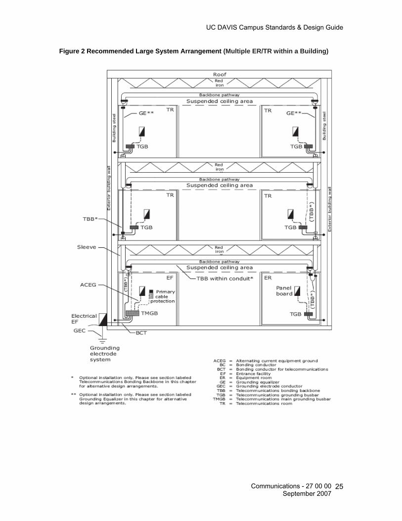
Figure 2 Recommended Large System Arrangement (Multiple ER/TR within a Building)
Communications - 27 00 00 September 2007
25

UC DAVIS Campus Standards & Design Guide
Entrance Facility (EF) Telecommunications Main Grounding Busbar (TMGB) The TMGB serves as the dedicated extension of the building ac grounding electrode system for the telecommunications infrastructure. It serves as the central attachment point for the TBB and equipment. The TMGB must be a predrilled copper busbar with holes for use with standard-sized lugs, have minimum dimensions of 6.3 mm (0.25 in) thick by 101 mm (4 in) wide, and be minimum 20” (see Figure 3). Furthermore, it must be listed by an NRTL. Figure 3 Typical Telecommunications Main Grounding Busbar (TMGB)
It is recommended that the TMGB be located as near as possible to the cable EF to equalize surge currents due to lightning and other sources before they penetrate the infrastructure. Placement the busbar in close proximity to the primary/secondary surge protection, cable sheaths, and entrance conduits. A BCT is intended to bond the TMGB to the ac grounding electrode system via the ac main service entrance panel board. However, unless this bonding connection is made within 9 m (30 ft), this connection should not be specified since the impedance of this conductor, due to its length, may limit its effectiveness. Equipment Room (ER)/ Telecommunications Room (TR) Telecommunications Grounding Busbar (TGB) A TGB is the grounding connection point for telecommunications systems and equipment in the area served by an ER or TR. The TGB must be a predrilled copper busbar with holes for use with standard-sized lugs, have minimum dimensions of 6.3 mm (0.25 in) thick by 51 mm (2 in) wide, and minimum length 10-inches (see Figure 4). It must also be listed by an NRTL.
Communications - 27 00 00 September 2007
26

UC DAVIS Campus Standards & Design Guide
Figure 4 Typical Telecommunications Grounding Busbar (TGB)
The TGB shall be bonded to the electrical panel serving the area where the TGB is installed, bonded to building steel and bonded in series to the main TMGB. The ac grounding panel board, known as a branch circuit panel board, may reside in the ER. The TGB should also be bonded to the nearest structural steel member, whether it is a horizontal or vertical beam, if available. Raised Floor Bonding and Grounding If a raised floor is present, then the raised floor bonding system shall meet the requirements of the most current California Electric Code. One of the commonly overlooked grounding planes within an ER is a signal reference grid (SRG), often associated with raised flooring. An SRG may consist of copper straps taped to the concrete floor, a copper conductor alternately bonded to the different pedestals of the floor or it may be the floor itself with the stringers that support the tiles acting as the bonding conductor across the gradient of the floor. An SRG provides a low impedance path between many cabinets or racks of telecommunications equipment. Typical guidelines specify direct bonding to any conductive path that reaches the grid. A bonding conductor must be run between the room’s associated grounding busbar and to at least two points within the SRG if a raised floor is used within an ER, TR, or data processing center. This will ensure that an equipotential plane exists between the SRG and the grounding/ bonding infrastructure for the building. Isolated Ground (IG) Isolated ground (IG) is an equipment grounding topology that reduces the effects of EMI and RFI on the equipment grounding system. IG-type receptacles can be identified with a continuous orange receptacle coloring or a beige receptacle coloring marked with an orange triangle on the face.
Communications - 27 00 00 September 2007
27

UC DAVIS Campus Standards & Design Guide
IMPORTANT: IG systems are not recommended for voice and data equipment, regardless of intent. Though such an equipment grounding system is permitted by the NEC® (e.g., provided it meets stringent wiring requirements), the use of such a system defeats the purpose of an equipotential plane that is desired for all EFs, equipment rooms (ERs), and TRs. Field trials of circuits that are constructed by the IG method indicate that using such a grounding system may actually expose equipment to more problems than could be encountered with a properly installed standard three-prong grounded receptacle. Labeling All ground attachments shall be properly tagged and labeled in accordance with TIA/EIA-606-A.
Figure 5 TMGB/TGB Busbar Labeling
Testing Most qualified electrical installers do not test the grounding and bonding system for a building prior to its connection to the telecommunications grounding and bonding infrastructure. However, BICSI recommends that certain tests be performed to evaluate the bonding connection between the telecommunications busbars and the ac grounding electrode system. This testing should be performed after the cabling and grounding infrastructure are installed but prior to either the final approval of the cabling plant or end-use equipment installation. As an alternative, the designer should specify that the TGB in each TR be bonded to the ac electrical panel board for that floor of the building with a supplemental bonding connection made to the metal frame of the building, where applicable. Each of the bonding connections should be tested to verify that a low resistance connection exists. Once one or both of these two connections are achieved, the need for the TBB is eliminated. The Telecommunications Ground & Bonding System shall be tested with a Earth Ground Resistance Tester used in the Two Point Test Method.
Communications - 27 00 00 September 2007
28
UC DAVIS Campus Standards & Design Guide
The following will be needed to test the grounding and bonding. Contractor to supply testing equipment.
• An Earth Ground Resistance Tester with the attachments. • 500 foot reel of # 10 copper wire with ground clamps on both ends.
The following is the procedure to test the grounding & bonding:
• All testing should be done with the entire building in operation. Nothing needs to be shut down to test the grounding and bonding with this tester.
• Set up the meter in the two point test mode. • Zero the meter using the 500 foot number 10 copper test lead. • Connect the short test lead from the meter to the close end of the wire/cable
under test. • Connect the end of the 500 foot lead to the other end of the wire/cable under
test. • Take the reading of the wire/cable under test. • If the ohmic value is less than 0.1 Ohm between the two test points the bonding
is adequate.
Tests to be conducted:
• The installer / technician conducting these tests must be certified level VI by UIC ACCC TED.
• Test between the TMGB and the service equipment (power) ground. • Test between the TMGB and each TGB in the system. • Test between the TGB and: • Data racks. • Cable tray. • Telecommunication conduit. • Caging. • Electronic equipment.
These tests shall be conducted with the systems in operation.
These tests shall be recorded on sheets provided for this purpose by UC Davis Pathways for Communications Systems 27 05 28
Communication Pathways The primary types of horizontal pathways are:
• In-floor ducts (one- level or two- level). • Cellular floors. • Conduit. • Access (raised) floors. • Ceiling distribution.
Communications - 27 00 00 September 2007
29

UC DAVIS Campus Standards & Design Guide
Many buildings require a combination of the above systems. The CR standard for a combined system is an overhead distribution method based on the use of a cable tray and J-hook system for routing and an EMT conduit stub-up to the WAO device boxes. Cable Support (General) The main routing and support systems for communication cables on the UCDavis campus are:
• Cable tray system (hallways) • J-hooks and adjustable cable support (bags) (accessible false ceiling areas) • Conduit home runs (hard ceiling areas, inaccessible ceiling area’s, in-floor boxes,
masonry walls) The use of conduit home runs from the WAO to the TS is the preferred method of cable support. The use of a wire basket tray system is the preferred method of cable tray systems within the corridors. A minimum of 12-inches of clearance shall be provided above the cable tray and a minimum clearance of 12 to 18-inches on at least one side shall be provided for access to tray. Please refrain from specifying Two Side Rail (Metallic) Cable Tray Systems due to the limited amount of space in the ceiling areas. All cable trays shall have seismic bracing as designed by a California licensed structural engineer. All cable trays and J-hooks shall be dedicated for CR use only. No other building cabling system (800 MHz radio, access control, building automation, etc) is to be installed within the cable tray and J-hooks. Separate cable support shall be supplied.
TS Layout (General) Locate sleeves, slots and/or conduits on the left side of the wall. This placement enhances the use of wall space from left to right. Trays and conduits located within the ceiling shall protrude into the room a distance of 1 to 2-inches without a bend and above 8’-6” inches high. Reference Figure 6 for a typical TS (ADF/BDF/IDF) layout. NOTE: The type and location of the cross-connect fields may influence the optimal placement of pathways.
Communications - 27 00 00 September 2007
30

UC DAVIS Campus Standards & Design Guide
Figure 6 Typical TS (IDF) Layout
Hangers and Supports for Communications Systems 27 05 28.29 Communications J-Hooks J-hooks shall be dedicated for CR use only. No other building cabling system (800 MHz Radio, A/V and MATV systems, building access control, building automation systems, etc) is to share the J-hooks installed for voice and data cabling. Additional J-hooks shall be planned and installed to support these additional cabling systems. J-hooks shall be spaced at a maximum of 48-inches in the main bundle, 48 to 60-inches apart in the secondary bundles and within 6-inches of an EMT conduit stub-up. Main cable bundle will be made up of saddle bags and supported on a minimum of 3/8” threaded rod. Ceiling wires or pencil rod is acceptable for secondary cable bundles. Cable supports shall not exceed 40% fill ratio. Refer to manufacturer’s recommendations. Location of J-hooks shall be indicated on the Electrical Design and/or Telecommunications drawings. Cables shall not be secured to the J-hook with cable ties or vinyl tape.
Communications - 27 00 00 September 2007
31

UC DAVIS Campus Standards & Design Guide
Conduits and Back boxes for Communications Systems 27 05 28.33 Installed interior conduits shall: 1. Be installed in the most direct and accessible route possible (parallel to building lines
and located in and above accessible hallways).
2. Contain no more than two 90-degree bends in any dimensional plane or exceed 100-feet in length between pulling points or interior pull boxes. Provide an accessible pull box for lengths that contain more than the equivalent of two 90-degree turns in any dimensional plane. A pull box is not to be used in place of a conduit sweep.
3. Have a minimum bend radius 6 times the outside diameter of a 2-inch and less conduit size and 10 times the diameter of a 2 ¼-inch and greater conduit size. Reference Table 2. For additional information on conduit bend radius requirements and recommendations, see specifications in ANSI/NFPA 70 and ANSI/TIA/EIA-569-B. LB type fittings will not be permitted.
4. Have a pull string (also called a pull cord) installed in all conduits with a minimum test rating of 200 lb.
5. Stub up to an accessible ceiling area and within 6-inches of a J-hook or cable tray from a device box.
6. Be reamed at both ends and have a plastic bushing installed on each end to prevent damage during cable installation.
7. Be installed through areas in which flammable materials may be stored or over and adjacent to boilers, incinerators hot water lines or steam lines.
Table 2 Conduit Bend Radiuses
Internal Diameter Minimum Bend Radius 2 inches or less 6 times the internal conduit diameter 2 1/4 inches or more 10 times the internal conduit diameter
Wall-mounted riser conduits and/or sleeves entering a Telecommunications Space (ER/TR) shall have a plastic spillway installed onto the end of the conduit to prevent kinking of the installed cable bundle. BEJED, Inc. part number BJ-2049B-002, or equal. www.bejed.com All conduits shall be bonded and grounded in accordance with the CEC and ANSI-J-STD-607-A, where applicable.
Communications - 27 00 00 September 2007
32

UC DAVIS Campus Standards & Design Guide
All conduits shall adhere to the maximum allowable conduit fill for cables as shown in Table 3. All conduits shall be labeled in accordance with ANSI/TIA/EIA 606-A. Reference Figure 7. Note: For runs that total more than 30 m (100-feet) in length, insert pull points or pull boxes so that no segment between pulling points exceeds the 100-foot limit. Table 3 Maximum Allowable Conduit Fill
Maximum Number of Cables Based Upon 40% Allowable Fill Cable Outside Diameter mm (inches)
3.3 4.6* 5.6 6.1 7.4 7.9 9.4 13.5 15.8 17.8
Conduit Trade Size
-0.13 -0.18 -0.22 -0.24 -0.29 -0.31 -0.37 -0.53 -0.62 -0.7 16 ½ 1 1 0 0 0 0 0 0 0 0 21 ¾ 6 5 4 3 2 2 1 0 0 0 27 1 8 8 7 6 3 3 2 1 0 0 35 1 ¼ 16 14 12 10 6 4 3 1 1 1 41 1 ½ 20 18 16 15 7 6 4 2 1 1 53 2 30 26 22 20 14 12 7 4 3 2 63 2 ½ 45 40 36 30 17 14 12 6 3 3 78 3 70 60 50 40 20 20 17 7 6 6 91 3 ½ 22 12 7 6 103 4 30 14 12 7
* The Outside Diameter of Berk-Tek LANMARK 350™ CMR
Figure 7 Conduit Labeling
Communications - 27 00 00 September 2007
33
UC DAVIS Campus Standards & Design Guide
Structures to Support Vertically Aligned Telecommunication Spaces Vertically aligned TS’s shall utilize sleeves and slots. In a multistory building, grip brackets shall be specified to support the riser cable’s weight as it passes through the ER/TR. Sleeves and slots shall not be located on the same wall as light switches and temperature controls if there is a possibility of the cable bundles blocking or interfering with these devices. Vertical cable runway or mesh wire type trays shall be installed behind the sleeves and slots to allow for proper cable management. Table 4 shows the conduit fill ratio requirements for riser cables. Structures to Support Horizontally Offset Telecommunication Spaces TS’s that are not vertically aligned shall be connected with cable trays and/or conduits. Cable trays that are used to support horizontal cabling may be used to support riser cables provided the following conditions are met: 1. The cable trays carrying capacity can accommodate the riser cables. 2. The route of the cable trays can be used or modified to accommodate the lateral run between the IDF and the WAO’s. 3. Cable trays shall be labeled in accordance with TIA/EIA 606-A. Reference Figure 11.
Conduit shall be used to route the riser cables between the BDF/IDF located in the ER/TR, if cable trays are not used to support the horizontal cabling. Conduit paths are tightly controlled pathways that shall be coordinated with other trades during construction or remodeling. 1. The conduit shall be Rigid Steel Conduit (RSC) or Electrical Metallic Tubing (EMT), 4-inches in diameter. 2. The conduit shall be installed with a pull string and each end shall contain a plastic bushing to protect the cable. 3. Conduits that enter the ER/TR shall be placed near the corner and as close as possible to the wall where the backboard is mounted to allow for proper cable racking and to minimize the cable route inside the ER/TR. 4. Conduit located in the ceiling shall protrude into the ER/TR 1 to 2 inches and a minimum 7½ feet above the finished floor. Conduit shall not turn down.
Communications - 27 00 00 September 2007
34

UC DAVIS Campus Standards & Design Guide
Note: A 4-inch conduit shall be dedicated from the ER/TR to a sealed junction box on the roof of the building for the installation of an 800 MHz antenna cable. This conduit shall be grounded using a path other than the telecommunications ground provided in the ER/TR. Identify on the floor plans the BDF/IDF’s that shall be supported using conduit and determine the number of conduits required. Sketch the proposed route of the conduit on the floor plan. Reference Table 4 for details on conduit fill for riser cables. Table 4 Maximum Fill Requirements for Riser Cable
*Internal diameters are taken from the manufacturing standard for electric metallic tubing and rigid metal conduit.
Conduit Area of Conduit Maximum Recommended Fill Trade
Size (Inches)
Internal Diameter* (Inches)
1 Cable 53% Fill (in2)
2 Cables 31% Fill (in2)
3 Cables 40% Fill (in2)
1 1.05 0.46 0.27 0.35 1¼ 1.38 0.79 0.46 0.60 1½ 1.61 1.08 0.63 0.81 2 2.07 1.78 1.04 1.34
2½ 2.47 3.11 1.82 2.34 3 3.07 4.69 2.74 3.54
3½ 3.55 6.12 3.58 4.62 4 4.03 7.82 4.57 5.90
Work Area Outlet (WAO) Conduit and Backbox Size Requirements All WAO’s shall have a minimum of one (1) 1-1/4 inch trade size Electrical Metallic Tubing (EMT) conduit installed from the device box to readily accessible ceiling space within 6-inches of an installed J-hook or cable tray. WAO’s shall have a standard 4-11/16-inch square by 2-1/8-inch deep device box installed inside the walls. The minimum size of conduit shall be 1-1/4-inch. Typical mounting height shall be +18-inches AFF for WAO’s in office areas or match the height of new and existing power receptacles, where appropriate. All FTTD WAO’s shall have a minimum of one (1) 1-1/4 inch trade size Electrical Metallic Tubing (EMT) conduit installed from the device box to readily accessible ceiling space within 6-inches of an installed J-hook or cable tray. WAO’s that support Fiber to the Desktop (FTTD) installations shall have an additional 1-1/2-inch device box extension installed in the front of the standard 4-11/16-inch square by 2-1/8-inch deep device box. This extension is required to deepen the device box and maintain the fiber optic bend radius. A dual gang mud ring shall be installed on the front to accommodate an 8-port faceplate if voice, data and/or video NAM’s are planned for the same location.
Communications - 27 00 00 September 2007
35
UC DAVIS Campus Standards & Design Guide
Wall-mounted courtesy and public pay telephones shall have a minimum of one (1) 1-1/4 inch trade size Electrical Metallic Tubing (EMT) conduit installed from the device box to readily accessible ceiling space within 6-inches of an installed J-hook or cable tray. Wall mounted telephones shall have a standard 4-11/16-inch square by 2-1/8-inch deep square device box installed. The minimum size of conduit shall be 1-1/4-inch. The device box shall be mounted at +42-inches AFF for a wall-mounted telephone. Floor-mounted WAO’s shall have a minimum of one (1) 1-1/4 inch trade size Electrical Metallic Tubing (EMT) conduit installed from the device box to readily accessible ceiling space within 6-inches of an installed J-hook or cable tray. A minimum of (1) one EMT conduit shall service each individual floor box. Floor boxes shall not be looped or daisy-chained together with one single conduit, regardless of the size of conduit. The maximum allowable conduit fill requirements shown in Table 3 shall be adhered to when designing conduit installations for WAO device box and Wiremold® locations. Interior conduits and/or sleeves shall be properly sized in accordance with TIA/EIA 569-B, Table 3. The above device boxes shall be all steel construction, UL listed and have a single gang mud ring installed, unless otherwise noted. WAO’s may be placed above the normal desk height, where appropriate. WAO’s located in hose or wash-down areas shall be installed at a height above the anticipated damp area, and shall include a UL Listed NEMA rated water resistant cover. Communication Floor Poke-Through Devices All floor poke-through devices shall be indicated on the electrical and/or telecommunications drawings with the size of conduit to be installed. Devices shall be UL Listed and UL Fire Classified to U.S. safety standards for tile and terrazzo, and the meet or exceed the UL requirement for the scrub water exclusion test for carpet and wood floors. Accept industry standard devices to provide a seamless and aesthetically pleasing interface for voice, data, audio, and video applications at the point-of-use. Suitable for use in air handling spaces in accordance with Sec 300-22(C) of the National Electrical Code. Communication floor poke-through devices must meet ADA accessibility guidelines. Poke-through devices shall be Walker In-Floor systems as manufactured by Wiremold or equal.
Communications - 27 00 00 September 2007
36
UC DAVIS Campus Standards & Design Guide
WAO Floor Mounted Boxes In open office areas, floor mounted boxes shall be used as cable feed points to the modular workstations. The typical box shall be a minimum 4-11/16-inch square by 2-1/8 inch deep device box. The minimum size of conduit shall be 1-1/4-inch. Floor boxes shall be:
• Installed in easily accessible locations.
• Installed with a minimum of 1-1/4-inch EMT conduit dedicated to each floor box.
• Located in such a manner the box can be accessed during working and non-working hours.
• Not be used in lieu of a bend for a conduit’s change in direction. Boxes shall be
installed either before or after a bend in a conduit.
• Not be daisy-chained together, nor shall one conduit service more than one box. Pull Boxes Installation Requirements Pull boxes shall be installed in easily accessible locations. Pull boxes shall be placed in an interstitial ceiling space only if it is listed for that purpose and it is placed above a suitably marked removable ceiling panel. Horizontal cabling boxes shall be installed immediately above easily accessible suspended ceilings. Pull boxes installed shall be located in such a manner the pull box can be accessed during working and non-working hours. Pull boxes shall not be located in restricted and/or highly secured areas, such as X-Ray rooms, Clean rooms, etc. Pull boxes shall not be installed in lieu of a bend in a conduit. Boxes shall be installed immediately before or after a bend in conduit. Reference Figure 8 for pull box configurations.
Communications - 27 00 00 September 2007
37
UC DAVIS Campus Standards & Design Guide
Figure 8 Pull Box configurations
Choosing a pull box For horizontal cable, the width and depth of the pull box shall be adequate for fishing, pulling and looping the cable. The length shall be 12 times the diameter of the largest conduit. Reference Figure 9. Use Table 5 to select the proper size of pull box. Figure 9 Measuring a Pull Box
Communications - 27 00 00 September 2007
38

UC DAVIS Campus Standards & Design Guide
Table 5 Sizing a Pull Box
Size of Box
Maximum Trade Size of Conduit (Inches)
Width Length Depth
For Each Additional Conduit Increase Width (Inches)
0.75 4 12 3 2 1 4 16 3 2
1.25 6 20 3 3 1.5 8 27 4 4 2 8 36 4 5
2.5 10 42 5 6 3 12 48 5 6
3.5 12 54 6 6 4 15 60 8 8
Cable Trays for Communications Systems 27 05 28.36 Communications Cable Runway and Trays Cable Runway Cable runway shall be used only in Telecommunications Spaces (TS). Cable runway shall be secured on 5-foot centers using an angled wall support and standard trapeze type support system in accordance with manufacturer specifications and applicable California Building and Electrical (CBC, CEC) Codes. Cable runway shall be aluminum or steel type. All cable runway shall be a minimum 12-inches wide with 9-inch rung spacing. Cable runway shall not be placed within 5-inches of any overhead light fixture and within 12-inches of any electrical ballast. A minimum clearance of 12-inches above the cable ladder shall be maintained at all times. All bends and T-joints in the cable ladder shall be fully accessible from above (within one foot). Cable runway shall meet the requirements in TIA/EIA 569-B and applicable addendums, to include the latest Addendum 7, Cable Trays and Wire ways, dated December 2001. Cable runway shall be grounded and bonded in accordance with ANSI/TIA/EIA-J-STD-607-A. All splices, T-Sections and bends shall be bonded together. Cable runway and trays shall not be used as an equipment ground nor seismic support or bracing. Cable runway shall meet Zone 4 or higher seismic bracing standards.
Communications - 27 00 00 September 2007
39

UC DAVIS Campus Standards & Design Guide
Cable Trays Cable trays shall be secured on 10-foot centers using an angled wall support or a standard trapeze type 1/2-inch threaded rod support system in accordance with manufacturer specifications and applicable California Building and Electrical codes. Single center-mounted steel supporting rod and bottom “T” connector style of support shall not be used. Cable trays shall be steel wire basket or mesh suitable for hallways and false ceiling areas. Plenum mesh type trays shall be used in plenum ceiling areas. All cable trays shall be a minimum of 12-inches wide and 2-inches deep. Deep aluminum type cable trays shall not be used due to ceiling space and accessibility limitations. Cable trays shall be sized to accommodate future Fiber to the Desktop installations and building growth. Cable trays shall be installed in accessible ceiling areas only and shall transition to a minimum of three 4-inch EMT conduits when routed over fixed, hard and inaccessible ceiling spaces. Reference Figure 10. Figure 10 EMT Conduits Placed Above Hard or Limited Access Ceiling
Cable trays shall extend 6-inches into the TS (ER/TR) then utilize a manufacturer’s radius drop out (waterfall) to protect station cables from potential damage from the end of the tray. Where conduits used in place of tray provide plastic spillways installed onto the end of the conduit to prevent kinking of the installed cable bundle. BEJED, Inc. part number BJ-2049B-002, or equal. www.bejed.com Cable trays shall meet Zone 4 or higher seismic bracing standards. Cable trays shall be grounded and bonded in accordance with ANSI/TIA/EIA-J-STD-607-A. All splices, T-Sections and bends shall be bonded together. Cable trays shall not be used as an equipment ground nor seismic support or bracing. All cable tray penetrations through firewalls shall allow cable installers to firestop around the cables after they are installed. Tray-based mechanical firestop systems shall be used when a cable tray penetrates a fire barrier. All firestopping installations shall be labeled in accordance with ANSI/TIA/EIA 606-A.
Communications - 27 00 00 September 2007
40

UC DAVIS Campus Standards & Design Guide
Cables installed in cable trays shall not contain, nor be fastened with Velcro or plastic type cable ties (tie-wraps). Installed cable trays shall meet the requirements in TIA/EIA 569-B and applicable addendums, to include the latest Addendum 7, Cable Trays and Wireways, dated December 2001. Cable Tray Clearances:
• Cable trays shall not be placed within 5-inches of any overhead light fixture and within 12-inches of any electrical ballast.
• A minimum clearance of 12-inches above and 12 to 18-inches to one side of the cable tray shall be maintained at all times. All bends and T-joints in the cable trays shall be fully accessible from above (within one foot).
• Cable trays shall be mounted no higher than 12-feet above the finished floor, and shall not extend more than 4-feet over a fixed ceiling area.
Cable Tray Labeling Cable trays shall be labeled in accordance with TIA/EIA 606-A. Reference Figure 11.
Figure 11 Cable Tray Labeling
Communications - 27 00 00 September 2007
41
UC DAVIS Campus Standards & Design Guide
Underground Ducts and Raceways for Communications Systems 27 05 43 Conduit Routes The following steps shall be used to identify the conduit routes for new and renovated buildings: 1. Obtain a copy of the most recent campus layout map.
2. Determine where the conduit entrance point is for each building.
3. Determine location, availability and size of the closest existing underground conduit
system access point (MH/HH).
4. Conduit routes shall not cross open land areas where future building may occur.
5. All branch conduits exiting a MH/HH shall be designed as Subsidiary conduits only (exit from the end wall of the MH/HH, not from the side wall). Lateral conduits entering/exiting MH/HH’s are not allowed.
Underground Conduit Construction General Conduit shall be Polyvinyl-Chloride (PVC) Schedule 40 or 80 (dependent upon concrete encasement requirements), corrosion-resistant plastic with a 4-inch inside diameter for underground installations, and Galvanized Rigid Steel (GRS) or PVC Externally Coated GRS for riser applications. Fabric, multi-cell type of innerduct shall be considered for conduits planned for fiber optic cable installations. Multi-cell or multi-bore type of conduit and industry standard Polyethylene (PE) or Polyvinyl Chloride (PVC) type of plastic innerduct shall not be designed without prior written approval by CR. All installed conduits shall be cleaned and verified with a flexible mandrel and a stiff brush. Mandrels shall be 12-inches in length and sized to within ¼-inch of the inside diameter of the conduit. All conduits shall be provided with a ¼-inch polypropylene pull rope or tape with a minimum of 200 pound pulling tension, in addition to, a solid core #12 AWG copper wire in any unused conduit structures not programmed for immediate cable installations, or where all-dielectric fiber optic cable is installed singularly, for the purpose of locating and tracing the cable route. All unused entrance conduits shall be installed with pull rope or tape and capped/plugged with expandable type duct plugs (i.e. Jackmoon) inside the building to prevent rodents, water or gases from entering the building.
Communications - 27 00 00 September 2007
42

UC DAVIS Campus Standards & Design Guide
Conduit stubs entering the building shall extend beyond the foundation and landscaping to prevent shearing of the conduit and allow for access. All conduit ends adjacent to the building shall be flagged for easy identification. Conduit entering from a below grade point shall extend 4-inches above the finished floor in the ER/TR. Conduit entering from ceiling height shall terminate 4 inches below the finished ceiling. Conduit shall be securely fastened to the building to withstand a typical placing operation performed by the service provider. The area around the conduit entrance shall be free of any construction, storage or mechanical apparatus. All metallic conduit and sleeves shall be reamed, bushed and capped when placed. The minimum depth of a trench shall allow for 24-inches of cover from the top of the conduit/cable to final grade. Warning tape containing metallic tracings shall be placed a minimum of 18-inches above the underground conduit/duct structure and direct-buried cable to minimize any chance of an accidental dig-up. Both ends of the metallic warning tape shall be accessible after installation. Note: The American Public Works Association has adopted the color orange for the telecommunications cables. Communications Resources shall approve this accessibility prior to completion of conduit/duct and cable placement. There shall not be more than the equivalent of two (2) 90-degree bends (180-degrees total) between pull points, including offsets and kicks. Back-to-back 90-degree bends shall be avoided. All bends shall be manufactured long sweeping bends with a radius not less than 6 times the internal diameter of conduits 2-inches or smaller or 10 times the internal diameter of conduits larger than 2-inches. Bends made manually shall not reduce the internal diameter of the conduit. Conduit shall be encased in concrete or cement slurry when the following conditions exist:
• Minimum conduit depth cannot be attained. • Conduits pass under roadways, driveways, railroad tracks or where bend points
are subject to movement. • All conduit bends and sweeps shall be concrete encased to prevent movement
and “burn-through” by the pull rope during cable installations. • Concrete encasement shall comply with State of California, Department of
Transportation standard specifications. • An orange colored additive shall be raked or trowel-worked into the wet concrete
or cement slurry to identify the duct structure as communications. • Reinforcing bars within the concrete shall be used at any location subject to
extreme stress. • CR shall inspect and approve all conduits prior to encasement.
Communications - 27 00 00 September 2007
43

UC DAVIS Campus Standards & Design Guide
Conduit shall be positioned on the field side of the poles (the side that is protected from the normal flow of traffic). On joint use electrical poles, the telecommunications conduit shall be located 180-degrees from any electrical conduit, when possible, but no less than 90-degrees. A university representative will observe and inspect utilities trenching, excavation, backfilling and compaction as appropriate. Contractor shall appropriately schedule all inspections prior to commencing trenching and backfilling operations. All installations are subject to satisfactory inspection by the University’s representative. Contractor shall submit a USA ticket to locate and mark all subsurface utilities, such as power, communications, gas, water, outdoor lighting, etc. 48 hours (or in accordance with statutes regulating utilities) prior to any excavation on campus. An Underground Service Alert (USA) call number receipt (ticket) shall be present and on-site and all utilities located and marked before any construction work involving excavation begins. Sizing Underground Conduit The quantity and size of underground entrance conduits are based on the anticipated number and type of telecommunications circuits that shall be brought into the building. UC Davis requires two entrance pairs per 100 square feet of usable office space. The following table shows the data for the quantity and size of underground entrance conduits. Reference Table 6. Table 6 Conduit Size Requirements
Copper Entrance Pairs Conduits Required
1 - 1000 1 each 4-inch conduit + 2 spare 4-inch conduits
1001 - 2000 2 each 4-inch conduits + 2 spare 4-inch conduits 2001 - 3000 3 each 4-inch conduits + 2 spare 4-inch conduits 3001 - 5000 4 each 4-inch conduit + 2 spare 4-inch conduits 5001 - 7000 5 each 4-inch conduits + 2 spare 4-inch conduits 7001 - 9000 6 each 4-inch conduits + 2 spare 4-inch conduits
Conduit Separation Requirements The minimum recommended separation between telecommunications conduit systems and outside surfaces of foreign structures are shown in Table 7. These clearances are required by the NESC for personnel safety and the protection of telecommunications equipment.
Communications - 27 00 00 September 2007
44
UC DAVIS Campus Standards & Design Guide
Table 7 Vertical and Horizontal Separations
Adjacent Structure Minimum Separation
Power or other foreign conduit 3-inches of concrete, or 4-inches of masonry, or 12-inches of well-tamped earth
Pipes (gas, oil, water, etc.) 6-inches when crossing perpendicular 12-inches when parallel
*Railroad crossings (except street railways
50-inches below top of rail 12-feet from the nearest rail if terminating on a pole 7-feet from the nearest rail if terminating on a pole at a siding
Street railway 3-feet below the top of the rail
UCD Campus Steam Lines 10-feet parallel and perpendicular (UCD campus requirement)
*Additional local requirements may apply. Per the A&E Campus Standards and Design Guide, all plastic underground piping shall be kept at a 10-foot distance from steam/condensate lines unless approved by the University’s Representative. When crossing is necessary within the 10-foot distance limitation, transition to an A&E approved metallic pipe for at least 10 feet on either side of the intersection. Communications conduits may also require a pipe insulation treatment be installed. Install pipe insullation per A&E campus standards. If required separation can not be obtained, an engineered solution shall be submitted to the A&E project manager and CR for review prior to the beginning of any installation work. Maintenance Holes (MH) and Hand Holes (HH) General MH/HH’s are required where maximum cable reel lengths are exceeded, at the intersection of main and branch conduit runs and at other locations where access to the cable in a conduit system is required. The maximum distance allowed between buildings and MH/HH’s or between two MH/HHs’ is 600 feet. CR has accepted the general sizing guidelines for MH/HH’s as used by the Regional Bell Operating Company (RBOC) (Southwestern Bell Communications, SBC). RBOC guidelines or specifications are referred to as PTS and are based on ultimate requirements. MH/HH’s shall meet the weight-bearing standards required under CPUC’s General Order Number 128.
Communications - 27 00 00 September 2007
45
UC DAVIS Campus Standards & Design Guide
MH’s placed in vehicular traffic areas shall be constructed to withstand a minimum of ASSHTO-H20-44 full traffic loading as designated by the American Association of State Highway Officials and the UC Davis Campus Standards and Design Guide. Floors of manholes shall meet be concrete and meet the requirements of Public Utilities Code, Section 8054. Standard precast MH/HH’s shall be used. Site-cast MH/HH’s may be used only when the size required exceeds precast standards, obstructions prohibit placing precast MH/HH’s or a custom design is required. MH’s shall be sized to meet the maximum conduit requirements and shall be located to optimize the use of the associated conduit routes. The strength of concrete used for MH/HH’s shall be at least 3,500 psi. All hardware in MH/HH’s shall be galvanized. All MH/HH’s shall be equipped with:
• Bonding and grounding attachments. • Pulling eyes shall be a minimum of 7/8-inches in diameter and located at
opposite ends of each conduit entrance point. • A sump of at least 12-inches in diameter. • An entry ladder (MH only). • A minimum 30-inch diameter round cover (MH only). • All MH/HH covers shall be marked for easy identification (Communications), and
have a permanently attached label indicating the assigned MH/HH number. • Uni-struts or ½-inch inserts for the installation of racking and cable steps.
MH’s that are between 12-feet and 20-feet long shall use two covers. MH’s over 20 feet long shall use three covers. MH locations where the distance between the ceiling of the manhole and the street level exceeds 24-inches shall require the installation of permanent steps in the neck of the MH. These steps shall be installed in the neck rings at the same time as the MH is being installed, per manufacturer instructions. Steps shall not be cut and cemented in place after the installation of the neck ring. Where placement location is a roadway, driveway, bike path, fire line, loading dock or trash pickup area, a MH shall be provided only. See Figure 12 for an example of a typical MH, and Figure 13 for a typical HH. Additional HH Requirements 1. All Hand Holes (HH) shall be equipped with slip resistant covers with height
adjustment brackets, torsion assist openings, guard bars and hex head type bolts.
2. All covers shall be rated for heavy and/or constant vehicular traffic, regardless of placement location.
Communications - 27 00 00 September 2007
46

UC DAVIS Campus Standards & Design Guide
3. HH’s shall not be sized over 4-feet by 6-feet by 4-feet, nor contain more than 4-each trade size 4 conduits entering or exiting the ends of the HH. The typical size of a HH used on the UC Davis campus is the RBOC standard 3-feet by 5-feet by 3-feet.
4. HH’s shall not be placed in a main conduit route between two MH’s.
5. Splices may be permitted in HH’s dependent upon cable type and size. Communications Resources shall approve all HH splice locations prior to their installation.
6. HH’s shall be placed at strategic locations in a conduit system to allow installers to pull cable through the conduit with minimum difficulty and to protect the cable from excessive tension.
Figure 12 Typical Maintenance Hole
Communications - 27 00 00 September 2007
47
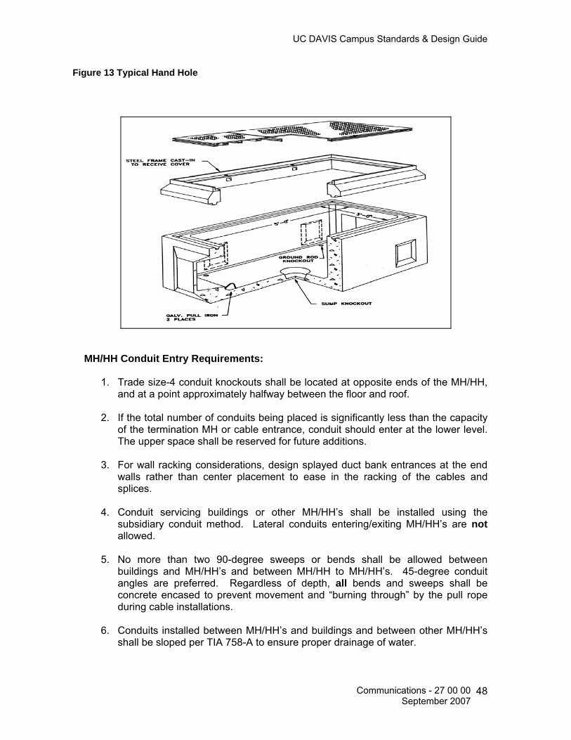
UC DAVIS Campus Standards & Design Guide
Figure 13 Typical Hand Hole
MH/HH Conduit Entry Requirements:
1. Trade size-4 conduit knockouts shall be located at opposite ends of the MH/HH, and at a point approximately halfway between the floor and roof.
2. If the total number of conduits being placed is significantly less than the capacity
of the termination MH or cable entrance, conduit should enter at the lower level. The upper space shall be reserved for future additions.
3. For wall racking considerations, design splayed duct bank entrances at the end
walls rather than center placement to ease in the racking of the cables and splices.
4. Conduit servicing buildings or other MH/HH’s shall be installed using the
subsidiary conduit method. Lateral conduits entering/exiting MH/HH’s are not allowed.
5. No more than two 90-degree sweeps or bends shall be allowed between
buildings and MH/HH’s and between MH/HH to MH/HH’s. 45-degree conduit angles are preferred. Regardless of depth, all bends and sweeps shall be concrete encased to prevent movement and “burning through” by the pull rope during cable installations.
6. Conduits installed between MH/HH’s and buildings and between other MH/HH’s
shall be sloped per TIA 758-A to ensure proper drainage of water.
Communications - 27 00 00 September 2007
48
UC DAVIS Campus Standards & Design Guide
7. All conduits entering buildings shall be plugged with expandable type duct plugs (i.e. Jackmoon) inside the building to prevent rodents, water or gases from entering the building. MH/HH conduits shall be plugged with duct seal material to prevent the entrance of water and gases.
8. Core drilled holes into existing MH/HH’s shall only be accomplished via shop
drawings that clearly identifies the methods and procedures to be used in the coring process. Shop drawings shall to be submitted to Communications Resources for review and comment prior to commencement of work.
Utility Poles for Communications Systems 27 05 46 Aerial Requirements Overhead line construction (aerial electric supply and communications systems) specifications are regulated by the California Public Utilities Commission (CPUC), and shall conform to General Order (G.O.) Number 95. Aerial cable projects shall be designed from engineering drawings approved by Communications Resources. These drawings1 shall include the following information:
• Pole data, including pole class, length, heights of attachments, cross arms and pole steps.
• Cable support strand sizes, down guys, anchors and lead-height ratios. • Span lengths, including appropriate information for slack span constructions,
crossovers, pull-offs, or any other special proposals. • Grounding and bonding instructions. • Construction notes that are applicable to the work being performed. • A legend explaining symbols of all relevant structures. • Cable counts, types and directions of feed. • Terminal counts and splicing details.
Aerial entrances shall be limited to small buildings requiring 100 cable pairs or less for service connections. The following steps shall be taken to design an aerial plant: 1. Select permanent locations for pole lines while considering:
• Future road widening and expansion, existing utilities and road, railway, and
power line crossings. • Safety and convenience of workers and the public.
2. Obtain necessary permits and easements for placing and maintaining pole lines.
1 Reference: UC Davis Campus Standards & Design Guide, Administration Requirements, May 2003.
Communications - 27 00 00 September 2007
49
UC DAVIS Campus Standards & Design Guide
3. Coordinate with other utilities with respect to possible joint use and to minimize inductive interference.
4. Design the pole line for ultimate needs, taking into consideration pole line classification, storm loading, and clearance requirements.
5. Poles shall be of proper strength, class and length to meet the weights of cables, wires, and strands. See Table 6 in CPUC’s G.O. 95 for the proper setting depths for various pole lengths.
6. The most economical span length shall be used: • The span from the last pole to the building shall not exceed 100 feet. • Slack span construction shall be used. • Self-supporting cable shall be considered prior to the design of typical
suspension strand and cable. • Aerial cables shall be placed on the roadside of the pole line.
7. For minimum clearances of drop wires and cables over streets, sidewalks, agricultural areas, railroads, etc., reference the CEC. For additional information, also reference the CPUC’s G.O. 95, Rule 37 and Table 1, the NESC and TIA 758-A.
8. Aerial cables shall enter a building through a conduit with an approved weatherproof service head.
9. Aerial cables shall be labeled upon entering and prior to exiting a building and MH/HH’s in accordance with Specification 09, Outside Plant and Riser Cable Labeling Requirements.
Vibration and Seismic Controls for Communications Systems 27 05 48 Specifications for related facilities shall accommodate the applicable seismic zone 4 or higher requirements.
All cable trays and ladder racking, equipment racks and cabinets shall have seismic bracing as designed by a California Licensed Structural Engineer.
Identification for Communications Systems 27 05 53 This specification is intended to depict the installation of identification labels for horizontal, outside plant/riser cable and termination equipment. Labeling materials identified in this specification are the preferred and recommended manufacturer products required for the complete identification of the installed cable systems.
Communications - 27 00 00 September 2007
50
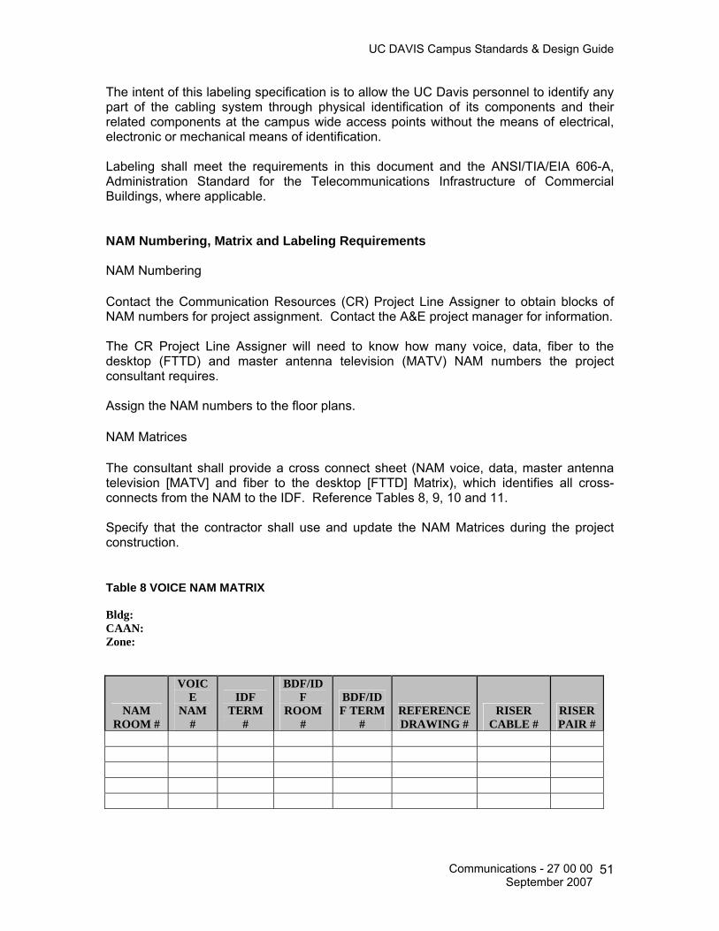
UC DAVIS Campus Standards & Design Guide
The intent of this labeling specification is to allow the UC Davis personnel to identify any part of the cabling system through physical identification of its components and their related components at the campus wide access points without the means of electrical, electronic or mechanical means of identification. Labeling shall meet the requirements in this document and the ANSI/TIA/EIA 606-A, Administration Standard for the Telecommunications Infrastructure of Commercial Buildings, where applicable. NAM Numbering, Matrix and Labeling Requirements NAM Numbering Contact the Communication Resources (CR) Project Line Assigner to obtain blocks of NAM numbers for project assignment. Contact the A&E project manager for information.
The CR Project Line Assigner will need to know how many voice, data, fiber to the desktop (FTTD) and master antenna television (MATV) NAM numbers the project consultant requires.
Assign the NAM numbers to the floor plans.
NAM Matrices
The consultant shall provide a cross connect sheet (NAM voice, data, master antenna television [MATV] and fiber to the desktop [FTTD] Matrix), which identifies all cross-connects from the NAM to the IDF. Reference Tables 8, 9, 10 and 11.
Specify that the contractor shall use and update the NAM Matrices during the project construction. Table 8 VOICE NAM MATRIX Bldg: CAAN: Zone:
NAM ROOM #
VOICE
NAM #
IDF TERM
#
BDF/IDF
ROOM #
BDF/IDF TERM
# REFERENCE DRAWING #
RISER CABLE #
RISER PAIR #
Communications - 27 00 00 September 2007
51

UC DAVIS Campus Standards & Design Guide
Table 9 DATA NAM MATRIX
Bldg: CAAN: Zone:
NAM ROOM#
DATA NAM#
OUTLET NO.
BDF/IDF ROOM#
BDF/IDF TERM#
REFERENCE DRAWING#
Table 10 MATV NAM MATRIX Bldg: CAAN: Zone:
NAM ROOM #
MATV NAM #
OUTLET NO.
BDF/IDF ROOM#
BDF/IDF TERM#
REFERENCE DRAWING#
Table 02-4 FTTD NAM MATRIX Bldg: CAAN: Zone:
NAM ROOM
#
FTTD NAM #
BLDG #
CAAN #
IDF ROOM #
FLOOR #
HOUSING #
POSITION NUMBER IN
HOUSING
CABLE I.D. #
NAM TYPE
MEDIA TYPE
REFERENCE DRAWING NUMBER
Communications - 27 00 00 September 2007
52
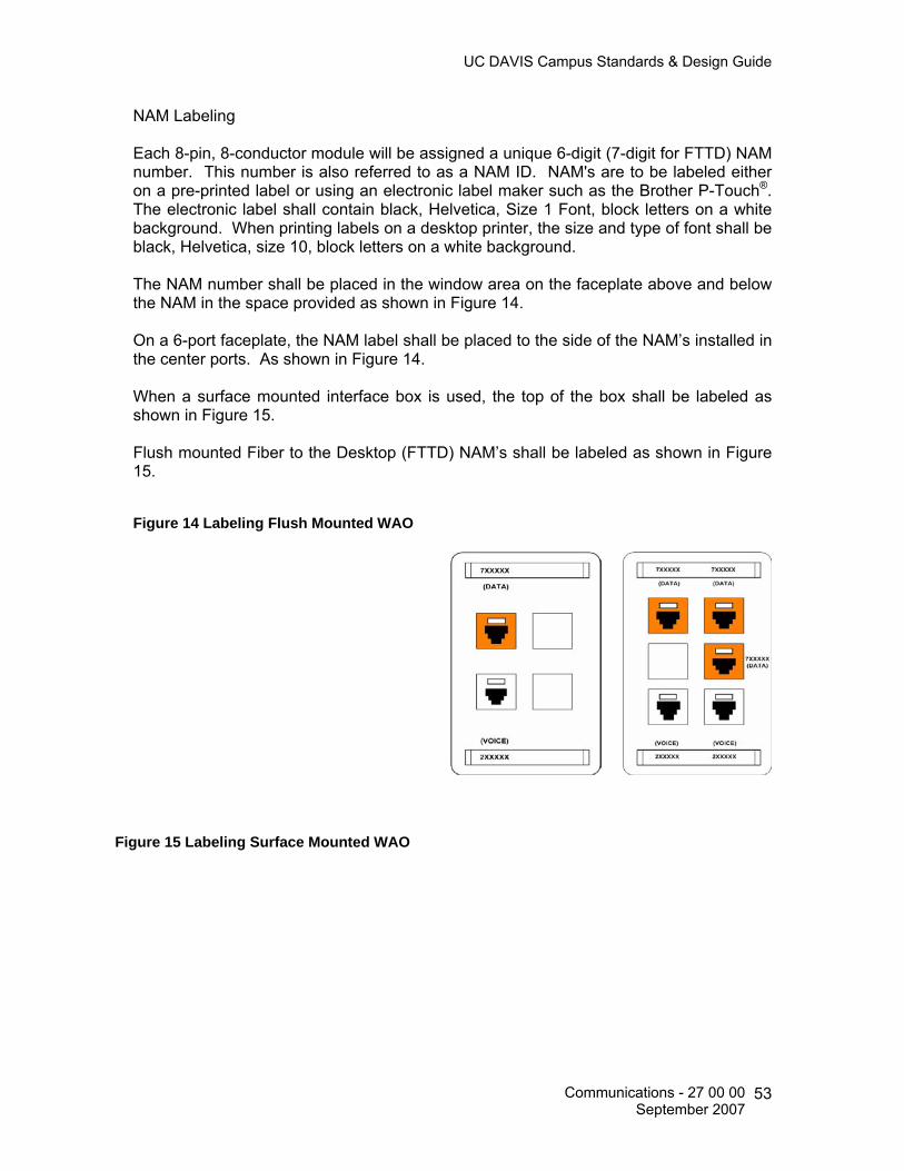
UC DAVIS Campus Standards & Design Guide
NAM Labeling Each 8-pin, 8-conductor module will be assigned a unique 6-digit (7-digit for FTTD) NAM number. This number is also referred to as a NAM ID. NAM's are to be labeled either on a pre-printed label or using an electronic label maker such as the Brother P-Touch®. The electronic label shall contain black, Helvetica, Size 1 Font, block letters on a white background. When printing labels on a desktop printer, the size and type of font shall be black, Helvetica, size 10, block letters on a white background.
The NAM number shall be placed in the window area on the faceplate above and below the NAM in the space provided as shown in Figure 14.
On a 6-port faceplate, the NAM label shall be placed to the side of the NAM’s installed in the center ports. As shown in Figure 14.
When a surface mounted interface box is used, the top of the box shall be labeled as shown in Figure 15.
Flush mounted Fiber to the Desktop (FTTD) NAM’s shall be labeled as shown in Figure 15. Figure 14 Labeling Flush Mounted WAO
Figure 15 Labeling Surface Mounted WAO
Communications - 27 00 00 September 2007
53
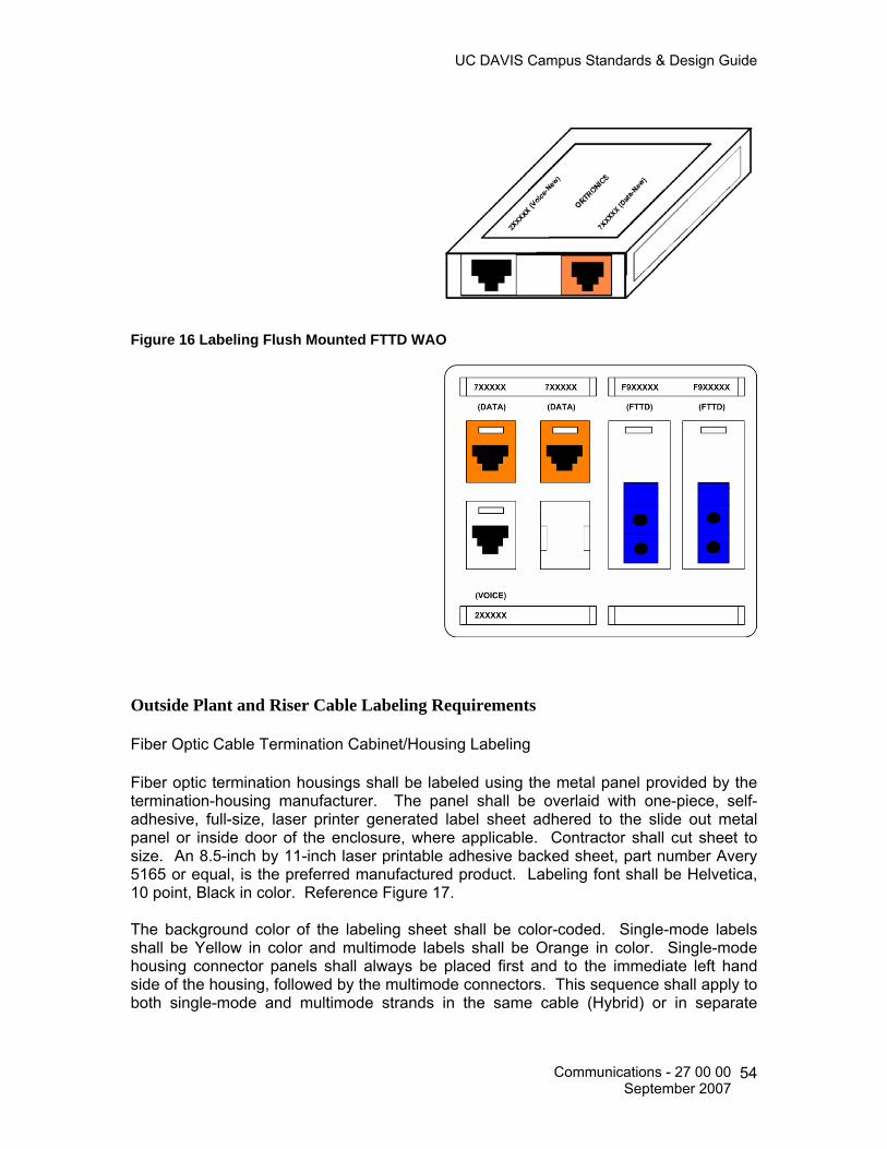
UC DAVIS Campus Standards & Design Guide
Figure 16 Labeling Flush Mounted FTTD WAO
Outside Plant and Riser Cable Labeling Requirements Fiber Optic Cable Termination Cabinet/Housing Labeling Fiber optic termination housings shall be labeled using the metal panel provided by the termination-housing manufacturer. The panel shall be overlaid with one-piece, self-adhesive, full-size, laser printer generated label sheet adhered to the slide out metal panel or inside door of the enclosure, where applicable. Contractor shall cut sheet to size. An 8.5-inch by 11-inch laser printable adhesive backed sheet, part number Avery 5165 or equal, is the preferred manufactured product. Labeling font shall be Helvetica, 10 point, Black in color. Reference Figure 17.
The background color of the labeling sheet shall be color-coded. Single-mode labels shall be Yellow in color and multimode labels shall be Orange in color. Single-mode housing connector panels shall always be placed first and to the immediate left hand side of the housing, followed by the multimode connectors. This sequence shall apply to both single-mode and multimode strands in the same cable (Hybrid) or in separate
Communications - 27 00 00 September 2007
54

UC DAVIS Campus Standards & Design Guide
cables. In wall-mounted housings, the single-mode connectors shall always be placed in the top position, followed by the multimode connectors. Reference Figure 17.
Each fiber optic termination house shall contain only one labeling sheet to identify the fiber optic strands. Multiple labels on a single door shall not be used.
Housing labels shall contain the Capital Asset Account Number (CAAN) for the building (Source) where the fiber optic cable originates, the CAAN for the building (Destination) where the fiber optic strands terminate and the ADF/BDF/IDF identification number where the housing is located.
Fiber strand numbering shall be consistent with the Consecutive Fiber Numbering (CFN) sequence as identified in TIA/EIA 568-B.1. This fiber stand numbering sequence shall be accomplished at each terminated end of the fiber optic cable. The rolling of fiber optic strands, as identified in TIA/EIA 568-B.1 as Reverse Pair Positioning (RPP) shall not be used on the UC Davis campus.
Figure 17 Fiber Optic Closet Connector Housing Labels Example A: 48SM/24MM Cable from CAAN: 4021 to CAAN: 4835 using Figure 09-2 Vertical 568SC Duplex Closet Connector Panel
CAAN: 4021 ADF 3 4835 4835 4835 4835 4835 4835 4835 4835 4835 4835 4835 4835 BDF 1.1
BDF 1.1
BDF 1.1
BDF 1.1
BDF 1.1
BDF 1.1
BDF 1.1
BDF 1.1
BDF 1.1
BDF 1.1
BDF 1.1
BDF 1.1
1/2 7/8 13/14 19/20 25/26 31/32 37/38 43/44 49/50 55/56 61/62 67/68 3/4 9/10 15/16 21/22 27/28 33/34 39/40 45/46 51/52 57/58 63/64 69/70 5/6 11/12 17/18 23/24 29/30 35/36 41/42 47/48 53/54 59/60 65/66 71/72
Example B: 24SM/12MM Cable from CAAN: 4021 to CAAN: 4343/BDF 0.1 and a 24SM/12MM from CAAN: 4021 to CAAN: 4910/BDF 0.1 using Figure 09-2 Vertical 568SC Duplex Closet Connector Panel
CAAN: 4021 ADF 3
4343 4343 4343 4343 4343 4343 4910 4910 4910 4910 4910 4910 BDF 0.1
BDF 0.1
BDF 0.1
BDF 0.1
BDF 0.1
BDF 0.1
BDF 0.1
BDF 0.1
BDF 0.1
BDF 0.1
BDF 0.1
BDF 0.1
1/2 7/8 13/14 19/20 25/26 31/32 1/2 7/8 13/14 19/20 25/26 31/32 3/4 9/10 15/16 21/22 27/28 33/34 3/4 9/10 15/16 21/22 27/28 33/34 5/6 11/12 17/18 23/24 29/30 35/36 5/6 11/12 17/18 23/24 29/30 35/36
Example C: 12SM/12MM Cable from CAAN: 4030 to CAAN: 4566/IDF 1.1 using Figure 09-3 Horizontal 568SC Duplex Closet Connector Panel
Communications - 27 00 00 September 2007
55

UC DAVIS Campus Standards & Design Guide
CAAN: 4835 BDF 1.1 4021 4021 4021 4021 4021 4021 4021 4021 4021 4021 4021 4021
ADF 3 ADF 3 ADF 3 ADF 3 ADF 3 ADF 3 ADF 3 ADF 3 ADF 3 ADF 3 ADF 3 ADF 3 1 3 5 7 9 11 25 27 29 31 33 35 2 4 6 8 10 12 26 28 30 32 34 36
13 15 17 19 21 23 37 39 41 43 45 47 14 16 18 20 22 24 38 40 42 44 46 48
Source CAAN Number (Beginning of Fiber Strand) Destination CAAN Number (End Point of Fiber Strand) ADF/BDF/IDF Number (opposite terminated location of strand) (where applicable) Fiber optic housings containing vertical connector panels Labeling Fiber strand number 1 (Blue) shall occupy fiber port number 1 in the upper most left position of the first duplex bulkhead connector installed in the connector panel placed in the first slot on the left side of the housing.
Fiber strand number 2 (Orange) shall occupy fiber port number 2 of the same duplex bulkhead connector installed in the connector panel. This number 2 port is to the immediate right of fiber port number 1.
All remaining fiber optic strands shall be number consecutively left to right, top to bottom. Reference Figure 18.
Figure 18 Vertical 568SC Duplex Fiber Optic Connector Panel Numbering Sequence
Fiber optic housings containing horizontal connector panels labeling
Communications - 27 00 00 September 2007
56

UC DAVIS Campus Standards & Design Guide
Fiber strand number 1 (Blue) shall occupy fiber port number 1 in the upper most top, left position, of the first duplex bulkhead connector installed in the connector panel placed in the upper most left slot of the housing.
Fiber strand number 2 (Orange) shall occupy fiber port number 2 of the same duplex bulkhead connector installed in the connector panel. This number 2 port is located immediate below fiber port number 1.
All remaining fiber optic strands shall be number consecutively top to bottom, left to right. Reference Figure 19.
Figure 19 Horizontal 568SC Duplex Fiber Optic Connector Panel Numbering Sequence
Fiber Optic Splice Shelf Labeling Fiber optic splice shelves and drawers shall be labeled sequentially from top to bottom using an adhesive backed, labeling stock type of paper printed on a laser printer. Trim the paper to fit the inside door of the splice housing or shelf.
Identify in tabular form the splice tray, position number and the fiber strand spliced at that location. Labeling shall consist of the cable number, the fiber optic strand number and the strand type.
Fiber Optic Cable Sheath Labeling Fiber optic cables located inside buildings shall have their sheaths labeled within 12 inches of the fiber termination housing, the point at which the cable enters and/or exits the room and at one mid-point location when the cable is installed in a cable tray or ladder, as a minimum.
Fiber optic cables located in maintenance holes (MH) shall have their sheaths labeled in at least one location that is visible from grade level. MH’s and HH’s containing splice closures shall be labeled on each side of the splice closure and shall be visible from grade level.
All fiber optic cables shall contain a fiber optic warning tag. All warning tags shall be orange in color and contain large black letters. Tags shall be made from PVC type
Communications - 27 00 00 September 2007
57
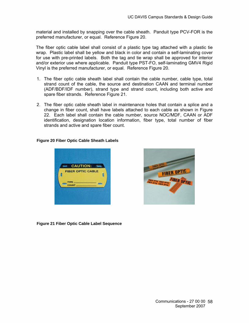
UC DAVIS Campus Standards & Design Guide
material and installed by snapping over the cable sheath. Panduit type PCV-FOR is the preferred manufacturer, or equal. Reference Figure 20. The fiber optic cable label shall consist of a plastic type tag attached with a plastic tie wrap. Plastic label shall be yellow and black in color and contain a self-laminating cover for use with pre-printed labels. Both the tag and tie wrap shall be approved for interior and/or exterior use where applicable. Panduit type PST-FO, self-laminating GMV4 Rigid Vinyl is the preferred manufacturer, or equal. Reference Figure 20.
1. The fiber optic cable sheath label shall contain the cable number, cable type, total
strand count of the cable, the source and destination CAAN and terminal number (ADF/BDF/IDF number), strand type and strand count, including both active and spare fiber strands. Reference Figure 21.
2. The fiber optic cable sheath label in maintenance holes that contain a splice and a change in fiber count, shall have labels attached to each cable as shown in Figure 22. Each label shall contain the cable number, source NOC/MDF, CAAN or ADF identification, designation location information, fiber type, total number of fiber strands and active and spare fiber count.
Figure 20 Fiber Optic Cable Sheath Labels
Figure 21 Fiber Optic Cable Label Sequence
Communications - 27 00 00 September 2007
58

UC DAVIS Campus Standards & Design Guide
Figure 22 Fiber Optic Cable Label Sequence (MH/HH Splice)
Copper Cable Termination Housing Labeling
Communications - 27 00 00 September 2007
59

UC DAVIS Campus Standards & Design Guide
Building entrance terminals shall be labeled with the name of the building, the building zone number, the building CAAN number, the cable pair numbers entering the terminal and the cable pair numbers exiting the terminal (if applicable). Reference Figure 23.
Labels shall be pre-printed using an electronic label maker such as the Brother P-Touch®
or a laser printer. When using an electronic label maker the label shall be 18 point, “font 1” black block letters on a white background. When printing labels on a desktop printer, the size and type shall be black, Helvetica, 10 Font, block letters on a white background. Figure 23 Building
Entrance Terminal Label Sequence
Copper Cable Sheath Labeling Copper cables located inside buildings shall have their sheaths labeled within 12 inches of the termination housing, the point at which the cable enters and/or exits the room and at one mid-point location when the cable is installed in cable tray or ladder rack, as a minimum.
Copper cables located in maintenance holes (MH) and hand holes (HH) shall have their sheaths labeled in at least one location that is visible from grade level. Existing MH’s
Communications - 27 00 00 September 2007
60

UC DAVIS Campus Standards & Design Guide
and HH’s containing splice closures shall be labeled on each side of the splice closure and shall be visible from grade level.
The copper cable label shall consist of a plastic type tag attached with a plastic tie wrap. Plastic label shall be gray in color and have a write-on surface. Labels and tie wraps shall be approved for interior and/or exterior use where applicable. Panduit type CM4S-L8 is the preferred and recommended manufacturer, or equal. Reference Figure 24. The copper cable sheath label shall contain the type of cable, cable number, cable pair count and number of dead cable pairs, if applicable. Reference Figure 25.
Figure 24 Copper Cable Sheath Labels
Figure 25 Copper Cable Label Sequence
Communications - 27 00 00 September 2007
61

UC DAVIS Campus Standards & Design Guide
Commissioning of Communications 27 08 00 Testing Requirements for Copper and Fiber Optic Horizontal Cables General
• Test and document each horizontal cable segment separately. • Test each end-to-end cable link.
The installation contactor shall perform testing on all installed cabling systems. All documented test results shall be provided to the Communications Resources (CR) representative for review and approval. The contractor shall submit these forms with all required information no later than five days after the cables are tested. Prior to testing, the contractor shall notify the CR representative and provide a testing schedule. CR has the right to verify the set-up and procedures of testing instruments and be present during cable certification. The contractor shall provide calibration certifications for testing equipment to be used, with all required information, prior to commencement of testing. UTP Horizontal Voice and Data Cable Testing UC Davis requires that all UTP horizontal station cables be Permanent Link tested with a Level IIE, Level III or later tester for full compliance with TIA/EIA 568-B.1 and B.2, (to include all current addendums) Category 5e specifications, regardless of intended use. Contractor is required to use Cat 6 test cords, by same manufacturer as test equipment, and save all graphs when testing. Test results shall be provided for all conductors of each cable and shall meet Table 12 parameters. Table 12 Permanent Link Testing
Parameter Category 5e Specified Frequency Range 1-100 MHz
Pair to Pair NEXT 32.3 dB Power Sum NEXT 29.3 dB
Insertion Loss 21.0 dB Pair to Pair ELFEXT 18.6 dB Power Sum ELFEXT 15.6 dB
Return Loss 12.0 dB Propagation Delay 498ns @ 10MHz
Delay Skew 44ns Wire Map T568A
Length <295 feet
Communications - 27 00 00 September 2007
62

UC DAVIS Campus Standards & Design Guide
FTTD Horizontal and Riser/Backbone Fiber Cable Testing UC Davis requires that all horizontal single-mode Fiber to the Desktop (FTTD) cables be tested for full compliance with TIA/EIA 568-B.1 and B.3 (to include all current addendums), regardless of intended use. Field-testing instruments for single-mode fiber optic cabling shall meet the requirements of ANSI/TIA/EIA-526-7. Testing Method A and B shall be accomplished. Reference TIA/EIA-568-B.3 for additional test requirements. Fiber optic testing procedures Link attenuation (Power Meter) All horizontal single-mode fiber optic cables shall be tested for link attenuation (i.e. power insertion loss, power meter test) as referenced in TIA/EIA-568-B.1, Section 11.3 and/or University Standards, which is ever more stringent. See Table 13 for proper fiber testing measures. Test the horizontal segment from distribution housing in the Intermediate Distribution Frame (IDF) to the WAO. All fiber optic cables, to include connectors, shall be tested in-line between two reference cables. Once all fiber strands are tested, reverse this procedure and retest. All strands shall be tested in a bi-directional method at both wavelengths with a Power Source and Meter capable of recording and plotting data. One cable shall be attached to the light source and the other to the power meter to measure the dB loss from both connectors, as well as, any dB loss associated with the cable between the connectors. The light source should not be disturbed once the testing begins. TIA/EIA 568-B.1 and TIA/EIA 526-7 outlines the steps required to test single-mode fiber optic cable. Note: Because of the relatively short cable lengths within the horizontal segment (less than 295-feet), the main loss will be connector loss. Ensure that all connectors (on both sides of the mating sleeve) are clean prior to testing. Do not use canned air to clean the connectors or mating sleeves. Some can air products can leave a fluid buildup and/or create a static charge. Optical Time Domain Reflectometer (OTDR) Horizontal cables shall be tested bi-directional and at both wave lengths for dB loss and end-to-end total installed distance with an OTDR. Each trace shall indicate the cable length and dB loss. All OTDR traces shall be accomplished using a manufactured and terminated corning MM/SM, as appropriate, glass launch cable. Make sure you are using the correct fiber
Communications - 27 00 00 September 2007
63
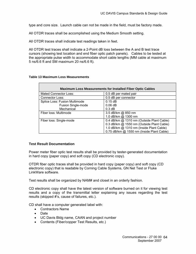
UC DAVIS Campus Standards & Design Guide
type and core size. Launch cable can not be made in the field, must be factory made. All OTDR traces shall be accomplished using the Medium Smooth setting. All OTDR traces shall indicate test readings taken in feet. All OTDR test traces shall indicate a 2-Point dB loss between the A and B test trace cursors (showing test location and end fiber optic patch panels). Cables to be tested at the appropriate pulse width to accommodate short cable lengths (MM cable at maximum 5 ns/6.6 ft and SM maximum 20 ns/6.6 ft). Table 13 Maximum Loss Measurements
Maximum Loss Measurements for Installed Fiber Optic Cables Mated Connector Loss: 0.5 dB per mated pair Connector Loss: 0.5 dB per connector Splice Loss: Fusion Multimode Fusion Single-mode Mechanical
0.15 dB 0.06 dB 0.3 dB
Fiber loss: Multimode 3.5 dB/km @ 850 nm 1.0 dB/km @ 1300 nm
Fiber loss: Single-mode 0.4 dB/km @ 1310 nm (Outside Plant Cable) 0.3 dB/km @ 1550 nm (Outside Plant Cable) 1.0 dB/km @ 1310 nm (Inside Plant Cable) 0.75 dB/km @ 1550 nm (Inside Plant Cable)
Test Result Documentation Power meter fiber optic test results shall be provided by tester-generated documentation in hard copy (paper copy) and soft copy (CD electronic copy). OTDR fiber optic traces shall be provided in hard copy (paper copy) and soft copy (CD electronic copy) that is readable by Corning Cable Systems, GN Net Test or Fluke LinkWare software. Test results shall be organized by NAM# and closet in an orderly fashion. CD electronic copy shall have the latest version of software burned on it for viewing test results and a copy of the transmittal letter explaining any issues regarding the test results (skipped #’s, cause of failures, etc.). CD shall have a computer generated label with:
• Contractors Name • Date • UC Davis Bldg name, CAAN and project number • Contents (Fiber/copper Test Results, etc.)
Communications - 27 00 00 September 2007
64

UC DAVIS Campus Standards & Design Guide
STRUCTURED CABLING 27 10 00 These specifications provide a minimum configuration that shall be used when planning new construction or major remodeling of an existing facility. Communications Resources shall be consulted early during the utilities planning phase of the project since each site may have technical requirements requiring a modification of these specifications.
Communications Equipment Room Fittings 27 11 00
Communications Entrance Protection 27 11 13 Building Entrance Terminals Outside Plant copper cables entering the ADF/BDF/IDF shall be terminated on wall-mounted building entrance protector terminal(s) equipped with gas tube (4B1-EW) protector modules. The 4B1-EW includes heat coils for sneak current protection. Building entrance terminals shall be equipped with full and lockable covers. Building entrance terminals shall not be located directly above the room entrance conduits, slots or sleeves. Terminals shall be mounted in a location on the backboard that shall allow sufficient space for future cable and cross-connect installations. Copper entrance cables up to and including 300 pairs shall be terminated on protected building entrance terminals equipped with a splice chamber and factory installed large 710-type splice modules in the splice chamber (field side) and 110 type terminations on the output (equipment side). Building entrance terminal shall have a lockable cover; Circa model 1880ECS1-100, or equal. Cable shall be blocked with an approved manufactured seal to prevent the gel filled compound from escaping; See Figure 26. Figure 26 Circa 1880ECS1-100
Communications - 27 00 00 September 2007
65

UC DAVIS Campus Standards & Design Guide
Copper entrance cables 301 pairs and larger shall be terminated on individual 100 pair protected terminals equipped with a factory installed, 26AWG swivel cable stub in the splice chamber (field side) and on the output (equipment side): stub-in, stub-out configuration. Cable stubs shall be no shorter than 2 feet in length after installation. Building entrance terminal shall have a lockable cover; Circa model 2000-100, or equal; Figure 27. Figure 27 Circa 2000-100
Factory cable stubs shall be spliced with 25-pair 710-type splice modules to the outside plant copper cable using the fold-back splice method. An indoor rated splice closure and 25-pair 710-type connectors shall be installed and securely mounted to the plywood backboard or existing cable ladder. Indoor closures shall not be encapsulated. In addition to each building entrance terminal installed, a separate 110-type termination block shall be installed adjacent to the building entrance terminal and an indoor rated copper cable installed and terminated, pair for pair, to provide a separate cross-connect point for an up to, but not including 100 pair cable installation. For a 301 pair or larger cable use the factory installed 26AWG swivel cable. Reference Figure 28.
Communications - 27 00 00 September 2007
66

UC DAVIS Campus Standards & Design Guide
Figure 28 Building Entrance Terminal Layout
All terminals shall be labeled in accordance with Section 27 05 53 Identification for Communications Systems and properly grounded to the Telecommunications Grounding Busbar (TGB) in accordance with ANSI-J-STD-607-A.
Communications Cabinets, Racks, Frames and Enclosures 27 11 16
Equipment Racks and Distribution Cabinets UC Davis utilizes seven distinct configurations of distribution equipment racks or cabinets for use in the Equipment Room/Telecommunications Room (ER/TR) (ADF/BDF/IDF): Type 1, Type 2, Type 3, Type 3A, 3B, 3L and 3R. The type and use of each equipment rack or cabinet depends on the ADF/BDF/IDF location, amount of network electronics, termination hardware to be installed, number of Network Access Modules (NAM)’s they serve and the level of security of the location. Table 14 lists the types of distribution equipment racks/cabinets and the application for each type.
Communications - 27 00 00 September 2007
67

UC DAVIS Campus Standards & Design Guide
Table 14 Distribution Equipment Rack/Cabinet Descriptions
Distribution Equipment Racks/Cabinets
Uses
Type 1 96 to 192 NAM’s Type 2 48 to 96 NAM’s Type 3 48 NAM’s or less Type 3A 48 NAM’s or less (wall mounted components) Type 3B 48 NAM’s or less Type 3L 48 NAM’s or less (Lab Cabinet) Type 3R 48 NAM’s or less (Outside Plant equipment enclosure)
Free standing equipment racks shall be used in all ADF/BDF/IDF locations that are secured by a CR lockable door. Equipment racks shall meet the following requirements: 1. One piece 10 gauge welded steel. Nominal height is 7ft (45U). Fits 19 in. rack
mount equipment. Rails must be double sided and tapped on both sides with 12-24 UNC threads in EIA Universal 5/8 – 5/8 – ½ inch vertical mounting hole pattern that matches industry standards and allows quick installation on either side of rack.
2. UL 1863 Tested / Listed to 2,500 lbs static load – max safety factor of 4 – tested to 10,000 lbs. Proof of conformance must be supplied with submittal prior to work.
3. NEBS-Telecordia GR-63-CORE Zone 4: Tested with 500 lb of equipment installed. Dynamic shaker table tested and passed. Proof of conformance must be supplied with submittal prior to work.
4. Approved and Stamped by a Certified State of California Structural Engineer to OSHPD (Office of Statewide Health Planning and Development), CBC (California Building Code) and UBC (Uniform Building Code). Proof of conformance must be supplied with submittal prior to work.
5. Ground holes provided in multiple locations in accordance with BICSI guidelines. Ground symbol pressed into metal as required by NEC (National Electric Code).
6. Single-sided vertical cabling management sections shall be installed with each freestanding rack. Cable management sections shall be of the same manufacturer as the free standing rack to ensure compatibility and quality.
7. Receptacles shall be located on active equipment racks 15” Above the Finished Floor (AFF). Flexible conduit shall be used to prevent the shearing of the conduit during a seismic event.
Free standing cabinets shall be used only in locations that are not securable by a CR lockable door or meet environmental requirements. CR shall approve these areas prior to the design or installation of these cabinets. Reference UCD Policy & Procedure Manual, Section 310-10, Telecommunications Services dated 1/15/02.
Communications - 27 00 00 September 2007
68

UC DAVIS Campus Standards & Design Guide
Cabinets shall meet the following requirements: 1. One piece 10 guage welded steel. Nominal height is 7ft (45U). Fits 19 in. rack
mount equipment. Rails must be double sided and tapped on both sides with 12-24 UNC threads in EIA Universal 5/8 – 5/8 – ½ inch vertical mounting hole pattern that matches industry standards and allows quick installation on either side of rack.
2. UL 1863 Tested / Listed to 2,500 lbs static load – max safety factor of 4 – tested to 10,000 lbs. Proof of conformance must be supplied with submittal prior to work.
3. NEBS-Telecordia GR-63-CORE Zone 4: Tested with 1000 lb of equipment installed. Dynamic shaker table tested and passed. Proof of conformance must be supplied with submittal prior to work.
4. Approved and Stamped by a Certified State of California Structural Engineer to OSHPD (Office of Statewide Health Planning and Development), CBC (California Building Code) and UBC (Uniform Building Code). Proof of conformance must be supplied with submittal prior to work.
5. EIA 310-D listed.
6. Ground holes provided in multiple locations in accordance with BICSI Standards. Ground symbol pressed into metal as required by NEC (National Electric Code).
7. Can be ganged with other 2- and 4-post racks so the sides of the frame can be opened when joined with additional enclosures.
8. Solid sides to close the end panels of single or joined enclosures. Inside panels will be removed when joining enclosures.
9. Solid top panels or top panels equipped with fans. In some cases, side-mount or top-mount air conditioning units may be required.
10. When required, top mounted fans shall provide approximately 535 CFM at 115 VAC. The fan shall include finger guards and power cord. Air filters shall be located in the doors of each unit.
11. A solid bottom panel, 16-gauge, steel plate to enclose the bottom of the cabinet and secure it.
12. The doors to be solid and hinged on the left. Two door configurations shall be hinged on their respective sides. If cabinets are located in a secure, environmentally controlled room, no doors shall be installed to allow for heat dissipation.
13. Lockable handles with a key. Keys shall be common for all cabinet types. Contact CR for key code.
14. Pre-assembled prior to delivery. The pre-assembly instructions shall include any modifications. Cabinets designed to mate with adjoining units shall be shipped as single units to facilitate transportation and movement on small elevators and in other tight quarters.
Communications - 27 00 00 September 2007
69

UC DAVIS Campus Standards & Design Guide
15. Extra screws and miscellaneous hardware for future maintenance requirements shall
be included.
16. Each rack angle assembly shall be adjustable in depth, so that there is a minimum of 6 inches of clearance between the closed door and the face of any installed panel.
17. Cables can enter the cabinets from either the top or bottom. Provisions for cable entry knockouts are required in all designs. 2-inch trade size, T&B XTRAFLEX nonmetallic conduit, shall be used. Plastic connectors, both 90° and 45° angles for bringing cables into the cabinets shall be used. Plastic bushings shall be installed on end of conduits to protect the cable.
18. Sufficient bracing to meet or exceed Zone 4 or higher seismic requirements.
19. Color to be determined by UC Davis.
20. The cabinets shall have the dimensions listed in Table 15. Electrical Requirements A dedicated 120V AC, 20 AMP circuit with a four-plex, NEMA 5-20R spade receptacle outlet shall be located on the backside of each rack at 15-in AFF. Two (2) dedicated 120V AC, 20 AMP circuits with a four-plex, NEMA 5-20R spade receptacle outlet shall be located in each cabinet. They will be placed on the back side of the cabinet: one at 15-inches AFF and the second near the top of the cabinet. Clearances A 3-foot working clearance shall be maintained in the front and in the rear of each equipment rack and cabinet. A 2-foot 6-inch working clearance shall be maintained at one end of the equipment rack or multiple rack assemblies, as a minimum. The front and rear clearance for equipment racks shall be measured from the outermost surface of the electronic equipment and connecting hardware and not from the equipment rack itself since some of these devices may extend beyond the equipment rack. Clearance for cabinets shall be measured from the outermost surface of the cabinet.
Communications - 27 00 00 September 2007
70

UC DAVIS Campus Standards & Design Guide
Equipment Rack and Cabinet Dimensions Table 15 Equipment Rack and Cabinet Dimensions
Type of Termination
Equipment Rack
Dimensions (H x W)
Distribution Cabinet
Dimensions (H × W × D)
ADF 84” × 19” (3 each) 84” × 24” × 32” (3 each)
BDF 84” × 19” (3 each) 84” × 24” × 32” (3 each)
Type 1 IDF 84” × 19” (2 each) 84” × 24” × 32” (2 each)
Type 2 IDF 84” × 19” (1 each) 84” × 24” × 32” (1 each)
Type 3 IDF 28” × 19” (1 each) 28” × 24” × 24” (1 each)
Type 3A 48” x 96” Wall-mounted Plywood Backboard Only
48” x 96” Wall-mounted Plywood Backboard Only
Type 3B Wall-mounted Cabinet 42” x 24.2” x 9.7”
Type 3L 30” × 24” × 24” for use as a lab cabinet
Type 3R 63” x 56” x 46” outdoor enclosure
Note: Overall height of all standing equipment racks and cabinets shall not exceed 84 inches.
Equipment Rack and Cabinet Layouts Area Distribution Frame (ADF) ADF cabinets are used only in ADF locations. Planning for a new ADF shall be coordinated with the Communications Resources, Engineering and Construction Management office.
Communications - 27 00 00 September 2007
71

UC DAVIS Campus Standards & Design Guide
Figure 29 Typical ADF Equipment
Communications - 27 00 00 September 2007
72

UC DAVIS Campus Standards & Design Guide
Figure 30 Typical ADF Cabinet
SD
SD
Smart-UPS
1 4 0 0
Test
AMERICAN POWER CONVERSION
SD
SD
SD
SD
SD
Communications - 27 00 00 September 2007
73

UC DAVIS Campus Standards & Design Guide
BDF/IDF Equipment Racks Figure 31 BDF/IDF Equipment Racks:
Communications - 27 00 00 September 2007
74
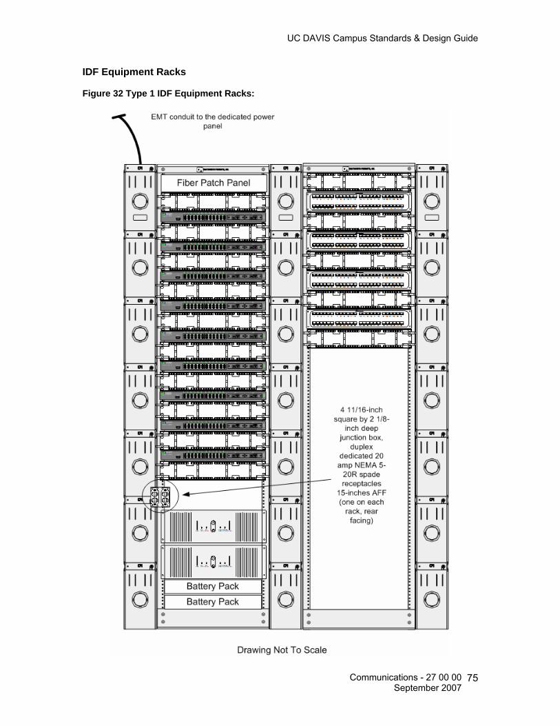
UC DAVIS Campus Standards & Design Guide
IDF Equipment Racks Figure 32 Type 1 IDF Equipment Racks:
Communications - 27 00 00 September 2007
75
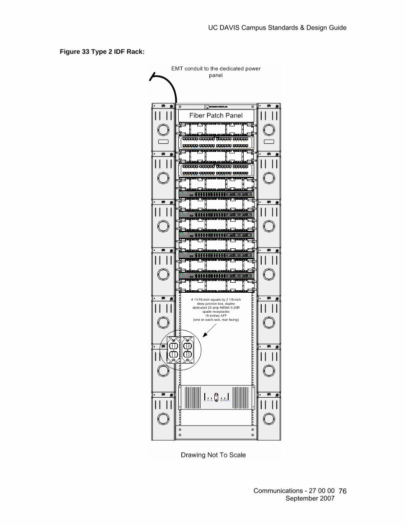
UC DAVIS Campus Standards & Design Guide
Figure 33 Type 2 IDF Rack:
Communications - 27 00 00 September 2007
76

UC DAVIS Campus Standards & Design Guide
Figure 34 Type 3 IDF Rack:
Communications - 27 00 00 September 2007
77

UC DAVIS Campus Standards & Design Guide
The IDF Type 3 wall unit shall be designed to house electronic and electrical components with appropriately placed knockouts for cable entries. A design allowing for 90° pivoting shall be provided. This feature shall allow access to the rear of the enclosure for future maintenance requirements. The hinged component of the wall-mounted cabinet shall support equipment weights up to 100 pounds. Figure 35 Type 3 IDF Wall Mounted Cabinet:
Communications - 27 00 00 September 2007
78

UC DAVIS Campus Standards & Design Guide
The Type 3A is not a cabinet. It defines wall-mounted components on an approved plywood backboard, measuring 48-inches by 96-inches.
Figure 36 Type 3A Wall-Mounted Layout
Communications - 27 00 00 September 2007
79

UC DAVIS Campus Standards & Design Guide
The Type 3B shall be designed for wall mounting. It is typically used in lieu of a Type 3 when 24-inches of depth are not available. The telecommunications space shall have a ¾-inch plywood backboard that is 4-feet by 8-feet. The IDF Type 3B shall be designed to house electrical components with appropriately placed knockouts for cable entries. The IDF Type 3B cabinet is referred as the UCDNet2 Hubbell Remote Equipment Box 42-inch, Hubbell Premise Wiring, catalog number RE4XUCD, Middle Atlantic Products, or equal. See Figure 37. Figure 37 Type 3B Wall-Mounted Cabinet
Communications - 27 00 00 September 2007
80

UC DAVIS Campus Standards & Design Guide
The Type 3L closet (not pictured), also referred to as the “lab cab,” has the same architectural limitation imposed on all “Type 3” cabinets. The maximum number of NAM’s that a “Type 3L” cabinet shall support is 48. In addition, this configuration is applied where local wiring may only extend to within the same room as the cabinet. Typical applications for this configuration are in laboratory or classroom environments where frequent local wiring changes are necessary. All “Type 3L” cabinets shall house the networking components in a cabinet structure for security and management purposes. The telecommunications space shall have a ¾-inch plywood backboard that is at least 3-feet by 4-feet. A ground from the TMBG shall be used on all Type 3L cabinets. Type 3R: 1. The Type 3R outside plant external enclosure (not pictured) is used to house
telephone, data and video system patch panels and equipment. The enclosure shall be water and gas tight (when sealed) and shall be provided with a built-in heating and cooling unit to maintain consistent temperatures within the enclosure at all times.
2. The enclosure shall conform to the following specification:
• The entire enclosure shall meet NEMA type 3R and 4X requirements, and constructed of steel or aluminum panels a minimum of 1/8-inch thick, powder coat painted for exposed conditions. It shall be fitted with lifting eyebolts.
• The doors shall have a three point latching mechanism, external vandal resistant door handle, provision to mount padlocks and each door shall have grounding straps. All doors shall be fitted with a documentation pocket and all external doors shall have Telecordia quarter turn style door locks.
• Overall dimension are not to exceed 63-inches (H) by 56-inches (W) by 46-inches (D).
• Provide all mounting components and accessories and securely fix enclosure to concrete pad.
• Connect built-in heating and cooling systems and power strip to electrical system. A dedicated 125VAC, 20 AMP circuit with a four-plex, NEMA 5-20R-spade receptacle shall be provided on the inside of each cabinet.
• Provide strain relief and cable management inside the enclosure to ensure tidy routing of all cables.
• The enclosure shall consist of three chambers: communications cable entry chamber, electrical chamber (including a built in heat exchanger) and communications chamber (central chamber). Each chamber shall have its own ground busbar.
Communications - 27 00 00 September 2007
81

UC DAVIS Campus Standards & Design Guide
Communications Termination Blocks and Patch Panels 27 11 19 Data Patch Panels. 1. UTP cable patch panels that provide data service to WAO’s shall meet the following
specifications: • High density, 8 port 8P8C module groupings on the front to 110-type IDC PCB
mounted connectors on the back providing termination for 22-26 AWG solid horizontal distribution cables. Panels shall have front and rear labeling designation strips and rear cable management. Terminate 8P8C modules with universal T568A wiring.
2. Patch Panels shall meet specified performance requirements as listed in Table 16.
Performance testing shall be conducted at the component level by a UL certified testing laboratory and include active live channel testing to ensure manufacturer and performance quality. Table 04-1 lists performance requirements tested at 350 MHz.
3. Patch panels shall be manufactured by an ISO 9001 Certified Manufacturer and be fully compliant with ISO/IEC/DIS-11801 standard and meet FCC specifications where applicable. These products shall also be UL® certified, where applicable.
4. The patch panels shall be labeled above the 8P8C module as shown in Figure 38. • Ortronics® Clarity5E, Part number OR-PHD5E8U24 (24 port), or equal. • Ortronics® Clarity5E, Part number OR-PHD5E8U48 (48 port), or equal.
5. Ortronics Cable Management Panel, OR-808044855 or equal is used in conjunction with the above patch panels.
Figure 38 Sample Labeling 24-port Patch Panel.
Communications - 27 00 00 September 2007
82
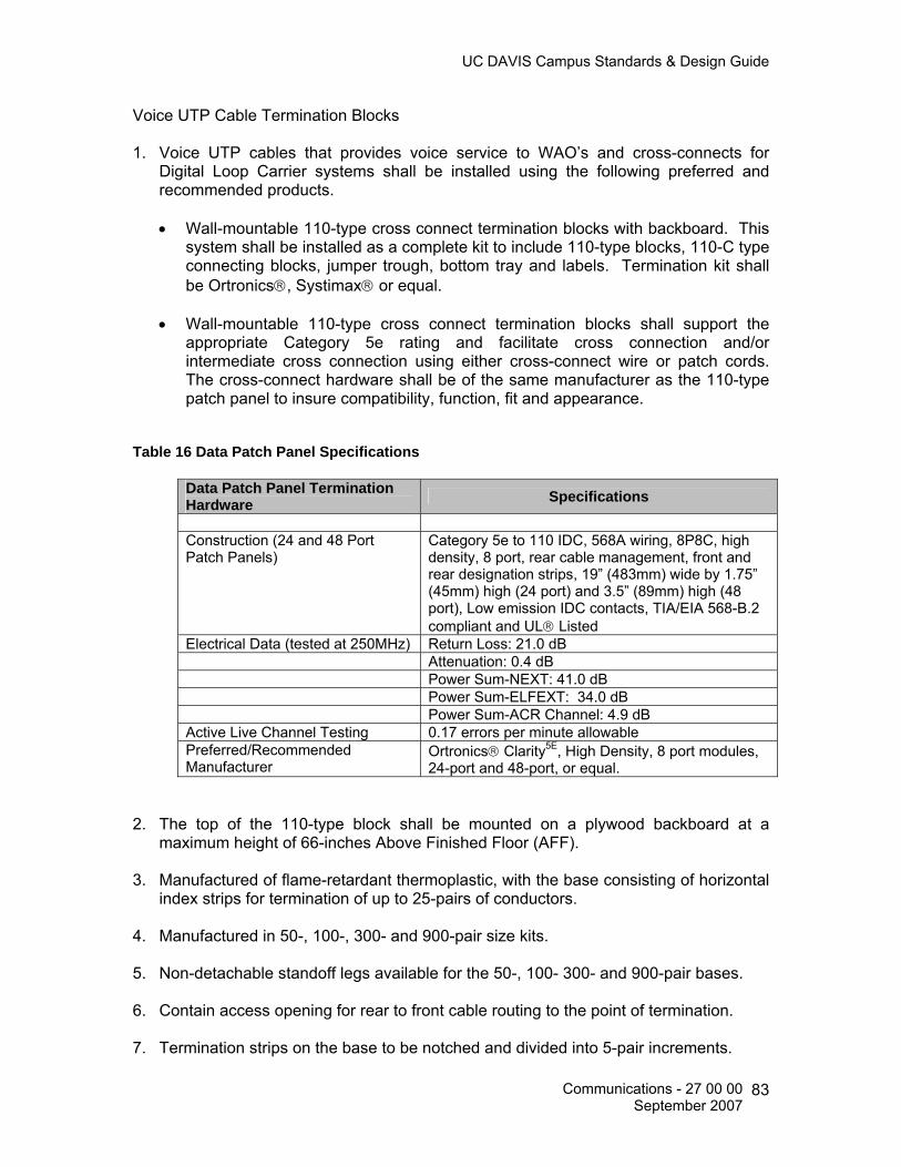
UC DAVIS Campus Standards & Design Guide
Voice UTP Cable Termination Blocks 1. Voice UTP cables that provides voice service to WAO’s and cross-connects for
Digital Loop Carrier systems shall be installed using the following preferred and recommended products. • Wall-mountable 110-type cross connect termination blocks with backboard. This
system shall be installed as a complete kit to include 110-type blocks, 110-C type connecting blocks, jumper trough, bottom tray and labels. Termination kit shall be Ortronics®, Systimax® or equal.
• Wall-mountable 110-type cross connect termination blocks shall support the
appropriate Category 5e rating and facilitate cross connection and/or intermediate cross connection using either cross-connect wire or patch cords. The cross-connect hardware shall be of the same manufacturer as the 110-type patch panel to insure compatibility, function, fit and appearance.
Table 16 Data Patch Panel Specifications
Data Patch Panel Termination Hardware Specifications
Construction (24 and 48 Port Patch Panels)
Category 5e to 110 IDC, 568A wiring, 8P8C, high density, 8 port, rear cable management, front and rear designation strips, 19” (483mm) wide by 1.75” (45mm) high (24 port) and 3.5” (89mm) high (48 port), Low emission IDC contacts, TIA/EIA 568-B.2 compliant and UL® Listed
Electrical Data (tested at 250MHz) Return Loss: 21.0 dB Attenuation: 0.4 dB Power Sum-NEXT: 41.0 dB Power Sum-ELFEXT: 34.0 dB Power Sum-ACR Channel: 4.9 dB Active Live Channel Testing 0.17 errors per minute allowable Preferred/Recommended Manufacturer
Ortronics® Clarity5E, High Density, 8 port modules, 24-port and 48-port, or equal.
2. The top of the 110-type block shall be mounted on a plywood backboard at a
maximum height of 66-inches Above Finished Floor (AFF).
3. Manufactured of flame-retardant thermoplastic, with the base consisting of horizontal index strips for termination of up to 25-pairs of conductors.
4. Manufactured in 50-, 100-, 300- and 900-pair size kits.
5. Non-detachable standoff legs available for the 50-, 100- 300- and 900-pair bases.
6. Contain access opening for rear to front cable routing to the point of termination.
7. Termination strips on the base to be notched and divided into 5-pair increments.
Communications - 27 00 00 September 2007
83
UC DAVIS Campus Standards & Design Guide
8. Clear label holders with the appropriate colored inserts available for the wiring
blocks. The insert labels provided with the product shall contain vertical lines spaced on the basis of circuit size (1-, 3-, 4- or 5-pair) and shall not interfere with running, tracing or removing jumper wire/patch cords. Contact CR for required color code of these labels prior to installation.
9. Bases available with 19-inch panels and high-density frame configurations for rack or wall mounting with cable management hardware.
10. Connecting blocks used for either the termination of cross-connect (jumper) wire or patch cords. The connecting blocks shall be available in 2-, 3-, 4-, and 5-pair sizes. All connecting blocks shall have color-coded tip and ring designation markers and be single piece construction.
11. Connecting blocks with a minimum of 200 re-terminations without signal degradation below standards compliance limit.
12. Support wire sizes: Solid 22-26 AWG (0.64 mm – 0.40 mm). 13. Electrical Specification:
• ANSI/TIA/EIA-568-B.1, B.2 and Category 5e compliant in both design and
performance. • The requirements listed in Table 04-1 shall also be met. • Be UL LISTED 1863, Communications Circuit Accessories, 1995. • 110-type connecting blocks shall be manufactured by an ISO 9001 Certified
Manufacturers, and be fully compliant with ISO/IEC/DIS-11801 standard and meet FCC specifications where applicable. These products shall also be UL® certified, where applicable.
Fiber to the Desktop (FTTD) Patch Panels. FTTD patch panels that provide fiber service to WAO’s shall be terminated using the following preferred and recommended products.
1. Corning Cable Systems® Closet Connector Housings, Rack-mountable, or equal:
• CCH-01U (48 fibers) • CCH-02U (96 fibers) • CCH-03U (144 fibers) • CCH-04U (288 fibers)
2. Corning Cable Systems® Closet Connector Housings, Wall-mountable, or equal: • WCH-02P (24 fibers) • WCH-04P (48 fibers) • WCH-06P (72 fibers) • WCH-08P (96 fibers) • WCH-12P (144 fibers)
Communications - 27 00 00 September 2007
84

UC DAVIS Campus Standards & Design Guide
3. Corning Cable Systems® Closet Connector Housing Panels, Single-mode LC
Adapter Duplex, or equal: • CCH-CP06-A9 • CCH-CP12-A9
4. Corning Cable Systems Unicam® Single-mode LC Ultra Polish connector, Part number 98-200-98, or equal.
5. All rack and wall-mounted fiber optic closet connector housings shall be labeled in accordance with Figure 04-2. The background color of the housing label shall be yellow in color to match the type of fiber strand terminated.
6. Housing and connector panels shall be of the same manufacturer as the fiber optic cable and connectors to ensure proper compatibility, fit, function, appearance and the highest campus wide system performance levels and warranty.
Communications Cable Management and Ladder Rack 27 11 23
Communications Rack Mounted Power Protection and Power Strips 27 11 26
Communications Backbone Cabling 27 13 00 A backbone distribution system provides connection between the Telco Central Office (CO), campus Network Operations Center (NOC) and building ADF’s, BDF’s and IDF’s. A backbone system provides:
• Campus connections interconnecting multiple buildings • Building connections between floors in multistory building
Campus connection consists of Outside Plant (OSP) copper unshielded twisted pair (UTP) cable and/or single-mode fiber optic cable. Building connection consists of Inside Plant (ISP) copper unshielded twisted pair (UTP) and single-mode and multimode fiber cable. Backbone distribution system to be installed in a star topology. UC Davis recognizes a multiple hierarchical level campus backbone design.
Communications - 27 00 00 September 2007
85

UC DAVIS Campus Standards & Design Guide
Communications Copper Backbone Cabling 27 13 13 Building Backbone Inside Plant UTP Copper Cable The building backbone consists of the riser cable and the supporting infrastructure within a building or cluster of buildings that connects the Telecommunications Spaces (ADF/BDF/IDF’s within the ER/TR’s). The riser termination segment shall be designed as illustrated in Figure 39. Table 17 lists the following color codes for cross connect fields. Table 6-3 shall be used to identify horizontal and riser cables in accordance with TIA/EIA 606-A. Table 17 Cross Connect Field Color Codes
TERMINATION TYPE COLOR COMMENTS Demarcation point Orange Central office connection
Network connections Green User side of Central Office connection Common equipment PBX, Host, LANs
Purple
Connections to PBX, mainframe computer, LAN, multiplexer
First level backbone
Blue
Terminations of building backbone cable connecting MC to IC’s
Second level backbone
Gray
Terminations of building backbone cable connecting IC to HC’s
Horizontal White Terminations of horizontal cable in TS Campus backbone Green Termination of backbone cable between buildings
Miscellaneous Yellow Alarms, security or energy management Key systems Red Connections to key telephone systems
Communications - 27 00 00 September 2007
86

UC DAVIS Campus Standards & Design Guide
Figure 39 Star building backbone
Type and Size of Copper Backbone Riser Cable Copper Riser Cable Specifications The type of riser cable shall meet the following requirements: 1. UL 444 and 1666, ANSI/TIA/EIA 568-B.2, FCC Part 68, Telecordia GR-111,
Category 3, listed as CMR.
2. The type of riser cable shall be ARMM. This type of cable can be placed in vertical shafts without the use of conduit. Filled-core outside plant cable shall not be used for interior backbone cable.
3. The riser cable is labeled based on a cable number assigned by Communications Resources Project Line Assigner. The cable pair count shall also be included in the label.
4. ARMM riser cables shall be grounded and bonded in accordance with ANSI-J-STD-607-A requirements, as applicable.
5. Plenum rated, multi-pair copper cables shall be installed in horizontal (cable tray) installations between the BDF and IDF, where required.
Communications - 27 00 00 September 2007
87

UC DAVIS Campus Standards & Design Guide
6. Reference Division 27 11 19, Communications Termination Blocks and Patch
Panels, for riser cable termination hardware. Size Copper Riser Cable The size of the riser cable is a function of the number of WAO’s supported by the IDF. The minimum number of copper riser cable pairs required for each voice NAM = 2 pairs, three (3) or more voice NAMs = 1.5 pairs per NAM. Riser cables shall be sized to the next larger, even pair size (i.e. 100, 200, 300, etc). Outside Plant UTP Copper cable Filled core (waterproofing compound) cable shall be used for underground and direct-buried cable installations. Filled cable preserves the integrity of the cable by providing physical protection against moisture penetration and seepage. Aerial cable installations require an air-core type of cable. Direct-buried cable installations require an armored sheath type of cable to resist rodent and penetration type damage. All outside plant cable shall be Plastic Insulated Conductors (PIC) and the cable jacket shall be marked with the cable length, cable code, date and manufacturer. The following standard designations for copper exchange cable have been assigned by the Rural Utilities Services (RUS): • PE-39 refers to filled cable with solid polyolefin insulation and is suitable for conduit
and direct-buried applications. Cable shall meet ANSI ICEA 7CFR-1755-039 and 390 specifications.
• PE-89 refers to filled cable with formed polyolefin insulation and is suitable for conduit and direct-buried applications. Cable shall meet ANSI ICEA 7CFR-1755-089 and 890 specifications.
Minimum bend radius shall be maintained during and after the installation phase. The minimum bend radius during installation is 10 times the outside diameter of the cable and 8 times the outside diameter after installation.
Communications - 27 00 00 September 2007
88
UC DAVIS Campus Standards & Design Guide
Communications Copper Cable Splicing and Terminations 27 13 13.13 Cable Splicing Methods and Splice Closures Copper Cable Splice Methods Copper telephone cables shall be spliced using a 710-type, 25-pair, large size, gray in color connector (710SC1-25, 710SD1-25, and 710TC1-25) for underground, direct-buried, aerial and building terminal splices. 710-type connectors shall be 3M-type or equal. All splices shall be accomplished using the conductor fold-back method to ease future splicing and maintenance efforts. Copper Cable Splice Closures Copper cable splices (Aerial, Underground, and Direct-buried) shall be sealed using a bolt together, washer-less, stainless-steel type of closure with field adaptable/drillable/reusable 1, 2 and 3 section end plates to match the existing cable plant. Closure shall be Preformed Line Products® (PLP) or equal. No known equal.
The closure shall be sized to allow sufficient interior space for the fold-back method of splicing and to allow for the addition of future bridge spliced cables. The closure shall be air pressure tested (flash-tested) upon installation and shall not be filled with encapsulant. All splice closures shall be properly supported, racked and lashed to the MH racks. Closures shall be supported by their own individual cable steps, in addition to the steps used to support the cable itself. All splice closures shall be properly grounded to the MH grounding and bonding system. All splices shall be inspected by a Communication Resources designated representative prior to the completion and sealing of the splice. All copper cables shall be labeled in accordance with Division 27 05 53 Identification for Communication Systems, outside plant and riser cable labeling requirements.
Communications Optical Fiber Backbone Cabling 27 13 23 Type of Fiber Optic Riser Cable The type of riser cable shall meet the following requirements: 1. Conform to CEC Article 770 and comply with the State of California fire codes as
interpreted by the Campus Fire Marshal’s office.
Communications - 27 00 00 September 2007
89

UC DAVIS Campus Standards & Design Guide
2. The type of riser cable shall be UL listed OFNR rated. This type of cable can be
placed in vertical shafts without the use of conduit. Filled-core Outside Plant cable shall not be used for interior backbone cable.
3. The riser cable is labeled based on a cable number assigned by Communications Resources. The fiber strand numbers shall also be included in the label.
4. The cable shall be of the same manufacturer as the fiber optic termination equipment to ensure fit, function, system compatibility, performance and warranty. The campus recommended and preferred cable is the Corning Cable Systems® Infinicor™ MIC® type cable.
Reference Division 27 11 19 Communications Termination Blocks and Patch Panels for termination hardware. Table 4 shows the maximum conduit fill ratio requirements for riser cables. Size Fiber Optic Riser Cable The size of the hybrid riser fiber optic cable is a function of the number of data NAM’s served by the IDF and the type of IDF. The recommended minimum number of fiber strands for each type of IDF is shown in Table 18. Each IDF hybrid fiber cable shall be comprised of single-mode and multimode fiber strands. Actual fiber type and strand counts shall be based upon the requirements of each project. Contact CR for fiber strand information. Table 18 Recommended Size of IDF Riser Fiber Optic Cable
Number of Data NAM’s Number of Fiber Strands Required
24 data NAM’s or less 12 strands 25 to 48 data NAM’s 24 strands 49 to 96 data NAM’s 48 strands
97 data NAM’s and up 72 strands Outside Plant Fiber Optic cable Loose Tube dry cable with waterblocking technology cable by use of a water-swellable tape shall be used for underground installations. A loose tube traditional filled core flooding compound cable shall be used for direct-buried fiber optic cable installations. Waterblocking cable preserves the integrity of the cable by providing physical protection against moisture penetration and seepage. Loose tube fiber optic cable is the preferred and recommended cable for outside plant applications at UC Davis.
Communications - 27 00 00 September 2007
90

UC DAVIS Campus Standards & Design Guide
Direct-buried fiber optic cable requires an armored sheath to resist rodent and penetration type damage.
Indoor/Outdoor and outside plant fiber optic cable construction specifications: 1. OSP cable shall be a dry cable with a water-swellable tape versus a traditional gell-
filled flooding compound.
2. Optical fibers shall be placed inside a standard 3.0 mm buffer tube.
3. Each buffer tube shall contain up to 12 fibers.
4. The fibers shall not adhere to the inside of the buffer tube.
5. Each fiber shall be distinguishable by means of color-coding in accordance with TIA/EIA-598-B, “Optical Fiber Cable Color Coding.”
6. The fibers shall be colored with ultraviolet (UV) curable inks.
7. Buffer tubes containing fibers shall be color-coded with distinct and recognizable colors in accordance with TIA/EIA-598-B, “Optical Fiber Cable Color Coding.”
8. Buffer tube colored stripes shall be inlaid in the tube by means of co-extrusion when required. The nominal stripe width shall be 1 mm.
9. For dual layer buffer tube construction cables, standard colors are used for tubes 1 through 12 and stripes are used to denote tubes 13 through 24. The color sequence applies to tubes containing fibers only and shall begin with the first tube. If fillers are required, they shall be placed in the inner layer of the cable. The tube color sequence shall start from the inside layer and progress outward.
10. In buffer tubes containing multiple fibers, the colors shall be stable across the
specified storage and operating temperature range and not subject to fading or smearing onto each other or into the gel filling material. Colors shall not cause fibers to stick together.
11. The buffer tubes shall be resistant to external forces and shall meet the buffer tube cold bend and shrink back requirements of 7 CFR 1755.900.
12. Fillers may be included in the cable core to lend symmetry to the cable cross-section where needed. Fillers shall be placed so that they do not interrupt the consecutive positioning of the buffer tubes. In dual layer cables, any fillers shall be placed in the inner layer. Fillers shall be nominally 3.0 mm in outer diameter.
13. The central anti-buckling member shall consist of a dielectric, glass reinforced plastic (GRP) rod. The purpose of the central member is to prevent buckling of the cable. The GRP rod shall be over coated with a black colored thermoplastic when required to achieve dimensional sizing to accommodate buffer tubes/fillers.
Communications - 27 00 00 September 2007
91

UC DAVIS Campus Standards & Design Guide
14. Each buffer tube shall be filled with a non-hygroscopic, non-nutritive to fungus, electrically non-conductive, homogenous gel. The gel shall be free from dirt and foreign matter. The gel shall be readily removable with conventional nontoxic solvents.
15. Buffer tubes shall be stranded around the dielectric central member using the reverse oscillation, or “S-Z”, stranding process. Water blocking yarn(s) shall be applied longitudinally along the central member during stranding.
16. Two polyester yarn binders shall be applied contra-helically with sufficient tension to secure each buffer tube layer to the dielectric central member without crushing the buffer tubes. The binders shall be non-hygroscopic, non-wicking and dielectric with low shrinkage.
17. For single layer cables, a water blocking tape shall be applied longitudinally around the outside of the stranded tubes/fillers. The tape shall be held in place by a single polyester binder yarn. The water blocking tape shall be non-nutritive to fungus, electrically non-conductive and homogenous. It shall also be free from dirt and foreign matter.
18. For dual layer cables, a second (outer) layer of buffer tubes shall be stranded over the original core to form a two-layer core. A water blocking tape shall be applied longitudinally over both the inner and outer layer with each being held in place with a single polyester binder yarn. The water blocking tape shall be non-nutritive to fungus, electrically non-conductive and homogenous. It shall also be free from dirt and foreign matter.
19. The cable shall contain at least one ripcord under the sheath for easy sheath removal of all-dielectric cable. The cable shall contain at least one ripcord under the inner sheath and under the steel armor for armored cable. The ripcord color shall be orange for non-armored sheaths and yellow for armored sheaths.
20. Dielectric yarns shall provide tensile strength.
21. The high tensile strength dielectric yarns shall be helically stranded evenly around the cable core.
22. All-dielectric cables (non-armored) shall be sheathed with medium density polyethylene (MDPE). The minimum nominal jacket thickness shall be 1.4 mm. Jacketing material shall be applied directly over the tensile strength members and water blocking tape. The polyethylene shall contain carbon black to provide ultraviolet light protection and shall not promote the growth of fungus. See Figure 40.
Communications - 27 00 00 September 2007
92

UC DAVIS Campus Standards & Design Guide
Figure 40 Dielectric OSP Fiber Optic Cable
23. Armored cables shall have an inner sheath of MDPE. The minimum nominal jacket
thickness of the inner sheath shall be 1.0 mm. The inner jacket shall be applied directly over the tensile strength members and water blocking tape. A water blocking tape shall be applied longitudinally around the outside of the inner jacket. The armor shall be a corrugated steel tape, plastic-coated on both sides for corrosion resistance, and shall be applied around the outside of the water blocking tape with an overlapping seam with the corrugations in register. The outer jacket shall be applied over the corrugated steel tape armor. The outer jacket shall be a MDPE with a minimum nominal jacket thickness of 1.4 mm. The polyethylene shall contain carbon black to provide ultraviolet light protection and shall not promote the growth of fungus. See Figure 41.
Figure 41 Armored OSP Fiber Optic Cable
Communications - 27 00 00 September 2007
93
UC DAVIS Campus Standards & Design Guide
24. The MDPE jacket material shall be as defined by ASTM D1248, Type II, Class C and Grades J4, E7 and E8.
• The jacket or sheath shall be continuous, free from pinholes, splits, blisters or
other imperfections.
• The cable jacket shall contain no metal elements and shall be of a consistent and uniform thickness. Cable jackets extruded under high pressure are not acceptable. The jacket shall be smooth, as is consistent with the best commercial practice. The jacket shall provide the cable with a tough, flexible, protective coating able to withstand the stresses in normal installation and service.
• Cable jackets shall be marked with manufacturer’s name or file number,
sequential meter or foot markings, month and year, or quarter and year of manufacture, and a telecommunications handset symbol, as required by Section 350G of the National Electrical Safety Code® (NESC®), fiber count, fiber type, flame rating (where applicable) and listing marking. The actual length of the cable shall be within –0/+1% of the length markings. The print color shall be white, with the exception that cable jackets containing one or more coextruded white stripes shall be printed in light blue. The height of the marking shall be approximately 2.5 mm.
• The cable jacket of a cable containing two different fiber types (hybrid
construction) shall be marked to indicate quantity of each fiber type, identity of each fiber type and the fiber sequence.
• When required, cables shall be sheathed with flame-retardant polyvinyl chloride
(PVC). Jacketing material shall be applied directly over the tensile strength members and water blocking tape. The PVC shall contain carbon black to provide ultraviolet light protection and shall not promote the growth of fungus.
• When required, un-armored, all-dielectric cables shall be listed OFNR and shall
be described previously.
• When required, interlocking armored cables shall be as described previously in this section, but shall also include an interlocking aluminum armor applied helically around the outside of the cable jacket. The interlocking armor may be left un-jacketed or may have a PVC outer jacket. The color of the armor jacket (if specified) shall match the jacket color of the optical fiber cable located inside the armor. The armor for these cables shall be comparable to liquid tight flexible metal conduit if jacketed or flexible metal conduit if not jacketed. The cable used in this application shall be listed OFCR. Cables with interlocking armor shall be available in fiber counts up to 120 fibers.
Communications - 27 00 00 September 2007
94
UC DAVIS Campus Standards & Design Guide
• If the initial marking fails to meet the specified requirements (i.e. improper text statement, color, legibility or print interval), the cable may be remarked using a contrasting alternate color. The numbering sequence shall differ from the previous numbering sequence, and a tag shall be attached to both the outside end of the cable and to the reel to indicate the sequence of remarking. The preferred remarking color shall be yellow, with the secondary choice being blue.
25. The maximum pulling tension shall be 2700 N (600 lbf) during installation (short
term) and 890 N (200 lbf) for Altos® cable and 600 N (135 lbf) for FREEDM® cable, long term installed.
26. Be manufactured by a TL 9000 and ISO 9001 Certified Manufacturer. Note: Indoor/outdoor rated cable shall be installed in those locations where the indoor exposed cable distance from the entry point to the termination or splice location exceeds 50-feet.
Table 19 Single-mode Cable Specifications
Single-mode Fiber Optic Cable Description Specification
Maximum Attenuation: (dB/km) 0.4 @ 1310nm 0.3 @ 1550nm Gigabit Ethernet Distance Guarantee: (meter) 5000 @ 1310nm
Temperatures: (Operation) -40 to +70°C (-40 to +158°F) All Dielectric -40 to +70°C (-40 to +167°F) Armored Maximum Tensile Load: Short Term 2700N (600 lbf)
Long Term: 890N (200 lbf) ALTOS® 600N (135 lbf) FREEDM®
Approvals and Listings RUS 7 CFR 1755.900
Design and Test Criteria ANSI/ICEA S-87-640 (ALTOS®), ANSI/ICEA S-104-696 (FREEDM®)
NEC Listing Article 770 Preferred and Recommended Manufacturer: Corning Cable Systems® ALTOS®, FREEDM®, or equal.
Communications - 27 00 00 September 2007
95

UC DAVIS Campus Standards & Design Guide
Table 20 Multimode Cable Specifications
Multimode Fiber Optic Cable Description Specification Maximum Attenuation: (dB/km) 3.5 @ 850nm 1.0 @ 1300nm Minimum LED Bandwidth (MHz/km) 200 @ 850nm, 500 @ 1300nm Minimum RML Bandwidth (MHz/km) 385 @ 850nm Gigabit Ethernet Distance Guarantee: (meter) 500 @ 850, 1000 @ 1300 Temperatures: (Operation) -40 to +70°C (-40 to +158°F) All Dielectric -40 to +70°C (-40 to +167°F) Armored Maximum Tensile Load: Short Term: 2700N (600 lbf)
Long Term: 890N (200 lbf) (ALTOS®) 600N (135 lbf) (FREEDM®)
Approvals and Listings RUS 7 CFR 1755.900 Design and Test Criteria ANSI/ICEA S-87-640 (ALTOS®)
ANSI/ICEA S-104-696 (FREEDM®) Preferred and Recommended Manufacturer: Corning Cable Systems® ALTOS®, FREEDM®, or
equal. Minimum bend radius shall be maintained during and after the installation phase. The minimum bend radius during installation is 15 times the outside diameter of the cable and 10 times the outside diameter after installation. The recommended minimum number of fiber strands for each type of TS is shown in Table 21. Table 21 Recommended Size of OSP Fiber Optic Cable for building distribution
Type of Telecommunications Space Number of Fiber Strands Required
ADF 144 strands BDF 72 strands IDF See Table 6-4 for strand count
Communications Optical Fiber Splicing and Terminations 27 13 23.13
Fiber Optic Cable Splice Methods 1. Confer with Communication Resources when designing the outside plant cable layout. 2. Should a field splice be required, both multimode and single-mode OSP fiber cables shall be spliced using a CR approved fusion splicing machine only. Mechanical splices shall not be allowed. Heat shrink type fusion protectors with a strength member shall be used for all fusion splices.
Communications - 27 00 00 September 2007
96

UC DAVIS Campus Standards & Design Guide
3. The larger 12-strand 12-inch size splice trays shall be used for both multimode and single-mode splices to allow additional space for retaining fiber loops and controlling bend radius. 4. A minimum of 30-feet of fiber optic cable (slack) shall be provided in the MH after splicing activities are completed. This slack is required to allow splicing activities to take place outside of the MH and in a controlled environment (e.g. splicing trailer/van). This slack shall be properly stored and lashed to the MH racks and shall not interfere with existing cables and splice closures. 5. All splices shall be inspected by a Communication Resources designated representative prior to sealing the splice. Fiber Optic Splice Closures: 1. Fiber optic cable splices shall be sealed using a hard plastic, bolt together, re-useable/re-sealable type of fiber optic cable closure. Closure shall be Preformed Line Products® Coyote®, Corning Cable Systems®, or equal. 2. Closure shall allow manufacturer’s recommended slack (typically 8 to 10 ft) within the closure to facilitate present and future fiber splicing and maintenance activities. 3. All splice closures shall be properly supported, racked and lashed to the MH racks. Closures shall be supported by their own individual cable steps, in addition to the steps used to support the cable itself. 4. All splice closures shall be properly grounded to the MH grounding system, when applicable. 5. All Fiber Optic cables shall be labeled in accordance with Division 27 05 53 Identification for Communication Systems. Fiber Optic Connectors Fiber optic cable for outside plant and riser/backbone installations shall be fusion spliced to factory made 568SC Ultra PC Polish type pigtails at the ADF/BDF/IDF:
• Corning Cable Systems® 568SC Duplex Ceramic Ferrule, 1 meter Multimode cable assembly, or equal.
• Corning Cable Systems® 568SC Ultra PC Polish, 1 meter Single-mode cable assembly, or equal.
Closet Connector and Splice Housings
Fiber distribution cabinets shall be wall-mounted or rack-mounted in either welded steel equipment racks or enclosed data cabinets.
All fiber optic connectors, termination housings and hardware shall be of the same manufacturer as the installed cable to ensure campus wide network system
Communications - 27 00 00 September 2007
97

UC DAVIS Campus Standards & Design Guide
compatibility, optimum performance, fit, function, appearance and warranty. The preferred and recommended type and manufacturer of fiber optic connectors, termination housings and connector panels shall be Corning Cable Systems®, or equal. If substitutions are requested by the consultant/contractor, then documented and demonstrated equivalency shall be provided to CR for their review.
568SC type fiber connector panels can be either Duplex 6 or 12 ports depending upon the availability of termination space within the cabinet, and shall be of the same manufacturer as the housing to ensure fit, function, appearance and warranty. Size of connector panel installed shall require the approval of Communications Resources.
All loose-tube outside plant fiber optic cables terminated with field installable unicam connectors shall have a buffer tube fan out kit installed prior to the installation of fiber connectors. Fiber distribution cabinets (rack and wall-mounted closet connector housings) shall be labeled in accordance with Division 27 05 53 Identification for Communication Systems.
The fiber distribution cabinets shall be configured with jumper troughs to aid in jumper management.
Fiber optic cable for outside plant and riser/backbone installations shall be terminated in rack or wall mounted fiber optic termination housings:
1. Corning Cable Systems® Closet Connector and Splice Housings (CCS), Rack-
mountable, or equal:
• CCS-01U (24 fibers) • CCS-03U (48 fibers)
2. Corning Cable Systems® Closet Connector Housings (CCH), Rack-mountable, or
equal:
• CCH-03U (72 fibers) • CCH-04U (144 fibers)
3. Corning Cable Systems® Closet Splice Housings (CSH), Rack-mountable, or equal:
• CJH-02U (96 fibers) • CSH-03U (288 fibers) • CSH-05U (528 fibers)
4. Corning Cable Systems® Wall-Mountable Closet Housing (WCH), Wall-mountable,
or equal:
• WCH-02P (24 fibers) • WCH-04P (48 fibers) • WCH-06P (72 fibers) • WCH-08P (96 fibers) • WCH-12P (144 fibers)
Communications - 27 00 00 September 2007
98

UC DAVIS Campus Standards & Design Guide
Rack-mountable Connector Housing Splice Trays, or equal:
• M67-112 (Type 2S, 24 fusion splices) Wall-mountable Closet Housing Splice Tray Holders and Splice Trays: 1. Splice Tray Holders, or equal:
• WCH-SPLC-2P (2 trays, max 12 fusion splices) • WCH-SPLC-4-8 (8 trays, max 48 fusion splices) • WCH-SPLC-12 (12 trays, max 72 fusion splices)
Splice Trays, or equal:
• M67-068 (Type 2R, 6 fusion splices) Fiber optic cable for outside plant and riser/backbone installations shall be terminated on Duplex 568SC type connector panels at the ADF/BDF/IDF:
• Corning Cable Systems®, CCH-CP06-91 (Preloaded 3 duplex connectors,
Multimode, Composite Insert, Beige, for connecting 6 SC connectors), or equal.
• Corning Cable Systems®, CCH-CP06-59 (Preloaded 3 duplex connectors, Single-mode, Ceramic Inserts, Blue for connecting 6 SC connectors), or equal.
• Corning Cable Systems®, CCH-CP12-91 (Preloaded 6 duplex connectors,
Multimode, Composite Insert, Beige, for connecting 12 SC connectors), or equal.
• Corning Cable Systems®, CCH-CP12-59 (Preloaded 6 duplex connectors, Single-mode, Ceramic Insert, Blue, for connecting 12 SC connectors), or equal.
Communications Coaxial Backbone Cabling 27 13 33 Reference MASTER ANTENNA TELEVISION (MATV) SYSTEM Section 27 43 00. Communications Coaxial Splicing and Terminations 27 13 33.13
Communications - 27 00 00 September 2007
99

UC DAVIS Campus Standards & Design Guide
Communications Horizontal Cabling 27 15 00 UC Davis recognizes two types of cables for use in the horizontal segment: Unshielded Twisted Pair (UTP) and single-mode (SM) fiber optic cable.
1. UTP cable shall be 4-pair, 24 AWG, solid conductor cabling that meets ANSI/TIA/EIA 568-B.1 and B.2 cabling specifications for Category 5e cable, to include any/all current Addendums and Bulletins and shall meet specified specifications and performance requirements.
2. Fiber optic cable shall be a minimum of 4-strands, single-mode, 8.3/125μm, tight-
buffered, indoor cable.
The standard cable sheath colors of horizontal copper UTP cable installed on the UC Davis campus are BLUE for Data and WHITE for Voice. Cable shall be manufactured, tested, certified and meet the performance requirements listed in Table 22. Performance requirements shall be tested at the 250 MHz level, as a minimum. Performance testing shall be conducted at the component level by a UL certified testing laboratory and include active live channel testing to ensure manufacturer and performance quality. Documentation of this performance test shall be provided to CR prior to installation. All conductive cable, fiber optic, radio and television, community antenna and network-powered broadband communications systems and associated components shall comply with the following 2001 (or the most current edition at the time of design) California Electric Code (CEC) articles:
• Article 770 Optical Fiber Cables and Raceways • Article 800 Communications Circuits • Article 810 Radio and Television Equipment • Article 820 Community Antenna Television and Radio Distribution • Article 830 Network Powered Broadband Communications Systems
In addition, all fiber optic cabling shall meet or exceed OFN-FT4 (Non-plenum) and OFN-FT6 (Plenum) requirements. All cabling shall be UL Listed Type CMP, OFNR or OFNP if it is placed in air-handling plenums or risers without conduit. The cable sheath shall be marked with the UL listing. Horizontal cables shall not be spliced, nor will these cables contain manufacturer splices. Horizontal cables shall not be connected directly to telecommunications or network equipment. Suitable termination hardware (i.e. patch panels and 110-type punch-down blocks) and factory-manufactured patch cords shall be used to make this connection. Cross-connect jumper wire shall be used for voice and fire alarm circuits only.
Communications - 27 00 00 September 2007
100

UC DAVIS Campus Standards & Design Guide
Patch cords shall be manufactured by the same manufacturer as the data patch panels and information modules to ensure compatibility, performance and warranty meet or exceed Category 5e requirements and specific performance requirements. Performance testing shall be conducted at the component level by a UL certified testing laboratory and include active live channel testing to ensure manufacturer and performance quality. Ortronics® Clarity5E is the campus preferred and recommended manufacturer, or equal. The maximum total length of horizontal cable from the IDF to WAO and including patch cords (patch panel to equipment and WAO faceplate to workstation) shall not exceed 328 feet (100 meters). CR approved patch cord and jumper wire lengths are shown in Table 27. Cable slack shall be provided at both ends of the cable runs to accommodate future cabling system changes.
1. The minimum amount of slack shall be 6-inches for UTP cables and 36-inches for fiber optic cables at the WAO.
2. Service loops are not recommended in copper cable installation practices.
Service loops placed during the installation of 4-pair horizontal cables were tested and determined to cause Return Loss and NEXT problems on the order of 2-3dB.
3. The length of cable slack shall be included in all length calculations to ensure the
horizontal cable does not exceed 295 feet.
4. Fiber optic cable shall have a 10-foot service loop prior to terminations at the ADF/BDF/IDF location. CR shall approve the location of this service loop prior to cable installation and termination.
Note: These limits apply to all types of horizontal cables. In establishing these limits, a 33-foot allowance was made for the combined length of the manufactured patch cords used to connect equipment at the WAO and IDF locations. Voice Communications Horizontal Cabling 27 15 00.16 WAO Cabling Requirements Work Area Outlets (WAO) providing voice service shall be cabled with a 4-pair, 24AWG, Unshielded Twisted Pair Cable. The following Berk-Tek™ LANMARK-350 manufacturer part numbers are the preferred and recommended manufacturer.
1. Berk-Tek™ LANMARK-350, Non-Plenum, 10032434, White Jacket for voice circuits, or equal.
2. Berk-Tek™ LANMARK-350 Plenum, 10032072, White Jacket for voice circuits, or
equal.
Communications - 27 00 00 September 2007
101

UC DAVIS Campus Standards & Design Guide
Data Communications Horizontal Cabling 27 15 00.19 Work Area Outlets (WAO) providing data service shall be cabled with a 4-pair, 24AWG, Unshielded Twisted Pair Cable. The following Berk-Tek™ LANMARK-350 manufacturer part numbers are the preferred and recommended manufacturer.
1. Berk-Tek™ LANMARK-350 Non-Plenum, 10032426, Blue Jacket for data circuits, or equal.
2. Berk-Tek™ LANMARK-350 Plenum, 10032065, Blue Jacket for data circuits, or
equal.
3. Berk-Tek™ LANMARK-350 Non-Plenum, 10032428, Green Jacket for Internal/Local Network connections, or equal.
4. Berk-Tek™ LANMARK-350 Plenum, 10032086, Green Jacket for Internal/Local
Network connections, or equal. Communications Copper Horizontal Cabling 27 15 13 Low Smoke, CMP-50, FEP, clear jacket for voice and data circuits located in student co-habitation areas may be required by state and campus fire code. The project consultant or installing contractor shall verify this prior to the design and installation of any cable in these areas. Cable shall be Berk-Tek™ LANMARK-350, PN# 235030, or equal.
Communications - 27 00 00 September 2007
102
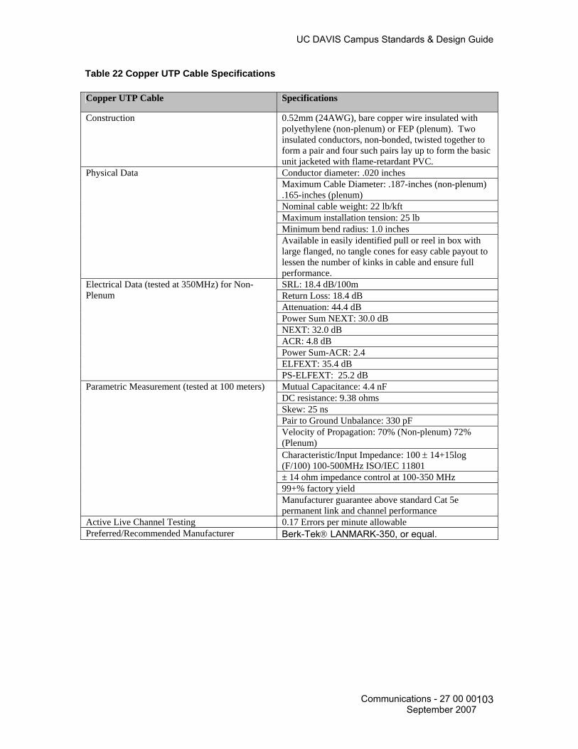
UC DAVIS Campus Standards & Design Guide
Table 22 Copper UTP Cable Specifications Copper UTP Cable Specifications
Construction 0.52mm (24AWG), bare copper wire insulated with polyethylene (non-plenum) or FEP (plenum). Two insulated conductors, non-bonded, twisted together to form a pair and four such pairs lay up to form the basic unit jacketed with flame-retardant PVC. Conductor diameter: .020 inches Maximum Cable Diameter: .187-inches (non-plenum) .165-inches (plenum) Nominal cable weight: 22 lb/kft Maximum installation tension: 25 lb Minimum bend radius: 1.0 inches
Physical Data
Available in easily identified pull or reel in box with large flanged, no tangle cones for easy cable payout to lessen the number of kinks in cable and ensure full performance. SRL: 18.4 dB/100m Return Loss: 18.4 dB Attenuation: 44.4 dB Power Sum NEXT: 30.0 dB NEXT: 32.0 dB ACR: 4.8 dB Power Sum-ACR: 2.4 ELFEXT: 35.4 dB
Electrical Data (tested at 350MHz) for Non-Plenum
PS-ELFEXT: 25.2 dB Mutual Capacitance: 4.4 nF DC resistance: 9.38 ohms Skew: 25 ns Pair to Ground Unbalance: 330 pF Velocity of Propagation: 70% (Non-plenum) 72% (Plenum) Characteristic/Input Impedance: 100 ± 14+15log (F/100) 100-500MHz ISO/IEC 11801 ± 14 ohm impedance control at 100-350 MHz 99+% factory yield
Parametric Measurement (tested at 100 meters)
Manufacturer guarantee above standard Cat 5e permanent link and channel performance
Active Live Channel Testing 0.17 Errors per minute allowable Preferred/Recommended Manufacturer Berk-Tek® LANMARK-350, or equal.
Communications - 27 00 00 September 2007
103
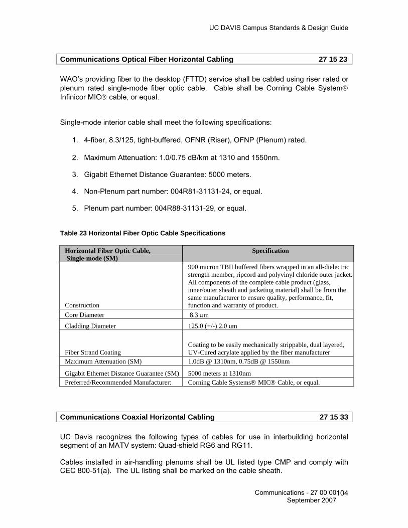
UC DAVIS Campus Standards & Design Guide
Communications Optical Fiber Horizontal Cabling 27 15 23
WAO’s providing fiber to the desktop (FTTD) service shall be cabled using riser rated or plenum rated single-mode fiber optic cable. Cable shall be Corning Cable System® Infinicor MIC® cable, or equal. Single-mode interior cable shall meet the following specifications:
1. 4-fiber, 8.3/125, tight-buffered, OFNR (Riser), OFNP (Plenum) rated.
2. Maximum Attenuation: 1.0/0.75 dB/km at 1310 and 1550nm.
3. Gigabit Ethernet Distance Guarantee: 5000 meters.
4. Non-Plenum part number: 004R81-31131-24, or equal.
5. Plenum part number: 004R88-31131-29, or equal.
Table 23 Horizontal Fiber Optic Cable Specifications
Horizontal Fiber Optic Cable, Single-mode (SM)
Specification
Construction
900 micron TBII buffered fibers wrapped in an all-dielectric strength member, ripcord and polyvinyl chloride outer jacket. All components of the complete cable product (glass, inner/outer sheath and jacketing material) shall be from the same manufacturer to ensure quality, performance, fit, function and warranty of product.
Core Diameter 8.3 μm
Cladding Diameter 125.0 (+/-) 2.0 um
Fiber Strand Coating Coating to be easily mechanically strippable, dual layered, UV-Cured acrylate applied by the fiber manufacturer
Maximum Attenuation (SM) 1.0dB @ 1310nm, 0.75dB @ 1550nm
Gigabit Ethernet Distance Guarantee (SM) 5000 meters at 1310nm Preferred/Recommended Manufacturer: Corning Cable Systems® MIC® Cable, or equal.
Communications Coaxial Horizontal Cabling 27 15 33 UC Davis recognizes the following types of cables for use in interbuilding horizontal segment of an MATV system: Quad-shield RG6 and RG11. Cables installed in air-handling plenums shall be UL listed type CMP and comply with CEC 800-51(a). The UL listing shall be marked on the cable sheath.
Communications - 27 00 00 September 2007
104

UC DAVIS Campus Standards & Design Guide
Coaxial cables installed in buildings must meet the same code requirements as telecommunications cables. All conductive cabling and associated components shall comply with Article 800 of the CEC. Reference Division 27 43 00 Master Antennae Television (MATV) System for more information.
Communications Faceplates and Connectors 27 15 43 The Network Access Module (NAM) is the actual connector or jack installed in a faceplate or surface mounted box upon which the UTP, coax and fiber optic cable is terminated on in the work area. The term Work Area Outlet (WAO) refers to the actual faceplate or surface mounted box installed in the work area. Work Area Outlet (WAO) Faceplates, Surface Mount Boxes, Wiremold® Adapter and Modules
Faceplates, Surface Mount Interface Boxes and 106-Type Receptacles:
1. WAO’s shall be installed using fog white, flush-mounted, front entry, front removable, individual port faceplates and surface mount interface boxes. Faceplate color is recommend to match the décor of the room area and electrical and switch plates where required. Faceplates shall be Ortronics® TracJack®, or equal.
2. WAO’s providing multiple voice, data, video and fiber to the desktop (FTTD)
service shall be installed using the faceplates listed in Table 24. All voice and data (to include FTTD) faceplates shall be a minimum of 4-port. Blank modules of the same color and manufacturer as the faceplate or surface mounted box shall cover all open ports not utilized by a NAM.
3. 106-Type Receptacles, as listed in Table 24, shall be used when installing NAM’s
in metallic type surface raceways using standard electrical duplex receptacle type faceplates.
4. Modular furniture adapters, bezels and brackets shall be used when installing
NAM modules on modular furniture and Wiremold® raceway products. Adapters, bezels and brackets shall meet the manufacturer’s specific requirements for their product to ensure fit, function and appearance. The color of the adapters, bezels and brackets shall match the particular furniture or Wiremold® item. Reference Table 25 for a list of Wiremold® and Ortronics® products for raceway installations. Adapters, bezels and brackets shall be Ortronics® TracJack®, or equal.
5. Angled faceplates are preferred in the Dorm Rooms.
Communications - 27 00 00 September 2007
105

UC DAVIS Campus Standards & Design Guide
Table 24 WAO Faceplates and Surface Mount Boxes
Wiremold® Part Number, or equal
Description
CM-SAP CM Series Single Gang Angled Faceplate, Ivory CM2-U2TJ CM2 Module for TracJack, Ivory
Ortronics® Part Number, or equal.
Description
OR-40300546 Single Gang, Holds 4 TracJack®, Fog White, Front Entry/Removable OR-40300545 Single Gang, Holds 6 TracJack®, Fog White, Front Entry/Removable OR-40300555 Dual Gang, Holds 6 TracJack®, Fog White, Front Entry/Removable OR-40300554 Dual Gang, Holds 8 TracJack®, Fog White, Front Entry/Removable OR-40300185 Surface Mount Box, Single Gang, Fog White, Front Entry/Removable OR-40400054 Surface Mount Box, 2-Port, TracJack®, Fog White, Front Entry/Removable OR-40400072 Surface Mount Box, 4-Port, TracJack®, Fog White, Front Entry/Removable OR-40800017 106-Type Receptacles, 2-Port, TracJack®, Fog White, Front Entry/Removable OR-40800019 106-Type Receptacles, 4-Port, TracJack®, Fog White, Front Entry/Removable OR-854045212 Single Gang, Holds 1 TracJack® for Wall-Mounted Telephone, Stainless Steel Modules shall be manufactured by an ISO 9001 certified manufacturer and be fully compliant with ISO/IEC/DIS-11801 standard and meet FCC specifications where applicable. These products shall be UL® certified where applicable Table provides a summary of approved modules. Blank modules shall be installed in all vacant faceplate and surface mounted box ports. Blank color shall match the color of the faceplate or box and shall be from the same manufacturer as the faceplate to ensure fit, function and appearance. Table 25 Wiremold® and Ortronics® Raceway Products
Wiremold® Part Number, or equal
Description
ALA-LPB3S2 Low Profile Bezel Cover Plate Ortronics® Part Number, or equal
Description
OR-40300656* Series II Angled Bezel for TracJack® Modules, Fog White, Front Entry/Removable
OR-40300023* Series II Blank Module, Fog White, Front Entry/Removable *Actual color to match Wiremold Raceway and Low Profile Bezel Cover Plate as available from manufacturer
Termination Hardware Requirements at the NAM WAO Each UTP cable shall be terminated at the WAO with a Category 5e, 8P8C, T568A, 180°-degree exit, front installable and front re-moveable modules.
Communications - 27 00 00 September 2007
106

UC DAVIS Campus Standards & Design Guide
1. Ortronics Clarity5E TracJack, OR-TJ5E00, Fog White for Voice NAMs, or equal.
2. Ortronics Clarity5E TracJack, OR-TJ5E00-23, Light Orange for Data NAMs, or equal.
3. Ortronics Clarity5E TracJack, OR-TJ5E00-45, Green for Internal/Local Network
NAMs, or equal.
Termination Hardware Requirements at the Fiber WAO Each fiber optic cable shall be terminated at the WAO using a Small Form Factor LC style connector mounted in an LC type faceplate module. All strands shall be terminated at the WAO and IDF location for testing and verification purposes. Reference Table 25 & 26 for module specifications. The LC connector module shall be from the same manufacturer as the flush mount faceplate to ensure fit, function and appearance and the LC fiber optic connector shall be from the same manufacturer as the fiber optic cable to ensure campus wide network system compatibility, performance and warranty. LC-type module shall be Ortronics® TracJack®, or equal. Termination hardware requirements at the MATV WAO Each coax cable shall be terminated at the MATV WAO with an F-type connector, 180-degree exit, 75-ohm module. The F-type connector module shall match the color and appearance of the faceplate or patch panel to be installed. Reference Table 30 for recommended part number and minimum performance specifications. If the consultant or contractor requests substitutions to the listed products, then documented and demonstrated equivalency of the substituted product shall be provided to CR for their review. Ortronics® TracJack™ is the preferred and recommended manufacturer, or equal. The F-type connector module shall be inserted in a single port, fog white single gang faceplate. Faceplates shall be from the same manufacturer as the F type connector module to ensure proper fit, function and appearance. The module shall be in a standard Fog White color or shall match the existing décor of the room, to include metal type faceplates. Reference Table 24, 26 and 30 for recommended part numbers and minimum performance specifications. If the consultant or contractor requests substitutions to the listed products, then documented and demonstrated equivalency of the substituted product shall be provided to CR for their review. Ortronics® TracJack™ is the preferred and recommended manufacturer, or equal. A 4-11/16 inch × 4-11/16 inch × 2 1/8-inch electrical back box with a single gang plaster ring shall be used at each MATV WAO location. A minimum 1-inch EMT conduit shall be installed to the cable pathway support system. Conduit shall be sized appropriately for the fill rate of cable it is to accommodate. Reference Division 27 05 28.33 for additional information. Install 75Ohm terminator resistors at all unused system terminal points.
Communications - 27 00 00 September 2007
107

UC DAVIS Campus Standards & Design Guide
Table 26 Copper and Fiber NAM Modules
Ortronics® Part Number, or equal.
Description
OR-TJ5E00-23 TracJack®, RJ-45 Module, 8P8C, T568A/B, 180° degree exit, Orange for Data, Front Entry/Removable
OR-TJ5E00-45 TracJack®, RJ-45 Module, 8P8C, T568A/B, 180° degree exit, Green for Internal/Local Network, Front Entry/Removable
OR-TJ5E00 TracJack® RJ-45 Module, 8P8C, T568A/B, 180° degree exit, Fog White for Voice, Front Entry/Removable
OR-42100002 TracJack® Blank Module, Fog White, Front Entry/Removable
OR-63700031 TracJack® LC Single-mode, Angled, 45° degree exit, 2 fibers, feed through, Blue, Front Entry/Removable
OR-63700006 TracJack® F-Connector, 180° degree exit, 75 Ohm, Front Entry/Removable
Communications Connecting Cords, Devices and Adapters 27 16 00
Communications Patch Cords, Station Cords and Cross Connect Wire 27 16 19 Patch cords shall be from the same manufacturer as the termination hardware and cable (patch panels and LC type connectors) to ensure proper compatibility, fit, function, appearance and the highest campus wide system performance levels and warranty. If substitutions are requested by the consultant/contractor, then documented and demonstrated equivalency shall be provided to CR for review and acceptance. Patch cords are designed to work best with components from the same manufacturer and from manufacturers who design their products to work with that specific patch cord. Field fabricated patch cords shall not be used. Patch cords shall be manufactured by a TL 9000 and ISO 9001 Certified Manufacturer and be fully compliant with ISO/IEC/DIS-11801 standard and meet FCC specifications where applicable. These products shall also be UL® certified, where applicable. Performance testing of patch cords shall be conducted at the component level by a UL certified testing laboratory to ensure performance, compatibility, fit, function, appearance and warranty. Performance testing shall include active live channel testing to ensure manufacturer and performance quality. Patch cords shall be of the same or higher transmission category as the cable system installed. Manufactured patch cords shall be installed to meet the minimum bending radius of 0.25 inches as specified in ANSI/TIA/EIA 568-B.1-AD-1, Sub clause Addendum 10.2.1.3
Communications - 27 00 00 September 2007
108

UC DAVIS Campus Standards & Design Guide
Data Patch Cords Preferred and Recommended manufacture is Ortronics Clarity5E Enhanced Category 5E UTP; color Blue for Data NAMs and Green for Internal/Local Connections. Table 27 lists the preferred and recommended manufacturer of patch cord providing data service to WAO’s. Table 27 Manufactured Data Patch Cords Lengths/Specifications
Manufactured Patch Cords Maximum
Length/Performance Ortronics® Part Numbers, Blue
Ortronics® Part Numbers, Green
From the patch panel to the electronic equipment located within the equipment rack, cabinet or backboard
3, 5, 7 foot lengths only
OR-MC5E03-06 (3 ft) OR-MC5E05-06 (5 ft) OR-MC5E07-06 (7 ft)
OR-MC5E03-05 (3 ft) OR-MC5E05-05 (5 ft) OR-MC5E07-05 (7 ft)
From the WAO to the computer workstation 7, 9, 15 foot lengths only
OR-MC5E07-06 (7 ft) OR-MC5E09-06 (9 ft) OR-MC5E15-06 (15 ft)
OR-MC5E07-05 (7 ft) OR-MC5E09-05 (9 ft) OR-MC5E15-05 (15 ft)
Pair to Pair NEXT Loss @ 100MHz 37.2 to 38.1 dB
Return Loss @ 100MHz 18 dB
Active Live Channel Testing 0.17 error per minute allowable
Preferred/Recommended Manufacturer, or equal. Ortronics® Clarity5E
Voice Cross-Connect Wire Proper selection and installation of cross-connect jumper wire used between cross-connect blocks is essential to the overall performance of the network. The twist shall be maintained to within 0.5 inches of the entry into the cross-connect block. Contractors shall complete the horizontal and riser cross-connections at the IDF location(s). Contractor shall provide sufficient jumper wire (white/blue, 24AWG for voice, white/red, 24AWG for Fire Systems) to complete all identified cross-connects at the IDF locations. Note: Provide a comment in the specifications requiring the contractor to contact Communications Resources to provide the contractor a NAM x-connect assignment spreadsheet.
Fiber to the Desktop (FTTD) Patch Cords Table 28 lists the preferred and recommended manufacturer of duplex patch cords providing FTTD service to WAO’s.
Communications - 27 00 00 September 2007
109

UC DAVIS Campus Standards & Design Guide
Table 28 Manufactured FTTD Patch Cords Lengths/Specifications
Manufactured Patch Cords Maximum Length/Performance
Corning Cable System© Part Numbers for
Single-mode Cords
From the patch panel to the electronic equipment located within the equipment rack, cabinet or backboard
3, 5, 7 foot lengths only 040402R5120003F (3 feet) 040402R5120005F (5 feet) 040402R5120007F (7 feet)
From the WAO to the computer workstation 7, 9, 15 foot lengths only
040402R5120007F (7 feet) 040402R5120009F (9 feet) 040402R5120015F (15 feet)
Attenuation (dB/km) 1.0/.75 Bandwidth (MHz/km) N/A Preferred/Recommended Manufacturer, or equal.
Corning Cable Systems®
Fiber Optic Patch Cords Fiber optic patch cords shall be of the manufacturer duplex type and from the same manufacturer as the termination hardware and cable to ensure compatibility, fit, function, appearance and performance. Field fabricated patch cords shall not be used. Proper bend radius shall be maintained at the termination and WAO locations. Ultra PC 568SC duplex type connector patch cords shall be used at the outside plant and riser cable termination locations. Labeling Patch cords shall be properly labeled in accordance with UC Davis and TIA/EIA 606-A standards. Note: Generally all patch cords are provided and installed by the university, excluding voice x-connects at the IDF locations. Please contact Communications Resources to determine the need to specify patch cords when designing a project.
Communications - 27 00 00 September 2007
110

UC DAVIS Campus Standards & Design Guide
Data Communications 27 20 00 Data Communications Wireless Access Points 27 21 33 This chapter establishes the specifications, type, testing and acceptance of a wireless network system. Wireless Access Coverage Adequate provision of wireless NAMs shall be specified in new and remodeled construction projects to provide coverage throughout the area under construction. Wireless Access NAM Wireless access NAM consists of a single data Network Access Module (NAM). The wireless NAM is to be terminated with an 8-position, 8 conductor module and placed into a 2 port surface mount box. Location of the wireless NAM is based on the room design:
1. Standard ceiling height rooms (offices, classrooms, conference rooms, etc.) with drop tile ceiling: leave the NAM concealed above the drop tile ceiling with 10 feet of slack. Place the NAM where it will provide the greatest amount of useable coverage.
2. High ceiling rooms (lecture rooms, auditoriums, etc): dependant on the size of
the room provision for two NAM locations on each side wall at approximately 8’-6” AFF. Install each NAM location with a 4-11/16” square back box flush in the wall with a one port faceplate.
3. Hard cap ceilings: Install the NAM with a 4-11/16” square back box and one port
faceplate on the wall at approximately 8’-6” AFF. Wireless network equipment is university provided and installed. At the time of this of publication, the Engineering and Construction Management office, Communications Resources, is evaluating current and emerging wireless standards, as well as, the different manufacturer’s wireless products. This chapter will be updated in future revisions as this new system progresses.
Communications - 27 00 00 September 2007
111
UC DAVIS Campus Standards & Design Guide
VOICE COMMUNICATIONS 27 30 00 All campus approved wall phones (with an ADA compliant handset); emergency call boxes and towers shall be installed in accordance with ADA requirements. Installed wall, counter-top and weatherproof telephones, in addition to emergency call boxes and WAO’s, shall meet the requirements of the Americans with Disabilities Act (ADA). This requirement is referenced in ANSI/TIA/EIA 568-B.1. http://www.access-board.gov
Voice Communications Telephone Sets, Facsimiles and Modems 27 32 00
Courtesy, Pay, Text, Emergency and Wheel Chair Elevator Telephones In order to comply with the American Disabilities Act (ADA) Accessibility Guidelines: A. The mounting height of the device box for Wall Mounted Telephones shall be 40-inches Above the Finished Floor (AFF). Wall-mounted telephones shall not be installed above a counter top. B. The mounting height of the device box for a wheelchair accessible telephone (to include payphones and wheel chair elevator phones) shall be 40-inches AFF. C. If a Text Telephone is required, it shall not be mounted to the wheelchair accessible telephone position. The text telephone unit shall require a power receptacle at 18” AFF under the Text Telephone. D. If a wheelchair elevator is planned, a WAO shall be installed as close as possible to its location for the installation of an emergency phone. Note: Wall telephones shall not be installed above or over Laboratory countertops. A standard desktop telephone may be installed in these unique locations.
Telephones Sets 27 32 13 Indoor Wall-Mounted Single-Line Wall Telephone Features: • Fully Modular • 9' Handset Cord • Single-Gong Ringer • Ringer Volume Control
Communications - 27 00 00 September 2007
112
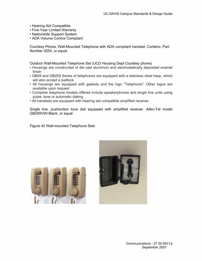
UC DAVIS Campus Standards & Design Guide
• Hearing Aid Compatible • Five-Year Limited Warranty • Nationwide Support System • ADA Volume Control Compliant Courtesy Phone, Wall-Mounted Telephone with ADA compliant handset, Cortelco, Part Number 2554, or equal. Outdoor Wall-Mounted Telephone Set (UCD Housing Dept Courtesy phone) • Housings are constructed of die cast aluminum and electrostatically deposited enamel finish • GB59 and GB259 Series of telephones are equipped with a stainless steel hasp, which will also accept a padlock • All housings are equipped with gaskets and the logo “Telephone". Other logos are available upon request • Complete telephone models offered include speakerphones and single line units using pulse, tone or automatic dialing • All handsets are equipped with hearing aid compatible amplified receiver Single line, pushbutton tone dial equipped with amplified receiver. Allen-Tel model GB259V00 Black, or equal. Figure 42 Wall-mounted Telephone Sets
Communications - 27 00 00 September 2007
113

UC DAVIS Campus Standards & Design Guide
Elevator Telephones 27 32 23
Ring-Down Emergency Telephones 27 32 26 Vandal-resistant Emergency/Information systems provide exceptional clarity, performance and a sense of security. Often used in college campuses, parking facilities, shopping malls, medical centers and industrial campuses. Lighting Atop the Wall Mount, enclosed in a clear polycarbonate security enclosure shall be a combination blue light and strobe. The blue light shall be a 7 watt high efficiency, compact fluorescent light with a 10,000 hour lifetime. It shall be lit at all times. The strobe shall provide 1.5 million candlepower and flash 70 times per minute when the emergency phone is activated and continue flashing until the call has been completed. The polycarbonate refractor/housing shall have a prismatic pattern to increase visibility at greater distances. The Wall Mount shall have a concealed 7 watt high efficiency, long life compact fluorescent light illuminating the emergency phone face plate at all times. Electrical The communication device shall require no external power. It shall be powered by the phone line, PBX extension, or a wireless communication interface. Standard 120VAC power shall be required for the blue light/strobe and face plate light. Wall Mount shall be 24VDC powered. All lamps and fixtures shall be UL and C.S.A. listed. All electrical components shall be hard wired and concealed within the tower. All wiring and electrical fixtures comply with the standards of the National Electrical Code, UL and C.S.A. Mounting Wall Mount shall be designed to mount on the surface of a wall.
Communications - 27 00 00 September 2007
114

UC DAVIS Campus Standards & Design Guide
Options Power Wall Mount shall be available in a 24VDC version. Blue light/strobe shall include ultra-bright, long-lasting LEDs instead of compact fluorescent. Face plate light shall be 24VDC LED bulb. Communications Wall Mount shall accept any 400-Series flush mounting emergency phone. Compliance CSA Certified to UL Standard 60950 Warranty Equipment shall be warrantied against any defects in material and workmanship, under normal use, for a period of one year from date of installation. In the event system is found by manufacturer to be defective within the warranty period, manufacturer shall repair and/or replace any defective parts, provided the equipment is returned to manufacturer. Emergency/Information Tower General Description The unit shall be a highly vandal-resistant free-standing steel emergency phone tower mount, model ETP-MT/R, no substitutions, with built-in combination blue light/strobe and lighted faceplate. The tower shall house an ADA-compliant line-powered communication device manufactured by Talk-A-Phone Co. Externally-powered devices are not acceptable. Construction The unit shall be constructed of 0.25" thick steel and weigh approximately 400 lbs. The unit shall measure 10" W x 12" D x 118" H with a 2" radius on each corner. A multi-coat, rust-inhibitive coating shall be applied to withstand prolonged exposure to harsh environments. An internal base plate shall be fully welded within the tower 2" above the tower base. The base plate shall be fabricated of 0.75" A-36 steel. There shall be a 4" diameter center hole for wiring access and four 1" diameter holes for anchor bolt clearance. Tower shall have a wiring access opening measuring 11" H x 8" W, located 15" above the base of the tower. The opening shall have a flush cover plate with a wall thickness of 0.25", held in place by two 10-24 countersunk, tamper-resistant spanner screws.
Communications - 27 00 00 September 2007
115

UC DAVIS Campus Standards & Design Guide
An opening shall be cut in the face of the column for mounting any flush-mounting, 400-Series emergency phone models. The lower edge of the opening shall slope down 30º from rear to front, making the edge difficult to use as a shelf yet convenient as a writing surface. The word "EMERGENCY" shall be emblazoned on all four sides in 3.25" high reflective white letters (custom lettering, sizes and colors available). Mounting The tower shall include 24 inch J-bolts for mounting into a 24" x 24" concrete foundation, depth to vary according to local regulations and other site-specific considerations. J-bolts shall protrude approximately 5 inches from surface of foundation. Manufacturer shall be Talk-A-Phone Model ETP-MT/R Emergency Phone Tower Mount, Clear Sky Blue color, or equal. Emergency/Information Phone Wall Mount General Description The unit shall be a highly visible, vandal-resistant wall-mounted stainless steel emergency phone station, model ETP-WM, no substitutions, with built-in combination blue light/strobe and lighted faceplate. The Wall Mount shall house an ADA-compliant, line-powered communication device manufactured by Talk-A-Phone Co. Externally-powered devices are not acceptable. Generally specified in UCD parking structures. Construction The unit shall be constructed of 11 gauge #4 vertical brushed stainless steel and weigh approximately 43 lbs. It shall be designed to withstand prolonged exposure to harsh environments. The unit shall measure 10.25" W x 8" D x 31.75" H with 1.5" radius front corners. Blue light/strobe shall be housed in a vandal resistant, blue polycarbonate refractor housing. Refractor housing shall further be enclosed in a clear polycarbonate impact-resistant enclosure. An opening in the Wall Mount shall allow for a 400-Series Emergency Phone to be flush mounted into the Wall Mount and recessed by approximately 1.5". The word "EMERGENCY" shall be emblazoned on both sides in reflective red letters (custom lettering, sizes and colors available). Manufacturer shall be Talk-A-Phone Model ETP-WM Emergency Phone Wall Mount, Clear Sky Blue color, or equal.
Communications - 27 00 00 September 2007
116
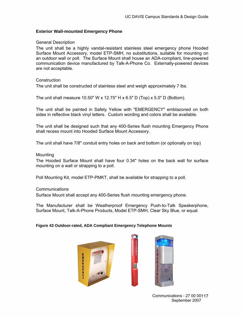
UC DAVIS Campus Standards & Design Guide
Exterior Wall-mounted Emergency Phone General Description The unit shall be a highly vandal-resistant stainless steel emergency phone Hooded Surface Mount Accessory, model ETP-SMH, no substitutions, suitable for mounting on an outdoor wall or poll. The Surface Mount shall house an ADA-compliant, line-powered communication device manufactured by Talk-A-Phone Co. Externally-powered devices are not acceptable. Construction The unit shall be constructed of stainless steel and weigh approximately 7 lbs. The unit shall measure 10.50" W x 12.75" H x 6.5" D (Top) x 5.0" D (Bottom). The unit shall be painted in Safety Yellow with "EMERGENCY" emblazoned on both sides in reflective black vinyl letters. Custom wording and colors shall be available. The unit shall be designed such that any 400-Series flush mounting Emergency Phone shall recess mount into Hooded Surface Mount Accessory. The unit shall have 7/8" conduit entry holes on back and bottom (or optionally on top) Mounting The Hooded Surface Mount shall have four 0.34" holes on the back wall for surface mounting on a wall or strapping to a poll. Poll Mounting Kit, model ETP-PMKT, shall be available for strapping to a poll. Communications Surface Mount shall accept any 400-Series flush mounting emergency phone. The Manufacturer shall be Weatherproof Emergency Push-to-Talk Speakerphone, Surface Mount, Talk-A-Phone Products, Model ETP-SMH, Clear Sky Blue, or equal. Figure 43 Outdoor-rated, ADA Compliant Emergency Telephone Mounts
Communications - 27 00 00 September 2007
117

UC DAVIS Campus Standards & Design Guide
Emergency Phones General Description The Emergency Phone shall consist of an outdoor-rated, vandal resistant and ADA-compliant hands-free speakerphone communications device with a stainless steel faceplate and metal buttons. Manufacturer The Manufacturer shall be Talk-A-Phone Co. (773) 539-1100, 5013 N. Kedzie, Chicago, Illinois 60625, www.talkaphone.com. THERE ARE NO EQUIVALENTS. Options Single Emergency button model ETP-400D: The Emergency Phone shall be Talk-A-Phone model ETP-400, or equal and have one red anodized aluminum tactile button labeled "EMERGENCY" and one 0.375" diameter red light emitting diode (LED) labeled "LIGHT ON INDICATES CALL RECEIVED". The unit shall be programmable from a remote location and have a two number dialing capability, reverting to the second number if the first is busy or does not respond. The unit shall be totally hands-free on both sides after connection is initiated at site or by attendant. The unit shall be phone line powered, requiring no outside power source or battery back-up. DIP switch programming, push to talk devices, and devices requiring external power are not acceptable. The unit shall have a dedicated communication line. Second button Emergency/Info model ETP-400D: The Emergency Phone shall be Talk-A-Phone model ETP-400D, or equal and have one red anodized aluminum tactile button labeled "EMERGENCY", one black anodized aluminum tactile button labeled "INFO" and one 0.375" diameter red light emitting diode (LED) labeled "LIGHT ON INDICATES CALL RECEIVED". The unit shall be programmable from a remote location and have a two number dialing capability per button, reverting to the second number if the first is busy or does not respond. The unit shall be totally hands-free on both sides after connection is initiated at site or by attendant. The unit shall be phone line powered, requiring no outside power source or battery back-up. DIP switch programming, push to talk devices, and devices requiring external power are not acceptable. The unit shall have a dedicated communication line. Keypad model ETP-400K: The Emergency Phone shall be Talk-A-Phone model ETP-400D, no substitutions, and have one red anodized aluminum tactile button labeled "EMERGENCY", one black anodized aluminum tactile button labeled "INFO" and one 0.375" diameter red light emitting diode (LED) labeled "LIGHT ON INDICATES CALL RECEIVED". The unit shall be programmable from a remote location and have a two number dialing capability per button, reverting to the second number if the first is busy or does not respond. The unit shall be totally hands-free on both sides after connection is initiated at site or by attendant. The unit shall be phone line powered, requiring no outside power source or battery back-up. DIP switch programming, push to talk devices, and devices requiring external power are not acceptable. The unit shall have a dedicated communication line.
Communications - 27 00 00 September 2007
118

UC DAVIS Campus Standards & Design Guide
Keypad but no EMERGENCY button model ETP-400KS: The Emergency Phone shall be Talk-A-Phone model ETP-400KS, or equal and have one black anodized aluminum tactile button labeled "CALL", an all metal 12-button keypad and one 0.375" diameter red light emitting diode (LED) labeled "LIGHT ON INDICATES CALL RECEIVED". Using the keypad, the unit shall be capable of dialing any number authorized by the telephone line. The unit shall be totally hands-free on both sides after connection is initiated at site or by attendant. The unit shall be phone line powered, requiring no outside power source or battery back-up. DIP switch programming, push to talk devices, and devices requiring external power are not acceptable. The unit shall have a dedicated communication line. Figure 44 Outdoor-rated, ADA-Compliant Hands-free Emergency Phones
TTY Equipment 27 32 36 TTY Payphone Provision for a 110 outlet about 18 inches from the floor. The phone jack to be installed at 40 inches from the floor
Figure 45 ADA Compliant TTY/TDD Payphone
Communications - 27 00 00 September 2007
119

UC DAVIS Campus Standards & Design Guide
AUDIO-VISUAL SYSTEMS 27 40 00 The Design Process. UC Davis Audio-Visual (A/V) systems designed and installed in new campus facilities shall consist of one or more the following three basic elements: • Sound System – A complete sound system meeting the performance standards
specified below to be complimented with an ADA approved assisted listening system.
• Video System – A complete video system consists of various display devices consistent with the intended use of the room and viewable from at least 80% of the room while meeting performance standards listed below.
• Remote Control Systems – A microprocessor controlled audio-visual system provides for the remote control of the various media systems installed in a room. These systems shall follow the standards established by the Classroom committee’s selection of the Smart Panel or equal, which enables a complete room display without extensive operations training.
The design of an A/V system shall be based upon customer requirements, as well as, the intended room function. The electronic equipment and cabling shall be consistent with industry standards. A Communications Resources representative shall have final approval of all A/V systems. All A/V systems designed and installed shall meet the most current Americans with Disabilities Act (ADA) requirements, including assisted listening systems, visual access and accommodations. The design consultant shall ensure all requirements are addressed. Performance Standards All A/V systems shall meet, as a minimum, the following performance standards unless restricted by the published specifications of a specific piece of manufacturer’s equipment. Audio Signal: • Signal-to-Noise Ratio (including cross talk): 55 dB minimum. • Total Harmonic Distortion: 0.1% maximum from 20 Hz to 20,000 Hz. • Frequency Response: +/= -1.0 dB, 20 Hz to 20,000 Hz. Audio Reproduction: • Signal–to–Noise Ratio (including cross talk): 55 dB minimum. • Total Harmonic Distortion: 1% maximum from 30 Hz to 15,000 Hz.
Communications - 27 00 00 September 2007
120

UC DAVIS Campus Standards & Design Guide
• Sound Output Capability: Provide program levels of not less than 95 dB in the seating area without objectionable distortion, rattle or buzz. Several different samples, such as recorded music and microphones, shall be employed as test signals.
• Hum and Noise: Hum and noise shall be inaudible (below the background noise level of the space) under normal operation and as observed in normal seat locations.
Video Signal: • Signal-to-noise Ratio (peak to RMS) un-weighted DC to 4.2 MHz: 55 dB minimum. • Cross talk: Cross talk (un-weighted DC to 4.2 MHz): 45 dB minimum. • Frequency Response: +/= 0.5 dB to 4.2 MHz. • Line and Field Tilt: 2% minimum. • Differential Gain: 3% maximum. • Differential Phase: 2º-degree maximum. Video Timing: • System Timing: Synchronize coincidence within 50 nanoseconds. • Color Timing: Within 2º-degrees at 3.58 MHz. Optical: • The light fall-off from the center of the projected image to all four corners, as
measured at the projected image plane, shall not exceed 50% for video projector images and 35% from slide projector images.
• Fixed projectors, lenses and cameras shall be solidly mounted and braced so there shall be no observable movement in the image induced by motor vibration or other mechanical operations.
Control System: • Correct functional operation for all specified controls. • Feedback of the active function at operator and wired remote stations. • Wireless systems neither shall be the source of, nor be affected by, radio-frequency
interference to and from any external signal devices.
Integrated Audio-Video Systems and Equipment 27 41 16 MULTIMEDIA CLASSROOMS AND OTHER LEARNING SPACES STANDARDS The preferred method for A/V installation is a wall mounted media cabinet with all cabling and conduit being routed thru walls and ceilings.
Communications - 27 00 00 September 2007
121
UC DAVIS Campus Standards & Design Guide
Lighting
Classrooms require lighting that can produce enough brightness for note taking and reading while at the same time is controlled to allow audio-visual projection without washing out the images on a screen or TV monitor. Above all, the lighting controls should be simple to use, totally manually operated, and all pre-set controls eliminated.
Lighting fixtures and lamps: • Provide minimum light intrusion onto projection screens (less than 2 foot candles at
the screen). • Provide 20-35 foot candles of task lighting at student seats. • Provide 20-35 foot candles of light for chalkboard or white board illumination. • Provide energy efficiency, low heat generation, and easy maintenance. • Light fixtures should be fluorescent and include 3”, 1.5”, and .5”, semi-specular
parabolic louvers to minimize audience glare and light spillage on projection screens. • Fluorescent tubes should be 35 degree Kelvin for natural color. • Ballasts should not operate at frequencies greater than 30 KHz in order to eliminate
potential interference with infrared controls. General guidelines for the selection of light fixtures should include: 1. The use of recessed lamps in sharp cutoff luminaries to provide controlled lighting
with minimal light spill on projection screens and to avoid shining light directly in the audience’s view.
2. No incandescent lamps installed in order to reduce maintenance, conserve energy, and reduce heat generation.
3. Carefully planning any use of pendant lighting fixtures to ensure that ambient light at the screen remains within specifications and the fixtures do not invade the light path of projected images or viewer sight lines.
There should be a minimum of 3 lighting zones in each classroom: • Front presentation/blackboard and front seating area. • Center seating area. • Rear seating area. • Lights at the front of the room should illuminate the chalkboard areas to improve
readability. • Large lecture halls will have a 4th light zone of just the board area separate from the
front presentation area. Lighting controls 1. Each zone will have a simple on/off switch with a corresponding slider type control
for dimming each zone to desired levels.
Communications - 27 00 00 September 2007
122

UC DAVIS Campus Standards & Design Guide
2. When the front lights are turned off for screen projection, the remaining illuminated light zones should allow no more than 2 foot candles of ambient room light to fall on the screen.
3. Each light switch control should be clearly labeled to indicate which switch controls which lights.
4. Light control switches should be conveniently located at the front of the room and clustered by the media cabinet so the instructor can control lighting levels during the class presentation.
5. An additional light switch should be located at each door entry to the classroom to control one bank of lights to sufficiently illuminate the room upon entry. This would ideally be the blackboard lights or lighting zone 1. These door light switches should be the illuminated type so they can be easily found in a darkened room.
6. Large lecture halls should have 24/7 safety lighting to allow safe entrance into the hall but shall not intrude onto any projection screen surface.
7. Additionally, signs should be located at all switch locations to remind occupants to turn off lights when vacating the room.
Power Requirements One and Two-gang outlet boxes: 4-11/16” square by 3-1/2” deep box with single-gang and double-gang plaster rings respectively. Three-gang and larger: ganged or masonry boxes, minimum 3” deep. Outlet Boxes Locations: 1. Duplex outlet power box will be installed at each ceiling mounted projector location.
Wherever possible it will be flush mounted to the ceiling and within 2 feet of the projector location.
2. Quad outlet power box will be installed inside the A/V Smart Panel at the designated wall location placement of the media cabinet.
3. Power junction box will be located in the ceiling with flex cable to connect to each electric projection screen. Coordination the exact location with the Communication Resources university representative.
4. Quad outlet power box will be installed on the back wall of the room to allow for auxiliary A/V equipment to be installed as needed. The exact location to be designated by the CR university representative.
5. Duplex outlet power box will be installed at each wall Assistive Listening Device location which will be 96” AFF.
Power outlets for the projector power and the media cabinet power will be on the same circuit with a minimum 20 amp load.
Communications - 27 00 00 September 2007
123

UC DAVIS Campus Standards & Design Guide
No floor mounted outlet boxes to be located in the teaching area unless the university and A/V installation representatives indicate they are needed as part of the A/V installation design. Provide common ground for all A/V power outlet boxes. Conduit Requirements The preferred method for A/V installation is a wall mounted media cabinet with all cabling and conduit being routed thru walls and ceilings. Several conduits shall be installed from the A/V Smart Panel located behind the A/V Media Cabinet to: • Projector location – Minimum of 2” conduit. Conduit must run the entire distance to
the projector location. Conduit will not have more than two 90 degree turns within the entire length of the run.
• Wall speaker locations – Minimum of 1” conduit to each wall speaker location. Conduit will not have more than two 90 degree turns within the entire length of the run.
• Ceiling speaker locations – Minimum of 1” conduit. If there is a drop ceiling in the room, the conduit may be stubbed out above the ceiling allowing cabling to be run above the ceiling. If it is a plenum rated ceiling then conduit must run the entire distance to each ceiling speaker location. Conduit will not have more than two 90 degree turns within the entire length of the run.
• Wall mounted assistive listening device locations – Minimum of 1” conduit to each wall location. Conduit will not have more than two 90 degree turns within the entire length of the run.
• Rear wall auxiliary equipment location – Minimum of 1” conduit to rear wall location. Conduit will not have more than two 90 degree turns within the entire length of the run; the exact location to be designated by the CR university representative.
Accessible pull boxes are required so that no conduit pull is longer than 100 feet. Install an insulated bushing on each end of all conduits including conduit stubs. Clearly document the exact location of pull boxes, show exact locations on record drawings and provide documentation to the university’s representative. All conduits shall be clear of all debris and have no obstructions to ensure the full inside dimension is available for wire/cables. Bushings required on all conduits.
Communications - 27 00 00 September 2007
124
UC DAVIS Campus Standards & Design Guide
Pull Wires Pull wire to be provided in all raceways over 4 feet in length. All pull wires installed will have a minimum tensile strength of 200 pounds. Special Back Boxes Smart Panel back box is located flush mounted within the wall where the media cabinet is located. Preferred size is 18” x 18” x 4” deep junction box. The media cabinet power and NAM boxes are located within the smart panel. Wall mounted speaker back boxes shall be standard size to accommodate 1” conduit from the smart panel. Ceiling mounted speakers for drop ceilings shall have model specific plates along with tile rails for support. Assistive Listening Device locations shall have a standard back box to accommodate 1” conduit from the smart panel. Rear wall location for auxiliary equipment shall have a standard back box to accommodate 1” conduit to the smart panel. Floor boxes Floor boxes will not be installed for A/V cabling unless the university representative indicates it is desirable and falls within the installation plans for the room.
Media Cabinet Multimedia electronics, equipment and teacher input are contained within the Media Cabinet. Media cabinet is a 22”W x 30”H x 24”D enclosure. Special heavy duty rotating slide out shelving systems are available when installing audio and video equipment in custom cabinetry, entertainment centers and in walls. Locate media cabinet near light switches and projector screen switch to ease instructor use. Speakers Audio reinforcement in large lecture halls will be via two methods: • Speech presentation will be via ceiling mounted speakers dispersed throughout the
room. The number of speakers required will be determined by the university representative.
• Presentation materials such as video etc will be via front wall mounted speakers. There will be a minimum of two speakers used for this audio reinforcement. Additional speakers will be determined by the university representative. Height for installation points to be determined by size and dimensions of the room and sound dispersal pattern to cover all seating areas.
Communications - 27 00 00 September 2007
125

UC DAVIS Campus Standards & Design Guide
Audio reinforcement in small classrooms will be via one speaker system. Speech presentation and presentation materials will all be routed through the front wall mounted presentation speakers. A minimum of two speakers will be used for this audio reinforcement.
Wall mounted speakers shall be installed on either side of the projection screen minimally at 84” AFF. Projection Screens Screen placement is critical to ensure proper viewing angles for all seats in a room. The following considerations should be applied to the placement of projection screens. • Most instructors prefer to teach from the center of the room.
• Most instructors utilize projected images to augment materials written on the board.
Therefore, it is advantageous to maximize the amount of usable board space that remains available while projection screen is in use.
• Avoid positioning a screen to face uncontrolled light sources such as windows, skylights, exit signs, etc.
Screen placements may therefore be centered in the room, offset to the left or right side of the room or angled in a corner of the room. Exact placement will be determined by the university representative. Locate projection screen switch near Media Cabinet to ease instructor use. Screen Specifications • Projection screens will be electric unless otherwise determined by the university
representative.
• For low ceiling rooms the projector may be recessed in the ceiling to maximize the viewing surface available for image size.
• It is preferred that screens be wall mounted if possible in the context that it allows a large viewable image for the room.
• Screens shall be mounted to clear any installed writing boards when deployed but not to create any obstacle to egress or a gap larger that 3” between screen and the outmost edge of an installed board.
• Electric screens will have a low voltage control box located at the media cabinet location.
• Screen surface must be seamless, solid vinyl with a matte white surface.
• All electric screens regardless of size must be tab tensioned.
Communications - 27 00 00 September 2007
126

UC DAVIS Campus Standards & Design Guide
Projector Mounts Preferred method of mounting is in the ceiling in the classroom utilizing drop ceiling plates when a drop ceiling is present. Drop ceiling plates should contain knock out plates for power and NAM’s to be installed flush to the ceiling. Applicable tile and seismic supports shall be installed for each drop ceiling plate. Rooms not having drop ceilings such as large lecture halls without a projection booth should utilize unistrut with extension poles and appropriate projector mount. Extension poles shall be anchored with cables to ensure no movement of the projector for a steady image and provide seismic support. University representative shall be consulted prior to finalizing any projector mounting systems.
Data NAM’s Data network NAM’s shall be installed in the following locations:
1. Inside the smart panel junction box at the designated wall location placement of the
media cabinet.
2. At each ceiling mounted projector location. Wherever possible it will be located within the drop tile ceiling next to the projector power outlet and within 2 feet of the projector location.
3. On the back wall of the classroom to allow for auxiliary A/V equipment to be installed as needed. The exact location to be designated by the university representative.
Assistive Listening Devices All classrooms or lecture halls having 50 or more fixed seats shall have assistive listening devices (ALD’s) installed to accommodate ADA requirements.
Number of ALD’s installed shall be dependent upon the physical size and dimensions of the classroom to ensure complete coverage of all seats.
Each device shall be installed at 96” AFF within 1 foot of power outlet. Identification Label each conduit at each end with the purpose (e.g. “projector”, “speaker”) and destination (e.g. “media cabinet”, “wall speaker”). Label each outlet box, back box and pull box with purpose. Provide labeling which is clear and permanent, such as black permanent ink marker.
Communications - 27 00 00 September 2007
127

UC DAVIS Campus Standards & Design Guide
MASTER ANTENNA TELEVISION (MATV) SYSTEM 27 43 00 The Design Process. The UC Davis MATV system consists of two distinct systems – Baseband and Broadband (RF). In addition, the campus also supports another RF system for student housing known as the Resident Network or ResNet. The Broadband system (and ResNet) uses modulation and radio frequencies to distribute signals to campus locations. The two systems co-exist and provide connectivity to many of the campus general assignment classrooms and auditoriums. Three basic elements:
• Headend – The building that contains the electronics for receiving and processing TV programs. The UC Davis MATV system provides channel operations with a bandwidth up to 1000 MHz.
• Distribution System – A network of distribution media such as coax cable,
amplifiers, and couplers and splitters. The equipment is normally located in the Building Distribution Frame (BDF) and Intermediate Distribution Frame (IDF). Performance of the broadband distribution system shall meet the forward path bandwidth of 49-1000 MHz (passive components) and a flat gain of no less than 32 dB. Cross modulation, composite triple beat and hum modulation shall be 3 dB or better. Active components shall operate to 1000 MHz.
• Subscriber Drop – The coax cable and MATV Work Area Outlets (WAO) where
the users connect their TV set. In addition to the MATV system, the UC Davis campus employs Moving Picture Experts Group (Mpeg), Video over Internet Protocol (IP) and digital distribution to send sound and images throughout the campus. Some of the standards for these systems are still in development while others are more mature and have accepted industry practices that are observed on campus. In the future, a separate chapter within this standard will be included to expand on those distribution standards that involve these systems as they become more defined and/or deemed as a standard on this campus. The hardware segment consists of the following elements:
• Amplifiers - An amplifier is an electronic device that takes an incoming signal and increases the signal strength so that the signal can transmit a greater distance. An amplifier can be added at any point within a distribution system.
• Coaxial cable - Coaxial cable, commonly called coax, is the most common media
used for distribution of RF signals. A quad-shield type of coax cable is the campus preferred and recommended type.
• Connectors - Connectors are installed on the end of a coaxial cable to provide
electrical and mechanical connection to a system component. The standard connector for use on RG6 and RG11 coax cable is the “F” type connector. The standard connector for semi rigid aluminum coaxial cable is the pin connector.
Communications - 27 00 00 September 2007
128
UC DAVIS Campus Standards & Design Guide
• Modulators - A modulator is an electronic device that modulates baseband video,
audio and data signals to specific carrier frequencies for insertion into the broadband RF distribution system. Modulators are usually located in the Headend.
• Demodulators - A demodulator is an electronic device that removes the
modulation from broadband signals. Demodulators are usually located in the Headend. The output of a demodulator is baseband video and audio.
• Drop Cables - A drop cable is the cable that is connected to a tap at one end and
the back of the MATV WAO at the other end.
• Equalizers - An equalizer is an electronic device with a frequency response that is the opposite of the cable that feeds into it. Equalizers compensate for the non-linear frequency response of the coaxial cable.
• MATV WAO - An MATV WAO outlet is a wall-mounted faceplate with an F-type
Network Access Module (NAM) installed. WAO’s provide the interconnection between the distribution system and the subscribers’ equipment.
The horizontal cable segment consists of the following cable elements:
1. The horizontal cable and connecting hardware that provide the means for transporting the broadband signals between the MATV WAO in the work area and the Intermediate Distribution Frame (IDF).
2. The horizontal cabling pathways and spaces that distribute and support the
horizontal cable and connecting hardware between the MATV WAO and the IDF. This section describes the policies and procedures for the following design activities:
• Determining the type and number of MATV WAO’s in the work area. • Identifying the types and lengths of cable used in the horizontal segment. • Determining termination hardware requirements at the MATV WAO and
BDF/IDF. • Designing the structures needed to support the horizontal cabling. • Determining the broadband distribution equipment required. • Assigning the MATV NAM numbers to the appropriate locations. • Cable testing procedures.
The Type and Number of MATV WAO’s The subscriber drop coax cable shall be terminated at the MATV WAO with a standard F type connector inserted in a standard single gang faceplate.
Communications - 27 00 00 September 2007
129

UC DAVIS Campus Standards & Design Guide
Consultation with the building occupant and Communications Resources is required during the design process to identify the number and location of MATV WAO’s to be installed. Cable Types and Lengths UC Davis recognizes the following types of cables for use in interbuilding horizontal segment of an MATV system: Quad-shield RG6 and RG11. The length of the drop cable shall be no more than 90 m (295 ft). The loss difference between the shortest and longest drop cables from a tap should be no more than 7 dB. This shall provide the recommended signal level at the outlet of 3 dBmv to 10 dBmv. Coaxial cables installed in buildings must meet the same code requirements as telecommunications cables. All conductive cabling and associated components shall comply with Article 800 of the CEC. Cables installed in air-handling plenums shall be UL listed type CMP and comply with CEC 800-51(a). The UL listing shall be marked on the cable sheath. Horizontal coax cables shall be installed in one continuous length and shall not be spliced. Coax cable shall be labeled in the same manner as telecommunications cables. Reference Appendix A Specification 02 for labeling sequence. Reference Table 10-2 for coax cable specifications. Termination hardware requirements at the MATV WAO and BDF/IDF. Each coax cable shall be terminated at the MATV WAO with an F-type connector, 180-degree exit, 75-ohm module. The F-type connector module shall match the color and appearance of the faceplate or patch panel to be installed. Reference Table 10-1 for recommended part number and minimum performance specifications. If the consultant or contractor requests substitutions to the listed products, then documented and demonstrated equivalency of the substituted product shall be provided to CR for their review. Ortronics® TracJack™ is the preferred and recommended manufacturer, or equal. The F-type connector module shall be inserted in a single port, fog white single gang faceplate. Faceplates shall be from the same manufacturer as the F type connector module to ensure proper fit, function and appearance. The module shall be in a standard Fog White color or shall match the existing décor of the room, to include metal type faceplates. Reference Table 10-1 for recommended part number and minimum performance specifications. If the consultant or contractor requests substitutions to the listed products, then documented and demonstrated equivalency of the substituted
Communications - 27 00 00 September 2007
130

UC DAVIS Campus Standards & Design Guide
product shall be provided to CR for their review. Ortronics® TracJack™ is the preferred and recommended manufacturer, or equal. A 4-inch × 4-inch × 2 1/8-inch electrical back box with a single gang plaster ring shall be used at each MATV WAO location. A minimum 1-inch EMT conduit shall be installed to the cable pathway support system. Conduit shall be sized appropriately for the fill rate of cable it is to accommodate. Reference Section 4 for additional information. Each coax cable shall be terminated in the BDF/IDF and connected directly to the wall-mounted signal splitter. If required, the coax cables may also be terminated on a rack or wall-mounted patch panel with a .75 ohm F-type connector, 180-degree exit. A bend limiting strain relief bar shall be used with each patch panel to secure the terminated coax cable. Reference Table 10-1 for recommended part number and minimum performance specifications. If the consultant or contractor requests substitutions to the listed products, then documented and demonstrated equivalency of the substituted product shall be provided to CR for their review. Ortronics® TracJack™ is the preferred and recommended manufacturer, or equal. Cable slack shall be provided at both ends of the cable run to accommodate future cabling system changes. Approximately 6-inches of slack at the WAO location and 6-feet of slack at the equipment end (headend). Install 75Ohm terminator resistors at all unused system terminal points. Maintain consistent absolute signal polarity at all connectors, patch panels and connection points accessible in the system. Video and RF/Broadband connector convention (Signal, Connector, Wire):
• Signal: signal phase, Connector: center pin, Wire: center conductor
• Signal: anti-phase, Connector: shell, Wire: shield
• Signal: ground, Connector: shell, Wire: shield Table 30 MATV WAO/Patch Panel Termination Hardware
Ortronics® Part Number, or equal
Description Minimum Performance Standard
OR-63700006 F-Connector, 180-degree, TracJack®, Fog White
Return Loss: > 25 dB @ 2GHz Insertion Loss: < 2 dB @ 2GHz
OR-63700006-00 F-Connector, 180-degree, TracJack®, Black Return Loss: > 25 dB @ 2GHz Insertion Loss: < 2 dB @ 2GHz
OR-40300549 Faceplate, Single Gang, Holds 1 TracJack®, Fog White
OR-401045290 Patch Panel, Holds 24 TracJack®, Black OR-60400199 Bend Limiting Strain Relief Bar
Communications - 27 00 00 September 2007
131

UC DAVIS Campus Standards & Design Guide
Structures to Support the Horizontal Cabling Special attention shall be provided when selecting and designing the type and layout of structures to support the horizontal cabling. UC Davis requires that the space above the ceiling grid be used, whenever possible, to route the horizontal cabling. Listed below are the steps needed to complete this phase of the design process: Obtain an accurate set of floor plans. Annotate, on the floor plan, the locations and types of MATV WAO’s. Annotate, on the floor plan, the locations of the equipment racks/cabinets located within the Equipment and Telecommunications Room for the BDF/IDF patch panel hardware. If these locations have not been identified, please reference Section 3.0, Architectural Requirements before proceeding with this section. Verify that the distance from each MATV WAO to the IDF does not exceed the manufacturer’s recommended distance for the type of coax cable to be installed. This distance shall include the planned cable path as well as any vertical transitions and maintenance slack at the termination points. Note: Horizontal cable lengths that exceed the manufacturer’s recommended distance shall require the relocation of the BDF/IDF or an additional IDF shall be added. Sketch the route of the conduit and the cable tray on the floor plan. Note: The preferred method of routing the horizontal cabling is to run conduit from the MATV WAO to a cable tray placed along natural building corridors. The cable tray then channels the cabling to the IDF. A 1-inch EMT conduit shall be used from the MATV WAO electrical back box to the cable tray. A 1-inch, or larger, if appropriate, EMT conduit shall also be used if the bulk of the cables to be supported exceed the recommended 40% fill ratio.
• Flexible EMT conduit is restricted to a 20-foot length, if required, in accordance with TIA/EIA 569-B.
• Conduits shall be appropriately firestopped in accordance with TIA/EIA 569-B,
Annex A, and any/all local fire codes. All firestop installations shall be labeled in accordance with TIA/EIA 606-A.
• Install conduit with a pull string with a minimum test rating of 200 pounds.
• Conduit ends shall be reamed and bushed to eliminate sharp edges that can
damage cables during installation or service.
Communications - 27 00 00 September 2007
132
UC DAVIS Campus Standards & Design Guide
Identify firewalls or fire rated barriers that shall be breached during cable installation. Note: All horizontal pathways that penetrate fire rated barriers shall be firestopped in accordance with TIA/EIA 569-B, Annex A and local fire code and labeled in accordance with TIA/EIA 606-A. See Section 4.0, Electrical Requirements. Conduit shall extend through the fire rated barrier when a fire rated barrier exists between the MATV WAO and cable tray. Identify hard ceiling or ceilings with restricted access that shall be traversed during cable installation.
• A minimum of three (3) trade size 4 EMT conduits shall be used in these areas.
• Conduits shall be sized to ensure the 40% fill ratio is not exceeded.
• The ends of the conduit shall be bonded and grounded. Conduit shall be grounded to the Telecommunications Grounding Busbar (TGB). Reference Section 4.0, Electrical Requirements.
• Surface molding shall be used to route cables from the MATV WAO to the
interstitial space in areas with limited ceiling access. Ortronics® or Wiremold® surface raceway is the preferred and recommended manufacturer to ensure compatibility with the Ortronics® faceplates and modules for fit, function and appearance. If substitutions are requested by the consultant/contractor, then documented and demonstrated equivalency shall be provided to CR for their review.
• Conduit placed above hard or limited access ceiling shall following the installation
requirements in Division 27 05 28. Identify MATV WAO’s that shall be located on walls that are not made of sheet rock construction such as plaster walls, concrete block walls, exterior walls and insulated walls. Written approval shall be obtained from the Manager, Engineering and Construction Management, Communications Resources, to use surface mounted MATV WAO’s if these walls cannot be fished. Ortronics® or Wiremold® surface raceway is the preferred and recommended manufacturer to ensure compatibility with the Ortronics® faceplates and modules for fit, function and appearance. If substitutions are requested by the consultant/contractor, then documented and demonstrated equivalency shall be provided to CR for their review. Note: Exterior walls, while furred and covered with sheet rock, may not provide the necessary clearance between the sheet rock and the backing material (commonly concrete block) for standard MATV WAO’s. The cable manufacturer’s recommended maximum pulling tension shall NOT be exceeded during the installation process.
Communications - 27 00 00 September 2007
133

UC DAVIS Campus Standards & Design Guide
Annotate, on the floor plan, the cable paths that shall be supported with J-hooks or adjustable cable supports (Hanger Bags). The type and size of J-hook or hanger bag shall conform to the manufacturer’s specification for size and number of cables, and the environment for which they are to be installed. This specification shall not be exceeded. J-hooks and hanger bags shall be spaced a maximum of every 4 feet to support the cable as referenced in TIA/EIA 569-B and shall be annotated on the construction drawings. Broadband Distribution Equipment The following is a list of broadband distribution equipment installed on the UC Davis campus. Broadband indoor distribution amplifier, bi-directional, 1000 MHz Performance, Forward Path,
• Bandwidth: 49-1000 MHz, • Flat Gain: Not less than 32 dB
Performance, Reverse Path:
• Bandwidth: 5-36 MHz • Flat Gain: Not less than 24 dB
Cross modulation, composite triple beat and hum modulation each at least 3 dB better than system specifications herein.
• Manufacturer: Blonder-Tongue BIDA100A with on-board active return amplifiers, scientific-Atlanta, Broadband Engineering, Triple Crown or equal
Broadband passives General:
• CATV grade, 50 to 1000 MHz forward path, 5 to 36 MHz reserve path. • Comply with FCC for signal leakage.
Directional couplers and taps manufacturers
• Blonder-Tongue SRT Series • Regal RMT6 Series, RMS 5500B Series and RMS Unitap Series • Scientific-Atlanta SAT2F, SAT4F.
Grounding Block:
• Comply with CEC 820-7. • Manufacturers: Crown, Gilbert, Regal, Sachs Canada or equal.
RF Attenuator manufacturers:
• Blonder-Tongue FA Series, • Regal RILA Series, • RMS FAP Series or equal.
Communications - 27 00 00 September 2007
134
UC DAVIS Campus Standards & Design Guide
Splitter, 2 to 8-way type: 1. Two-way: SP-2 2. Three-way: SP-3 3. Four-way: BBOC4, SP-4 4. Eight-way: BBOS8, SP-8 5. Sixteen-way:
Manufacturers:
• Blonder-Tongue SXRS • Regal Blue Label Series • RMS CA-2000 Series • Scientific-Atlanta SAS2F, SAS3F • Toner
Terminator, 75-ohm, F-type manufacturers:
• Blonder-Tongue BTF-TP 4670 • Crown TR-75H • Gilbert GTR59A • LRC “TRF” • Regal RF-59T • Or equal
F-type Connectors (to match type of cable): Blonder-Tongue Versatap Series, Crown, Gilbert, LRC, Raychem or equal. Assigning the MATV NAM numbers The MATV NAM matrices are used by the Communications Resources department in the application of operational databases for assignment of services to departments and other service related purposes. They are crucial to the implementation of service to the project. Reference Appendix A Specification 02 for additional information. The Consultant shall obtain MATV NAM numbers from the CR Project Line Assigner. Contact the CR project manager for contact information. All additional MATV NAM numbers shall be obtained only from the CR Project Line Assigner. MATV NAM numbers shall not be duplicated. The project consultant or design professional is responsible for the issuing of accurate MATV NAM numbers and drawings. After MATV NAM numbers have been assigned to the floor plans, the consultant shall complete the MATV NAM matrices. Refer to Appendix A Specification 02 for information on matrices. MATV NAM matrices are to be completed at the beginning of Construction Document (CD) preparation. A hardcopy of MATV NAM matrices shall be provided to the A&E Project Manager and a MS-Excel 2000 spreadsheet file to be provided to Communications Resources.
Communications - 27 00 00 September 2007
135
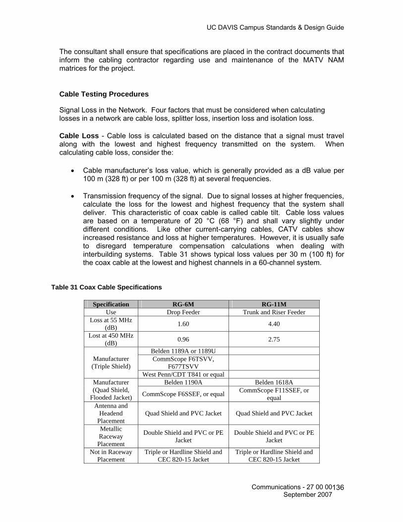
UC DAVIS Campus Standards & Design Guide
The consultant shall ensure that specifications are placed in the contract documents that inform the cabling contractor regarding use and maintenance of the MATV NAM matrices for the project. Cable Testing Procedures Signal Loss in the Network. Four factors that must be considered when calculating losses in a network are cable loss, splitter loss, insertion loss and isolation loss. Cable Loss - Cable loss is calculated based on the distance that a signal must travel along with the lowest and highest frequency transmitted on the system. When calculating cable loss, consider the:
• Cable manufacturer’s loss value, which is generally provided as a dB value per 100 m (328 ft) or per 100 m (328 ft) at several frequencies.
• Transmission frequency of the signal. Due to signal losses at higher frequencies,
calculate the loss for the lowest and highest frequency that the system shall deliver. This characteristic of coax cable is called cable tilt. Cable loss values are based on a temperature of 20 °C (68 °F) and shall vary slightly under different conditions. Like other current-carrying cables, CATV cables show increased resistance and loss at higher temperatures. However, it is usually safe to disregard temperature compensation calculations when dealing with interbuilding systems. Table 31 shows typical loss values per 30 m (100 ft) for the coax cable at the lowest and highest channels in a 60-channel system.
Table 31 Coax Cable Specifications
Specification RG-6M RG-11M
Use Drop Feeder Trunk and Riser Feeder Loss at 55 MHz
(dB) 1.60 4.40
Lost at 450 MHz (dB) 0.96 2.75
Belden 1189A or 1189U CommScope F6TSVV,
F677TSVV Manufacturer (Triple Shield)
West Penn/CDT T841 or equal Belden 1190A Belden 1618A Manufacturer
(Quad Shield, Flooded Jacket) CommScope F6SSEF, or equal CommScope F11SSEF, or
equal Antenna and
Headend Placement
Quad Shield and PVC Jacket Quad Shield and PVC Jacket
Metallic Raceway Placement
Double Shield and PVC or PE Jacket
Double Shield and PVC or PE Jacket
Not in Raceway Placement
Triple or Hardline Shield and CEC 820-15 Jacket
Triple or Hardline Shield and CEC 820-15 Jacket
Communications - 27 00 00 September 2007
136

UC DAVIS Campus Standards & Design Guide
Splitter Loss - The insertion loss for a splitter is a direct function of the quantity of output ports. The higher the quantity of ports, the higher the insertion loss of each port. Insertion Loss - Insertion loss is a measure of the attenuation of a signal between the input and output of a passive device. The unit of measure for insertion loss is the dB. The insertion loss for directional couplers and tap-offs is determined by the tap value. The lower the tap values the higher the insertion loss. Isolation Loss - Isolation loss is loss associated with a tap. Each tap in a system reduces the signal from the trunk or feeder by a specific loss value, expressed in decibels. A properly designed system shall provide a signal level between 3 dBmv and 10 dBmv to every MATV WAO on all channels.
Test and report on each intermediate cabling segment, including BDF/IDF to MATV WAO. Test each end-to-end cable link. Performance Testing involves two steps:
• Aligning/balancing the system - Aligning and balancing the system involves adjusting the gain, tilt and/or sensitivity of the system’s amplifiers (launch and distribution) to match the specified signal levels in the system design. The system’s performance cannot be analyzed until this aligning and balancing is completed.
• Testing the system and its components - Testing the system involves using the
appropriate test equipment to ensure that the system (sweep and levels) and all its components meet the overall design specifications. The test equipment used should include, but is not limited to, a wide band oscilloscope, sync/test generator, RF generator, field strength meter (5-1000 MHz), spectrum analyzer (5-1000MHz), precision demodulator, true RMS audio digital volt-ohm millimeter, signal level meters (SLM) and time domain reflectometers (TDR). Generally, impedance, TDR and structural return loss tests are performed as a pre-installation check of the cable. Testing for signal uniformity is performed on installed cable using a SLM unit.
The tests should ensure that the system and its components meet the specifications for:
• Distortion. • Signal Uniformity • Signal-to-Noise Ratio (SNR) • Signal Ingress • Hum Modulation
Communications - 27 00 00 September 2007
137

UC DAVIS Campus Standards & Design Guide
Performance Requirements The MATV system shall meet the following performance requirements:
1. Compliance with Title 47, Code of Federal Regulations, Part 76, Cable Television
Rules and Regulations.
2. Provide interference-free distribution of any of the scheduled UC Davis channels and allow for future distribution of internally generated forward and reverse channels.
3. Provide CATV compatible adjacent channel operation with bandwidth to at least
1000 MHz. Bandwidth of amplifiers shall be from 49 MHz to 1000 MHz in the forward direction, unless otherwise indicated.
4. Passive elements shall permit upstream (reverse channel) transmission of 5 MHz
to 36 MHz sub-low band VHF television channels from the Headend to any MATV WAO.
5. Output levels of +6 to +12 dBmv from 54 MHz to 450 MHz nominal. +3 dBmv at
output levels above 450 MHz. Tap off output level shall not exceed +15dBmV.
6. Signal level from any channel to any adjacent channel shall not vary more than 2 dB at the tap off location.
7. Long term variations in amplitude shall not exceed 3 dB.
8. Amplitude response within any channel shall not exceed +1.0 dB. 9. Amplitude response for the entire spectrum sector shall not exceed +/- 2 dB.
10. Visual carrier to noise ration shall not be less than 50 dB.
11. Composite triple beat ratio shall not be less than 55 dB.
12. Cross modulation ratio shall not be less then 57 dB.
13. Visual carrier to hum modulation ratio shall not be less than 63 dB.
14. Visual carrier to reflections ratio shall not be less than 46 dB.
Communications - 27 00 00 September 2007
138

UC DAVIS Campus Standards & Design Guide
800 MHz IN-BUILDING RADIO SYSTEMS 27 60 00 The Design Process This chapter establishes the policies and procedures regarding 800 MHz in-building amplified radio systems required in new campus buildings. This chapter also covers the multi-level building needs assessment, specifications, type, cost evaluation, testing and acceptance of an in-building radio system. General Radio Communications Coverage All buildings are required to support radio communications from the local public safety entities (Campus Fire, Police etc.) This section provides standards and guidance in support of the 800 MHz in-building radio communications systems. All capitol building projects exceeding 5,000 square feet (to include multi-level structures) are required to install, at a minimum, an amplification system on the first floor and basement. Additional performance coverage tests shall be performed before and during the construction phase to determine if additional in-building amplification is required for adequate coverage throughout the entire building. Definitions BTS – Base Transceiver Station also known as the donor site. DBm – Decibels, in milli-watts. A unit of measure for RF signal level. Distributive Antenna – A system of non-radiating cable connected to an array of passive antenna. Donor – Base Transceiver Station also known as the donor site. Donor channel – The frequency in which the donor site transmits digital control information. Grade of Service – Typical service is stated as 95% coverage, 95% calls received and transmitted at Circuit Merit Level 3 (CM3). Reference Table 8-1, Circuit Merit Rating. Off–Air Repeater – A repeater that receives frequencies from an antenna and amplifies and retransmits those frequencies. NPSPAC – National Public Safety Planning and Advisory Committee. FCC – Federal Communications Commission. Cross Modulation Ratio – The ratio of aural carrier level to coherent spurious signal level (i.e. inter-modulation products).
Communications - 27 00 00 September 2007
139

UC DAVIS Campus Standards & Design Guide
Carrier to Noise Ratio: The ratio of carrier to noise levels derived from 800 MHz in-building repeater measurements under design load at maximum output over the entire range of the specified frequency response. IBAS – In-Building Amplification System General All buildings or structures located on the UC Davis campus shall support the clients of the UC Davis 800 MHz in-building trunked communications system. This standard also pertains to additions to existing buildings or structures of more than 20%. The clients of this communications system includes, but is not limited to, campus firefighters, police officers and emergency response personnel. Adequate radio coverage shall include all of the following:
1. Installation of an IBAS system in the basement and first floor of qualified buildings to assure a minimum signal strength of –95 dBm in 95% of the area of each floor when transmitted from the campus central transceiver.
2. A minimum signal strength of -95 dBm available in 95% of the area of each
additional floor of a building or structure when transmitted from the campus central transceiver.
3. A minimum signal strength of -95 dBm received at the campus central
transceiver when transmitted from 95% of the area of all floors of a building.
4. The frequency range shall be 821-823 MHz and 866-868 MHz.
5. Radio frequency circuits of 50 ohms to shield and signal ground with Vertical Standing Wave Radio (VSWR) not to exceed 1.5 to 1.
6. 100% reliability.
Amplification Systems. Buildings and structures shall be equipped with:
1. An internal multiple antenna system with FCC type accepted bi-directional 800 MHz amplifiers.
2. Radiating cable system (leaky coax).
3. An independent battery and/or generator system capable of providing at least
twelve (12) hours of external power. The battery system shall automatically charge in the presence of an external power input.
4. Bi-directional amplifiers shall include filters to reduce adjacent frequency
interference at least 35 dB below the NPSPAC band, if required. The filters shall be tuned to 825 and 870 MHz for operation, 35 dB below the NPSPAC frequencies of 824 and 869 MHz, respectively. Other frequency settings shall be
Communications - 27 00 00 September 2007
140
UC DAVIS Campus Standards & Design Guide
used should these fail to attenuate the NPSPAC frequencies by more than one MHz.
5. Reference Table 33 for required antenna specifications.
6. A 1-inch conduit shall be dedicated from the equipment/telecommunications
room (ER/TR) to a sealed junction box on the roof of the building for use as an antenna access point. This conduit shall be grounded using a path other than the telecommunications ground provided in the ER/TR.
Evaluation Process The evaluation process for determining the need for additional in-building amplification on floors beyond the basement and first floor shall be conducted in a minimum of two phases: Pre-construction and construction. Pre-construction Phase Before the construction of the new building, basic information shall be gathered to begin the process of determining the type and actual implementation of an augmented radio system. In most cases, the following information shall be obtained to properly design and costs estimate an in-building radio system. New Building Information:
• Type/Size of building – single story, multi-level, square footage. • If multi-level, number of stories. • Orientation of building – above/below ground, line of sight. • Construction of exterior and interior walls. – Plaster, drywall, brick. • Proposed equipment locations – Equipment rooms, cableways and conduits. • Building location - Longitude and latitude coordinates. • Systems located in basement areas (below ground). • Verification of the riser antenna cable path from the basement area to the roof is
required. The installation of a line-of-site antenna to the campus 800MHz tower shall be required.
• Building blueprints or drawings. Existing System Information:
• BTS location – Longitude and latitude coordinates. • Donor channel frequency – Specific digital channel to enhance radio coverage. • Grade of service required to meet the objective. • Type of subscriber unit. • Number of channels and their frequencies. • Signal strength of donor site at the building location.
With the information above, the following steps shall establish a determination of the potential need for additional in-building radio system amplification beyond the basement and first floor.
Communications - 27 00 00 September 2007
141
UC DAVIS Campus Standards & Design Guide
Need Determination - Signal Strength Measurements: At the planned construction site, measure (or have measured) the signal strength of the donor control channel:
1. If the signal strength of the donor is –95 dBm or less on the outside of the building, the probability of additional in-building coverage beyond the basement and first floor is high.
2. If the signal strength of the donor is greater than –95 dBm, determine the
expected signal strength of the donor by subtracting the sum of the interior losses, due to walls, doors and windows, from the ambient signal outside the building. (See Table 34)
3. If a signal strength of -95 dBm or greater is calculated at the inner most point of
the building, additional coverage on floors beyond the basement and first floor may not be required.
4. If the signal strength is calculated at –95 dBm or less, an in-building system is
warranted on all floors. Construction Phase As the construction progresses, refinements to the initial multi floor system estimate shall be made to ensure that the proposed IBAS will provide adequate coverage and to re-evaluate the impact on existing structures. A re-evaluation of the initial specifications shall help to fine-tune the proposed system size. Testing and Acceptance Once implemented, the IBAS system shall be tested via the pre-determined Acceptance Test Plan (ATP). The ATP shall include personnel from Information and Educational Technology, Communications Resources, campus police, fire, safety and the vendor representative. A walk through test shall be completed and any discrepancies noted and resolved by the vendor. Upon completion of the project installation, it shall be the A&E Project Manager’s responsibility to have the radio system tested to ensure that two-way coverage on each floor of the building are within the general policy requirements as prescribed below8:
1. Each floor of the building shall be divided into a grid of approximately twenty (20) equal areas.
2. The test shall be conducted using a Motorola MTS 2000, or equivalent, portable
radio, talking through the campus central transceiver. The radio shall be attached to the hip via a belt loop and equipped with an extension speaker/microphone and stubby quarter wave whip antenna.
8 Overall project management of the implementation of an in-building coverage system should be offered and included in the turnkey proposal submitted.
Communications - 27 00 00 September 2007
142

UC DAVIS Campus Standards & Design Guide
3. A spot located approximately in the center of a grid area shall be selected for the
test.
4. The radio shall be keyed to verify two-way communications to and from the outside of the building through the campus central transceiver.
5. Once the spot has been selected, prospecting for a better spot within the grid
area shall not be permitted.
6. Each grid area shall be tested for transmission/reception, minimum signal strength of –95 dBm. If signal strength fails to meet the requirement, the grid area shall be marked as a fail.
7. A maximum of two (2) nonadjacent areas shall be allowed to fail the test. In the
event that three (3) of the areas fail the test, the floor shall be divided into forty (40) equal areas. This shall provide for a more statistically accurate test.
8. In such event, a maximum of four (4) nonadjacent areas shall be allowed to fail
the test.
9. Should the system continue to fail after the forty (40) area tests, the A&E project manager shall have the system altered to meet the 95% coverage requirement.
10. The gain values of all amplifiers shall be measured and the test measurement
results shall be kept on file with Communications Resources so that the measurements can be verified each year during the annual tests. In the event the measurement results become unavailable, the building owner shall be required to rerun the acceptance test to reestablish the gain values.
11. In addition to the radio set test listed above, a Radio Frequency Time Domain
Reflectometer (RFTDR) with an operating range of 800-900 MHz and/or a Vertical Standing Wave Radio (VSWR) measurement test set shall also be used to provide a demonstrated conformance test result to Communications Resources.
Qualifications of Testing Personnel Communications Resources shall be responsible for conducting or contracting system tests. All tests shall be conducted, documented and signed by a person in possession of a current FCC license, or a current technician certified by the Associated Public-Safety Communications Officials International (APCO) or the Personal Communications Industry Association (PCIA). All test records shall be retained on the inspected premises and a copy submitted to Communications Resources and the campus Police/Fire Department officials.
Communications - 27 00 00 September 2007
143

UC DAVIS Campus Standards & Design Guide
Table 32 OES/ACS Circuit Merit Rating System The California Governor’s Office of Emergency Services (OES) Auxiliary Communications
Service (ACS) Circuit Merit Rating System
Rating Transmission Quality
CM 5 Completely clear, each word fully understood.
CM 4 Clear with slight amount of static and/or interference.
CM 3 Static and/or interference present, but the bulk of the transmission is understood without having to be repeated. Deemed to be the margin of acceptable, professional communications.
CM 2 Static and interference are prevalent and words are missing.
CM 1 Signal is barely evident and words are not understandable.
CM 0 Nothing heard
Table 33 Antenna Specifications
ITEM SPECIFICATIONS
Frequency Range 806 to 896 MHz
Gain over Isotropic 11 dB
VSWR Not to exceed 1.4 to 1
Horizontal Beam width 90 degree ± 5 degrees at –3 dB relative to normal axis
Vertical Beam width 30 degrees ± 2 degrees at –3 dB relative to normal axis
Front to Back Ratio 20 dB
Polarization Vertical
Maximum Power Input 250 watts at operation frequency
Termination Type N female connector, exit at rear or bottom
Lighting Protection All metal parts grounded.
Dimensions Not to exceed 30-inches high, 8-inches wide, 4-inches deep
Maximum Exposed Area 2.0 square feet
Maximum Wind Speed Survival Not less than 125 MPH
Back Panel Passivated aluminum
Radiating Elements Irradiated aluminum and brass or metal with equal weather resistance
Radome ABS plastic
Mounting Hardware Galvanized steel with attachment to vertical pipe, 2-inch schedule 40
Net weight Not to exceed 10 pounds
Preferred and Recommended Manufacturer
Decibel Products DB862H90
Communications - 27 00 00 September 2007
144

UC DAVIS Campus Standards & Design Guide
Table 34 RF Loss Characteristics
ITEM Loss from Structured Components LOSS (dB)
Ceiling Duct 1-8 Metal Pole (small) 3 Metal Catwalk 5 Large I-Beam 8-10 Concrete Block Wall 13-20 One Floor 20-30 One Floor and One Wall 40-50 Machinery Light Machinery 1-4 Metallic Hoppers 3-6 General Machinery (10-20 sq ft) 5-10 Heavy Machinery (>20 sq ft) 10-15 Inventory Light Textile 3-5 Empty Cardboard 3-6 Metal Inventory 4-7 Heavy Textile 8-11
Table 35 In-building RF Coverage System Cost Estimating
ITEM COST
Coax Cable Installed Antenna Installed Amplifier Low Power Installed Amplifier High Power Installed
Communications - 27 00 00 September 2007
145

UC DAVIS Campus Standards & Design Guide
APPENDIX B Reference Materials Following is a list of reference material on telecommunications infrastructure: ANSI/TIA/EIA-526-7 (June 2003), Measurement of Optical Power Loss of Installed Single-mode Fiber Cable Plant. The intent of this procedure is to ensure that meaningful data describing the optical loss performance of installed single-mode cable plant can be obtained. It is not intended for component testing, nor does it define those elements of an installation that shall be measured. ANSI/TIA/EIA-526-14A (August 2003), Optical Power Loss Measurements of Installed Multimode Fiber Cable Plant. The intent of this procedure is to ensure that meaningful data describing the optical loss performance of installed single-mode cable plant can be obtained. It is not intended for component testing, nor does it define those elements of an installation that shall be measured. ANSI/TIA/EIA-568-B-1 (May 2001), Commercial Building Telecommunications Cabling Standard, Part 1, General Requirements provides rules and guidelines for the physical design of a cabling infrastructure that supports voice and data transmissions in a multi-product, multi-vendor environment. The standards specify a cabling system with a physical star topology. This topology provides economic benefits in terms of initial cabling costs, ongoing maintenance and administration costs. The standards specify copper and fiber optic cable by parameters that determine performance. They also identify connectors and their pin assignments to ensure inter-connectivity. The standards specify maximum allowable distances within the various elements of a cabling system.
• 568-B.1-1 Addendum 1, Minimum 4-Pair UTP and 4-Pair ScTP Patch Cable
Bend Radius (August 2001) • 568-B.1-2 Addendum 2, Ground and Bonding Specification for Screened Balance
Twisted Pair Horizontal Cabling (February 2003) • 568-B.1-3 Addendum 3, Supportable Distance and Channel Attenuation for
Optical Fiber Applications by Fiber Type (February 2003) • 568-B.1-4 Addendum 4, Recognition of Category 6 and 850nm Laser Optized
50/125µm Multimode Optical Fiber Cabling (February 2003) • 568-B. 1-5 Addendum 5, Telecommunications Cabling for Telecommunications
Enclosures (March 2004). • 568-B.2 Part 2: 100 Ohm Balanced Twisted Pair Cabling Components (May
2001) • 568-B.2 Errata Changes to 568-B.2 (Not Dated) • 568-B.2-1 Part 2: Balanced Twisted-Pair Cabling Components Addendum 1,
Transmission Specification for 4-Pair 100 Ohm Category 6 Cabling (June 2002) • 568-B.2-2-Part 2: Balanced Twisted-Pair Cabling Components Addendum 2,
Balance Twisted Pair Cabling Components (December 2001) • 568-B.2-3 Part 2: Balanced Twisted-Pair Cabling Components Addendum 3,
Additional Considerations for Insertion Loss and Return Loss Pass/Fail Determination (March 2002)
Communications - 27 00 00 September 2007
146

UC DAVIS Campus Standards & Design Guide
• 568-B.2-4 Part 2: Balanced Twisted-Pair Cabling Components Addendum 4, Solder less Connection Reliability Requirements for Copper Connecting Hardware (June 2002)
• 568-B.2-5 Part 2: Balanced Twisted-Pair Cabling Components Addendum 5: Corrections to TIA/EIA 568-B.2 (January 2003)
• 568-B.3 Optical Fiber Cabling Components Standard (April 2000) • 568-B.3-1 Additional Transmission Performance Guidelines for 50/125mm
Optical Fiber Cabling (April 2002)
ANSI/EIA/TIA-569-B (November 2004), Commercial Building Telecommunications Pathways and Spaces, describes design and construction practices for pathways and spaces to support telecommunications media and equipment within and between buildings. Standards are for the design of horizontal and work area pathways, building entrance facilities, telecommunications closets and equipment rooms.
ANSI/TIA/EIA-570-A (October 1999), Residential Telecommunications Cabling Standard. The purpose of this document is to standardize requirements for residential telecommunications cabling. These requirements are based on the facilities that are necessary for existing and emerging telecommunications services. Within this standard, services are correlated to grades of cabling for residential units. The cabling infrastructure specifications within this standard are intended to include support for voice, data, video, multimedia, home automation systems, environmental control, security, audio, television, sensors, alarms and intercom. This standard is intended to be implemented for new construction, additions and remodeled single and multi-tenant residential buildings.
• 570-A-1 Addendum 1 - Security Cabling for Residences (March 2002) • 570-A-2 Addendum 2 - Control Cabling for Residences (July 2002) • 570-A-3 Addendum 3 – Whole-Home Audio Cabling for Residences (March
2002) ANSI/TIA/EIA–587 (October 1996), Fiber Optic Graphic Symbols. ANSI/TIA/EIA-598-B (December 2001), Optical Fiber Cable Color Coding defines the recommended identification scheme or system for individual fibers, fiber units or groups of fiber units within a cable structure. The method may be used to identify appropriate fibers for the purpose of connection or termination within a communication system or the topography of long haul, feeder route and subscriber or distribution applications for both on-premises and outside plant use. ANSI/TIA/EIA-606-A (May 2002), Administration Standard for the Telecommunications Infrastructure of Commercial Buildings. This standard specifies administration for a generic telecommunications cabling system that will support a multi-product, multi-vendor environment. It also provides information that may be used for the design of administration products. This standard provides a uniform administration approach that is independent of applications, which may change several times throughout the life of the telecommunications infrastructure. It establishes guidelines for owners, end users, manufacturers, consultants, contractors, designers, installers and facilities administrators involved in the administration of the telecommunications infrastructure. Use of this standard is intended to increase the
Communications - 27 00 00 September 2007
147
UC DAVIS Campus Standards & Design Guide
value of the system owner’s investment in the infrastructure by reducing the labor expense of maintaining the system, by extending the useful economic life of the system and by providing effective service to users. ANSI-J-STD-607-A (October 2002), Commercial Building Grounding (Earthing) and Bonding Requirements for Telecommunications, describes a standard method for distributing signal ground throughout a building. These standards provide the requirements for a ground reference for telecommunications systems within the telecommunications entrance facility, the telecommunications closet, and the equipment room. They also specify the requirements for bonding and connecting pathways, cable shields, conductors and hardware at telecommunications closets, equipment rooms and entrance facilities. The grounding and bonding approach recommended in this Standard is intended to work in concert with the cabling topology as specified in ANSI/TIA/EIA-568-B.1-B.3 (Commercial Building Telecommunications Cabling Standard), pathways as specified in ANSI/TIA/EIA-569-B (Commercial Building Standard for Telecommunications Pathways and Spaces), administration as specified in ANSI/EIA/TIA-606-A (Administration Standard for the Telecommunications Infrastructure of Commercial Buildings) and customer owned outside plant as specified in TIA-758-A (Customer Owned Outside Plant). The requirements specified in this Standard, in conjunction with a basic understanding of grounding and bonding concepts and methodologies will aid the user in achieving a reliable electrical solution when applied to specific telecommunications installations. TIA-758-A (September 2004), Customer-Owned Outside Plant Telecommunications Infrastructure Standard specifies minimum requirements for customer-owned OSP telecommunications facilities in a campus environment. The standard specifies the cabling, pathways and spaces to support the cabling. Customer-owned OSP cabling extends between separated structures including the terminating connecting hardware at or within the structures. The OSP pathway includes the pathway through the point of entry into the building space. Customer-owned OSP pathways may include aerial, direct-buried, underground (e.g., duct) and tunnel distribution techniques. Customer-owned OSP pathways and spaces specified by this standard are intended to have a useful life in excess of forty (40) years. The OSP cabling specified by this standard is intended to support a wide range of applications (e.g., voice, data, video, alarms, environmental control, security, audio, etc.) on commercial, industrial, institutional and residential sites. The customer-owned OSP cabling specified by this standard is intended to have a useful life in excess of thirty (30) years. This standard applies to all campuses, regardless of the size or population.
TIA-Telecommunications Systems Bulletin (TSB) 140 (February 2004), Additional Guidelines for Field-Testing Length, Loss and Polarity of Optical Fiber Cabling Systems. This TSB describes field-testing of length, optical attenuation and polarity in optical fiber cabling using an optical loss test set (OLTS), optical time domain reflectometer (OTDR) and a visible light source such as a visual fault locator (VFL). The purpose of this document is to clarify, not replace, ANSI/TIA/EIA-526-7 and ANSI/TIA/EIA-526-14A. CALIFORNIA ELECTRIC CODE (CEC 2001), CODE OF REGULATIONS, TITLE 24, PART 3. This document incorporates, by adoption, the 1999 edition of the National Electrical Code® of the National Fie Protection Association with the California amendments.
Communications - 27 00 00 September 2007
148

UC DAVIS Campus Standards & Design Guide
CALIFORNIA BUILDING CODE (CBC 2001), CODE OF REGULATIONS, TITLE 24, PART 2, VOLUME 1 AND 2. This document incorporates, by adoption, the 1997 edition of the uniform Building Code® of the International Conference of Building Officials with necessary California amendments. ANSI/NFPA-70: National Electrical Code® (NEC 2005). A set of codes governing items such as voltage limits, transmission media conductor size, over voltage protection requirements, fire resistance of cables and cabling methods. It is important to check with local governing bodies to determine if their codes supersede the NEC articles. IEEE National Electrical Safety Code® (NESC 2002). This standard covers basic provisions for safeguarding of persons from hazards arising from the installation, operation or maintenance of conductors and equipment in electric supply stations and overhead and underground electric supply and communication lines. It also includes work rules for the construction, maintenance and operation of electric supply and communication lines and equipment. Underwriters Laboratories (UL), LAN Cable Certification Program. Test products to verify that performance meets or exceeds industry standards. The UL tests the electrical shock, flame spread and smoke production characteristics of cables. The UL also tests cables for transmission properties. Building Industry Consulting Service International® (BICSI®) Telecommunications Distribution Methods Manual (TDMM), 11th Edition.
BICSI® Customer-Owned Outside Plant (CO-OSP) Design Manual, 4th Edition BICSI® Network Design Reference Manual, 6th Edition. BICSI® Wireless Design Reference Manual, 2nd Edition. California Public Utilities Commission (CPUC) General Orders 95 and 128. Copies of the ANSI/EIA/TIA/NESC industry standards may be purchased from Global Professional Publications, 15 Inverness Way East, Englewood, Colorado 80112- 5776, (800) 854-7179 or (714) 261-1455. http://www.global.ihs.com/ BICSI® TDMM, CO-OSP and Network Design Manuals can be purchased from BICSI, 8610 Hidden River Parkway, Tampa, Florida, 33637-1000, and (800) 242-7405. http://www.bicsi.org/ NEC book can be obtained through the National Fire Protection Association (NFPA), Batterymarch Park, Quincy, MA 02269, and (617) 770-3000. http://www.nfpa.org/ UL LAN Cable Certification Program publication is available from UL, Literature Stock, 333 Pfingsten Road, Northbrook, IL 60062-2096, (708) 272-8800 ext. 43731. http://www.ul.com/lancable
Communications - 27 00 00 September 2007
149

UC DAVIS Campus Standards & Design Guide
California Public Utilities Commission, 505 Van Ness Avenue, San Francisco, CA, (415) 703-1170. http://www.cpuc.ca.gov/ California Building Standards Commission, 2525 Natomas Park Drive, Ste. 130, Sacramento, CA. 95833-2936 Federal Aviation Administration. FCC Docket 21006—Frequency Accuracy. Washington, D.C. Federal Communications Commission. Code of Federal Regulations (CFR)—10CFR47, Part 76.605. Signal Quality for CATV. Washington, D.C. Institute of Electrical and Electronics Engineers, Inc. Standards and Guidelines. New York, NY. National Fire Protection Association, Inc. National Electrical Code® 2002 ed. Quincy, MA.
Society for Cable Telecommunications Engineers, Inc., Exton, PA. Society of Motion Picture and Television Engineers (SMPTE), 595 West Hartsdale Avenue, White Plains, NY. 10607 Audio Engineering Society (AES), International Headquarters, 60 East 42nd Street, Room 2520, New York, NY. 10165 Electrical Industries Association of Japan (EIAJ) International Electrotechnical Commission (IEC), 3, rue de Varembé, P.O. Box 131, CH - 1211 GENEVA 20, Switzerland
Communications - 27 00 00 September 2007
150

UC DAVIS Campus Standards & Design Guide
Appendix C Definitions Access floor: A system consisting of completely removable and interchangeable floor panels that are supported on adjustable pedestals or stringers (or both) to allow access to the area beneath. Administration: The method for labeling, identification, documentation and usage needed to implement moves, additions and changes of the telecommunications infrastructure. Aerial cable: Telecommunications cable installed on aerial supporting structures such as poles, sides of buildings and other structures. Alternate entrance: A supplementary entrance facility into a building using a different routing to provide diversity of service and for assurance of service continuity. Architectural assemblies: Walls, partitions or other barriers that are not load bearing. Architectural structures: Walls, floors, floor/ceilings and roof/ceilings that are load bearing. Area Distribution Frame (ADF): A Telecommunications Space (Equipment or Telecommunications Room) that houses digital loop carrier, network switching and video electronic equipment, as well as, outside plant cable termination hardware for a specific serving area on the UC Davis campus. Backbone: A-facility (e.g., pathway, cable or conductors) between telecommunications closets or floor. Barriers (Architectural): Architectural structures or assemblies. Bonding: The permanent joining of metallic parts to form an electrically conductive path that will ensure electrical continuity and the capacity to conduct safely any current likely to be imposed. (TIA) Building core: A three-dimensional space permeating one or more floors of the building and used for the extension and distribution of utility services (e.g., elevators, washrooms, stairwells, mechanical and electrical systems and telecommunications) throughout the building. Building Distribution Frame (BDF): A Telecommunications Space (Equipment or Telecommunications Room) that houses digital loop carrier, network switching, video electronic equipment, outside plant, riser and horizontal cable termination hardware for the building in which the BDF room is located. In addition, a BDF may also serve a number of smaller Intermediate Distribution Frames (IDF’s) located within the same building and/or IDF’s located outside of the building and within the immediate area on the UC Davis campus.
Communications - 27 00 00 September 2007
151

UC DAVIS Campus Standards & Design Guide
Buried cable: A cable installed under the surface of the ground in such a manner that it cannot be removed without disturbing the soil. Cabinet (telecommunications): A container that may enclose connection devices, terminations, apparatus, wiring and equipment. (TIA) Cable: An assembly of one or more conductors or optical fibers, within an enveloping sheath, constructed so as to permit use of the conductors singly or in groups. Cabling: A combination of all cables, wire, cords and connecting hardware. Campus: The buildings and grounds having legal contiguous interconnection. Ceiling distribution system: A distribution system that utilizes the space between a suspended or false ceiling and the structural surface above. Closet (telecommunications): A recognized location of the cross-connect between the backbone and horizontal facilities. This term has been replaced with the term Telecommunications Room Conduit: A raceway of circular cross-section. Connecting hardware: A device providing mechanical cable terminations. Consolidation point: A location for interconnection between horizontal cables extending from building pathways and horizontal cables extending into furniture pathways. Core area: See building core, Cross-connect: A frame or space that enables the termination of cable elements and their interconnection or cross-connection of these cable elements, or both, by the use of a patch cord or jumper. Cross-connection: A connection scheme between cable runs, subsystems and equipment using patch cords or jumpers to attach to connecting hardware on each end. Device (as related to a work area): An item such as a telephone, personal computer or a graphic or video terminal. Distribution frame: A structure with terminations for connecting the cabling of a facility in such a manner that interconnections or cross-connections may be readily made.
a) Main – when the structure is located at the entrance facility or main cross-connect and serves the building or campus.
b) Intermediate – when the structure is located between the main cross-connect and the telecommunications room.
Distribution terminals: the entrance facilities and the equipment rooms within or between buildings.
Communications - 27 00 00 September 2007
152

UC DAVIS Campus Standards & Design Guide
Emergency power: A stand-alone secondary electrical supply source not dependent upon the primary electrical source. End user: The owner or user of the premises cabling system. Entrance point (telecommunications): The point of emergence of telecommunications conductors through an exterior wall, a concrete floor slab or from a rigid metal conduit or intermediate metal conduit. Entrance room or space (telecommunications): A space, wall or location in which public and private service cables, to include antennae, enter a building and continue to the equipment or telecommunications room or space. NOTE – An entrance room or space may also serve as an equipment or telecommunications room. Equipment room (telecommunications): A centralized space for telecommunications equipment that serves the occupants of the building. False ceiling: See suspended ceiling. Fire stop: A material, device, or assembly of parts installed in a cable pathway at a fire-rated wall or floor to prevent passage of flame, smoke or gases through the rated barrier (e.g., between cubicles or separated rooms or spaces), fire stop seals: See fire stop system. Fire stop system: A specific construction consisting of the material(s) (fire stop penetration seals) that fill the opening in the wall or floor assembly and any items that penetrate the wall or floor, such as cables, cable trays, conduit, ducts, pipes and any termination devices, such as electrical outlet boxes, along with their means of support. Fire stopping: The process of installing specialty materials into penetrations in fire-rated barriers to reestablish the integrity of the barrier. Floor slab: That part of a reinforced concrete floor which is carried on beams below, Furniture cluster: A contiguous group of work areas, typically including space divisions, work surfaces, storage and seating. Ground: A conducting connection, whether intentional or accidental, between an electrical circuit (e.g., telecommunications) or equipment and the earth or to some conducting body that serves in place of earth. Grounding conductor: A conductor used to connect the grounding electrode to the building’s main grounding bus bar. Grounding electrode: A conductor, usually a rod, pipe or plate (or group of conductors) in direct contact with the earth for the purpose of providing a low-impedance connection to the earth.
Communications - 27 00 00 September 2007
153

UC DAVIS Campus Standards & Design Guide
Hand hole: A structure similar to a small maintenance hole in which it is expected that a person cannot enter to perform work. Header duct; trench, feeder duct: A raceway of rectangular cross-section placed within the floor to tie distribution duct(s) or cell@) to the telecommunications closet. Home runs: A pathway or cable between two locations without a point of access in between. Horizontal cabling: The cabling between and including the telecommunications outlet/connector and the horizontal cross-connect. Hybrid cable: An assembly of two or more cables, of the same or different types or categories, covered by one overall sheath. Infrastructure (telecommunications): A collection of those telecommunications components, excluding equipment, that together provides the basic support for the distribution of all information within a building or campus. Innerduct: Typically, a nonmetallic pathway within a pathway. Also known as sub duct. Insert: An opening into the distribution duct or cell, from which the wires or cables emerge. Interconnection: A connection scheme that employs connecting hardware for the direct connection of a cable to another cable without a patch cord or jumper. Intermediate cross-connect: A cross-connect between first level and second level backbone cabling. Intermediate Distribution Frame (IDF): A Telecommunications Space (Telecommunications Room) that houses network switching and video electronic equipment, as well as, outside plant, riser and horizontal cable termination hardware for the building in which the IDF room is located on the UC Davis campus. Jumper: An assembly of twisted pairs without connectors, used to join telecommunications circuits/links at the cross-connect. Main cross-connect: A cross-connect for first level backbone cables, entrance cables and equipment cables. Main distribution frame: See distribution frame. Main terminal room: The location of the cross-connect point of incoming cables from the telecommunications external network and the premises cable system. Maintenance hole (telecommunications): A vault located in the ground or earth as part of an underground duct system and used to facilitate placing, connectorization and maintenance of cables, as well as the placing of associated equipment, in which it is expected that a person will enter to perform work. NOTE – This term has replaced the term “manhole”.
Communications - 27 00 00 September 2007
154

UC DAVIS Campus Standards & Design Guide
Media, telecommunications: Wire, cable or conductors used for telecommunications. Membrane penetration: An opening through only one surface or side of the barrier. Monolithic pour: The single, continuous pouring of a concrete floor and columns of any given floor of a building structure. Minimum Point of Entry (MPOE) The MPOE is the point at which the network facilities provided by the service provider or utility stop, and the property owner’s facilities begin. It also referred to as the Minimum Point of Presence (MPOP). Multi-user telecommunications outlet assembly (MUTOA): A grouping in one location of several telecommunications work area outlets. Network Access Modules (NAM): A UC Davis term to identify a voice, data, FTTD and/or video jack or module. Open office: A floor space division provided by furniture, moveable partitions or other means instead of by building walls. Optical fiber cable: An assembly consisting of one or more optical fibers. Outlet box (telecommunications): A metallic or nonmetallic box mounted within a wall, floor or ceiling and used to hold telecommunications outlets/connectors or transition devices. Outlet/connector (telecommunications): A connecting device in the work area, on which horizontal cable terminates. Also see NAM. Patch cord: A length of cable with connectors on one or both ends used to join telecommunications circuits at the cross-connect. Pathway: A facility for the placement of telecommunications cable. Penetration: An opening in a fire-rated barrier. Plenum: A compartment or chamber to which one or more air ducts are connected and that forms part of the air distribution system. Poke-thru system: Penetrations through the fire resistive floor structure to permit the installation of horizontal telecommunications cables. Pull cord or pull wire: A cord or wire placed within a raceway and used to pull wire and cable through the raceway. Raceway: Any enclosed channel designed-for holding wires or cables. Service entrance: See entrance facility (telecommunications). Service equipment (power): The necessary equipment, usually consisting of a circuit breaker or switch and fuses, and their accessories, located near the point of entrance of
Communications - 27 00 00 September 2007
155

UC DAVIS Campus Standards & Design Guide
supply conductors to a building or other structure (or an otherwise defined area) and intended to constitute the main control and means of cutoff of the (electrical) supply. Sheath: See cable sheath. Slab on grade: Concrete floor placed directly on soil, without basement or crawlspace. Sleeve: An opening, usually circular, through the wall, ceiling or floor to allow the passage of cables. Slot: An opening through a wall, floor, or ceiling, usually rectangular, to allow the passage of cables. Space (telecommunications): An area used for housing the installation and termination of telecommunications equipment and cable, e.g., equipment and telecommunications room, work areas and maintenance holes/hand holes. Splice: A joining of conductors, generally meant to be permanent, generally from separate sheaths. Splice box: A box, located in a pathway run, intended to house a cable splice. Suspended ceiling: A ceiling that creates an area or space between ceiling material and the structure above. Telecommunications: Any transmission, emission, and reception of signs, signals, writings, images, and sounds, that is information of any nature by cable, radio, optical or other electromagnetic systems, Telecommunications room/closet: See closet (telecommunications). Telecommunications entrance facility: See entrance facility (telecommunications). Telecommunications equipment room: See equipment room (telecommunications). Telecommunications infrastructure: See infrastructure (telecommunications). Telecommunications media: See media (telecommunications), Telecommunications outlet: See outlet connector and work area outlet (WAO). Telecommunications service entrance: See entrance facility (telecommunications). Telecommunications space: See space (telecommunications). Terminal:
a) A point at which information may enter or leave a communications network.
b) The input-output associated equipment. c) A device by means of which wires may be connected to each other.
Termination hardware: This term is outmoded. See connecting hardware.
Communications - 27 00 00 September 2007
156
UC DAVIS Campus Standards & Design Guide
Through penetration: A continuous opening that passes through both surfaces of a fire-rated barrier. Topology: The physical or logical arrangement of a telecommunications system. Tunnel: An enclosed passageway usually placed between buildings, for use by people, the distribution of utility services or both. Under floor raceway: A pathway placed within the floor and from which wires and cables emerge to a specific floor area. Usable floor space: Floor space, which is capable of being used as a work area. Utility column: An enclosure pathway extending from the ceiling to furniture or to the floor, which forms a pathway for electrical wiring, telecommunications cable or both. Work Area Outlet (WAO): A wall-mounted or surface-mounted faceplate or box containing a voice, data, FTTD and/or video NAM or any combination thereof.
Communications - 27 00 00 September 2007
157

UC DAVIS Campus Standards & Design Guide
Abbreviations A or AMP ampere ac alternating current ADA Americans with Disabilities Act ADF Area Distribution Frame A&E Architects & Engineers AFF above finished floor AHJ authority having jurisdiction
AHU air handling unit AIA American Institute of A&Es ALPETH aluminum polyethylene AMEP Architectural, mechanical, electrical, and plumbing ANSI American National Standards Institute AP access point AP access provider ASTM American Society for Testing and Materials AWG American wire gauge B or Bur buried BACnet Building Automation and Control network BAS building automation systems BC bonding conductor BD building distributor BDF Building Distribution Frame BEF building entrance facility BER bit error rate BICSI ® Building Industry Consulting Service International bit binary digit BMS building management system b/s bit per second Btu British thermal unit CA cable CAD computer- aided design CAM computer- aided manufacturing CATV community antenna television (cable television) CB conduit bank CBC coupled bonding conductor CBC® California Building Code CEC® California Electrical Code CCTV closed circuit television CD construction documents CEV controlled environment vault CF cellular floor ckt circuit CL closet CLEC competitive local exchange carrier CM construction manager CMP communications plenum cable
Communications - 27 00 00 September 2007
158

UC DAVIS Campus Standards & Design Guide
CMR communications riser cable CO central office coax coaxial cable CP consolidation point CPE customer premises equipment CPE customer provided equipment CPVC chlorinated polyvinyl chloride CSI Construction Specifications Institute CT cable tray DB direct- buried DB ductbank DCE data circuit- terminating equipment DD design development DL ductliner (innerduct) DP demarcation point DTE data terminal equipment EF entrance facility EIA Electronic Industries Alliance EIB European installation bus EM electromagnetic EMI electromagnetic interference EMS energy management system EMT electrical metallic tubing ENT electrical non-metallic tubing EP entrance point ER equipment room e/w equipped with °F degree Fahrenheit FA fire alarm FACP fire alarm control panel FDR feeder FEP fluorinated ethylene propylene FEXT far-end crosstalk FPN fine print note ga gauge Gb/s gigabit per second GIS geographic information system gnd ground GPS global positioning system GRI graded refraction index h hour H horizontal HC horizontal cross-connect HH handhole HVAC heating, ventilating, and air-conditioning Hz hertz
Communications - 27 00 00 September 2007
159
UC DAVIS Campus Standards & Design Guide
IC intermediate cross-connect ID inside diameter IDC insulation displacement connector IDF Intermediate Distribution Frame IEEE ® Institute of Electrical and Electronics Engineers, Inc. IG isolated ground IR infrared ISP inside plant IXC interexchange common carrier kb kilobit kb/s kilobit per second kHz kilohertz km kilometer KTS key telephone system kW kilowatt kWh kilowatt hour LAN local area network lbf pound-force LEC local exchange carrier (now service provider [SP]) MAC move, add, or change MB megabyte Mb/s megabit per second MC main cross- connect MDF main distribution frame MH maintenance hole MHz megahertz MM multimode MUTO multi-user telecommunications outlet MUTOA multi-user telecommunications outlet assembly N newton NAM Network Access Module NEC ® National Electrical Code ® NEMA ® National Electrical Manufacturers Association ® NFPA ® National Fire Protection Association ® NIC network interface card NRTL national recognized testing laboratory OC outlet cable OD outside diameter Ohm Ω OSP outside plant OTDR optical time domain reflectometer PB pull box PBX private branch exchange PE polyethylene
Communications - 27 00 00 September 2007
160

UC DAVIS Campus Standards & Design Guide
POTS plain old telephone service (colloquial) PP polypropylene pr pair PSTN public switched telephone network PVC polyvinyl chloride RCDD ® Registered Communications Distribution Designer RUS Rural Utilities Services RFI request for information RFP request for proposal RFQ request for quote RMS rack mounting space RNC rigid non-metallic cable ScTP screened twisted- pair SD schematic design SFF small form factor SHF super high frequency SL sleeve SM single-mode ST slot STALPETH steel, aluminum, polyethylene STP shielded twisted- pair TB terminal block TBB telecommunications bonding backbone TBBIBC telecommunications bonding backbone interconnecting bonding
conductor TC telecommunications closet (see telecommunications room) T&C terms and conditions TDD telecommunications device for the deaf TEF telecommunications entrance facility TEL telephone TELCO telephone company TERM terminal or terminating TGB telecommunications grounding busbar TIA Telecommunications Industry Association TMGB telecommunications main grounding busbar TR telecommunications room TT telephone terminal TTB telephone terminal board TTY teletypewriter/text telephone UBC uniform building code UG underground UL ® Underwriters Laboratories Inc. ® UPS uninterruptible power supply V vertical WA work area
Communications - 27 00 00 September 2007
161

UC DAVIS Campus Standards & Design Guide
WAN wide area network WAO work area outlet WW wireway
Communications - 27 00 00 September 2007
162