Embed Size (px)
Citation preview

DIVISION 27 - COMMUNICATIONS Section Title Number
Technical Standards Revised 03/01/2012
1 of 29
27 00 00 COMMUNICATIONS 27 01 00 Operation and Maintenance of Communication Systems 27 01 10 Operation and Maintenance of Structure Cabling Enclosures 27 01 20 Operation and Maintenance of Data Communications 27 01 30 Operation and Maintenance of Voice Communications 27 05 00 Common Work Results for Communications 27 05 13 Communication Services NAU – CATV System 27 05 26 Grounding and Bonding for Communication Systems 27 05 28 Pathways for Communications Systems Hangers and Support for Communication Systems Conduits and Back Boxes for Communications Systems Cable Trays for Communications Systems Surface Raceways for Communications Systems Furniture Raceways and Pathways 27 05 43 Underground Ducts and Raceways for Communications Systems 27 10 00 STRUCTURED CABLING 27 11 00 Communications Equipment Room Fittings 27 11 13 Communications Entrance Protection 27 11 16 Communications Cabinets, Racks, Frames, and Enclosures 27 11 19 Communications Termination Blocks and Patch Panels 27 11 23 Communications Cable Management and Ladder Rack 27 11 26 Communications Rack Mounted Power Protection and Power Strips 27 13 00 Communications Backbone Cabling 27 13 13 Communications Copper Backbone Cabling Building Copper Backbone Inter Building Copper Cable Backbone Communications Copper Cable Splicing Copper Cable Testing 27 13 23 Communications Optical Fiber Backbone Cabling Building Optical Fiber Cable Backbone Inter Building Optical Fiber Cable Optical Fiber Splicing and Terminations and Testing 27 15 00 Communications Horizontal Cabling Voice Communications Horizontal Cabling Data Communications Horizontal Cabling 27 15 43 Communication Faceplates and Connectors 27 16 00 Communications Connecting Cords, Devices, and Adapters 27 16 13 Communications Custom Cable Assemblies 27 16 16 Communications Media Converters, Adapters, and Transceivers 27 16 19 Communications Patch Cords, Station Cords, and Cross Connect Wires
DIVISION 27 - COMMUNICATIONS Section Title Number
Technical Standards Revised 03/01/2012
2 of 29
27 20 00 DATA COMMUNICATIONS 27 21 00 Data Communications Network Equipment 27 30 00 VOICE COMMUNICATIONS 27 31 00 Voice Communications Switching and Routing Equipment 27 32 00 Voice Communications Telephone Sets, Facsimiles, and Modems 27 32 23 Elevator Telephones 27 32 26 Ring-Down Emergency Telephones 27 33 00 Voice Communications Messaging 27 34 00 Call Accounting 27 35 00 Call Management 27 40 00 AUDIO-VIDEO COMMUNICATIONS

DIVISION 27 - COMMUNICATIONS Section Title Number
Technical Standards Revised 03/01/2012
3 of 29
27 00 00 COMMUNICATIONS 27 01 00 Operation and Maintenance of Communication Systems
It is the responsibility of Information Technology Services (ITS) to insure that a fully compliant and efficient communication infrastructure is in place for the universities needs. These standards are in place to accomplish that goal. These standards are developed for the use of all campus departments as well as all Architects, Developers and Contractors involved in construction on NAU campus. Cost for materials and installation of all Telecomm related items should be part of the Project Budget. Coordination with NAU/ITS is required prior to actual construction and wiring placement. Elevator and emergency telephones shall be included in the project and installed by the contractor. Manufacturer and model number pre-approved by ITS.
Approved Contractor Requirements A. The Telecommunications Contractor shall be an approved Hubbell or
Leviton Certified Installer. B. A copy of the certification documents must be submitted with the quote. C. The System Installer must have an RCDD approve the project design D. A Hubbell or Leviton System Performance Warranty covering all
components, equipment and workmanship shall be submitted in writing with system documentation.
E. Should the cabling system fail to perform its expected operation within the warranty period due to inferior or faulty material and/or workmanship, the contractor shall promptly make all required corrections without cost to Northern Arizona University.
F. System shall be complete Hubbell or Leviton system it should not be a combination of the two.
Codes and Standards Compliance A. All materials shall comply with the most current applicable sections of the
following Codes for installation of telecommunications cabling: 1. International Building Code (IBC) 2. National Electrical Code (NEC/NFPA 70) 3. National Electrical Safety Code (NESC IEEE C 2) 4. Local Codes, amendments, and ordinances.
B. All materials and installation practices shall comply with the applicable sections of the following Telecommunications Industry Standards: 1. ANSI/TIA/EIA-568-B.1, Commercial Building Telecommunications
Cabling Standard, Part 1: General Requirements.
DIVISION 27 - COMMUNICATIONS Section Title Number
Technical Standards Revised 03/01/2012
4 of 29
2. ANSI/TIA/EIA-568-B.2, Commercial Building Telecommunications Cabling Standard, Part 2: Balanced Twisted-Pair Cabling Components.
3. ANSI/TIA/EIA-568-B.3, Commercial Building Telecommunications Cabling Standard, Part 3: Optical Fiber Cabling Components Standard.
4. ANSI/TIA/EIA-568-B.2-1: Transmission Performance Specification for 4-Pair 100 Ω Category 6 Cabling (Standard).
5. ANSI/TIA/EIA-569-A (Including 5 addendums), Commercial Building Standards for Telecommunications Pathways and Spaces
6. ANSI/EIA/TIA-570, Residential and Light Commercial Telecommunications Wiring Standard
7. ANSI/TIA/EIA-606, The Administration Standard for the Telecommunications infrastructure of Commercial Building
8. ANSI/TIA/EIA-607, Commercial Building Grounding and Bonding Requirements for Telecommunications
9. ANSI/TIA/EIA-758, Customer Owned Outside Plant Telecommunications Cabling Standard
C. Installers shall have read the above documents and shall be familiar with the requirements that pertain to this installation. The documents may be obtained from: 1. Global Engineering Documents, 15 Inverness Way East, Englewood,
CO, 80112-5776, 800-854-7179, fax: 303-397-2740, http://global.his.com/
2. IEEE-Institute of Electrical and Electronics Engineers, Inc., 345 East 47th Street, New York, NY, 10017-2394, 800-678-IEEE, fax: 732-981-9667, http://standards.ieee.org/
For any questions or further information on ITS cabling standards please contact Danny Henderson 928-523-7009, [email protected]
27 01 10 Operation and Maintenance of Structured Cabling Enclosures
The operation and maintenance of all structured cabling systems are the responsibility of NAU/ITS and any and all changes or modification shall be coordinated with NAU/ITS.
27 01 20 Operation and Maintenance of Data Communications
The operation and maintenance of all data communications are the responsibility of NAU/ITS and any and all changes or modification shall be coordinated with NAU/ITS
DIVISION 27 - COMMUNICATIONS Section Title Number
Technical Standards Revised 03/01/2012
5 of 29
27 01 30 Operation and Maintenance of Voice Communications
The operation and maintenance of all voice communications are the responsibility of NAU/ITS and any and all changes or modification shall be coordinated with NAU/ITS
27 05 00 Common Work Results for Communications 27 05 13 Communication Services
All Voice and Data Communication Services to be supplied by or coordinated with NAU/ITS. This includes dial tone services, T1 services, DSL services, Network services.
NAU – CATV Systems Cable Television Equipment and Signal
All distribution equipment "Line Powered" shall be a 60-90 volt AC Quasi-square wave signal or “premise” powered with 115VAC. The system shall meet or exceed all technical standards set forth in FCC Rules, Part 76. Forward bandwidth of all passive devices shall be a minimum of (1) GHz with full reverse (upstream) capacity. The ratio of visual signal levels to coherent disturbances such as intermodulation products, second and third order distortions or discrete-frequency interfering signals shall not be less than (-51dB). Carrier-to-noise ratio shall be 48dB minimum. System radiation (CLI) shall meet all FCC requirements of Part 76: Rules and Regulations. Isolation between any two outlets in the system shall be a minimum of 18dB. All room outlets in the system shall provide a minimum level of +3dBmv and a maximum level of +12dBmv. The RF level deference between any two adjacent channels shall be no greater than 3dB.
Drop Cable
RG-6 series with minimum 67% braid; 18 AWG 0.040" copper covered steel center conductor; gas expanded foam type dielectric (FEP); inner shield aluminum laminated tape with overlap bonded to dielectric; outer shield of 34 AWG bare aluminum braid wire; jacket of plenum rated material. CROSS REFERENCE: Belden #1530AP or CommScope #2276V. NOTE: Metal wall plates required for all housing projects.
Feeder Cable
500 P3 series copper clad aluminum center conductor: expanded polyethylene dielectric; solid aluminum sheath; outer jacked of black high molecular weight polyethylene. CROSS REFERENCE: CommScope #P-3 Series.
DIVISION 27 - COMMUNICATIONS Section Title Number
Technical Standards Revised 03/01/2012
6 of 29
Trunk Cable/Fiber 750 P3 series copper clad aluminum center conductor; expanded polyethylene dielectric; solid aluminum sheath; outer jacket of black high molecular weight polyethylene. CROSS: REFERENCE: CommScope #P-3 75-750 JCA. Fiber; single-mode.
Connectors
Drop; RG-6 compression type, Feeder; .500 pintype Gilbert #GRS 500CH-DU-03 Trunk; .750 pintype Gilbert #GRS 750CH-DU-03, Fiber; SC/APC or FC/APC (min.65dB return-loss).
Distribution Amplifiers/Nodes
Distribution/Node amplifiers shall have a minimum forward bandwidth of 860MHz with full reverse (upstream) capacity. Manufacturer of CATV equipment and material shall be determined during preliminary project planning. Spare (standby) opto-electronic/electronics shall be provided at completion of project. All equipment shall be installed in equipment rooms on each floor of each wing, all cable drops shall be home runs to the equipment room on that floor and labeled with its corresponding room number.
Note: Design maps shall be included in project budget and provided prior to, during and at completion of project.
27 05 26 Grounding and Bonding for Communications Systems
All building and Communication grounding to conform to the following codes, standards, and practices: NFPA 70 of NEC, ANSI J-STD-607-A, IEEE, latest edition of BICII method manual and all applicable National, State and Local building codes.
A Telecommunications Main Grounding Bus bar (TMGB) connected to the Electrical Grounding System is required in all buildings. All communication equipment spaces require a Telecommunication Grounding Bus bar (TGB) connected to the TMBG and bonded to approved building ground. All connections bonded with a minimum 6 AWG conductor. All cable tray, equipment racks, and equipment cabinets bonded to TGB. All Telecommunication protectors and associated metallic cable sheaths to be grounded to selected TGB with a minimum 14 AWG insulated conductor. All copper pairs to be protected at building entrance facility with gas tube type 350VDC protector modules.
27 05 28 Pathways for Communications Systems
All communication cabling shall be routed in a designed and approved pathway system per ANSI/TIA/EIA-569-B, (Commercial Building Standard for
DIVISION 27 - COMMUNICATIONS Section Title Number
Technical Standards Revised 03/01/2012
7 of 29
Telecommunications Pathways and Spaces) and meet or exceed all National, State and Local codes and standards. Design shall be documented in floor plans and have built in flexibility for tenant movement and expansion and designed for maintenance and relocation of cables as easy as possible.
Hangers and Support for Communications Systems
All cable supports shall be located on maximum of 48" on center. All cable supports rated for Category 6 structured cabling system. In a ceiling distribution design a minimum of 3" clearance between ceiling tile and cable should be maintained. All hangers and supports must be suspended from or attached to the structural ceiling or walls with hardware designed to support their load bearing rating. Only Velcro type cable ties shall be used for dressing or securing Category 6 Cabling.
Conduits and Back Boxes for Communication Systems
All conduits to be rigid, flexible conduit is not acceptable for any application. Design and installation of conduits should be run in most direct route possible with no more than two 90 degree bends and should not contain any electrical condulets (LB’s). Conduit should not be placed over or adjacent to boilers, incinerators, hot water lines or steam lines. Conduits 2" or smaller require a bend radius of 6 times the internal conduit diameter, more than 2"require 10 times the internal conduit diameter. All conduit ends should be reamed and fitted with insulated bushing. Specify a minimum two 1” conduits to each office type room on opposite walls. All other rooms (labs, classrooms, etc.) require consultation with NAU/ITS. Conduit to terminate in a 4"x4" double gang box with 4" square single device cover and routed to communication cable tray or stubbed to accessible location. Equip all conduits with a pull cord that has a minimum test rating of 200 lb. All conduits dedicated to communication structured cabling system and shall not be shared with any other services.
Cable Trays for Communications Systems
Type and design of cable tray distribution system shall be pre-approved by NAU/ITS. Cable tray installation must be installed to meet NEC article-392 and all state and local codes. Cable tray should be dedicated to telecommunication use only and not shared with electrical. Design should be such that all requirements for a certified Category 6 structured cabling system will be met i.e. bend radius, clearances and distances etc. Cable tray to be sized so as not to exceed the allowable fill volume. All metallic cable trays must be grounded and clearly marked in accordance with ANSI/TIA/EIA-606-A and ANSI J-STD-607-A.
DIVISION 27 - COMMUNICATIONS Section Title Number
Technical Standards Revised 03/01/2012
8 of 29
Surface Raceways for Communications Systems
Surface raceway should only be considered as last resort and with prior coordination with NAU/ITS. Raceway design should be of a type that conforms to category 6 certification for bend radius, interference and separation. Raceway must be capable of accepting Hubbell or Leviton wiring products including jacks and faceplates. If electrical power and telecommunications services are both run in raceway separate compartments are required and must comply with applicable electrical codes. If a metallic barrier is provided, it must be bonded to ground. Raceway shall be sized so as not to exceed manufacturers fill rating.
Furniture Raceways and Pathways
All furniture pathways to adhere to ANSI/TIA/EIA-569 current standards. Maximum pathway fill shall be 40%. Minimum size pathway shall not force the cable into a bend radius less than 1" under condition of maximum fill. Any parallel pathway to electrical must have proper separation. All furniture pathways must be capable of accepting Hubbell or Leviton brand termination hardware.
27 05 43 Underground Ducts and Raceways for Communications Systems
See section 33 81 26 for Site communications ducts, manholes under floor ducts systems shall be dedicated space for telecommunication cables and not shared with any other utility. The guideline for planning duct capacity is 1in² of cross section for each 100ft² of useable floor space. Junction boxes shall be placed at a maximum of 60 ft to allow access for cable placement. All distribution ducts must be physically linked to a telecommunication room directly or through no more than one feeder duct. Ducts entering the telecommunications room must terminate in either a slot or elbow.
**END OF SECTION**
DIVISION 27 - COMMUNICATIONS Section Title Number
Technical Standards Revised 03/01/2012
9 of 29
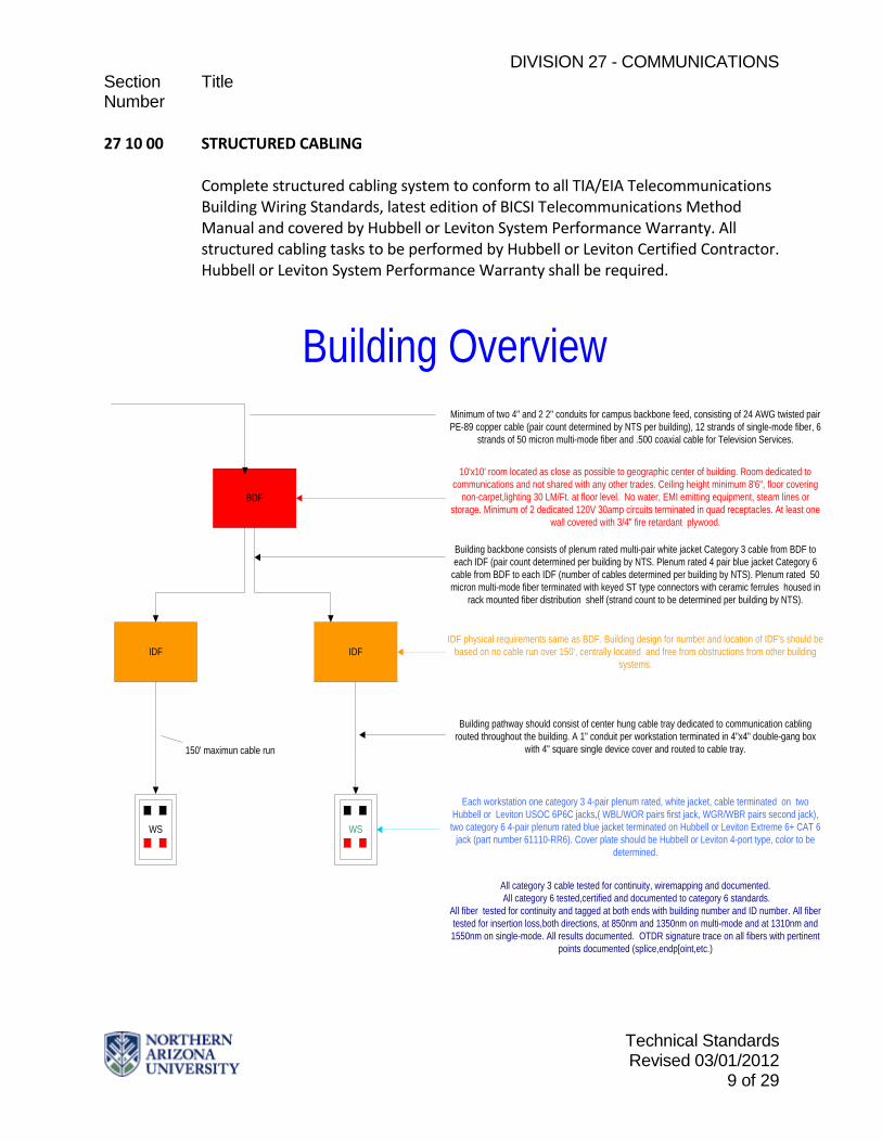
27 10 00 STRUCTURED CABLING
Complete structured cabling system to conform to all TIA/EIA Telecommunications Building Wiring Standards, latest edition of BICSI Telecommunications Method Manual and covered by Hubbell or Leviton System Performance Warranty. All structured cabling tasks to be performed by Hubbell or Leviton Certified Contractor. Hubbell or Leviton System Performance Warranty shall be required.
BDF
IDF IDF
WS WS
Each workstation one category 3 4-pair plenum rated, white jacket, cable terminated on two Hubbell or Leviton USOC 6P6C jacks,( WBL/WOR pairs first jack, WGR/WBR pairs second jack), two category 6 4-pair plenum rated blue jacket terminated on Hubbell or Leviton Extreme 6+ CAT 6
jack (part number 61110-RR6). Cover plate should be Hubbell or Leviton 4-port type, color to be determined.
150' maximun cable run
Minimum of two 4" and 2 2" conduits for campus backbone feed, consisting of 24 AWG twisted pair PE-89 copper cable (pair count determined by NTS per building), 12 strands of single-mode fiber, 6
strands of 50 micron multi-mode fiber and .500 coaxial cable for Television Services.
10'x10' room located as close as possible to geographic center of building. Room dedicated to communications and not shared with any other trades. Ceiling height minimum 8'6", floor covering
non-carpet,lighting 30 LM/Ft. at floor level. No water, EMI emitting equipment, steam lines or storage. Minimum of 2 dedicated 120V 30amp circuits terminated in quad receptacles. At least one
wall covered with 3/4" fire retardant plywood.
Building backbone consists of plenum rated multi-pair white jacket Category 3 cable from BDF to each IDF (pair count determined per building by NTS. Plenum rated 4 pair blue jacket Category 6
cable from BDF to each IDF (number of cables determined per building by NTS). Plenum rated 50 micron multi-mode fiber terminated with keyed ST type connectors with ceramic ferrules housed in
rack mounted fiber distribution shelf (strand count to be determined per building by NTS).
IDF physical requirements same as BDF. Building design for number and location of IDF's should be based on no cable run over 150', centrally located and free from obstructions from other building
systems.
Building pathway should consist of center hung cable tray dedicated to communication cabling routed throughout the building. A 1" conduit per workstation terminated in 4"x4" double-gang box
with 4" square single device cover and routed to cable tray.
Building Overview
All category 3 cable tested for continuity, wiremapping and documented. All category 6 tested,certified and documented to category 6 standards.
All fiber tested for continuity and tagged at both ends with building number and ID number. All fiber tested for insertion loss,both directions, at 850nm and 1350nm on multi-mode and at 1310nm and 1550nm on single-mode. All results documented. OTDR signature trace on all fibers with pertinent
points documented (splice,endp[oint,etc.)

DIVISION 27 - COMMUNICATIONS Section Title Number
Technical Standards Revised 03/01/2012
10 of 29
27 11 00 Communications Equipment Room Fittings
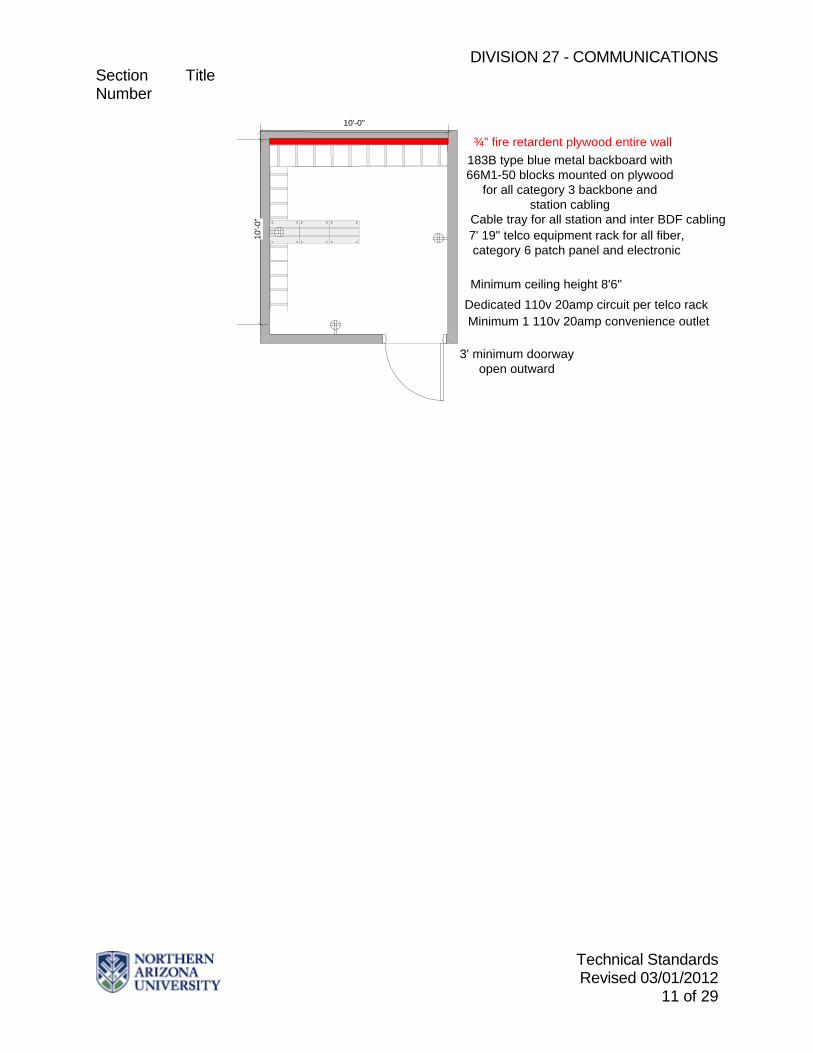
All buildings shall have at least one (depending on building size, footprint and design possibly more) Telecommunications room per floor. Building design shall be such that no horizontal cable run exceeds 150'. Design should be that Telecommunications rooms are as close to the core of the building as possible. Multiple story buildings should be designed so that Telecommunications rooms are stacked. A minimum of two 4"conduits from each room to main BDF is required. The space shall be dedicated to Telecommunications equipment and not shared with electrical or any other building system. Equipment not related to the support of telecommunications closet (e.g., piping, ductwork, etc.) shall not be installed in, pass through, or enter the telecommunications room. Minimum size shall be 10'X10' with a minimum of 8' 6"clearance height with solid ceiling. Wall finish shall be light in color. Lighting shall be a minimum of 500 lx measured 3ft. above finished floor. Room shall be environmentally controlled to maintain operating range of 65°F to 75° F 24/7. Flooring shall be static free, no carpeting. Power requirements are based on individual building design and need approval of NAU/ITS but a minimum of 2 20amp quad convenience outlets are required. Each Telecommunications room shall be equipped with a grounding bus bar connected to the building TGB. One complete wall shall be covered with 3/4" fire rated A-C plywood painted to match interior. Entrance door shall be minimum of 36" opening outward. Backbone and horizontal cable pathways shall terminate into room. Room cable management shall consist of ladder tray above all wall mount frames and all equipment racks.
DIVISION 27 - COMMUNICATIONS Section Title Number
Technical Standards Revised 03/01/2012
11 of 29
¾” fire retardent plywood entire wall183B type blue metal backboard with 66M1-50 blocks mounted on plywood
for all category 3 backbone and station cabling
Cable tray for all station and inter BDF cabling
3' minimum doorway open outward
7' 19" telco equipment rack for all fiber, category 6 patch panel and electronic
Minimum ceiling height 8'6"Dedicated 110v 20amp circuit per telco rackMinimum 1 110v 20amp convenience outlet
10'-0
"
10'-0"
DIVISION 27 - COMMUNICATIONS Section Title Number
Technical Standards Revised 03/01/2012
12 of 29
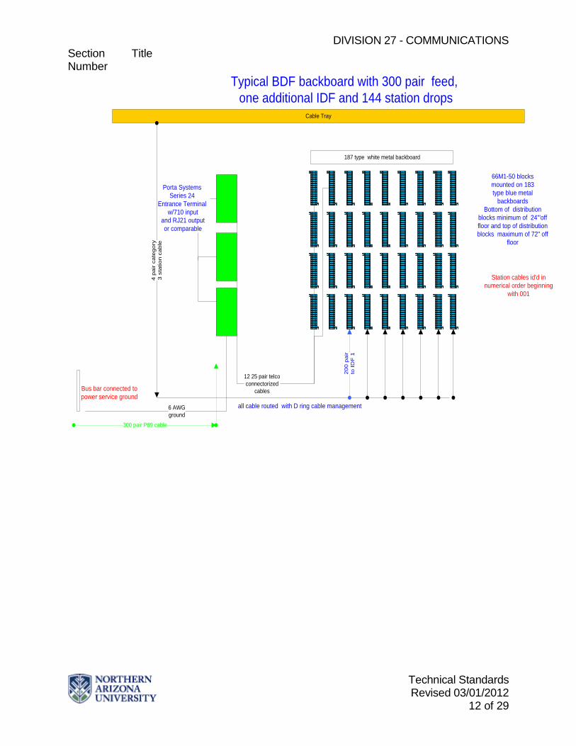
12 25 pair telcoconnectorized
cables
Typical BDF backboard with 300 pair feed, one additional IDF and 144 station drops
187 type white metal backboard
Cable tray
66M1-50 blocksmounted on 183 type blue metal
backboardsBottom of distribution
blocks minimum of 24'"off floor and top of distribution blocks maximum of 72" off
floor
6 AWGground
all cable routed with D ring cable management
Cable Tray
Bus bar connected topower service ground
300 pair P89 cable
4 pa
ir ca
tego
ry3
stat
ion
cabl
e
200
pair
to ID
F 1
Station cables id'd in numerical order beginning
with 001
Porta Systems Series 24
Entrance Terminal w/710 input
and RJ21 output or comparable
DIVISION 27 - COMMUNICATIONS Section Title Number
Technical Standards Revised 03/01/2012
13 of 29
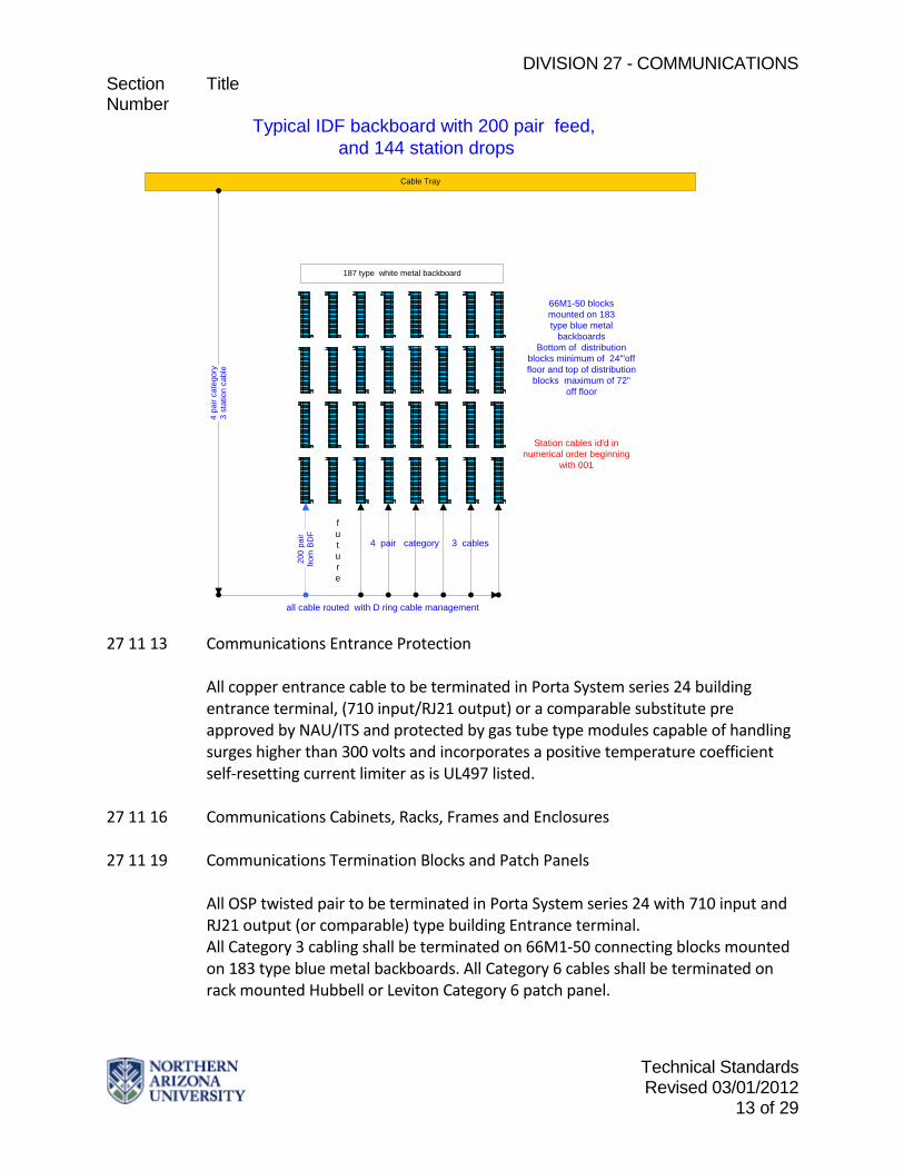
Typical IDF backboard with 200 pair feed, and 144 station drops
187 type white metal backboard
66M1-50 blocksmounted on 183type blue metal
backboardsBottom of distribution
blocks minimum of 24'"offfloor and top of distribution
blocks maximum of 72"off floor
all cable routed with D ring cable management
Cable Tray
4 pa
ir ca
tego
ry3
stat
ion
cabl
e
200
pair
from
BD
F
Station cables id'd innumerical order beginning
with 001
4 pair category 3 cables
future
27 11 13 Communications Entrance Protection
All copper entrance cable to be terminated in Porta System series 24 building entrance terminal, (710 input/RJ21 output) or a comparable substitute pre approved by NAU/ITS and protected by gas tube type modules capable of handling surges higher than 300 volts and incorporates a positive temperature coefficient self-resetting current limiter as is UL497 listed.
27 11 16 Communications Cabinets, Racks, Frames and Enclosures 27 11 19 Communications Termination Blocks and Patch Panels
All OSP twisted pair to be terminated in Porta System series 24 with 710 input and RJ21 output (or comparable) type building Entrance terminal. All Category 3 cabling shall be terminated on 66M1-50 connecting blocks mounted on 183 type blue metal backboards. All Category 6 cables shall be terminated on rack mounted Hubbell or Leviton Category 6 patch panel.
DIVISION 27 - COMMUNICATIONS Section Title Number
Technical Standards Revised 03/01/2012
14 of 29
27 11 23 Communications Cable Management and Ladder Rack
All cable management to conform to industry standards and comply with a Hubbell or Leviton certified Category 6 system. All active and passive rack mount equipment to be separated by horizontal cable management. Vertical cable management required in multiple rack design. Ladder rack required to all racks and for cable entrance into all telecommunication rooms. All wall mount Category 3 cable termination fields require 187 type white metal backboards for cross connect field.
27 11 26 Communications Rack Mounted Power Protection and Power Strips
Minimum of one horizontal power strip 20A/120V with 8 NEMA5-20R receptacles. 27 13 00 Communications Backbone Cabling
See section 33 82 00 for site communications distribution and outside plant requirements. All campus buildings will be fed with twisted pair copper, 8.3 micron single-mode fiber, and 50 micron Laser optimized multi-mode fiber. Number of conductors to be determined by NAU/ITS on a per project basis.
27 13 13 Communications Copper Backbone Cabling Building Copper Backbone
Building voice backbone cabling will consist of multi-pair (100 pair minimum) plenum rated inside cable between BDF and all IDF’s. All cable will be homerun and terminated at both ends on 66M1-50 connecting blocks mounted on blue metal 183 type mounting boards. All pairs tested for continuity, shorts grounds and wire map. Building data backbone will consist of multiple (number to be determined per project by ITS) 4-pair plenum rated blue jacket category 6 cables terminated on Hubbell or Leviton category 6 patch panel. All cables certified at Category 6 specifications and be a registered partner of Hubbell or Leviton for system performance warranty.
Inter Building Copper Cable Backbone
Copper cable shall be PE 39 type and meet the following requirements: • 24 AWG pair count determined by NAU/ITS per project • Cable shall meet the requirements of ANSI/CEA S-84-608 Buried service wire to conform to ANSI/CEA S-86-634. The transmission requirements of connecting hardware used in the OSP shall comply with the connecting hardware requirements of ANSI/TIA/EIA 568-A.

DIVISION 27 - COMMUNICATIONS Section Title Number
Technical Standards Revised 03/01/2012
15 of 29
Communications Copper Cable Splicing
All splicing and splice closures to conform to TIA/EIA-758. All splicing completed with 710 type multiple pair connectors. No bridge-taps and 25-pair binder groups shall not be split between termination points. All splices housed in a closure compatible with all materials used in the construction of cable, filling compounds, bonding and grounding devices, chemicals, and sealants that the closure would come in contact under normal conditions. Closure construction shall be reusable and re-enterable without factory refurbishing. All closures to be filled with filling compound. Replacement parts shall be readily available.
Copper Cable Testing
All twisted pair cable to be tested with complete wire map and 100 % pass rate for following: • DC loop resistance • Wire map • Continuity to remote end • Shorts between two or more conductors • Crossed pairs • Reversed pairs • Split pairs • Any other miss-wiring
27 13 23 Communications Optical Fiber Backbone Cabling
Fiber- SM A germania-doped silica core surrounded by a concentric silica glass cladding shall comprise each optical fiber. The fiber shall be a matched clad design manufactured by the outside vapor deposition process (OVD). Each optical fiber refractive index profile shall be step index. Each fiber shall be proof tested by the fiber manufacturer at a minimum of 100 kpsi (0.7 GN/m²). The fiber shall be coated with a dual acrylate protective coating and the coating shall be in physical contact with the cladding surface. The single-mode fiber shall meet EIA/TIA-492CAAB, “Detail Specification for Class lVa Dispersion-Unshifted Single-Mode Optical Fibers with Low Water Peak,” and ITU-T G.652.C, “Characteristics of Single-Mode Optical Fiber Cable.” Fiber shall have a mode field diameter of 9.20 ± 0.40 µm at 1310 nm and 10.40 ± 0.50 µm at 1550 nm. Fiber core-clad concentricity shall be = 0.5 µm. Fiber cladding diameter shall be 125.0 ± 0.7 µm. Fiber cladding non-circularity shall be = 0.7%. Fiber coating diameter shall be 245 ± 5 µm.
DIVISION 27 - COMMUNICATIONS Section Title Number
Technical Standards Revised 03/01/2012
16 of 29
The attenuation specification shall be a maximum value for each cabled fiber at 23 ± 5°C on the original shipping reel. The cabled fiber attenuation for Loose Tube and Ribbon cable constructions shall be < 0.4 dB/km at 1310 nm and <0.3 dB/km at 1550 nm. For Tight Buffered constructions the cabled fiber attenuation shall be <1.0 dB/km at 1310 nm and <0.75 dB/km at 1550 nm. The attenuation at the water peak (1383 nm) shall not exceed the 1310 nm attenuation value. The cabled fiber shall be capable of operating in the 1360 nm to 1480 nm water peak region. The attenuation due to 100 turns of fiber around a 50 ± 2 mm diameter mandrel shall not exceed 0.05 dB at 1310 nm and 0.10 dB at 1550 nm. The attenuation due to 100 turns of fiber around a 75 ± 2 mm diameter mandrel shall not exceed 0.10 dB at 1625 nm. There shall be no point discontinuities greater than 0.10 dB at 1310 nm and 1550 nm. The maximum dispersion shall be = 3.2 ps/(nm•km) from 1285 nm to 1330 nm and shall be =18 ps/(nm•km) at 1550 nm. The cabled fiber shall support Gigabit Ethernet (GbE) operation according to the 1000BASE-LX (1310 nm) specifications up to 5000 m in accordance with the GbE standard. The cabled fiber shall support laser-based 10 Gigabit Ethernet (10GbE) operation according to the 10GBASE-LX4 (1300 nm region), 10GBASE-L (1310 nm) and 10GBASE-E (1550 nm) specifications for distances of 10 km, 10 km and 40 km, respectively. The cabled optical fiber shall support industry-standard multi-gigabit Fiber Channel physical interface specifications.
Fiber MM 50um Laser Optimized Each fiber in the cable must be usable and meet required specifications. Each optical fiber shall be sufficiently free of surface imperfections and inclusions to meet the optical, mechanical and environmental requirements of this specification. A germania-doped silica core surrounded by a concentric silica glass cladding shall comprise each optical fiber. The fiber shall be a matched clad design manufactured by the outside vapor deposition process (OVD). Each optical fiber shall be proof tested by the fiber manufacturer at a minimum of 100 kpsi (0.7 GN/m²). The fiber shall be coated with a dual-layer acrylate protective coating. The coating shall be in physical contact with the cladding surface. The attenuation specification shall be a maximum value for each cabled fiber at 23 ± 5°C on the original shipping reel. The multimode fiber shall meet TIA-492AAAC, "Detail Specification for 850-nm Laser-Optimized, 50-µm Core Diameter/125-µm Cladding Diameter Class Ia Graded-Index Multimode Optical Fibers." The core diameter shall be 50.0 ± 2.5 µm. The cladding diameter shall be 125.0 ± 2.0 µm. The cladding non-circularity shall be = 1.0%. The core-clad concentricity shall be = 1.5 µm. The coating diameter shall be 245 ± 5 µm. The optical fiber
DIVISION 27 - COMMUNICATIONS Section Title Number
Technical Standards Revised 03/01/2012
17 of 29
refractive index profile shall be graded. The numerical aperture of the fiber shall be 0.200 ± 0.015. The maximum cabled fiber attenuation shall be 3.0 dB/km at 850 nm and 1.0 dB/km at 1300 nm for all cable types. The cabled optical fiber shall have a minimum effective modal bandwidth (EMB) of 2000 MHz•km at 850 nm in accordance with FOTP-220 for 10 Gigabit Ethernet. The cabled optical fiber shall have a minimum over-filled launch (OFL) bandwidth of 1500/600 MHz•km at 850/1300 nm. The cabled optical fiber shall have a minimum restricted mode launch (RML) bandwidth of 1400 MHz•km at 850 nm in accordance with FOTP-204 for Gigabit Ethernet. The cabled optical fiber shall support industry-standard IEEE 802.3 10GBASE-S (10 Gigabit Ethernet at 850 nm) physical layer specifications for 300 m. The cabled optical fiber shall support industry-standard IEEE 802.3 1000BASE-SX (Gigabit Ethernet at 850 nm) physical layer specifications for 1000 m and 1000BASE-LX (Gigabit Ethernet at 1300 nm) for 600 m. The cabled optical fiber shall support industry-standard multi-gigabit Fibre Channel physical interface specifications. There shall be no point discontinuity greater than 0.2 dB. The attenuation coefficient at 1380 nm shall not exceed the attenuation coefficient at 1300 nm by more than 3.0 dB/km. The attenuation due to 100 turns of fiber around a 75 mm diameter mandrel shall not exceed 0.5 dB at 850 nm and1300 nm.
Building Optical Fiber Cable Backbone
Single-Mode and 50 Micron Laser optimized Multi-mode fiber optic backbone required between BDF and all IDF locations. All cable to be homerun with no splices and installed in 1" plenum rated innerduct. Strand count to be determined by NAU/ITS on a per project basis. ISP Cable- MIC 2-24 fibers plenum Cable shall be plenum-rated, all-dielectric, with two to twenty-four 900 ± 50 µm tight-buffered fibers. TBII® Tight-Buffered Fiber shall be made of a PVC material and shall have a UV-cured acrylate coating (low-friction slip layer) between the acrylate coating of the optical fiber and the PVC buffer. The fiber coating, low-friction slip layer and PVC buffer shall be removable with commercially available stripping tools in a single pass for termination or splicing. The individual fibers shall be color-coded for identification. The optical fiber color coding shall be in accordance with TIA/EIA-598-B, "Optical Fiber Cable Color Coding.” Fibers shall be stranded together around jacketed or non-jacketed dielectric strength members via reverse oscillation and surrounded with dielectric strength members and a ripcord. Cables containing 12 to 24 fibers shall have a dual-layer stranded design. The cable jacket color shall be orange for cables containing all multimode fiber, except for cables containing
DIVISION 27 - COMMUNICATIONS Section Title Number
Technical Standards Revised 03/01/2012
18 of 29
50/125 µm, 850 nm laser optimized fiber, which shall have an aqua colored outer jacket. The cable jacket color shall be yellow for cables containing all single mode fiber. Hybrid cables (containing more than one type of fiber) shall have an outer jacket with the color corresponding to the greatest percentage of total fibers within the cable, except for hybrid cables containing 50/125 µm, 850 nm laser optimized fiber, which shall have an aqua colored outer jacket. Unique color identification of all fibers within the hybrid cable shall correspond to fiber core diameter (or mode field diameter) from smallest to largest in accordance with TIA/EIA-598-B. Cable shall be listed OFNP/FT-6 and be fully compliant with ICEA S 83-596. The outer jacket shall be marked with the manufacturer's name or ETL file number, date of manufacture, fiber count, fiber type, flame rating, listing symbol, and sequential length markings every two feet (e.g., “CORNING OPTICAL CABLE - 01/00 – 12 SM – TB2 - OFNP (ETL) OFN FT6 (CSA) 0001 marking shall be in contrasting color to the cable jacket. FEET”). The cable shall have a storage temperature range of -40° to 70°C on the original shipping reel, installation temperature range of 0° to 60°C, and an operating temperature range of 0° to 70°C. Cable manufacturer shall be ISO 9001 registered. _ _ -29. ISP Cable- UMIC 24-144 fibers plenum Cable shall be all-dielectric and contain 36 to 144 900 ± 50 µm tight-buffered fibers. TBII® Tight-Buffered Fiber shall be made of a PVC material and shall have a UV-cured acrylate coating (low friction slip layer) between the acrylate coating of the optical fiber and the PVC buffer. The fiber coating, low friction slip layer and PVC buffer shall be removable with commercially available stripping tools in a single pass for termination or splicing. The individual fibers shall be color-coded for identification. The optical fiber color coding shall be in accordance with TIA/EIA-598-B, "Optical Fiber Cable Color Coding.” Fibers shall be stranded via reverse oscillation with dielectric strength members and a ripcord in either 6-fiber or 12 fiber subunits. Cable with < 60 fibers shall contain 6-fiber sub-units; otherwise cable shall contain 12-fiber subunits. Subunits shall be stranded together in a planetary configuration around a jacketed or bare glass reinforced plastic (GRP) dielectric central member. Cable shall contain a ripcord underneath outer cable jacket to facilitate jacket removal. Each subunit jacket shall be made of a PVC material and shall be identified with a unique number at periodic intervals. Subunit color containing multimode fiber shall be orange. Subunit color containing 50/125 µm, 850 nm laser optimized fiber shall be aqua. Subunit color containing single-mode fiber shall be yellow. A dual-layer subunit design shall be used for cables containing 108 to 144 fibers. The cable jacket color shall be orange for cables containing all multimode fiber, except for cables containing 50/125 µm, 850 nm laser optimized fiber, which shall have an aqua colored outer jacket. The cable jacket color shall be yellow for cables containing all single mode fiber. Hybrid cables (containing more than one type of fiber) shall have an outer jacket with the color corresponding to the greatest percentage of total fibers within the cable, except for hybrid cables

DIVISION 27 - COMMUNICATIONS Section Title Number
Technical Standards Revised 03/01/2012
19 of 29
containing 50/125 µm, 850 nm laser optimized fiber, which shall have an aqua colored outer jacket. Cable shall be listed OFNP/FT-6 and be fully compliant with ICEA S-83-596. Cable outer jacket shall be marked with the manufacturer's name or ETL file number, date of manufacture, fiber count, fiber type, flame rating, listing symbol, and sequential length markings every two feet (e.g., “CORNING OPTICAL CABLE - 01/00 – 72 SM– TB2 - OFNP (ETL) OFN FT6 (CSA) 0001 FEET”). The marking shall be in contrasting color to the cable jacket. Cable shall have a storage temperature range of -40°C to +70°C, installation temperature range of 0°C to +60°C, and an operating temperature range of 0°C to +70°C. Cable manufacturer shall be ISO 9001 registered.
Inter Building Optical Fiber Cable
Fiber Optic cable shall meet following requirements: Cable shall be all-dielectric, stranded loose-tube design with dry waterblocking for outdoor duct and aerial installations in fiber counts from two to 288. Each fiber shall be distinguishable by means of color coding in accordance with TIA/EIA-598-B, "Optical Fiber Cable Color Coding.” The fibers shall be colored with ultraviolet (UV) curable inks. Buffer tubes shall be made from polypropylene. Each buffer tube shall contain a water swellable yarn for water blocking protection. The water-swellable yarn shall be non-nutritive to fungus, electrically non-conductive, and homogeneous. It shall also be free from dirt or foreign matter. This yarn will preclude the need for other waterblocking material; the buffer tube shall be gel free. The optical fibers shall not require cleaning before placement into a splice tray or fan out kit. The buffer tube shall be manufactured to a standard 3.0 mm in size, regardless of fiber count, to reduce the number of required installation and termination tools. Buffer tubes containing fibers shall be color coded with distinct and recognizable colors in accordance with TIA/EIA-598-B. Buffer tube colored stripes shall be inlaid in the tube by means of co extrusion when required. The nominal stripe width shall be 1 mm. Buffer tubes in a hybrid cable (cable containing more than one type of fiber) shall contain only one fiber type. Identification of fiber types in a hybrid cable shall correspond to fiber core diameter (or mode field diameter) from smallest to largest in accordance with TIA/EIA-598-B. Buffer tubes shall be stranded around the dielectric central member using the reverse oscillation stranding process. Two polyester yarn binders shall be applied contra helically with sufficient tension to secure each buffer tube layer to the dielectric central member without crushing the buffer tubes. The binders shall be non hygroscopic, non wicking, and dielectric with low shrinkage. Water swellable yarn(s) shall be applied longitudinally along the central member during stranding. For dual-layer cables, a second (outer) layer of buffer tubes shall be stranded over the original core to form a two-layer core. A water swellable tape shall be applied longitudinally over both the inner and outer layer. The water-swellable tape shall be non-nutritive to

DIVISION 27 - COMMUNICATIONS Section Title Number
Technical Standards Revised 03/01/2012
20 of 29
fungus, electrically non-conductive, and homogenous. It shall also be free from dirt and foreign matter. Cable shall be comprised of water-swellable yarns and/or tapes, dielectric strength members (as required), ripcord(s) and an MDPE jacket containing carbon black to provide ultraviolet light protection while inhibiting the growth of fungus. Cable jacket shall be marked with the manufacturer’s name, month and year of manufacture, sequential meter or foot markings, a telecommunication handset symbol as required by Section 350G of the National Electrical Safety Code® (NESC®), fiber count, and fiber type. The actual length of the cable shall be within -0/+1% of the length markings. The print color shall be white, with the exception that cable jackets containing one or more coextruded white stripes, which shall be printed in light blue. The height of the marking shall be approximately 2.5 mm. Cable shall contain reverse oscillation lay (ROL) markings as needed. Cable shall have a storage temperature range of -40° to 70°C, an installation temperature range of -30? to 70°C, and an operating temperature range of -40° to 70°C. Cable shall have a short-term tensile rating of 2700 N. No fiber strain shall occur over the service life of the cable when subjected to a maximum, long-term tensile rating of 890 N. Cable shall meet the functional requirements of Rural Utilities Service (RUS) 7 CFR 1755.900 and be fully compliant with ICEA S-87-640. Manufacturer shall be ISO 9001 and TL 9000 registered.
Optical Fiber Splicing and Terminations and Testing
Rackmount Housings Housings shall be mountable in an EIA-310 compatible 465- or 592 mm rack. Housings shall be available in both 1U, 2U and 4U sizes. One EIA rack space or panel height (denoted as 1U) is defined as being 44.45 mm in height. The unit shall meet all applicable design requirements listed in ANSI/TIA/EIA-568, ANSI/TIA/EIA-942, and the polymer compounds flammability requirements of UL 94 V-0. Manufacturer shall be ISO 9001 and TL 9000 registered. Housings shall be manufactured using 16-gauge aluminum or equivalent for structural integrity and shall be finished with a rustic gun-metal grey powder coat for durability. All joints shall be welded and finished in a workman-like manner. Installation fasteners shall be included and shall match the housing color. The unit shall include a clamshell-type cable clamping mechanism to provide cable strain-relief. The front and rear doors shall be lockable when used with an optional key lock kit. The Connector Housings shall have a labeling scheme that complies with ANSI/TIA/EIA-606. The housings shall be available with factory-installed connectorized cable stubs in multiple cable and connector types. The housing shall have the ability to accommodate fusion splicing with additional hardware. The housing shall be 16 inches deep for extra cable routing.
DIVISION 27 - COMMUNICATIONS Section Title Number
Technical Standards Revised 03/01/2012
21 of 29
Connectors ST SM Connector shall be compliant with industry standard ANSI/TIA/EIA-568-B.3. The connector shall comply with the TIA/EIA Fiber Optic Connector Intermateability Standard (FOCIS) document, TIA/EIA-604-2. The connector installation shall not require the use of epoxies, adhesives or ovens. The connector shall be installable upon 900 µm buffered fiber in one minute or less and upon 2.9 mm jacketed cable in three minutes or less total time. The connector shall be installable upon single-mode optical fiber. Ferrule material shall be ceramic. The connector crimp on mechanism shall protect the bare fiber from the ingress of air or waterborne contaminants. Connector shall be consistently capable of insertion losses of 0.3 dB (typical) and shall be 0.75 dB (maximum) when installed in accordance with the manufacturer’s recommended procedure and tested in accordance with FOTP-171. Connector reflectance shall be measured after manufacture to be less than or equal to -40/-55 dB for super physical contact (SPC)/ultra physical contact (UPC). Manufacturer shall be ISO 9001 and TL 9000 registered. The manufacturer shall have an in-depth knowledge, and more than 10-year history, of manufacturing and supporting connector technology that does not require epoxy or polishing in the field. Connectors ST MM 50um Connector shall be compliant with industry standard ANSI/TIA/EIA-568-B.3. The connector shall comply with TIA/EIA Fiber Optic Connector Intermateability Standard (FOCIS) document, TIA/EIA-604-2. The connector installation shall not require the use of epoxies, adhesives or ovens. The connector shall be installable upon 900µm buffered fiber in one minute or less and upon 2.9 mm jacketed cable in three minutes or less total time. The connector shall be installable upon 50/125 µm multimode optical fiber. Ferrule material shall be ceramic. The connector crimp on mechanism shall protect the bare fiber from the ingress of air or waterborne contaminants. Connector shall be consistently capable of insertion losses of 0.3 dB (typical) and shall be 0.75 dB (maximum) when installed in accordance with the manufacturer’s recommended procedure and tested in accordance with FOTP-171. Connector reflectance shall be less than or equal to -20 dB. Manufacturer shall be ISO 9001 and TL 9000 registered. Connectors ST MM 50um Laser Optimized Connector shall be compliant with industry standard ANSI/TIA/EIA-568-B.3. The connector shall comply with TIA/EIA Fiber Optic Connector Intermateability Standard (FOCIS) document, TIA/EIA-604-2. The connector installation shall not require the use of epoxies, adhesives or ovens. The connector shall be installable upon 900 µm buffered fiber in one minute or less and upon 2.9 mm jacketed cable in three minutes or less total time. The connector shall be installable upon 850-nm laser-optimized 50 µm multimode optical fiber. Ferrule material shall be ceramic. The connector crimp on mechanism shall protect the bare fiber from the ingress of

DIVISION 27 - COMMUNICATIONS Section Title Number
Technical Standards Revised 03/01/2012
22 of 29
air or waterborne contaminants. Connector shall be consistently capable of insertion losses of 0.3 dB (typical) and shall be 0.75 dB (maximum) when installed in accordance with the manufacturer’s recommended procedure and tested in accordance with FOTP-171. Connector reflectance shall be less than or equal to -20 dB. Manufacturer shall be ISO 9001 and TL 9000 registered. Splice cases The SCF splice closures shall be available in canister (butt) and in-line styles to fit most applications. All end-caps feature two express ports for uncut feeder cables. The Splice Closure Housing shall be non-metallic. It shall be resistant to solvents, stress cracking and creep. The housing materials shall also be compatible with chemicals and other materials to which they might be exposed in normal applications. The optical fiber closure shall be capable of accepting any optical fiber cable commonly used in interoffice, outside plant and building entrance facilities. As an option, the ability to double the cable capacity of an installed canister splice closure by use of a kit shall be available. Such a conversion shall not disturb existing cables or splices. Encapsulation shall not be required to resist water penetration. The splice closure shall be re-enterable. The closure end-cap shall be capable of accepting additional cables without removal of the sheath retention or strength-member-clamping hardware on previously installed cables or disturbing existing splices. The optical fiber splice closure shall provide a clamping mechanism to prevent pistoning of the central member or strength members and to prevent cable sheath slip or pullout. The splice closure shall have appropriate hardware and installation procedures to facilitate the bonding and grounding of metal components in the closure and the armored cable sheath. The cable bonding hardware shall be able to accommodate a copper conductor equal to or larger than 6 AWG. Aerial splice closures shall have available the necessary hardware to attach and secure the closure to an aerial strand. The closure shall accommodate splice trays suitable for single-fiber, single fiber heat-shrink, mechanical or ribbon heat-shrink splices. The small splice closure shall accommodate up to 72 single-fiber splices or 144 ribbon fiber splices using 12-fiber ribbons. The medium-sized closure shall accommodate up to 288 single-fiber splices or 432 ribbon-fiber splices. The large closure shall accommodate up to 480 single-fiber splices or 864 ribbon-fiber splices. The installation of the splice closure shall not require specialized tools or equipment, other than those normally carried by installation crews. All fibers (inter and intra building) tested for continuity and tagged at both ends with building number and ID number. All fibers tested for insertion loss, both directions, at 850nm and 1350nm on multi-mode, and at 1310nm and 1550nm on single-mode. All results documented. OTDR signature trace on all fibers with
DIVISION 27 - COMMUNICATIONS Section Title Number
Technical Standards Revised 03/01/2012
23 of 29
pertinent points documented (splice, endpoints, etc.) Only test results with University personnel present will be accepted.
27 15 00 Communications Horizontal Cabling Voice Communications Horizontal Cabling
All workstations shall be fed by one 4-pair 100 ohm balanced Category 3 plenum rated with white jacket cable. Manufacturer of cable must be partner with Hubbell or Leviton and registered for System Performance Guarantee. No cable run shall exceed 150'. Cable shall be terminated at the work station on two Hubbell or Leviton USOC 6P6C type jacks (wbl-wor pairs on one and wgr-wbr pairs on the other) and terminated at the BDF/IDF on 66M1-50 connecting blocks mounted on blue metal 183 type backboards.
Data Communications Horizontal Cabling
All workstations shall be fed by two 4-pair 100 ohm balanced Category 6 plenum rated with blue jacket cables. All buildings shall be designed for wireless communication with access point coverage of 35 foot diameter per floor. Each wireless point shall consist of one 4-pair 100 ohm balanced Category 6 plenum rated with blue jacket cable. Manufacture of cable must be partner with Hubbell or Leviton and registered for Hubbell or Leviton System Performance Guarantee. No cable run shall exceed 150'. Cable be terminated at workstation on Hubbell or Leviton category 6 jack and terminated at the BDF/IDF on Hubbell or Leviton Category 6 patch panel. All cables tested and certified to Category 6 standard. Computer labs, classrooms, and all other special applications require the input of NAU/ITS on number and location of drops. Only Velcro type cable ties shall be used with Category 6 cabling.
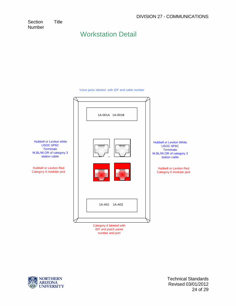
27 15 43 Communications Faceplates and Connectors
Quad telephone faceplates shall be standard at all workstation locations fed by one category three 4-pair and two category 6 4-pairs, (color and material to match electrical plates) with two Hubbell or Leviton category 6 modular jacks (category 6 cable, T568A wiring) and two Hubbell or Leviton USOC 6P6C type jacks (w-bl/w-or pairs of category three cable terminated on one and w-gr/w-br pairs of category three cable terminated on the other.
DIVISION 27 - COMMUNICATIONS Section Title Number
Technical Standards Revised 03/01/2012
24 of 29
Hubbell or Leviton white USOC 6P6C
TerminateW,BL/W,OR of category 3
station cable
Voice jacks labeled with IDF and cable number
Workstation Detail
Hubbell or Leviton Red Category 6 modular jack
Hubbell or Leviton White USOC 6P6C
TerminateW,BL/W,OR of category 3
station cable
1A-001A 1A-001B
1A-A01 1A-A02
Category 6 labeled with IDF and patch panel
number and port
Hubbell or Leviton Red Category 6 modular jack
DIVISION 27 - COMMUNICATIONS Section Title Number
Technical Standards Revised 03/01/2012
25 of 29
27 16 00 Communications Connecting Cords, Devices, and Adapters 27 16 13 Communications Custom Cable Assemblies
All custom built cable assemblies tested and certified to appropriate category level and meet performance level of all applicable codes and standards.
27 16 16 Communications Media Converters, Adapters, and Transceivers
Furnished by NAU/ITS 27 16 19 Communications Patch Cords, Station Cords, and Cross Connect Wire
Patch cords, equipment cords, and work area cords must meet the applicable performance requirements in ANSI/TIA/EIA-568-B.2. All cords associated with the data horizontal cable system must be 4-pair Category 6 rated and factory terminated and shall be included in Hubbell or Leviton System Warranty. All patch cords sized to provide a neat appearance.
**END OF SECTION**
DIVISION 27 - COMMUNICATIONS Section Title Number
Technical Standards Revised 03/01/2012
26 of 29
27 20 00 DATA COMMUNICATIONS 27 21 00 Data Communications Network Equipment
All Data Communication Equipment furnished by NAU/ITS
**END OF SECTION**

DIVISION 27 - COMMUNICATIONS Section Title Number
Technical Standards Revised 03/01/2012
27 of 29
27 30 00 VOICE COMMUNICATIONS 27 31 00 Voice Communications Switching and Routing Equipment
All equipment furnished by NAU/ITS. 27 32 00 Voice Communications Telephone Sets, Facsimiles, and Modems
All telephone sets and ancillary equipment furnished by NAU/ITS except Elevator and Emergency Telephones
27 32 23 Elevator Telephones
Manufacturer shall be RamTel and all models shall be ACA capable. Model must be pre-approved by NAU/ITS.
27 32 26 Ring-Down Emergency Telephones
Manufacturer shall be RamTel and all models shall be ACA capable and pre-approved by NAU/ITS. All site located Emergency phones to be fed by buried service wire meeting ANSI/CEA S-86-634 standard with station protection and routed to the closest Telecommunications equipment room.
27 33 00 Voice Communications Messaging
All services provided and maintained by NAU/ITS 27 34 00 Call Accounting
All services provided and maintained by NAU/ITS 27 35 00 Call Management
All services provided and maintained by NAU/ITS
**END OF SECTION**
DIVISION 27 - COMMUNICATIONS Section Title Number
Technical Standards Revised 03/01/2012
28 of 29
27 40 00 AUDIO-VIDEO COMMUNICATIONS
Cable Television Equipment and Signal All distribution equipment shall be "Line Powered" with a 60 volt AC Quasi-square wave signal. The system shall meet or exceed all technical standards set forth in FCC Rules, Part 76. Band width of all passive and active devices in the forward feed shall be 54 MHz to 750 MHz and 5MHz to 30 MHz in the reverse feed. Amplifiers shall be "Push-Pull” design. The system shall be designed to -57dB or better cross modulation and a carrier-to-noise ratio shall be 46dB minimum. System radiation (CLI) shall meet all FCC requirements of Part 76: Rules and Regulations. Isolation between any two outlets in the system shall be a minimum of 28dB. All room outlets in the system shall provide a minimum level of +3dBmv and a maximum level of +12dBmv. The RF level deference between any two adjacent channels shall be no greater than 2dB.
Drop Cable RG59/u Type, 95% braid coverage 10 AWG: NOM 0.032" copper covered steel center conductor; gas expanded polyethelene dielectric; inner shield aluminum-polypropylene - aluminum laminated tape with overlap bonded to dielectric; outer shield of 34 AWG bare aluminum braid wire; jack of black polyvinylchloride or polyethelene. CROSS REFERENCE: Belden #9108 or comm/scope #F5995BVV
Feeder Cable 500 P3 series copper clad aluminum center conductor: expanded polyethylene dielectric; solid aluminum sheath; outer jacked of black high molecular weight polyethylene. CROSS REFERENCE: Comm/scope #P-3 Series.
Trunk Cable
750 P3 series copper clad aluminum center conductor; expanded polyethylene dielectric; solid aluminum sheath; outer jacket of black high molecular weight polyethelene. CROSS: REFERENCE: comm/scope #P-3 75-750 JCA
Connectors RG59 F-Type Gilbert #GF/59-AHS, Feed .500 pintype Gilbert #GRS 500CH-DU-01 Trunk .750 pintype Gilbert #GRS 750CH-DU-01
Distribution Amplifiers Trunk will be Scientific Alanta series 6500 750MHz sub-split truck station with reverse module. Feeder will be Scientific Alanta 6501/6502 distribution amplifier with reverse module. All 2-port, 4-port, 8-port taps and directional couplers will be Scientific Atlanta. All equipment shall be installed in equipment rooms on each floor of each wing all cable drops shall be home runs to the equipment room on that floor and labeled with its corresponding room number.
DIVISION 27 - COMMUNICATIONS Section Title Number
Technical Standards Revised 03/01/2012
29 of 29
**END OF SECTION**


![Video, Storage, & Networkingspecifiers.blob.core.windows.net/document/SIA_Div28VideoSlidesFin… · 27 15 01.13 Video Surveillance Communications [ ] 27 15 01.15 Access Control Communications](https://img.dokumen.tips/doc/110x75/5f09d4fc7e708231d428b3aa/video-storage-27-15-0113-video-surveillance-communications-27-15-0115.jpg)