Embed Size (px)
Citation preview

255sx - SERVICE 1SERIAL NUMBER
SERVICE
SERIAL NUMBER
Record the serial numbers and date of purchase for your
equipment in the spaces below.
Date of purchase:
Serial number:
Engine serial number:
255sx - SERVICE 1SERIAL NUMBER
SERVICE
SERIAL NUMBER
Record the serial numbers and date of purchase for your
equipment in the spaces below.
Date of purchase:
Serial number:
Engine serial number:

2 255sx - SERVICESUPPORT PROCEDURE
2 255sx - SERVICESUPPORT PROCEDURE
SUPPORT PROCEDURE
Notify your dealer immediately of any malfunction or failure of Ditch Witch equipment.
Always give model, serial number, and approximate date of equipment purchase. This information should be recorded and placed on file by owner at time of purchase.
Return damaged parts to dealer for inspection and warranty consideration.
Order genuine Ditch Witch replacement or repair parts from your authorized Ditch Witch dealer. Use of another manufacturer’s parts may void warranty.
RESOURCES
Publications
Contact your Ditch Witch dealer for publications covering operation, service, and repair of your equipment.
Ditch Witch Training
For information about on-site, individualized training, contact your Ditch Witch dealer.
SUP
Notify Ditch W
Alwaysequipmplaced
Returnconsid
Order authorparts m
RES
Publi
Contacoperat
Ditch
For infDitch W
PORT PROCEDURE
your dealer immediately of any malfunction or failure of itch equipment.
give model, serial number, and approximate date of ent purchase. This information should be recorded and
on file by owner at time of purchase.
damaged parts to dealer for inspection and warranty eration.
genuine Ditch Witch replacement or repair parts from your ized Ditch Witch dealer. Use of another manufacturer’s ay void warranty.
OURCES
cations
t your Ditch Witch dealer for publications covering
ion, service, and repair of your equipment.Witch Training
ormation about on-site, individualized training, contact your itch dealer.
255sx - FOREWORD 3
FOREWORD
This manual is an important part of your equipment. It provides safety information and operation instructions to help you use and maintain your Ditch Witch equipment.
Read this manual before using your equipment. Keep it with the equipment at all times for future reference. If you sell your equipment, be sure to give this manual to the new owner.
If you need a replacement copy, contact your Ditch Witch dealer. If you need assistance in locating a dealer, visit our website at www.ditchwitch.com or write to the following address:
The Charles Machine Works, Inc.Attn: Marketing DepartmentPO Box 66Perry, OK 73077-0066 USA
The descriptions and specifications in this manual are subject to change. The Charles Machine Works, Inc. reserves the right to improve equipment. Some product improvements may have taken place after this manual was published. For the latest information on Ditch Witch equipment, see your Ditch Witch dealer.
Thank you for buying and using Ditch Witch equipment.

4 255sx - FOREWORD 4 255sx - FOREWORD
Operator’s Manual255sx
Issue No. 8.0/OP-2/03Part Number 054-402
Copyright 1984, 1985, 1987, 1989, 1990, 1993, 1996, 1999, 2003
by The Charles Machine Works, Inc.,Perry, Oklahoma
, Ditch Witch, AutoCrowd, Modularmatic, Jet Trac, Roto Witch, Subsite, Fluid Miser, Sidekick, Perma-Soil, Super Witch, Super Witch II, and Pierce Airrow are registered trademarks of The Charles Machine Works, Inc.
CMW, Power Pipe, The Underground, and The Underground Authority Worldwide are pending trademarks of The Charles Machine Works, Inc.
ModulSidekiAirrowInc.
CMW,AuthorMachin
Operator’s Manual255sx
Issue No. 8.0/OP-2/03Part Number 054-402
Copyright 1984, 1985, 1987, 1989, 1990, 1993, 1996, 1999, 2003
by The Charles Machine Works, Inc.,Perry, Oklahoma
, Ditch Witch, AutoCrowd, armatic, Jet Trac, Roto Witch, Subsite, Fluid Miser, ck, Perma-Soil, Super Witch, Super Witch II, and Pierce are registered trademarks of The Charles Machine Works,
Power Pipe, The Underground, and The Underground ity Worldwide are pending trademarks of The Charles e Works, Inc.
255sx - CONTENTS 5
CONTENTS
SERVICE . . . . . . . . . . . . . . . . . . . . . . . . . . . . . . . . . . . . . . . 1
Serial Number . . . . . . . . . . . . . . . . . . . . . . . . . . . . . . . 1
Support Procedure . . . . . . . . . . . . . . . . . . . . . . . . . . . 2
Resources . . . . . . . . . . . . . . . . . . . . . . . . . . . . . . . . . . 2
FOREWORD . . . . . . . . . . . . . . . . . . . . . . . . . . . . . . . . . . . . 3
OVERVIEW . . . . . . . . . . . . . . . . . . . . . . . . . . . . . . . . . . . . . 9
CONTROLS . . . . . . . . . . . . . . . . . . . . . . . . . . . . . . . . . . . 11
Overview. . . . . . . . . . . . . . . . . . . . . . . . . . . . . . . . . . . 11
Descriptions . . . . . . . . . . . . . . . . . . . . . . . . . . . . . . . . 12
SAFETY . . . . . . . . . . . . . . . . . . . . . . . . . . . . . . . . . . . . . . 19
Underground Hazards . . . . . . . . . . . . . . . . . . . . . . . . 20
Emergency Procedures . . . . . . . . . . . . . . . . . . . . . . . 21
Safety Alert Classifications . . . . . . . . . . . . . . . . . . . . 23
Safety Alerts . . . . . . . . . . . . . . . . . . . . . . . . . . . . . . . 24
OPERATION . . . . . . . . . . . . . . . . . . . . . . . . . . . . . . . . . . . 27
Inspect Machine . . . . . . . . . . . . . . . . . . . . . . . . . . . . 27
Start System . . . . . . . . . . . . . . . . . . . . . . . . . . . . . . . 28
Shutdown . . . . . . . . . . . . . . . . . . . . . . . . . . . . . . . . . . 29
Drive . . . . . . . . . . . . . . . . . . . . . . . . . . . . . . . . . . . . . 30
Plow . . . . . . . . . . . . . . . . . . . . . . . . . . . . . . . . . . . . . . 31
Attach and Remove Blade . . . . . . . . . . . . . . . . . . . . . 33
255sx - CONTENTS 5
CONTENTS
SERVICE . . . . . . . . . . . . . . . . . . . . . . . . . . . . . . . . . . . . . . . 1
Serial Number . . . . . . . . . . . . . . . . . . . . . . . . . . . . . . . 1
Support Procedure . . . . . . . . . . . . . . . . . . . . . . . . . . . . 2
Resources . . . . . . . . . . . . . . . . . . . . . . . . . . . . . . . . . . 2
FOREWORD . . . . . . . . . . . . . . . . . . . . . . . . . . . . . . . . . . . . 3
OVERVIEW . . . . . . . . . . . . . . . . . . . . . . . . . . . . . . . . . . . . . 9
CONTROLS . . . . . . . . . . . . . . . . . . . . . . . . . . . . . . . . . . . . 11
Overview . . . . . . . . . . . . . . . . . . . . . . . . . . . . . . . . . . . 11
Descriptions. . . . . . . . . . . . . . . . . . . . . . . . . . . . . . . . . 12
SAFETY . . . . . . . . . . . . . . . . . . . . . . . . . . . . . . . . . . . . . . . 19
Underground Hazards . . . . . . . . . . . . . . . . . . . . . . . . 20
Emergency Procedures . . . . . . . . . . . . . . . . . . . . . . . 21
Safety Alert Classifications . . . . . . . . . . . . . . . . . . . . . 23
Safety Alerts . . . . . . . . . . . . . . . . . . . . . . . . . . . . . . . . 24
OPERATION. . . . . . . . . . . . . . . . . . . . . . . . . . . . . . . . . . . . 27
Inspect Machine . . . . . . . . . . . . . . . . . . . . . . . . . . . . . 27
Start System . . . . . . . . . . . . . . . . . . . . . . . . . . . . . . . . 28
Shutdown . . . . . . . . . . . . . . . . . . . . . . . . . . . . . . . . . . 29
Drive . . . . . . . . . . . . . . . . . . . . . . . . . . . . . . . . . . . . . . 30
Plow . . . . . . . . . . . . . . . . . . . . . . . . . . . . . . . . . . . . . . 31
Attach and Remove Blade . . . . . . . . . . . . . . . . . . . . . 33
6 255sx - CONTENTS 6 255sx - CONTENTS
TRANSPORTATION . . . . . . . . . . . . . . . . . . . . . . . . . . . . . 35
Lift . . . . . . . . . . . . . . . . . . . . . . . . . . . . . . . . . . . . . . . . 35
Haul . . . . . . . . . . . . . . . . . . . . . . . . . . . . . . . . . . . . . . 36
Load . . . . . . . . . . . . . . . . . . . . . . . . . . . . . . . . . . . . . . 37
Unload . . . . . . . . . . . . . . . . . . . . . . . . . . . . . . . . . . . . 38
DRILLING ATTACHMENT. . . . . . . . . . . . . . . . . . . . . . . . . 39
Bore Types . . . . . . . . . . . . . . . . . . . . . . . . . . . . . . . . . 40
Setup . . . . . . . . . . . . . . . . . . . . . . . . . . . . . . . . . . . . . 41
Drilling. . . . . . . . . . . . . . . . . . . . . . . . . . . . . . . . . . . . . 43
Backream . . . . . . . . . . . . . . . . . . . . . . . . . . . . . . . . . . 45
Optional Equipment . . . . . . . . . . . . . . . . . . . . . . . . . . 46
LUBRICATION . . . . . . . . . . . . . . . . . . . . . . . . . . . . . . . . . 47
Overview. . . . . . . . . . . . . . . . . . . . . . . . . . . . . . . . . . . 48
Engine Oil System . . . . . . . . . . . . . . . . . . . . . . . . . . . 49
Hydraulic System . . . . . . . . . . . . . . . . . . . . . . . . . . . . 50
General . . . . . . . . . . . . . . . . . . . . . . . . . . . . . . . . . . . . 51
Plow . . . . . . . . . . . . . . . . . . . . . . . . . . . . . . . . . . . . . . 52
Drilling Attachment . . . . . . . . . . . . . . . . . . . . . . . . . . . 52
TRAN
L
H
L
U
DRILL
B
S
D
B
O
LUBR
O
E
H
G
P
D
SPORTATION . . . . . . . . . . . . . . . . . . . . . . . . . . . . . 35
ift . . . . . . . . . . . . . . . . . . . . . . . . . . . . . . . . . . . . . . . 35
aul . . . . . . . . . . . . . . . . . . . . . . . . . . . . . . . . . . . . . . 36
oad . . . . . . . . . . . . . . . . . . . . . . . . . . . . . . . . . . . . . . 37
nload . . . . . . . . . . . . . . . . . . . . . . . . . . . . . . . . . . . . 38
ING ATTACHMENT . . . . . . . . . . . . . . . . . . . . . . . . 39
ore Types. . . . . . . . . . . . . . . . . . . . . . . . . . . . . . . . . 40
etup . . . . . . . . . . . . . . . . . . . . . . . . . . . . . . . . . . . . . 41
rilling . . . . . . . . . . . . . . . . . . . . . . . . . . . . . . . . . . . . 43
ackream . . . . . . . . . . . . . . . . . . . . . . . . . . . . . . . . . . 45
ptional Equipment . . . . . . . . . . . . . . . . . . . . . . . . . . 46
ICATION . . . . . . . . . . . . . . . . . . . . . . . . . . . . . . . . . 47
verview . . . . . . . . . . . . . . . . . . . . . . . . . . . . . . . . . . 48
ngine Oil System . . . . . . . . . . . . . . . . . . . . . . . . . . . 49
ydraulic System . . . . . . . . . . . . . . . . . . . . . . . . . . . . 50
eneral . . . . . . . . . . . . . . . . . . . . . . . . . . . . . . . . . . . 51
low . . . . . . . . . . . . . . . . . . . . . . . . . . . . . . . . . . . . . . 52
rilling Attachment . . . . . . . . . . . . . . . . . . . . . . . . . . . 52

255sx - CONTENTS 7
MAINTENANCE . . . . . . . . . . . . . . . . . . . . . . . . . . . . . . . . 53
Overview. . . . . . . . . . . . . . . . . . . . . . . . . . . . . . . . . . . 54
Engine Components . . . . . . . . . . . . . . . . . . . . . . . . . . 55
Hydraulics. . . . . . . . . . . . . . . . . . . . . . . . . . . . . . . . . . 56
Electrical . . . . . . . . . . . . . . . . . . . . . . . . . . . . . . . . . . . 57
Power Train . . . . . . . . . . . . . . . . . . . . . . . . . . . . . . . . 58
Plow Attachment. . . . . . . . . . . . . . . . . . . . . . . . . . . . . 58
Trenching Attachment . . . . . . . . . . . . . . . . . . . . . . . . 59
SPECIFICATIONS . . . . . . . . . . . . . . . . . . . . . . . . . . . . . . 61
255sx - CONTENTS 7
MAINTENANCE . . . . . . . . . . . . . . . . . . . . . . . . . . . . . . . . 53
Overview . . . . . . . . . . . . . . . . . . . . . . . . . . . . . . . . . . . 54
Engine Components . . . . . . . . . . . . . . . . . . . . . . . . . . 55
Hydraulics . . . . . . . . . . . . . . . . . . . . . . . . . . . . . . . . . . 56
Electrical . . . . . . . . . . . . . . . . . . . . . . . . . . . . . . . . . . . 57
Power Train. . . . . . . . . . . . . . . . . . . . . . . . . . . . . . . . . 58
Plow Attachment . . . . . . . . . . . . . . . . . . . . . . . . . . . . . 58
Trenching Attachment . . . . . . . . . . . . . . . . . . . . . . . . . 59
SPECIFICATIONS . . . . . . . . . . . . . . . . . . . . . . . . . . . . . . . 61

8 255sx - CONTENTS 8 255sx - CONTENTS

255sx - OVERVIEW 9
OVERVIEW
The 255sx is a self-propelled, walk-along vibratory plow. Powered by a 24 hp (18 kW) two-cylinder Honda gas engine, the 255sx is designed to operate in a variety of soil conditions with either a pull, CATV, or feed blade.
• Control console (1)
• Shaker box (2)
• Feed tube (3)
• Plow blade (4)

10 255sx - OVERVIEW 10 255sx - OVERVIEW

255sx - CONTROLS 11OVERVIEW
CONTROLS
OVERVIEW
• Throttle (1) • Parking brake (8)
• Roto Witch drilling control(optional) (2)
• Ignition switch (9)
• Plow control (3) • Hourmeter (10)
• Crowd range control (4) • Voltmeter (11)
• Speed/direction control (5) • Fuel gauge (12)
• Axle lock (6) • Choke (13)
• Plow swing lock (7)

12 255sx - CONTROLSDESCRIPTIONS
12 255sx - CONTROLSDESCRIPTIONS
DESCRIPTIONS
Throttle
This lever controls engine speed.
• Push forward to increase speed.
• Pull backward to decrease speed.
Roto Witch Drilling Control (Optional)
This lever controls drilling attachment. Refer to DRILLING ATTACHMENT chapter for additional information.
• Push forward to rotate clockwise.
• Pull backward to rotate counterclockwise.
DES
Thrott
This le
• Pusp
• Pusp
Roto W(Optio
This leattachATTACadditio
• Puclo
• Puco
CRIPTIONS
le
ver controls engine speed.
sh forward to increase eed.
ll backward to decrease eed.
itch Drilling Control nal)
ver controls drilling ment. Refer to DRILLING HMENT chapter for
nal information.
sh forward to rotate ckwise.
ll backward to rotate unterclockwise.
255sx - CONTROLS 13DESCRIPTIONS
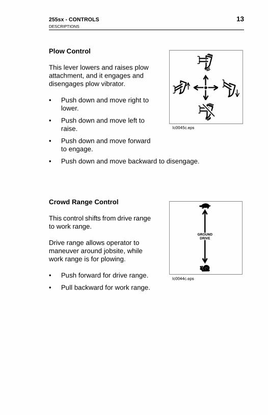
Plow Control
This lever lowers and raises plow attachment, and it engages and disengages plow vibrator.
• Push down and move right to lower.
• Push down and move left to raise.
• Push down and move forward to engage.
• Push down and move backward to disengage.
Crowd Range Control
This control shifts from drive range to work range.
Drive range allows operator to maneuver around jobsite, while work range is for plowing.
• Push forward for drive range.
• Pull backward for work range.
255sx - CONTROLS 13DESCRIPTIONS
Plow Control
This lever lowers and raises plow attachment, and it engages and disengages plow vibrator.
• Push down and move right to lower.
• Push down and move left to raise.
• Push down and move forward to engage.
• Push down and move backward to disengage.
Crowd Range Control
This control shifts from drive range
to work range.Drive range allows operator to maneuver around jobsite, while work range is for plowing.
• Push forward for drive range.
• Pull backward for work range.

14 255sx - CONTROLSDESCRIPTIONS
14 255sx - CONTROLSDESCRIPTIONS
Speed/Direction Control
This lever controls unit speed and direction.
The speed/direction control is spring-centered and will return to neutral when released.
• Push down and move left to travel forward.
• Push down and move right to reverse.
• Return to center (neutral) position to stop.
• Push down and move in the direction of intended travel to turn.
Axle Lock
This control connects left and right ground drive motor systems for positive four-wheel drive.
Axle lock provides superior traction for rough or slippery terrain; however, differential action between left and right drive motors is eliminated.
• Push to lock.
• Pull to release.
Speed
This ledirectio
The spspringneutra
• Putra
• Pure
• Re
• Puof
Axle L
This cogroundpositiv
Axle lotractioterrainbetweeis elim
• Pu
• Pu
/Direction Control
ver controls unit speed and n.
eed/direction control is -centered and will return to l when released.
sh down and move left to vel forward.
sh down and move right to verse.
turn to center (neutral) position to stop.
sh down and move in the direction intended travel to turn.
ock
ntrol connects left and right drive motor systems for e four-wheel drive.
ck provides superior n for rough or slippery ; however, differential action n left and right drive motors
inated.
sh to lock.
ll to release.

255sx - CONTROLS 15DESCRIPTIONS
Plow Swing Lock
This control locks plow in any position.
• Push to lock.
• Pull to release.
Parking Brake
This lever holds unit at rest.
• Push to set.
• Pull to release.
Ignition Switch
This switch starts and stops engine.
• Insert key and turn clockwise to start.
• When engine starts, release key. It will return to on position.
• If engine does not start or is killed, turn to STOP then restart.

16 255sx - CONTROLSDESCRIPTIONS
16 255sx - CONTROLSDESCRIPTIONS
Hourmeter
This gauge records engine operating time and is used to schedule lubrication and maintenance.
Hourmeter runs as long as ignition switch is in the on position.
Voltmeter
This gauge measures voltage in electrical system.
Readings should be between 13-15 volts with engine running. If not, stop engine and determine cause.
Fuel Gauge
This gauge shows level of fuel in tank.
Hourm
This goperatschedumainte
Hourmswitch
Voltm
This gelectric
Readin15 voltstop e
Fuel G
This gtank.
eter
auge records engine ing time and is used to le lubrication and nance.
eter runs as long as ignition is in the on position.
eter
auge measures voltage in al system.
gs should be between 13-s with engine running. If not, ngine and determine cause.
auge
auge shows level of fuel in

255sx - CONTROLS 17DESCRIPTIONS
Choke
This control assists in starting cold engine.
• Pull out before starting engine.
• Push in after engine is running.
255sx - CONTROLS 17DESCRIPTIONS
Choke
This control assists in starting cold engine.
• Pull out before starting engine.
• Push in after engine is running.

18 255sx - CONTROLS 18 255sx - CONTROLS
255sx - SAFETY 19
SAFETY
Follow these guidelines before operating any jobsite equipment:
• Complete proper training and read operator’s manual before using equipment.
• Contact One-Call (888-258-0808) and any utility companies. Have all underground lines and cables located and marked before operating equipment. If you damage a utility, contact utility company.
• Classify jobsite based on its hazards and use correct equipment, safety equipment, and work methods for jobsite.
• Mark jobsite clearly and keep spectators away.
• Wear personal protective equipment.
• Review jobsite hazards, safety and emergency procedures, and individual responsibilities with all personnel before work begins. Safety videos are available from your Ditch Witch dealer.
• Replace missing or damaged safety shields and safety signs.
• Use equipment carefully. Stop operation and investigate anything that does not look or feel right.
• Do not operate unit where flammable gas is present.
• Contact your Ditch Witch dealer if you have any question about operation, maintenance, or equipment use.

20 255sx - SAFETYUNDERGROUND HAZARDS
20 255sx - SAFETYUNDERGROUND HAZARDS
UNDERGROUND HAZARDS
Striking underground hazards can cause explosion, electrocution, fire, and exposure to hazardous materials.
Hazards include:
• Electric cables
• Natural gas lines
• Fiber optic lines
• Water lines
• Sewer lines
• Pipes carrying other chemicals, liquids, or gases
• Storage tanks
UND
Strikinfire, an
Hazard
• El
• Na
• Fib
• W
• Se
• Pi
• St
ERGROUND HAZARDS
g underground hazards can cause explosion, electrocution, d exposure to hazardous materials.
s include:
ectric cables
tural gas lines
er optic lines
ater lines
wer lines
pes carrying other chemicals, liquids, or gases
orage tanks

255sx - SAFETY 21EMERGENCY PROCEDURES
EMERGENCY PROCEDURES
If an Electric Line is Damaged• DO NOT MOVE. Stay where you are and do not touch any
equipment.
• Warn others that an electric line has been hit and that they should stay away.
• Have someone contact electric company.
• Do not return to area until given permission by electric company.
If a Gas Line is Damaged
If you suspect a gas line has been damaged, take the following actions. The order and degree of action will depend on the situation.
• Immediately shut off engine(s), if this can be done safely and quickly.
• Remove any ignition source(s), if this can be done safely and quickly.
• Warn others that a gas line has been cut and that they should leave the area.
• Leave jobsite as quickly as possible.
• Immediately call your local emergency phone number and utility company.
• If jobsite is along street, stop traffic from driving near jobsite.
• Do not return to jobsite until given permission by emergency personnel and utility company.
255sx - SAFETY 21EMERGENCY PROCEDURES
EMERGENCY PROCEDURES
If an Electric Line is Damaged• DO NOT MOVE. Stay where you are and do not touch any
equipment.
• Warn others that an electric line has been hit and that they should stay away.
• Have someone contact electric company.
• Do not return to area until given permission by electric company.
If a Gas Line is Damaged
If you suspect a gas line has been damaged, take the following actions. The order and degree of action will depend on the situation.
• Immediately shut off engine(s), if this can be done safely and
quickly.• Remove any ignition source(s), if this can be done safely and quickly.
• Warn others that a gas line has been cut and that they should leave the area.
• Leave jobsite as quickly as possible.
• Immediately call your local emergency phone number and utility company.
• If jobsite is along street, stop traffic from driving near jobsite.
• Do not return to jobsite until given permission by emergency personnel and utility company.

22 255sx - SAFETYEMERGENCY PROCEDURES
22 255sx - SAFETYEMERGENCY PROCEDURES
If a Fiber Optic Cable is Damaged
Do not look into cut ends of fiber optic or unidentified cable. Vision damage can occur.
If Machine Catches on Fire
Perform emergency shutdown procedure and then take the following actions. The order and degree of action will depend on the situation.
• Immediately move battery disconnect switch (if equipped) to disconnect postition.
• If fire is small and fire extinguisher is available, attempt to extinguish fire.
• If fire cannot be extinguished, leave area as quickly as possible and contact emergency personnel.
If a F
Do notVision
If Ma
Perforfollowithe situ
• Imdis
• If fex
• If fpo
iber Optic Cable is Damaged
look into cut ends of fiber optic or unidentified cable. damage can occur.
chine Catches on Fire
m emergency shutdown procedure and then take the ng actions. The order and degree of action will depend on ation.
mediately move battery disconnect switch (if equipped) to connect postition.
ire is small and fire extinguisher is available, attempt to tinguish fire.
ire cannot be extinguished, leave area as quickly as ssible and contact emergency personnel.

255sx - SAFETY 23SAFETY ALERT CLASSIFICATIONS
SAFETY ALERT CLASSIFICATIONS
These classifications and the icons defined on the following pages work together to alert you to situations which could be harmful to you, jobsite bystanders or your equipment. When you see these words and icons in the book or on the machine, carefully read and follow all instructions. YOUR SAFETY IS AT STAKE.
Watch for the three safety alert levels: DANGER, WARNING and CAUTION. Learn what each level means.
indicates an imminently hazardous situation which, if not avoided, will result in death or serious injury.
indicates a potentially hazardous situation which, if not avoided, could result in death or serious injury.
indicates a potentially hazardous situation which, if not avoided, may result in minor or moderate injury.
Watch for two other words: NOTICE and IMPORTANT.
NOTICE can keep you from doing something that might damage the machine or someone’s property. It can also alert against unsafe practices.
IMPORTANT can help you do a better job or make your job easier in some way.
24 255sx - SAFETYSAFETY ALERTS
24 255sx - SAFETYSAFETY ALERTS
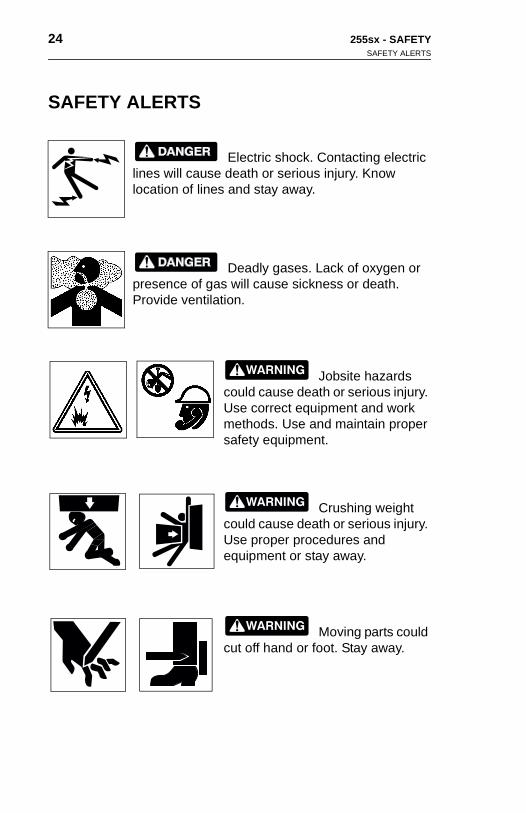
SAFETY ALERTS
Electric shock. Contacting electric lines will cause death or serious injury. Know location of lines and stay away.
Deadly gases. Lack of oxygen or presence of gas will cause sickness or death. Provide ventilation.
Jobsite hazards could cause death or serious injury. Use correct equipment and work methods. Use and maintain proper safety equipment.
Crushing weight could cause death or serious injury. Use proper procedures and equipment or stay away.
Moving parts could cut off hand or foot. Stay away.
SAF
ETY ALERTSElectric shock. Contacting electric lines will cause death or serious injury. Know location of lines and stay away.
Deadly gases. Lack of oxygen or presence of gas will cause sickness or death. Provide ventilation.
Jobsite hazards could cause death or serious injury. Use correct equipment and work methods. Use and maintain proper safety equipment.
Crushing weight could cause death or serious injury. Use proper procedures and equipment or stay away.
Moving parts could cut off hand or foot. Stay away.

255sx - SAFETY 25SAFETY ALERTS
Runaway possible. Machine could run over you or others. Learn how to use all controls. Start and operate only from operator’s position.
Improper control function could cause death or serious injury. If control does not work as described in instructions, stop machine and have it serviced.
Incorrect procedures could result in death, injury, or property damage. Learn to use equipment correctly.
NOTICES:
• Unless otherwise instructed, all service should be performed with engine shut off.
• Refer to engine manufacturer's manual for engine maintenance instructions.

26 255sx - SAFETYSAFETY ALERTS
26 255sx - SAFETYSAFETY ALERTS
Hot parts may cause burns. Do not touch until cool.
Exposure to high noise levels may cause hearing loss. Wear hearing protection.
Hot parts may cause burns. Do not touch until cool.
Exposure to high noise levels may cause hearing loss. Wear hearing protection.

255sx - OPERATION 27INSPECT MACHINE
OPERATION
INSPECT MACHINE
Check the following before each day's work. Refer to LUBRICATION and MAINTENANCE chapters for additional information.
• General appearance.
• Condition of plow blade, drive belts, and air filter.
• Hydraulic oil level, system leaks, and filler/breather assembly.
• Plow vibrator oil level.
• Air filter, hoses, and clamps.
• Fuel lines and fittings for signs of leakage, wear, or other damage.
• Tire pressure. Use reliable tire pressure gauge.
• Engine oil level. Keep oil level at highest line on filler cap/dipstick.
• Fuel level. Fill tank at end of day to reduce condensation.
• Signs are in place and readable.
• Guards and shields are secure and in place.
• Controls in neutral or disengage positions.
• Nuts and bolts are tight. Tighten as specified in torque tables in Parts Manual.
255sx - OPERATION 27INSPECT MACHINE
OPERATION
INSPECT MACHINE
Check the following before each day’s work. Refer to LUBRICATION and MAINTENANCE chapters for additional information.
• General appearance.
• Condition of plow blade, drive belts, and air filter.
• Hydraulic oil level, system leaks, and filler/breather assembly.
• Plow vibrator oil level.
• Air filter, hoses, and clamps.
• Fuel lines and fittings for signs of leakage, wear, or other damage.
• Tire pressure. Use reliable tire pressure gauge.
• Engine oil level. Keep oil level at highest line on filler cap/dipstick.
• Fuel level. Fill tank at end of day to reduce condensation.
• Signs are in place and readable.
• Guards and shields are secure and in place.
• Controls in neutral or disengage positions.
• Nuts and bolts are tight. Tighten as specified in torque tables in Parts Manual.

28 255sx - OPERATIONSTART SYSTEM
28 255sx - OPERATIONSTART SYSTEM
START SYSTEM
Deadly gases. Lack of oxygen or presence of gas will cause sickness or death. Provide ventilation.
Incorrect procedures could result in death, injury, or property damage. Learn to use equipment correctly.
IMPORTANT: Read engine manufacturer’s starting and operating instructions. Follow directions for new engine break-in.
1. Check that all controls are in neutral or disengaged position.
2. Engage parking brake.
3. Open fuel shutoff valve.
4. Move throttle to half open.
5. Insert key and start engine.
IMPORTANT: If engine does not start within 30 seconds, release ignition key. Allow starter to cool before attempting to start again. If engine does not start after three attempts, determine cause.
6. Run engine at half throttle or less for five minutes before operating. After engine has warmed up, check function of all controls.
STA
IMPORinstruc
1. Ch
2. En
3. Op
4. Mo
5. Ins
IMrestade
6. Ruopco
RT SYSTEM
Deadly gases. Lack of oxygen or presence of gas will cause sickness or death. Provide ventilation.
Incorrect procedures could result in death, injury, or property damage. Learn to use equipment correctly.
TANT: Read engine manufacturer’s starting and operating tions. Follow directions for new engine break-in.
eck that all controls are in neutral or disengaged position.
gage parking brake.
en fuel shutoff valve.
ve throttle to half open.
ert key and start engine.
PORTANT: If engine does not start within 30 seconds, lease ignition key. Allow starter to cool before attempting to rt again. If engine does not start after three attempts, termine cause.
n engine at half throttle or less for five minutes before erating. After engine has warmed up, check function of all ntrols.

255sx - OPERATION 29SHUTDOWN
SHUTDOWN
Improper control function could cause death or serious injury. If control does not work as described in instructions, stop machine and have it serviced.
EMERGENCY SHUTDOWN: Turn key switch to STOP.
1. Return all controls to neutral or disengaged position.
2. Lower plow to ground and engage parking brake.
3. Briefly run at half throttle or less to cool engine.
4. Completely close throttle.
5. Place crowd range control into work range.
6. Turn ignition switch to STOP and remove key.
7. Close fuel shutoff valve.

30 255sx - OPERATIONDRIVE
30 255sx - OPERATIONDRIVE
DRIVE
Incorrect procedures could result in death, injury, or property damage. Learn to use equipment correctly.
NOTICE: Drive slowly and cautiously at all times.
Jobsite hazards could cause death or serious injury. Use correct equipment and work methods. Use and maintain proper safety equipment.
1. Check that speed/direction control is in neutral.
2. Start engine and run at low idle.
3. Raise plow attachment.
4. Move crowd range control to drive range.
5. Ensure tires are steered straight or in direction of intended turn.
6. Move throttle lever to half open position.
7. Slowly engage speed/direction control.
8. Adjust engine speed with throttle for desired maximum ground speed.
9. Adjust drive speed with speed/direction control.
10. To stop, move speed/direction control to neutral.
DRIV
1. Ch
2. Sta
3. Ra
4. Mo
5. Entur
6. Mo
7. Sl
8. Adgr
9. Ad
10. To
E
Incorrect procedures could result in death, injury, or property damage. Learn to use equipment correctly.
NOTICE: Drive slowly and cautiously at all times.
Jobsite hazards could cause death or serious injury. Use correct equipment and work methods. Use and maintain proper safety equipment.
eck that speed/direction control is in neutral.
rt engine and run at low idle.
ise plow attachment.
ve crowd range control to drive range.
sure tires are steered straight or in direction of intended n.
ve throttle lever to half open position.
owly engage speed/direction control.
just engine speed with throttle for desired maximum ound speed.
just drive speed with speed/direction control.
stop, move speed/direction control to neutral.
255sx - OPERATION 31PLOW
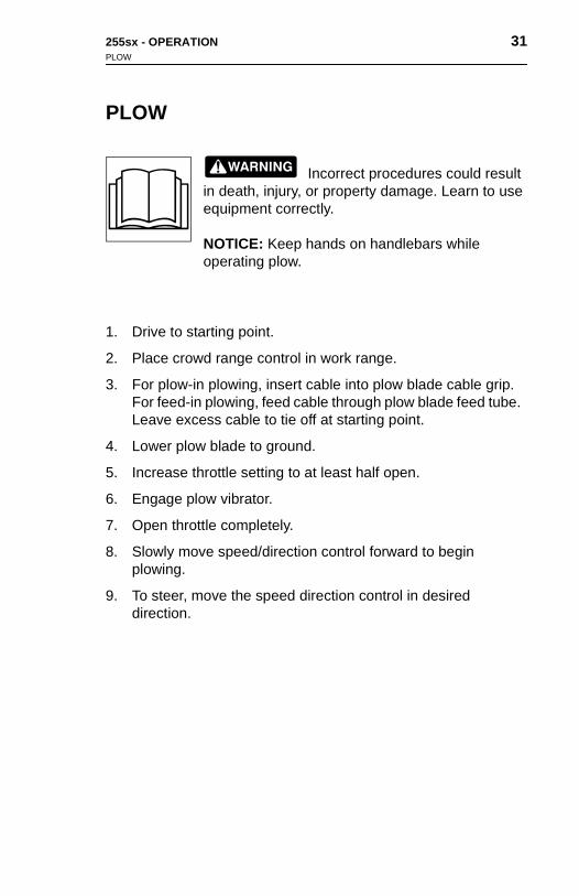
PLOW
Incorrect procedures could result in death, injury, or property damage. Learn to use equipment correctly.
NOTICE: Keep hands on handlebars while operating plow.
1. Drive to starting point.
2. Place crowd range control in work range.
3. For plow-in plowing, insert cable into plow blade cable grip. For feed-in plowing, feed cable through plow blade feed tube. Leave excess cable to tie off at starting point.
4. Lower plow blade to ground.
5. Increase throttle setting to at least half open.
6. Engage plow vibrator.
7. Open throttle completely.
8. Slowly move speed/direction control forward to begin plowing.
9. To steer, move the speed direction control in desired direction.
255sx - OPERATION 31PLOW
PLOW
Incorrect procedures could result in death, injury, or property damage. Learn to use equipment correctly.
NOTICE: Keep hands on handlebars while operating plow.
1. Drive to starting point.
2. Place crowd range control in work range.
3. For plow-in plowing, insert cable into plow blade cable grip. For feed-in plowing, feed cable through plow blade feed tube. Leave excess cable to tie off at starting point.
4. Lower plow blade to ground.
5. Increase throttle setting to at least half open.
6. Engage plow vibrator.
7. Open throttle completely.
8. Slowly move speed/direction control forward to begin plowing.
9. To steer, move the speed direction control in desired direction.

32 255sx - OPERATIONPLOW
32 255sx - OPERATIONPLOW
10. Unlock plow swing before turning.
11. To raise plow at end of job:
• Begin raising plow blade from ground.
• Leave plow vibrator engaged until plow blade is almost at ground level, then disengage vibrator and continue raising.
• In sticky soils or when installing delicate cable, it may be necessary to move the unit forward as plow blade is raised.
• Place plow swing lock in locked position before blade clears ground.
12. Follow shutdown procedure.
13. Remove cable from cable chute and follow blade removal procedure.
10. Un
11. To
•
•
•
•
12. Fo
13. Repr
lock plow swing before turning.
raise plow at end of job:
Begin raising plow blade from ground.
Leave plow vibrator engaged until plow blade is almost at ground level, then disengage vibrator and continue raising.
In sticky soils or when installing delicate cable, it may be necessary to move the unit forward as plow blade is raised.
Place plow swing lock in locked position before blade clears ground.
llow shutdown procedure.
move cable from cable chute and follow blade removal ocedure.

255sx - OPERATION 33ATTACH AND REMOVE BLADE
ATTACH AND REMOVE BLADE
1. Raise plow attachment and shut down engine.
2. Position blade with cutting edge down so pin holes in blade align with those in vibrator trolley.
3. Install upper (rear) blade pin first, then install lower (front) pin.
4. Secure both pins with keeper pins.
5. Restart engine and lower plow attachment to ground.
6. To remove blade, remove keeper pins and pull out two plow blade pins.

34 255sx - OPERATION 34 255sx - OPERATION

255sx - TRANSPORTATION 35LIFT
TRANSPORTATION
LIFT
Crushing weight could cause death or serious injury. Use proper procedures and equipment or stay away.
Procedure
Before lifting, check SPECIFICATIONS chapter. Use a crane capable of supporting the equipment’s size and weight.
Engage barking brake and plow swing lock before lifting.
Lift unit by attaching slings to wheels and to a common member.
255sx - TRANSPORTATION 35LIFT
TRANSPORTATION
LIFT
Crushing weight could cause death or serious injury. Use proper procedures and equipment or stay away.
Procedure
Before lifting, check SPECIFICATIONS chapter. Use a crane
capable of supporting the equipment’s size and weight.Engage barking brake and plow swing lock before lifting.
Lift unit by attaching slings to wheels and to a common member.
36 255sx - TRANSPORTATIONHAUL
36 255sx - TRANSPORTATIONHAUL
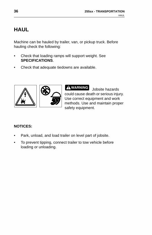
HAUL
Machine can be hauled by trailer, van, or pickup truck. Before hauling check the following:
• Check that loading ramps will support weight. See SPECIFICATIONS.
• Check that adequate tiedowns are available.
Jobsite hazards could cause death or serious injury. Use correct equipment and work methods. Use and maintain proper safety equipment.
NOTICES:
• Park, unload, and load trailer on level part of jobsite.
• To prevent tipping, connect trailer to tow vehicle before loading or unloading.
HAU
Machinhauling
• ChSP
• Ch
NOTIC
• Pa
• Toloa
L
e can be hauled by trailer, van, or pickup truck. Before check the following:
eck that loading ramps will support weight. See ECIFICATIONS.
eck that adequate tiedowns are available.
Jobsite hazards could cause death or serious injury. Use correct equipment and work methods. Use and maintain proper safety equipment.
ES:
rk, unload, and load trailer on level part of jobsite.
prevent tipping, connect trailer to tow vehicle before ding or unloading.

255sx - TRANSPORTATION 37LOAD
LOAD
1. Align machine with ramps or trailer.
2. Start machine following instructions in OPERATION.
3. Move throttle to half open.
EMERGENCY SHUTDOWN: Turn ignition switch to STOP position.
4. Move crowd range control to work position.
5. Slowly guide the machine onto trailer.
6. When tiedown position is reached, move speed/direction control to neutral position.
7. Lower plow blade to trailer bed.
8. Leaving crowd range control in work mode, completely close throttle, turn ignition switch key to STOP, and remove key.
9. Close fuel shutoff valve.
10. Securely chain unit to trailer using tiedown binders.

38 255sx - TRANSPORTATIONUNLOAD
38 255sx - TRANSPORTATIONUNLOAD
UNLOAD
1. Remove tiedowns from machine.
2. Start machine following instructions in OPERATION.
3. Use speed/direction control to slowly back machine off trailer or down ramps.
UNL
1. Re
2. Sta
3. Usor
OAD
move tiedowns from machine.
rt machine following instructions in OPERATION.
e speed/direction control to slowly back machine off trailer down ramps.

255sx - DRILLING ATTACHMENT 39
DRILLING ATTACHMENT
Use Roto Witch attachment to drill under obstructions such as sidewalks and driveways. Roto Witch attachments come in two types: wet bore and dry bore. Wet bore pipe is used for wet or dry drilling; dry bore rod is used for dry drilling only.
Electrical shock. Contacting electrical lines will cause death or serious injury. Know location of lines and stay away.
Turning shaft will kill you or crush arm or leg. Stay away.
NOTICES:
• Keep everyone at least 10 feet (3 m) away from turning drill string. Do not straddle trench or drill string while drilling.
• If swivel malfunctions, material being installed can rotate.
• Keep all persons away from material being installed.
EMERGENCY SHUTDOWN: Turn ignition switch to STOP.
sf1019
sf1016
255sx - DRILLING ATTACHMENT 39
DRILLING ATTACHMENT
Use Roto Witch attachment to drill under obstructions such as sidewalks and driveways. Roto Witch attachments come in two types: wet bore and dry bore. Wet bore pipe is used for wet or dry drilling; dry bore rod is used for dry drilling only.
Electrical shock. Contacting electrical lines will cause death or serious injury. Know location of lines and stay away.
Turning shaft will kill you or crush arm or leg. Stay away.
sf1019
sf1016
NOTICES:
• Keep everyone at least 10 feet (3 m) away from turning drill string. Do not straddle trench or drill string while drilling.
• If swivel malfunctions, material being installed can rotate.
• Keep all persons away from material being installed.
EMERGENCY SHUTDOWN: Turn ignition switch to STOP.

40 255sx - DRILLING ATTACHMENTBORE TYPES
40 255sx - DRILLING ATTACHMENTBORE TYPES
BORE TYPES
Wet bore Roto Witch attachments (A) use hollow drill pipe screwed together using pipe wrenches.
Dry bore Roto Witch attachments (B) use solid stem rods attached with slip-latch couplers.
NOTICE: Do not use bolts or pins to replace broken spring-loaded tabs. Replace with new tabs or drill rod.
om1208x.pcx
BOR
Wet boscrewe
Dry boattach
NOTICspring
om1208x
E TYPES
re Roto Witch attachments (A) use hollow drill pipe d together using pipe wrenches.
re Roto Witch attachments (B) use solid stem rods ed with slip-latch couplers.
E: Do not use bolts or pins to replace broken -loaded tabs. Replace with new tabs or drill rod.
.pcx
255sx - DRILLING ATTACHMENT 41SETUP
SETUP
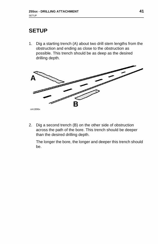
1. Dig a starting trench (A) about two drill stem lengths from the obstruction and ending as close to the obstruction as possible. This trench should be as deep as the desired drilling depth.
2. Dig a second trench (B) on the other side of obstruction across the path of the bore. This trench should be deeper than the desired drilling depth.
The longer the bore, the longer and deeper this trench should be.
om1896x
255sx - DRILLING ATTACHMENT 41SETUP
SETUP
1. Dig a starting trench (A) about two drill stem lengths from the obstruction and ending as close to the obstruction as possible. This trench should be as deep as the desired drilling depth.
2. Dig a second trench (B) on the other side of obstruction across the path of the bore. This trench should be deeper
om1896x
than the desired drilling depth.
The longer the bore, the longer and deeper this trench should be.

42 255sx - DRILLING ATTACHMENTSETUP
42 255sx - DRILLING ATTACHMENTSETUP
IMPORTANT: If mechanical guide is necessary to control drill rod in starting trench, guide rods or stem guides are recommended.
3. Connect one or two lengths of drill string and install drill bit.
4. Position drilling attachment in line with intended bore and slowly move up to drill string.
5. Shut down engine and attach end of string to drilling attachment quick-disconnect yoke.
IMPORin star
3. Costr
4. Powimo
5. Shof qu
TANT: If mechanical guide is necessary to control drill rod ting trench, guide rods or stem guides are recommended.
nnect one or two lengths of drill ing and install drill bit.
sition drilling attachment in line th intended bore and slowly ve up to drill string.
ut down engine and attach end string to drilling attachment ick-disconnect yoke.

255sx - DRILLING ATTACHMENT 43DRILLING
DRILLING
NOTICE: Push rod or pipe slowly. Forcing can bend string. Bent rod or pipe should not be used.
1. When setup is complete, check that gearbox control is in low.
2. Start engine and use throttle to control drilling attachment rotation speed.
Turning shaft will kill you or crush arm or leg. Stay away.
Improper control function could cause death or serious injury. If control does not work as described in instructions, stop machine and have it serviced.
NOTICE: Do not alter controls. Improper control function can cause serious injury. If releasing control does not stop turning shaft, turn off power supply, stop drilling, and have unit repaired.
3. Start drilling in clockwise direction by pushing top of Roto Witch control button.
IMPORTANT: If using wet bore pipe, do not rotate counterclockwise, or pipe will unscrew and come apart in ground.
sf1016
sf1020
255sx - DRILLING ATTACHMENT 43DRILLING
DRILLING
NOTICE: Push rod or pipe slowly. Forcing can bend string. Bent rod or pipe should not be used.
1. When setup is complete, check that gearbox control is in low.
2. Start engine and use throttle to control drilling attachment rotation speed.
Turning shaft will kill you or crush arm or leg. Stay away.
Improper control function could cause death or serious injury. If control does not work as described in instructions, stop machine
sf1016
and have it serviced.
NOTICE: Do not alter controls. Improper control function can cause serious injury. If releasing control does not stop turning shaft, turn off power supply, stop drilling, and have unit repaired.
3. Start drilling in clockwise direction by pushing top of Roto Witch control button.
IMPORTANT: If using wet bore pipe, do not rotate counterclockwise, or pipe will unscrew and come apart in ground.
sf1020

44 255sx - DRILLING ATTACHMENTDRILLING
44 255sx - DRILLING ATTACHMENTDRILLING
4. Start bore by moving attachment speed/direction control forward. Start bore very slowly to maintain grade. Increase speed after bore is underway.
5. To add to existing drill string:
• Stop tractor and shut off engine.
• Disconnect drill string from drilling attachment.
• Move machine away from bore.
• Attach new pipe or rod to drill string.
• Repeat to complete bore.
4. Staforsp
5. To
•
•
•
•
•
rt bore by moving attachment speed/direction control ward. Start bore very slowly to maintain grade. Increase eed after bore is underway.
add to existing drill string:
Stop tractor and shut off engine.
Disconnect drill string from drilling attachment.
Move machine away from bore.
Attach new pipe or rod to drill string.
Repeat to complete bore.

255sx - DRILLING ATTACHMENT 45BACKREAM
BACKREAM
Backreaming enlarges the bore.
Do not try to increase bore size too much at one time. Several passes using successively larger reamers will save wear on machine.
1. Shut down tractor and attach backreamer.
2. Start tractor.
3. Turn drilling attachment clockwise and pull speed/direction control to move backreamer through bore.
JOINT DISASSEMBLY
To separate screw-on drill pipe sections and end attachment:
1. Loosen joints with pipe wrenches.
2. Clean and oil threaded joints after disassembly.
3. Cover exposed threads to prevent damage.
To separate slip-latch couplers:
1. Using special tool, press tab through hole in joint while pulling stems apart.
2. Clean and oil exposed joints to prevent damage.

46 255sx - DRILLING ATTACHMENTOPTIONAL EQUIPMENT
46 255sx - DRILLING ATTACHMENTOPTIONAL EQUIPMENT
OPTIONAL EQUIPMENT
Drill Pipe and Rod
Bent or damaged pipe and rod might break when being pushed. Replacement drill pipe, rod, and connectors are available through your Ditch Witch dealer.
Bits and Backreamers
Bits and backreamers are available in a variety of sizes and types to match jobsite needs. Contact your Ditch Witch dealer for more information.
OPT
Drill P
Bent oReplacyour D
Bits a
Bits anto matinform
IONAL EQUIPMENT
ipe and Rod
r damaged pipe and rod might break when being pushed. ement drill pipe, rod, and connectors are available through itch Witch dealer.
nd Backreamers
d backreamers are available in a variety of sizes and types ch jobsite needs. Contact your Ditch Witch dealer for more ation.
255sx - LUBRICATION 47
LUBRICATION
Proper lubrication and maintenance protects Ditch Witch equipment from damage and failure. In extreme conditions, lubricate more frequently.
Use only recommended lubricants. Fill to capacities listed in SPECIFICATIONS chapter.
Incorrect procedures could result in death, injury, or property damage. Learn to use equipment correctly.
NOTICES:
• Unless otherwise instructed, all service should be performed with engine off.
• Refer to engine manufacturer’s manual for engine maintenance instructions.
Recommended Lubricants
GEO Gasoline engine oil (see oil temperature chart for appropriate SAE weight) meeting API engine service classification SD
MPG Multipurpose grease lubricant
EO Engine oil of the appropriate SAE weight listed under GEO (API class SD). EO is not for engine applications
THF Tractor hydraulic fluid, similar to Phillips 66 HG, Mobilfluid 423, Chevron Tractor Hydraulic Fluid, Texaco TDH Oil, or equivalent
10W40 Engine oil, SAE 10W40, meeting API service classification S/CC
255sx - LUBRICATION 47
LUBRICATION
Proper lubrication and maintenance protects Ditch Witch equipment from damage and failure. In extreme conditions, lubricate more frequently.
Use only recommended lubricants. Fill to capacities listed in SPECIFICATIONS chapter.
Incorrect procedures could result
Recommended Lubricants
GEO Gasoline engine oil (see oil temperature chart for appropriate SAE weight) meeting API engine service classification SD
MPG Multipurpose grease lubricant
EO Engine oil of the appropriate SAE weight listed under GEO (API class SD). EO is not for engine applications
THF Tractor hydraulic fluid, similar to Phillips 66 HG, Mobilfluid 423, Chevron Tractor Hydraulic Fluid, Texaco TDH Oil, or equivalent
10W40 Engine oil, SAE 10W40, meeting API service classification S/CC
in death, injury, or property damage. Learn to use equipment correctly.
NOTICES:
• Unless otherwise instructed, all service should be performed with engine off.
• Refer to engine manufacturer’s manual for engine maintenance instructions.

48 255sx - LUBRICATIONOVERVIEW
48 255sx - LUBRICATIONOVERVIEW
OVERVIEW
Interval Task Ref. Lubricant
10 hours Check hydraulic oil 2 THF
Check engine oil 1 GEO
Check vibrator oil 4 10W40
50 hours Change engine oil 1 GEO
Lube steering knuckle 7 MPG
Lube spindle bearing 6 MPG
150 hours Change hydraulic oil filter 3
300 hours Change hydraulic oil 2 THF
Change vibrator oil 4 10W40
As needed Lube drive chains 5 EO
Lube drilling attachment cross & bearing 8 MPG
1 2 3
5678
4
Om0209c.eps
OVE
Interva
10 hou
50 hou
150 ho
300 ho
As nee
RVIEW
l Task Ref. Lubricant
rs Check hydraulic oil 2 THF
Check engine oil 1 GEO
Check vibrator oil 4 10W40
rs Change engine oil 1 GEO
Lube steering knuckle 7 MPG
1 2 3
5678
4
Om0209c.eps
Lube spindle bearing 6 MPG
urs Change hydraulic oil filter 3
urs Change hydraulic oil 2 THF
Change vibrator oil 4 10W40
ded Lube drive chains 5 EO
Lube drilling attachment cross & bearing 8 MPG
255sx - LUBRICATION 49ENGINE OIL SYSTEM
ENGINE OIL SYSTEM
Engine Oil
Check
Check engine oil at dipstick every 10 hours. Maintain oil at FULL mark on dipstick.
Change
Change engine oil after first 25 hours and every 50 hours thereafter. Drain plug is located under front-right corner of machine. Fill crankcase through oil fill; refill capacity with filter change is 1.5 qt (1.4 L).
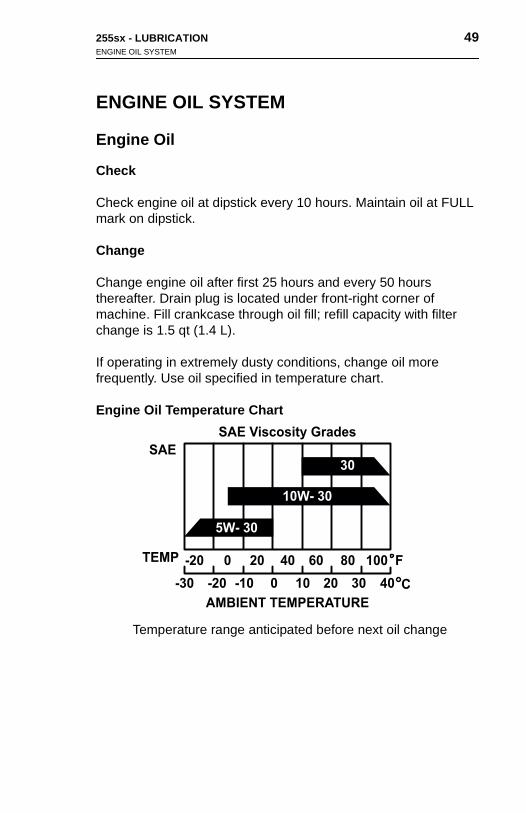
If operating in extremely dusty conditions, change oil more frequently. Use oil specified in temperature chart.
Engine Oil Temperature Chart
5W- 30
10W- 30
30
F
C
-20 0 20 40 60 80 100
-20-30 -10 0 10 20 30 40
SAE Viscosity Grades
SAE
TEMP
AMBIENT TEMPERATURE
Temperature range anticipated before next oil change
255sx - LUBRICATION 49ENGINE OIL SYSTEM
ENGINE OIL SYSTEM
Engine Oil
Check
Check engine oil at dipstick every 10 hours. Maintain oil at FULL mark on dipstick.
Change
Change engine oil after first 25 hours and every 50 hours thereafter. Drain plug is located under front-right corner of machine. Fill crankcase through oil fill; refill capacity with filter change is 1.5 qt (1.4 L).
If operating in extremely dusty conditions, change oil more frequently. Use oil specified in temperature chart.
Engine Oil Temperature Chart
SAE Viscosity Grades
5W- 30
10W- 30
30
F
C
-20 0 20 40 60 80 100
-20-30 -10 0 10 20 30 40
SAE
TEMP
AMBIENT TEMPERATURE
Temperature range anticipated before next oil change
50 255sx - LUBRICATIONHYDRAULIC SYSTEM
50 255sx - LUBRICATIONHYDRAULIC SYSTEM
Engine Oil Filter
Change engine oil filter after first 25 hours and every 100 hours thereafter. Filter is located on right side of engine and may be reached by removing lower grille panel.
If operating in extremely dusty conditions, change filter more frequently. See Parts Manual for replacement filter.
HYDRAULIC SYSTEM
Hydraulic Oil
Check
Check hydraulic oil level daily. Maintain THF at bottom of filler screen.
Change
Change hydraulic oil every 300 hours. Drain plug is located below tank on right side of machine. Refill to bottom of filter screen with THF; tank capacity is 10.5 gal (39.7 L).
Hydraulic Oil Filter
Change hydraulic oil filter after first 25 hours and every 150 hours thereafter. Filter is located behind access door at machine’s right-rear corner. See Parts Manual for replacement filter.
Engin
Changthereareache
If operfreque
HYD
Hydr
Check
Checkscreen
Chang
Changtank oTHF; t
Hydr
Changtherearear co
e Oil Filter
e engine oil filter after first 25 hours and every 100 hours fter. Filter is located on right side of engine and may be d by removing lower grille panel.
ating in extremely dusty conditions, change filter more ntly. See Parts Manual for replacement filter.
RAULIC SYSTEM
aulic Oil
hydraulic oil level daily. Maintain THF at bottom of filler .
e
e hydraulic oil every 300 hours. Drain plug is located below n right side of machine. Refill to bottom of filter screen with ank capacity is 10.5 gal (39.7 L).
aulic Oil Filter
e hydraulic oil filter after first 25 hours and every 150 hours fter. Filter is located behind access door at machine’s right-rner. See Parts Manual for replacement filter.

255sx - LUBRICATION 51GENERAL
GENERAL
Steering Knuckle
Lubricate front wheel steering knuckles with MPG every 50 hours.
Spindle Bearing
Lubricate front wheel spindle bearings with MPG every 50 hours.
Drive Chain
Lubricate drive chains with EO as needed.
255sx - LUBRICATION 51GENERAL
GENERAL
Steering Knuckle
Lubricate front wheel steering knuckles with MPG every 50 hours.
Spindle Bearing
Lubricate front wheel spindle bearings with MPG every 50 hours.
Drive Chain
Lubricate drive chains with EO as needed.

52 255sx - LUBRICATIONPLOW
52 255sx - LUBRICATIONPLOW
PLOW
Vibrator Oil
Check
Check vibrator oil level in sight gauge on gear cover every 10 hours. Maintain 10W40 in sight gauge when vibrator is level. Do not overfill.
Change
Change oil in vibrator gear cover every 300 hours. Use 10W40 and fill to sight gauge. Tank holds 8 oz (227 g). Add 1 oz (28 g) 10W40 to each of the two shaker box cylinders.
DRILLING ATTACHMENT
Lubricate drilling attachment cross & bearing with MPG as needed.
PLO
Vibra
Check
Checkhours.not ov
Chang
Changand fill10W40
DRIL
Lubricneede
W
tor Oil
vibrator oil level in sight gauge on gear cover every 10 Maintain 10W40 in sight gauge when vibrator is level. Do erfill.
e
e oil in vibrator gear cover every 300 hours. Use 10W40 to sight gauge. Tank holds 8 oz (227 g). Add 1 oz (28 g) to each of the two shaker box cylinders.
LING ATTACHMENT
ate drilling attachment cross & bearing with MPG as d.

255sx - MAINTENANCE 53
MAINTENANCE
Proper lubrication and maintenance protects Ditch Witch equipment from damage and failure. In extreme conditions, lubricate more frequently.
Incorrect procedures could result in death, injury, or property damage. Learn to use equipment correctly.
NOTICES:
• Unless otherwise instructed, all service should be performed with engine shut off.
• Refer to engine manufacturer’s manual for engine maintenance instructions.
54 255sx - MAINTENANCEOVERVIEW
54 255sx - MAINTENANCEOVERVIEW
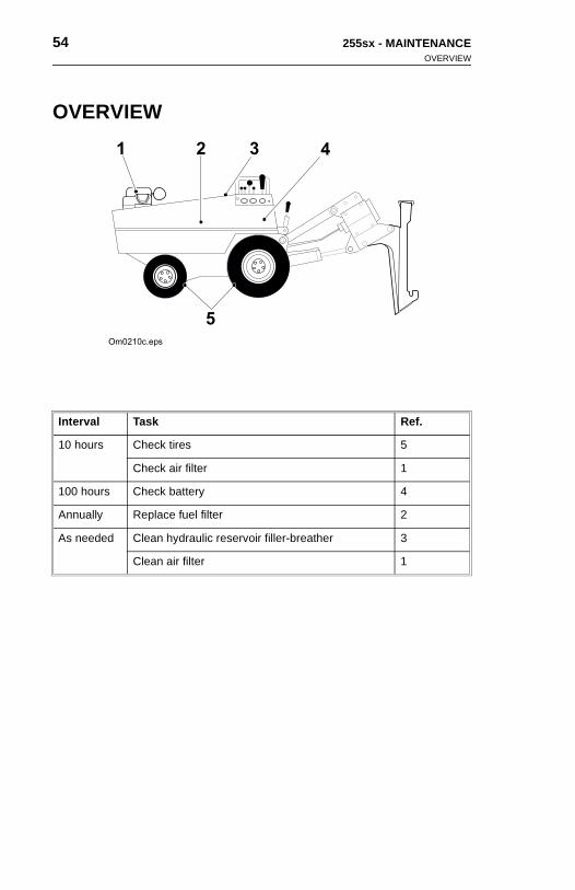
OVERVIEW
Interval Task Ref.
10 hours Check tires 5
Check air filter 1
100 hours Check battery 4
Annually Replace fuel filter 2
As needed Clean hydraulic reservoir filler-breather 3
Clean air filter 1
1 2 3
5
4
Om0210c.eps
OVE
Interva
10 hou
100 ho
Annua
As nee
RVIEW
l Task Ref.
rs Check tires 5
Check air filter 1
urs Check battery 4
lly Replace fuel filter 2
1 2 3
5
4
Om0210c.eps
ded Clean hydraulic reservoir filler-breather 3
Clean air filter 1
255sx - MAINTENANCE 55Engine Components
Engine Components
Air Filter
Check
Check air filter every 10 hours. Clean or replace filter elements as needed. Replace more often if operating in extremely dusty conditions. See Parts Manual for replacement filter.
Procedure1. Remove air cleaner cover.
2. Remove and inspect foam and paper filter elements.
3. Clean or replace elements if they are dirty or damaged.
• Clean paper element by tapping several times on hard surface or blowing compressed air through element from the bottom.
• Clean foam element in warm, soapy water and allow to dry thoroughly.
4. Wipe dirt from insides of air cleaner cover and body with a moist rag.
5. Install both elements into air cleaner case.
IMPORTANT: Ensure that seal lip is not folded over.
6. Install cover and latch tabs securely.

56 255sx - MAINTENANCEHydraulics
56 255sx - MAINTENANCEHydraulics
Air Cleaner System
Visually inspect outside of air cleaner system for loose or damaged parts every 8 hours.
Fuel Filter
Replace fuel filter annually. If unit normally is refueled from cans, replace more often. See Parts Manual for correct replacement.
Hydraulics
Hydraulic Filler/Breather
Check
Check cap periodically and replace if necessary.
Clean
Clean excess dust from hydraulic filler/breather cap by washing in solvent. If filler screen becomes clogged, remove and flush with solvent.
Air C
Visualdamag
Fuel
Replacreplac
Hydr
Hydr
Check
Check
Clean
Clean solvensolven
leaner System
ly inspect outside of air cleaner system for loose or ed parts every 8 hours.
Filter
e fuel filter annually. If unit normally is refueled from cans, e more often. See Parts Manual for correct replacement.
aulics
aulic Filler/Breather
cap periodically and replace if necessary.
excess dust from hydraulic filler/breather cap by washing in t. If filler screen becomes clogged, remove and flush with t.

255sx - MAINTENANCE 57Electrical
Electrical
Battery
Check
Check electrolyte level in battery every 100 hours. Battery is located behind access panel at rear of machine. Add distilled water to keep level above plates. Do not overfill.
Clean
Keep battery clean and free of corrosion. Apply coat of grease to cable clamps after cleaning.
Charge
In cold weather, battery starting ability drops. Closely watch voltmeter for signs of discharge.
If adding water in freezing weather, immediately charge battery to mix water and electrolyte. If battery will not hold charge, see Parts Manual for replacement.
255sx - MAINTENANCE 57Electrical
Electrical
Battery
Check
Check electrolyte level in battery every 100 hours. Battery is located behind access panel at rear of machine. Add distilled water to keep level above plates. Do not overfill.
Clean
Keep battery clean and free of corrosion. Apply coat of grease to cable clamps after cleaning.
Charge
In cold weather, battery starting ability drops. Closely watch voltmeter for signs of discharge.
If adding water in freezing weather, immediately charge battery to
mix water and electrolyte. If battery will not hold charge, see Parts Manual for replacement.
58 255sx - MAINTENANCEPower Train
58 255sx - MAINTENANCEPower Train
Power Train
Tires
Check tires every 10 hours for proper condition and inflation. Use an accurate gauge to ensure correct pressure is maintained.
• Correct pressure for 16 x 6.50-8 front tires is 20 psi (1 bar).
• Correct pressure for 23 x 10.50-12 rear tires is 28 psi (2 bar).
Drive Chain
Adjust drive chains as needed.
To adjust:
1. Use lifting device to raise either side of machine, then block with adequate jackstands.
2. Remove rear tire and wheel assembly to gain access to rear drive chain idler.
IMPORTANT: It is not necessary to remove the front tire and wheel assembly to gain access to the front drive chain idler.
3. Loosen the drive chain idler bolts. Insert a 1/2 inch (13 mm) drive breaker bar into the square hole of the idler and press down firmly on bar to tighten the idler on the drive chain.
4. Securely tighten idler bolts while maintaining downward pressure on the breaker bar.
5. Repeat procedure on opposite side of machine.
Pow
Tires
Checkan acc
• Co(1
• Co
Drive
Adjust
To adj
1. Uswi
2. Redri
IMwh
3. Lodrdo
4. Sepr
5. Re
er Train
tires every 10 hours for proper condition and inflation. Use urate gauge to ensure correct pressure is maintained.
rrect pressure for 16 x 6.50-8 front tires is 20 psi bar).
rrect pressure for 23 x 10.50-12 rear tires is 28 psi (2 bar).
Chain
drive chains as needed.
ust:
e lifting device to raise either side of machine, then block th adequate jackstands.
move rear tire and wheel assembly to gain access to rear ve chain idler.
PORTANT: It is not necessary to remove the front tire and
eel assembly to gain access to the front drive chain idler.osen the drive chain idler bolts. Insert a 1/2 inch (13 mm) ive breaker bar into the square hole of the idler and press wn firmly on bar to tighten the idler on the drive chain.
curely tighten idler bolts while maintaining downward essure on the breaker bar.
peat procedure on opposite side of machine.

255sx - MAINTENANCE 59Plow Attachment
Plow Attachment
Feed Tube
Clean feed tube on plow blades after each use.
255sx - MAINTENANCE 59Plow Attachment
Plow Attachment
Feed Tube
Clean feed tube on plow blades after each use.

60 255sx - MAINTENANCE 60 255sx - MAINTENANCE

255sx - SPECIFICATIONS 61
SPECIFICATIONS
Dimensions U.S. Metric
A Maximum cover depth 13.5 in 343 mm
Maximum penetration depth* 16.2 in 413 mm
A3 Angle of approach:
with reel carrier 41° 41°
without reel carrier 53° 53°
with 25 in (612 mm) reel 28° 28°
A3’ Angle of departure:
with 12 in (305 mm) blade 19° 19°
without blade 40° 40°
H2 Operating/transport height 46 in 1.2 m
J Blade ground clearance 15.4 in 394 mm
H2
A2
A3’
A
J
L2’
L2
A3
L4 W
4
W1
Om0033c.eps
255sx - SPECIFICATIONS 61
SPECIFICATIONS
Dimensions U.S. Metric
A Maximum cover depth 13.5 in 343 mm
H2
A2
A3’
A
J
L2’
L2
A3
L4 W
4
W1
Om0033c.eps
Maximum penetration depth* 16.2 in 413 mm
A3 Angle of approach:
with reel carrier 41° 41°
without reel carrier 53° 53°
with 25 in (612 mm) reel 28° 28°
A3’ Angle of departure:
with 12 in (305 mm) blade 19° 19°
without blade 40° 40°
H2 Operating/transport height 46 in 1.2 m
J Blade ground clearance 15.4 in 394 mm

62 255sx - SPECIFICATIONS 62 255sx - SPECIFICATIONS
L2 Length plowing, without reel carrier 100.5 in 2.6 m
L2’ Length transport, without reel carrier
108.5 in 2.8 m
L4 Wheelbase 34 in 864 mm
W1 Width transport:
maximum 35.8 in 909 mm
minimum 31.5 in 800 mm
W4 Thread front 25 in 635 mm
Rear, STD 25.8 in 655 mm
Rear, OPT 21.5 in 546 mm
Width plow unit 17.5 in 444 mm
Centerline plow in outside edge machine, blade centered:
STD 18 in 457 mm
OPT 15.75 in 400 mm
Note: Dimensions are based on unit equipped with 12 in (305 mm) plow blade. For empty reel carrier, add 12 in (305 mm) to overall lengths
*Suggested maximum blade length. Actual plow blade length will be determined by job requirements and soil conditions
Operational U.S. Metric
Vehicle speeds at 3400 rpm
Maximum transit forward 215 fpm 65.5 mpm
Maximum crowd forward 83 fpm 25.5 mpm
Maximum transit reverse 215 fpm 65.5 mpm
Maximum crowd reverse 83 fpm 25.5 mpm
Nominal plow-in depth 6-12 in 152-305 mm
Maximum bullet diameter, pull blade 3 in 76 mm
Inside diameter feed tube, feed blade 1 in 25 mm
Vehicle clearance, circle, wall-to-wall (SAE), axle locked, drive
26 ft 7.9 m
L2
L2’
L4
W1
W4
Note: Dblade.
*Suggedeterm
Opera
Vehicle
Maxim
Maxim
Maxim
Maxim
Nomin
Maxim
Inside
Vehicle(SAE),
Length plowing, without reel carrier 100.5 in 2.6 m
Length transport, without reel carrier
108.5 in 2.8 m
Wheelbase 34 in 864 mm
Width transport:
maximum 35.8 in 909 mm
minimum 31.5 in 800 mm
Thread front 25 in 635 mm
Rear, STD 25.8 in 655 mm
Rear, OPT 21.5 in 546 mm
Width plow unit 17.5 in 444 mm
Centerline plow in outside edge machine, blade centered:
STD 18 in 457 mm
OPT 15.75 in 400 mm
imensions are based on unit equipped with 12 in (305 mm) plow For empty reel carrier, add 12 in (305 mm) to overall lengths
sted maximum blade length. Actual plow blade length will be
ined by job requirements and soil conditionstional U.S. Metric
speeds at 3400 rpm
um transit forward 215 fpm 65.5 mpm
um crowd forward 83 fpm 25.5 mpm
um transit reverse 215 fpm 65.5 mpm
um crowd reverse 83 fpm 25.5 mpm
al plow-in depth 6-12 in 152-305 mm
um bullet diameter, pull blade 3 in 76 mm
diameter feed tube, feed blade 1 in 25 mm
clearance, circle, wall-to-wall axle locked, drive
26 ft 7.9 m

255sx - SPECIFICATIONS 63
Axle unlocked, drive 16.5 5 m
Operating weight 1650 lb 748 kg
Operator orientation: Facing front of vehicle in full view of all operations
Power Options U.S. Metric
Honda V-twin gasoline engine
Cooling medium: air
Number of cylinders: two
Displacement 40.9 in3 670 cm3
Bore 3 in 77 mm
Stroke 2.8 in 72 mm
Engine manufacturer’s gross power rating at 3600 rpm
24 hp 18 kW
Maximum governed speed as installed (no load)*
3600 rpm 3600 rpm
Power Train U.S. Metric
Transmission: Hydrostatic drive, infinitely variable from zero to maximum, lever operated speed and direction controls
Brake: Direction control brakes machine hydraulically when moved to neutral position
Parking brake: Disc type, hand operated
Tires, load rating at recommended pressure at 10 mph (16 kph)
16 x 6.50-8, front 620 lb 281 kg
@28 psi @ 2 bar
23 x 10.50-12 1340 lb 608 kg
@20 psi @ 1 bar
Hydraulic System U.S. Metric
Pump capacity at 3200 rpm relief valve setting
2000 psi (138 bar) drive range, bore motor
Plow vibrator (SEC #1) 12.5 gpm 47.3 Lmin
255sx - SPECIFICATIONS 63
Axle unlocked, drive 16.5 5 m
Operating weight 1650 lb 748 kg
Operator orientation: Facing front of vehicle in full view of all operations
Power Options U.S. Metric
Honda V-twin gasoline engine
Cooling medium: air
Number of cylinders: two
Displacement 40.9 in3 670 cm3
Bore 3 in 77 mm
Stroke 2.8 in 72 mm
Engine manufacturer’s gross power rating at 3600 rpm
24 hp 18 kW
Maximum governed speed as installed (no load)*
3600 rpm 3600 rpm
Power Train U.S. Metric
Transmission: Hydrostatic drive, infinitely variable from zero to
maximum, lever operated speed and direction controlsBrake: Direction control brakes machine hydraulically when moved to neutral position
Parking brake: Disc type, hand operated
Tires, load rating at recommended pressure at 10 mph (16 kph)
16 x 6.50-8, front 620 lb 281 kg
@28 psi @ 2 bar
23 x 10.50-12 1340 lb 608 kg
@20 psi @ 1 bar
Hydraulic System U.S. Metric
Pump capacity at 3200 rpm relief valve setting
2000 psi (138 bar) drive range, bore motor
Plow vibrator (SEC #1) 12.5 gpm 47.3 Lmin

64 255sx - SPECIFICATIONS 64 255sx - SPECIFICATIONS
Crowd range (SEC #2) 6.7 gpm 25.4 Lmin
Plow lift and steer (SEC #3) 3.6 gpm 13.6 Lmin
Hydraulic motor, ground drive (each)
Torque at 2250 psi (155 bar) and 3.3 gpm (12.5 Lmin)
7353 in•lb 831 N•m
Speed at 2250 psi (155 bar) and 3.3 gpm (12.5 Lmin)
41 rpm 41 rpm
Displacement/rev 24 in3 393.3 cm3
Bidirectional
Hydraulic motor, vibrator
Torque at 2,000 psi (138 bar) and 12.5 gpm (47.3 Lmin)
399 in•lb 45 N•m
Speed at 2,000 psi (138 bar) and 12.5 gpm (47.3 Lmin)
1,560 rpm 1,560 rpm
Displacement/rev 1.48 in3 24.25 cm3
Hydraulic motor, boring
Torque at 2000 psi (138 bar) and 12.5 gpm (47.3 Lmin)
5140 in•lb 581 N•m
Speed at 2000 psi (138) and 12.5 gpm (47.3 Lmin)
139 rpm 139 rpm
Displacement/rev 18.7 in3 306.4 cm3
Filtration:
Suction: Strainer with bypass 100 mesh
Return: Filter with bypass 10 micron nominal
Hydraulic cylinders:
Function: Steering, plow lift
Type: Double acting
Crowd
Plow li
Hydrau
Torque
Speed
Displa
Bidirec
Hydrau
Torque
Speed
Displa
Hydrau
Torque
Speed
Displa
Filtratio
Hydrau
range (SEC #2) 6.7 gpm 25.4 Lmin
ft and steer (SEC #3) 3.6 gpm 13.6 Lmin
lic motor, ground drive (each)
at 2250 psi (155 bar) and 3.3 gpm (12.5 Lmin)
7353 in•lb 831 N•m
at 2250 psi (155 bar) and 3.3 gpm (12.5 Lmin)
41 rpm 41 rpm
cement/rev 24 in3 393.3 cm3
tional
lic motor, vibrator
at 2,000 psi (138 bar) and 12.5 gpm (47.3 Lmin)
399 in•lb 45 N•m
at 2,000 psi (138 bar) and 12.5 gpm (47.3 Lmin)
1,560 rpm 1,560 rpm
cement/rev 1.48 in3 24.25 cm3
lic motor, boring
at 2000 psi (138 bar) and 12.5 gpm (47.3 Lmin)
5140 in•lb 581 N•m
at 2000 psi (138) and 12.5 gpm (47.3 Lmin)
139 rpm 139 rpm
cement/rev 18.7 in3 306.4 cm3
n:
Suction: Strainer with bypass 100 mesh
Return: Filter with bypass 10 micron nominal
lic cylinders:
Function: Steering, plow lift
Type: Double acting

255sx - SPECIFICATIONS 65
Specifications are called out according to SAE recommended practices. Specifications are general and subject to change without notice. If exact measurements are required, equipment should be weighted and measured. Due to selected options, delivered equipment may not necessarily match that shown.
Steering U.S. Metric
Power, front wheels, lever controlled
Fluid Capacities U.S. Metric
Fuel tank 9 gal 34 L
Engine lubrication oil, incl. filter 1.5 qt 1.4 L
Vibrator oil 24 oz 710 mL
Hydraulic oil, system 13 gal 49.2 L
Tank 10.5 gal 39.7 L
Battery U.S. Metric
BCI Group U1-SAE res. capacity 35 minutes SAE cold crank at 0°F (-18°C) 255 amps (P/N 215-252)
Optional Equipment U.S. Metric
Reel carrier: Maximum reel weight 100 lb (45.4 kg), maximum reel diameter 25 in (635 mm)
Drilling attachment
255sx - SPECIFICATIONS 65
Steering U.S. Metric
Power, front wheels, lever controlled
Fluid Capacities U.S. Metric
Fuel tank 9 gal 34 L
Engine lubrication oil, incl. filter 1.5 qt 1.4 L
Vibrator oil 24 oz 710 mL
Hydraulic oil, system 13 gal 49.2 L
Tank 10.5 gal 39.7 L
Battery U.S. Metric
BCI Group U1-SAE res. capacity 35 minutes SAE cold crank at 0°F (-18°C) 255 amps (P/N 215-252)
Optional Equipment U.S. Metric
Reel carrier: Maximum reel weight 100 lb (45.4 kg), maximum reel diameter 25 in (635 mm)
Drilling attachment
Specifications are called out according to SAE recommended practices. Specifications are general and subject to change without notice. If exact measurements are required, equipment should be weighted and measured. Due to selected options, delivered equipment may not necessarily match that shown.

66 255sx - SPECIFICATIONS 66 255sx - SPECIFICATIONS

255sx - WARRANTY 67
WARRANTY
Ditch Witch Equipment and Replacement Parts North American*
Limited Warranty Policy
Major Component Limited WarrantyMajor components are warranted for a period of 1000 hours of use or one year, whichever occurs first, beginning on date of delivery of any such new product. The Major Component Limited Warranty covers only Major Components listed under Major Component Limited Warranty that are manufactured and distributed by The Charles Machine Works, Inc. (“CMW”). Replacement parts and other serial numbered products (“Products”) that are not listed under Major Component Limited Warranty, and non-major components are covered under Product Limited Warranty.
Major Components are defined as:
• Frames.
• Differentials and parts contained within.
• Mechanical transmissions.
• Drive gearboxes and parts contained within.
• Hydraulic, hydrostatic, and fluid pumps, motors and components that control or
protect pumps and motors.
• Auxiliary hydraulic control valves and electrical components used for controlling
hydraulic components.
• Hydraulic cylinders and components excluding repair kits.
• Batteries, alternators, instruments, gauges, and protection components for
electrical systems.
• Pierce Airrow bodies, strikers, and tailpieces.
Free replacement parts and labor will be provided at any authorized dealership for any part of Major Component which has a defect in material or workmanship within warranty period. Defects will be determined by an inspection of major component or part by CMW or its authorized dealer. The product containing a major component or part must be presented to CMW or its authorized dealer for inspection within 30 days of the date major component or part fails. CMW will provide the location of its inspection facilities or its nearest authorized dealer upon inquiry. CMW reserves the right to supply remanufactured replacement parts as it deems appropriate.
* Equipment owners in countries other than U.S., Canada, Mexico, and Puerto Rico should refer to Ditch Witch International Warranty Policy.

68 255sx - WARRANTY 68 255sx - WARRANTY
Product Limited WarrantyProducts are warranted for 90 days from date of delivery of any new product. Free replacement parts and labor will be provided at any authorized dealership for any product which has a defect in material or workmanship within warranty period. Replacement parts are warranted for 90 days from date of delivery of any such replacement part. Any part of a product subject to ground contact is warranted only for defects in material or workmanship and only for the period of operational life of such part, which period shall not in any event exceed 90 days. Defects will be determined by an inspection of the product or part by CMW or its authorized dealer. The product or part must be presented to CMW or its authorized dealer for inspection within 30 days of the date of failure. CMW will provide the location of its inspection facilities or its nearest authorized dealer upon inquiry. CMW reserves the right to supply remanufactured replacement parts as it deems appropriate.
Productreplacemproduct Replacereplacemonly for life of sube deterdealer. Tinspectiinspectithe right
Product Limited Warrantys are warranted for 90 days from date of delivery of any new product. Free
ent parts and labor will be provided at any authorized dealership for any which has a defect in material or workmanship within warranty period. ment parts are warranted for 90 days from date of delivery of any such ent part. Any part of a product subject to ground contact is warranted
defects in material or workmanship and only for the period of operational ch part, which period shall not in any event exceed 90 days. Defects will mined by an inspection of the product or part by CMW or its authorized he product or part must be presented to CMW or its authorized dealer for
on within 30 days of the date of failure. CMW will provide the location of its on facilities or its nearest authorized dealer upon inquiry. CMW reserves to supply remanufactured replacement parts as it deems appropriate.

255sx - WARRANTY 69
Exclusions
from Major Component and Product Limited Warranty
Specifically excluded from Major Component and Product Limited Warranty are:
• Transportation charges related to repair, replacement, or inspection of
products, major components, or parts.
• Parts subject to ground contact (including but not limited to drill pipe, downhole
tools, digging chain, teeth and sprockets).
• All incidental or consequential damages.
• All defects, damages, or injuries caused by misuse, abuse, improper
installation, alteration, neglect, or uses other than those for which products
were intended.
• All defects, damages, or injuries caused by improper training, operation, or
servicing of products in a manner inconsistent with manufacturer’s
recommendations.
• All engines and engine accessories (these are covered by original
manufacturer’s warranty).
• Parts which may be subject to another manufacturer’s warranty (such warranty
will be available to purchaser).
• All implied warranties not expressly stated herein, including any warranty of
fitness for a particular purpose and merchantability.
IF THE PRODUCTS ARE PURCHASED FOR COMMERCIAL PURPOSES AS DEFINED BY THE UNIFORM COMMERCIAL CODE, THEN THERE ARE NO WARRANTIES WHICH EXTEND BEYOND THE FACE HEREOF AND THERE ARE NO IMPLIED WARRANTIES OF ANY KIND WHICH EXTEND TO A COMMERCIAL BUYER. ALL OTHER PROVISIONS OF THIS LIMITED WARRANTY APPLY INCLUDING THE DUTIES IMPOSED.
Ditch Witch products have been tested to deliver acceptable performance in most conditions. This does not imply they will deliver acceptable performance in all conditions. Therefore, to assure suitability, products should be operated under anticipated working conditions prior to purchase.
This limited warranty applies to the owner of the product. Some states do not allow exclusion or limitation of incidental or consequential damages, so above limitation of exclusion may not apply. Further, some states do not allow exclusion of or limitation of how long an implied warranty lasts, so the above limitation may not apply. This limited warranty gives owner specific legal rights and the owner may also have other rights which vary from state to state.

70 255sx - WARRANTY 70 255sx - WARRANTY
For information regarding this limited warranty, contact CMW’s Product Support department, P.O. Box 66, Perry, OK 73077-0066, or contact your local Ditch Witch dealer.
First version: 1/91; Latest revision: 4/99
For infodepartmdealer.
First ver
rmation regarding this limited warranty, contact CMW’s Product Support ent, P.O. Box 66, Perry, OK 73077-0066, or contact your local Ditch Witch
sion: 1/91; Latest revision: 4/99


255sx - 73
255sx - 73