Embed Size (px)
Citation preview

9.800-082.0
OPERATOR’S MANUAL
To locate your local Kärcher Commercial Pressure Washer Dealer nearest you,please visit www.karchercommercial.us
MODEL # ORDER # MODEL #HD 2.3/24 P 1.575-100.0 DG-232437HD 2.5/27 P 1.575-101.0 DG-252737HD 3.0/30 P 1.575-102.0 DG-303037HD 3.5/32 P 1.575-103.0 DG-353237HD 3.8/35 P 1.575-104.0 DG-383537 HD 2.3/23 P 1.575-110.0 DG-232336
CHAUD!
OIL ALERT
WHEN OIL LEVEL LOW,
ENGINE STOPS IMMEDIATELY.
READ OWNER'S MANUAL BEFORE OPERATION.
LIRE LE MANUEL D'UTILISATEUR AVANT USAGE.
VOR INBETRIEBNAHME UNBEDINGT
BEDIENUNGSANLEITUNG DURSCHLESEN.
NO UTILIZAR SIN ANTES NO HABER LEIDO EL MANUAL.


�
CONTENTS
9.800-082.0 • Rev. 01/08
Model Number ______________________________
Serial Number ______________________________
Date of Purchase ____________________________The model and serial numbers will be found on a decal attached to the pressure washer. You should record both serial number and date of purchase and keep in a safe place for future reference.
Important Safety Information ................................................................4-5
Component Identification ......................................................................... 6
Assembly Instructions .............................................................................. 7
Operating Instructions...........................................................................8-9
Applying Detergent and General Operating Techniques ........................ 10
Shut Down and Clean-Up ...................................................................... 11
Storage .................................................................................................. 11
Troubleshooting ................................................................................12-1�
Preventative Maintenance ..................................................................... 14
Oil Change Record ................................................................................ 14
Exploded View ....................................................................................... 15
Exploded View Parts List ..................................................................16-17
Specifications ......................................................................................... 18
VBA�5 Unloader Exploded View and Parts List .................................... 19
KG Pump Exploded View and Parts Lisst .........................................20-21
KS-1 Pump Exploded View and Parts List ........................................22-2�
Warranty
9.800-082.0 • Rev. 01/08
OP
ER
ATO
R’S
MA
NU
AL
PR
ES
SU
RE
WA
SH
ER
4
INTRODUCTION & IMPORTANT SAfETy INfORMATION
Thank you for purchasing this Pressure Washer.
We reserve the right to make changes at any time without incurring any obligation.
Owner/User Responsibility:The owner and/or user must have an understanding of the manufacturer’s operating instructions and warnings before using this pressure washer. Warning information should be emphasized and understood. If the operator is not fluent in English, the manufacturer’s instruc-tions and warnings shall be read to and discussed with the operator in the operator’s native language by the purchaser/owner, making sure that the operator comprehends its contents.
Owner and/or user must study and maintain for future reference the manufacturers’ instructions.
The operator must know how to stop the machine quickly and understand the operation of all controls. Never permit anyone to operate the engine without proper instructions.
This manual should be considered a permanent part of the machine and should remain with it if machine is resold.
When ordering parts, please specify model and serial number.
This machine is to be used only by trained operators.
IMPORTANT SAfETy INfORMATION
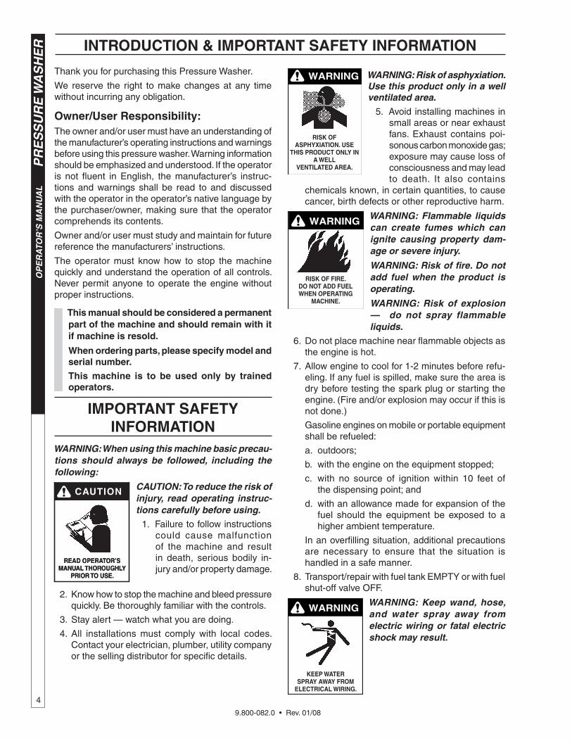
WARNING: When using this machine basic precau-tions should always be followed, including the following:
CAUTION: To reduce the risk of injury, read operating instruc-tions carefully before using.
1. Failure to follow instructions could cause malfunction of the machine and result in death, serious bodily in-jury and/or property damage.
2. Know how to stop the machine and bleed pressure quickly. Be thoroughly familiar with the controls.
�. Stay alert — watch what you are doing.
4. All installations must comply with local codes. Contact your electrician, plumber, utility company or the selling distributor for specific details.
READ OPERATOR’S MANUAL THOROUGHLy
PRIOR TO USE.
READ OPERATOR’S MANUAL THOROUGHLy
PRIOR TO USE.
WARNING
RISk Of ASPHyxIATION. USE
THIS PRODUCT ONLy IN A WELL
vENTILATED AREA.
WARNING: Risk of asphyxiation. Use this product only in a well ventilated area.
5. Avoid installing machines in small areas or near exhaust fans. Exhaust contains poi-sonous carbon monoxide gas; exposure may cause loss of consciousness and may lead to death. It also contains
chemicals known, in certain quantities, to cause cancer, birth defects or other reproductive harm.
WARNING
RISk Of fIRE. DO NOT ADD fUEL WHEN OPERATING
MACHINE.
WARNING: Flammable liquids can create fumes which can ignite causing property dam-age or severe injury.
WARNING: Risk of fire. Do not add fuel when the product is operating.
WARNING: Risk of explosion — do not spray flammable liquids.
6. Do not place machine near flammable objects as the engine is hot.
7. Allow engine to cool for 1-2 minutes before refu-eling. If any fuel is spilled, make sure the area is dry before testing the spark plug or starting the engine. (Fire and/or explosion may occur if this is not done.)
Gasoline engines on mobile or portable equipment shall be refueled:
a. outdoors;
b. with the engine on the equipment stopped;
c. with no source of ignition within 10 feet of the dispensing point; and
d. with an allowance made for expansion of the fuel should the equipment be exposed to a higher ambient temperature.
In an overfilling situation, additional precautions are necessary to ensure that the situation is handled in a safe manner.
8. Transport/repair with fuel tank EMPTY or with fuel shut-off valve OFF.
WARNING
kEEP WATER SPRAy AWAy fROM
ELECTRICAL WIRING.
WARNING: Keep wand, hose, and water spray away from electric wiring or fatal electric shock may result.

9.800-082.0 • Rev. 01/08
5
PR
ES
SU
RE
WA
SH
ER
OP
ER
ATO
R’S
MA
NU
AL
INTRODUCTION & IMPORTANT SAfETy INfORMATION
RISk Of ExPLOSION: DO NOT USE WITH
fLAMMAbLE LIqUIDS.
WARNING WARNING: Flammable liquids can create fumes which can ignite, causing property dam-age or severe injury.
WARNING: Risk of explosion — Do not spray flammable liquids.
9. Do not allow acids, caustic or abrasive fluids to pass through the pump.
10. Keep operating area clear of all persons.
WARNING
USE PROTECTIvE EyE WEAR
AND CLOTHING WHEN OPERATING THIS EqUIPMENT.
WARNING: High pressure spray can cause paint chips or other particles to become airborne and fly at high speeds. To avoid personal injury, eye, hand and foot safety devices must be worn.
11. Eye, hand, and foot protection must be worn when using this equipment.
TRIGGER GUN kICkS bACk - HOLD WITH
bOTH HANDS
WARNING WARNING: Grip cleaning wand securely with both hands be-fore starting. Failure to do this could result in injury from a whipping wand.
RISk Of INjECTION OR SEvERE INjURy TO PERSONS. kEEP CLEAR Of NOzzLE.
WARNING WARNING: High pressure de-veloped by these machines will cause personal injury or equip-ment damage. Keep clear of nozzle. Use caution when oper-ating. Do not direct discharge stream at people, or severe in-jury or death will result.
12. To reduce the risk of injury, close supervision is necessary when a machine is used near children. Do not allow children to operate the pressure washer. This machine must be attended during operation.
WARNING
RISk Of INjURy fROM fALLS WHEN
USING LADDER.
WARNING: Be extremely careful when using a ladder, scaffold-ing or any other relatively un-stable location. The cleaning area should have adequate slopes and drainage to reduce the possibility of a fall due to slippery surfaces.
1�. Do not overreach or stand on unstable support. Keep good footing and balance at all times.
14. Follow the maintenance instructions specified in the manual.
WARNING
PROTECT fROM fREEzING
WARNING: Protect machine from freezing.
15. To keep machine in best operating conditions, it is important you protect ma-chine from freezing. Failure to protect machine from freez-ing could cause malfunction
of the machine and result in death, serious bodily injury, and/or property damage. Follow storage instructions specified in this manual.
16. Inlet water must be clean fresh water and no hotter then 90°F.
17. Never make adjustments on machine while in operation.
18. Be certain all quick coupler fittings are secured before using pressure washer.
19. Manufacturer will not be liable for any changes made to our standard machines, or any compo-nents not purchased from us.
20. The best insurance against an accident is precau-tion and knowledge of the machine.
21. Do not operate this machine when fatigued or under the influence of alcohol, prescription medi-cations, or drugs.
PRE-OPERATION CHECk Check pump oil level. (Use SAE �0W non-deter-gent oil). Dipstick is located on top of pump.
Cold water supply (minimum 6 gpm, 5/8", 20 psi)
Hose, wand, nozzles (nozzle sizes per serial plate)
Water filter (intact, non restrictive)
Fuel (unleaded 86 or higher octane)
Open spray gun to relieve pressure before start-ing.
Engine oil (SAE 10W�0)
•
•
•
•
•
•
•

9.800-082.0 • Rev. 01/08
OP
ER
ATO
R’S
MA
NU
AL
PR
ES
SU
RE
WA
SH
ER
6
CHAUD!
OIL ALERT
WHEN OIL LEVEL LOW,
ENGINE STOPS IMMEDIATELY.
READ OWNER'S MANUAL BEFORE OPERATION.
LIRE LE MANUEL D'UTILISATEUR AVANT USAGE.
VOR INBETRIEBNAHME UNBEDINGT
BEDIENUNGSANLEITUNG DURSCHLESEN.
NO UTILIZAR SIN ANTES NO HABER LEIDO EL MANUAL.
Pump — Develops high pressure.
Starter Grip— Used for starting the engine manu-ally.
Spray Gun — Controls the application of water and detergent onto cleaning surface with trigger device. Includes safety latch.
Detergent Injector — Allows you to siphon and mix detergents.
Wand — Must be connected to the spray gun.
High Pressure Hose — Connect one end to water pump discharge nipple and the other end to spray gun.
Pump Protector — Cycles fresh cool water through pump when recirculating water reaches 140°F.
Note: If trigger on spray gun is released for more than 1-2 minutes, water will leak from valve. Warm water will discharge from pump protector onto floor. This system prevents internal pump dam-age.
COMPONENT IDENTIfICATION
Starter Grip
Trigger
Spray Gun
High Pressure Hose
Pump
Straight Through Wand
Pressure Nozzle
Garden Hose (not included)
Inlet Screen
Pump Protector
Unloader
Detergent bucket
(not included)
Detergent Injector

9.800-082.0 • Rev. 01/08
7
PR
ES
SU
RE
WA
SH
ER
OP
ER
ATO
R’S
MA
NU
AL
STEP 1: Attach the handle to the frame of the pressure washer. Note: It may be necessary to move the handle supports from side to side in order to align the handle so it will slide over the frame supports.
STEP 2: Insert the carriage bolt through the holes from the outside of the unit and attach a nut from the inside of the machine. Tighten nuts.
STEP 3: Attach the spray gun/hose storage handle and bracket to handle. Tighten nuts.
STEP 4: Attach the high pressure hose to the spray gun using teflon tape on hose threads.
STEP 7: Release the coupler collar and push the nozzle until the collar clicks. Pull the nozzle to make sure it is seated properly.
STEP 8: Connect the high pres-sure hose to the pump discharge nipple. Push coupler collar forward until secure.
STEP 5: Attach nozzle extension to spray gun/wand. Tighten both by hand.
STEP 6: Pull the spring-loaded col-lar of the wand coupler back to insert your choice of pressure nozzle.
STEP 9: Connect (7.5m) garden hose to the cold water source.
ASSEMbLy INSTRUCTIONS
STEP 10: Check inlets filters, remove debris, then connect the garden hose to pump water inlet. CAUTION: Do not run the pump without water or pump damage will result.
Alignment Holes
Handle
frame Assy.
Carriage bolt
Nut
Studs
Nut
Hose/Gun Storage bracket
Safety Latch
Spray Gun
High Pressure Hose
Nozzle ExtensionSpray
Gun/Wand
Wand Coupler
PressureNozzle
Pressure Nozzle
Wand Coupler
WandCollar
Pump Discharge
Nipple
High Pressure
Hose
Cold Water
Source
Garden Hose
Pump Water Inlet
Garden Hose
Coupler Collar
bolts

9.800-082.0 • Rev. 01/08
OP
ER
ATO
R’S
MA
NU
AL
PR
ES
SU
RE
WA
SH
ER
8
STEP 1: Check engine oil level. Oil level should be level with the bottom of the oil filler neck. Be sure the machine is level when checking the oil level. (Refer to the engine's operating manual included with machine.) We recommend that the oil be changed after the first 5 hours of use, then once every 50 hours. Note: Improper oil levels will cause low oil sensor to shut off engine. IMPORTANT! Do not run engine with high or low oil levels as this will cause engine damage.
STEP 2: Remove shipping cap and install oil dipstick. Check pump oil level by using dipstick or observe oil level in oil window (if equipped). Use 30 wt. (non detergent) oil.
STEP 5: Rotate the fuel shut-off valve to the "On" position. Slide the fuel valve lever to the "ON" position. When the engine is not in use, leave the fuel valve in the "OFF" position.
STEP 4: Trigger the spray gun to eliminate trapped air then wait for a steady flow of water to emerge from the spray nozzle.
OPERATING INSTRUCTIONS
STEP 3: Fill gas tank with unleaded gasoline. Do not use leaded gasoline.
STEP 6: Move the choke lever to the "Choke" posi-tion (on a warm engine, leave the choke lever in the run position). Move the choke lever to the "Closed" position. To restart a warm engine, leave the choke lever in the "Open" position.
Oil Dipstick Dipstick
Oil Window
Gas Tank
Choke Lever
fuel valve
Choke
fuel valve

9.800-082.0 • Rev. 01/08
9
PR
ES
SU
RE
WA
SH
ER
OP
ER
ATO
R’S
MA
NU
AL
STEP 8: Turn the engine switch to "On" position.
On Briggs engines, move the throttle lever to "Fast" position, shown on the engine as a rabbit.
STEP 9: Pull the starter grip. If the engine fails to start after 2 pulls, squeeze the trigger gun to release pressure and repeat step. Return starter gently. After the engine warms up enough to run smoothly, move choke to run position and throttle to fast position.
CAUTION: Small engines may kick back. Do not hold pull starter grip tightly in hand.
OPERATING INSTRUCTIONS (CON'T)
WARNING! Never replace nozzles without engaging the safety latch on the spray gun trigger.
The five color-coded quick connect nozzles provide a wide array of spray widths from 0° to 45° and are easily accessible when placed in the convenient rubber nozzle holder, which is provided on the front of the machine.
NOTE: For a more gentle rinse, select the white 40° or green 25° nozzle. To scour the surface, select the yellow 15° or red 0° nozzle. To apply de-tergent select the black nozzle.
NOzzLES
Safety Latch
On-Off Switch

9.800-082.0 • Rev. 01/08
OP
ER
ATO
R’S
MA
NU
AL
PR
ES
SU
RE
WA
SH
ER
10
WARNING: Some detergents may be harmful if inhaled or ingested, causing severe nau-sea, fainting or poisoning. The harmful elements may cause property damage or severe injury.
STEP 1: Connect detergent injector to discharge nipple on machine.
Connect high pressure hose to injector with quick cou-pler. (Check to make sure locking coupler sleeves are in proper position before applying water pressure).
STEP 2: Use detergent designed specifically for pressure washers. Prepare detergent solution as required by the manufacturer. Fill a container with pressure washer detergent. Place the filter end of detergent suction tube into the detergent container.
STEP 3: With safety latch on spray gun engaged, secure black detergent nozzle into quick cou-pler. NOTE: Detergent cannot be applied using red, yellow, green or white nozzles.
STEP 4: With the engine running, pull trigger to operate machine. Liquid detergent is drawn into the machine and mixed with water. Apply detergent to work area. Do not allow detergent to dry on surface.
IMPORTANT: You must flush the detergent injec-tion system after each use by placing the suction tubeinto a bucket of clean water, then run the pres-sure washer in low pressure for 1-2 minutes.
THERMAL PUMP PROTECTIONIf you run the engine on your pressure washer for 1-2 minutes without pressing the trigger on the spray gun, circulating water in the pump can reach high tempera-tures. When the water reaches this temperature, the pump protector engages and cools the pump by dis-charging the warm water onto the ground. This thermal device prevents internal damage to the pump.
CLEANING TIPSPre-rinse cleaning surface with fresh water. Place de-tergent suction tube directly into cleaning solution and apply to surface at low pressure (for best results, limit your work area to sections approximately 6 feet square and always apply detergent from bottom to top). Allow detergent to remain on surface 1-� minutes. Do not al-low detergent to dry on surface. If surface appears to be drying, simply wet down surface with fresh water. If needed, use brush to remove stubborn dirt. Rinse at high pressure from top to bottom in an even sweep-ing motion keeping the spray nozzle approximately 1 foot from cleaning surface. Use overlapping strokes as you clean and rinse any surface. For best surface cleaning action spray at a slight angle.
Recommendations: • Before cleaning any surface, an inconspicuous
area should be cleaned to test spray pattern and distance for maximum cleaning results.
• If painted surfaces are peeling or chipping, use extreme caution as pressure washer may remove the loose paint from the surface.
• Keep the spray nozzle a safe distance from the surface you plan to clean. High pressure wash a small area, then check the surface for damage. If no damage is found, continue to pressure wash-ing.
CAUTION - Never use: • Bleach, chlorine products and other corrosive
chemicals • Liquids containing solvents (i.e., paint thinner,
gasoline, oils) • Tri-sodium phosphate products • Ammonia products • Acid-based productsThese chemicals will harm the machine and will dam-age the surface being cleaned.
RINSINGIt will take a few seconds for the detergent to clear. Apply safety latch to spray gun. Remove black soap nozzle from the quick coupler. Select and install the desired high pressure nozzle. NOTE: You can also stop detergent from flowing by simply removing detergent siphon tube from bottle.
WARNING
Soap Nozzle
Detergent Injector
Discharge Nipple
Strainer
quick Coupler
High Pressure Hose
DETERGENT AND GENERAL CLEANING TECHNIqUES

9.800-082.0 • Rev. 01/08
11
PR
ES
SU
RE
WA
SH
ER
OP
ER
ATO
R’S
MA
NU
AL
SHUTTING DOWN AND CLEAN-UP
STEP 1: Remove detergent suc-tion tube from container and insert into one gallon of fresh water. Slide nozzle forward for low pressure or to connect black detergent nozzle. Pull trigger on spray gun and siphon water for one minute.
STEP 2: Turn off the engine. STEP 3: Turn off water supply.
STEP 5: Disconnect the garden hose from the water inlet on the machine.
STEP 6: Disconnect the high pressure hose from pump dis-charge nipple.
STEP 7: Engage the spray gun safe-ty lock.
STEP 4: Press trig-ger to release water pressure.
CAUTION: Always store your pressure washer in a location where the temperature will not fall below 32°F (0°C). The pump in this machine is susceptible to permanent damage if frozen. FREEZE DAMAGE IS NOT COVERED BY WARRANTY. 1. Stop the pressure washer, squeeze spray gun trig-
ger to release pressure. 2. Detach water supply hose and high pressure
hose. �. Turn on the machine for a few seconds, until re-
maining water exits. Turn engine off immediately. 4. Drain the gas from the engine. 5. Do not allow high pressure hose to become
kinked. 6. Store the machine and accessories in a room which
does not reach freezing temperatures.CAUTION: Failure to follow the above directions will result in damage to your pressure washer.When the pressure washer is not being operated or is being stored for more than one month, follow these instructions: 1. Replenish engine oil to upper level. 2. Drain gasoline from fuel tank, fuel line, fuel valve
and carburetor. �. Pour about one teaspoon of engine oil through
the spark plug hole, pull the starter grip several
times and replace the plug. Then pull the starter grip slowly until you feel increased pressure which indicates the piston is on its compression stroke and leave it in that position. This closes both the intake and exhaust valves to prevent rusting of cylinder.
4. Cover the pressure washer and store in a clean, dry place that is well ventilated away from open flame or sparks. NOTE: The use of a fuel additive, such as STA-BIL®, or an equivalent, will minimize the formulation of fuel deposits during shortage. Such additives may be added to the gasoline in the fuel tank of the engine, or to the gasolinee in a storage container.
After Extended StorageCAUTION: Prior to restarting, thaw out any pos-sible ice from pressure washer hoses, spray gun or wand.
Engine MaintenanceDuring the winter months, rare atmosheric conditions may develop which will cause an
icing condition in the carburetor. If this develops, the engine may run rough, lose power and may stall. This temporary condition can be overcome by deflecting some of the hot air from the engine over the carburetor area. NOTE: Refer to the engine manufacturer's manual for service and maintenance of the engine.
STORAGE
On-OffSwitch
Pump Water Inlet
Pump Discharge
Nipple
Safety Latch
Garden Hose

9.800-082.0 • Rev. 01/08
PR
ES
SU
RE
WA
SH
ER
T
rou
ble
sho
oti
ng
Gu
ide
12
TROUbLESHOOTING
PRObLEM POSSIbLE CAUSE SOLUTION
LOW OPERATINGPRESSURE
Insufficient water supply. Closed faucet. Inlet hose kinked
Use larger garden hose; clean inlet water screen. Open faucet.
Clogged inlet hose strainer Check plumbing system for leaks. Re-tape leaks with Teflon tape.
Faulty or improperly adjusted unloader valve
Adjust unloader for proper pressure. Install repair kit when needed. Contact local deal-er.
Worn packing in pump Contact local dealer.
Machine has been stored in freezing temperatures
Thaw out machine completely, including hose, spray gun and wand.
Slow engine RPM Contact local dealer.
fLUCTUATING PRESSURE
Worn or dirty pump valves Contact local dealer.
Nozzle is obstructed Blow out or remove debris with fine needle.
Pump sucking air, inlet hose leak-ing
Check all pump lines and connections.
PRESSURE LOW AfTER PERIOD Of NORMAL USE
Nozzle worn Replace nozzle.
Unloader valve worn Replace unloader valve.
ENGINE WILL NOT START OR STOPS WHILE OPERATING
Low oil shutdown Fill engine with oil.
Out of gas Fill fuel tank.
Water in gasoline Drain gas tank; fill with clean fuel.
ENGINE ISOvERLOADED
Nozzle partially blocked Clean nozzle.
Excessive pressure from high engine RPM
Adjust engine throttle to lower RPM.
WATER OR OIL LEAkING fROM bOTTOM Of PUMP
A small amount of leaking is nor-mal
If excessive leaking occurs, Contact local dealer.
PRESENCE Of WATERIN PUMP OIL
Water sprayed at machine Change oil. Direct spray away from ma-chine.
High humidity in air Check and change oil twice as often.
Piston packing worn. Oil seal worn.
Contact local dealer.

9.800-082.0 • Rev. 01/08
1�
PR
ES
SU
RE
WA
SH
ER
Trou
blesh
oo
ting
Gu
ide
TROUbLESHOOTING
PRObLEM POSSIbLE CAUSE SOLUTION
ENGINE OPERATES fOR 15 MIN. THEN STOPS
Not enough gas or engine oil Fill tank with gas. Check oil level.
Vapor lock developed by heat of day
Keep gas tank full to avoid vapor locking.
Obstruction in fuel filter Clean or replace fuel filter.
ENGINE LACkS POWER
Dirty air filter Replace air filter.
ENGINE fALTERS Choke is opened too soon Move choke to halfway position until engine runs smoothly.
WATER DRIPPING fROM UNDER PUMP
Piston packing worn Contact local dealer.
O-Ring plunger retainer worn Contact local dealer.
Cracked piston Contact local dealer.
OIL DRIPPING Oil seal worn or damaged Contact local dealer.
WATER LEAk-ING fROM PUMP PROTECTOR
Spray gun closed with machine running 5 minutes or longer
Open spray gun or turn off machine.
Excess water supply pressure Place a pressure regulator at end of 50' garden hose.
NO DETERGENT Detergent suction tube not properly connected to machine
Check connection.
Detergent is too thick Dilute detergent. For best results, use manufac-turers detergent.
Detergent filter valve is at low-est setting
Set detergent filter valve to a higher setting.
Filter on detergent suction tube is clogged
Run warm water through filter to remove debris.
Damaged or clogged detergent suction tube
Remove obstruction or replace detergent suc-tion tube.
A high pressure nozzle is at-tached.
Replace with black detergent nozzle.
Discharge nozzle is obstructed Blow out or remove debris with fine needle.
GARDEN HOSE CONNECTION LEAkS
Loose fittings Tighten fittings.
Missing/worn rubber washer Insert new washer.
SPRAy WAND LEAkS
Spray wand not properly at-tached
Slide the spray wand into the gun. Turn the wand collar clockwise onto the spray gun threads until tight.
Broken o-ring Call your distributor and order an o-ring.
PUMP IS NOISy Pump is sucking air Check that hoses and fittings are air tight. Turn off machine and purge pump by squeezing trigger gun until a steady flow of water emerges through nozzle.

9.800-082.0 • Rev. 01/08
OP
ER
ATO
R’S
MA
NU
AL
PR
ES
SU
RE
WA
SH
ER
14
PREvENTATIvE MAINTENANCE
This pressure washer was produced with the best available materials and quality craftsmanship. However, you as the owner have certain responsibilities for the correct care of the equipment. Attention to regular preventa-tive maintenance procedures will assist in preserving the performance of your equipment. Contact your dealer for maintenance. Regular preventative maintenance will add many hours to the life of your pressure washer. Perform maintenance more often under severe conditions.
OIL CHANGE RECORDCheck pump oil and engine oil level before first use of your new pressure washer.
Date Oil Changed Month/Day/year
Estimated Operating Hours Since Last
Oil ChangeDate Oil Changed Month/Day/year
Estimated Operating Hours Since Last
Oil Change
MAINTENANCE SCHEDULE
Engine Oil
Inspect Daily
Change First month or 20 hours. Every 100 hours or every 6 months after first month.
Filter Every 50 hours.
Air Cleaner/FilterInspect Every 50 hours
Clean Monthly
Engine Fuel Filter 500 hours or 6 months
Spark Plug Maintenance �00 hours or annually
Clean Fuel Tank(s) Annually
Replace Fuel LInes Annually
Pump OilInspect Oil level daily
Change After first 50 hours, then every 500 hours or annually
Replace High Pressure Nozzle Every 6 months
Replace Quick Connects/O-Rings Annually/As needed
Clean Water Screen/Filter Weekly
Replace HP Hose Annually (if there are any signs of wear)

9.800-082.0 • Rev. 01/08
15
PR
ES
SU
RE
WA
SH
ER
OP
ER
ATO
R’S
MA
NU
AL
CHAUD!
OIL ALERT
WHEN OIL LEvEL LOW,
ENGINE STOPS IMMEDIATELy.
READ OWNER'S MANUAL bEfORE OPERATION.
LIRE LE MANUEL D'UTILISATEUR AvANT USAGE.
vOR INbETRIEbNAHME UNbEDINGT
bEDIENUNGSANLEITUNG DURSCHLESEN.
NO UTILIzAR SIN ANTES NO HAbER LEIDO EL MANUAL.
ExPLODED vIEW
39
46
36
37 38
25
281535
27
28
30
32
33
34
35
65
2
3
9
12
17
14
7
20
19
18
23
1
22
47
9
12
10
2
46 45
44
1125
24
26
53
43
4241 5352
21
40
24
1353
Model 110
E-z Start valve for 9, 11, 13 HP Honda
Engines Only
29
29
31
29
51
49
12
12
20
48
4844
50
16
6 3
5
4
2
Models 100 & 101
18
54
6
Models 110, 100, 101, 102, 103, 104
55
4
56

9.800-082.0 • Rev. 01/08
OP
ER
ATO
R’S
MA
NU
AL
PR
ES
SU
RE
WA
SH
ER
16
ExPLODED vIEW PARTS LIST
ITEM PART NO. DESCRIPTION qTy
1 Engine, See Specifications Page
2 Pump, See Specifications Page
� Unloader, See Specifications Page
4 9.804-025.0 Pump Protector, 1/4" 145° (100, 101) 1 8.707-256.0 Pump Protector, 1/2" PTP (102, 104, 10�) 1
5 9.802-146.0 Swivel, 1/2" MP x �/4" GHF (100, 101, 102, 104, 10�) 1
6 9.802-171.0 Nipple, �/8" x �/8" NPT ST Fem (101) 1 9.802-171.0 Nipple, �/8" x �/8" MPT Male (100, 102, 10�, 104) 1
7 9.802-142.0 Hose, 1/4" Push-on (E-Z-Start, 9 HP, 11 HP, 1� HP Honda) 14 in
8 8.707-182.0 s Coupler, Twist Connect, M22-F x �/8" FNPT (2�2��6 and 2��26) 1
9 9.802-142.0 Hose, Barb, 1/4" Barb x 1/8" MP, 90° (E-Z Start) 1 (11 HP, 1� HP Honda) 2 8.706-958.0 Hose Barb, 1/4' Barb x 1/4" Pipe (9 HP) 1
10 9.802-190.0 Valve, E-Z Start �/8" MPT x 1/8" FPT(9HP, 11HP, 1�HP Honda) 1
11 9.80�-126.0 Base, CW Direct, Black 1
12 9.802-210.0 Clamp, Hose, (E-Z Start, 9 HP, 11 HP , 1� HP Honda) 4 (5.5HP, 6HP) 2
1� 9.802-711.0 Bolt, 5/16-24" x 1" NF, HH 4 9.802-722.0 Bolt, �/8" x 1-1/4" NC, HH (9 HP, 11 HP, 1� HP) 4 9.802-707.0 Bolt, 5/16"-24 x �/4" 4
14 9.802-216.0 Injector, Detergent, Assembly All Models Except (110) 1
9.802-216.0 Injector, Chemical, Non-Adjust 1 8.707-057.0 Strainer, Plastic, 1/4" Hose Barb 1 9.802-251.0 Tube, 1/4" x 1/2" Clear Vinyl 6 ft.
15 9.800-72�.0 Label, Instructions 1
16 9.802-160.0 Strainer, Plastic, 1/4" Hose Barb 1
17 Hose, High Pressure, See Specifications Page
18 9.802-22�.0 Spray Gun, SK2, �/8" Inlet, Lance W/M22CPLR 1 8.711-�48.0 Spray Gun, AP 1000 1
19 9.802-220.0 Wand, 18" M22 x 1/4" QC 1 9.802-219.0 Wand Assy, Side Grip w/1/4" Coupler 1
ITEM PART NO. DESCRIPTION qTy
20 Nozzle Size, See Page 19 For Proper Size 4-1280�000 Nozzle, �.0 0° Red 1 4-1280�015 Nozzle, �.0 15° Yellow 1 4-1280�025 Nozzle, �.0 25° Green 1 4-1280�040 Nozzle, �.0 40° White 1 4-1280�500 Nozzle, �.5 0° Red 1 4-1280�515 Nozzle, �.5 15° Yellow 1 4-1280�525 Nozzle, �.5 25° Green 1 4-1280�540 Nozzle, �.5 40° White 1 4-12804000 Nozzle, 4.0 0° Red 1 4-12804015 Nozzle, 4.0 15° Yellow 1 4-12804025 Nozzle, 4.0 25° Green 1 4-12804040 Nozzle, 4.0 40° White 1 4-16540 Nozzle, Compl, QCEM-6540, Brass (All Models) 1
21 9.80�-097.0 Axle, 5/8" x 20.125" Long 1
22 9.800-006.0 Label, HOT 1
2� 9.802-71�.0 Bolt, 5/16" x 1-1/2", NC HH (5 HP, 5.5 HP, 6.5 HP) 4 9.802-727.0 Bolt, �/8" x 1-�/4" Tap (9 HP, 11 HP, 1� HP) 4
24 9.802-807.0 Washer, �/8" SAE, Flat 6
25 9.802-779.0 Nut, �/8" ESNA, NC 6
26 9.802-728.0 Bolt, �/8" x 2" NC, HH 4
27 9.80�-114.0 Retainer Bracket, Handle, Black 2
28 9.802-77�.0 Nut, 1/4" ESNA, NC 6
29 9.802-802.0 Washer, 1/4" Flat 6
�0 9.802-064.0 Grommet, Rubber, Nozzle Holder, 5
�1 9.802-778.0 Nut, 5/16" Flange, Whiz Loc 2
�2 9.80�-119.0 Handle, Grab, Chrome 1
�� 9.80�-126.0 Plate, Warning, Black 1
�4 9.80�-098.0 Hanger, Hose/Wand 1
�5 9.802-706.0 Bolt, 1/4"-20 x 1-�/4", Carriage, Zinc 6
�6 9.80�-119.0 Handle, Lower Grab, Chrome 1
�7 9.802-066.0 Pad, Soft Rubber 2
�8 9.802-817.0 Washer, �/8" x 1" Steel 2
�9 9.802-729.0 Bolt, �/8" x 2-1/4" HH, Grd. 5 2
40 9.802-804.0 Bolt, Carriage, 5/16" x 1-�/4" 4
41 9.802-804.0 Washer, 5/16" Flat 4
42 9.802-776.0 Nut, 5/16" ESNA, NC 4
4� 9.80�-12�.0 Handle, Bumper, Chrome 1
44 9.802-10�.0 Bushing, 5/8" Snap 2
45 9.802-270.0 Wheel & Tire Assy, 4" Steel Rim w/Tube 2
46 9.802-782.0 Collar, 5/8" Bore Shaft 2
47 9.800-008.0 Label, Cool Engine Before Filling 1
48 9.802-810.0 Washer, 5/8" Flat 2

9.800-082.0 • Rev. 01/08
17
PR
ES
SU
RE
WA
SH
ER
OP
ER
ATO
R’S
MA
NU
AL
ExPLODED vIEW PARTS LIST CONT.
ITEM PART NO. DESCRIPTION qTy
49 9.802-958.0 Key, .185 Sqr x 1.75" (5 HP, 5.5 HP, 6.5 HP) 1
50 9.802-251.0 Tube, 1/4" x 1/2" Clear Vinyl 6 ft.
51 9.800-049.0 Label, Manufacturer's Cleaning Solution 1
52 9.802-776.0 Nut, 5/16" ESNA, NC (5 HP, 5.5 HP, 6.5 HP) 4 9.802-779.0 Nut, �/8" ESNA, NC (9 HP, 11HP, 1� HP) 4
5� 9.802-804.0 Washer, 5/16" Flat (5 HP, 5.5 HP, 6.5 HP) 8 9.802-807.0 Washer, �/8" Flat (9 HP, 11 HP, 1� HP) 12
54 9.802-169.0 Coupler, �/8" Male Brass 1
55 8.706-854.0 Tee, 1/4" Branch, Male 1
56 9.802-81�.0 Lock Washer 4
s Not Shown

9.800-082.0 • Rev. 01/08
PR
ES
SU
RE
WA
SH
ER
Sp
ecifi
cati
on
s
18
SPECIfICATIONS
Machine Pressure Nozzle Hose Pump Pump Unloader Engine Engine
Model GPM (PSI) Size Part # Model Part # Part # Hp Part #
1.575-100.0 2.� 2400 �.0 8.7�9-125.0 KG25�0G 9.80�-822.0 9.80�-899.0 GC160 (5.5) 9.802-�16.0
1.575-101.0 2.5 2700 �.0 8.7�9-125.0 KG25�0G 9.80�-822.0 9.80�-899.0 GX200 (6.5) 9.802-�17.0
1.575-102.0 �.0 �000 �.5 8.7�9-125.0 KG�0�5G1 9.804-0�4.0 9.80�-899.0 GX270 (9) 9.802-�15.0
1.575-104.0 �.8 �500 4.0 8.7�9-20�.0 KS4040G 9.802-�50.0 9.80�-900.0 GX�90 (1�) 9.802-�22.0
1.575-110.0 2.� 2�00 �.0 8.7�9-125.0 2427G 9.120-0�2.0 9.80�-900.0 GC160 9.802-�16.0
1.575-10�.0 �.8 �200 4.0 8.7�9-20�.0 KS�540G1 9.802-�49.0 9.80�-900.0 GX�90 9.802-�16.0

9.800-082.0 • Rev. 01/08
19
PR
ES
SU
RE
WA
SH
ER
OP
ER
ATO
R’S
MA
NU
AL
vbA35 UNLOADER ExPLODED vIEW
vbA35 UNLOADER ExPLODED vIEW PARTS LIST
9.803-899.0 & 9.803-900.0 Unloader, 25 lpm @ 240 bAR, fits with kG2530 Pump
ITEM PART NO. DESCRIPTION kIT qTy
1 9.80�-902.0 Body Valve (KG) 19.80�-901.0 Body Valve (KS) 1
2 9.80�-90�.0 O-Ring A, C 1
� 9.80�-904.0 Seat C 1
4 9.80�-905.0 Ball, Sub-assy C 1
5 9.80�-906.0 O-Ring A 1
6 9.80�-907.0 Guide Bushing 1
7 9.80�-908.0 Teflon Ring A 1
8 9.80�-909.0 O-Ring A 2
9 9.80�-910.0 O-Ring A 1
10 9.80�-911.0 Connector 1
11 9.80�-912.0 Teflon Ring A 1
12 9.80�-91�.0 Stem C 1
1� 9.80�-914.0 Connector, Female 1
14 9.80�-191.0 O-Ring A, B 1
ITEM PART NO. DESCRIPTION kIT qTy
15 9.80�-916.0 Spring B 1
16 9.80�-917.0 Poppet B 1
17 9.802-89�.0 Seal Washer �/8 2
18 9.80�-920.0 Banjo Bolt, �/8 w/ 1/8 Pilot
1
19 9.80�-915.0 Banjo Bolt 1/2 1
20 9.80�-921.0 Seal Washer 1/2 2
21 9.80�-922.0 Plate C 1
22 9.80�-92�.0 Spring C 1
2� 9.80�-924.0 Set Screw 1
24 9.80�-925.0 Nut 1
25 9.80�-926.0 Brass Handle 1
Kit A 9.80�-927.0 O-Ring Repair Kit
Kit B 9.80�-928.0 Outlet Kit
Kit C 9.80�-929.0 Stem Repair Kit

9.800-082.0 • Rev. 01/08
OP
ER
ATO
R’S
MA
NU
AL
PR
ES
SU
RE
WA
SH
ER
20
ITEM PART NO. DESCRIPTION qTy
1 9.80�-9�8.0 Crankcase 1
2* See Kit Below Plunger Oil Seal �
�* 9.80�-9�9.0 O-Ring Ø1.78 x 28.�0 �
4* 8.717-�10.0 Pressure Ring, 15mm �
5* See Kit Below "V" Seal, 15mm 6
6* 9.80�-942.0 Support Ring 15mm 6
7* 9.80�-944.0 Intermediate Ring 15mm �
8 9.802-926.0 Brass Plug, 1/2" 1
9 9.80�-199.0 Copper Washer 1/2" 1
10 9.80�-946.0 Manifold Housing 1
11* 9.80�-947.0 O-Ring Ø1.78 x 15.54 6
12* See Kit Below Valve Assembly 6
1�* 9.80�-948.0 O-Ring Ø2.62 x 18.77 6
14 9.80�-949.0 Valve Plug 6
15 9.80�-950.0 Washer, Copper 1
16 9.80�-951.0 Brass Plug G1/4 1
17 9.80�-952.0 Manifold Stud Bolt 8
ITEM PART NO. DESCRIPTION qTy
18 9.802-884.0 Washer 8
19 9.80�-198.0 Copper Washer �/8" 1
20 9.802-925.0 Brass Plug �/8" 2
25 9.802-9�9.0 Hexagonal Screw 9
26 9.80�-95�.0 Bearing Cover 1
27 9.80�-954.0 Seal Bearing 1
28 9.802-914.0 Snap Ring 1
29 9.80�-955.0 Ball Bearing 1
�0 8.717-069.0 Crankshaft (25�0G) 1
8.717-070.0 Crankshaft (�0�0G) 1
�1 9.80�-957.0 Oil Dip Stick 1
�2 9.804-581.0 O-Ring �.5� x 55.56 1
�� 9.804-582.0 Needle Roller Bearing 1
�4 8.717-212.0 Engine Flange 1
�5 9.80�-210.0 Spring Washer 4
�6 9.804-584.0 Flange Screw 4
9.803-822.0 kG2530G9.803-823.0 kG3030G
TORqUE SPECS
Item # Ft.-lbs
14 65
17 18
25 7.6
�6 8
�8 9
47 1�
kG PUMP ExPLODED vIEW
kG PUMP ExPLODED vIEW PARTS LIST

9.800-082.0 • Rev. 01/08
21
PR
ES
SU
RE
WA
SH
ER
OP
ER
ATO
R’S
MA
NU
AL
ITEM PART NO. DESCRIPTION qTy
�7 9.804-586.0 Crankshaft Seal 1
�8* 9.80�-959.0 Plunger Nut �
�9* See Kit Below Plunger, 15mm �
40* 9.80�-962.0 Copper Spacer �
41* 9.80�-96�.0 O-Ring Ø1.78x5.28 �
42* 9.80�-156.0 Teflon Ring �
4� 9.80�-964.0 Plunger Rod �
44 9.80�-965.0 Connecting Rod Pin �
45 9.80�-966.0 Connecting Rod �
46 9.80�-218.0 Spring Washer 6
47 8.9��-020.0 Connecting Rod Screw 6
48 9.80�-969.0 O-Ring 2.62 x 107.62 1
49 9.80�-968.0 Crankcase Cover 1
50 9.80�-197.0 Gasket, G�/8 1
51 9.80�-202.0 Sightglass G�/8 1
* Part available in kit (See below)
REPAIR kIT NUMbER 9.803-930.0 9.803-932.0 9.803-934.0 9.803-936.0 9.803-937.0
KIT DESCRIPTION Plunger Seal15mm
Complete Seal Packing
15mmPlunger 15mm
Complete Valve
Plunger Oil Seals
ITEM NUMBERS INCLUDED
�, 5, 62, �, 4, 5,
6, 7�8, �9, 40,
41, 4211, 12, 1� 2
NUMBER OF CYLINDERS KIT WILL SERVICE
� 1 1 6 �
kG PUMP ExPLODED vIEW

9.800-082.0 • Rev. 01/08
OP
ER
ATO
R’S
MA
NU
AL
PR
ES
SU
RE
WA
SH
ER
22
kS-1 PUMP ExPLODED vIEW
kS-1 PUMP ExPLODED vIEW PARTS LISTITEM PART NO. DESCRIPTION qTy
1 8.717-129.0 Crankcase 1
2 9.80�-196.0 Plunger Guide �
�* See Kit Below Plunger Oil Seal �
4* 9.80�-189.0 O-Ring Ø1.78 x �1.47 �
5* See Kit Below "V" Seal , 15mm 6
6* 8.717-�10.0 Pressure Ring, 15mm �
7* 8.717-179.0 Support Ring 15mm 6
8* 8.717-178.0 Intermed. Ring 15mm �
9 9.802-926.0 Brass Plug, 1/2" 1
10 9.80�-199.0 Copper Washer 1/2" 1
11 9.802-9�2.0 Manifold Housing 1
12* 9.80�-191.0 O-Ring Ø2.62 x 17.1� 6
1�* See Kit Below Valve Assembly 6
14* 9.80�-19�.0 O-Ring Ø2.62 x 20.29 6
15 9.802-928.0 Valve Plug 6
16 9.802-9�8.0 Manifold Stud Bolt 8
17 9.802-884.0 Washer 8
ITEM PART NO. DESCRIPTION qTy
18 9.80�-198.0 Copper Washer �/8" 1
19 9.802-925.0 Brass Plug �/8" 2
24 9.802-9�9.0 Hexagonal Screw 9
25 9.80�-210.0 Washer 4
26 9.80�-184.0 Closed Bearing Housing 1
27 8.717-225.0 O-Ring Ø 1.78 x 60.05 2
28 9.802-914.0 Snap Ring 1
29 9.80�-168.0 Double Row Ball Bearing 1
�0 9.80�-150.0 Crankshaft (KS�040G-1) 1
9.80�-151.0 Crankshaft (KS�540G-1) 1
9.80�-152.0 Crankshaft (KS4040G-1) 1
9.80�-15�.0 Crankshaft (KS50�0G-1)
�1 9.802-945.0 Set Screw 1
�2 9.802-921.0 Oil Dip Stick 1
�� 9.804-581.0 O-Ring Ø �.5� x 55.56
�4 9.80�-161.0 Needle Roller Bearing 1
�5 9.80�-18�.0 Engine Flange 1
9.841-643.0 kS3040G-19.802-349.0 kS3540G-19.802-350.0 kS4040G-19.803-409.0 kS5030G-1
TORqUE SPECS
Item # Ft.-lbs
15 75
16 �0
24 7.6
�7 10
45 4.5
55 1�

9.800-082.0 • Rev. 01/08
2�
PR
ES
SU
RE
WA
SH
ER
OP
ER
ATO
R’S
MA
NU
AL
kS-1 PUMP ExPLODED vIEW PARTS LIST (CONT.)
ITEM PART NO. DESCRIPTION qTy
�6 9.80�-221.0 Spring Washer 4
�7 9.80�-240.0 Flange Screw 4
�8 9.80�-24�.0 Engine Screw, 5/16" 4
�9 9.80�-215.0 Washer 4
40 9.802-889.0 Spring Washer 4
41 9.80�-244.0 Engine Screw �/8" 4
42 9.80�-216.0 Washer 4
4� 9.80�-217.0 Spring Washer 4
44 9.80�-142.0 Crankshaft Seal 1
45* 9.80�-959.0 Plunger Nut �
46* See Kit Below Plunger, 15mm �
47* 9.80�-962.0 Copper Spacer �
48* 9.80�-96�.0 O-Ring Ø1.78x5.28 �
49* 9.80�-156.0 Teflon Ring �
50 9.80�-145.0 Plunger Rod �
51 9.802-91�.0 Snap Ring 6
52 9.802-916.0 Connecting Rod Pin �
5� 9.80�-158.0 Connecting Rod �
54 9.80�-218.0 Spring Washer 6
55 9.80�-2�8.0 Connecting Rod Screw 6
56 8.9��-016.0 Cover Gasket 1
57 8.717-145.0 Crankcase Cover 1
58 9.80�-906.0 O-Ring, Ø 1.78 x 14 1
59 9.80�-202.0 Sight Glass, G�/4 1
* Part available in kit (See below)
REPAIR kIT NUMbER 9.802-622.0 9.802-623.0 8.933-023.0 9.802-603.0 9.802-609.0
KIT DESCRIPTIONPlunger Seal
15mmComplete
Seal Packing 15mm Plunger 15mmComplete
ValvePlunger Oil
Seals
ITEM NUMBERS INCLUDED
4, 5, 7 4, 5, 6, 7, 845, 46, 47,
48, 4912, 1�, 14 �
NUMBER OF CYLINDERS KIT WILL SERVICE
� 1 1 6 �


9.800-082.0 • Rev. 01/08
PR
ES
SU
RE
WA
SH
ER
WA
RR
AN
TY
WHAT THIS WARRANTY COVERSAll Kärcher commercial pressure washers are warranted by Kärcher to the original purchaser to be free from defects in materials and workmanship under normal use, for the periods specified below. This Limited Warranty, subject to the exclusions shown below, is calculated from the date of the original purchase, and applies to the original components only. Any parts replaced under this war-ranty will assume the remainder of the pressure washer’s warranty period.
FIVE YEAR PARTS AND ONE YEAR LABOR WARRANTYComponents manufactured by Kärcher, such as frames, handles, float tanks, fuel tanks, belt guards, and heating coils. Internal components on the oil-end of Kärcher axial pumps have a 5 year warranty. Period of warranty on axial pumps shall be one year.Kärcher crankshaft pumps have a 7 year warranty on non-wear parts. Heating coils are pro-rated at 25% after 2 years. Stainless steel coils have a 10 year warranty.
ONE YEAR PARTS AND ONE YEAR LABOR WARRANTYAll other components, excluding normal wear items as described below, will be warranted for one year on parts and labor. Parts and la-bor warranty on these parts will be for one year regardless of the duration of the original component manufacturer’s part warranty.
WARRANTY PROVIDED BY OTHER MANUFACTURERSMotors, generators, and engines, which are warranted by their respective manufacturers, are serviced through these manufacturers’ local authorized service centers. Kärcher is not authorized and has no responsibility to provide warranty service for such components. Motors manufactured outside of the United States will be warranted by Kärcher.
WHAT THIS WARRANTY DOES NOT COVERThis warranty does not cover the following items:
1. Normal wear items, such as nozzles, spray guns, discharge hoses, wands, quick couplers, seals, filters, gaskets, O-rings, packings, pistons, pump valve assemblies, strainers, belts, brushes, rupture disks, fuses, pump protectors.
2. Any components or other devices incorporated into a Kärcher product that are not manufactured by Kärcher, including, but not limited to gasoline engines, pumps, etc.
3. Defects caused by improper or negligent operation or installation, accident, abuse, misuse, neglect, unauthorized modifi-cations, repair or maintenance of the product by persons other than authorized representatives of Kärcher, including, but not limited to, the failure of the Customer to comply with recommended product maintenance schedules.
4. Kärcher products that have been returned by the original Customer and are ultimately re-sold by an Authorized Servicing Dealer or other sales or service outlet to another purchaser.
5. Kärcher products that are sold by any distributor or retailer that is not an official authorized dealer or retailer of Kärcher products.6. Defects caused by acts of nature and disaster including, but not limited to, floods, fires, wind, freezing, earthquakes, tor-
nadoes, hurricanes and lightning strikes.7. Defects caused by water sediments, rust corrosion, thermal expansion, scale deposits or a contaminated water supply
(such as water in the unit with chloride content higher than that of 80 mg/liter or use of chemicals not approved or recom-mended by Kärcher).
8. Defects caused by improper voltage, voltage spikes or power transients in the electrical supply.9. Devices or accessories not distributed or approved by Kärcher.10. Any cost of labor arising from the removal and reinstallation of the alleged defective part by Customer.
11. Transportation of the product to an Authorized Servicing Dealer, field labor, replacement rental and any freight charges.Any components, accessories or other devices provided with the product but not manufactured by Kärcher (such as engines, pumps, etc.) are subject to warranties and service through their respective manufacturers authorized service centers and according to the applicable terms and conditions of such manufacturers warranties. Such components or other devices not manufactured by Kärcher should be referred by the Customer to an authorized service center or their respective manufacturers for repair or replacement.THe fOregOINg WArrANTy IS IN LIeU Of ALL OTHer WArrANTIeS Of ANy KIND, WHeTHer ArISINg by LAW, CUS-TOM Or CONDUCT. KärCHer MAKeS NO ADDITIONAL WArrANTIeS, eITHer exPreSSeD Or IMPLIeD, INCLUDINg,WITHOUT LIMITATION, ANy exPreSSeD Or IMPLIeD WArrANTIeS Of MerCHANTAbILITy Or fITNeSS Of eqUIPMeNTfOr A PArTICULAr PUrPOSe AND ANy SUCH WArrANTIeS Are exPreSSLy DISCLAIMeD. KärCHer fUrTHer DIS-CLAIMS ANy WArrANTy THAT THe PrODUCT PUrCHASeD by CUSTOMer WILL MeeT ANy PArTICULAr reqUIreMeNTOf CUSTOMer eveN If KärCHer HAS beeN ADvISeD Of SUCH reqUIreMeNT.THe rIgHTS AND reMeDIeS PrOvIDeD UNDer THIS WArrANTy Are exCLUSIve AND IN LIeU Of ANy OTHer rIgHTSOr reMeDIeS Of CUSTOMer. KärCHer SHALL NOT UNDer ANy CIrCUMSTANCeS be LIAbLe TO ANy PerSON OreNTITy INCLUDINg, bUT NOT LIMITeD TO, THe CUSTOMer Or ANy eND USer Of THe PrODUCT fOr ANy SPeCIAL,INDIreCT, INCIDeNTAL Or CONSeqUeNTIAL DAMAgeS Or eCONOMIC LOSS, LOSS Of PrOfITS Or LOSS Of USe OfTHe PrODUCT, ArISINg IN CONNeCTION WITH THe SALe, DeLIvery, INSTALLATION, TrAININg Or USe Of PrODUCT.KärCHer’S LIAbILITy, WHeTHer IN CONTrACT Or IN TOrT, ArISINg OUT Of ANy WArrANTIeS Or rePreSeNTA-TIONS, INSTrUCTIONS Or DefeCTS frOM ANy CAUSe, SHALL be LIMITeD exCLUSIveLy TO THe COST Of rePAIr OrrePLACeMeNT PArTS UNDer AfOreSAID CONDITIONS.The purpose of the foregoing limitations on liability and Customer remedies is to protect Kärcher from unknown or undeterminable risks. Some states do not allow the exclusion or limitation of incidental or consequential damages, so the above limitation or exclusion may not apply to the Customer.Kärcher sales and service representatives are not authorized to waive or alter the terms of this warranty, or to increase the obliga-tions of Kärcher under the warranty.Kärcher reserves the right to make design changes in any of its products without prior notification to the Customer.
LIMITED NEW PRODUCT WARRANTY—COMMERCIALPRESSURE WASHERS
Phone: 360-833-1600fax: 800-248-8409www.karchercommercial.us

Form #9.800-082.0 • Revised 01/08 • Printed in U.S.A.