Embed Size (px)
Citation preview
Distributed File Systems
Architecture – 11.1Processes – 11.2
Communication – 11.3Naming – 11.4
Definition of a DFS
• DFS: supports multiple users, multiple sites, and (possibly) distributed storage of files.
• Goals of a distributed file system– Network Transparency (access transparency)– Availability
Goals
• Network (Access)Transparency– Users should be able to access files
over a network as easily as if the files were stored locally.
– Users should not have to know the location of a file to access it.
– Transparency can be addressed through naming and file mounting mechanisms
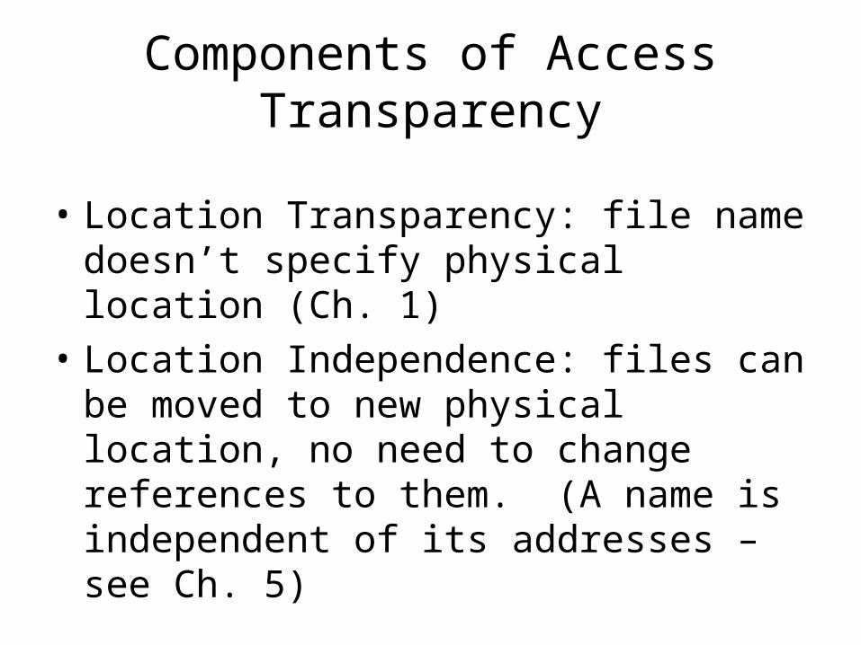
Components of Access Transparency
• Location Transparency: file name doesn’t specify physical location (Ch. 1)
• Location Independence: files can be moved to new physical location, no need to change references to them. (A name is independent of its addresses – see Ch. 5)
Goals
• Availability: files should be easily and quickly accessible.
• The number of users, system failures, or other consequences of distribution shouldn’t compromise the availability.
• Addressed mainly through replication.
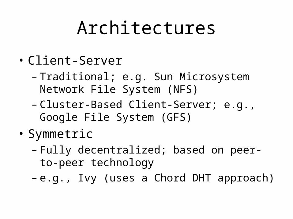
Architectures
• Client-Server– Traditional; e.g. Sun Microsystem Network
File System (NFS)– Cluster-Based Client-Server; e.g., Google File
System (GFS)
• Symmetric– Fully decentralized; based on peer-to-peer
technology– e.g., Ivy (uses a Chord DHT approach)
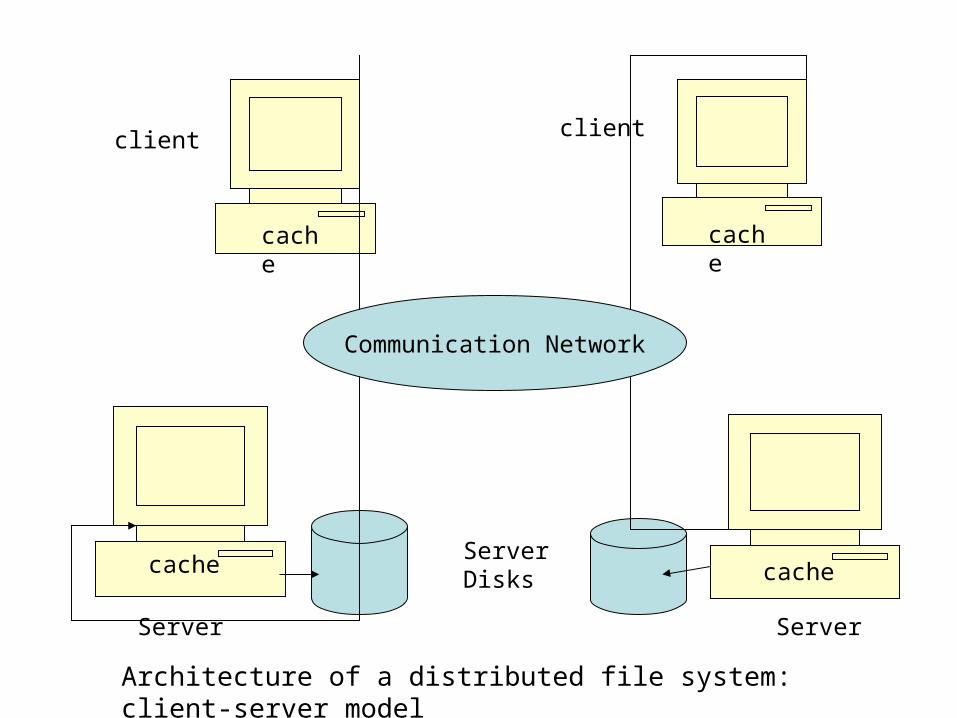
Client-Server Architecture
• One or more machines (file servers) manage the file system.
• Files are stored on disks at the servers
• Requests for file operations are made from clients to the servers.
• Client-server systems centralize storage and management; P2P systems decentralize it.
Communication Network
cache
cache
cache
cache
Server Server
ServerDisks
client client
Architecture of a distributed file system: client-server model
Sun’s Network File System
• Sun’s NFS for many years was the most widely used distributed file system.– NFSv3: version three, used for many years– NFSv4: introduced ~2003
• Has some major differences from the earlier versions
Overview• NFS goals:
– Each file server presents a standard view of its local file system
– transparent access to remote files– compatibility with multiple operating systems and
platforms.– easy crash recovery at server
• Originally UNIX based; now available for most operating systems.
• NFS communication protocols lets processes running in different environments share a file system.
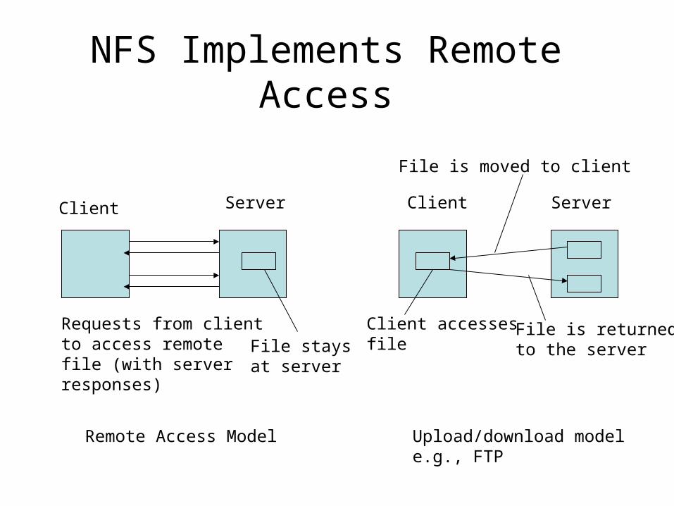
NFS Implements Remote Access
Client Server Client Server
Requests from clientto access remotefile (with serverresponses)
File staysat server
File is moved to client
Client accessesfile
File is returnedto the server
Remote Access Model Upload/download modele.g., FTP
Access Models
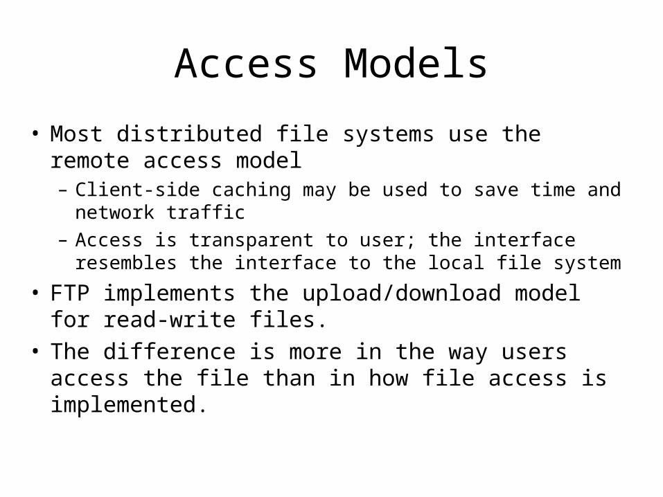
• Most distributed file systems use the remote access model– Client-side caching may be used to save time and
network traffic– Access is transparent to user; the interface resembles
the interface to the local file system
• FTP implements the upload/download model for read-write files.
• The difference is more in the way users access the file than in how file access is implemented.
System Architecture
• Virtual File System (VFS) acts as an interface between the operating system’s system call layer and all file systems on a node.
• The user interface to NFS is the same as the interface to local file systems. The calls go to the VFS layer, which passes them either to a local file system or to the NFS client
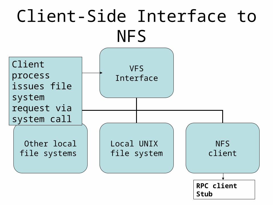
Client-Side Interface to NFS
VFSInterface
Other localfile systems
Local UNIX file system
NFSclient
Client processissues file system request via system call
RPC client Stub
NFS Client/Server Communication
• The NFS client communicates with the server using RPCs– File system operations are implemented as remote
procedure calls
• At the server: an RPC server stub receives the request, “un-marshalls” the parameters & passes them to the NFS server, which creates a request to the server’s VFS layer.
• The VFS layer performs the operation on the local file system and the results are passed back to the client.
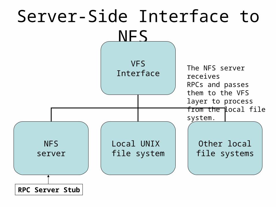
Server-Side Interface to NFS
VFSInterface
NFSserver
Local UNIX file system
Other localfile systems
The NFS server receivesRPCs and passes them to the VFS layer to process from the local file system.
RPC Server Stub
NFS as a Stateless Server
• NFS servers historically did not retain any information about past requests.
• Consequence: crashes weren’t too painful– If server crashed, it had no tables to rebuild – just
reboot and go• Disadvantage: client has to maintain all state
information; messages are longer than they would be otherwise.
• Recent version (NFS version 4) is stateful – for example, file locking is supported.
File System Model
• NFS implements a file system model that is almost identical to a UNIX system.– Files are structured as a sequence of bytes– File system is hierarchically structured– Supports hard links and symbolic links– Implements most file operations that UNIX
supports• Some differences between NFSv3 and NFSv4• See Figure 11-3, page 495
File Create/Open/Close
• Create: v3 Yes, v4 No;Open: v3 No, v4 Yes;v4 creates a new file if an open operation is executed on a non-existent file
• Close: v3 No and v4 Yes
• Rationale: v3 was stateless; didn’t keep information about open files.
Cluster-based or Clustered File System
• A distributed file system that consists of several servers that share the responsibilities of the system, as opposed to a single server (possibly replicated).
• The design decisions for a cluster-based systems are mostly related to how the data is distributed across the cluster and how it is managed.
Cluster-Based DFS
• Some cluster-based systems organize the clusters in an application specific manner
• For file systems used primarily for parallel applications, the data in a file might be striped across several servers so it can be read in parallel.
• Or, it might make more sense to partition the file system itself – some portion of the total number of files are stored on each server.
• For systems that process huge numbers of requests; e.g., large data centers, reliability and management issues take precedence.– e.g., Google File System
Google File System (GFS)
• GFS uses a cluster-based approach implemented on ordinary commodity Linux boxes (not high-end servers).
• GFS stores a huge number of files (built by its Web Crawlers) on thousands of computers – stores terabytes of data– The system must be designed to resist node
failure; because of the large number of machines it is certain that failures occur on a regular basis.
The Google File System
• File characteristics– Very large, multiple gigabytes– Files are updated by appending new entries
to the end (faster than overwriting existing data)
– Files are virtually never modified (other than by appends) and virtually never deleted.
• Servers fail on a regular basis, just because there are so many of them.
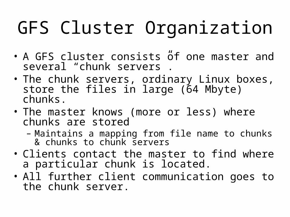
GFS Cluster Organization
• A GFS cluster consists of one master and several “chunk servers”.
• The chunk servers, ordinary Linux boxes, store the files in large (64 Mbyte) chunks.
• The master knows (more or less) where chunks are stored– Maintains a mapping from file name to chunks & chunks
to chunk servers• Clients contact the master to find where a
particular chunk is located.• All further client communication goes to the chunk
server.
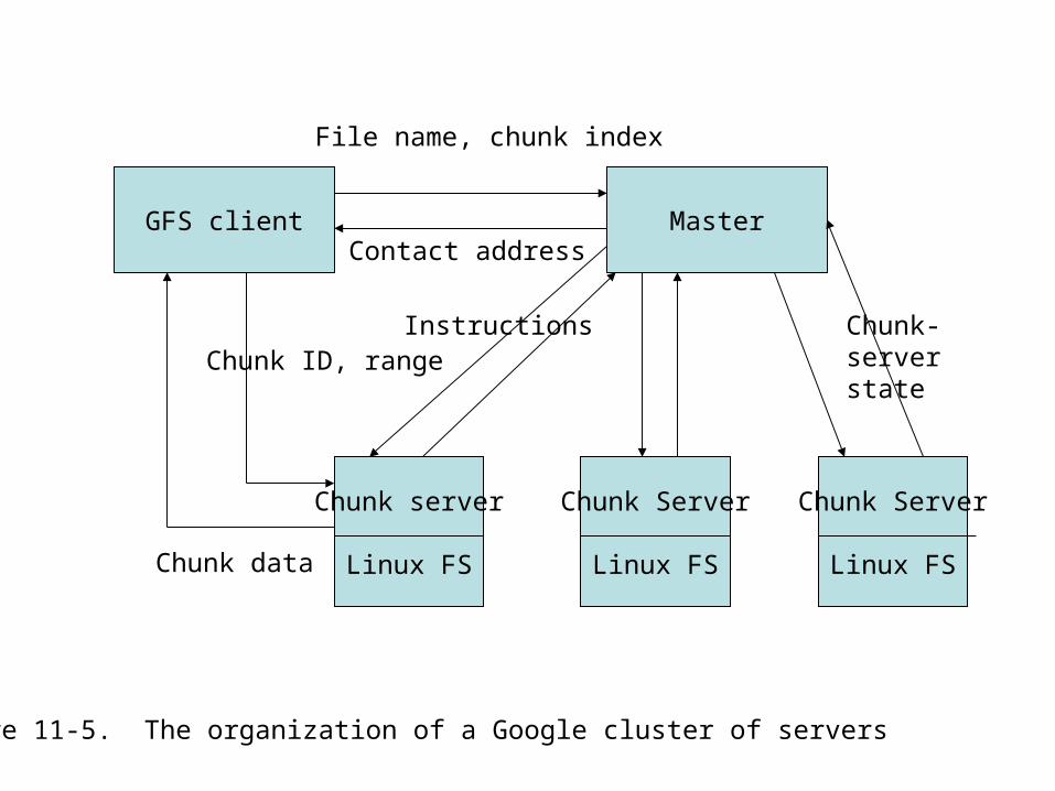
GFS client Master
Chunk server
Linux FS
Chunk Server
Linux FS
Chunk Server
Linux FS
File name, chunk index
Contact address
Instructions Chunk-server stateChunk ID, range
Chunk data
Figure 11-5. The organization of a Google cluster of servers
GFS
• Chunks are replicated for fault tolerance, using a primary/backup scheme.
• Periodically the master polls all its chunk servers to find out which chunks each one stores– This means the master doesn’t need to know when
new servers come on board, when servers crash, etc.
• Polling occurs often enough to guarantee that master’s information is “good enough”.
Scalability in GFS
• Clients only contact the master to get metadata, so it isn’t a bottleneck.
• Updates are performed by having a client update the nearest server which pushes the updates to one of the backups, which in turn sends it on to the next and so on.– Updates aren’t committed until all replicas are
complete.• Information for mapping file names to contact
addresses is efficiently organized & stored (mostly) in the master’s memory.– Access time is optimized due to infrequent disk
accesses.
Symmetric File Systems
Peer-to-Peer
Symmetric Architectures
• Fully distributed (decentralized) file systems do not distinguish between client machines and servers.
• Most proposed systems are based on a distributed hash table (DHT) approach for data distribution across nodes.
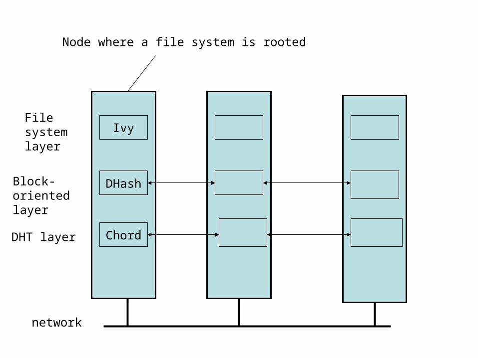
• The Ivy system is typical. It has a 3-layer structure.

Ivy System Structure
• The DHT layer implements a Chord scheme for mapping keys (which represent objects to be stored) to nodes.
• The DHash layer is a block-storage layer– Blocks = logical file blocks– Different blocks are stored in different
locations
• The top, or file system layer, implements an NFS-like file system.
Characteristics
• File data and meta-data stored as blocks in a DHash P2P system
• Blocks are distributed and replicated across multiple sites – increased availability.
• Ivy is a read-write file system. Writing introduces consistency issues (of data and meta-data)
Characteristics
• Presents an NFS-like interface and semantics
• Performance: 2X-3X slower than NFS
• Potentially more available because of distributed nature
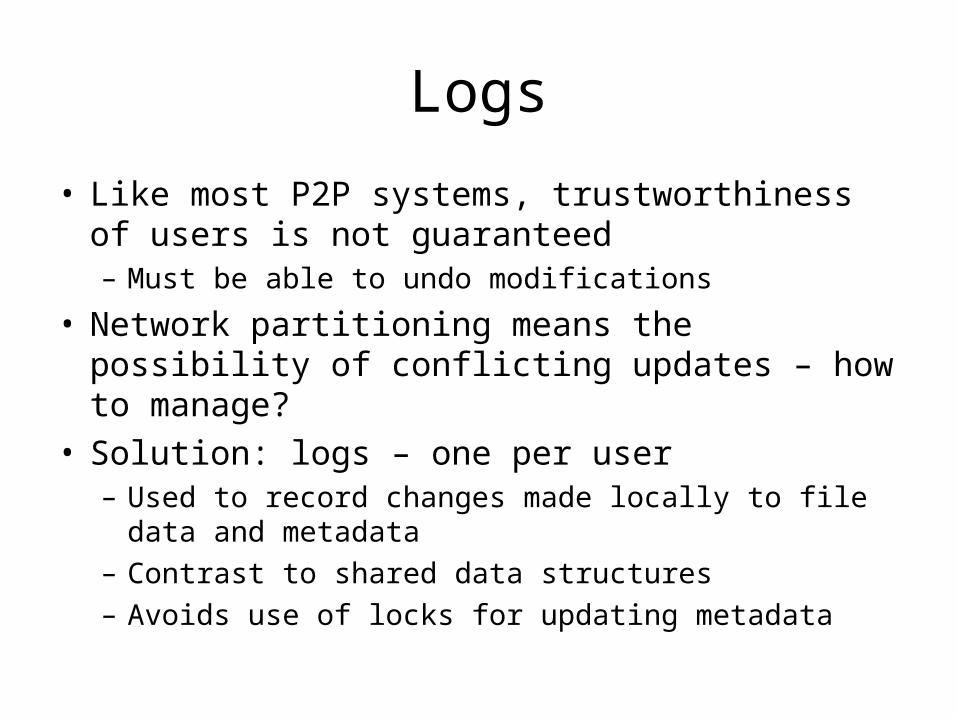
Logs
• Like most P2P systems, trustworthiness of users is not guaranteed– Must be able to undo modifications
• Network partitioning means the possibility of conflicting updates – how to manage?
• Solution: logs – one per user– Used to record changes made locally to file data and
metadata– Contrast to shared data structures– Avoids use of locks for updating metadata
Ivy
DHash
Chord
network
File system layer
Block-oriented layer
DHT layer
Node where a file system is rooted
DHash Layer
• Manages data blocks (of a file)• Stored as content-hash block or public-key block• Content-hash blocks
– Compute the secure hash of this block to get the key– Clients must know the key to look up a block– When the block is returned to a client, compute its
hash to verify that this is the correct (uncorrupted) block.
DHash Layer – Public Key Blocks
• “A public key block requires the block’s key to be a public key, and the value to be signed using the private key.”
• Users can look up a block without the private key, but cannot change data unless they have the private key.
• Ivy layer verifies all the data DHash returns and is able to protect against malicious or corrupted data.
DHash Layer
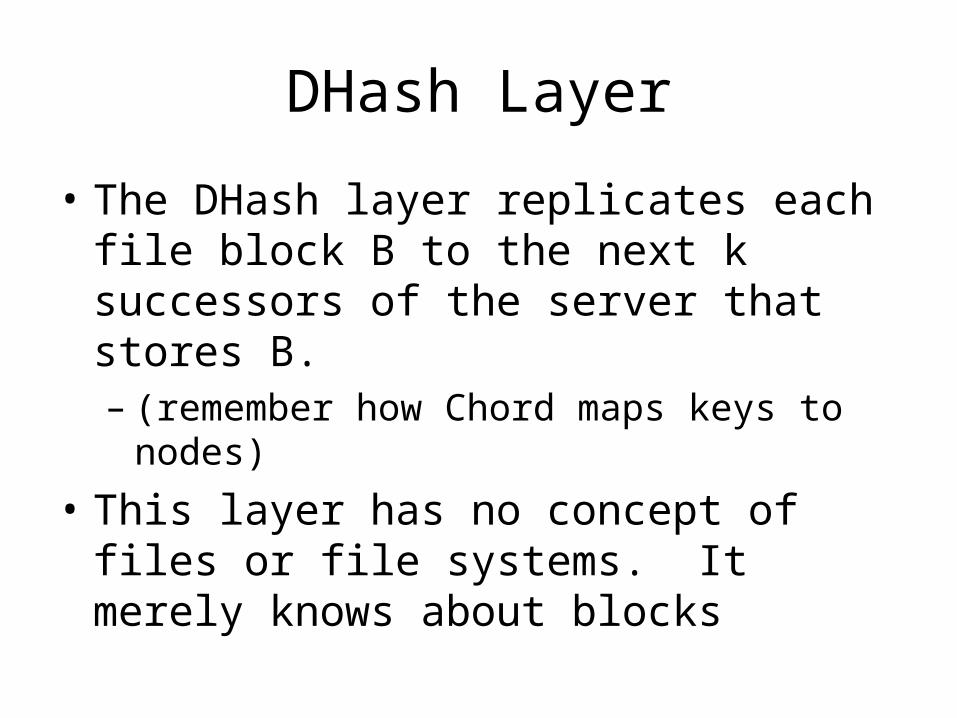
• The DHash layer replicates each file block B to the next k successors of the server that stores B.– (remember how Chord maps keys to nodes)
• This layer has no concept of files or file systems. It merely knows about blocks
Ivy – the File System Layer
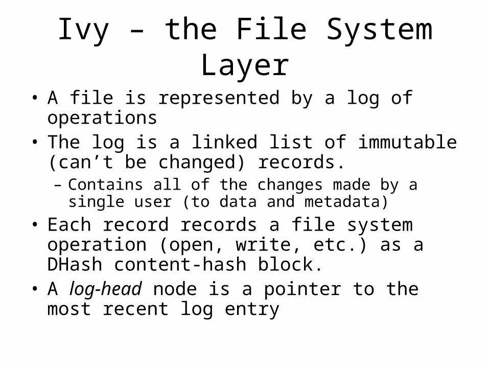
• A file is represented by a log of operations• The log is a linked list of immutable (can’t be
changed) records.– Contains all of the changes made by a single user (to
data and metadata)
• Each record records a file system operation (open, write, etc.) as a DHash content-hash block.
• A log-head node is a pointer to the most recent log entry
Using Logs
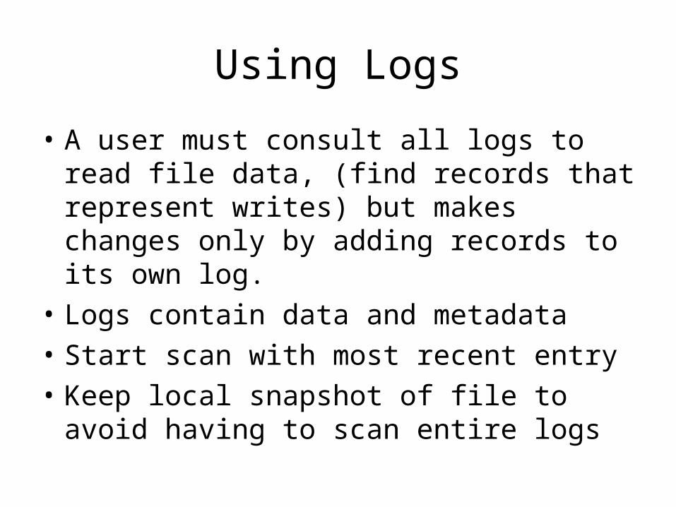
• A user must consult all logs to read file data, (find records that represent writes) but makes changes only by adding records to its own log.
• Logs contain data and metadata
• Start scan with most recent entry
• Keep local snapshot of file to avoid having to scan entire logs
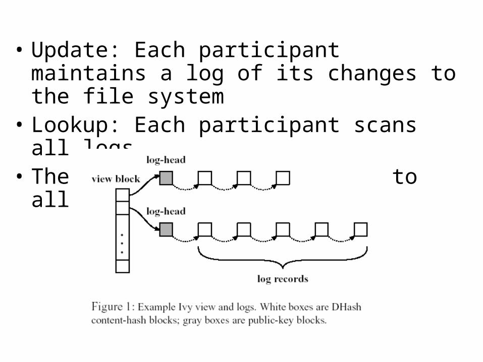
• Update: Each participant maintains a log of its changes to the file system
• Lookup: Each participant scans all logs• The view-block has pointers to all log-heads
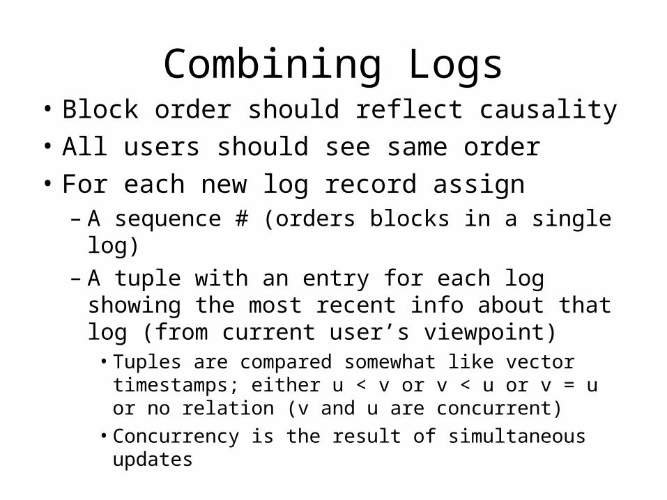
Combining Logs• Block order should reflect causality
• All users should see same order
• For each new log record assign– A sequence # (orders blocks in a single log)– A tuple with an entry for each log showing the
most recent info about that log (from current user’s viewpoint)
• Tuples are compared somewhat like vector timestamps; either u < v or v < u or v = u or no relation (v and u are concurrent)
• Concurrency is the result of simultaneous updates
Where We Are
• DFS Architectures – finished– Client-server– Cluster-based– Symmetric
• Processes
• Communication
• Naming
End of Part 1
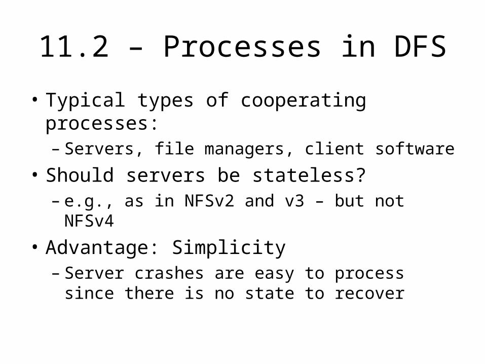
11.2 – Processes in DFS
• Typical types of cooperating processes:– Servers, file managers, client software
• Should servers be stateless?– e.g., as in NFSv2 and v3 – but not NFSv4
• Advantage: Simplicity– Server crashes are easy to process since
there is no state to recover
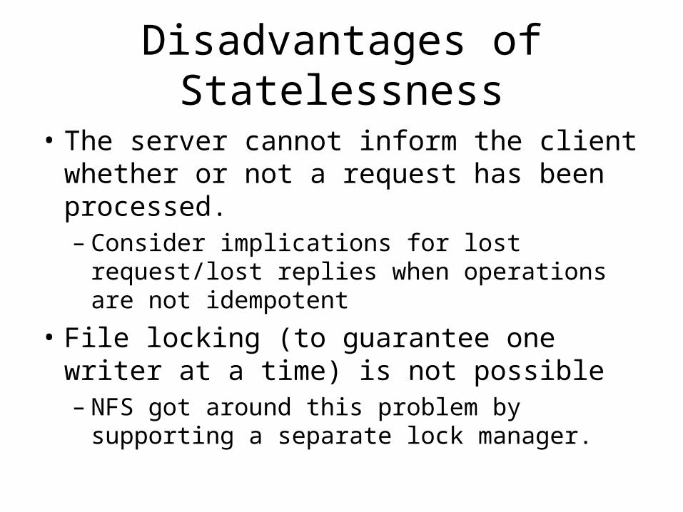
Disadvantages of Statelessness
• The server cannot inform the client whether or not a request has been processed.– Consider implications for lost request/lost
replies when operations are not idempotent
• File locking (to guarantee one writer at a time) is not possible– NFS got around this problem by supporting a
separate lock manager.
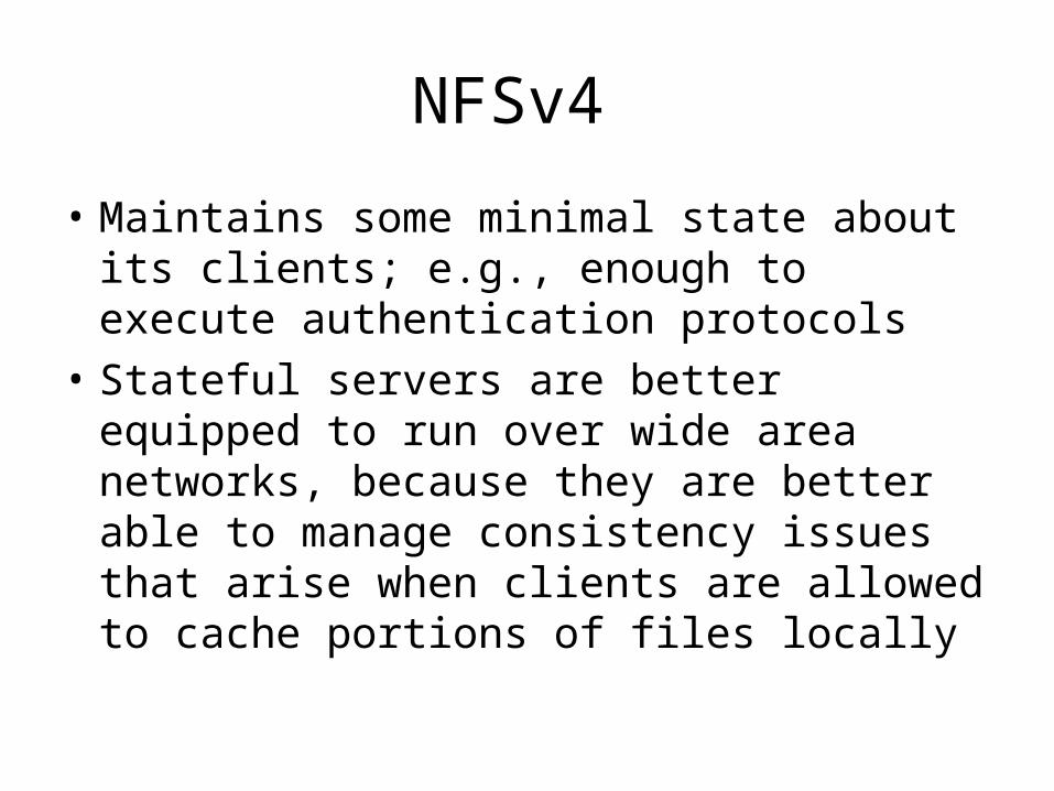
NFSv4
• Maintains some minimal state about its clients; e.g., enough to execute authentication protocols
• Stateful servers are better equipped to run over wide area networks, because they are better able to manage consistency issues that arise when clients are allowed to cache portions of files locally
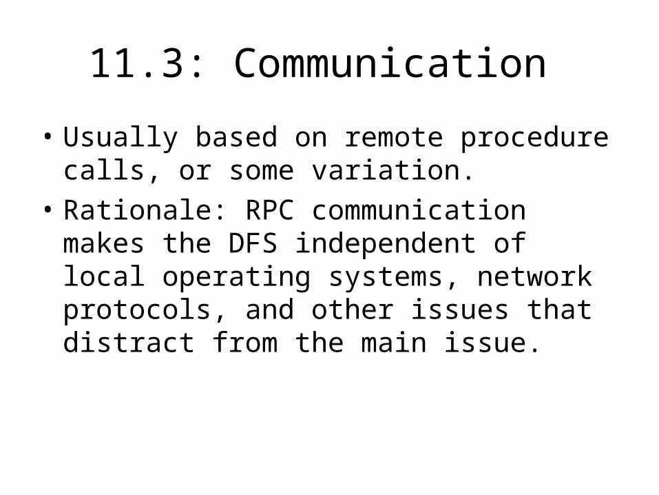
11.3: Communication
• Usually based on remote procedure calls, or some variation.
• Rationale: RPC communication makes the DFS independent of local operating systems, network protocols, and other issues that distract from the main issue.
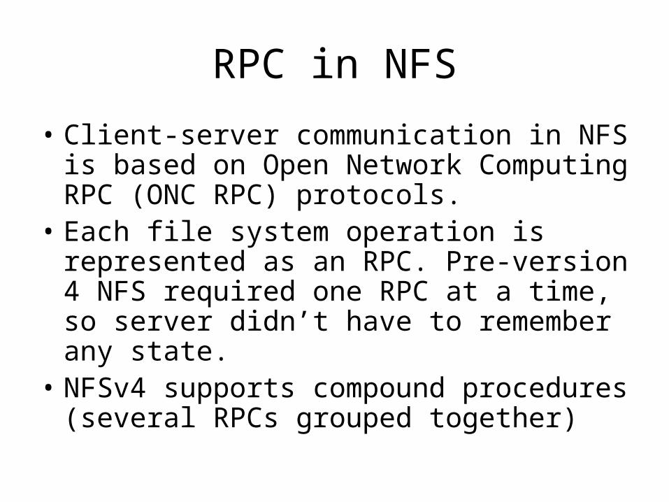
RPC in NFS
• Client-server communication in NFS is based on Open Network Computing RPC (ONC RPC) protocols.
• Each file system operation is represented as an RPC. Pre-version 4 NFS required one RPC at a time, so server didn’t have to remember any state.
• NFSv4 supports compound procedures (several RPCs grouped together)
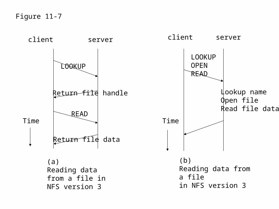
client server client server
LOOKUP
Return file handle
READ
Return file data
LOOKUPOPENREAD
Lookup nameOpen fileRead file data
Time Time
(a)Reading data from a file in NFS version 3
(b)Reading data from a file in NFS version 3
Figure 11-7
Compound Procedures
• Reduce amount of network traffic.
• What if an operation fails?– The remainder of the operations are not
attempted– Any information found so far is returned to the
client.
11.4 – Naming
• NFS is used as a typical example of naming in a DFS.
• Virtually all support a hierarchical namespace organization.
• NFS naming model strives to provide transparent client access to remote file systems.
Goal
• Network (Access)Transparency
– Users should be able to access files over a network as easily as if the files were stored locally.
– Users should not have to know the location of a file to access it.
• Transparency can be addressed through naming and file mounting mechanisms
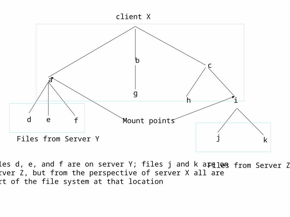
Mounting
• Servers export file systems; i.e, make them available to clients
• Client machines can attach a remote FS (directory or subdirectory) to the local FS at any point in its directory hierarchy.
• When a FS is mounted, the client can reference files by the local path name – no reference to remote host location, although files remain physically located at the remote site.
• Mount tables keep track of the actual physical location of the files.
client X
a
bc
d e f
gh i
j kFiles from Server Y
Files from Server Z
Mount points
Files d, e, and f are on server Y; files j and k are onserver Z, but from the perspective of server X all are part of the file system at that location
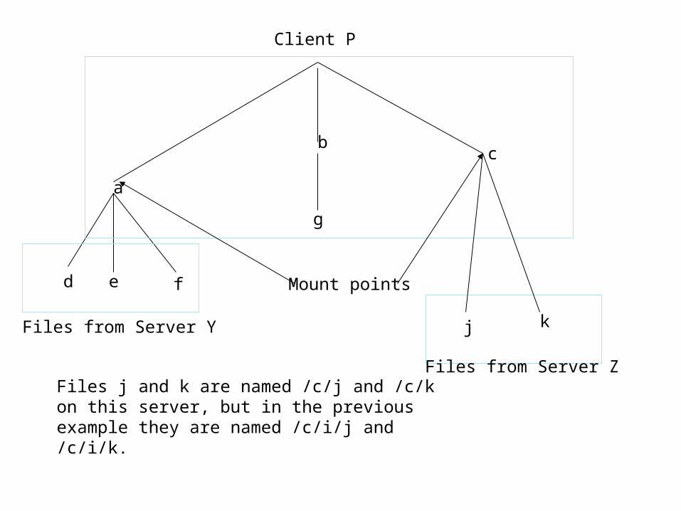
Name Space Uniqueness
• In principle,users are allowed to mount files anywhere in their local directory system.– If this is permitted, then two users may have
different names for the same file– See Figure 11-11 (page 507) in the textbook
Client P
a
bc
d e f
g
j kFiles from Server Y
Files from Server Z
Mount points
Files j and k are named /c/j and /c/k on this server, but in the previous example they are named /c/i/j and /c/i/k.
Namespaces
• The usual approach to file sharing is to partially standardize namespaces
• Shared files can be mounted in an agreed-upon directory, so all sharers can have the same file names.
File Handles
• A file handle is a reference to a file that is created by the server when the file is created.– It is independent of the actual file name– It is not known to the client (although the
client must know the size)– It is used by the file system for all internal
references to the file.
Benefits of File Handles
• There is a uniform format for the file identifier inside the file system (128 bytes, in NFSv4)
• Clients can store the handle locally after an initial reference and avoid the lookup process on subsequent file operations

QUESTIONS?