Embed Size (px)
Citation preview

Distributed Antenna Systems: Open Architecture for Future
Wireless Communications
Editors
August 10, 2006

ii
Contents
1 Cross Layer Design for Wireless Sensor Networks with Virtual MIMO 1
1.1 Introduction . . . . . . . . . . . . . . . . . . . . . . . . . . . . . . . . . . . . 2
1.2 Related Work . . . . . . . . . . . . . . . . . . . . . . . . . . . . . . . . . . . 5
1.2.1 The Related Work in The Virtual MIMO Design in WSN . . . . . . . 5
1.2.2 The Related Work in The Reliable Data Transfer in WSN . . . . . . 6
1.2.3 The Related Work in The QoS Provisioning in WSN . . . . . . . . . 7
1.3 Cross Layer Design Based on The Virtual MIMO Scheme . . . . . . . . . . . 8
1.3.1 System Architecture . . . . . . . . . . . . . . . . . . . . . . . . . . . 8
1.3.2 Single-Hop Transmission Scheme Design . . . . . . . . . . . . . . . . 9
1.3.3 End-to-end Transmission Scheme Design . . . . . . . . . . . . . . . . 20
1.4 Theoretical Analysis of The Cross Layer Design . . . . . . . . . . . . . . . . 23
1.4.1 Energy Consumption and End-to-end QoS Performance Analysis . . . 23
1.4.2 Parameters Optimization . . . . . . . . . . . . . . . . . . . . . . . . . 25
1.5 Simulation and Numerical Results . . . . . . . . . . . . . . . . . . . . . . . . 27
i

ii CONTENTS
1.5.1 Energy Saving Performance of The Cross Layer Design . . . . . . . . 27
1.5.2 QoS Provisioning Performance of The Cross Layer Design . . . . . . 30
1.6 Conclusion and Open Issues . . . . . . . . . . . . . . . . . . . . . . . . . . . 32
Chapter 1
Cross Layer Design for Wireless
Sensor Networks with Virtual MIMO
Yong Yuan, Min Chen
Huazhong University of Science and Technology
University of British Columbia
Energy efficiency, reliability and QoS provisioning are the main concerns in the design of
wireless sensor networks (WSNs) to support the diverse applications. However, the design
issues of energy efficiency, reliability and QoS provisioning in WSN are multifaceted problems
jointly influenced by the physical, MAC, network and transport layers. Recently, some
virtual MIMO schemes based on single antenna sensors have been proposed and studied to
improve the energy efficiency of the wireless communication schemes. Though the initial
proposal of the virtual MIMO schemes focuses on the physical layer design, the adoption
of this novel technology also provides a wider design space for the schemes in the upper
layers. In this chapter, a cross layer design scheme based on virtual MIMO scheme is
proposed for WSN. In the design, the sensor nodes form a cooperative node set to transmit
data according to the virtual MIMO scheme. Then, the virtual MIMO scheme, multi-hop
routing scheme and HARQ-based retransmission schemes are jointly designed to improve
1
2CHAPTER 1. CROSS LAYER DESIGN FOR WIRELESS SENSOR NETWORKS WITH VIRTUAL MIMO
the performance of energy efficiency, reliability and QoS guarantees in terms of delay and
throughput. Based on the design, we also developed the model for end-to-end QoS and overall
energy consumption of the design in terms of the BER performance in each link. Then, the
energy saving performance and QoS provisioning ability of the scheme are demonstrated
through comprehensive simulations. At last, the chapter is concluded by identifying some
open research issues on this topic. 1
1.1 Introduction
Recent years have witnessed a growing interest in deploying a sheer number of micro-sensors
that collaborate in a distributed manner on data gathering and processing. Sensors are
expected to be inexpensive and can be deployed in a large number to harsh environments,
which implies that sensors are typically operating unattended. In addition, sensor networks
are also subject to high fault rate; connectivity between nodes can be lost due to environ-
mental noise and obstacles; nodes may die due to battery depletion, environmental changes
or malicious destruction. In such an environment, reliable and energy-efficient data delivery
is crucial because sensor nodes operate with limited battery power and an error-prone wire-
less channel. On the other hand, wireless sensor networks are expected to be used in a wide
range of applications, such as target tracking, habitat sensing and fire detection, etc. The
data gathering in such applications are often required to be timely. For example, when a
target enters an area of interest, it may be critical to reduce the delay of sensor reports. If
the reported event is not received by the sink node within a certain deadline, reported infor-
mation may be obsolete and useless. Therefore, end-to-end QoS provisioning is important
for such applications in WSN. In addition, different applications have different end-to-end
transmission quality requirements in terms of latency and throughput.
Due to these characteristics, energy efficiency, reliability and end-to-end QoS provisioning
should be jointly considered in the design of WSN. However, these design issues are multi-
facted problems influenced by the physical, MAC, network and transport layers. The energy
1 c©IEEE, 2006. This is a major revision of the work published in IEEE Transactions on Vehicular Technology, Volume 53,Issue 3 (May 2006)

1.1. INTRODUCTION 3
efficient wireless communication schemes, routing schemes, power conservation schemes and
reliable transportation schemes should be jointly considered to maximize the performance
in terms of energy efficiency, reliability and end-to-end QoS.
Among all the related schemes, the energy efficiency is deemed as a necessity for the
wireless communication scheme in WSN, since wireless communication has been identified
as the dominant power-consuming operation. In addition, the hash working environments,
channel fading, interference and radio irregularity further pose challenges on the design of
energy efficient wireless communication scheme for WSN. In the wireless communication
schemes, MIMO techniques have been studied intensively in recent years [1, 2] due to their
effectiveness for enhancing reliability, energy and bandwidth efficiency and the ability to
deal with fading phenomena. The characteristics of the MIMO techniques makes them
desirable for WSN. However, it is difficult to directly apply MIMO techniques in the low-
cost small-sized sensors. Some virtual MIMO schemes based on single antenna sensors have
been proposed and studied to improve energy saving and spectral efficiency [3, 4, 5, 6, 7, 8,
9, 10, 11, 13]. In such schemes, multiple individual single-antenna nodes will form a virtual
antenna array, and each node will be viewed as an antenna in the array. These nodes will
cooperate in the MIMO manner on information transmission and/or reception. Based on
the virtual MIMO design, the advantages of the MIMO scheme will make the physical layer
of WSN more reliable and energy efficient. On the other hand, the adoption of the virtual
MIMO scheme in the physical layer also opens a wider design and optimization space for
the schemes in the upper layers, such as the retransmission, distributed operation, multi-hop
routing and QoS provisioning schemes.
In this chapter, the state-of-the-art of the related schemes are summarized and compared
including the virtual MIMO schemes, reliable data transmission schemes and QoS provision-
ing schemes. Then, a cross layer design based on the virtual MIMO scheme is proposed to
improve the performance of WSN in terms of energy efficiency, QoS provisioning and reli-
ability. In the cross layer design, radio irregularity of wireless communications, multi-hop
routing, retransmissions and end-to-end QoS provisioning are jointly considered with the
virtual MIMO scheme.
4CHAPTER 1. CROSS LAYER DESIGN FOR WIRELESS SENSOR NETWORKS WITH VIRTUAL MIMO
Firstly, we design a single-hop transmission scheme, where an adaptive cooperative nodes
selection strategy is proposed to find the optimal cooperative nodes set to minimize the
energy cost. In order to improve the reliability of the data transmission, three HARQ-based
retransmission schemes are considered to incorporate into the virtual MIMO scheme. The
average energy consumption for a successful packet transmission by the virtual MIMO scheme
under three retransmission schemes are analyzed and compared. Then the retransmission
scheme by hop-by-hop recovery is incorporated into the virtual MIMO scheme due to its
efficiency. In analysis, the overall energy consumption for a successful packet transmission is
found to depend on the average retransmission times and the energy consumption per time
transmission, which can be traded off by the BER performance in transmission. Therefore,
an optimal set of transmission parameters, including the BER performance, the number of
cooperative nodes and the number of hops, can be found to minimize the overall energy
consumption.
Based on the single-hop transmission scheme, an end-to-end transmission scheme is de-
signed. In order to simplify the procedure of forming cooperative nodes set for the virtual
MIMO scheme, the concept of clustering is adopted to organize the sensor nodes into multi-
ple clusters and form the cluster heads as a multi-hop backbone. During the transmission,
each cluster head will transmit data to its’ neighbor cluster through the cooperative nodes
set by the virtual MIMO scheme. The energy cost for the virtual MIMO communication will
be defined as the routing cost between two cluster heads in the multi-hop backbone. Then
the shortest path tree (SPT) will be constructed by finding the path with minimum overall
energy cost for each cluster head to transmit data to the sink. On the other hand, since
the retransmission scheme is considered in each single-hop transmission, the throughput and
energy consumption for packet transmission on each link in the SPT will be dependent on
the BER performance. Accordingly, the queuing latency and throughput on the link will
also be dependent on the BER performance, which in turn impacts the end-to-end latency
and throughput. Therefore the low-level communication parameter, BER performance Pb
will determine the high-level QoS performance in terms of end-to-end latency and through-
put. Based on this observation, the end-to-end QoS performance and the overall energy
consumption are modelled by the queuing theory in terms of the BER performance of each
link in the SPT. The search for the optimal BER performance for each link is modelled as

1.2. RELATED WORK 5
a nonlinear constrained optimization problem to minimize the overall energy consumption
without violating the end-to-end QoS requirements. The particle swarm algorithm (PSO) is
employed in this chapter to solve the problem.
The remainder of the chapter is organized as follows. Section 1.2 describes the related
work of the design. In Section 1.3, the proposed cross layer design scheme based on the
virtual MIMO is discussed in detail. Then, in Section 1.4, the energy consumption and QoS
performance of the scheme are analyzed and an optimization model is developed to find the
optimal parameters. Section 1.5 presents the simulation results. Then, Section 1.6 provides
some conclusions and points out aspects that will be subject of future research.
1.2 Related Work
Our work is closely related to the virtual MIMO scheme design in WSN, the reliable data
transfer in WSN, and end-to-end QoS provisioning in WSN. We will give a brief review of
the work in these three aspects.
1.2.1 The Related Work in The Virtual MIMO Design in WSN
The basic idea of the virtual MIMO scheme is extended from the virtual antenna arrays
(VAA) in the design of ad-hoc oriented 4G networks [3, 4]. M.Dohler proposed the system
capacity analysis, resource allocation strategy and related protocols about the application of
VAA to cellular networks in [3, 4]. As for the work of virtual MIMO scheme design in WSN,
Xiaohua Li [5] proposed a virtual MIMO scheme using two transmitting sensors and space-
time block code (STBC) to provide transmission diversity in WSN with neither antenna-
array nor transmission synchronization. The author argued that according to the scheme,
the full diversity and full rate are achieved which enhances power/bandwidth efficiency and
reliability. Xiaohua Li also extended the scheme for using any number of transmission
sensors by the distributed STBC in [6, 7]. In [8], Xiaohua Li also proposed a blind channel
estimation and equalization scheme in such virtual MIMO scheme. B. Azimi-sadjadi, et al, [9]
6CHAPTER 1. CROSS LAYER DESIGN FOR WIRELESS SENSOR NETWORKS WITH VIRTUAL MIMO
proposed a method in CDMA wireless multi-hop networks which groups transmission nodes
into cooperative clusters to reduce the total power expenditure of transmitting nodes. S. Cui
[10] analyzed a cooperative MIMO scheme with Alamouti code for single-hop transmission
in WSN. S. K. Jayaweera considered the training overheads of such scheme in [11], and found
that the training overheads can be modelled as proportional to the number of cooperative
nodes. S. K. Jayaweera also proposed a virtual MIMO communication architecture based
on the VBLAST processing [12]. J. N. Laneman also did the research work on the system
capacity analysis of the virtual MIMO scheme in [13]. S. Jagannathan et al [14] investigated
the effect of time synchronization errors on the performance of the cooperative MISO systems,
and concluded that the cooperative MISO scheme has a good tolerance of up to 10% clock
jitter. The previous work of virtual MIMO scheme focus on the MIMO schemes design in
WSN and the analysis of system capacity and energy consumption. However, the previous
work did not consider the impacts of the specific issues of multi-hop networking, reliable
transmission and end-to-end QoS provisioning on the virtual MIMO scheme, which may
result in sub-optimal system performances in terms of energy efficiency, reliability and end-
to-end QoS. Our work differs mainly with the previous work in that the cross layer design
of the virtual MIMO scheme is considered, which integrates the virtual MIMO scheme with
the multi-hop routing scheme, retransmission scheme and end-to-end QoS provisioning.
1.2.2 The Related Work in The Reliable Data Transfer in WSN
As for the aspect of reliable data transfer in WSN, since the pioneer work on reliable transport
protocol, PSFQ, presented in [16], there are increasing research efforts on studying the issue
of reliable data transfer in WSN [16, 17, 18, 19, 20, 21]. PSFQ works by distributing data from
source nodes in a relatively slow pace and allowing nodes experienced data loss to recover
any missing segments from immediate neighbors aggressively. PSFQ employs hop by hop
recovery instead of end to end recovery. In [17], the authors proposed RMST, a transport
protocol that provides guaranteed delivery for applications requiring them. RMST is a
selective NACK-based protocol that can be configured for in-networking caching and repair.
An event-to-sink reliable transport (ESRT) protocol is presented in [18]. In ESRT, the sink
adaptively achieves the expected event reliability by controlling the reporting frequency of
1.2. RELATED WORK 7
the source nodes. In [19], a protocol called ReInForM is proposed to deliver packets at desired
reliability by sending multiple copies of each packet along multiple paths from sources to
sink. Several acknowledgement based end-to-end reliable event transfer schemes are proposed
to achieve various levels of reliability in [20]. C. Taddia [21] also proposed and compared
four information delivery methods by different retransmission schemes in WSN. End-to-end
and/or hop-by-hop recovery, forward error correction codes and multi-path forwarding are
the major approaches to achieve the desired reliability by previous work. However, the
reliable data transfer in WSN is a multifaceted problem influenced by multiple protocol
layers. In our work, the retransmission schemes in MAC layer and the virtual MIMO scheme
in the physical layer are jointly designed to improve the system performance in terms of
energy efficiency and data reliability.
1.2.3 The Related Work in The QoS Provisioning in WSN
End-to-end QoS provisioning in WSN has so many applications, such as real-time target
tracking in battle environments, emergent event triggering in monitoring applications, etc.
The applications often have the QoS requirements in terms of end-to-end latency and end-
to-end throughput. There are increasing research efforts on studying the issue of QoS pro-
visioning in WSN. Sequential Assignment Routing (SAR) is the first routing protocol for
WSN that includes a notion of QoS in its routing decisions [22]. SPEED [23] is an adaptive
real-time routing protocol that aims to reduce the end-to-end deadline miss ratio in WSN.
K.Akkaya proposed an energy-aware QoS routing protocol to support both best effort and
real-time traffic at the same time [24] . The purpose is to meet the end-to-end delay con-
straint of the real-time traffic and maximize the throughput of the best effort traffic at the
same time. K.Akkaya also used a Weighted Fair Queuing (WFQ) based packet scheduling to
achieve the end-to-end delay bound in [25]. We also proposed an integrated energy and QoS
aware wireless transmission scheme for WSN [26], in which the QoS requirements in the ap-
plication layer, the modulation and transmission schemes in the data link layer and physical
layer are jointly optimized for end-to-end QoS provisioning. In this paper, we consider the
problem of energy aware QoS provisioning in another way, that is to model the end-to-end
QoS performance and overall energy consumption in terms of the BER performance of each
8CHAPTER 1. CROSS LAYER DESIGN FOR WIRELESS SENSOR NETWORKS WITH VIRTUAL MIMO
link according to the cross layer design of the multi-hop virtual MIMO transmission scheme.
Then, the search for the optimal BER performance of each link is modelled as a nonlinear
constrained optimization problem.
1.3 Cross Layer Design Based on The Virtual MIMO Scheme
In this section, we will describe the proposed cross layer design scheme based on virtual
MIMO in detail. First, the system architecture of the scheme is described. Then, the design
of the single-hop transmission is discussed. Based on the single-hop transmission scheme,
the end-to-end cross layer design is proposed.
1.3.1 System Architecture
The reference system architecture of the proposed cross layer design based on virtual MIMO
is demonstrated in Fig.1.1. In the proposed architecture, the data bits collected by multiple
source nodes will be transmitted to a remote sink by multiple hops. During the transmis-
sion, the sensor nodes will be organized into multiple clusters. The transmission in each
hop can be divided into two main operations. First, the cluster head will broadcast the
data bits to the cooperative nodes in the local cluster. We assume an AWGN channel with
squared power path loss in such transmission due to the short intra-cluster transmission
range. Then, the cooperative nodes will encode and transmit the data bits to the cluster
head in the next hop according to the orthogonal space-time block codes (STBC). For the
inter-cluster communications, we assume the transmission from each cooperative node ex-
periences frequency-nonselective and slow Rayleigh fading. Furthermore, the long distance
between any two nodes in the network with respect to the wavelength gives rise to inde-
pendent fading coefficients for the cooperative nodes. The rationale behind such channel
assumptions is that the inter-cluster transmission distance is much larger than the intra-
cluster transmission distance and the transmission environments are more complex in the
inter-cluster communication. In the design, the distance between the source cluster to the
destination cluster is denoted as d, the number of hops is denoted as H, and the number of

1.3. CROSS LAYER DESIGN BASED ON THE VIRTUAL MIMO SCHEME 9
cooperative nodes in each single-hop transmission is denoted as J . Since BPSK can achieve
very close performance as the variable-rate modulation scheme with optimal rates, such as
MQAM [12], it is used as the modulation scheme, and the bandwidth is denoted as B.
The cluster containing the data source nodes is denoted as S, and the destination cluster
containing the sink is denoted as D.
1.3.2 Single-Hop Transmission Scheme Design
During each single hop transmission, several cooperative nodes will be chosen to commu-
nicate with the next cluster head by the virtual MIMO scheme. In order to maximize
the performance of single-hop communication between cluster heads, appropriate strategy
should be designed to choose the cooperative nodes. The strategy will be discussed in this
subsection. On the other hand, though the virtual MIMO scheme can obtain good BER per-
formance in an energy aware manner, the residual BER will also reduce the reliability of the
transmission. In order to improve the reliability further, the HARQ (Hybrid ARQ) scheme
in the data link layer is incorporated into the hop-by-hop and end-to-end transmission.
Strategy to Choose Cooperative Nodes
To maximize the performance of single-hop communications between cluster heads, an ap-
propriate strategy should be taken to choose the optimal cooperative nodes. Suppose that
the current cluster head will use J cooperative nodes to transmit data to its neighboring
cluster head t by the cooperative MIMO scheme.
Denote the distance between node j and its current cluster head by dj1. Also, denote
the distance and path loss for node j to communicate with cluster head t as djt and kjt,
respectively. For each single-hop transmission, the current cluster head will broadcast a
data packet to the cooperative nodes. Then, the cooperative nodes will encode and transmit
the transmission sequence according to the orthogonal space-time block codes (STBC) to t
toward the sink node. The energy consumption for these two operations in the single-hop
transmission will be modelled in the remainder of this section. Then, a novel strategy will

10CHAPTER 1. CROSS LAYER DESIGN FOR WIRELESS SENSOR NETWORKS WITH VIRTUAL MIMO
be developed to find the optimal set of cooperative nodes to minimize the overall energy
consumption.
Let Ebt(1) denote the energy consumption for the current cluster head to broadcast one
bit to the cooperative nodes. Ebt(1) can be broken down into two main components, the
transmit energy consumption, Ebtt(1), and the circuit energy consumption, Ebtc(1).
The BER performance for BPSK is Pb = Q(√
2r). Here r is the Signal to Noise Ra-
tio(SNR), which is defined as r = Pr
2Bσ2Nf[27] under the assumption of AWGN channel,
where Pr is the received signal power, σ2 is the power density of the AWGN and Nf is the
receiver noise figure.
In the high SNR regime, we can approximate the BER performance as Pb = e−r by
the Chernoff bound [27]. Hence, we obtain Pr = −2BNfσ2ln(Pb). Recall that B is the
bandwidth of BPSK modulation scheme. As the assumption of squared power path loss,
Ebt(1) can be modelled by Eqn.(1.1).
Ebt(1) = Ebtt(1) + Ebtc(1)
= −2(1 + α)Nfσ2ln(Pb)G1d
2maxMl + Pct+JPcr
B
(1.1)
where dmax is the maximum distance from the cooperative nodes to the cluster head, α is
the efficiency of the RF power amplifier, G1 is the gain factor at dmax = 1m, Ml is the link
margin, Nf is the receiver noise figure, Pct and Pcr are the circuit power consumption of the
transmitter and receiver respectively [10].
Let f1(Pb) = −2Nfσ2ln(Pb) and H(dmax) = G1Mld
2max. Then, Eqn.(1.1) can be rewritten
as Eqn.(1.2).
Ebt(1) = (1 + α)f1(Pb)H(dmax) + Pct+JPcr
B(1.2)
According to the definition, H(dj) can be measured as follows. Let the current cluster
head transmit a signal with transmit power Pout. Then, the power of the received signal at

1.3. CROSS LAYER DESIGN BASED ON THE VIRTUAL MIMO SCHEME 11
its cluster member, node j, is Pj1 = Pout
H(dj). Therefore, H(dj) can be measured as Eqn.(1.3).
H(dj) =Pout
Pj1
(1.3)
From Eqn.(1.2), we can find that the energy consumption in the intra-cluster transmission,
Ebt(1), can be reduced by choosing the nearer cooperative nodes.
To analyze the energy consumption for inter-cluster transmissions based on the cooper-
ative scheme, denoted by Ebt(2), we refine the results in [10]. In [10] an equal transmit
power allocation scheme is used as the channel state information (CSI) is not available at
the transmitter. If the average attenuation of the channel for each cooperative node pair
can be estimated, we can use an equal signal-to-noise (SNR) policy [28] to allocate the
transmit power for its effectiveness and simplicity. The average energy consumption per bit
transmission by BPSK in such a scheme can be approximated by Eqn.(1.4).
Ebt(2) = (1 + α)N0
P1J
b
J∑j=1
(4π)2dkjt
jt
GtGrλ2MlNf +
(JPct + Pcr)
B(1.4)
where N0 is the single-sided noise power spectral density, Pb is the desired BER performance,
Gt and Gr are the transmitter and receiver antenna gains respectively, and λ is the carrier
wavelength [10]. Eqn.(1.4) is extended from the result in [10] with the settings of different
distance and path loss for each cooperative node. The training overhead and transmission
rate are not considered in Eqn.(1.4), which will be considered in Section III.
The average attenuation of the channel for node j can be estimated as follows. Assume
the channel is symmetric, and t transmits a signal with transmit power Pout, then the power
of the received signal at node j, Pjt can be given by Eqn.(1.5).
Pjt = PoutGtGrλ
2
(4π)2dkjt
jt MlNf
=Pout
G(djt, kjt)(1.5)
12CHAPTER 1. CROSS LAYER DESIGN FOR WIRELESS SENSOR NETWORKS WITH VIRTUAL MIMO
where G(djt, kjt) = Pout
Pjt=
(4π)2dkjtjt
GtGrλ2 MlNf . Therefore, Eqn.(1.4) can be reformulated as
Ebt(2) = (1 + α) N0
P1J
b
∑Jj=1 G(djt, kjt) + (JPct+Pcr)
B
= (1 + α)f2(Pb)∑J
j=1 G(djt, kjt) + (JPct+Pcr)B
(1.6)
According to Eqn.(1.6), the transmit power of node j to communicate with cluster head
t can be described by Eqn.(1.7).
Poutjt = G(djt, kjt)N0B
P1J
b
(1.7)
The Strategy to Choose Cooperative Nodes
Based on Eqn.(1.2) and Eqn.(1.6), the overall energy consumption for the single-hop trans-
mission can be written as Eqn.(1.8).
Ebt = Ebt(1) + Ebt(2)
= (1 + α)[f1(Pb)H(dmax) + f2(Pb)∑J
j=1 G(djt, kjt)] + (J+1)(Pct+Pcr)B
(1.8)
From Eqn.(1.8), the energy consumption for the intra-cluster transmission, Ebt(1) and
inter-cluster transmission, Ebt(2) should be traded off to minimize Ebt. Ebt can be minimized
by choosing an appropriate set of cooperative nodes, which can minimize f1(Pb)H(dmax) +
f2(Pb)∑J
j=1 G(djt, kjt). In order to simplify the distributed strategy design, the cooperative
nodes should be chosen as the nodes whose f1(Pb)H(dj1) + f2(Pb)G(djt, kjt) are minimal. In
addition, in order to balance the energy consumption, the selection criterion is defined as
Eqn.(1.9).
βjt =Ej
f1(Pb)H(dj1) + f2(Pb)G(djt, kjt)(1.9)
where Ej is the remaining energy in the current round for node j. The rationale behind
definition of βjt is that the node, which has a good tradeoff between Ebt(1) and Ebt(2)
and has more remaining energy, should have a larger chance to be selected as cooperative
1.3. CROSS LAYER DESIGN BASED ON THE VIRTUAL MIMO SCHEME 13
node. Therefore, J nodes with maximum βjt will be chosen as the cooperative nodes to
communicate with cluster head t.
To Incorporate HARQ-based Retransmission Schemes
Though the virtual MIMO scheme can obtain good BER performance in an energy aware
manner, the residual BER will also reduce the reliability of the transmission. In order to
improve the reliability further, the HARQ scheme in the data link layer is incorporated
into the data transmission among cluster heads. HARQ is the widely accepted technique to
mitigate the link error. The basic idea of HARQ is to combine the ARQ schemes and FEC
to reduce the average retransmission times for a successful packet transmission. In HARQ
scheme, a FEC code is used to detect and correct the bit errors in the packet [29, 30]. If the
number of bit errors surpasses the error-correcting capability of the FEC code, a request is
sent to the sender to retransmit the packet. Currently, most HARQ schemes can be classified
into two types. In HARQ-I schemes, all the transmission attempts of a packet are identical
FEC codewords containing redundant bits for both error detection and error correction. The
error-correcting capability of the FEC part of the scheme can be designed so that most of the
erroneously received packets can be corrected, which reduces the number of retransmissions.
Generally speaking, the HARQ-I schemes are best suited for channel environments where the
level of noise and interference is fairly constant. On the other hand, the HARQ-II schemes
rely on the basic concept of incremental redundancy [31]. In the HARQ-II schemes, the
parity bits for error correction are sent only when they are needed. On the first transmission
attempt, only parity bits for error detection are appended to the message. If errors are
detected in the received packet, it is stored in a buffer and a retransmission is requested.
The retransmission is not the original packet but a block of parity-check bits formed based
on the original message and an error-correcting code. When this block is received, it is
used to correct the errors in the previously stored erroneous packet. Many proposed HARQ
techniques belong to this type, such as diversity combining [32], code combining [33] and
code puncturing [34], etc. Since the HARQ-II schemes have the flexibility in adapting the
additional parity bits to changing channel conditions, they are more suitable for the time-
varying channels.

14CHAPTER 1. CROSS LAYER DESIGN FOR WIRELESS SENSOR NETWORKS WITH VIRTUAL MIMO
As for the scenario of WSN, the sensor nodes are too function limited to carry out the
HARQ-II scheme. In addition, the positions of the sensor nodes are fixed, the level of noise
and interference is relatively constant. So the HARQ-I scheme is more suitable for WSN.
In order to improve the reliability, a simplified HARQ scheme is considered in our design.
In the simplified HARQ scheme, the linear block code and stop-and-wait ARQ scheme are
combined together to correct the errors and reduce the average retransmission times. Then,
the HARQ scheme is incorporated into the following retransmission schemes, similar to the
information delivery methods in [21], for the packets transmission among cluster heads.
1. The intermediate cluster heads only perform as digital repeaters and the packet is
decoded only at D, retransmissions are requested to S, which is just the end to end
recovery scheme.
2. The intermediate cluster heads decode the packet and stop a further forwarding of a
wrong packet, retransmissions are requested to S.
3. The intermediate cluster heads decode the packet and stop a further forwarding of a
wrong packet, retransmissions are requested to the previous cluster head, which is just
the hop by hop recovery scheme.
In order to compare the performance of the three retransmission schemes, the amount
of energy consumption per successful packet transmission is defined as the criterion for
comparison.
In the rest of this section, the amount of energy consumption per successful packet trans-
mission by the virtual MIMO scheme under these three retransmission schemes are modelled
and compared.
Denote Ecode as the energy consumption of the baseband signal processing to perform
encoding process, Eenc and decoding algorithm, Edec. The Ecode of different BCH codes can
be found in [35]. Other energy consumption in baseband signal processing is ignored. Denote
the employed linear block code as (n,m, n1), in which m information bits will be encoded

1.3. CROSS LAYER DESIGN BASED ON THE VIRTUAL MIMO SCHEME 15
into a symbol word with n bits, and the word error probability can be computed as in [21].
Pw(Pb) =n∑
i=n1+1
(n
i
)P i
b (1− Pb)(n−i) (1.10)
where Pb is the BER performance.
We denote the encoded symbol word as a packet, so the packet size is just n bits.
On the other hand, as training overhead will be introduced by MIMO for channel estima-
tion and the number of required training symbols is proportional to the number of transmit
antennas [11], we suppose that the block size of the STBC code is F symbols and in each
block we include pJ training symbols. According to these assumptions, the framework of
the data transmission can be shown in Fig.1.2.
As shown in Fig.1.1, the main operations in each hop include the transmission in local
cluster and the transmission between clusters by the virtual MIMO scheme.
Under the assumption of AWGN channel with squared power path loss, the average
transmit energy consumption per bit in local cluster can be described by Eqn.(1.11).
Eb0 = rd20 +
Pct
B(1.11)
where d0 is the transmission distance in the local cluster, Pct is the transmit circuit power
consumption and r is a constant based on the circuit design which can be calculated by
Eqn.1.1. Since there are J cooperative nodes receiving the bit at the same time, the average
receive energy consumption per bit can be described as JPcr
B, where Pcr is the receive circuit
power consumption.
Therefore, the overall energy consumption per packet transmission in local cluster can be
described by
E0(d0, J) = nrd20 +
nPct
B+
nJPcr
B(1.12)
According to [10], the average transmit energy consumption per bit transmission by the
16CHAPTER 1. CROSS LAYER DESIGN FOR WIRELESS SENSOR NETWORKS WITH VIRTUAL MIMO
STBC-encoded virtual MIMO scheme can be described by
Eb1 = (1 + α)JN0
P1J
b
(4π)2dkj MlNf
GtGrλ2+
JPct
B(1.13)
where α is the efficiency of the power amplifier, N0 is the single-sided noise power spectral
density, dj is the inter-cluster distance of the jth hop, Ml is the link margin, Nf is the
receiver noise figure, Gt and Gr are the transmitter and receiver antenna gains respectively,
λ is the wavelength.
Denote C2 =(1+α)(4π)2N0MlNf
GtGrλ2 , then Eb1 = J
P1J
b
C2dkj + JPct
B. The cluster head in next hop
also consumes Pcr
Benergy to receive the bit. Taking into account the training overhead, the
total energy consumption per packet transmission in the jth hop can be described by
E1(Pb, dj, J) =nF
F − pJ
(J
P1J
b
C2dkj +
JPct
B+
Pcr
B
)(1.14)
Based on Eqn.(1.12) and Eqn.(1.14), we can model the overall energy consumption of the
multi-hop virtual MIMO scheme under the three retransmission schemes.
In retransmission scheme 1), the intermediate cluster heads only repeat the packet, and
the packet is only decoded at D. Therefore, the energy consumption for one time packet
transmission can be described by
E = Ecode + HE0(d0, J) +H∑
j=1
E1(Pb, dj, J) (1.15)
During the transmission, a bit arrives wrong at D if an odd number of errors occur in the
path, then the end-to-end BER performance can be described by [21].
Pbd(Pb) =
bH−22c∑
i=0
(H
2i + 1
)P
(2i+1)b (1− Pb)
(H−2i−1) + (Hmod2)PHb (1.16)
1.3. CROSS LAYER DESIGN BASED ON THE VIRTUAL MIMO SCHEME 17
The word error probability can be computed as [21],
Pe1 = Pw(Pbd) (1.17)
Then, the average retransmission times for a successful packet transmission can be de-
scribed as 11−Pe1
.
Therefore, the overall energy consumption per packet transmission by retransmission
scheme 1) can be described by
Es1 =1
1− Pe1
[Ecode + HE0(d0, J) +
H∑j=1
E1(Pb, dj, J)
](1.18)
In the retransmission scheme 2), the intermediate cluster head will decode the packet, the
wrong packet will be dropped and the source cluster head will be requested to retransmit.
Then, the word error probability per hop can be described as Pw(Pb). The end-to-end word
error probability can be described by
Pe2 = 1− [1− Pw(Pb)]H (1.19)
Denote Ph as the probability for the packet transmitted h hops before dropped. Then,
Ph can be described by [21],
Ph = Pw(Pb)[1− Pw(Pb)](h−1) (1.20)
The energy consumption in the jth hop transmission can be described by
Ecode + E0(d0, J) + E1(Pb, dj, J)
Therefore, the overall energy consumption per packet transmission by retransmission
18CHAPTER 1. CROSS LAYER DESIGN FOR WIRELESS SENSOR NETWORKS WITH VIRTUAL MIMO
scheme 2) can be described by
Es2 =∑H
h=1
{h[Ecode + E0(d0, J)] +
∑hj=1 E1(Pb, dj, J)
}
×Ph + (1− Pe2)×[HEcode + HE0(d0, J) +
∑Hj=1 E1(Pb, dj, J)
] (1.21)
In the retransmission scheme 3), the intermediate cluster head will decode and buffer the
packet, the wrong packet will be dropped and the previous cluster head will be requested to
retransmit. Then, the word error probability per hop can be described as Pw(Pb). The aver-
age transmission times for each hop can be described as 11−Pw(Pb)
. The energy consumption
in the jth hop transmission can be described by
Ecode + E0(d0, J) + E1(Pb, dj, J)
Then, the overall energy consumption per packet transmission by retransmission scheme 3)
can be described by
Es3 =1
1− Pw(Pb)×
{H[Ecode + E0(d0, J)] +
H∑j=1
E1(Pb, dj, J)
}(1.22)
As shown in Eqn.(1.18), (1.21) and (1.22), the overall energy consumption per packet
successful transmission should be traded off between the energy consumption per time trans-
mission and the average transmission times. So an optimal BER performance, Pb should be
found to minimize the overall energy consumption per packet successful transmission.
Figure 1.3 shows the relationships between the overall energy consumption per packet
transmission and BER performance by the three retransmission schemes, in which the dis-
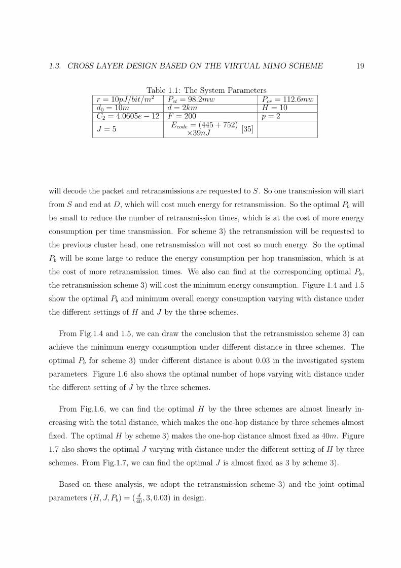
tance of each hop is assumed to be the same. The investigated system parameters are shown
in Tab.1.1. The employed linear block code is BCH(63, 39, 4).
From Fig.1.3, we can see that there exists an optimal Pb for three schemes with minimum
overall energy consumption. The optimal Pb for the retransmission scheme 1) is the least one,
and the optimal Pb for the retransmission scheme 3) is the largest one. For scheme 1) only D
1.3. CROSS LAYER DESIGN BASED ON THE VIRTUAL MIMO SCHEME 19
Table 1.1: The System Parametersr = 10pJ/bit/m2 Pct = 98.2mw Pcr = 112.6mwd0 = 10m d = 2km H = 10C2 = 4.0605e− 12 F = 200 p = 2
J = 5Ecode = (445 + 752)
×39nJ [35]
will decode the packet and retransmissions are requested to S. So one transmission will start
from S and end at D, which will cost much energy for retransmission. So the optimal Pb will
be small to reduce the number of retransmission times, which is at the cost of more energy
consumption per time transmission. For scheme 3) the retransmission will be requested to
the previous cluster head, one retransmission will not cost so much energy. So the optimal
Pb will be some large to reduce the energy consumption per hop transmission, which is at
the cost of more retransmission times. We also can find at the corresponding optimal Pb,
the retransmission scheme 3) will cost the minimum energy consumption. Figure 1.4 and 1.5
show the optimal Pb and minimum overall energy consumption varying with distance under
the different settings of H and J by the three schemes.
From Fig.1.4 and 1.5, we can draw the conclusion that the retransmission scheme 3) can
achieve the minimum energy consumption under different distance in three schemes. The
optimal Pb for scheme 3) under different distance is about 0.03 in the investigated system
parameters. Figure 1.6 also shows the optimal number of hops varying with distance under
the different setting of J by the three schemes.
From Fig.1.6, we can find the optimal H by the three schemes are almost linearly in-
creasing with the total distance, which makes the one-hop distance by three schemes almost
fixed. The optimal H by scheme 3) makes the one-hop distance almost fixed as 40m. Figure
1.7 also shows the optimal J varying with distance under the different setting of H by three
schemes. From Fig.1.7, we can find the optimal J is almost fixed as 3 by scheme 3).
Based on these analysis, we adopt the retransmission scheme 3) and the joint optimal
parameters (H, J, Pb) = ( d40
, 3, 0.03) in design.

20CHAPTER 1. CROSS LAYER DESIGN FOR WIRELESS SENSOR NETWORKS WITH VIRTUAL MIMO
1.3.3 End-to-end Transmission Scheme Design
Based on the design of the single-hop transmission, the end-to-end transmission scheme will
be designed. In the end-to-end transmission scheme, radio irregularity of wireless commu-
nications, multi-hop routing, retransmissions and end-to-end QoS provisioning are jointly
considered with the virtual MIMO scheme. In order to simplify the procedure of forming
cooperative nodes set in the virtual MIMO scheme, the clustering protocol, LEACH proto-
col, is used to organize the sensor nodes into multiple clusters. Then, the LEACH protocol
is extended to enable cluster heads form a multi-hop backbone, and the single-hop design in
the previous section is incorporated into each hop transmission. As assumed in the LEACH
protocol, each node has a unique node’s ID. The transmit power of each node can be ad-
justed, and the nodes are all time synchronized. Similarly, the operations of the proposed
scheme are broken into rounds. Each round consists of three phases: cluster formation phase,
during which the clusters are organized and the cooperative MIMO nodes are selected; rout-
ing phase, during which routing table is constructed; transmission phase, during which data
are transferred from the nodes to the cluster head and forwarded to the sink according to
the routing table.
Cluster Formation Phase
In this phase, each node will elect itself to be a cluster head with a probability p as specified
in the original LEACH protocol. After the cluster heads are elected, each cluster head will
broadcast an advertisement message (ADV) by transmit power Pout using a non-persistent
CSMA MAC protocol. The message contains the head’s ID. If a cluster head receives the
advertisement message from another head t and the received signal strength (RSS) exceeds
a threshold th, it will take cluster head t as a neighboring cluster head and record t’s ID. As
for the non cluster head, node j, it will record all the RSSs of the advertisement messages,
and choose the cluster head whose RSS is the maximum. Then, it will calculate and save
H(dj), G(djt, kjt), βjt and Poutjt by Eqns. (1.3), (1.5), (1.7) and (1.9). Then node j will
join the cluster by sending a join-request message (Join-REQ) to the chosen cluster head.
This message contains the information of the node’s ID, the chosen cluster head’s ID and

1.3. CROSS LAYER DESIGN BASED ON THE VIRTUAL MIMO SCHEME 21
the corresponding values of βjt. After a cluster head has received all join-request messages,
it will set up a TDMA schedule and transmit this schedule to its members as in the original
LEACH protocol. If the sink receives the advertisement message, it will find the cluster head
with the maximum RSS, and send the sink-position (Sink-POS) message to the cluster head
and mark the cluster head as the target cluster head (TCH).
After the clusters are formed, each cluster head will select corresponding optimal J co-
operative nodes for cooperative MIMO communications with each of its neighboring cluster
heads. As stated in Section II.A, J nodes with maximum βjt will be chosen to communicate
with a neighboring cluster head t. If no such J nodes can be found for t, t will be removed
from the neighbor list, since too much energy is consumed for communicating with t. After
selecting the cooperative nodes, the total energy per bit transmission for communications
with t, Ebt, can be derived by Eqn. (1.4). Then, Ebt, the ID set of the cooperative nodes
for each neighboring cluster head will be stored. At the end of this phase, the cluster head
will broadcast a cooperate-request message (COOPERATE-REQ) to each cooperative node,
which contains the ID of the cluster itself, the ID of the neighboring cluster head t, the IDs
of the cooperative nodes, and the index of the cooperative nodes in the cooperative nodes set
for each cluster head t. Each cooperative node that receives the cooperate-request message
(COOPERATE-REQ) will store the ID of t, the index and the transmit power Poutjt and
send back a cooperate-ACK message (COOPERATE-ACK) to the cluster head.
We assume the nodes are locally time synchronized in each cluster at the end of this phase.
This could be achieved by having each cluster head transmit a reference carrier and all its
cluster members lock to this reference carrier using a phase locked loop. In fact, the clock
jitter at the transmit nodes in transmission will cause inter-symbol interference (ISI). An
accurate synchronization algorithm should be implemented to have very fine synchronization
within each cluster, which will cost significant energy consumption. However, as stated
in [14], the clock jitter as large as 10% of the bit time do not have much effect on the
BER performance for the cooperative MISO scheme. So we do not implement the accurate
synchronization algorithm to save energy.
22CHAPTER 1. CROSS LAYER DESIGN FOR WIRELESS SENSOR NETWORKS WITH VIRTUAL MIMO
Routing Table Construction
To construct the routing table, the basic ideas of distance-vector based routing will be used.
Each cluster head will maintain a routing table, in which each entry contains Destination
Cluster ID, Next Hop Cluster ID, IDs of Cooperative Nodes, Mean Energy Consumption Per
Bit. Initially, only the neighbor cluster heads will have a record in the routing table. Then
each cluster head will simply inform its neighbor cluster heads of its routing table. After
receiving route advertisements from neighbor cluster heads, the cluster head will update its
routing table according to route cost and advertise to its neighbor cluster heads the modified
routes. After several rounds of route exchange and update, the routing table of each cluster
head will converge to the optimal one. Then, TCH will flood a target announcement message
(TARGET-ANNOUNCEMENT) containing its ID to each cluster head to enable the creation
of the paths to it.
Data Transmission
In this phase, cluster members will transmit first their data to the cluster head by multiple
frames. In each frame, each cluster member will transmit its data during its allocated
transmission slot specified by the TDMA schedule in Cluster Formation Phase, and then sleep
in other slots to save energy. The duration of a frame and the number of frames transmitted
to the cluster head in a slot are the same for all clusters. Thus the duration of each slot
depends on the number of nodes in the cluster. After a cluster head receives data frames
from its cluster members, it will perform data aggregation to remove the redundancy in the
data. After aggregating received data frames, the cluster head will forward the data packets
to the TCH by multiple-hops routing. In each single-hop communication, if there exist J
cooperative MIMO nodes, the cluster head will add a packet header to the data packet, which
includes the information of source cluster ID, next-hop cluster ID and destination cluster ID.
The cluster head will buffer and encode the data packet according to the linear block coding.
Then the encoded data packet is broadcasted. Once the corresponding cooperative nodes
receive the data packet, they will encode the data packet by orthogonal STBC, and transmit
the data to the cluster head in the next hop as an individual antenna with transmission power

1.4. THEORETICAL ANALYSIS OF THE CROSS LAYER DESIGN 23
Poutjt in the MIMO antenna array. In the cooperative MIMO scheme, the transmission delay
and channel estimation scheme proposed in [5] can be used in decoding. After receiving the
packet, the cluster head in the next hop will decode it and correct the bit errors by the linear
block coding. If a word error occurs after decoding, it will send a NACK message to the
previous cluster head to retransmit the packet, otherwise it will send an ACK message to
the previous cluster head to remove the buffered packet. The stop-and-wait ARQ scheme is
used for the retransmission requirements. The reason not to use other ARQ schemes, such
as selective repeat ARQ scheme, is that the transmission distance is so near in WSN that the
propagation latency can be ignored. So the throughput by the stop-and-wait ARQ scheme
is almost the same as other ARQ schemes. Due to its simplicity, it is more suitable to use
in WSN.
In order to improve the energy efficiency of the protocol, the communication parameters,
including kc, J and Pb, should be chosen as the joint optimal one. The choice of kc should
make the inter-cluster distance approximately 40m in the system parameters settings in
Tab.1.1.
1.4 Theoretical Analysis of The Cross Layer Design
In this section, we will analyze the energy consumption and end-to-end QoS performance of
the scheme. Then, an optimization model is developed to find the optimal parameters based
on these analyses.
1.4.1 Energy Consumption and End-to-end QoS Performance Analysis
As the scheme design in Section 1.3, during transmission each cluster head will find the
minimum energy consumption of relaying data packet among other cluster heads to the
sink. The multi-hop data transmission topology among cluster heads can be treated as a
short path tree (SPT), which is shown in Fig.1.8. The BER performance, Pb, on each link
will determine the packet throughput, which can be treated as the packet service rate µ for
24CHAPTER 1. CROSS LAYER DESIGN FOR WIRELESS SENSOR NETWORKS WITH VIRTUAL MIMO
the sender of the link. Therefore, the queuing latency and throughput of the node can be
modelled by the BER performance, Pb, according to the queuing theory. Based on the result,
the end-to-end latency and throughput can also be modelled in terms of the Pbs of all links.
According to the assumptions in Section.1.3, the mean time to transmit a packet can be
described as tf = nFB(F−pJ)
. Since the stop-and-wait ARQ scheme is used for the retransmis-
sion requirements, the throughput can be described as Eqn.(1.23) if the propagation latency,
the processing latency and the ACK packet transmission latency are ignored [37].
G =1− Pw(Pb)
tf(1.23)
From the view point of the network layer, the throughput of the stop-and-wait ARQ
scheme can be viewed as the packet service rate, which can be described as µ = 1−Pw(Pb)tf
packets/s. Suppose the packets arrive according to the Possion process and the packet
arrival rate is denoted as λ. Let P0(µ, λ), PN(µ, λ) and W (µ, λ) denote the probabilities of
the queue being empty, being full and the mean sojourn time for a packet including queuing
and servicing, respectively. The existing solutions by the queuing theory can be used directly
to compute P0, PN and W [38].
Now we are ready to model the end-to-end QoS performance in terms of the BER per-
formance of each link in SPT. The SPT can be represented by T =< V, ET >, where node
set V is the set of all cluster heads in the SPT, and edge set ET denotes the set of directed
communication links between each pair of cluster heads in the SPT. V can be grouped into
two subsets, the set of leaf cluster heads (denoted as Vs) and the set of internal cluster heads
(denoted as Vr). As for the leaf cluster head, such as S1 in Fig.1.8, it only receives the
packets from its cluster members. However, the internal cluster head, such as R1 in Fig.1.8,
not only receives the packets from its members but also the packets from its children cluster
heads in SPT. Then, the packet arrival rate can be described by
λi =
λc, (i ∈ Vs)∑j∈Nsi
µj(Pbj)(1− P0(µj(Pbj), λj)) + λc, (i ∈ Vr)(1.24)
1.4. THEORETICAL ANALYSIS OF THE CROSS LAYER DESIGN 25
where Nsi is the set of children cluster heads in SPT, λc is the intra-cluster packet arrival
rate and µj(Pbjk) =1−Pw(Pbj)
tf. To simplify the analysis, we assume λc are the same for all
clusters, which can be estimated by the number of nodes and the desired number of clusters.
However, the extension to the scenario with different λc is simple.
Therefore, the probabilities of the queue being empty, being full and the mean so-
journ time of a packet transmission for cluster head j can be described as P0(µj(Pbj), λj),
PN(µj(Pbj), λj) and W (µj(Pbj), λj).
Denote Lj as the path from cluster head j to the sink in SPT, the end-to-end latency and
throughput for j can be described by
Laj =∑
i∈LjW (µi(Pbi), λi)
Thj =∏
i∈Lj(1− PN(µi(Pbi), λi))
(1.25)
The mean end-to-end latency and throughput for the whole network can be described by
La({Pbj}) =∑
j∈Vs∪Vr λjLaj∑j∈Vs∪Vr λj
Th({Pbj}) =∑
j∈Vs∪Vr λjThk∑j∈Vs∪Vr λj
(1.26)
Strictly speaking, we only considered the QoS performance of the inter-cluster communi-
cation in Eqn.(1.26). We have considered the QoS performance of the intra-cluster commu-
nication in [26], which will not be discussed here due to the limited space.
On the other hand, the overall energy consumption of all cluster heads can be described
by
Ea({Pbj}) =∑
j∈Vs∪Vr
1
1− Pw(Pbj)[Ecode + E0(d0, J) + E1(Pbj, dj, J)] (1.27)
1.4.2 Parameters Optimization
Based on the above analysis, we developed a model to find the optimal {Pbj} to minimize
the overall energy consumption under the application’s end-to-end QoS requirements, which
26CHAPTER 1. CROSS LAYER DESIGN FOR WIRELESS SENSOR NETWORKS WITH VIRTUAL MIMO
Table 1.2: The Optimization ModelObjective: minEa({Pbj}). Refer to Eqn.(1.27) for the expression of Ea(Pbj).Subject to:
• The requirement on mean end-to-end latency, La({Pbj}) ≤ τapp.
• The requirement on mean end-to-end packet loss ratio, Th({Pbj}) ≤ thapp.
• Pbmin ≤ Pbj ≤ Pbmax.
Expected solution: Find the optimal {Pbj}.
are shown in Tab.1.2.
By solving the optimization model, we can obtain the optimal {Pbj} to provide the end-
to-end QoS requirements by minimum overall energy cost. However, the problem shown in
Tab.1.2 is a nonlinear constrained optimization problems, which is difficult to solve especially
when the number of Pbj is large. Due to its efficiency in solving such optimization problems,
we use the Particle Swarm Optimization (PSO) algorithm to find the optimal solution. PSO
algorithm is proposed by James Kennedy and R. C. Eberhart in 1995 [36], motivated by social
behavior of organisms such as bird flocking and fish schooling. In the PSO algorithm, the
local search method and global search method are combined to find the optimal solution. In
using the PSO algorithm to solve our problem, we define the particle as the vector containing
the {Pbj}. A population with Np particles is generated. The PSO algorithm is iterated for
Niter times to find the optimal solution. Also since our problem is a constrained optimization
problem, we convert it to a unconstrained one by the punished function.
During transmission, the sink node will determine the optimal Pbj for each link in the
SPT and transmit Pbj to the related cluster head via the control packet. After receiving the
control packet, within its cluster, the cluster head will broadcast a transmit power adjustment
packet including Pbj and the ID of its parent cluster head in the SPT. After receiving the
adjustment packet, the cooperative nodes corresponding to the ID of the parent cluster head
will adjust the transmit power by the Pbj according to Eqn.(1.7). This procedure requires the
knowledge on the topology information of the SPT and the channel gains of each link. We
assume that each cluster head will report the following information to the sink, such as the
ID of its parent cluster head and the channel gains between itself and its parent cluster head
in the SPT during the Routing Table Construction phase. To implement the optimization

1.5. SIMULATION AND NUMERICAL RESULTS 27
procedure in a more distributive manner is one of our research interests in the future work.
1.5 Simulation and Numerical Results
In this section, we evaluate the energy saving performance and QoS provisioning of the
proposed cross layer design based on virtual MIMO. Our experiments are organized as fol-
lows: Firstly, we demonstrate the energy saving performance of the proposed scheme in the
phenomena of fading and radio irregularity; Secondly, we investigate the QoS provisioning
performance of the design based on the optimization of {Pbj} of each link by the optimization
model proposed in Section.1.4. In the simulations, the related system parameters are the
same as shown in Tab.1.1.
1.5.1 Energy Saving Performance of The Cross Layer Design
In order to evaluate the energy saving performance of the proposed cross layer design, we
simulate the operation of the cross layer design in multiple rounds, record its’ energy con-
sumption and compare to other schemes. The procedure of this simulation will be discussed
in this section.
In the simulations, 400 nodes are randomly deployed on a 200× 200 field. The location
of the sink is randomly chosen in each round. Each node begins with 400J of energy and an
unlimited amount of data packets to send to the sink. When the nodes use up their limited
energy during network operation, they can not transmit or receive data any longer.
During the simulation, we tracked the accumulated number of packets transferred to the
sink, the amount of energy and duration required to deliver the data to the sink, and the
percentage of nodes alive. We are interested in the transmission quality and energy saving
performance of the proposed scheme. The performance of the proposed Multi-Hop MIMO-
LEACH scheme is compared with the original LEACH and the multi-hop LEACH scheme,
in which cooperative MIMO communications is not implemented. The optimal value of kc

28CHAPTER 1. CROSS LAYER DESIGN FOR WIRELESS SENSOR NETWORKS WITH VIRTUAL MIMO
for the original LEACH is determined by the model in [15]. We also develop a similar model
to find the optimal kc for the multi-hop LEACH scheme, which will not be discussed here
due to the limited space. In the investigated scenario, the optimal kc for the original LEACH
protocol, the multi-hop LEACH scheme and the proposed scheme, are found and set to 3,
41 and 27, respectively. The optimal J for the proposed scheme is found to be 3.
Due to the aggregation operation, the number of effective received packets by sink [15]
is deemed as the number of “real”packets after aggregation. Specifically, if no aggregation
carries out, the number of effective received packets equals to the number of successfully
received packets. If the aggregation operation in transmission is information lossless, the
number of effective received packets is just the number of total packets transferred by the
source nodes. We believe that the number of effective received packets is a good application-
independent indication of the transmission quality.
Fig. 1.9 and 1.10 show the total number of effective packets received at the sink over time
and the total number of effective packets received at the sink per a given amount of energy.
Fig. 1.9 shows that during its lifetime the LEACH protocol can obtain better latency
performance compared to the multi-hop LEACH scheme and the proposed MIMO LEACH
scheme. The reason is that the multi-hop operation in the multi-hop LEACH scheme and the
Multi-hop MIMO-LEACH scheme will increase the latency, and thus result in a less number
of data packets sent to the sink for a given period of time. However, the better latency
performance of the LEACH protocol comes from the more energy consumption compared
to the other two schemes. Especially, in the fading channel environment, LEACH protocol
will consume much more energy due to its single-hop transmission from the cluster heads
to the sink, which will result in less network lifetime and less total number of transmitted
packets. Fig. 1.10 shows that, with the same amount of energy consumption, the Multi-
hop MIMO-LEACH scheme can transmit much more data packets compared to the LEACH
protocol and the multi-hop LEACH scheme. From these simulation results, we can find that
the Multi-hop MIMO-LEACH scheme is more suitable for the application scenarios which
have high requirements on network lifetime but low requirements on latency.
Fig. 1.11 shows the percentage of nodes alive over time. From Fig. 1.11, we can find that

1.5. SIMULATION AND NUMERICAL RESULTS 29
the proposed Multi-hop MIMO-LEACH scheme can improve the network lifetime greatly. If
we define the network lifetime of WSN as the duration of more than 70% of network nodes
are alive, it can be observed that the network lifetime of WSN with the original LEACH
protocol, the multi-hop LEACH scheme and the proposed Multi-hop MIMO-LEACH scheme
are about 0.7 × 10⁴, 8.2 × 10⁴ and 11 × 104s, respectively. The improvement on network
lifetime obtained by the Multi-Hop MIMO-LEACH scheme is significant.
However, the percentage of nodes alive over time is not always a good indication to the
energy saving performance of a protocol. For example, during the same time, though one
protocol is worse than other protocols in terms of the energy saving performance, it will still
consume less energy if it transmits less packets than other protocols. Thus, its lifetime is
likely longer. In order to further investigate the energy saving performance, we also simulate
the performance in terms of the percentage of nodes alive per amount of effective data
packets received at the sink, which is shown in Fig. 1.12. From Fig. 1.12, we find that the
proposed Multi-hop MIMO-LEACH scheme needs significantly less energy to transmit the
same amount of data packets. Therefore, the improvement on network lifetime obtained by
the Multi-hop MIMO-LEACH scheme is significant.
On the other hand, the impacts of the parameters, including the number of cluster heads,
kc and the number of cooperative nodes, J , are also investigated in the simulation. Fig. 1.13
and 1.14 show the percentage of nodes alive over time in different settings of kc and J .
From the simulation results including those shown in Fig. 1.13 and 1.14, we can find that
the energy saving performance of the proposed scheme is impacted by the setting of these
parameters. As for the number of cluster heads (HeadNum), a large value of HeadNum will
reduce the distance for each single hop transmission, which will reduce the transmit energy
consumption; A large HeadNum also generates a wide search space for the routing table con-
struction, which will also reduce the transmit energy consumption further. However, larger
is HeadNum, more number of hops in transmission to the sink is needed, which causes more
circuit energy consumption for relaying the data packets. Therefore, the number of cluster
heads should be chosen to trade off the transmit energy consumption and circuit energy con-
sumption. As for the number of cooperative nodes, a certain number of cooperative nodes
30CHAPTER 1. CROSS LAYER DESIGN FOR WIRELESS SENSOR NETWORKS WITH VIRTUAL MIMO
can form the effective independent multi-path transmission so as to energy-efficiently combat
the fading effects. However, too many cooperative nodes will result in large circuit energy
consumption, which will cause large overall energy consumption. Therefore, the number of
cooperative nodes should also be chosen to trade off the transmit energy consumption and
the circuit energy consumption.
1.5.2 QoS Provisioning Performance of The Cross Layer Design
In Section.1.4, we have proposed an end-to-end QoS model in terms of the BER performance
of each link in the SPT. We also propose to use the PSO algorithm to find the optimal BER
performance of each link to minimize the overall energy consumption without violating the
end-to-end QoS requirements. In this section, the numerical results will be presented. The
structure of the SPT in experiments is shown in Fig.1.15, where S1, S2, S3 and S4 are the
source cluster heads; R1 and R2 are the internal cluster heads; the number shown on each link
is the distance of the link; Pbi is the BER performance of link i, and the intra-cluster packet
arrival rates λc for all cluster heads are 40 pps. Np is set to be 10000 and Niter is set to be
100 in the simulation. In the experiments, we search the optimal BER performance of each
link by PSO algorithm to minimize the overall energy consumption with varied end-to-end
QoS requirements.
Figure 1.16 to 1.19 show the convergence of the minimum overall energy consumption, end-
to-end latency, end-to-end throughput and Pbs during the search process of PSO algorithm.
The desired end-to-end latency and end-to-end throughput are 0.04s and 0.80 respectively.
From Fig. 1.16 to 1.19, we can find the algorithm can converge in about 30 iterations, so the
convergence speed is fast. Therefore, the PSO algorithm is efficient to solve our problem.
The optimal Pb5, Pb6 are less than Pb1 to Pb4, the reason is that the internal links should have
smaller optimal BER to make the throughput larger than the throughput of the children
links in SPT for end-to-end QoS provisioning.
We also did the experiment to search the minimum energy consumption and optimal Pbs
with time-varying end-to-end QoS requirements. In the experiment, the desired end-to-end
1.5. SIMULATION AND NUMERICAL RESULTS 31
latency is varied from 0.008s to 0.038s, and the desired end-to-end throughput is fixed as
0.8, then the optimal Pbs and the minimum overall energy consumption are found by the
PSO algorithm. The energy saving performance by employing the optimal Pbs is defined as
ηE =Eref−Eopt
Eref×100%, where Eref and Eopt are the overall energy consumptions by a random
setting and optimal setting of Pbs. Figure 1.20 and 1.21 show the actual end-to-end latency
and end-to-end throughput acquired by the algorithm. Figure 1.22 shows the energy saving
performance varied with the desired end-to-end latency. Figure 1.23 shows the optimal Pbs
varied with the desired end-to-end latency.
Furthermore, in order to investigate the energy saving performance and end-to-end QoS
provisioning of the protocol in a large-scale network. We also did the simulation to search
the optimal Pbs by PSO algorithm in the scenario of large-scale network, in which 400 sensor
nodes are randomly deployed over a 200m × 200m area and the nodes are clustered into
22 clusters. The intra-cluster packet arrival rates λc for all cluster heads are 60pps. The
topology of the network is shown in Fig.1.24.
Figure 1.25 to 1.27 show the convergence of the minimum overall energy consumption,
end-to-end latency and end-to-end throughput during the search process of PSO algorithm.
For the network shown in Fig.1.24, we also did the experiments to search the minimum
energy consumption with time-varying end-to-end QoS requirements. In the experiment,
the desired end-to-end latency is varied from 11.8ms to 14.8ms, and the desired end-to-end
throughput is fixed as 0.78. Figure 1.28 and 1.29 show the actual end-to-end latency and
energy saving performance varied with the desired end-to-end latency.
From the experimental results, it can be seen that by adjusting the Pb of each link, the
actual end-to-end QoS performances are varied with the end-to-end QoS requirements. And
the significant energy saving performance can be acquired by adjusting the optimal BER
performance.
32CHAPTER 1. CROSS LAYER DESIGN FOR WIRELESS SENSOR NETWORKS WITH VIRTUAL MIMO
1.6 Conclusion and Open Issues
In this chapter, we propose a cross layer design based on virtual MIMO scheme to increase
the energy efficiency and provide the end-to-end QoS guarantee. In the scheme, radio irreg-
ularity of wireless communications, multi-hop routing, retransmissions and end-to-end QoS
provisioning are jointly considered with the virtual MIMO scheme. In the cross layer de-
sign, the concept of clustering is adopted to organize the sensor nodes into multiple clusters
and form the cluster heads as a multi-hop backbone. Then, the virtual MIMO scheme is
incorporated into each single-hop transmission between each pair of cluster heads. In each
single-hop transmission, three HARQ-based retransmission schemes are considered to incor-
porate into the virtual MIMO scheme. The average energy consumption for a successful
packet transmission by the virtual MIMO scheme under the three retransmission schemes
are analyzed and compared. Then the retransmission scheme by hop-by-hop recovery is
incorporated into the virtual MIMO scheme due to its efficiency. Then, an adaptive coop-
erative nodes selection strategy is also designed in the protocol. Based on the single-hop
transmission scheme, the end-to-end transmission scheme is designed which jointly integrate
virtual MIMO scheme, multi-hop routing scheme and retransmission scheme to improve the
performance of energy efficiency, reliability and QoS guarantees. Based on the cross layer
design, we also developed the model for end-to-end QoS and overall energy consumption of
the design in terms of the BER performance in each link of the SPT. A nonlinear constrained
programming model is also designed to find the optimal BER performances for all the links
in the SPT. The PSO algorithm is employed to solve the programming problem. Simulation
results show the effectiveness of the proposed protocol to achieve the goals of minimizing
energy consumption. The numerical results show that by adjusting the BER performance of
each link, the actual end-to-end QoS performance can be varied with the requirements and
the energy can be saved significantly.
In the future work, we are interested in incorporating the network layer retransmission
schemes into the multi-hop virtual MIMO protocol. In addition, a distributed protocol
will be developed to adjust the BER performance of each link in the SPT to provide the
end-to-end QoS guarantee while minimize the overall energy consumption.
1.6. CONCLUSION AND OPEN ISSUES 33
References
[1] S. M. Alamouti, “Simple transmit diversity technique for wireless communications,”
IEEE Journal of Selected Areas in Communications, vol.16, pp.1451-1458, 1998.
[2] V. Tarokh, H. Jafarkhani and A. Calderbank, “Space-Time Block Codes from orthogonal
Design,” IEEE Trans. Inform. Theory, vol 45, no.5, pp. 1456-1466, July 1999.
[3] M. Dohler, A. Gkelias, H. Aghvami, “A Resource Allocation Strategy for Distributed
MIMO Multi-Hop Communication Systems,” IEEE Communications Letters, vol. 8,
pp.99-101, Feb 2004.
[4] L. Musavian, M. Dohler, R. Nakhai and H. Aghvami, “Closed Form Capacity Expres-
sions of Orthogonalised Correlated MIMO Channel,” IEEE Communications Letters,
vol. 8, pp. 365-367, June 2004.
[5] X. Li, “Energy efficient wireless sensor networks with transmission diversity,” IEE Elec-
tronics Letters, vol.39, pp.1753-1755, Nov. 2003.
[6] X. Li, “Space Time Coded Multiple Transmission Among Distributed Transmitters
Without Perfect Synchronization,” IEEE Signal Processing Letters, vol.11, pp.948-951,
Dec. 2004.
[7] X. Li, M. Chen and W.Liu “Application of STBC-Encoded Cooperative Transmissions
in Wireless Sensor Networks,” IEEE Signal Processing Letters, vol.12, pp.134-137, Feb.
2005.
[8] X. Li, “Blind channel estimation and equalization in wireless sensor networks based on
correlations among sensors,” IEEE Transactions on Signal Processing, vol.53, pp.1511-
1519, April. 2005.
[9] B. Azimi-Sadjadi and A. Mercado, “Diversity gain for cooperating nodes in multi-hop
wireless networks,” in IEEE VTC 2004 Fall, vol.2, pp.1483-1487, Sept. 2004.
[10] S. Cui, A. J. Goldsmith and A. Bahai, “Energy-efficiency of MIMO and Cooperative
MIMO Techniques in Sensor Networks,” IEEE Journal of Selected Areas in Communi-
cations, vol.22, pp.1089-1098, Aug. 2004.
[11] S. K. Jayaweera, “Energy Analysis of MIMO Techniques in Wireless Sensor Networks,”
in 38th Annual Conference on Information Sciences and Systems (CISS 04), Princeton,
NJ, Mar. 2004.
[12] S. K. Jayaweera, “An energy-efficient virtual MIMO architecture based on V-BLAST
34CHAPTER 1. CROSS LAYER DESIGN FOR WIRELESS SENSOR NETWORKS WITH VIRTUAL MIMO
processing for distributed wireless sensor networks,” in 2004 First Annual IEEE Com-
munications Society Conference on Sensor and Ad Hoc Communications and Networks,
pp.299 308, Oct. 2004.
[13] J. N. Laneman and G. W. Wornell, “Distributed space-time-coded protocols for ex-
ploiting cooperative diversity in wireless networks,” IEEE Transactions on Information
Theory, vol.49, pp.2415-2425, Oct. 2003.
[14] S. Jagannathan, H. Aghajan H, and A. Goldsmith, “The effect of time synchronization
errors on the performance of cooperative MISO systems,”, in IEEE Global Telecommu-
nications Conference Workshops pp.102 107, Dec. 2004.
[15] W. R. Heinzelman, A. Chandrakasan, and H. Balarislman, “An Application-Specific
Protocol Architecture for Wireless Microsensor Networks,” IEEE Transactions on Wire-
less Communications, vol.1, no.4, pp.660-670, Oct 2002.
[16] C. Y. Wan and A. T. Campbell, and L. Krishnamurthy, “Pump-Slowly, Fetch-Quickly
(PSFQ): A Reliable Transport Protocol for Sensor Networks,” IEEE Journal of Selected
Areas in Communications, vol.23, pp.862-872, April. 2005.
[17] F. Stann and J. Heidemann, “RMST: reliable data transport in sensor networks,” in
First IEEE Int. Workshop on Sensor Network Protocols and Applications, pp.102-113,
May 2003.
[18] Y. Sankarasubramaniam, O. B. Akan, and I. F. Akyildiz, “ESRT: Event-to- Sink Re-
liable Transport in Wireless Sensor Networks,” in ACM MobiHoc, pp.177-188, June
2003.
[19] B. Deb, S. Bhatnagar and B. Nath, “ReInForM: reliable information forwarding using
multiple paths in sensor networks,” in IEEE LCN’03, pp.406-415, Oct. 2003.
[20] N. Tezcan, E. Cayirci and M. U. Caglayan, “End-to-end reliable event transfer in wireless
sensor networks,”, in IEEE PIMRC’04, vol.2, pp.989-994, Sept. 2004.
[21] C. Taddia and G. Mazzini, “On the energy impact of four information delivery methods
in wireless sensor networks,” IEEE Communications Letters, vol.9, pp.118-120, Feb.
2005.
[22] K. Sohrabi, J. Gao, V. Ailawadhi and G. J. Pottie, “Protocols for self-organization of a
wireless sensor network,” IEEE Personal Communications, vol.7 pp.16-27, Oct. 2000.
[23] T. He, J. A. Stankovic, L. Chenyang and T. Abdelzaher, “SPEED: a stateless protocol
1.6. CONCLUSION AND OPEN ISSUES 35
for real-time communication in sensor networks,” in Proc. IEEE ICDCS’03, pp.46-55,
May 2003.
[24] K. Akkaya and M. Younis, “Energy-aware routing of time-constrained traffic in wireless
sensor networks,” Journal of Communication Systems, Special Issue on Service Differ-
entiation and QoS in Ad Hoc Networks, vol. 17, pp. 663-687, 2004.
[25] K. Akkaya and M. Younis, “Energy and QoS aware Routing in Wireless Sensor Net-
works,” Journal of Cluster Computing Journal, Special Issue on Ad Hoc Networks (to
appear).
[26] Y. Yuan, Z. K. Yang, Z. H. He, J. H. He, “An Integrated Energy Aware Wireless Trans-
mission System for QoS Provisioning in Wireless Sensor Network,“ Elsevier Journal of
Computer Communications, Special Issue on Dependable Wireless Sensor Networks (to
appear).
[27] S. Cui, A. J. Goldsmith, and A. Bahai, “Energy-constrained modulation optimizatoin
for coded systems,” Proc. IEEE GlobeCom’03, vol.1, pp.372 376, Dec 2003.
[28] C. S. Park, and K. B. Lee, “Transmit Power Allocation for BER Performance Improve-
ment in Multicarrier Systems,” IEEE Transactions on Communications, vol. 52, pp.
1658-1663, Oct 2004.
[29] A. R. K. Sastry, “Performance of hybrid error control schemes on satellite channels,”
IEEE Transactions on Communications, vol. 23, pp. 689 694, July 1975.
[30] A. R. K. Sastry, and L. N. Kanal, “Hybrid error control using retransmission and
generalized burst-trapping codes,” IEEE Transactions on Communications, vol. 24, pp.
385 393, April 1976.
[31] D. M. Mandelbaum, “An adaptive-feedback coding scheme using incremental redun-
dancy,” IEEE Transactions on Information Theory, vol. 20, pp. 388 389, May 1974.
[32] A. Banerjee, D. Costello, and T. Fuja, “Diversity combining techniques for bandwidth-
efficient turbo ARQ systems,” Proceedings of IEEE International Symp. on Inform. Th.,
June 2001.
[33] D. Chase, “Code-combining - a maximum likelihood decoding approach for combining
an arbitrary number of noisy packets,” IEEE Transactions. on Communications, vol.
33, May 1985.
[34] J. Hagenauer, “Rate-compatible punctured convolutional codes and their applications,”
36CHAPTER 1. CROSS LAYER DESIGN FOR WIRELESS SENSOR NETWORKS WITH VIRTUAL MIMO
IEEE Transactions on Communications, vol. 36, pp. 389 400, April 1985.
[35] R. Min, M. Bhardwaj, S. H. Cho, et al, “Low-power wireless sensor networks,” in 14th
International Conference on VLSI Design (VLSI DESIGN 2001) pp.205 210, Jan. 2001.
[36] J. Kennedy and R. C. Eberhart, “Particle Swarm Optimization,” in Proc. IEEE Int.
Conf. Neural Networks, pp.1942-1948, 1995.
[37] X. R. Xie, Computer Networks, 2nd Version (in Chinese), Publishing House of Elec-
tronics Industry, China, 1999.
[38] D. J. Lu, Random process and application (in Chinese), Tsinghua Press, China, 1986.
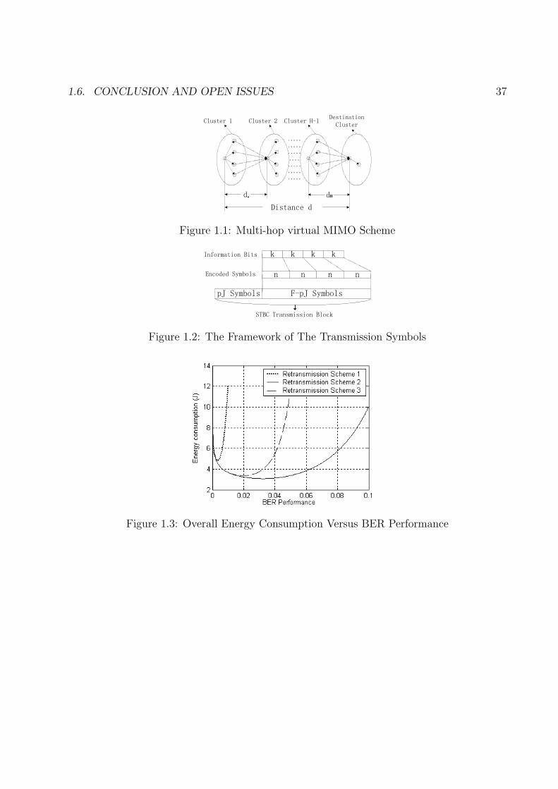
1.6. CONCLUSION AND OPEN ISSUES 37
��
� �
� � � � � � � �
�������� �������� ��������� � ���� � � �� � �
�������
Figure 1.1: Multi-hop virtual MIMO Scheme
� � � �
� � � �
� � � � � � � � �� � � � � � �
�������������
�� �� � � � � �� �� �
� � �� � ����������� �� �
Figure 1.2: The Framework of The Transmission Symbols
Figure 1.3: Overall Energy Consumption Versus BER Performance
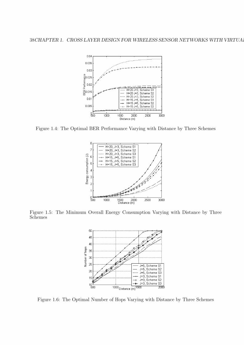
38CHAPTER 1. CROSS LAYER DESIGN FOR WIRELESS SENSOR NETWORKS WITH VIRTUAL MIMO
Figure 1.4: The Optimal BER Performance Varying with Distance by Three Schemes
Figure 1.5: The Minimum Overall Energy Consumption Varying with Distance by ThreeSchemes
Figure 1.6: The Optimal Number of Hops Varying with Distance by Three Schemes
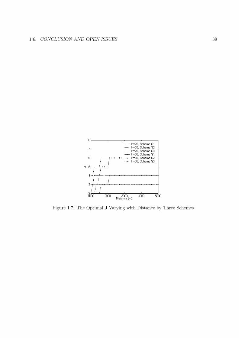
1.6. CONCLUSION AND OPEN ISSUES 39
Figure 1.7: The Optimal J Varying with Distance by Three Schemes
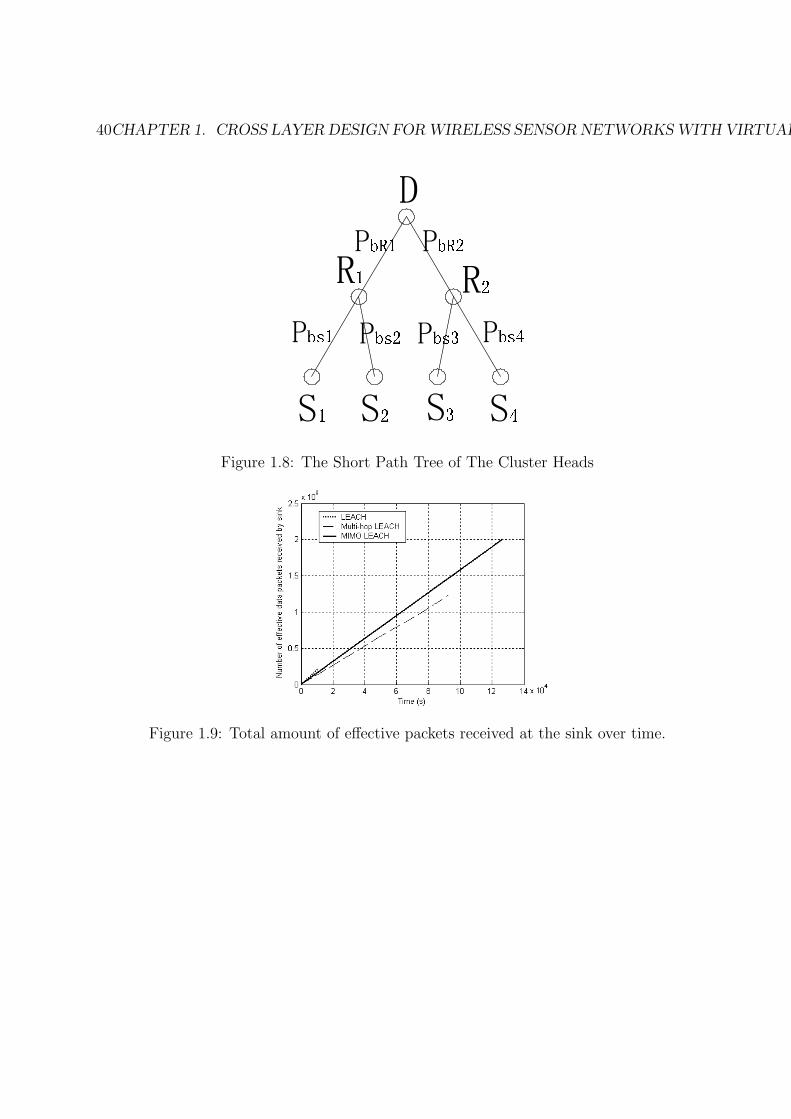
40CHAPTER 1. CROSS LAYER DESIGN FOR WIRELESS SENSOR NETWORKS WITH VIRTUAL MIMO
� � � � � � � �
� � � �
�
� ��� � � ����� � ���� � �����
� �� � � ����
Figure 1.8: The Short Path Tree of The Cluster Heads
Figure 1.9: Total amount of effective packets received at the sink over time.
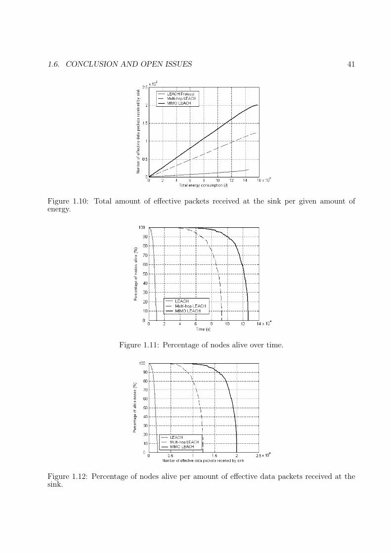
1.6. CONCLUSION AND OPEN ISSUES 41
Figure 1.10: Total amount of effective packets received at the sink per given amount ofenergy.
Figure 1.11: Percentage of nodes alive over time.
Figure 1.12: Percentage of nodes alive per amount of effective data packets received at thesink.
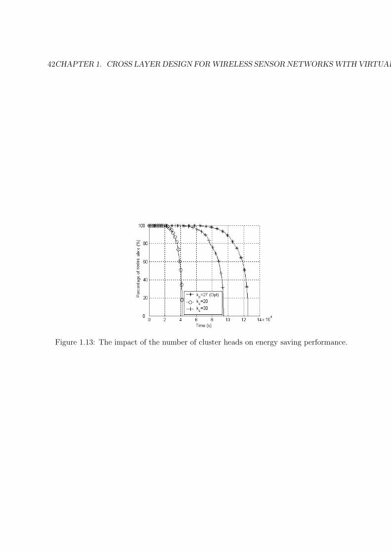
42CHAPTER 1. CROSS LAYER DESIGN FOR WIRELESS SENSOR NETWORKS WITH VIRTUAL MIMO
Figure 1.13: The impact of the number of cluster heads on energy saving performance.
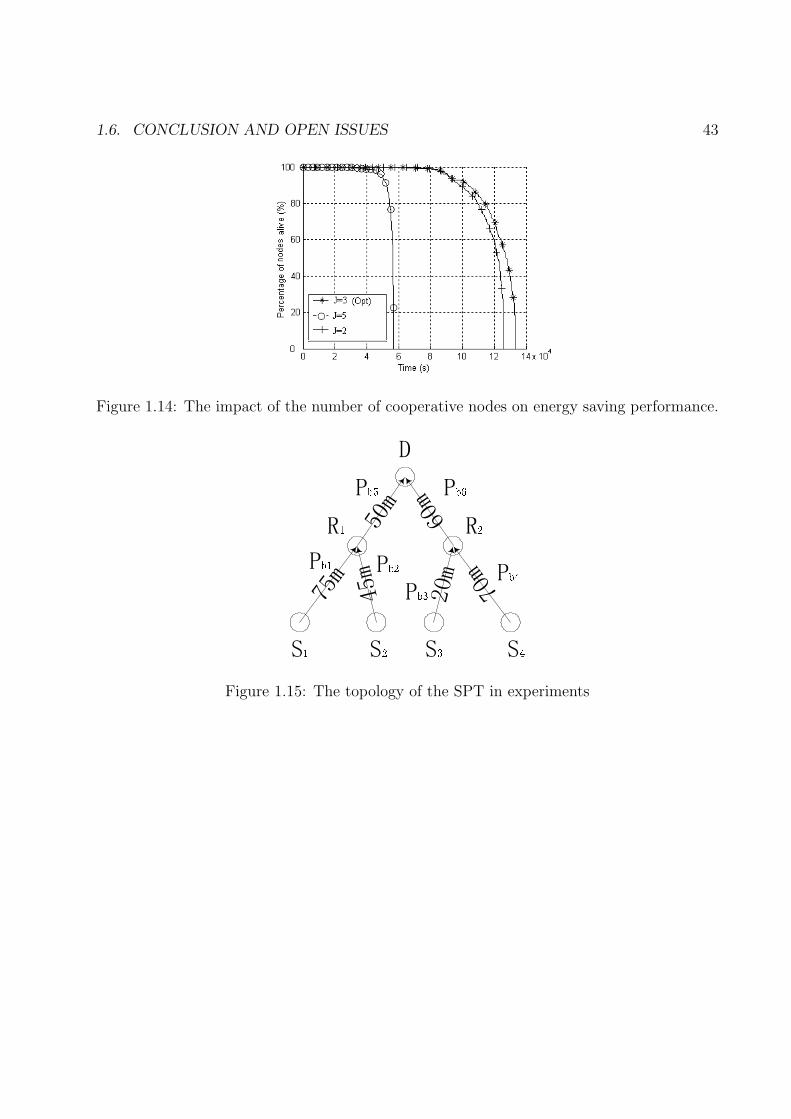
1.6. CONCLUSION AND OPEN ISSUES 43
Figure 1.14: The impact of the number of cooperative nodes on energy saving performance.
���
���
���
���
���
���
� � � � � � � �
� � � �
�
� � � � ���
� �������
� ��� � ���
Figure 1.15: The topology of the SPT in experiments
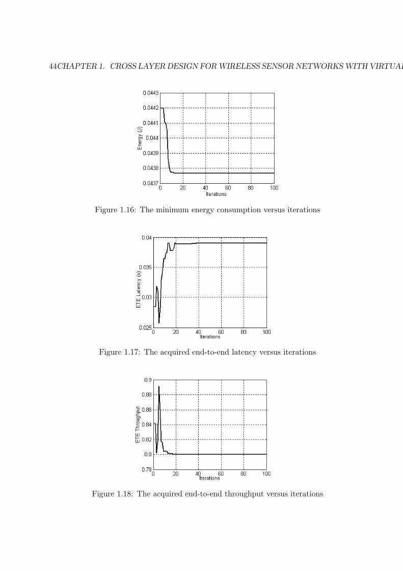
44CHAPTER 1. CROSS LAYER DESIGN FOR WIRELESS SENSOR NETWORKS WITH VIRTUAL MIMO
Figure 1.16: The minimum energy consumption versus iterations
Figure 1.17: The acquired end-to-end latency versus iterations
Figure 1.18: The acquired end-to-end throughput versus iterations
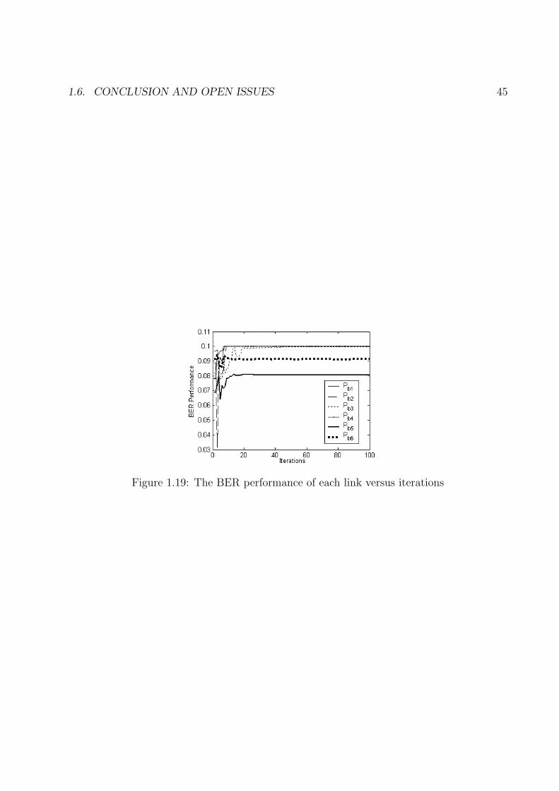
1.6. CONCLUSION AND OPEN ISSUES 45
Figure 1.19: The BER performance of each link versus iterations
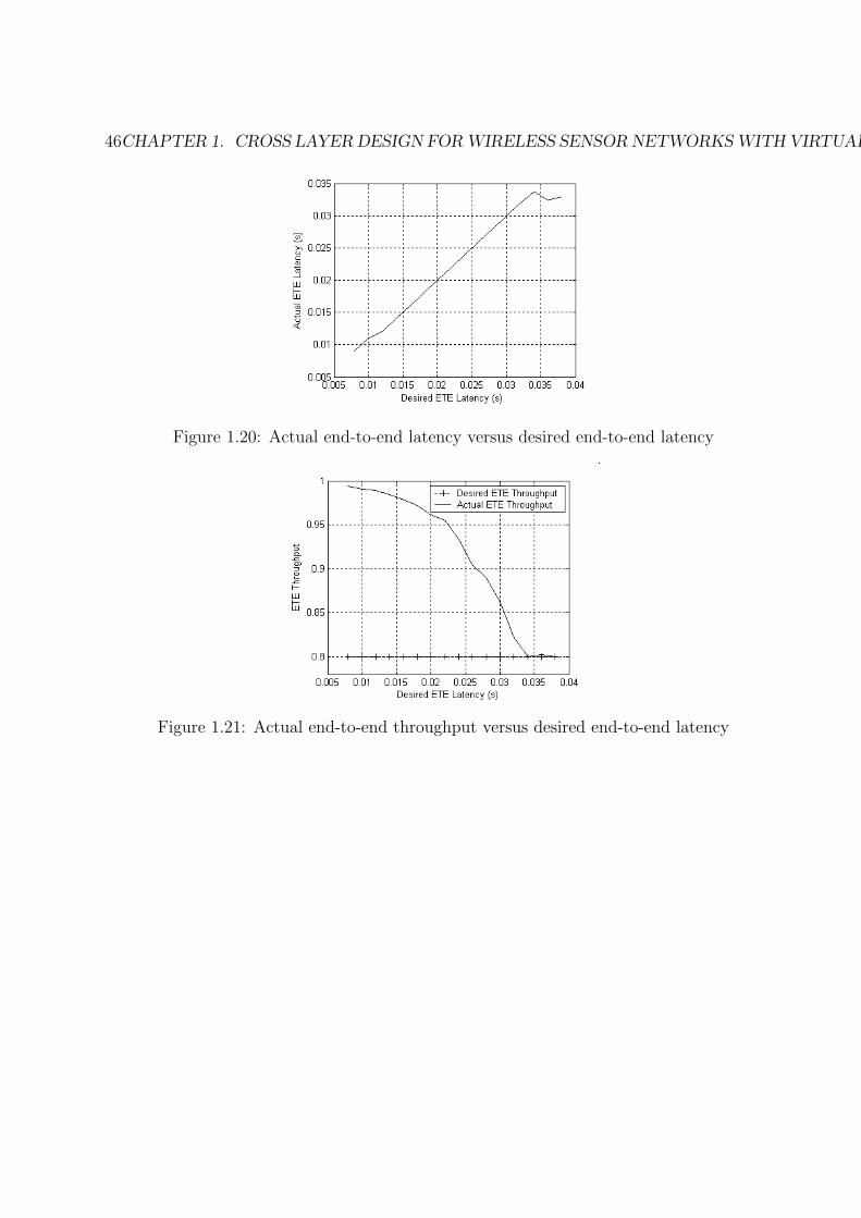
46CHAPTER 1. CROSS LAYER DESIGN FOR WIRELESS SENSOR NETWORKS WITH VIRTUAL MIMO
Figure 1.20: Actual end-to-end latency versus desired end-to-end latency
Figure 1.21: Actual end-to-end throughput versus desired end-to-end latency
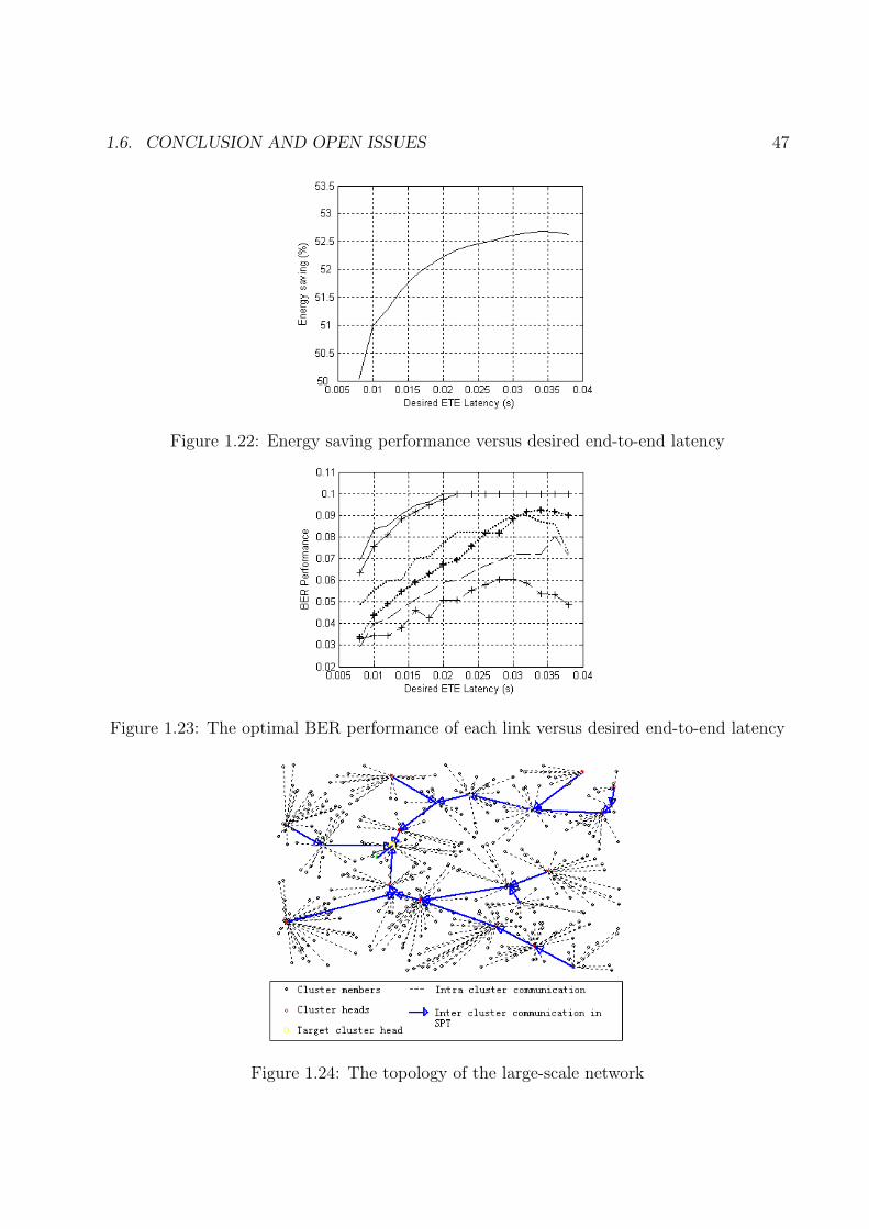
1.6. CONCLUSION AND OPEN ISSUES 47
Figure 1.22: Energy saving performance versus desired end-to-end latency
Figure 1.23: The optimal BER performance of each link versus desired end-to-end latency
Figure 1.24: The topology of the large-scale network
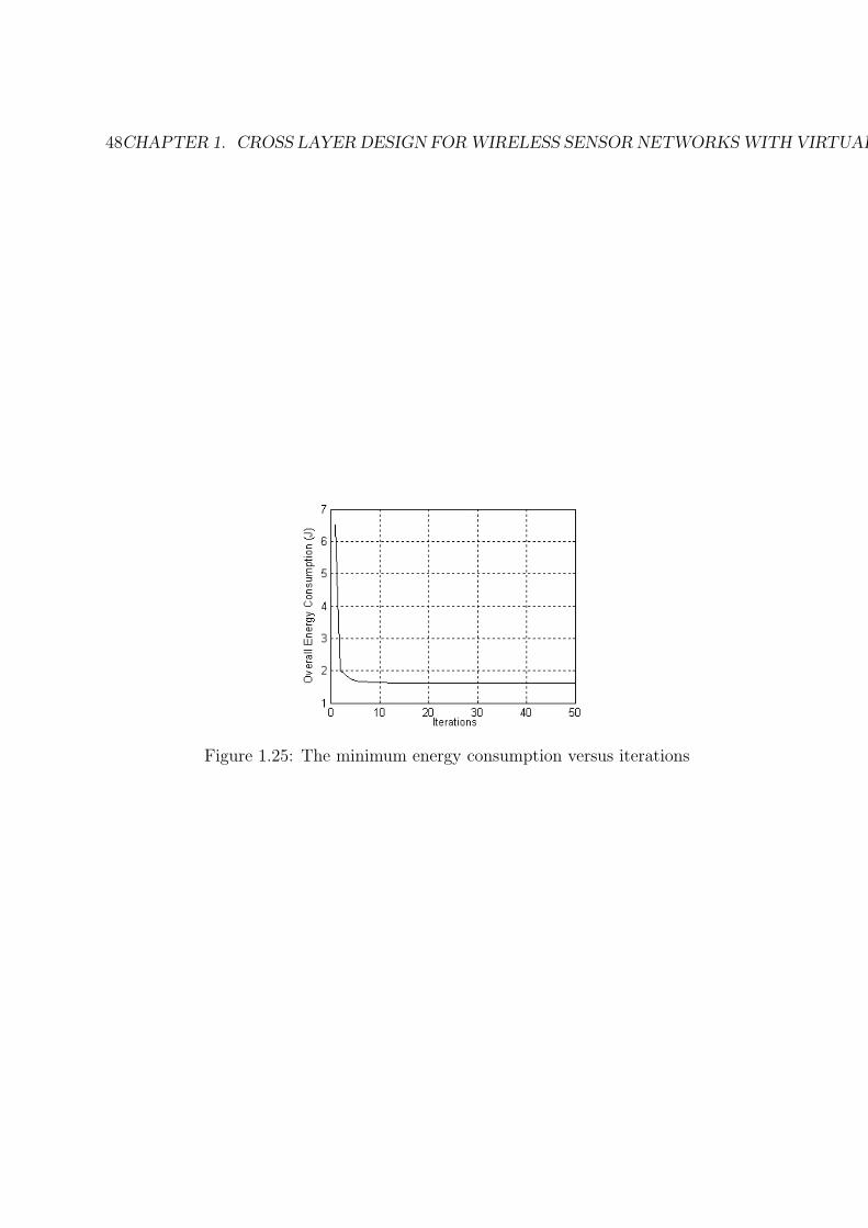
48CHAPTER 1. CROSS LAYER DESIGN FOR WIRELESS SENSOR NETWORKS WITH VIRTUAL MIMO
Figure 1.25: The minimum energy consumption versus iterations
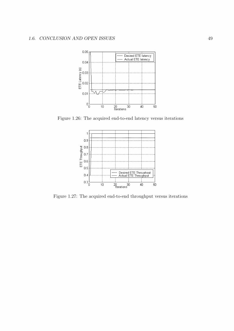
1.6. CONCLUSION AND OPEN ISSUES 49
Figure 1.26: The acquired end-to-end latency versus iterations
Figure 1.27: The acquired end-to-end throughput versus iterations
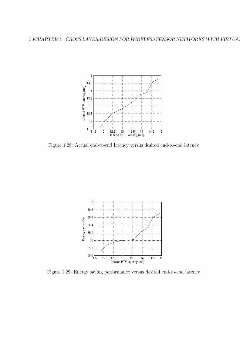
50CHAPTER 1. CROSS LAYER DESIGN FOR WIRELESS SENSOR NETWORKS WITH VIRTUAL MIMO
Figure 1.28: Actual end-to-end latency versus desired end-to-end latency
Figure 1.29: Energy saving performance versus desired end-to-end latency