Embed Size (px)
Citation preview
Distortion and Displacement
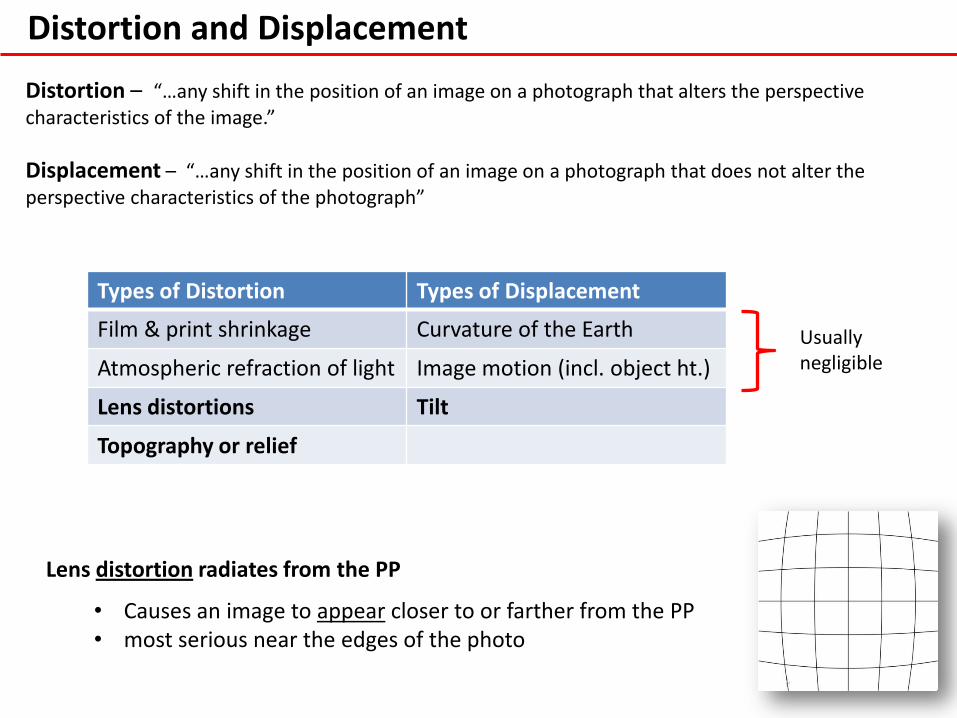
Distortion – “…any shift in the position of an image on a photograph that alters the perspective characteristics of the image.”
Displacement – “…any shift in the position of an image on a photograph that does not alter the perspective characteristics of the photograph”
Types of Distortion Types of Displacement
Film & print shrinkage Curvature of the Earth
Atmospheric refraction of light Image motion (incl. object ht.)
Lens distortions Tilt
Topography or relief
Usually negligible
Lens distortion radiates from the PP
• Causes an image to appear closer to or farther from the PP • most serious near the edges of the photo

Distortion and Displacement
I. Principal Points (PP) & Conjugate Principal Points (CPP) – Not the only points of interest on an aerial photo
A) Nadir & Isocenter – also important, especially on oblique photos.
B) PP – physical or optical center of an uncropped photo (intersection of diagonal fiducials)
1) If a photo is truly vertical, PP is directly beneath the aircraft
2) Not so on and obliques
3) Distortions due to lens imperfections radiate from the PP, but are typically very slight….so they are ignored.
C) Nadir is the gravitational center of the photo, and is directly beneath the plane regardless of flight attitude (pitch & roll) at the time of film exposure.
1) If tilt is not too great, nadir will be on the photo
2) Displacement due to elevation differences are radial from Nadir
3) Displacement do to elevation differences can cause serious problems when trying to
measure distance and directions accurately
4) Displacement do to elevation differences is what allows us to see photos in stereo and will provide us with 2 of the 3 techniques for heights from aerial photos.
Distortion and Displacement
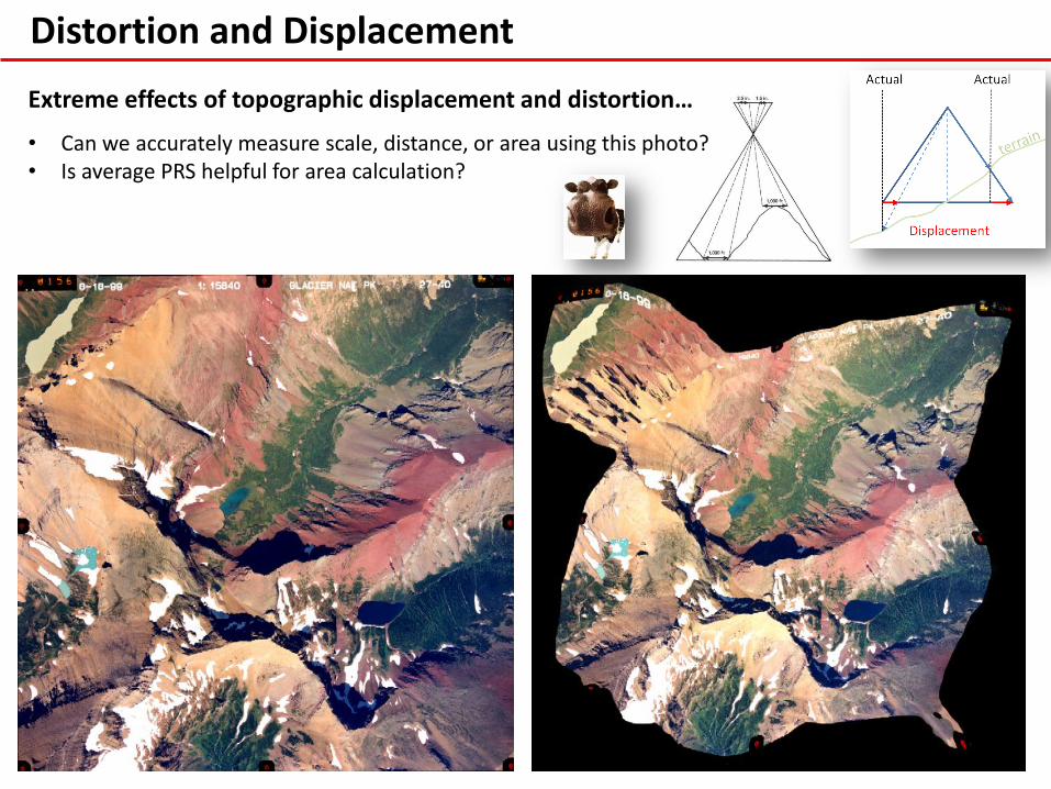
Extreme effects of topographic displacement and distortion…
• Can we accurately measure scale, distance, or area using this photo? • Is average PRS helpful for area calculation?

Displacement
On a vertical photograph over flat terrain…
• The farther any vertical object is from nadir…the greater the object’s top is displaced away from nadir
• The object’s bottom position remains stationary (i.e., no displacement)
However, Terrain Variation… • displaces both the top & bottom of
vertical objects.
• How much & direction (toward/away from Nadir) depends on magnitude of elev. ∆ (+/-) w/respect to Nadir elev.
Distortion and Displacement
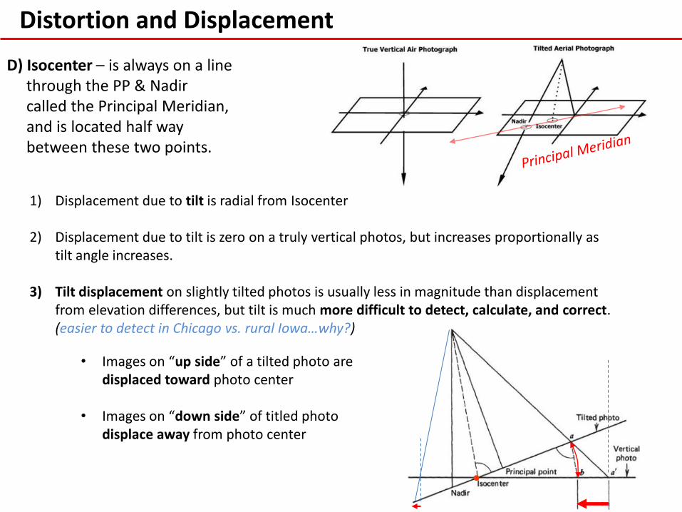
D) Isocenter – is always on a line through the PP & Nadir called the Principal Meridian, and is located half way between these two points.
1) Displacement due to tilt is radial from Isocenter
2) Displacement due to tilt is zero on a truly vertical photos, but increases proportionally as tilt angle increases.
3) Tilt displacement on slightly tilted photos is usually less in magnitude than displacement from elevation differences, but tilt is much more difficult to detect, calculate, and correct. (easier to detect in Chicago vs. rural Iowa…why?)
• Images on “up side” of a tilted photo are displaced toward photo center
• Images on “down side” of titled photo displace away from photo center
Topographic Displacement
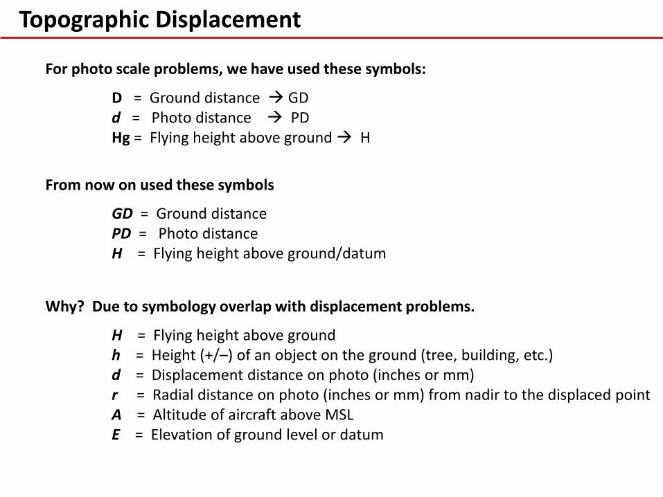
For photo scale problems, we have used these symbols:
D = Ground distance GD d = Photo distance PD Hg = Flying height above ground H
From now on used these symbols
GD = Ground distance PD = Photo distance H = Flying height above ground/datum
Why? Due to symbology overlap with displacement problems.
H = Flying height above ground h = Height (+/–) of an object on the ground (tree, building, etc.) d = Displacement distance on photo (inches or mm) r = Radial distance on photo (inches or mm) from nadir to the displaced point A = Altitude of aircraft above MSL E = Elevation of ground level or datum

Displacement: All about Similar Triangles
Displacement ( d )
d = r – r’ Consider following relationships: f r as H-h R f r’ as H R
MSL
Since d = r – r’ We have to solve for r and r’ separately…
In this Example…
r = photo dist.: nadir to building top
r’ = photo dist.: nadir to building base
d = displacement dist.: top – base r – r’

Topographic Displacement: All about Similar Triangles
𝑓
𝑟=
𝐻 − ℎ
𝑅 ∴ 𝑟 =
𝑓(𝑅)
𝐻 − ℎ
𝑓
𝑟′=
𝐻
𝑅 ∴ 𝑟′ =
𝑓(𝑅)
𝐻
𝑑 = 𝑟 − 𝑟′
𝑑 =𝑓𝑅
𝐻−ℎ−
𝑓𝑅
𝐻
𝑑 =𝐻(𝑓𝑅)
𝐻(𝐻−ℎ)−
𝐻−ℎ 𝑓𝑅
𝐻 𝐻−ℎ
𝑑 =𝐻(𝑓𝑅)
𝐻(𝐻−ℎ)−
𝐻𝑓𝑅−ℎ𝑓𝑅
𝐻 ℎ−𝐻
𝑑 =𝐻𝑓𝑅 − 𝐻𝑓𝑅 + ℎ𝑓𝑅
𝐻(𝐻−ℎ)
𝑑 =ℎ𝑓𝑅
𝐻(𝐻−ℎ)
𝑑 =𝑟ℎ
𝐻
r
1
2
𝑑 = 𝑟 − 𝑟′
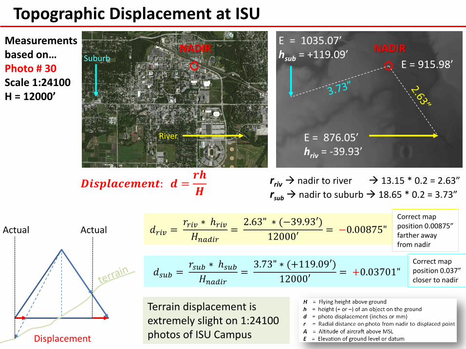
Topographic Displacement at ISU
NADIR
E = 915.98’
E = 1035.07’ hsub = +119.09’
E = 876.05’ hriv = -39.93’
rriv nadir to river 13.15 * 0.2 = 2.63”
rsub nadir to suburb 18.65 * 0.2 = 3.73”
𝑑𝑟𝑖𝑣 = 𝑟𝑟𝑖𝑣 ∗ ℎ𝑟𝑖𝑣
𝐻𝑛𝑎𝑑𝑖𝑟=
2.63" ∗ (−39.93′)
12000′= −0.00875"
𝑑𝑠𝑢𝑏 = 𝑟𝑠𝑢𝑏 ∗ ℎ𝑠𝑢𝑏
𝐻𝑛𝑎𝑑𝑖𝑟=
3.73" ∗ (+119.09′)
12000′= +0.03701"
𝑫𝒊𝒔𝒑𝒍𝒂𝒄𝒆𝒎𝒆𝒏𝒕: 𝒅 =𝒓𝒉
𝑯
Suburb
River
NADIR Measurements based on… Photo # 30 Scale 1:24100 H = 12000’
Correct map position 0.037” closer to nadir
Actual Actual
Displacement
Terrain displacement is extremely slight on 1:24100 photos of ISU Campus
Correct map position 0.00875” farther away from nadir
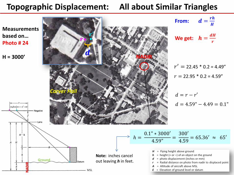
Topographic Displacement: All about Similar Triangles
𝑟′ = 22.45 * 0.2 = 4.49”
𝑟 = 22.95 * 0.2 = 4.59” 𝑑 = 𝑟 − 𝑟′
𝑑 = 4.59" − 4.49 = 0.1"
ℎ = 0.1" ∗ 3000′
4.59"=
300′
4.59= 65.36′ ≈ 65′
From: 𝒅 =𝒓𝒉
𝑯
We get: 𝒉 =𝒅𝑯
𝒓
NADIR
Measurements based on… Photo # 24 H = 3000’
Carver Hall
𝒓′ 𝒓
Note: inches cancel out leaving h in feet.
NA
DIR
Ground
𝒅

• Is this a truly “vertical” photograph? • How can one tell? • Where are the PP & Nadir points?
Tilt Displacement: Radial from Isocenter
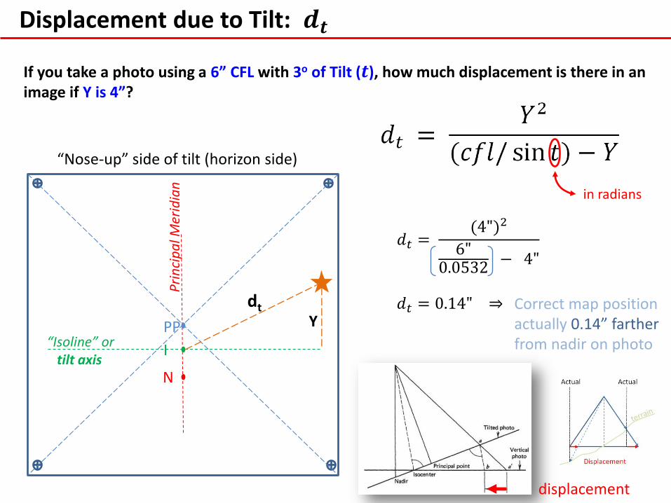
Displacement due to Tilt: 𝒅𝒕
“Nose-up” side of tilt (horizon side)
N
PP
I
Pri
nci
pa
l Mer
idia
n
“Isoline” or tilt axis
dt Y
If you take a photo using a 6” CFL with 3o of Tilt (𝒕), how much displacement is there in an image if Y is 4”?
𝑑𝑡 = (4")2
6"0.0532
− 4"
𝑑𝑡 = 0.14" ⇒
in radians
Correct map position actually 0.14” farther from nadir on photo
displacement

Tilt Displacement
On a tilted photograph, the nadir point was determined by intersecting lines passing through perfectly tall and clearly visible features on the photograph. The distance between the nadir & the principal point was measured to be 0.5 inches. What was the angle of tilt of the camera at the time of exposure if a 6 inch CFL lens was used?
𝑇𝑖𝑙𝑡 𝐴𝑛𝑔𝑙𝑒 𝜃 = 𝑡𝑎𝑛−1 0.5 𝑖𝑛.
6 𝑖𝑛. = 4.764𝑜
Nothing in radians!
𝑇𝑖𝑙𝑡 𝐴𝑛𝑔𝑙𝑒 𝜃 = 𝑡𝑎𝑛−1 |𝑃𝑃 − 𝑛𝑎𝑑𝑖𝑟|
𝐶𝐹𝐿

Another Topographic Displacement Problem
What can be done to make displacement as small as possible?
• The smaller the flying height or CFL, the greater the displacement.
• The taller the object (or deeper the hole) the more serious the displacement.
• Displacement is more serious the further we move from the nadir.
Suppose we fly at 13,750ft. and photograph a level terrain with a single 200ft. hill (above datum elev.)… How serious is photo displacement if 𝒓 = 𝟐. 𝟐𝟓“ and scale is 1:20,000?
𝒅 =𝒓𝒉
𝑯=
2.25" ∗ 200𝑓𝑡.
13,750𝑓𝑡.= 0.033“ …on the photo. What’s the ground distance?
𝐺𝐷 = 0.033" ∗ 20,000 ∗ 1′
12"= 55′

Another Height Problem
Rearrange displacement formula to get height formula as before…
𝑑 =𝑟ℎ
𝐻 ⇒ ℎ =
𝑑𝐻
𝑟
NOTE: 𝒉 formula only works when 𝒅 (i.e., 𝒓 & 𝒓′) is actually visible on the photo
Suppose we are using photos at a scale of 1:10,000. The flying height for the photos was 10,000 feet. The base of a building can be seen 3.16 inches (𝑟′)from the nadir. The top of the same building is 3.18 inches (𝑟) from the nadir. What is the height of the building?
𝒉 =𝒅𝑯
𝒓=
3.18"−3.16" ∗ 10000𝑓𝑡.
3.8"= 63𝑓𝑡.
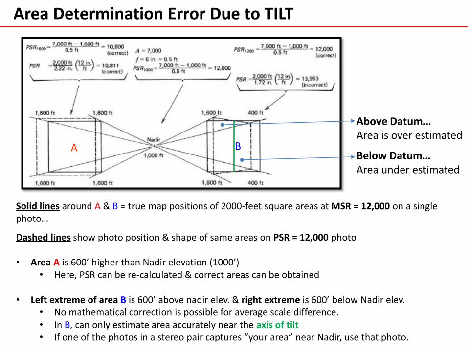
Solid lines around A & B = true map positions of 2000-feet square areas at MSR = 12,000 on a single photo…
Dashed lines show photo position & shape of same areas on PSR = 12,000 photo • Area A is 600’ higher than Nadir elevation (1000’)
• Here, PSR can be re-calculated & correct areas can be obtained
• Left extreme of area B is 600’ above nadir elev. & right extreme is 600’ below Nadir elev. • No mathematical correction is possible for average scale difference. • In B, can only estimate area accurately near the axis of tilt • If one of the photos in a stereo pair captures “your area” near Nadir, use that photo.
Above Datum… Area is over estimated
Below Datum… Area under estimated
Area Determination Error Due to TILT
A B

Effects of Topo Displacement on Area Determination
A more subtle example….

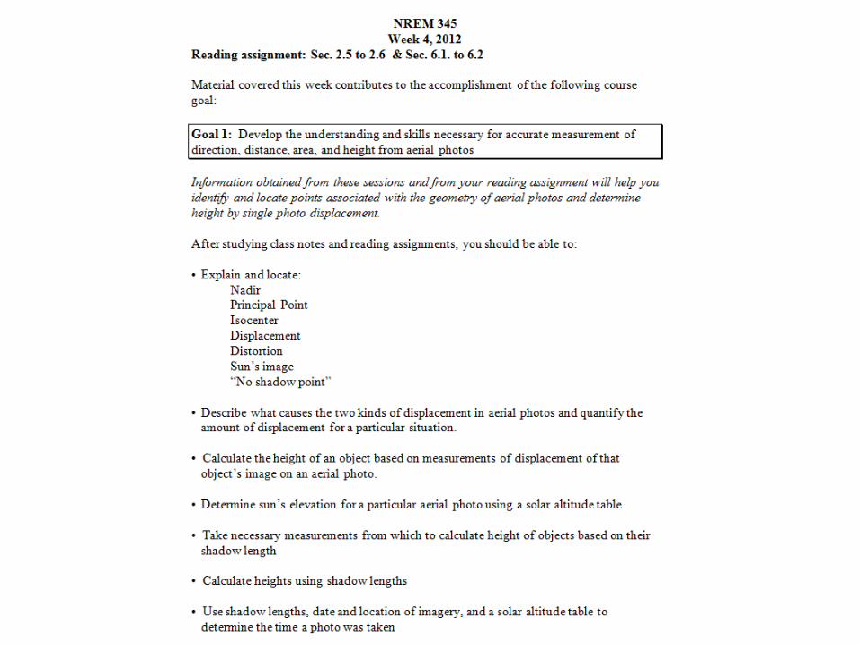
Week 4 Wednesday
Height Determination: The Shadow Method
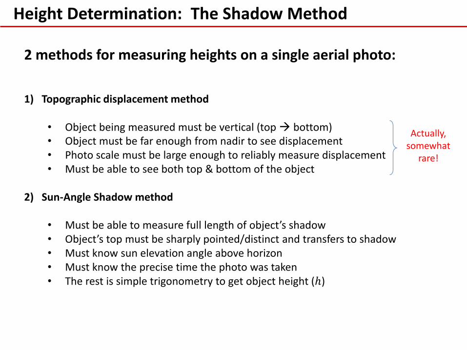
2 methods for measuring heights on a single aerial photo: 1) Topographic displacement method
• Object being measured must be vertical (top bottom) • Object must be far enough from nadir to see displacement • Photo scale must be large enough to reliably measure displacement • Must be able to see both top & bottom of the object
2) Sun-Angle Shadow method • Must be able to measure full length of object’s shadow • Object’s top must be sharply pointed/distinct and transfers to shadow • Must know sun elevation angle above horizon • Must know the precise time the photo was taken • The rest is simple trigonometry to get object height (ℎ)
Actually, somewhat
rare!

Height Determination: The Shadow Method
Not a trivial task to determine sun elevation angle! 1) Need the specific Lat/Lon of the object you wish to measure…
• Can be interpolated from 1:24000, 7.5 minute Topoquad maps • Can also use Google Earth or other GIS sources
2) Need the exact time of photo exposure • Photos we use in class have this info clipped off • The original still has it…
3) Need to plug time and location (Lat/Lon) into a Sun Elevation Calculator
or use solar altitude tables is info above is known. • http://www.esrl.noaa.gov/gmd/grad/solcalc/azel.html

Height Determination: The Shadow Method
Instances that lead to error in height estimation using tree shadows
Perfect! 1) Vertical 2) Pointy top
Shadow correct Shadow long Shadow long
Shadow short Shadow short Shadow long
Shadow top not resolved on photo
Shadow short Shadow short
Brush or snow

Height Determination: The Shadow Method
So, if all object conditions are met and we have all the photo ephemeris info… Then height by shadow measurement is a simple process:
Shadow Length
Object Height Sun Elevation Angle (𝜃)
𝑇𝑎𝑛 𝜃 = 𝑂𝑏𝑗𝑒𝑐𝑡 𝐻𝑒𝑖𝑔ℎ𝑡
𝑆ℎ𝑎𝑑𝑜𝑤 𝐿𝑒𝑛𝑔𝑡ℎ 𝐻𝑒𝑖𝑔ℎ𝑡 = 𝑇𝑎𝑛 𝜃 ∗ (𝑆ℎ𝑎𝑑𝑜𝑤 𝐿𝑒𝑛𝑔𝑡ℎ)
𝐹𝑖𝑟𝑠𝑡, 𝑐𝑜𝑛𝑣𝑒𝑟𝑡 𝜽 𝑓𝑟𝑜𝑚 𝑑𝑒𝑔𝑟𝑒𝑒𝑠 𝑡𝑜 𝑟𝑎𝑑𝑖𝑎𝑛𝑠 ⇒ 𝑑𝑒𝑔𝑟𝑒𝑒𝑠 ∗ 𝜋
180

Shadow Method: Determining Object Height
1) Begin by measuring the photo length (PD) of the shadow and converting that to a ground distance (GD) using the formula….
1
𝑃𝑆𝑅=
𝑃𝐷"
𝐺𝐷" ⇒ 𝑃𝑆𝑅 ∗ 𝑃𝐷" = GD“ ...GD" ∗
1′
12" = 𝐺𝐷′
2) Calculate the tangent of sun elevation angle & multiply by shadow length
Example: 1) You determine the shadow length of a radio tower is 200 ft.
2) You find that the sun elevation angle was 43o 43 ∗ 𝜋
180= 0.750492 radians
3) you find… 𝑇𝑎𝑛 0.750492 = 0.932515
4) With this, Height = 0.932515 ∗ 200 ft. = 𝟏𝟖𝟔. 𝟓 𝐟𝐭.
Shadow Method: Determining Sun Elevation
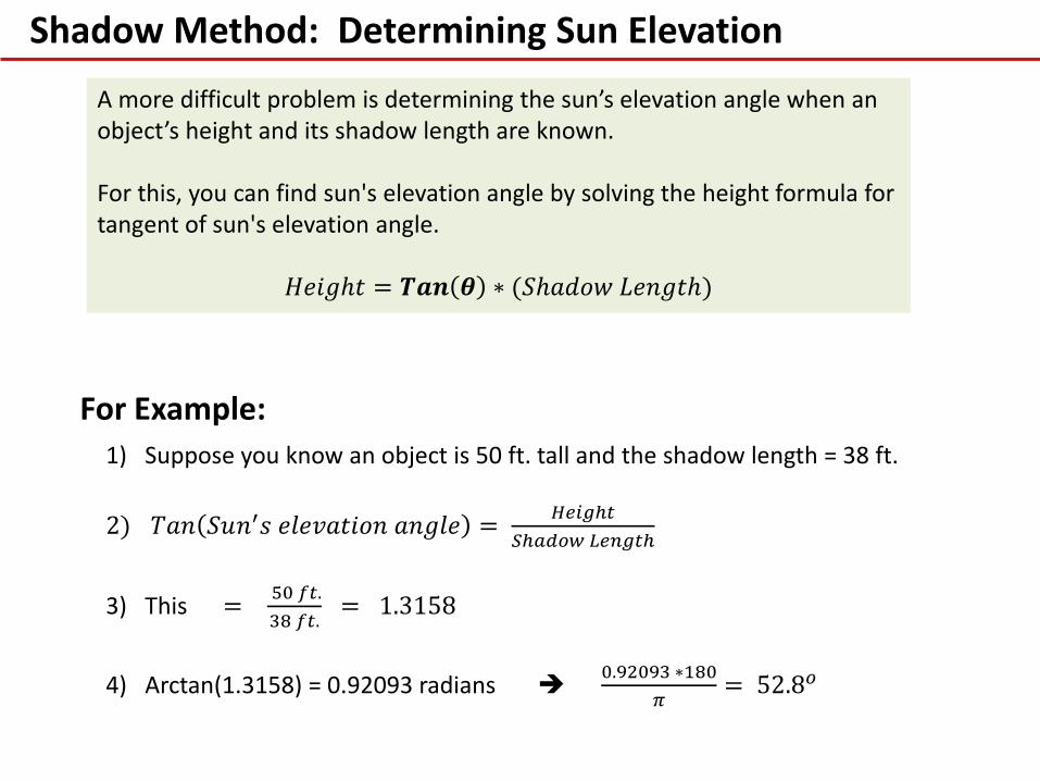
A more difficult problem is determining the sun’s elevation angle when an object’s height and its shadow length are known. For this, you can find sun's elevation angle by solving the height formula for tangent of sun's elevation angle.
𝐻𝑒𝑖𝑔ℎ𝑡 = 𝑻𝒂𝒏 𝜽 ∗ (𝑆ℎ𝑎𝑑𝑜𝑤 𝐿𝑒𝑛𝑔𝑡ℎ)
1) Suppose you know an object is 50 ft. tall and the shadow length = 38 ft.
2) 𝑇𝑎𝑛 𝑆𝑢𝑛′𝑠 𝑒𝑙𝑒𝑣𝑎𝑡𝑖𝑜𝑛 𝑎𝑛𝑔𝑙𝑒 = 𝐻𝑒𝑖𝑔ℎ𝑡
𝑆ℎ𝑎𝑑𝑜𝑤 𝐿𝑒𝑛𝑔𝑡ℎ
3) This = 50 𝑓𝑡.
38 𝑓𝑡. = 1.3158
4) Arctan(1.3158) = 0.92093 radians 0.92093 ∗180
𝜋= 52.8𝑜
For Example:

Most often, you won't know the height of objects casting shadows, so…
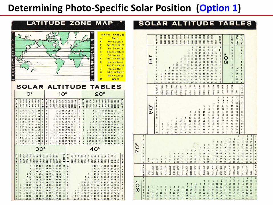
Options: 1) Can use a solar altitude table which is based on latitude (LAT) of the
photography & time the photo was taken.
• Will give an approximate value for sun's altitude depending on how closely LAT & time match those available in the table
• It is possible to interpolate the table for time, date, & LAT to get an exact answer for sun's altitude
2) Or, can use solar ephemeris to determine Sun’s altitude. To use ephemeris
must know the following:
• Angle X ….Sun’s declination (LAT) on the day of the photo (look up in ephemeris
• Angle Y ….LAT of photography (find this on a map) • Angle Z ….is the hour angle, or difference in longitude (LON) between
position of the sun and locality of the photography (can be calculated)
• 𝑆𝑖𝑛 𝐴𝑙𝑡. 𝐴𝑛𝑔𝑙𝑒 = 𝐶𝑜𝑠𝑋 𝐶𝑜𝑠𝑌 𝐶𝑜𝑠𝑍 + 𝒐𝒓 − 𝑆𝑖𝑛 𝑋 𝑆𝑖𝑛𝑌
+ from March 21 – Sept. 23 in Northern Hemisphere
– from Sept. 24 – March 20 in Southern Hemisphere
Determining Photo-Specific Solar Position
FYI only

Determining Photo-Specific Solar Position (Option 1)
Sun Position Calculator: http://aa.usno.navy.mil/data/docs/AltAz.php
output
Determining Photo-Specific Solar Position (Option 1)
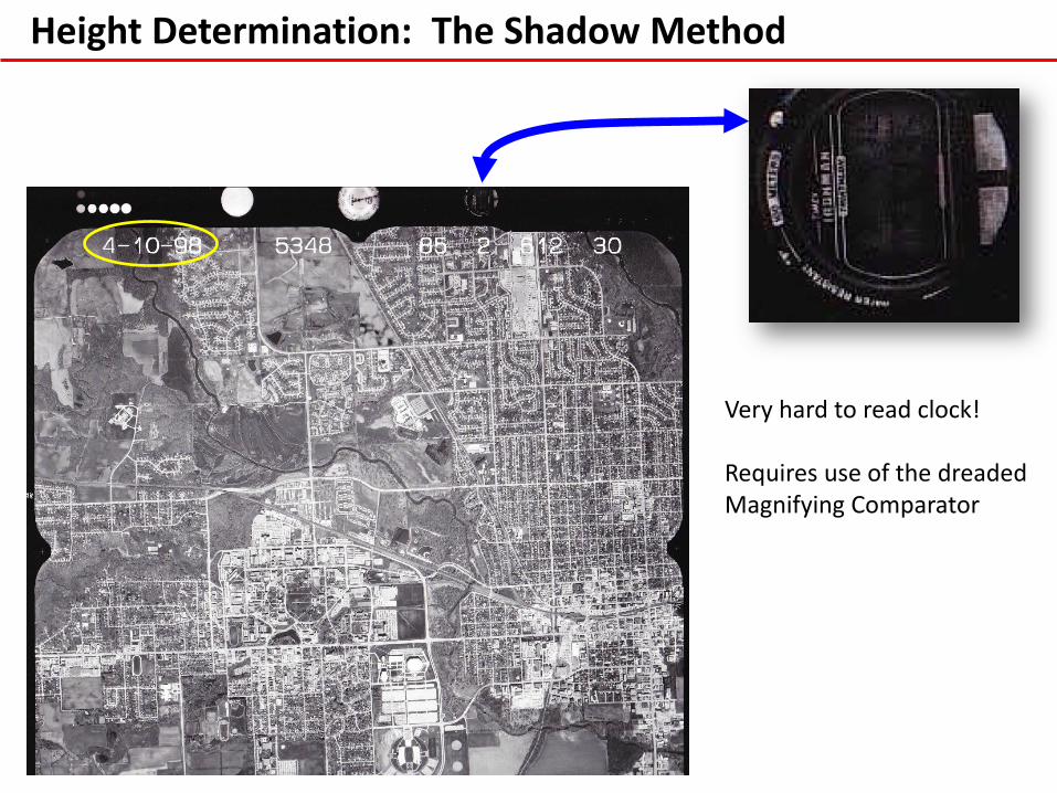
Height Determination: The Shadow Method
Very hard to read clock! Requires use of the dreaded Magnifying Comparator
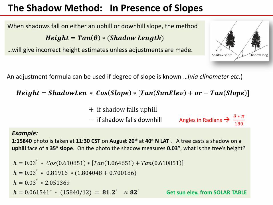
The Shadow Method: In Presence of Slopes
When shadows fall on either an uphill or downhill slope, the method
𝑯𝒆𝒊𝒈𝒉𝒕 = 𝑻𝒂𝒏 𝜽 ∗ (𝑺𝒉𝒂𝒅𝒐𝒘 𝑳𝒆𝒏𝒈𝒕𝒉)
…will give incorrect height estimates unless adjustments are made.
An adjustment formula can be used if degree of slope is known …(via clinometer etc.)
𝑯𝒆𝒊𝒈𝒉𝒕 = 𝑺𝒉𝒂𝒅𝒐𝒘𝑳𝒆𝒏 ∗ 𝑪𝒐𝒔 𝑺𝒍𝒐𝒑𝒆 ∗ [𝑻𝒂𝒏 𝑺𝒖𝒏𝑬𝒍𝒆𝒗 + 𝒐𝒓 − 𝑻𝒂𝒏 𝑺𝒍𝒐𝒑𝒆 ] + if shadow falls uphill
− if shadow falls downhill Angles in Radians 𝜃 ∗ 𝜋
180
Example: 1:15840 photo is taken at 11:30 CST on August 20st at 40o N LAT . A tree casts a shadow on a uphill face of a 35o slope. On the photo the shadow measures 0.03”, what is the tree’s height?
ℎ = 0.03" ∗ 𝐶𝑜𝑠 0.610851 ∗ 𝑇𝑎𝑛 1.064651 + 𝑇𝑎𝑛 0.610851
ℎ = 0.03" ∗ 0.81916 ∗ (1.804048 + 0.700186)
ℎ = 0.03" ∗ 2.051369
ℎ = 0.061541" ∗ (15840/12) = 𝟖𝟏. 𝟐′ ≈ 𝟖𝟐′ Get sun elev. from SOLAR TABLE
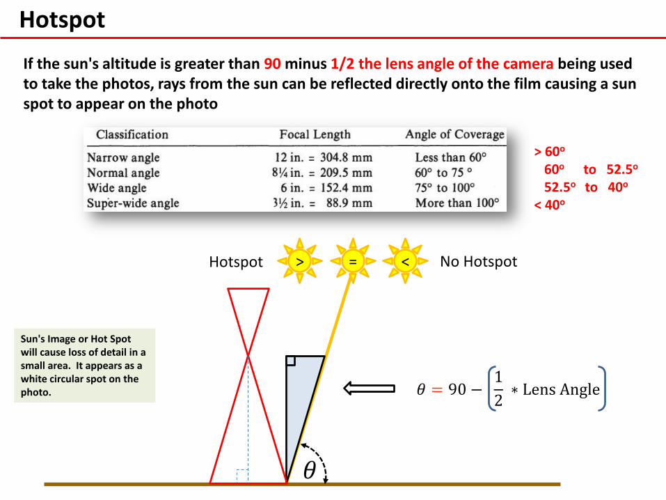
Hotspot
If the sun's altitude is greater than 90 minus 1/2 the lens angle of the camera being used to take the photos, rays from the sun can be reflected directly onto the film causing a sun spot to appear on the photo
> 60o
60o to 52.5o
52.5o to 40o
< 40o
𝜃 = 90 − 1
2 ∗ Lens Angle
=
𝜃
> < Hotspot No Hotspot
Sun's Image or Hot Spot will cause loss of detail in a small area. It appears as a white circular spot on the photo.
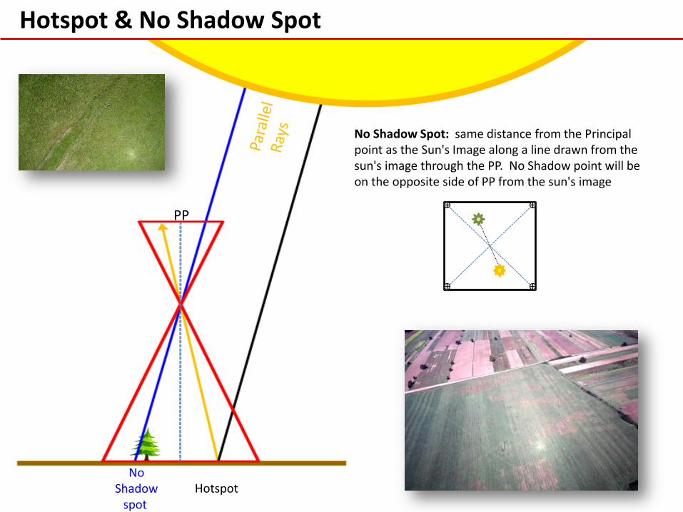
Hotspot & No Shadow Spot
PP
Hotspot No
Shadow spot
No Shadow Spot: same distance from the Principal point as the Sun's Image along a line drawn from the sun's image through the PP. No Shadow point will be on the opposite side of PP from the sun's image
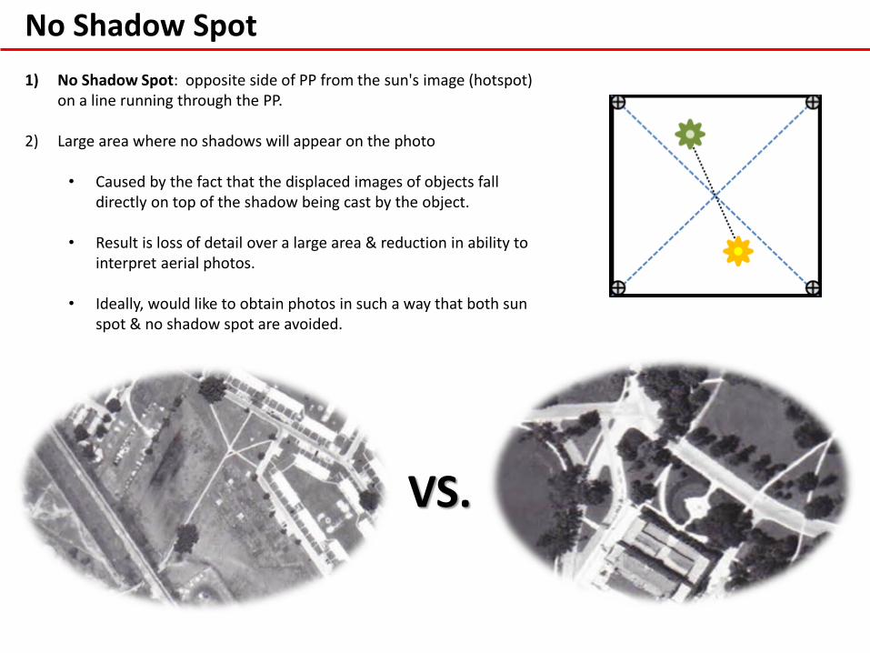
No Shadow Spot
1) No Shadow Spot: opposite side of PP from the sun's image (hotspot) on a line running through the PP.
2) Large area where no shadows will appear on the photo • Caused by the fact that the displaced images of objects fall
directly on top of the shadow being cast by the object.
• Result is loss of detail over a large area & reduction in ability to interpret aerial photos.
• Ideally, would like to obtain photos in such a way that both sun spot & no shadow spot are avoided.
VS.