Embed Size (px)
Citation preview
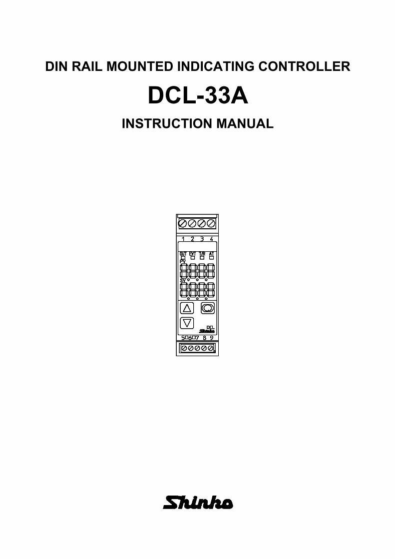
DIN RAIL MOUNTED INDICATING CONTROLLER
DCL-33AINSTRUCTION MANUAL

2
PrefaceThank you for purchasing our DIN Rail Mounted Indicating Controller DCL-33A. This manual containsinstructions for the mounting, functions, operations and notes when operating the DCL-33A. To ensure safeand correct use, thoroughly read and understand this manual before using this controller. To preventaccidents arising from the misuse of this controller, please ensure the operator receives this manual.
Notes• This instrument should be used in accordance with the specifications described in the manual.
If it is not used according to the specifications, it may malfunction or cause a fire.• Be sure to follow the warnings, cautions and notices. If they are not observed, serious injury or malfunction may
occur.• The contents of this instruction manual are subject to change without notice.• Care has been taken to ensure that the contents of this instruction manual are correct, but if there are any doubts,
mistakes or questions, please inform our sales department.• This instrument is designed to be installed on a DIN rail within a control panel. If it is not, measures must be taken
to ensure that the operator cannot touch power terminals or other high voltage sections.• Any unauthorized transfer or copying of this document, in part or in whole, is prohibited.• Shinko Technos Co., Ltd. is not liable for any damage or secondary damage(s) incurred as a result of using this
product, including any indirect damage.
Safety Precautions (Be sure to read these precautions before using our products.)
The safety precautions are classified into categories: “Warning” and “Caution”. Depending on circumstances,procedures indicated by Caution may result in serious consequences, so be sure to follow the directionsfor usage.
Warning
Warning• To prevent an electric shock or fire, only Shinko or other qualified service personnel may handle the inner
assembly.• To prevent an electric shock, fire or damage to the instrument, parts replacement may only be undertaken
by Shinko or other qualified service personnel.
Safety Precautions• To ensure safe and correct use, thoroughly read and understand this manual before using this instrument.
• This instrument is intended to be used for industrial machinery, machine tools and measuring equipment. Verify
correct usage after purpose-of-use consultation with our agency or main office. (Never use this instrument for
medical purposes with which human lives are involved.)
• External protection devices such as protective equipment against excessive temperature rise, etc. must be
installed, as malfunction of this product could result in serious damage to the system or injury to personnel. Also
proper periodic maintenance is required.
• This instrument must be used under the conditions and environment described in this manual. Shinko Technos
Co., Ltd. does not accept liability for any injury, loss of life or damage occurring due to the instrument being used
under conditions not otherwise stated in this manual.
Caution with respect to Export Trade Control Ordinance
To avoid this instrument from being used as a component in, or as being utilized in the manufacture of weapons
of mass destruction (i.e. military applications, military equipment, etc.), please investigate the end users and the
final use of this instrument. In the case of resale, ensure that this instrument is not illegally exported.
Caution
Procedures which may lead to dangerous conditions and cause death or seriousinjury, if not carried out properly.
Procedures which may lead to dangerous conditions and cause superficial to mediuminjury or physical damage or may degrade or damage the product, if not carried outproperly.

3
1. Installation Precautions
CautionThis instrument is intended to be used under the following environmental conditions(IEC61010-1): Overvoltage category , Pollution degree 2Ensure the mounting location corresponds to the following conditions:• A minimum of dust, and an absence of corrosive gases• No flammable, explosive gases• No mechanical vibrations or shocks• No exposure to direct sunlight, an ambient temperature of 0 to 50 (32 to 122 ) that does not changerapidly, and no icing
• An ambient non-condensing humidity of 35 to 85 %RH• No large capacity electromagnetic switches or cables through which large current is flowing.• No water, oil, chemicals or the vapors of these substances can come into direct contact with the unit.• Please note that the ambient temperature of this unit – not the ambient temperature of the controlpanel – must not exceed 50 (122 ) if mounted within a control panel, otherwise the life of electroniccomponents (especially electrolytic capacitors) may be shortened.
Note: Avoid setting this instrument directly on or near flammable material even though the case ofthis instrument is made of flame-resistant resin.
2. Wiring Precautions
Caution• Do not leave wire remnants in the instrument, because they could cause a fire or malfunction.• Use correct fitting ferrules with an insulation sleeve for the terminal screw when wiring the DCL-33A.• Tighten the terminal screw using the specified torque. If excessive force is applied to the screw whentightening, the terminal screw or case may be damaged.
• Do not apply a commercial power source to the sensor which is connected to the input terminal norallow the power source to come into contact with the sensor.
• This instrument does not have a power switch, circuit breaker and fuse. Therefore it is necessary toinstall a power switch, circuit breaker and fuse externally near the controller.(Recommended fuse: Time-lag fuse, rated voltage 250 V AC, rated current 2 A)
• For a 24 V AC/DC power source, do not confuse polarity when using direct current (DC).
3. Operation and Maintenance Precautions
Caution• It is recommended that auto-tuning be performed during the trial run.• Do not touch live terminals. This may cause an electric shock or problems in operation.• Turn the power supply to the instrument OFF before retightening the terminal or cleaning.
Working on or touching the terminal with the power switched ON may result in severe injury or deathdue to electrical shock.
• Use a soft, dry cloth when cleaning the instrument.(Alcohol based substances may tarnish or deface the unit.)
• As the display section is vulnerable, be careful not to put pressure on, scratch or strike it with a hard
object.
Characters used in this manual
Indication
Number, / -1 0 1 2 3 4 5 6 7 8 9
Indication
Alphabet A B C D E F G H I J K L M
Indication
Alphabet N O P Q R S T U V W X Y Z

4
Contents1. Model..................................................................................................................................................... 5
1.1 Model ............................................................................................................................................ 51.2 How to Read the Model Label ...................................................................................................... 5
2. Name and Functions of Controller ........................................................................................................ 6
3. Mounting to the Control Panel............................................................................................................... 73.1 Site Selection ................................................................................................................................. 73.2 External Dimensions (Scale: mm) ................................................................................................. 73.3 CT (Current transformer) External Dimensions (Scale: mm) ........................................................ 73.4 Mounting to and Removal from the DIN Rail................................................................................. 8
4. Wiring .................................................................................................................................................... 94.1 Terminal Arrangement................................................................................................................... 104.2 Heater Burnout Alarm Output (W option) ...................................................................................... 10
5. Setup ..................................................................................................................................................... 115.1 Main Setting Mode......................................................................................................................... 125.2 Sub Setting Mode .......................................................................................................................... 125.3 Auxiliary Function Setting Mode 1................................................................................................. 145.4 Auxiliary Function Setting Mode 2................................................................................................. 155.5 Auxiliary Function Setting Mode 3................................................................................................. 195.6 Output MV (manipulated variable) Indication................................................................................ 26
6. Simplified Converter Function............................................................................................................... 276.1 Fine Adjustment of Converter Output (4 to 20 mA DC) ................................................................ 286.2 Converter Setting Example ........................................................................................................... 29
7. Operation............................................................................................................................................... 30
8. Action Explanations.............................................................................................................................. 318.1 OUT1 Action.................................................................................................................................. 318.2 OUT1 ON/OFF Control Action ...................................................................................................... 318.3 Heater Burnout Alarm Action ........................................................................................................ 328.4 Alarm Action.................................................................................................................................. 328.5 OUT2 (Heating/Cooling Control) Action........................................................................................ 348.6 OUT2 (Heating/Cooling Control) Action (When Setting Overlap Band) ..................................... 358.7 OUT2 (Heating/Cooling Control) Action (When Setting Dead Band) ......................................... 36
9. AT (Auto-tuning) .................................................................................................................................... 37
10. Specifications...................................................................................................................................... 3810.1 Standard Specifications............................................................................................................... 3810.2 Optional Specifications................................................................................................................ 41
11. Troubleshooting .................................................................................................................................. 4411.1 Indication ..................................................................................................................................... 4411.2 Key Operation.............................................................................................................................. 4511.3 Control ......................................................................................................................................... 46
12. Character Table .................................................................................................................................. 4712.1 Main Setting Mode....................................................................................................................... 4712.2 Sub Setting Mode........................................................................................................................ 4712.3 Auxiliary Function Setting Mode 1............................................................................................... 4812.4 Auxiliary Function Setting Mode 2............................................................................................... 4912.5 Auxiliary Function Setting Mode 3............................................................................................... 51
Key Operation Flowchart............................................................................................................................ 55

5
1. Model1.1 Model
DCL - 3 3 A - , Series name: DCL-300 (W22.5 x H75 x D100mm)
Control action 3 PIDAlarm A Selectable by keypad *1
Control output OUT1
R Relay contact: 1aS Non-contact voltage (for SSR drive): 12 V DC 15%
A Direct current: 4 to 20 mA DCInput M Multi-range *2
Supply voltage100 to 240 V AC (standard)
1 24 V AC/DC *3
Option
W (5A) Heater burnout alarm output (5 A)W (10A) Heater burnout alarm output (10 A)W (20A) Heater burnout alarm output (20 A)W (50A) Heater burnout alarm output (50 A)DC Heating/Cooling control output OUT2C5 Serial communication EIA RS-485EA External setting inputEI Set value memory external selection
*1: Alarm type (12 types and No alarm action) and status Energized/De-energized can be selected by keypad.
*2: Thermocouple, RTD, Direct current and DC voltage can be selected by keypad.
*3: Standard supply voltage is 100 to 240 V AC. Enter “1” after the input code only when ordering 24 V AC/DC.
1.2 How to Read the Model LabelThe model label is attached to the right side of the case.
(e.g.) DCL-33A-R/M, C5, W (20 A)
①
②③④⑤⑥⑦⑧
No. Description Example
① Terminal arrangement DCL-33A-R/M, C5, W(20A) (*1)
② Model DCL-33A-R/M, C5, W(20A)
③ Option C5: Serial communication
W(20A): Heater burnout alarm (20 A) (*2)
④ Input MULTI-RANGE (Multi-range input)
⑤ Control output,
Event output
O1: 3 A 250 V AC (Control output OUT1)
EV: 0.1 A 24 V DC (Event output EV)
⑥ Power supply,
Power consumption
100 to 240 V AC, 50/60 Hz
5 VA
⑦ Recommended
ambient temperature
0 to 50
⑧ Serial number No. 15KF05000(*1) Terminal arrangement differs depending on the model.
(*2) For Heater burnout alarm output (W option), CT rated current is entered in bracket ( ).

6
2. Name and Functions of Controller
(Fig. 2-1)
No. Name Description
① EVT indicator
The red LED lights up when Event output [Alarm, Loop break alarm or Heater
burnout alarm (W option)] is ON.
The red LED also lights when control output OUT2 (DC option) is ON.
② OUT indicator
The green LED lights up when control output OUT1 is ON.
For direct current output, flashes in 125 ms cycles corresponding to the output
MV.
③ T/R indicatorThe yellow LED flashes during serial communication (C5 option) TX output
(transmitting).
④ AT indicator The yellow LED flashes while auto-tuning (AT) is performing.
⑤ PV DisplayIndicates the PV (process variable), or setting characters in setting mode with a
red LED.
⑥ SV DisplayIndicates the SV (desired value), output MV (manipulated variable) or the set value
in each setting mode with a green LED.
⑦ UP key Increases the numeric value.
⑧ DOWN key Decreases the numeric value.
⑨ MODE keySwitches the setting mode or registers the set data.
(Registers the set data by pressing the MODE key.)
⑩ SUB-MODE key
Enters Auxiliary function setting mode 2 in combination with the MODE key.
If ‘Control output OFF’ is selected in [SUB-MODE key function]: Turns all outputs
OFF as if the power were turned OFF.
If ‘Auto/Manual control’ is selected in [SUB-MODE key function]: Switches
Auto/Manual control.
If ‘Alarm HOLD cancel’ is selected in [SUB-MODE key function]: Cancels Alarm
HOLD.
CautionWhen setting the specifications and functions of this controller, connect mains power cable to terminals 1 and 2
first, then set them referring to “5. Setup” before performing “3. Mounting to the Control Panel” and “4. Wiring”.
①
②
⑤
⑥
③
④
⑦
⑧
⑨
⑩

7
3. Mounting to the Control Panel3.1 Site Selection
This instrument is intended to be used under the following environmental conditions(IEC61010-1): Overvoltage category , Pollution degree 2
Ensure the mounting location corresponds to the following conditions:• A minimum of dust, and an absence of corrosive gases• No flammable, explosive gases• Few mechanical vibrations or shocks• No exposure to direct sunlight, an ambient temperature of 0 to 50 (32 to 122 ) without rapidchange, and no icing
• An ambient non-condensing humidity of 35 to 85 %RH• No large capacity electromagnetic switches or cables through which large current is flowing• No water, oil, chemicals or the vapors of these substances can come into direct contact with the
controller.• Please note that the ambient temperature of this unit – not the ambient temperature of the control panel
– must not exceed 50 (122 ) if mounted within a control panel, otherwise the life of the electroniccomponents (especially electrolytic capacitors) may be shortened.
3.2 External Dimensions (Scale: mm)
(Fig. 3.2-1)
3.3 CT (Current transformer) External Dimensions (Scale: mm)
CTL-6-S-H (for 20 A) CTL-12-S36-10L1U (for 50 A)
(Fig. 3.3-1) (Fig. 3.3-2)
DIN rail

8
3.4 Mounting to and Removal from the DIN Rail
Caution• Mount the DIN rail horizontally.
When the DIN rail is mounted vertically, be sure to use commercially available fastening plates at
both ends of the DCL-33A series.
However, if the DIN rail is mounted horizontally in a position susceptible to vibration or shock, the
fastening plates must be used as well.
• To remove this instrument, a flat blade screwdriver is required for pulling down the lever.
Never turn the screwdriver when inserting it into the release lever.
If excessive power is applied to the lever, it may break.
• Recommended fastening plate
Manufacturer Model
Omron Corporation End plate PFP-M
IDEC Corporation Fastening plate BNL6
Panasonic Electric Works Co., Ltd. Fastening plate ATA4806
Mounting to the DIN rail (Fig. 3.4-1)
First, hook 1 of the DCL-33A on the upper side of the DIN rail.
Second, making 1 part of the DCL-33A as a support, fit the lower part 2 of the DCL-33A to the DIN
rail. DCL-33A will be completely fixed to DIN rail with a “Click” sound.
Removal from the DIN rail (Fig. 3.4-2)1 Insert a flat blade screwdriver into the release lever, and pull it down.2 The lock to the DIN rail will be released, then remove the unit from the DIN rail.
Be sure to hold onto the unit firmly, or it may drop to the ground.
(Fig. 3.4-1) Mounting (Fig. 3.4-2) Removal
1
2
12
Release lever

9
4. Wiring
WarningTurn the power supply to the instrument OFF before wiring or checking.
Working on or touching the terminal with the power switched ON may result in severe injury
or death due to electrical shock.
Caution• Do not leave wire remnants in the DCL-33A when wiring, because they could cause a fire or malfunction.
• Insert the connecting cable into the designated connector securely. Not doing so could cause
malfunction due to imperfect contact.
• Connect the AC power to the designated terminal as is written in this instruction manual. Otherwise it
may burn and damage the DCL-33A.
• Tighten the terminal screw using the specified torque. Excessive force could damage the terminal screw
and deface the case.
• Use a thermocouple and compensating lead wire that corresponds to the sensor input specification of this unit.
• Use the 3-wire RTD that corresponds to the sensor input specification of this unit.
• When using DC voltage and current inputs, be careful not to confuse polarity when wiring.
• For a 24 V DC power source, ensure polarity is correct.
• Keep input wires (Thermocouple, RTD, etc.) away from power source and load wires when wiring.
• Do not apply a commercial power source to the sensor connected to the input terminal nor allow the
power source to come into contact with the sensor.
• To prevent the unit from harmful effects of unexpected level noise, it is recommended that a surge
absorber be installed between the electromagnetic switch coils.
• This unit does not have a built-in power switch, circuit breaker and fuse. Therefore it is necessary to
install a power switch, circuit breaker and fuse externally near the controller.
(Recommended fuse: Time-lag fuse, Rated voltage 250 V AC, Rated current 2 A)
When using ferrules, use the following ferrules and crimping pliers made by Phoenix Contact GMBH & CO.
• Recommended ferrules and tightening torque
Terminal
number
Terminal
screw
Ferrules with
insulation sleeve
Conductor
cross sections
Tightening
torqueCrimping pliers
1 to 4 M2.6 AI 0.25-8 YE 0.2 to 0.25 mm2 0.5 to 0.6 N•m CRIMPFOX ZA3CRIMPFOX UD6AI 0.34-8 TQ 0.25 to 0.34 mm2
AI 0.5-8 WH 0.34 to 0.5 mm2
AI 0.75-8 GY 0.5 to 0.75 mm2
AI 1.0-8 RD 0.75 to 1.0 mm2
AI 1.5-8 BK 1.0 to 1.5 mm2
5 to 9 M2.0 AI 0.25-8 YE 0.2 to 0.25 mm2 0.22 to 0.25 N•m
AI 0.34-8 TQ 0.25 to 0.34 mm2
AI 0.5-8 WH 0.34 to 0.5 mm2

10
4.1 Terminal Arrangement
Bottom of the unit
CTEAEI
Communi-cation C5(RS-485)
(Fig. 4.1-1)
Name Description
PWR Power supply: 100 to 240 V AC or 24 V AC/DCFor 24 V DC, ensure polarity is correct.
O1 Control output OUT1
TC Thermocouple input
RTD Resistance temperature detector input
DC Direct current input, DC voltage input (*1)
EV Event outputOutputs when Alarm, Loop break alarm or Heater burnout alarm output (W option) is ON.
O2 Control output OUT2 [Heating/Cooling control output (DC option)]
RS-485 Serial communication (C5 option)
CT Current transformer input [Heater burnout alarm output (W option)]
EA External setting input (EA option)
EI Event input DI [Set value memory external selection (EI option)]
(*1) If direct current input (Externally mounted 50 shunt resistor) is designated, connect a 50 shunt resistor (sold
separately) between input terminals.
4.2 Heater Burnout Alarm Output (W option)
This alarm is not available for detecting current under phase control.
Use the current transformer (CT) provided, and pass one lead wire of the heater circuit into the hole of
the CT. When wiring, keep the CT wire away from any AC source or load wires to avoid the external
interference.
(Fig. 4.2-1)
CT input socket
Powersupply
Heater
CT
Solder the connector harness W wire to
CT terminals. (There is no polarity.)

11
5. SetupConnect mains power cable to terminals 1 and 2, and turn the power ON.
The PV Display indicates sensor input characters and temperature unit, and the SV Display indicates the
input range high limit value for approx. 3 seconds. (Table 5-1)
(If any other value is set in [Scaling high limit], the SV Display indicates the value.)
During this time all outputs and the LED indicators are in OFF status.
After that, the control starts, indicating PV (process variable) on the PV Display, and SV (desired value) on
the SV Display.
(Table 5-1)
Input Type Input Range Resolution
K–200 to 1370 –320 to 2500 1 ( )
–199.9 to 400.0 –199.9 to 750.0 0.1 ( )
J –200 to1000 –320 to1800 1 ( )
R 0 to 1760 0 to 3200 1 ( )
S 0 to 1760 0 to 3200 1 ( )
B 0 to 1820 0 to 3300 1 ( )
E –200 to 800 –320 to 1500 1 ( )
T –199.9 to 400.0 –199.9 to 750.0 0.1 ( )
N –200 to 1300 –320 to 2300 1 ( )
PL- 0 to 1390 0 to 2500 1 ( )
C (W/Re5-26) 0 to 2315 0 to 4200 1 ( )
Pt100–199.9 to 850.0 –199.9 to 999.9 0.1 ( )
–200 to 850 –300 to 1500 1 ( )
JPt100–199.9 to 500.0 –199.9 to 900.0 0.1 ( )
–200 to 500 –300 to 900 1 ( )
4 to 20 mA DC –1999 to 9999 (*1), (*2) 1
0 to 20 mA DC –1999 to 9999 (*1), (*2) 1
0 to 1 V DC –1999 to 9999 (*1) 1
0 to 5 V DC –1999 to 9999 (*1) 1
1 to 5 V DC –1999 to 9999 (*1) 1
0 to 10 V DC –1999 to 9999 (*1) 1
4 to 20 mA DC –1999 to 9999 (*1), (*3) 1
0 to 20 mA DC –1999 to 9999 (*1), (*3) 1
(*1) Input range and decimal point place can be changed.
(*2) Connect a 50 shunt resistor (sold separately) between input terminals.
(*3) This input type has a built-in shunt resistor (50 ).
12
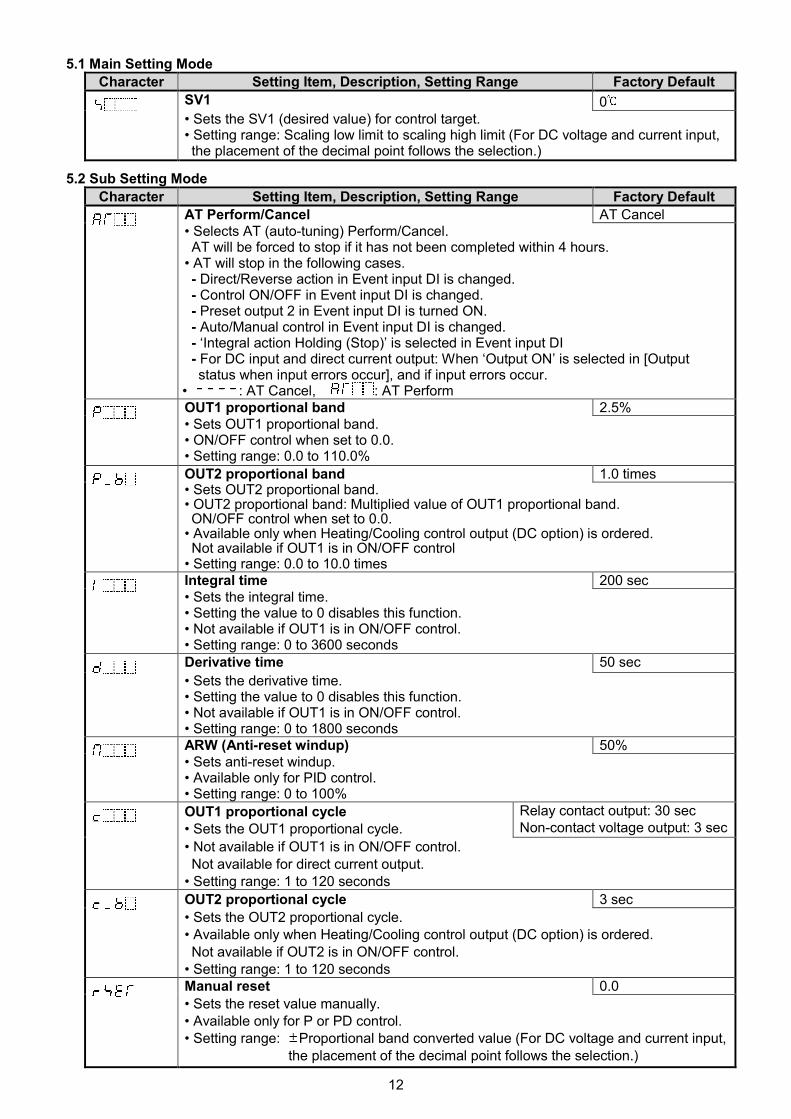
5.1 Main Setting Mode
Character Setting Item, Description, Setting Range Factory Default
SV1 0• Sets the SV1 (desired value) for control target.• Setting range: Scaling low limit to scaling high limit (For DC voltage and current input,the placement of the decimal point follows the selection.)
5.2 Sub Setting Mode
Character Setting Item, Description, Setting Range Factory Default
AT Perform/Cancel AT Cancel• Selects AT (auto-tuning) Perform/Cancel.AT will be forced to stop if it has not been completed within 4 hours.
• AT will stop in the following cases.- Direct/Reverse action in Event input DI is changed.- Control ON/OFF in Event input DI is changed.- Preset output 2 in Event input DI is turned ON.- Auto/Manual control in Event input DI is changed.- ‘Integral action Holding (Stop)’ is selected in Event input DI- For DC input and direct current output: When ‘Output ON’ is selected in [Outputstatus when input errors occur], and if input errors occur.
• : AT Cancel, : AT PerformOUT1 proportional band 2.5%• Sets OUT1 proportional band.• ON/OFF control when set to 0.0.• Setting range: 0.0 to 110.0%
OUT2 proportional band 1.0 times• Sets OUT2 proportional band.• OUT2 proportional band: Multiplied value of OUT1 proportional band.ON/OFF control when set to 0.0.
• Available only when Heating/Cooling control output (DC option) is ordered.Not available if OUT1 is in ON/OFF control
• Setting range: 0.0 to 10.0 timesIntegral time 200 sec• Sets the integral time.• Setting the value to 0 disables this function.• Not available if OUT1 is in ON/OFF control.• Setting range: 0 to 3600 secondsDerivative time 50 sec
• Sets the derivative time.• Setting the value to 0 disables this function.• Not available if OUT1 is in ON/OFF control.• Setting range: 0 to 1800 secondsARW (Anti-reset windup) 50%• Sets anti-reset windup.• Available only for PID control.• Setting range: 0 to 100%
OUT1 proportional cycle• Sets the OUT1 proportional cycle.
Relay contact output: 30 secNon-contact voltage output: 3 sec
• Not available if OUT1 is in ON/OFF control.Not available for direct current output.
• Setting range: 1 to 120 seconds
OUT2 proportional cycle 3 sec
• Sets the OUT2 proportional cycle.• Available only when Heating/Cooling control output (DC option) is ordered.Not available if OUT2 is in ON/OFF control.
• Setting range: 1 to 120 secondsManual reset 0.0
• Sets the reset value manually.• Available only for P or PD control.• Setting range: Proportional band converted value (For DC voltage and current input,
the placement of the decimal point follows the selection.)

13
Character Setting Item, Description, Setting Range Factory Default
Alarm 1 value 0
• Sets Alarm 1 action point.• Alarm 1 value matches Alarm 1 low limit alarm value in the following cases:When ‘High/Low limits independent alarm’, ‘High/Low limit range independent alarm’or ‘High/Low limits with standby independent alarm’ is selected in [Alarm 1 type].
• When Alarm, Loop break alarm and Heater burnout alarm (W option) are used
together, they utilize common output terminals.
• Not available if No alarm action is selected in [Alarm 1 type].
• Setting range: See (Table 5.2-1). (For DC voltage and current input, the placement of
the decimal point follows the selection.)
. and
XX.X
alternating
display
Heater burnout alarm value 0.0 A
• Sets the heater current value for Heater burnout alarm.
• Setting the value to 0.0 disables Heater burnout alarm action.
• Upon returning to set limits, the alarm will stop.
When Heater burnout alarm, Alarm and Loop break alarm are used together, they
utilize common output terminals.
• Available only when Heater burnout alarm (W option) is ordered.
• Rated current 5 A: 0.0 to 5.0 A
Rated current 10A: 0.0 to10.0 A
Rated current 20A: 0.0 to 20.0 A
Rated current 50A: 0.0 to 50.0 A
Loop break alarm time 0 minutes
• Sets the time to assess the Loop break alarm. (See “Loop break alarm” on p.18.)
• Setting the value to 0 disables Loop break alarm.
• When Loop break alarm, Alarm and Heater burnout alarm are used together, they
utilize common output terminals.
• Setting range: 0 to 200 minutes
Loop break alarm span 0
• Sets the span to assess the Loop break alarm. (See “Loop break alarm” on p.18.)
• Setting the value to 0 disables Loop break alarm.
• When Loop break alarm, Alarm and Heater burnout alarm are used together, they
utilize common output terminals.
• Setting range: Thermocouple, RTD input: 0 to 150 ( ) or 0.0 to 150.0 ( )
DC voltage, current input: 0 to 1500 (The placement of the decimal point follows the
selection.)
(Table 5.2-1)
Alarm type Setting range
High limit alarm –(Scaling span) to scaling span Minimumnegative value:–199.9 or –1999
Maximumpositive value:999.9 or 9999
Low limit alarm –(Scaling span) to scaling span
High/Low limits alarm 0 to scaling span
High/Low limit range alarm 0 to scaling span
Process high alarm Scaling low limit value to scaling high limit value
Process low alarm Scaling low limit value to scaling high limit value
High limit with standby alarm –(Scaling span) to scaling span
Low limit with standby alarm –(Scaling span) to scaling span
High/Low limits with standby alarm 0 to scaling span
High/Low limits independent alarm 0 to scaling span
High/Low limit rangeindependent alarm
0 to scaling span
High/Low limits with standbyindependent alarm
0 to scaling span

14
5.3 Auxiliary Function Setting Mode 1
Character Setting Item, Description, Setting Range Factory Default
Set value lock Unlock
• Locks the set values to prevent setting errors.The setting item to be locked depends on the selection.
• Auto-tuning (AT) cannot be carried out if Lock 1 or Lock 2 is selected.• (Unlock): All set values can be changed.
(Lock 1): None of the set values can be changed.(Lock 2): Only main setting mode can be changed.(Lock 3): All set values – except input type and Controller/Converter – can be
changed. However, changed values revert to their previous valuesafter power is turned off because they are not saved in thenon-volatile memory.Do not change any setting item in Auxiliary function setting mode 2.If any item in Auxiliary function setting mode 2 is changed, it willaffect other setting items such as the SV and Alarm value.Be sure to select Lock 3 when changing the set value frequently viasoftware communication. (If a value set by the softwarecommunication is the same as the value before the setting, thevalue will not be written in non-volatile memory.)
Sensor correction 0.0• Sets the sensor correction value. (For details, see ‘Sensor correction function’ on p.18.)• Setting range: Thermocouple, RTD input: –100.0 to 100.0 ( )
DC voltage, current input: –1000 to 1000 (The placement of the decimalpoint follows the selection.)
Communication protocol Shinko protocol• Selects communication protocol.• Available only when serial communication (C5 option) is ordered.• : Shinko protocol
: Modbus ASCII mode
: Modbus RTU mode: Shinko protocol (Block read available): Modbus ASCII mode (Block read available): Modbus RTU mode (Block read available)
Instrument number 0• Sets an individual instrument number for each DCL-33A when connecting multiple
DCL-33A units in serial communication.• Available only when serial communication (C5 option) is ordered.• Setting range: 0 to 95Communication speed 9600 bps• Selects the speed in accordance with the host computer.• Available only when serial communication (C5 option) is ordered.• : 2400 bps
: 4800 bps: 9600 bps: 19200 bps: 38400 bps
Parity Even• Selects the parity.• Available only when serial communication (C5 option) is ordered.Not available if Shinko protocol is selected in [Communication protocol].
• : No parity: Even: Odd
Stop bit 1
• Selects the stop bit.• Available only when serial communication (C5 option) is ordered.
Not available if Shinko protocol is selected in [Communication protocol].• Selection: 1 or 2

15
5.4 Auxiliary Function Setting Mode 2
Character Setting Item, Description, Setting Range Factory Default
Input type K (–200 to 1370 )
• Selects a sensor type and temperature unit from thermocouple (10 types),RTD (2 types), Direct current (4 types) and DC voltage (4 types) and / .
• When changing input from DC voltage to other inputs, detach the sensorconnected to this controller, then change the input. The input circuit may breakif the input is changed with the sensor connected.
K –200–199.9
J –200R 0S 0B 0E –200T –199.9N –200PL- 0C (W/Re5-26) 0Pt100 –199.9JPt100 –199.9Pt100 –200JPt100 –200
tototototototototototototototo
1370400.01000176017601820800
400.0130013902315
850.0500.0
850500
K –320–199.9
J –320R 0S 0B 0E –320T –199.9N –320PL- 0C (W/Re5-26) 0Pt100 –199.9JPt100 –199.9Pt100 –300JPt100 –300
tototototototototototototototo
2500750.018003200320033001500750.0230025004200999.9900.01500900
4 to 20 mA –1999 to 9999 (Externally mounted 50 shunt resistor)0 to 20 mA –1999 to 9999 (Externally mounted 50 shunt resistor)
0 to 1 V –1999 to 99990 to 5 V –1999 to 99991 to 5 V –1999 to 99990 to 10 V –1999 to 99994 to 20 mA –1999 to 9999 (Built-in 50 shunt resistor)0 to 20 mA –1999 to 9999 (Built-in 50 shunt resistor)
Scaling high limit 1370
• Sets the scaling high limit value.• Setting range: Scaling low limit to input range high limit(For DC voltage, current input, the placement of the decimal point follows the selection.)
Scaling low limit –200
• Sets the scaling low limit value.• Setting range: Input range low limit to scaling high limit(For DC voltage, current input, the placement of the decimal point follows the selection.)
Decimal point place No decimal point
• Selects the decimal point place.Not available if thermocouple or RTD is selected in [input type].
• : No decimal point: 1 digit after decimal point: 2 digits after decimal point: 3 digits after decimal point
PV filter time constant 0.0 sec
• Sets the PV filter time constant.If the set value is too large, it affects control results due to the response delay.
• Setting range: 0.0 to 10.0 seconds
OUT1 high limit 100%
• Sets the OUT1 high limit value.• Available for direct current output. Not available if OUT1 is in ON/OFF control.• Setting range: OUT1 low limit value to 100%
(Direct current output type: OUT1 low limit value to 105%)
16
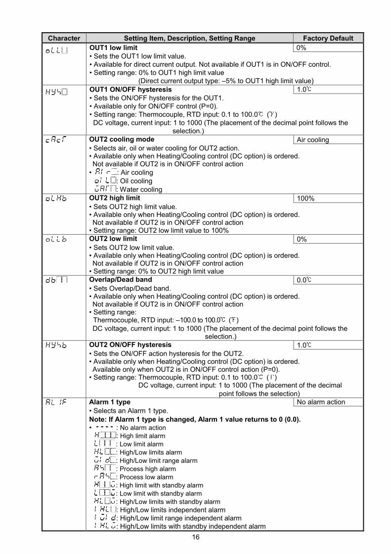
Character Setting Item, Description, Setting Range Factory Default
OUT1 low limit 0%• Sets the OUT1 low limit value.• Available for direct current output. Not available if OUT1 is in ON/OFF control.• Setting range: 0% to OUT1 high limit value
(Direct current output type: –5% to OUT1 high limit value)OUT1 ON/OFF hysteresis 1.0• Sets the ON/OFF hysteresis for the OUT1.• Available only for ON/OFF control (P=0).• Setting range: Thermocouple, RTD input: 0.1 to 100.0 ( )DC voltage, current input: 1 to 1000 (The placement of the decimal point follows the
selection.)OUT2 cooling mode Air cooling• Selects air, oil or water cooling for OUT2 action.• Available only when Heating/Cooling control (DC option) is ordered.Not available if OUT2 is in ON/OFF control action
• : Air cooling: Oil cooling: Water cooling
OUT2 high limit 100%• Sets OUT2 high limit value.• Available only when Heating/Cooling control (DC option) is ordered.Not available if OUT2 is in ON/OFF control action
• Setting range: OUT2 low limit value to 100%OUT2 low limit 0%• Sets OUT2 low limit value.• Available only when Heating/Cooling control (DC option) is ordered.Not available if OUT2 is in ON/OFF control action
• Setting range: 0% to OUT2 high limit valueOverlap/Dead band 0.0• Sets Overlap/Dead band.• Available only when Heating/Cooling control (DC option) is ordered.Not available if OUT2 is in ON/OFF control action
• Setting range:Thermocouple, RTD input: –100.0 to 100.0 ( )DC voltage, current input: 1 to 1000 (The placement of the decimal point follows the
selection.)OUT2 ON/OFF hysteresis 1.0• Sets the ON/OFF action hysteresis for the OUT2.• Available only when Heating/Cooling control (DC option) is ordered.Available only when OUT2 is in ON/OFF control action (P=0).
• Setting range: Thermocouple, RTD input: 0.1 to 100.0 ( )DC voltage, current input: 1 to 1000 (The placement of the decimal
point follows the selection)Alarm 1 type No alarm action
• Selects an Alarm 1 type.Note: If Alarm 1 type is changed, Alarm 1 value returns to 0 (0.0).• : No alarm action
: High limit alarm
: Low limit alarm
: High/Low limits alarm
: High/Low limit range alarm
: Process high alarm
: Process low alarm
: High limit with standby alarm
: Low limit with standby alarm
: High/Low limits with standby alarm
: High/Low limits independent alarm: High/Low limit range independent alarm: High/Low limits with standby independent alarm
17
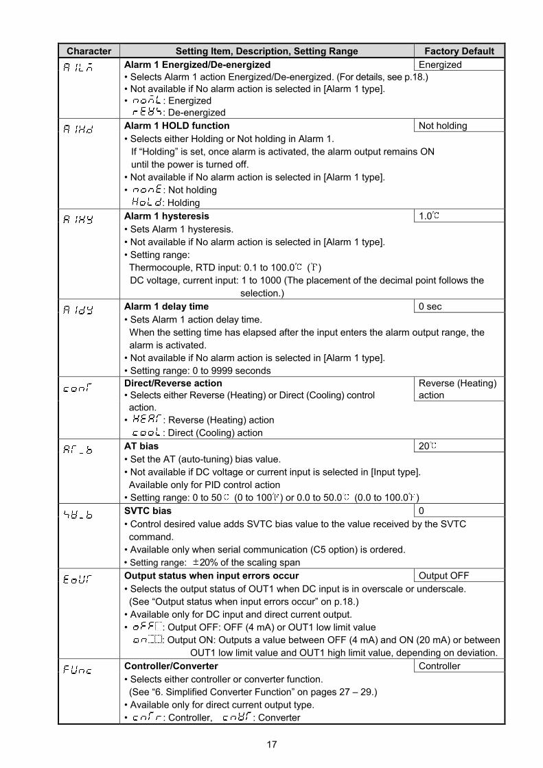
Character Setting Item, Description, Setting Range Factory Default
Alarm 1 Energized/De-energized Energized
• Selects Alarm 1 action Energized/De-energized. (For details, see p.18.)• Not available if No alarm action is selected in [Alarm 1 type].• : Energized
: De-energized
Alarm 1 HOLD function Not holding
• Selects either Holding or Not holding in Alarm 1.
If “Holding” is set, once alarm is activated, the alarm output remains ON
until the power is turned off.
• Not available if No alarm action is selected in [Alarm 1 type].
• : Not holding
: Holding
Alarm 1 hysteresis 1.0
• Sets Alarm 1 hysteresis.
• Not available if No alarm action is selected in [Alarm 1 type].
• Setting range:
Thermocouple, RTD input: 0.1 to 100.0 ( )
DC voltage, current input: 1 to 1000 (The placement of the decimal point follows the
selection.)
Alarm 1 delay time 0 sec
• Sets Alarm 1 action delay time.
When the setting time has elapsed after the input enters the alarm output range, the
alarm is activated.
• Not available if No alarm action is selected in [Alarm 1 type].
• Setting range: 0 to 9999 seconds
Direct/Reverse action• Selects either Reverse (Heating) or Direct (Cooling) control
Reverse (Heating)action
action.
• : Reverse (Heating) action
: Direct (Cooling) action
AT bias 20
• Set the AT (auto-tuning) bias value.
• Not available if DC voltage or current input is selected in [Input type].
Available only for PID control action
• Setting range: 0 to 50 (0 to 100 ) or 0.0 to 50.0 (0.0 to 100.0 )
SVTC bias 0
• Control desired value adds SVTC bias value to the value received by the SVTC
command.
• Available only when serial communication (C5 option) is ordered.
• Setting range: 20% of the scaling span
Output status when input errors occur Output OFF
• Selects the output status of OUT1 when DC input is in overscale or underscale.
(See “Output status when input errors occur” on p.18.)
• Available only for DC input and direct current output.
• : Output OFF: OFF (4 mA) or OUT1 low limit value
: Output ON: Outputs a value between OFF (4 mA) and ON (20 mA) or between
OUT1 low limit value and OUT1 high limit value, depending on deviation.
Controller/Converter Controller
• Selects either controller or converter function.
(See “6. Simplified Converter Function” on pages 27 – 29.)
• Available only for direct current output type.
• : Controller, : Converter

18
Sensor correction functionThis corrects the input value from the sensor. When a sensor cannot be set at the exact location wherecontrol is desired, the sensor-measured temperature may deviate from the temperature in the controlledlocation.When using multiple controllers, sometimes the measured temperatures (input value) do not match(even if SV is the same value) due to differences in sensor accuracy or dispersion of load capacities.In such a case, the control can be set at the desired temperature by adjusting the input value of sensors.However, it is effective within the input rated range regardless of the sensor correction value.PV after sensor correction = Current PV + (Sensor correction value)
Loop break alarmThe alarm will be activated if the PV (process variable) does not reach the Loop break alarm spansetting within the time allotted to assess the Loop break alarm after the MV (manipulated variable) hasreached 100% or the control output high limit value. The alarm will also be activated if the PV (processvariable) does not drop to the Loop break alarm span setting within the time allotted to assess the Loopbreak alarm after the MV has reached 0% or the control output low limit value.When the control action is Direct (Cooling), read “drop to” for “reach” and vice versa.
Energized/De-energized[If alarm action Energized is selected]When the alarm output indicator is lit, the alarm output (between terminals 8 and 9) is conducted (ON).When the alarm output indicator is unlit, the alarm output is not conducted (OFF).
[If alarm action De-energized is selected]When the alarm output indicator is lit, the alarm output (between terminals 8 and 9) is not conducted (OFF).When the alarm output indicator is unlit, the alarm output is conducted (ON).
High limit alarm (Energized setting) High limit alarm (De-energized setting)
(Fig. 5.4-1) (Fig. 5.4-2)
Output status when input errors occurControl output status differs depending on the selection in [Output status when input errors occur] asfollows.
Output status
when input
errors occur
(*1)
Contents
and
Indication
Output status
Controller/Converter
Controller Converter
OUT1 OUT2 OUT1
Direct action Reverse action Direct Reverse Direct Reverse
“ ”flashes.
ON (20 mA)or OUT1 highlimit value (*2)
OFF (4 mA)orOUT1 low limitvalue
OUT2low limit value
20 mAorOUT1high limitvalue
4 mAorOUT1low limitvalue
OFF (4 mA)or OUT1 lowlimit value
“ ”flashes.
OFF (4 mA)orOUT1 lowlimit value
ON (20 mA) orOUT1 high limitvalue (*2) OUT2
low limit value
4 mAorOUT1low limitvalue
20 mAorOUT1high limitvalue
OFF (4 mA) orOUT1 low limitvalue
(*1) [Output status when input errors occur] can be used only for controllers using direct current and voltageinputs, and direct current output.If OUT1 is not Direct current output, the output status will be the same as when is selected in[Output status when input errors occur].For manual control, the preset MV is output.
(*2) Outputs a value between OFF (4 mA) and ON (20 mA) or between OUT1 low limit value and OUT1high limit value, depending on deviation.
OFF
ON
Alarm hysteresis
+ Alarm value
OFF
ON
+ Alarm value
Alarm hysteresis
SV SV

19
5.5 Auxiliary Function Setting Mode 3
Character Setting Item, Description, Setting Range Factory Default
Event input DI allocation No event
• Selects Event input DI function from the following.
• Available only when Set value memory external selection (EI option) is selected.
Event Input FunctionInput ON
(Closed)
Input OFF
(Open)Remarks
No event
Set value memory SV2 SV1 SV1/SV2
selectable
Control ON/OFF (*1) Control OFF Control ON Control ON/OFF
selectable
Direct/Reverse action Direct Reverse Direct/Reverse
control selectable
Preset output 1 ON/OFF Preset output Usual control If sensor is burnt
out, the unit
maintains control
with the preset
MV.
Preset output 2 ON/OFF Preset output Usual control The unit
maintains control
with the preset
MV.
Auto/Manual control (*2) Manual Automatic Auto/Manual
control selectable
Integral action Holding
(Stop)/Usual integral
action
Integral action
Holding(Stop)
Usual integral
action
Control continues
with the integral
value being held.
Set value memory SV1 SV2
Control ON/OFF (*1) Control ON Control OFF
Direct/Reverse action Reverse Direct
Preset output 1 ON/OFF Usual control Preset output
Preset output 2 ON/OFF Usual control Preset output
Auto/Manual control (*2) Automatic Manual
Integral action Holding
(Stop)/Usual integral
action
Usual integral
action
Integral action
Holding (Stop)
to : Selected functions work when Event input DI is closed.
to : Selected functions work when Event input DI is open.
(*1) When selecting Control ON/OFF, if ‘Control output OFF’ has not been selected
in [SUB-MODE key function], Event input DI allocation will return to No event.
(*2) When selecting Auto/Manual control, if ‘Auto/Manual control’ has not been selected
in [SUB-MODE key function], Event input DI allocation will return to No event.
SV2 0
• Sets SV2 (the 2nd desired value).
• Available when Set value memory external selection (EI option) is ordered.
• Available when 001 or 008 is selected in [Event input DI allocation].
• Setting range: Scaling low limit to Scaling high limit

20
Character Setting Item, Description, Setting Range Factory Default
Alarm 1 value 0 Enabled/Disabled Disabled
• Selects Alarm 1 action Enabled or Disabled when Alarm 1 value is 0 (zero).
• Not available if No alarm action is selected in [Alarm 1 type].
• Invalidated for Process alarm
• : Disabled
: Enabled
Alarm 1 high limit alarm value 0
• Sets Alarm 1 high limit alarm value.
• Available when ‘High/Low limits independent alarm’, ‘High/Low limit range independent
alarm’ or ‘High/Low limits with standby independent alarm’ is selected in [Alarm 1 type].
• Setting range: See (Table 5.2-1) on p.13. (For DC voltage and current input, the
placement of the decimal point follows the selection)
Alarm 2 type No alarm action
• Selects an Alarm 2 type.
Note: If Alarm 2 type is changed, Alarm 2 value returns to 0 (0.0).
• : No alarm action
: High limit alarm
: Low limit alarm
: High/Low limits alarm
: High/Low limit range alarm
: Process high alarm
: Process low alarm
: High limit with standby alarm
: Low limit with standby alarm
: High/Low limits with standby alarm
: High/Low limits independent alarm
: High/Low limit range independent alarm
: High/Low limits with standby independent alarm
Alarm 2 value 0 Enabled/Disabled Disabled
• Selects Alarm 2 action Enabled or Disabled when Alarm 2 value is 0 (zero).
• Not available if No alarm action is selected in [Alarm 2 type].
• Invalidated for Process alarm
• : Disabled
: Enabled
Alarm 2 value 0
• Sets Alarm 2 action point.
• Alarm 2 value matches Alarm 2 low limit alarm value in the following cases:
When ‘High/Low limits independent alarm’, ‘High/Low limit range independent alarm’
or ‘High/Low limits with standby independent alarm’ is selected in [Alarm 2 type].
• When Alarm, Loop break alarm and Heater burnout alarm are used together, they
utilize common output terminals.
• Not available if No alarm action is selected in [Alarm 2 type].
• Setting range: See (Table 5.2-1) on p.13. (For DC voltage and current input, the
placement of the decimal point follows the selection.)
Alarm 2 high limit alarm value 0
• Sets Alarm 2 high limit alarm value.
• Available when ‘High/Low limits independent alarm’, ‘High/Low limit range independent
alarm’ or ‘High/Low limits with standby independent alarm’ is selected in [Alarm 2 type].
• Setting range: See (Table 5.2-1) on p.13. (For DC voltage and current input, the
placement of the decimal point follows the selection)

21
Character Setting Item, Description, Setting Range Factory Default
Alarm 2 Energized/De-energized Energized
• Selects Alarm 2 action Energized/De-energized. (For details, see p.18.)
• Not available if No alarm action is selected in [Alarm 2 type].
• : Energized
: De-energized
Alarm 2 HOLD function Not holding
• Selects either Holding or Not holding in Alarm 2.
When “Holding” is set, once alarm is activated, the alarm output remains ON
until the power is turned off.
• Not available if No alarm action is selected in [Alarm 2 type].
• : Not holding
: Holding
Alarm 2 hysteresis 1.0
• Sets Alarm 2 hysteresis.
• Not available if No alarm action is selected in [Alarm 2 type].
• Setting range:
Thermocouple, RTD input: 0.1 to 100.0 ( )
DC voltage, current input: 1 to 1000 (The placement of the decimal point follows the
selection.)
Alarm 2 delay time 0 sec
• Sets Alarm 2 action delay time.
When the setting time has elapsed after the input enters the alarm output range,
the alarm is activated.
• Not available if No alarm action is selected in [Alarm 2 type].
• Setting range: 0 to 9999 seconds
Alarm 3 type No alarm action
• Selects an Alarm 3 type.
Note: If Alarm 3 type is changed, Alarm 3 value returns to 0 (0.0).
• : No alarm action
: High limit alarm
: Low limit alarm
: High/Low limits alarm
: High/Low limit range alarm
: Process high alarm
: Process low alarm
: High limit with standby alarm
: Low limit with standby alarm
: High/Low limits with standby alarm
: High/Low limits independent alarm
: High/Low limit range independent alarm
: High/Low limits with standby independent alarm
Alarm 3 value 0 Enabled/Disabled Disabled
• Selects Alarm 3 action Enabled or Disabled when Alarm 3 value is 0 (zero).
• Not available if No alarm action is selected in [Alarm 3 type].
• Invalidated for Process alarm
• : Disabled
: Enabled

22
Character Setting Item, Description, Setting Range Factory Default
Alarm 3 value 0
• Sets Alarm 3 action point.
• Alarm 3 value matches Alarm 3 low limit alarm value in the following cases:
When ‘High/Low limits independent alarm’, ‘High/Low limit range independent alarm’
or ‘High/Low limits with standby independent alarm’ is selected in [Alarm 3 type].
• When Alarm, Loop break alarm and Heater burnout alarm are used together, they
utilize common output terminals.
• Not available if No alarm action is selected in [Alarm 3 type].
• Setting range: See (Table 5.2-1) on p.13. (For DC voltage and current input, the
placement of the decimal point follows the selection.)
Alarm 3 high limit alarm value 0
• Sets Alarm 3 high limit alarm value.
• Available when ‘High/Low limits independent alarm’, ‘High/Low limit range independent
alarm’ or ‘High/Low limits with standby independent alarm’ is selected in [Alarm 3 type].
• Setting range: See (Table 5.2-1) on p.13.
(For DC voltage and current input, the placement of the decimal point follows the
selection)
Alarm 3 Energized/De-energized Energized
• Selects Alarm 3 action Energized/De-energized. (For details, see p.18.)
• Not available if No alarm action is selected in [Alarm 3 type].
• : Energized
: De-energized
Alarm 3 HOLD function Not holding
• Selects either Holding or Not holding in Alarm 3.
When “Holding” is set, once alarm is activated, the alarm output remains ON
until the power is turned off.
• Not available if No alarm action is selected in [Alarm 3 type].
• : Not holding
: Holding
Alarm 3 hysteresis 1.0
• Sets Alarm 3 hysteresis.
• Not available if No alarm action is selected in [Alarm 3 type].
• Setting range:
Thermocouple, RTD input: 0.1 to 100.0 ( )
DC voltage, current input: 1 to 1000 (The placement of the decimal point follows the
selection.)
Alarm 3 delay time 0 sec
• Sets Alarm 3 action delay time.
When the setting time has elapsed after the input enters the alarm output range, the
alarm is activated.
• Not available if No alarm action is selected in [Alarm 3 type].
• Setting range: 0 to 9999 seconds

23
Character Setting Item, Description, Setting Range Factory Default
Alarm 4 type No alarm action
• Selects an Alarm 4 type.
Note: If Alarm 4 type is changed, Alarm 4 value returns to 0 (0.0).
• : No alarm action
: High limit alarm
: Low limit alarm
: High/Low limits alarm
: High/Low limit range alarm
: Process high alarm
: Process low alarm
: High limit with standby alarm
: Low limit with standby alarm
: High/Low limits with standby alarm
: High/Low limits independent alarm
: High/Low limit range independent alarm
: High/Low limits with standby independent alarm
Alarm 4 value 0 Enabled/Disabled Disabled
• Selects Alarm 4 action Enabled or Disabled when Alarm 4 value is 0 (zero).
• Not available if No alarm action is selected in [Alarm 4 type].
• Invalidated for Process alarm
• : Disabled
: Enabled
Alarm 4 value 0
• Sets Alarm 4 action point.
• Alarm 4 value matches Alarm 4 low limit alarm value in the following cases:
When ‘High/Low limits independent alarm’, ‘High/Low limit range independent alarm’
or ‘High/Low limits with standby independent alarm’ is selected in [Alarm 4 type].
• When Alarm, Loop break alarm and Heater burnout alarm are used together, they
utilize common output terminals.
• Not available if No alarm action is selected in [Alarm 4 type].
• Setting range: See (Table 5.2-1) on p.13. (For DC voltage and current input, the
placement of the decimal point follows the selection.)
Alarm 4 high limit alarm value 0
• Sets Alarm 4 high limit alarm value.
• Available when ‘High/Low limits independent alarm’, ‘High/Low limit range independent
alarm’ or ‘High/Low limits with standby independent alarm’ is selected in [Alarm 4 type].
• Setting range: See (Table 5.2-1) on p.13. (For DC voltage and current input, the
placement of the decimal point follows the selection)
Alarm 4 Energized/De-energized Energized
• Selects Alarm 4 action Energized/De-energized. (For details, see p.18.)
• Not available if No alarm action is selected in [Alarm 4 type].
• : Energized
: De-energized
Alarm 4 HOLD function Not holding
• Selects either Holding or Not holding in Alarm 4.
When “Holding” is set, once alarm is activated, the alarm output remains ON
until the power is turned off.
• Not available if No alarm action is selected in [Alarm 4 type].
• : Not holding
: Holding
24
Character Setting Item, Description, Setting Range Factory Default
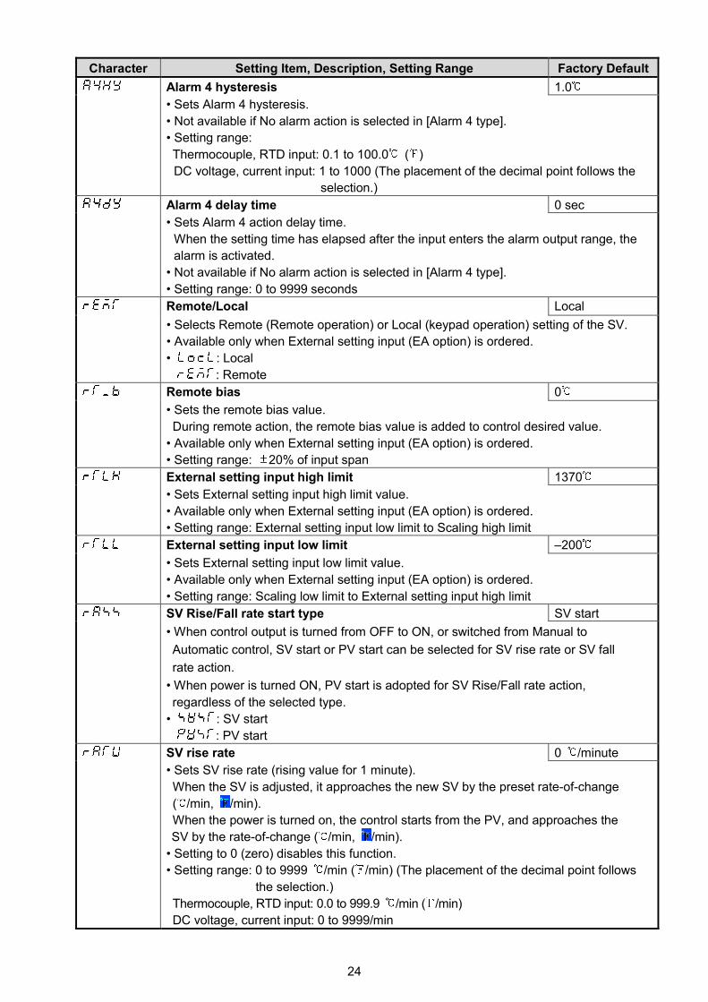
Alarm 4 hysteresis 1.0
• Sets Alarm 4 hysteresis.
• Not available if No alarm action is selected in [Alarm 4 type].
• Setting range:
Thermocouple, RTD input: 0.1 to 100.0 ( )
DC voltage, current input: 1 to 1000 (The placement of the decimal point follows the
selection.)
Alarm 4 delay time 0 sec
• Sets Alarm 4 action delay time.
When the setting time has elapsed after the input enters the alarm output range, the
alarm is activated.
• Not available if No alarm action is selected in [Alarm 4 type].
• Setting range: 0 to 9999 seconds
Remote/Local Local
• Selects Remote (Remote operation) or Local (keypad operation) setting of the SV.
• Available only when External setting input (EA option) is ordered.
• : Local
: Remote
Remote bias 0
• Sets the remote bias value.
During remote action, the remote bias value is added to control desired value.
• Available only when External setting input (EA option) is ordered.
• Setting range: 20% of input span
External setting input high limit 1370
• Sets External setting input high limit value.
• Available only when External setting input (EA option) is ordered.
• Setting range: External setting input low limit to Scaling high limit
External setting input low limit –200
• Sets External setting input low limit value.
• Available only when External setting input (EA option) is ordered.
• Setting range: Scaling low limit to External setting input high limit
SV Rise/Fall rate start type SV start
• When control output is turned from OFF to ON, or switched from Manual to
Automatic control, SV start or PV start can be selected for SV rise rate or SV fall
rate action.
• When power is turned ON, PV start is adopted for SV Rise/Fall rate action,
regardless of the selected type.
• : SV start
: PV start
SV rise rate 0 /minute
• Sets SV rise rate (rising value for 1 minute).
When the SV is adjusted, it approaches the new SV by the preset rate-of-change
( /min, /min).
When the power is turned on, the control starts from the PV, and approaches the
SV by the rate-of-change ( /min, /min).
• Setting to 0 (zero) disables this function.
• Setting range: 0 to 9999 /min ( /min) (The placement of the decimal point follows
the selection.)
Thermocouple, RTD input: 0.0 to 999.9 /min ( /min)
DC voltage, current input: 0 to 9999/min
25
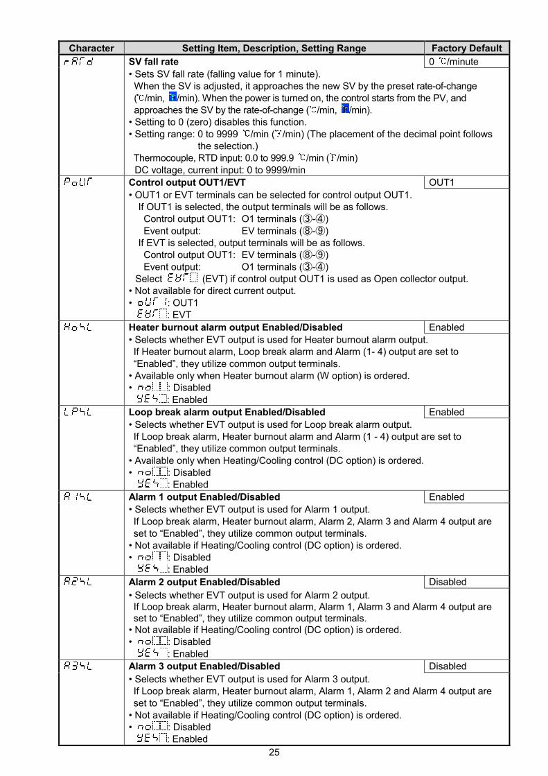
Character Setting Item, Description, Setting Range Factory Default
SV fall rate 0 /minute
• Sets SV fall rate (falling value for 1 minute).When the SV is adjusted, it approaches the new SV by the preset rate-of-change( /min, /min). When the power is turned on, the control starts from the PV, andapproaches the SV by the rate-of-change ( /min, /min).
• Setting to 0 (zero) disables this function.• Setting range: 0 to 9999 /min ( /min) (The placement of the decimal point follows
the selection.)Thermocouple, RTD input: 0.0 to 999.9 /min ( /min)DC voltage, current input: 0 to 9999/min
Control output OUT1/EVT OUT1
• OUT1 or EVT terminals can be selected for control output OUT1.If OUT1 is selected, the output terminals will be as follows.Control output OUT1: O1 terminals (③-④)Event output: EV terminals (⑧-⑨)
If EVT is selected, output terminals will be as follows.Control output OUT1: EV terminals (⑧-⑨)Event output: O1 terminals (③-④)
Select (EVT) if control output OUT1 is used as Open collector output.• Not available for direct current output.• : OUT1
: EVT
Heater burnout alarm output Enabled/Disabled Enabled
• Selects whether EVT output is used for Heater burnout alarm output.If Heater burnout alarm, Loop break alarm and Alarm (1- 4) output are set to“Enabled”, they utilize common output terminals.
• Available only when Heater burnout alarm (W option) is ordered.• : Disabled
: Enabled
Loop break alarm output Enabled/Disabled Enabled
• Selects whether EVT output is used for Loop break alarm output.If Loop break alarm, Heater burnout alarm and Alarm (1 - 4) output are set to“Enabled”, they utilize common output terminals.
• Available only when Heating/Cooling control (DC option) is ordered.• : Disabled
: Enabled
Alarm 1 output Enabled/Disabled Enabled
• Selects whether EVT output is used for Alarm 1 output.If Loop break alarm, Heater burnout alarm, Alarm 2, Alarm 3 and Alarm 4 output areset to “Enabled”, they utilize common output terminals.
• Not available if Heating/Cooling control (DC option) is ordered.• : Disabled
: Enabled
Alarm 2 output Enabled/Disabled Disabled
• Selects whether EVT output is used for Alarm 2 output.If Loop break alarm, Heater burnout alarm, Alarm 1, Alarm 3 and Alarm 4 output areset to “Enabled”, they utilize common output terminals.
• Not available if Heating/Cooling control (DC option) is ordered.• : Disabled
: Enabled
Alarm 3 output Enabled/Disabled Disabled
• Selects whether EVT output is used for Alarm 3 output.If Loop break alarm, Heater burnout alarm, Alarm 1, Alarm 2 and Alarm 4 output areset to “Enabled”, they utilize common output terminals.
• Not available if Heating/Cooling control (DC option) is ordered.• : Disabled
: Enabled
26
Character Setting Item, Description, Setting Range Factory Default
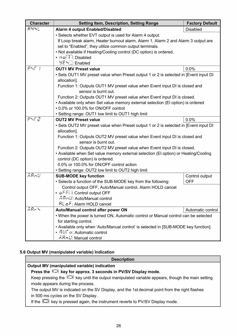
Alarm 4 output Enabled/Disabled Disabled
• Selects whether EVT output is used for Alarm 4 output.
If Loop break alarm, Heater burnout alarm, Alarm 1, Alarm 2 and Alarm 3 output are
set to “Enabled”, they utilize common output terminals.
• Not available if Heating/Cooling control (DC option) is ordered.
• : Disabled
: Enabled
OUT1 MV Preset value 0.0%
• Sets OUT1 MV preset value when Preset output 1 or 2 is selected in [Event input DI
allocation].
Function 1: Outputs OUT1 MV preset value when Event input DI is closed and
sensor is burnt out.
Function 2: Outputs OUT1 MV preset value when Event input DI is closed.
• Available only when Set value memory external selection (EI option) is ordered
• 0.0% or 100.0% for ON/OFF control
• Setting range: OUT1 low limit to OUT1 high limit
OUT2 MV Preset value 0.0%
• Sets OUT2 MV preset value when Preset output 1 or 2 is selected in [Event input DI
allocation].
Function 1: Outputs OUT2 MV preset value when Event input DI is closed and
sensor is burnt out.
Function 2: Outputs OUT2 MV preset value when Event input DI is closed.
• Available when Set value memory external selection (EI option) or Heating/Cooling
control (DC option) is ordered.
0.0% or 100.0% for ON/OFF control action
• Setting range: OUT2 low limit to OUT2 high limit
SUB-MODE key function
• Selects a function of the SUB-MODE key from the following:
Control output
OFF
Control output OFF, Auto/Manual control, Alarm HOLD cancel
• : Control output OFF
: Auto/Manual control
: Alarm HOLD cancel
Auto/Manual control after power ON Automatic control
• When the power is turned ON, Automatic control or Manual control can be selected
for starting control.
• Available only when ‘Auto/Manual control’ is selected in [SUB-MODE key function].
• : Automatic control
: Manual control
5.6 Output MV (manipulated variable) Indication
Description
Output MV (manipulated variable) indication
Press the key for approx. 3 seconds in PV/SV Display mode.
Keep pressing the key until the output manipulated variable appears, though the main setting
mode appears during the process.
The output MV is indicated on the SV Display, and the 1st decimal point from the right flashes
in 500 ms cycles on the SV Display.
If the key is pressed again, the instrument reverts to PV/SV Display mode.

27
6. Simplified Converter Function
Caution• The converter function is selectable only for the Direct current output type.
• When using this controller as a converter, take 1 second into consideration since input/output
response time is approx. 1 second.
• When switching from converter to controller function, the control parameters and values set
by converter function are retained even if the function is switched to controller function.
So, after switching to the controller function, correct the converter parameters to the
controller parameters.
The converter function of this instrument converts each input (thermocouple, RTD, DC voltage and direct
current input) value to “4 to 20 mA DC”, using the control parameters of the controller, and outputs it.
When this instrument is used as a converter, follow steps (1) to (7) described below.
After steps (1) to (7) are finished, this instrument can be used as a converter.
(1) Wire this unit (Power supply, Input and Output).
(2) Turn the power supply of this unit ON.
(3) Enter ‘Auxiliary function setting mode 2’ by pressing the and key (for approx. 3 sec).
(4) Select a sensor type in [Input type] ( ).
(5) Set the high limit of the value to be converted in [Scaling high limit] ( )”.
(6) Set the low limit of the value to be converted in [Scaling low limit] ( )”.
(7) Select Converter ( ) in [Controller/Converter] ( )”.
• To activate the alarm action by Converter function, set the alarm type to Process alarm.
If ‘Converter’ is selected in [Controller/Converter] in Auxiliary function setting mode 2,
parameters below are automatically set. (Table 6-1)
(Table 6-1)
Setting Item Setting Value
SV1 Scaling low limit
SV2 Scaling low limit
Integral time 0
Derivative time 0
OUT1 proportional band 100.0%
OUT2 proportional band 1.0
Manual reset 0.0
Alarm 1 value 0 Enabled/Disabled Disabled
Alarm 1 value 0
Alarm 1 high limit alarm value 0
Alarm 2 value 0 Enabled/Disabled Disabled
Alarm 2 value 0
Alarm 2 high limit alarm value 0
Alarm 3 value 0 Enabled/Disabled Disabled
Alarm 3 value 0
Alarm 3 high limit alarm value 0
Alarm 4 value 0 Enabled/Disabled Disabled
Alarm 4 value 0
Alarm 4 high limit alarm value 0
Loop break alarm time 0
Loop break alarm span 0
Direct/Reverse action Direct action
Event input DI allocation 000

28
Setting Item Setting Value
Remote/Local (EI option) Local
SV rise rate 0
SV fall rate 0
OUT1 high limit 100
OUT1 low limit 0
Alarm 1 to Alarm 4 types No alarm action
Alarm 1 hysteresis 1.0
Alarm 1 delay time 0
Alarm 1 Energized/De-energized Energized
Alarm 2 hysteresis 1.0
Alarm 2 delay time 0
Alarm 2 Energized/De-energized Energized
Alarm 3 hysteresis 1.0
Alarm 3 delay time 0
Alarm 3 Energized/De-energized Energized
Alarm 4 hysteresis 1.0
Alarm 4 delay time 0
Alarm 4 Energized/De-energized Energized
6.1 Fine Adjustment of Converter Output (4 to 20 mA DC)
Outputs “4 to 20 mA DC” corresponding to the input from scaling low limit to high limit value.
Fine adjustment rate is 1/1000 of the scaling span.
Fine adjustment method
Be sure to adjust the zero side first. Then adjust the span side.
Adjust zero at “Manual reset ( )”, and adjust span at “Proportional band ( )”.
(1) Zero adjustment1 Enter the value so that the PV Display can indicate the same value as the scaling low limit value.2 Press the and key (in that order). The unit proceeds to Sub setting mode.3 Press the key several times until “Manual reset ( )” appears.4 Adjust the converter output value so that it can become 4 mA DC by increasing and decreasing
the value with and keys.
Pressing the key decreases the value, and the key increases it.5 Revert to the PV/SV Display mode by pressing the key several times.
(2) Span adjustment1 Enter the value so that the PV Display can indicate the same value as the scaling high limit value.2 Press the and key (in that order). The unit proceeds to Sub setting mode.3 Proceed to the “Proportional band ( )” by pressing the key.4 Adjust the converter output value so that it can become 20 mA DC by increasing and decreasing
the value with the and keys.
Pressing the key decreases the value, and the key increases it.5 Revert to the PV/SV Display mode by pressing the key several times.
(3) Repeat steps (1) and (2) several times.

29
6.2 Converter Setting Example
[Other Inputs except 4 to 20 mA DC]
Input, output conditions
Input: 6 to 14 mA DC (Indication: 30.0 to 130.0)
Output: 4 to 20 mA DC
Setting method
(1) Calculating Scaling high and low limit value of 4 to 20 mA DC
Indication value per mA DC: (130.0 – 30.0) ÷ (14 – 6) = 100 ÷ 8 = 12.5
Scaling high limit value: 130.0 + (20 – 14) x 12.5 = 205.0
Scaling low limit value: 30.0 – (6 – 4) x 12.5 = 5.0
(2) Calculating OUT proportional band of 6 to 14 mA DC
OUT proportional band (P) = {(14 – 6) ÷ (20 – 4)} x 100 = 0.5 x 100 = 50 (%)
(3) Calculating SV so that output can become 4 mA DC from 6 mA DC input (Parallel shift
setting)
SV = {(6 – 4) x 12.5} + 5.0 (Scaling low limit) = 30.0
Input, output and indication
(Fig. 6.2-1)
P = 50%
Output
20 mA
4 mA
4 mA 6 mA 20 mA14 mAInput
Indication 5.0 30.0 205.0130.0
SV
P = 50%
12 mA
105.0
(2)
(3)
: Input and output when P=100%, SV=5.0
: Input and output when P=50%, SV=5.0
: Input and output when P=50%, SV=30.0

30
7. OperationAfter the unit is mounted within the control panel (DIN rail) and wiring is completed, operate the unit
following the procedure below.
(1) Turn the power supply to the DCL-33A ON.
For approx. 3 seconds after power is turned on, sensor input characters and temperature unit are
indicated on the PV Display, and the input range high limit value is indicated on the SV Display.
See (Table 5-1) on p.11. During this time, all outputs and LED indicators are in OFF status.
(If any other value is set in [Scaling high limit], the SV Display indicates it.)
After that, the PV Display indicates PV (process variable), and the SV Display indicates SV (desired
value).
(2) Enter each set value.
Enter each set value, referring to “5. Setup”.
(3) Turn the load circuit power ON.
Control action starts so as to keep the control target at the SV (desired value).
SUB-MODE Key Function
The SUB-MODE key function differs depending on the selection in [SUB-MODE key function].
• If ‘Control output OFF’ is selected:
The control action and output of an instrument (or instruments) can be turned OFF without turning
OFF their power supplies using this function.
If the control output OFF function is enabled, and the PV Display will indicate , turning all
outputs OFF.
To enable the control output OFF function, press the SUB-MODE key for approximately 1 second in
PV/SV Display mode.
To enable the control output OFF function, press the SUB-MODE key for approximately 3 seconds
in setting mode.
If the SUB-MODE key is pressed for approximately 1 second again, the function will be cancelled,
and the unit will return to PV/SV Display mode.
• If ‘Auto/Manual control’ is selected:
Auto/Manual control can be switched.
Each time the SUB-MODE key is pressed for approximately 1 second in PV/SV Display mode,
Automatic or Manual control can be switched.
• If ‘Alarm HOLD cancel’ is selected:
Alarm Hold can be cancelled for the Alarm with Hold function.
To enable the Alarm HOLD cancel function, press the SUB-MODE key for approximately 1 second
in PV/SV Display mode.
To enable the Alarm HOLD cancel function, press the SUB-MODE key for approximately 3 seconds
in setting mode.
Event Input
Event Input DI action has priority over key operation.
Set value memory external selection (EI option)
By closing or opening the Event Input DI contact, SV1 and SV2 can be selected.
Depending on the selection in [Event input DI allocation], the following differences result in:
If 001 (Set value memory) is selected in [Event input DI allocation]:
Event input DI Open: SV1
Event input DI Closed: SV2
If 008 (Set value memory) is selected in [Event input DI allocation]:
Event input DI Open: SV2
Event input DI Closed: SV1

31
8. Action Explanations8.1 OUT1 Action
8.2 OUT1 ON/OFF Control Action
: Turns ON or OFF.
Heating (Reverse) action Cooling (Direct) action
Controlaction
Relay contact
output
Non-contact
voltage output
Direct currentoutput
Indicator(OUT) Green
Lit Unlit
0 V DC
+0 V DC
+12 V DC
+12 V DC
+
20 mA DC
+4 mA DC
+4 mA DC
+20 mA DC
+
ON
OFF
ON
OFF
Hysteresis
Unlit Lit
Hysteresis
SV SV
4
3
4
3
4
3
4
3
4
3
4
3
4
3
4
3
4
3
4
3
4
3
4
3
: Turns ON or OFF.
Heating (Reverse) action Cooling (Direct) action
Control
action
Cycle action is performedaccording to deviation
Relay contactoutput
Non- contactvoltageoutput
Changes continuouslyaccording to deviation
Direct current
output
Indicator
(OUT) GreenLit Unlit
ON
OFF
SV
Proportional band
ON
OFF
0 V DC 0/12 V DC12 V DC
+
20 mA DC 20 to 4 mA DC 4 to 20 mA DC
Proportional band
Lit
0 V DC 12 V DC12/0 V DC
20 mA DC4 mA DC
+ + + + +
++++++
Unlit
4 mA DC
4
3
4
3
4
3
4
3
4
3
4
3
4
3
4
3
4
3
4
3
4
3
4
3
4
3
4
3
4
3
4
3
4
3
4
3
SV
Cycle action is performedaccording to deviation
Cycle action is performedaccording to deviation
Cycle action is performedaccording to deviation
Changes continuouslyaccording to deviation

32
OFF
ON
SV SV
OFF
ON
OFF
ON
OFF
ON
OFF
ON
SV
SV
OFF
ON
High limit alarm Low limit alarm
High/Low limit range alarm High/Low limit range independent alarm
High/Low limits alarm High/Low limits independent alarm
Alarmaction
Alarmoutput
Alarmaction
Alarmoutput
Alarmaction
Alarmoutput
EV1 value SV
+side
- side
+side
- side
SV
EV1 value
EV1value EV1value
EV1 hysteresisEV1 hysteresis
EV1 hysteresis EV1 hysteresis
-EV1 value +EV1 value -EV1 value +EV1 value
EV1 hysteresis EV1 hysteresis
EV1 low limit value EV1 high limit value
EV1 high limit valueEV1low limit value
8.3 Heater Burnout Alarm Action
: Event output EV terminals 8 and 9 are ON.
: Event output EV terminals 8 and 9 are OFF.
The Event output EVT indicator lights up when Event output EV terminals 8 and 9 are ON,and turns off when they are OFF.
8.4 Alarm Action
Heater burnoutalarm action
ON
OFF
Heater burnout alarm value
Load current LargeSmall
Indicator
UnlitLit(EVT) Red

33
OFF
ON
OFF
ON
Process high alarm Process low alarm
Alarmaction
Alarmoutput
EV1 hysteresis
EV1 value EV1 value
EV1 hysteresis
High limit with standby alarm
OFF
ON
SV SV
OFF
ON
OFF
ON
OFF
ON
SV
Low limit with standby alarm
High/Low limits with standby alarm H/L limits with standby independent alarm
Alarmaction
Alarmoutput
Alarmaction
Alarmoutput
SV
+ side
- side
+side
- side
-EV1 value -EV1 value+EV1 value +EV1 value
EV1 hysteresis
EV1 hysteresis EV1 hysteresis
EV1 hysteresis
EV1 value EV1 value EV1 low limit value EV1 high limit value
The Event output EVT indicator lights up when Event output EV terminals 8 and 9 are ON,
and turns off when they are OFF.
: Event output EV terminals 8 and 9 are ON.
: Event output EV terminals 8 and 9 are ON or OFF.
: Event output EV terminals 8 and 9 are OFF.
: Alarm output is in Standby.

34
8.5 OUT2 (Heating/Cooling Control) Action
Cycle action is performedaccording to deviation.
OFF
ON
OUT1 P-band
SV
3+
4-
12 V DC
3+
4-
12/0 V DC
3+
4-
0 V DC
3+
4-
20 mA DC
3+
4-
20 to 4 mA DC
3+
4-
4 mA DC
3
4
3
4
3
4
8+
9-
OFF/ON
8+
9-
OFF
8+
9-
ON
OFF
ON
: Turns ON (lit) or OFF (unlit).
Lit
OUT2 P-band
Heatingaction
Coolingaction
Controlaction
Cycle action is performedaccording to deviation.
Changes continuouslyaccording to deviation.
Indicator(OUT)Green
Indicator(EVT)Red Unlit
Unlit
Lit
: Represents Heating control action.
: Represents Cooling control action.
Directcurrentoutput
Opencollectoroutput
Relaycontactoutput
Non-contactvoltageoutput
Cycle action is performedaccording to deviation.

35
8.6 OUT2 Action (When Setting Overlap Band)
OFF
ON
SV
OFF
ON
Heatingcontrol
Relaycontactoutput
Cycle action is performedaccording to deviation.
3+
4-
12 V DC
3+
4-
12/0 V DC
3+
4-
0 V DC
3+
4-
20 mA DC
3+
4-
20 to 4 mA DC
3+
4-
4 mA DC
3
4
3
4
3
4
8+
9-
OFF/ON
8+
9-
OFF
8+
9-
ON
OUT1 P-band
OUT2 P-band
Overlapband
Coolingcontrol
Controlaction
Cycle action is performedaccording to deviation.
Changes continuouslyaccording to deviation.
Cycle action is performedaccording to deviation.
Indicator(OUT)Green
Indicator(EVT)Red
Lit
Unlit
Unlit
Lit
: Turns ON (lit) or OFF (unlit).
: Represents Heating control action.
: Represents Cooling control action.
Non-contactvoltageoutput
Directcurrentoutput
Opencollectoroutput

36
OUT1 P-band Dead band (OUT2 P-band)
Controlaction
Heatingaction
Relaycontactoutput
Changes continuouslyaccording to deviation.
Unlit
Indicator (OUT)
Lit
OFF
ON
SV
OFF
ON
3+
4-
12 V DC
3+
4-
12/0 V DC
3+
4-
0 V DC
3+
4-
20 mA DC
3+
4-
20 to 4 mA DC
3+
4-
4 mA DC
444
333
9 9 9
8 8 8
Indicator (EVT)
Cycle action is performedaccording to deviation.
Lit
UnlitGreen
Red
+
-
+
-
+
-OFF/ON ONOFF
Coolingaction
Cycle action is performedaccording to deviation.
Cycle action is performedaccording to deviation.
Non-contactvoltageoutput
Directcurrentoutput
Open collectoroutput
8.7 OUT2 Action (When Setting Dead Band)

37
9. AT (Auto-tuning)In order to decide each value of P, I, D and ARW automatically, the auto-tuning process should be
made to fluctuate to obtain an optimal value.
One of 3 types of fluctuation below is automatically selected.
For DC input, the AT process will fluctuate around the SV for conditions of (A), (B) and (C).
Sometimes the auto-tuning process will not fluctuate if auto-tuning is performed at or near room
temperature. Therefore auto-tuning might not finish normally.
(A) In the case of a large difference between the SV and processing temperature as the
temperature is rising
When AT bias is set to 20 , the AT process will fluctuate at temperatures 20 lower than the SV.
Temperature 20 lower than the SV
(1) Calculates PID constant
(2) PID constant calculated
(3) Controlled by the PID
constant set by auto-tuning
(4) AT bias value
(B) When control is stable
The AT process will fluctuate around the SV.
(1) Calculates PID constant
(2) PID constant calculated
(3) Controlled by the PID
constant set by auto-tuning
(C) In the case of a large difference between the SV and processing temperature as the
temperature is falling
When AT bias is set to 20 , the AT process will fluctuate at temperatures 20 higher than the SV.
Temperature 20 higher than the SV
(1) Calculates PID constant
(2) PID constant calculated
(3) Controlled by the PID
constant set by auto-tuning
(4) AT bias value
(1) (2) (3)
(4)
AT starting point
SV
Temperature
Time
AT starting point
(1) (2) (3)
Temperature
SV
Time
AT starting point
(1) (2) (3)
(4)
Temperature
SV
Time

38
10. Specifications10.1 Standard Specifications
Model: DIN rail mounted indicating controllerMounting: DIN railSetting: Input system using membrane sheet keyDisplay:
PV Display: Red LED 4 digits, character size 7.4 x 4.0 mm (H x W)SV Display: Green LED 4 digits, character size 7.4 x 4.0 mm (H x W)
Input:Thermocouple: K, J, R, S, B, E, T, N, PL- , C (W/Re5-26) External resistance: 100 max.
However, for thermocouple B, external resistance: 40 max.RTD: Pt100, JPt100, 3-wire type
Allowable input lead wire resistance (10 max. per wire)Direct current: 0 to 20 mA DC, 4 to 20 mA DC, input impedance 50
If direct current input (Externally mounted 50 shunt resistor) is designated,connect a 50 shunt resistor (sold separately) between input terminals.Allowable input current: 50 mA max.
DC voltage:
0 to 1 V DC 0 to 5 V DC, 1 to 5 V DC, 0 to 10 V DC
Input impedance 1 M min. 100 k min.
Allowable input voltage 5 V max. 15 V max.Allowable signal sourceresistance
2 k max. 100 max.
Indication performance:
Base accuracy (at ambient temperature 23 , for a single unit mounting):Thermocouple: Within 0.2% of input span 1 digit, or within 2 (4 ), whichever is greater
R, S inputs, 0 to 200 (32 to 392 ): Within 6 (12 )B input, 0 to 300 (32 to 572 ): Accuracy is not guaranteed.K, J, E, T, N input, less than 0 (32 ):
Within 0.4% of input span 1 digit, or 4 (8 ), whichever is greaterRTD: Within 0.1% of input span 1 digit, or within 1 (2 ), whichever is greaterDC voltage: Within 0.2% of input span 1 digitDirect current: Within 0.2% of input span 1 digit
Input sampling period: 125 msControl performance: Same as setting accuracy and base accuracy
Control action:• PID control [with auto-tuning (AT) function]• PI control: When derivative time is set to 0• PD control (with manual reset function): When integral time is set to 0• P control (with manual reset function): When derivative and integral time are set to 0• ON/OFF control: When OUT1 proportional band is set to 0.0
OUT1 proportional band: 0.0 to 110.0% (ON/OFF control when set to 0.0)Integral time: 0 to 3600 seconds (Disabled when set to 0)Derivative time: 0 to 1800 seconds (Disabled when set to 0)OUT1 proportional cycle: 1 to 120 secondsARW: 0 to 100%Manual reset: Proportional band converted valueOUT1 high, OUT1 low limit: 0 to 100% (Direct current output type: –5 to 105%)
(Not available for ON/OFF control)OUT1 ON/OFF hysteresis: Thermocouple, RTD input: 0.1 to 100.0 ( )
DC voltage, current input: 1 to 1000 (The placement of thedecimal point follows the selection.)
Control output (OUT):• Relay contact: 1a, Control capacity: 3 A 250 V AC (Resistive load)
1 A 250 V AC (Inductive load cos = 0.4)Electrical life: 100,000 cycles
• Non-contact voltage (for SSR drive): 12 V DC 15% Max. 40 mA DC (Short circuit protected)• Direct current: 4 to 20 mA DC, Load resistance: Max. 550
Output accuracy: Within 0.3% of the output spanResolution: 12000

39
EVT output:
• Alarm output
[Alarm, Loop break alarm and Heater burnout alarm (W option) utilize common outputterminals.]
The alarm action point is set by deviation from the SV (excluding Process alarm), and when
input goes outside the range, alarm output is turned ON or OFF (High/Low limit range alarm).
When De-energized is selected in [Alarm Energized/De-energized], alarm output is activated
conversely.
Setting accuracy: Same as base accuracy
Action: ON/OFF action
Hysteresis: Thermocouple, RTD input: 0.1 to 100.0 ( )
DC voltage, current input: 1 to 1000 (The placement of the decimal point
follows the selection.)
Output: Open collector, Control capacity: 0.1 A 24 V DC
Alarm type: One alarm action can be selected from below by front keypad operation:
High limit, Low limit, High/Low limits, High/Low limits independent alarm,
High/Low limit range, High/Low limit range independent alarm, Process
high, Process low, High limit with standby, Low limit with standby,
High/Low limits with standby, High/Low limits with standby independent
alarm, and No alarm action
The above 12 alarm types and No alarm action can be selected.
Energized/De-energized: Alarm (EVT) output Energized/De-energized can be selected.
Energized De-energized
EVT indicator (Red) Lights up Lights up
EVT output ON OFF
Alarm HOLD function: Once the alarm is activated, alarm output is maintained
until the power is turned off.
• Loop break alarm output
[Loop break alarm, Alarm and Heater burnout alarm (W option) utilize common output
terminals.]
Detects heater burnout, sensor burnout and actuator trouble.
Setting range: Loop break alarm time: 0 to 200 minutes
Loop break alarm span:
Thermocouple, RTD input: 0 to 150 ( ) or 0.0 to 150.0 ( )
DC voltage, current input: 0 to 1500 (The placement of the decimal
point follows the selection.)
Output: Open collector, Control capacity: 0.1 A 24 V DC
Converter function: See “6. Simplified Converter Function”.
Attached function:
[Set value lock]
[Sensor correction]
[Power failure countermeasure]
The setting data is backed up in non-volatile IC memory.
[Self diagnosis]
The CPU is monitored by a watchdog timer, and if an abnormal status occurs, the controller
is switched to warm-up status, turning all outputs off.
[Automatic cold junction temperature compensation] (Only thermocouple input)
Detects the temperature at the connection terminal (between the thermocouple and the
instrument), and maintains it at the same status as if the reference junction location
temperature were at 0 (32 ).
[Burnout]
When the thermocouple or RTD input is burnt out, OUT is turned OFF (for direct current
output, OUT low limit value), and the PV Display flashes “ ”.

40
[Input error indication]
Output
status
when input
errors occur
(*1)
Contents
and
Indication
Output status
Controller/Converter
Controller Converter
OUT1 OUT2 OUT1
Direct action Reverse action Direct Reverse Direct Reverse
“ ”flashes.
ON (20 mA)
or OUT1 high
limit value (*2)
OFF (4 mA)
or
OUT1 low limitvalue
OUT2low limit value
20 mAorOUT1highlimit value
4 mAorOUT1lowlimit value
OFF (4 mA)
or OUT1 low
limit value
“ ”flashes.
OFF (4 mA)
or
OUT1 low
limit value
ON (20 mA)
or
OUT1 high limit
value (*2)OUT2low limit value
4 mAorOUT1lowlimit value
20 mAorOUT1highlimit value
OFF(4 mA) or
OUT1 low limit
value
(*1) [Output status when input errors occur] can be used only for controllers using direct current
and voltage inputs, and direct current output. If OUT is not Direct current output, the output
status will be the same as when is selected in [Output status when input errors
occur]. For manual control, the preset MV is output.
(*2) Outputs a value between OFF (4 mA) and ON (20 mA) or between OUT1 low limit value
and OUT1 high limit value, depending on deviation.
Thermocouple, RTD input
Input Input range Indication range Control range
K,T–199.9 to 400.0 –199.9 to 450.0 –205.0 to 450.0
–199.9 to 750.0 –199.9 to 850.0 –209.0 to 850.0
Pt100
–199.9 to 850.0 –199.9 to 900.0 –210.0 to 900.0
–200 to 850 –210 to 900 –210 to 900
–199.9 to 999.9 –199.9 to 999.9 –211.0 to 1099.9
–300 to 1500 –318 to 1600 –318 to 1600
JPt100
–199.9 to 500.0 –199.9 to 550.0 –206.0 to 550.0
–200 to 500 –207 to 550 –207 to 550
–199.9 to 900.0 –199.9 to 999.9 –211.0 to 999.9
–300 to 900 –312 to 1000 –312 to 1000
Indication range and Control range for thermocouple inputs except above:
[Input range low limit value – 50 (100 )] to [Input range high limit value + 50 (100 )]
DC input
Indication range: [Scaling low limit value – Scaling span x 1%] to [Scaling high limit value
+ Scaling span x 10%]
However, if the input value is out of the range –1999 to 9999, the PV
Display flashes “ ” or “ ”.
Control range: [Scaling low limit value – Scaling span x 1%] to [Scaling high limit value
+ Scaling span x 10%]
DC input disconnection
When DC input is burnt out, the PV Display flashes “ ” for 1 to 5 V DC and 4 to 20 mA
DC inputs, and “ ” for 0 to 1 V DC input.
For 0 to 5 V DC, 0 to 10 V DC and 0 to 20 mA DC inputs, the PV Display indicates the
value corresponding with 0 V or 0 mA input.

41
Insulation/Dielectric strength: Circuit insulation configuration
Insulation resistance: 10 M minimum, at 500 V DC
Dielectric strength: 1.5 kV AC for 1 minute
Power supply: 100 to 240 V AC 50/60 Hz, 24 V AC/DC 50/60 Hz
Allowable voltage fluctuation range: 100 to 240 V AC: 85 to 264 V AC, 24 V AC/DC: 20 to 28 V AC
Power consumption: 100 to 240 V AC: Approx. 5 VA max.
24 V AC: Approx. 4 VA max.
24 V DC: Approx. 4 W max.
Ambient temperature: 0 to 50 (32 to 122 )
Ambient humidity: 35 to 85%RH (non-condensing)
Weight: Approx.100 g
External dimension: 22.5 x 75 x 100 mm (W x H x D)
Material: Flame-resistant resin (Case)
Color: Light gray (Case)
Accessories included:
Instruction manual excerpt: 1 copy
When Heater burnout alarm output (W option) is ordered: Connector harness W 3 m: 1 length
When Heater burnout alarm output (W option) is ordered:
For rated current 5A, 10A, 20A: CT (CTL-6-S-H): 1 piece
For rated current 50A: CT (CTL-12-S36-10L1U): 1 piece
When Set value memory external selection (EI option) is ordered:
Connector harness AOJ 3 m: 1 length
When External setting input (EA option) is ordered: Connector harness AOJ 3 m: 1 length
Accessories sold separately: 50 shunt resistor for direct current input
10.2 Optional Specifications
Heater burnout alarm output (W option)
Watches the heater current with CT (Current transformer), and detects the burnout.
This alarm is also activated when sensor is burnt out, or when indication is overscale or underscale.
Heater burnout alarm, Alarm and Loop break alarm utilize common output terminals.
This option cannot be used for direct current output type.
Rating: 5 A [W (5 A)], 10 A [W (10 A)], 20 A [W (20 A)], 50 A [W (50 A)] (Must be specified)
Setting range: 5 A [W (5 A)]: 0.0 to 5.0 A (OFF when set to 0.0)
10 A [W (10 A)]: 0.0 to 10.0 A (OFF when set to 0.0)
20 A [W (20 A)]: 0.0 to 20.0 A (OFF when set to 0.0)
50 A [W (50 A)]: 0.0 to 50.0 A (OFF when set to 0.0)
Setting accuracy: 5% of the heater rated current
Action point: Setting value
Action: ON/OFF action
Output: Open collector, Control capacity: 0.1 A 24 V DC
EVTInput
Electrically insulated
OUTPower supply
CPU
CT inputor
Set valuememory
Communication
Externalsetting input
1 2 3 4
5 6 7 8 9

42
Serial communication (C5 option)
The following operations are performed from an external computer.
(1) Reading and writing of the SV, PID and other various set values
(2) Reading of the PV and action status
(3) Function change
Cable length : Max. 1.2 km, Cable resistance: Within 50 (Terminators are not necessary, but
if used, use 120 or more on one side.)
Communication line: EIA RS-485
Communication method: Half-duplex communication
Communication speed: 2400/4800/9600/19200/38400 bps (Default: 9600bps)(Selectable by keypad)
Synchronization method: Start-stop synchronization
Data bit/Parity: 7, 8/Even, Odd, No parity (Selectable by keypad)
Stop bit: 1, 2 (Selectable by keypad)
Communication protocol: Shinko protocol/Modbus ASCII/Modbus RTU (Selectable by keypad)
(Default: Shinko protocol)
Data format:
Error correction: Command request repeat system
Error detection: Parity check, checksum (Shinko protocol), LRC (Modbus ASCII), CRC-16 (Modbus RTU)
Digital external setting:
SV of the programmable controller (with the SVTC option) can be digitally transmitted to the
DCL-33A (with the C5 option) by combining the programmable controller with the DCL-33A. When
data from the programmable controller is larger than SV high limit or smaller than SV low limit,
DCL-33A ignores the value and controls with the previous value. The control desired value adds SVTC
bias value to the value received by the SVTC command.
Heating/Cooling control output (DC option)
OUT2 proportional band: 0.0 to 10.0 times OUT1 proportional band (ON/OFF control when set to 0.0)
Integral time: Same as that of OUT1
Derivative time: Same as that of OUT1
OUT2 proportional cycle: 1 to 120 seconds
Overlap/Dead band: Thermocouple, RTD input: –100.0 to 100.0 ( )
DC voltage, current input: –1000 to 1000 (The placement of the decimal point
follows the selection)
OUT2 ON/OFF hysteresis: Thermocouple, RTD input: 0.1 to 100.0 ( )
DC voltage, current input: 1 to 1000 (The placement of the decimal point
follows the selection.)
OUT2 high limit, OUT2 low limit: 0 to 100%
OUT2 cooling mode: Air cooling (Linear characteristics), Oil cooling (1.5th power of the linear
characteristics), Water cooling (2nd power of the linear characteristics)
Output: Open collector, control capacity: 0.1 A 24 V DC
Communication protocol Shinko protocol Modbus ASCII Modbus RTU
Start bit 1 1 1
Data bit 7 7 8
Parity Even Even (Odd, No parity) No parity (Even, Odd)
Stop bit 1 1 or 2 1 or 2

43
Set value memory external selection (EI option)
Switches SV1 and SV2 by external contact.
If 001 is selected in [Event input DI allocation]:
DI input Open: SV1
DI input Closed: SV2
If 008 is selected in [Event input DI allocation]:
DI input Open: SV2
DI input Closed: SV1
Circuit current when closed: Approx. 2 mA
External setting input (EA option)
If ‘Remote’ is selected in [Remote/Local], external analog signal will become SV.
Remote bias value is added to the control desired value.
Setting signal: Direct current 4 to 20 mA
Allowable input: 50 mA DC max.
Input impedance: 50 max.
Input sampling period: 125 msec
Option combination ( : Can be used together.)
Option Code W DC C5 EA EI
W - -DCC5EA - -EI - -
W, EA and EI options cannot be used together.
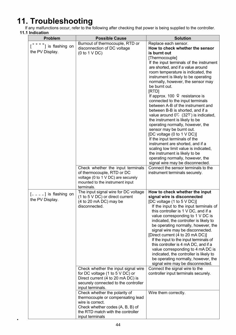
44
11. TroubleshootingIf any malfunctions occur, refer to the following after checking that power is being supplied to the controller.
11.1 Indication
Problem Possible Cause Solution
[ ] is flashing on
the PV Display.
Burnout of thermocouple, RTD ordisconnection of DC voltage(0 to 1 V DC)
Replace each sensor.How to check whether the sensoris burnt out[Thermocouple]If the input terminals of the instrumentare shorted, and if a value aroundroom temperature is indicated, theinstrument is likely to be operatingnormally, however, the sensor maybe burnt out.[RTD]If approx. 100 resistance isconnected to the input terminalsbetween A-B of the instrument andbetween B-B is shorted, and if avalue around 0 (32 ) is indicated,the instrument is likely to beoperating normally, however, thesensor may be burnt out.[DC voltage (0 to 1 V DC)]If the input terminals of theinstrument are shorted, and if ascaling low limit value is indicated,the instrument is likely to beoperating normally, however, thesignal wire may be disconnected.
Check whether the input terminalsof thermocouple, RTD or DCvoltage (0 to 1 V DC) are securelymounted to the instrument inputterminals.
Connect the sensor terminals to theinstrument terminals securely.
[ ] is flashing on
the PV Display.
The input signal wire for DC voltage(1 to 5 V DC) or direct current(4 to 20 mA DC) may bedisconnected.
How to check whether the inputsignal wire is disconnected[DC voltage (1 to 5 V DC)]
If the input to the input terminals ofthis controller is 1 V DC, and if avalue corresponding to 1 V DC isindicated, the controller is likely tobe operating normally, however, thesignal wire may be disconnected.
[Direct current (4 to 20 mA DC)]If the input to the input terminals ofthis controller is 4 mA DC, and if avalue corresponding to 4 mA DC isindicated, the controller is likely tobe operating normally, however, thesignal wire may be disconnected.
Check whether the input signal wirefor DC voltage (1 to 5 V DC) orDirect current (4 to 20 mA DC) issecurely connected to the controllerinput terminals.
Connect the signal wire to thecontroller input terminals securely.
Check whether the polarity ofthermocouple or compensating leadwire is correct.Check whether codes (A, B, B) ofthe RTD match with the controllerinput terminals
Wire them correctly.
•

45
Problem Possible Cause Solution
The value set in[Scaling low limit]remains on the PVDisplay.
Check whether the input signal wirefor DC voltage (0 to 5 V DC, 0 to 10V DC) or direct current (0 to 20 mADC) is disconnected.
How to check whether the inputsignal wire is disconnected[DC voltage (0 to 5 V DC, 0 to 10 VDC)]
If the input to the input terminal ofthis controller is 1 V DC, and if avalue (converted value from Scalinghigh, low limit setting) corre-sponding to 1 V DC is indicated, thecontroller is likely to be operatingnormally, however, the signal wiremay be disconnected.
[Direct current (0 to 20 mA DC)]If the input to the input terminal ofthis controller is 4 mA DC, and ifa value (converted value fromScaling high, low limit setting) corre-sponding to 4 mA DC is indicated,the controller is likely to beoperating normally, however, thesignal wire may be disconnected.
Check whether the input signal wirefor DC voltage (0 to 5 V DC, 0 to10V DC) or direct current (0 to 20 mADC) is securely connected to thecontroller input terminals.
Connect the signal wire to the
controller input terminals securely.
The indication of thePV Display is abnormalor unstable.
Check whether the sensor input ortemperature unit ( , ) is correct.
Set the sensor input and thetemperature unit ( , ) correctly.
Sensor correction value is notsuitable.
Set it to a suitable value.
Check whether the sensorspecification is correct.
Set the sensor specification properly.
AC leaks into the sensor circuit. Use an ungrounded type sensor.
There may be equipment thatinterferes with or makes noise nearthe instrument.
Keep the instrument clear of anypotentially disruptive equipment.
[ ] is indicated onthe PV Display.
The internal memory is defective. Please contact our main office ordealers.
11.2 Key Operation
Problem Possible Cause Solution
• Settings (SV, P, I, D,proportional cycle,alarm value, etc.) areimpossible.
• The values do notchange by the or
key.
Set value lock (Lock 1 or Lock 2) is
selected.
Release the lock selection.
Auto-tuning (AT) is performing. Cancel auto-tuning (AT) if required.
The setting indicationdoes not change withinthe rated input rangeeven if the orkey is pressed, and newvalues are unable to beset.
Scaling high limit or low limit (in
Auxiliary function setting mode 2)
may be set at the point where the
value does not change.
Set it to a suitable value while in
Auxiliary function setting mode 2.

46
11.3 Control
Problem Possible Cause Solution
The PV (temperature)
does not rise.
The sensor is out of order. Replace the sensor.
Check whether the sensor is
securely mounted to the instrument
input terminals, or control output
terminals are securely mounted
to the actuator input terminals.
Mount the sensor or control output
terminals securely.
Ensure that wiring of sensor
terminals or control output terminals
is correct.
Wire them correctly.
The control output
remains in an ON
status.
OUT low limit value is set to 100%
or higher in Auxiliary function
setting mode 2.
Set it to a suitable value.
The control output
remains in an OFF
status.
OUT high limit value is set to 0% or
less in Auxiliary function setting
mode 2.
Set it to a suitable value.
For all other malfunctions, please contact our main office or dealers.

47
12. Character Table12.1 Main Setting Mode
Character Setting Item, Description, Setting Range Factory Default
SV1
Scaling low limit to scaling high limit (For DC voltage and current
input, the placement of the decimal point follows the selection.)
0
12.2 Sub Setting Mode
Character Setting Item, Description, Setting Range Factory Default
AT Perform/Cancel
: AT Cancel
: AT Perform
AT Cancel
OUT1 proportional band
0.0 to 110.0%
2.5%
OUT2 proportional band
0.0 to 10.0 times
1.0 times
Integral time
0 to 3600 sec
200 sec
Derivative time
0 to 1800 sec
50 sec
ARW (Anti-reset windup)
0 to 100%
50%
OUT1 proportional cycle
1 to 120 sec
Relay contact output: 30 sec
Non-contact voltage output: 3 sec
OUT2 proportional cycle
1 to 120 sec
3 sec
Manual reset
Proportional band converted value (For DC voltage and currentinput, the placement of the decimal point follows the selection.)
0.0
Alarm 1 value
See (Table 12.2-1)(p.48). (For DC voltage and current input, the
placement of the decimal point follows the selection.)
0
. と
XX.X
alternating
display
Heater burnout alarm value
Rated current 5 A: 0.0 to 5.0 A
Rated current 10 A: 0.0 to 10.0 A
Rated current 20 A: 0.0 to 20.0 A
Rated current 50 A: 0.0 to 50.0 A
0.0 A
Loop break alarm time
0 to 200 minutes
0 minutes
Loop break alarm span
Thermocouple, RTD input: 0 to 150 ( ) or 0.0 to 150.0 ( )
DC voltage, current input: 0 to 1500 (The placement of the decimal
point follows the selection.)
0

48
(Table 12.2-1)
Alarm Type Setting RangeHigh limit alarm –(Scaling span) to scaling span Minimum
negative value:–199.9 or –1999
Maximumpositive value:999.9 or 9999
Low limit alarm –(Scaling span) to scaling span
High/Low limits alarm 0 to scaling spanHigh/Low limit range alarm 0 to scaling spanProcess high alarm Scaling low limit value to scaling high limit valueProcess low alarm Scaling low limit value to scaling high limit valueHigh limit with standby alarm –(Scaling span) to scaling spanLow limit with standby alarm –(Scaling span) to scaling span
High/Low limits with standby alarm 0 to scaling span
High/Low limits independent alarm 0 to scaling span
High/Low limit range independentalarm
0 to scaling span
High/Low limits with standbyindependent alarm
0 to scaling span
12.3 Auxiliary Function Setting Mode 1
Character Setting Item, Setting Range Factory Default
Set value lock Unlock
(Unlock): All set values can be changed.(Lock 1): None of the set values can be changed.(Lock 2): Only main setting mode can be changed.(Lock 3): All set values – except [input type] and [Controller/Converter] – can
be changed. However, changed values revert to their previous values afterpower is turned off because they are not saved in the non-volatile memory.Do not change any setting item in Auxiliary function setting mode 2. If any itemin Auxiliary function setting mode 2 is changed, it will affect other setting itemssuch as the SV and Alarm value.Be sure to select Lock 3 when changing the set value frequently via softwarecommunication. (If a value set by the software communication is the same asthe value before the setting, the value will not be written in non-volatile memory.)
Sensor correctionThermocouple, RTD input: –100.0 to 100.0 ( )DC voltage, current input: –1000 to 1000 (The placement of the
decimal point follows the selection.)
0.0
Communication protocol
: Shinko protocol
: Modbus ASCII mode
: Modbus RTU mode: Shinko protocol (Block read available): Modbus ASCII mode (Block read available)
: Modbus RTU mode (Block read available)
Shinko protocol
Instrument number
0 to 95
0
Communication speed
: 2400 bps
: 4800 bps
: 9600 bps
: 19200 bps
: 38400 bps
9600 bps
Parity: No parity: Even
: Odd
Even
Stop bit
1 or 2
1
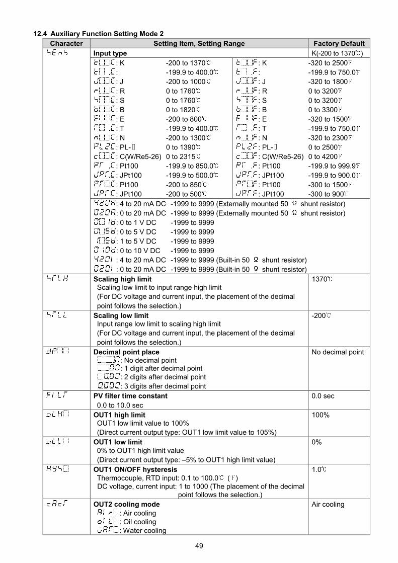
49
12.4 Auxiliary Function Setting Mode 2
Character Setting Item, Setting Range Factory Default
Input type K(-200 to 1370 )
: K -200 to 1370
: -199.9 to 400.0
: J -200 to 1000
: R 0 to 1760
: S 0 to 1760
: B 0 to 1820
: E -200 to 800
: T -199.9 to 400.0
: N -200 to 1300
: PL- 0 to 1390
: C(W/Re5-26) 0 to 2315
: Pt100 -199.9 to 850.0
: JPt100 -199.9 to 500.0
: Pt100 -200 to 850
: JPt100 -200 to 500
: K -320 to 2500
: -199.9 to 750.0
: J -320 to 1800
: R 0 to 3200
: S 0 to 3200
: B 0 to 3300
: E -320 to 1500
: T -199.9 to 750.0
: N -320 to 2300
: PL- 0 to 2500
: C(W/Re5-26) 0 to 4200
: Pt100 -199.9 to 999.9
: JPt100 -199.9 to 900.0
: Pt100 -300 to 1500
: JPt100 -300 to 900
: 4 to 20 mA DC -1999 to 9999 (Externally mounted 50 shunt resistor)
: 0 to 20 mA DC -1999 to 9999 (Externally mounted 50 shunt resistor)
: 0 to 1 V DC -1999 to 9999
: 0 to 5 V DC -1999 to 9999
: 1 to 5 V DC -1999 to 9999
: 0 to 10 V DC -1999 to 9999
: 4 to 20 mA DC -1999 to 9999 (Built-in 50 shunt resistor)
: 0 to 20 mA DC -1999 to 9999 (Built-in 50 shunt resistor)
Scaling high limitScaling low limit to input range high limit
(For DC voltage and current input, the placement of the decimal
point follows the selection.)
1370
Scaling low limitInput range low limit to scaling high limit
(For DC voltage and current input, the placement of the decimal
point follows the selection.)
-200
Decimal point place: No decimal point: 1 digit after decimal point: 2 digits after decimal point
: 3 digits after decimal point
No decimal point
PV filter time constant
0.0 to 10.0 sec
0.0 sec
OUT1 high limitOUT1 low limit value to 100%
(Direct current output type: OUT1 low limit value to 105%)
100%
OUT1 low limit0% to OUT1 high limit value
(Direct current output type: –5% to OUT1 high limit value)
0%
OUT1 ON/OFF hysteresisThermocouple, RTD input: 0.1 to 100.0 ( )DC voltage, current input: 1 to 1000 (The placement of the decimal
point follows the selection.)
1.0
OUT2 cooling mode
: Air cooling: Oil cooling: Water cooling
Air cooling

50
Character Setting Item, Setting Range Factory Default
OUT2 high limit
OUT2 low limit value to 100%
100%
OUT2 low limit
0% to OUT2 high limit value
0%
Overlap/Dead band
Thermocouple, RTD input: –100.0 to 100.0 ( )
DC voltage, current input: 1 to 1000 (The placement of the decimal
point follows the selection.)
0.0
OUT2 ON/OFF hysteresis
Thermocouple, RTD input: 0.1 to 100.0 ( )
DC voltage, current input: 1 to 1000 (The placement of the decimal
point follows the selection)
1.0
Alarm 1 type
: No alarm action
: High limit alarm
: Low limit alarm
: High/Low limits alarm
: High/Low limit range alarm
: Process high alarm
: Process low alarm
: High limit with standby alarm
: Low limit with standby alarm
: High/Low limits with standby alarm
: High/Low limits independent alarm
: High/Low limit range independent alarm
: High/Low limits with standby independent alarm
No alarm action
Alarm 1 Energized/De-energized
: Energized
: De-energized
Energized
Alarm 1 HOLD function
: Not holding
: Holding
Not holding
Alarm 1 hysteresis
Thermocouple, RTD input: 0.1 to 100.0 ( )
DC voltage, current input: 1 to 1000 (The placement of the
decimal point follows the selection.)
1.0
Alarm 1 delay time
0 to 9999 sec0 sec
Direct/Reverse action
: Reverse (Heating) action
: Direct (Cooling) action
Reverse
(Heating) action
AT bias
0 to 50 (0 to 100 ), or 0.0 to 50.0 (0.0 to 100.0 )
20
SVTC bias
20% of the scaling span0
Output status when input errors occur
: Output OFF: OFF(4mA) or OUT1 low limit value.
: Output ON: Outputs a value between OFF (4mA) and ON
(20mA) or between OUT1 low limit value and OUT1 high
limit value, depending on deviation.
Output OFF
Controller/Converter
: Controller
: Converter
Controller

51
12.5 Auxiliary Function Setting Mode 3
Character Setting Item, Setting Range Factory Default
Event input DI allocation No event
Event Input FunctionInput ON
(Closed)
Input OFF
(Open)
No event
Set value memory SV2 SV1
Control ON/OFF Control OFF Control ON
Direct/Reverse action Direct Reverse
Preset output 1 ON/OFF Preset output Usual control
Preset output 2 ON/OFF Preset output Usual control
Auto/Manual control Manual Automatic
Integral action Holding
(Stop)/Usual integral
action
Integral action
Holding (Stop)
Usual integral
action
Set value memory SV1 SV2
Control ON/OFF Control ON Control OFF
Direct/Reverse action Reverse Direct
Preset output 1 ON/OFF Usual control Preset output
Preset output 2 ON/OFF Usual control Preset output
Auto/Manual control Automatic Manual
Integral action Holding
(Stop)/Usual integral
action
Usual integral
action
Integral action
Holding (Stop)
to : Functions work when Event input DI is closed.
to : Functions work when Event input DI is open.
SV2
Scaling low limit to Scaling high limit
0
Alarm 1 value 0 Enabled/Disabled
: Disabled
: Enabled
Disabled
Alarm 1 high limit alarm value
See (Table 12.2-1) on p.48.
(For DC voltage and current input, the placement of the decimal
point follows the selection)
0
Alarm 2 type
: No alarm action
: High limit alarm
: Low limit alarm
: High/Low limits alarm
: High/Low limit range alarm
: Process high alarm
: Process low alarm
: High limit with standby alarm
: Low limit with standby alarm
: High/Low limits with standby alarm
: High/Low limits independent alarm
: High/Low limit range independent alarm
: High/Low limits with standby independent alarm
No alarm action

52
Character Setting Item, Setting Range Factory Default
Alarm 2 value 0 Enabled/Disabled
: Disabled
: Enabled
Disabled
Alarm 2 value
See (Table 12.2-1) on p.48. (For DC voltage and current input, the
placement of the decimal point follows the selection.)
0
Alarm 2 high limit alarm value
See (Table 12.2-1) on p.48. (For DC voltage and current input, the
placement of the decimal point follows the selection.)
0
Alarm 2 Energized/De-energized
: Energized
: De-energized
Energized
Alarm 2 HOLD function
: Not holding
: Holding
Not holding
Alarm 2 hysteresis
Thermocouple, RTD input: 0.1 to 100.0 ( )
DC voltage, current input: 1 to 1000 (The placement of the decimal
point follows the selection.)
1.0
Alarm 2 delay time
0 to 9999 sec
0 sec
Alarm 3 type
: No alarm action
: High limit alarm
: Low limit alarm
: High/Low limits alarm
: High/Low limit range alarm
: Process high alarm
: Process low alarm
: High limit with standby alarm
: Low limit with standby alarm
: High/Low limits with standby alarm
: High/Low limits independent alarm
: High/Low limit range independent alarm
: High/Low limits with standby independent alarm
No alarm action
Alarm 3 value 0 Enabled/Disabled
: Disabled
: Enabled
Disabled
Alarm 3 value
See (Table 12.2-1) on p.48. (For DC voltage and current input, the
placement of the decimal point follows the selection.)
0
Alarm 3 high limit alarm value
See (Table 12.2-1) on p.48. (For DC voltage and current input, the
placement of the decimal point follows the selection.)
0
Alarm 3 Energized/De-energized
: Energized
: De-energized
Energized

53
Character Setting Item, Setting Range Factory Default
Alarm 3 HOLD function
: Not holding
: Holding
Not holding
Alarm 3 hysteresis
Thermocouple, RTD input: 0.1 to 100.0 ( )
DC voltage, current input: 1 to 1000 (The placement of the decimal
point follows the selection.)
1.0
Alarm 3 delay time
0 to 9999 sec
0 sec
Alarm 4 type
: No alarm action
: High limit alarm
: Low limit alarm
: High/Low limits alarm
: High/Low limit range alarm
: Process high alarm
: Process low alarm
: High limit with standby alarm
: Low limit with standby alarm
: High/Low limits with standby alarm
: High/Low limits independent alarm
: High/Low limit range independent alarm
: High/Low limits with standby independent alarm
No alarm action
Alarm 4 value 0 Enabled/Disabled
: Disabled
: Enabled
Disabled
Alarm 4 value
See (Table 12.2-1) on p.48. (For DC voltage and current input, the
placement of the decimal point follows the selection.)
0
Alarm 4 high limit alarm value
See (Table 12.2-1) on p.48. (For DC voltage and current input, the
placement of the decimal point follows the selection.)
0
Alarm 4 Energized/De-energized
: Energized
: De-energized
Energized
Alarm 4 HOLD function
: Not holding
: Holding
Not holding
Alarm 4 hysteresis
Thermocouple, RTD input: 0.1 to 100.0 ( )
DC voltage, current input: 1 to 1000 (The placement of the decimal
point follows the selection.)
1.0
Alarm 4 delay time
0 to 9999 sec
0 sec
Remote/Local
: Local
: Remote
Local
Remote bias
20% of input span
0

54
Character Setting Item, Setting Range Factory Default
External setting input high limit
External setting input low limit to Scaling high limit
1370
External setting input low limit
Scaling low limit to External setting input high limit
–200
SV Rise/Fall rate start type
: SV start
: PV start
SV start
SV rise rate
0 to 9999 /min ( /min) (The placement of the decimal point
follows the selection.)
Thermocouple, RTD input: 0.0 to 999.9 /min ( /min)
DC voltage, current input: 0 to 9999/min
0 /minute
SV fall rate
0 to 9999 /min ( /min) (The placement of the decimal point
follows the selection.)
Thermocouple, RTD input: 0.0 to 999.9 /min ( /min)
DC voltage, current input: 0 to 9999/min
0 /minute
Control output OUT1/EVT
: OUT1
: EVT
OUT1
Heater burnout alarm output Enabled/Disabled
: Disabled
: Enabled
Enabled
Loop break alarm output Enabled/Disabled
: Disabled
: Enabled
Enabled
Alarm 1 output Enabled/Disabled
: Disabled
: Enabled
Enabled
Alarm 2 output Enabled/Disabled
: Disabled
: Enabled
Disabled
Alarm 3 output Enabled/Disabled
: Disabled
: Enabled
Disabled
Alarm 4 output Enabled/Disabled
: Disabled
: Enabled
Disabled
OUT1 MV Preset value
OUT1 low limit to OUT1 high limit
0.0%
OUT2 MV Preset value
OUT2 low limit to OUT2 high limit
0.0%
SUB-MODE key function
: Control output OFF
: Auto/Manual control
: Alarm HOLD cancel
Control output
OFF
Auto/Manual control after power ON
: Automatic control
: Manual control
Automatic
control

55

No. DCL32E4 2018.05