Embed Size (px)
Citation preview

DIMENSIONAL CATALOG
Cast
Iron (Updated July 18, 2018)
© 1977-2018 Charlotte Pipe and Foundry Company
DC-CI
No-Hub Pipe and Fittings
Service Pipe and Fittings
Extra Heavy Pipe and Fittings
Plugs

Cast Iron Pipe and Fitting DimensionsTable of Contents
Page
No-Hub Pipe Dimensions .......................................3&5
No-Hub Fitting Dimensions ................................... 4-43
No-Hub Starter Fitting Detail Drawings .............. 44-50
Service Pipe Dimensions ..................................... 51-53
Service Fitting Dimensions ............................... 54-102
Extra Heavy Pipe Dimensions ......................... 103-105
Extra Heavy Fitting Dimensions ...................... 106-119
Plug Dimensions .................................................... 120
Certification .......................................................... 121
Warranty .............................................................. 123
Charlotte Pipe and “You can’t beat the system” are registered trademarks of Charlotte Pipe and Foundry Company.
Download our Tech Tools App for dimensional info, tech calculators and more on your mobile device.
This catalog accurately reflects dimensional information to the best of our knowledge. If dimensions on your job are critical, please verify dimensional information with our factory.This dimensional catalog accurately reflects our product line at the time the catalog was printed. However, we add and delete items on an ongoing basis to better serve our customers. Please refer to our current list price sheets for an accurate listing of items offered.Charlotte Pipe® products are manufactured to the applicable ASTM standard. Charlotte Pipe and Foundry cannot accept responsibility for the performance, dimensional accuracy, or compatibility of pipe, fittings, gaskets, or couplings not manufactured or sold by Charlotte Pipe and Foundry.

3
TABLE 1DIMENSIONS AND TOLERANCES (IN INCHES) OF SPIGOTS
AND BARRELS FOR NO-HUB PIPE AND FITTINGS
Inside Outside Outside Width Thickness Gasket Barrel Diameter Diameter Spigot of Positioning Diameter Barrel Spigot Bead Barrel Lug Size N B J M (± .13) T-Nom. T-Min. W 11⁄2 1.50 ± .09 1.90 ± .06 1.96 ± .06 .25 .16 .13 1.13 2 1.96 ± .09 2.35 ± .09 2.41 ± .09 .25 .16 .13 1.13 3 2.96 ± .09 3.35 ± .09 3.41 ± .09 .25 .16 .13 1.13 4 3.94 ± .09 4.38 + .09 4.44 ± .09 .31 .19 .15 1.13 – .05 5 4.94 ± .09 5.30 + .09 5.36 ± .09 .31 .19 .15 1.50 – .05 6 5.94 ± .09 6.30 + .09 6.36 ± .09 .31 .19 .15 1.50 – .05 8 7.94 ± .13 8.38 ± .09 8.44 ± .09 .31 .23 .17 2.00 10 10.00 ± .13 10.56 ± .09 10.62 ± .09 .31 .28 .22 2.00 12 11.94 ± .09 12.50 ± .13 12.62 ± .13 .31 .28 .22 2.75 15 15.11 ± .09 15.83 ± .13 16.12 ± .13 .31 .36 .30 2.75
TEN FOOT PIPE BUNDLESNO-HUB PIPE
Size Pieces Weight Height 11⁄2” x 10’ 72 2052 12” 2” x 10’ 54 1906 11” 3” x 10’ 36 1944 14” 4” x 10’ 27 1922 17” 5” x 10’ 24 2342 20” 6” x 10’ 18 2120 23” 8” x 10’ 8 1367 22” 10” x 10’ 6 1528 26” 12” x 10’ 6 1908 29” 15” x 10’ 2 985 19”Weights are approximate and are for shipping purposes only.
No-Hub

4
No-Hub (Standard) Coupling Shield Number Size Width of Clamps
11⁄2 2.13” 2 2 x 11⁄2 2.13” 2 2 2.13” 2 3 x 2 2.13” 2 3 2.13” 2 4 x 3 2.13” 2 4 2.13” 2 5 3.00” 4 6 3.00” 4 8 4.00” 4 10 4.00” 4
PART NO. NH 1
Heavy Duty (HD) Coupling Shield Number Size Width of Clamps
11⁄2 3.00” 4 2 3.00” 4 3 3.00” 4 4 3.00” 4 5 4.00” 6 6 4.00” 6 8 4.00” 6 10 4.00” 6
PART NO. SDC 4
No-Hub Pipe and Fittings
Heavy Duty (MD) Coupling Shield Number Size Width of Clamps
11⁄2 3.00” 4 2 3.00” 4 3 3.00” 4 4 3.00” 4 5 4.00” 6 6 4.00” 6 8 4.00” 6 10 4.00” 6
PART NO. MDC 2

5
Long Quarter Bend Size D E Weight
2 x 12 12 41⁄2 5.4 2 x 18 18 41⁄2 8.8 2 x 24 24 41⁄2 10.7 3 x 12 12 5 8.5 4 x 12 12 51⁄2 11.2
No-Hub Pipe - Ten Feet Laying Length Size Weight
11⁄2” x 10’ 28.5 2” x 10’ 35.0 3” x 10’ 54.0 4” x 10’ 71.2 5” x 10’ 97.6 6” x 10’ 117.8 8” x 10’ 170.9 10” x 10’ 254.6 12” x 10’ 318.1 15” x 10’ 492.6
Quarter Bend Size D Weight
11⁄2 41⁄4 1.7 2 41⁄2 2.2 3 5 3.7 4 51⁄2 6.5 5 61⁄2 9.3 6 7 15.0 8 81⁄2 23.1 4 x 3 51⁄2 5.5
PART NO. NH 2
PART NO. NH 4
No-Hub Pipe and Fittings
NO-HUB
Heavy Duty Coupling Shield Number Size Width of Clamps
12 5.50” 6 15 5.50” 6
PART NO. HD 1

6
Double Quarter Bend Size D Weight
2 41⁄2 4.5 3 5 7.1 4 51⁄2 9.7
PART NO. NH 8A
Quarter Bend with Side Opening Size E D Weight
3 x 2 31⁄4 4 5.1 4 x 2 33⁄4 45⁄16 7.5
Quarter Bend with Heel Opening Size D E Weight
3 x 2 5 27⁄8 5.6 4 x 2 51⁄2 31⁄4 7.2
PART NO. NH 8
PART NO. NH 6
Tapped Quarter Bend Size D E Weight
11⁄2 x 11⁄2 3 2 1.9 2 x 11⁄4 31⁄4 21⁄4 2.0 2 x 11⁄2 31⁄4 21⁄4 1.8 2 x 2 31⁄4 21⁄4 2.9
PART NO. NH 4A
No-Hub Pipe and Fittings

7
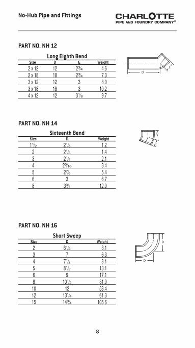
Eighth Bend Size D Weight
11⁄2 25⁄8 1.5 2 23⁄4 1.5 3 3 2.9 4 31⁄8 4.0 5 37⁄8 7.4 6 41⁄16 9.1 8 5 14.9 10 515⁄16 31.7 12 69⁄16 31.6 15 713⁄16 62.0
Sixth Bend Size D Weight
2 31⁄4 2.2 3 31⁄2 3.0 4 313⁄16 5.3
Fifth Bend Size D Weight
2 311⁄16 2.3 3 41⁄16 3.7 4 47⁄16 6.1
PART NO. NH 12
PART NO. NH 10
PART NO. NH 9
No-Hub Pipe and Fittings
NO-HUB
Extended Quarter Bend with Low Heel Outlet
Size D E Weight
3 x 2 5 101⁄2 7.8
PART NO. NH 8B
8
Short Sweep Size D Weight
2 61⁄2 3.1 3 7 6.3 4 71⁄2 8.1 5 81⁄2 13.1 6 9 17.1 8 101⁄2 31.0 10 12 53.4 12 131⁄4 61.3 15 143⁄4 105.6
PART NO. NH 16
No-Hub Pipe and Fittings
Sixteenth Bend Size D Weight
11⁄2 21⁄8 1.2 2 21⁄8 1.4 3 21⁄4 2.1 4 25⁄16 3.4 5 27⁄8 5.4 6 3 6.7 8 33⁄4 12.0
PART NO. NH 14
Long Eighth Bend Size D E Weight
2 x 12 12 23⁄4 4.6 2 x 18 18 23⁄4 7.3 3 x 12 12 3 8.0 3 x 18 18 3 10.2 4 x 12 12 31⁄8 9.7
PART NO. NH 12

9
Long Sweep Size D Weight
11⁄2 91⁄4 4.4 2 91⁄2 5.8 3 10 9.4 4 101⁄2 12.3 5 111⁄2 18.6 6 12 23.3
PART NO. NH 18
No-Hub Pipe and Fittings
Reducing Long Sweep Size D Weight
4 x 3 101⁄2 12.4
PART NO. NH 18
NO-HUB
Extended Short Sweep Size E F Weight
2 x 18 61⁄2 18 8.0 2 x 24 61⁄2 24 11.0 2 x 34 61⁄2 34 13.9
PART NO. EZS 14

10
No-Hub Pipe and Fittings
Wye Size D F G Weight
11⁄2 x 11⁄2 4 6 2 2.5 2 x 2 45⁄8 65⁄8 2 3.3 3 x 11⁄2 45⁄8 61⁄8 115⁄16 4.4 3 x 2 55⁄16 65⁄8 11⁄2 3.4 3 53⁄4 8 21⁄4 4.6 4 x 2 6 65⁄8 1 5.1 4 x 3 61⁄2 8 111⁄16 7.3 4 71⁄16 91⁄2 27⁄16 9.1 5 x 2 71⁄2 81⁄16 15⁄16 8.8 5 x 3 8 911⁄16 111⁄16 10.5 5 x 4 81⁄2 113⁄16 27⁄16 13.1 5 91⁄2 125⁄8 31⁄8 15.1 6 x 2 81⁄4 85⁄16 1⁄2 9.8 6 x 3 83⁄4 93⁄4 11⁄4 12.5 6 x 4 91⁄4 113⁄16 115⁄16 14.6 6 x 5 101⁄4 121⁄2 29⁄16 17.6 6 103⁄4 141⁄16 35⁄16 19.7 8 x 3 913⁄16 915⁄16 1⁄8 17.5 8 x 4 103⁄8 117⁄16 15⁄16 22.0 8 x 5 113⁄8 1213⁄16 15⁄8 23.9 8 x 6 1113⁄16 143⁄16 25⁄16 28.3 8 133⁄8 171⁄8 33⁄4 36.3 10 x 4 1111⁄16 125⁄8 3⁄4 32.9 10 x 6 131⁄8 157⁄16 23⁄16 42.1 10 x 8 1411⁄16 183⁄8 35⁄8 56.1 10 161⁄2 211⁄2 51⁄16 74.9 12 193⁄4 251⁄2 53⁄4 97.0 15 231⁄4 30 63⁄4 189.5
PART NO. NH 20

11
Double Wye Size D F Weight
2 45⁄8 65⁄8 4.5 3 x 2 55⁄16 65⁄8 5.5 3 53⁄4 8 7.9 4 x 2 6 65⁄8 6.5 4 x 3 61⁄2 8 8.8 4 71⁄16 91⁄2 12.1 5 x 4 81⁄2 113⁄16 15.7 6 x 4 91⁄4 113⁄16 16.4 6 103⁄4 141⁄16 27.4 8 133⁄8 171⁄8 45.3 8 x 4 103⁄8 117⁄16 23.0 8 x 6 1113⁄16 143⁄16 31.3
PART NO. NH 21
NO-HUB
No-Hub Pipe and Fittings
Upright Wye Size H E F G Weight
2 81⁄4 51⁄2 7 2 4.8 3 x 2 83⁄16 51⁄2 7 11⁄2 5.7 3 87⁄16 51⁄2 83⁄8 23⁄16 9.5 4 x 2 81⁄4 51⁄2 7 1 7.7 4 x 3 87⁄16 51⁄2 83⁄8 111⁄16 10.1 4 91⁄8 6 93⁄4 27⁄16 12.9 5 x 2 9 61⁄8 8 1 11.0 5 117⁄16 71⁄8 123⁄4 23⁄4 19.9
PART NO. NH 21A

12
Extended Combination Size E F G Weight
2 x 24 63⁄16 253⁄8 24 12.0 2 x 36 63⁄16 36 343⁄4 15.4
PART NO. EZS 15
Combination Size D E F Weight
11⁄2 43⁄4 53⁄8 6 3.1 2 x 11⁄2 5 57⁄8 6 3.4 2 53⁄8 61⁄8 65⁄8 3.5 3 x 11⁄2 51⁄2 63⁄4 65⁄8 5.0 3 x 2 51⁄2 63⁄4 65⁄8 5.7 3 75⁄16 8 8 8.5 4 x 2 51⁄2 71⁄4 65⁄8 6.6 4 x 3 71⁄4 81⁄2 8 9.5 4 91⁄4 10 91⁄2 13.7 5 x 2 515⁄16 73⁄4 81⁄16 8.5 5 x 3 73⁄4 9 911⁄16 12.0 5 x 4 93⁄4 101⁄2 113⁄16 17.1 5 113⁄4 121⁄2 125⁄8 19.7 6 x 2 6 81⁄4 85⁄16 12.0 6 x 3 713⁄16 91⁄2 93⁄4 14.7 6 x 4 93⁄4 11 113⁄16 18.4 6 x 5 1111⁄16 13 121⁄2 23.4 6 135⁄8 143⁄8 141⁄16 30.0 8 x 4 97⁄16 115⁄16 113⁄16 25.1 8 x 6 12 133⁄8 1315⁄16 35.4 8 143⁄4 159⁄16 1615⁄16 49.3
PART NO. NH 22
No-Hub Pipe and Fittings

13
Double Combination Size D E F Weight
2 53⁄8 61⁄8 65⁄8 6.3 3 x 2 51⁄2 63⁄4 65⁄8 7.7 3 75⁄16 8 8 11.8 4 x 2 51⁄2 71⁄4 65⁄8 8.3 4 x 3 71⁄4 81⁄2 8 13.7 4 91⁄4 10 91⁄2 20.5
Tapped Wye Size D F Weight
2 x 11⁄2 51⁄16 65⁄8 3.4 2 x 2 51⁄16 65⁄8 4.6 3 x 11⁄2 53⁄4 65⁄8 5.1 3 x 2 513⁄16 65⁄8 5.3 4 x 11⁄2 67⁄16 65⁄8 6.0 4 x 2 61⁄2 65⁄8 7.2
PART NO. NH 24
PART NO. NH 26
No-Hub Pipe and Fittings
NO-HUB
Tapped Double Wye Size D F Weight
2 x 11⁄2 51⁄16 65⁄8 5.6
PART NO. NH 27
14
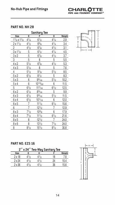
Sanitary Tee Size E F D Weight
11⁄2 x 11⁄2 41⁄4 61⁄2 41⁄4 2.9 2 x 11⁄2 41⁄2 65⁄8 41⁄4 3.4 2 41⁄2 67⁄8 41⁄2 3.1 3 x 11⁄2 5 61⁄2 41⁄4 4.5 3 x 2 5 67⁄8 41⁄2 3.7 3 5 8 5 5.5 4 x 2 51⁄2 67⁄8 41⁄2 5.3 4 x 3 51⁄2 8 5 7.6 4 51⁄2 91⁄8 51⁄2 8.5 5 x 2 61⁄2 81⁄2 5 8.3 5 x 3 6 95⁄16 51⁄2 10.2 5 x 4 6 1013⁄32 6 11.5 5 61⁄2 117⁄16 61⁄2 12.5 6 x 2 61⁄2 83⁄16 5 9.9 6 x 3 61⁄2 93⁄16 51⁄2 11.5 6 x 4 61⁄2 101⁄16 6 12.0 6 x 5 7 111⁄2 61⁄2 15.6 6 7 121⁄2 7 12.9 8 x 3 71⁄2 103⁄8 6 17.9 8 x 4 71⁄2 111⁄2 61⁄2 21.6 8 x 5 8 121⁄2 7 24.0 8 x 6 8 131⁄2 71⁄2 24.0 8 81⁄2 151⁄2 81⁄2 30.8
PART NO. NH 28
2” x 24” Two-Way Sanitary Tee Size E H F Weight
2 x 18 41⁄2 41⁄2 18 7.8 2 x 24 41⁄2 41⁄2 24 10.4 2 x 36 41⁄2 41⁄2 36 15.6
PART NO. EZS 16
No-Hub Pipe and Fittings

15
Sanitary Tee with 2” 90° Sanitary Opening Above Center
(New Orleans Code) Size C D E F G Weight
3 (L) 41⁄2 6 5 81⁄2 5 6.7 3 (R) 41⁄2 6 5 81⁄2 5 6.3 4 (L) 5 61⁄2 51⁄2 93⁄16 51⁄2 8.6 4 (R) 5 61⁄2 51⁄2 93⁄16 51⁄2 8.5
Sanitary Tee with 2” Side InletsRight Hand and Left Hand
Size E F D Weight
4 x 4 w/RH & LH 59⁄16 91⁄8 51⁄2 10.9
PART NO. NH 31
PART NO. NH 32
Sanitary Cross Size E F D Weight
11⁄2 41⁄4 61⁄2 41⁄2 3.6 2 41⁄2 67⁄8 41⁄2 5.0 3 x 2 5 67⁄8 41⁄2 6.2 3 5 8 5 7.6 4 x 2 51⁄2 67⁄8 41⁄2 7.3 4 x 3 51⁄2 8 5 8.5 4 51⁄2 91⁄8 51⁄2 11.0 5 x 4 6 1013⁄32 6 13.4 6 x 4 61⁄2 101⁄16 6 14.0 6 7 121⁄2 7 21.0 8 x 4 71⁄2 111⁄2 61⁄2 23.0 8 81⁄2 151⁄2 81⁄2 37.9
PART NO. NH 30
No-Hub Pipe and Fittings
NO-HUB

16
Sanitary Cross with Two 2” 90° Sanitary Openings Above Center
(New Orleans Code) Size C D E F G Weight
3 41⁄2 6 5 81⁄2 5 9.0 4 5 61⁄2 51⁄2 93⁄16 51⁄2 11.9
PART NO. NH 33A
PART NO. NH 33C
Sanitary Cross with 2” 90° Sanitary Openings Above Center
(New Orleans Code) Size C D E F G Weight
4 5 61⁄2 51⁄2 93⁄16 51⁄2 10.8
No-Hub Pipe and Fittings
Sanitary Tee with 2” 45° Sanitary Opening Above Center
(New Orleans Code) Size D E F G Weight
3 (L) 6 5 81⁄2 5 8.2 3 (R) 6 5 81⁄2 5 7.8 3 (R&L) 6 5 81⁄2 5 9.1 4 (L) 61⁄2 51⁄2 93⁄16 51⁄2 9.6 4 (R) 61⁄2 51⁄2 93⁄16 51⁄2 9.4
PART NO. NH 32B

17
Sanitary Cross with Two 2” 45° Sanitary Openings Same Side
(New Orleans Code) Size D E F G Weight
3 6 5 81⁄2 5 9.8 4 51⁄2 51⁄2 91⁄16 51⁄2 13.8
Sanitary Cross with 3” Vent and Two 2” 45° Inlets
Size A B C F G Weight
4x3x4x2x2 33⁄4 51⁄4 43⁄4 101⁄2 61⁄2 24.0
PART NO. NH 33F
PART NO. NH 33G
No-Hub Pipe and Fittings
NO-HUB
Sanitary Tapped Tee Size D E F Weight
11⁄2 x 11⁄4 31⁄4 29⁄16 511⁄16 2.3 11⁄2 x 11⁄2 31⁄4 29⁄16 511⁄16 2.5 2 x 11⁄4 31⁄4 213⁄16 511⁄16 2.8 2 x 11⁄2 31⁄4 213⁄16 511⁄16 3.1 2 x 2 33⁄4 31⁄16 63⁄8 3.8 3 x 11⁄4 31⁄4 35⁄16 511⁄16 3.7 3 x 11⁄2 31⁄4 35⁄16 511⁄16 3.6 3 x 2 33⁄4 39⁄16 63⁄8 4.9 3 x 3 47⁄8 41⁄8 8 7.3 4 x 11⁄4 31⁄4 313⁄16 511⁄16 4.0 4 x 11⁄2 31⁄4 33⁄4 511⁄16 4.8 4 x 2 33⁄4 41⁄16 63⁄8 5.8 4 x 3 41⁄2 43⁄8 8 8.4 5 x 11⁄2 33⁄4 45⁄16 73⁄16 6.5 5 x 2 41⁄4 49⁄16 8 9.3 6 x 11⁄2 33⁄4 413⁄16 63⁄4 8.4 6 x 2 41⁄4 51⁄16 77⁄16 9.2
PART NO. NH 34

18
2” x 227⁄8” Extended Tapped Sanitary Tee
Size H F Weight
2 x 11⁄2 x 227⁄8 31⁄4 227⁄8 9.6 2 x 2 x 227⁄8 33⁄4 227⁄8 9.2
PART NO. EZS 17
Sanitary Tapped Cross Size D E F Weight
11⁄2 x 11⁄2 31⁄4 29⁄16 511⁄16 3.4 2 x 11⁄4 31⁄4 213⁄16 511⁄16 3.9 2 x 11⁄2 31⁄4 213⁄16 511⁄16 4.0 2 x 2 33⁄4 31⁄16 63⁄8 5.3 3 x 11⁄2 31⁄4 35⁄16 511⁄16 4.3 3 x 2 33⁄4 39⁄16 63⁄8 6.1 4 x 11⁄2 31⁄4 33⁄4 511⁄16 5.5 4 x 2 33⁄4 41⁄16 63⁄8 6.9
PART NO. NH 35
Sanitary Tapped Tee Size H F Weight
2 x 11⁄2 x 31 111⁄4 31 12.6 2 x 2 x 31 111⁄4 31 13.6
PART NO. EZS 27
No-Hub Pipe and Fittings

19
2” x 227⁄8” Extended Tapped Sanitary Cross
Size H F Weight
2 x 11⁄2 x 227⁄8 31⁄4 227⁄8 10.0 2 x 2 x 227⁄8 33⁄4 227⁄8 11.9
PART NO. EZS 18
No-Hub Pipe and Fittings
Double Vertical Sanitary Tapped Tee
Size E F G H Weight
2 x 11⁄2 213⁄16 93⁄4 41⁄2 31⁄4 4.8
Sanitary Tapped Cross Size H F Weight
2 x 11⁄2 x 31 111⁄4 31 15.0 2 x 2 x 31 111⁄4 31 15.0
PART NO. EZS 28
PART NO. NH 35B
NO-HUB

20
PART NO. NH 36
Increaser-Reducer Size F Weight
2 x 3 8 3.8 2 x 4 8 4.4 3 x 4 8 5.0
PART NO. NH 40
No-Hub Pipe and Fittings
Test Tee Less Plug
and PART NO. NH 36S
Test Tee with SouthernRaised-Head Brass Plug Installed
(2” through 8” only) IPS Size Tap E F D D’ Weight
2 2 2 63⁄8 33⁄16 33⁄16 3.0 3 3 211⁄16 73⁄4 37⁄8 37⁄8 5.8 4 4 3 87⁄8 47⁄16 47⁄16 9.2 5 5 41⁄2 111⁄2 53⁄4 53⁄4 15.2 6 6 5 121⁄2 61⁄4 61⁄4 22.0 8 8 6 151⁄4 75⁄8 75⁄8 37.1 10 10 61⁄2 20 10 10 59.7 4 x 3 31⁄2 27⁄8 91⁄2 5 41⁄2 8.0
21
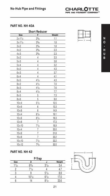
Short Reducer Size F Weight
2 x 11⁄2 35⁄8 1.1 3 x 11⁄2 35⁄8 1.8 3 x 2 35⁄8 1.8 4 x 2 35⁄8 2.3 4 x 3 35⁄8 2.3 5 x 2 4 3.3 5 x 3 4 3.8 5 x 4 4 3.2 6 x 2 4 4.3 6 x 3 4 3.7 6 x 4 4 4.1 6 x 5 41⁄2 4.3 8 x 2 41⁄2 7.0 8 x 3 41⁄2 7.6 8 x 4 41⁄2 7.7 8 x 5 5 7.3 8 x 6 5 8.0 10 x 4 51⁄2 12.5 10 x 6 6 13.3 10 x 8 6 14.9 12 x 4 61⁄2 19.1 12 x 6 61⁄2 18.3 12 x 8 7 17.3 12 x 10 71⁄2 18.9 15 x 4 7 30.0 15 x 6 7 31.8 15 x 8 7 32.2 15 x 10 71⁄2 32.2 15 x 12 73⁄4 30.5
PART NO. NH 40A
No-Hub Pipe and Fittings
NO-HUB
P-Trap Size D J Weight
11⁄2 63⁄4 31⁄2 3.4 2 71⁄2 4 4.7 3 9 51⁄2 8.9 4 101⁄2 61⁄2 17.0 6 14 81⁄2 33.6
PART NO. NH 42

22
P Trap with 1⁄2” Tap in Heel Size C D E J Weight
2 4 71⁄2 2 4 4.7 3 5 9 2 51⁄2 10.8 4 6 101⁄2 2 61⁄2 18.8
PART NO. NH 43
No-Hub Pipe and Fittings
Long P-Trap Size D J Weight
2 x 12 12 4 6.1 2 x 18 18 4 8.0
PART NO. NH 42
P-Trap, Reducing Size D J Weight
3 x 2 9 51⁄2 10.0
PART NO. NH 42A
P Trap with 1⁄2” Tap in Heel Size C D E J Weight
6 8 14 23⁄4 81⁄2 33.6
PART NO. NH 42B

23
P-Trap with 11⁄2” Tapped Side Inlet Size H F Weight
2 53⁄16 71⁄2 6.2
PART NO. EZS 9
No-Hub Pipe and Fittings
P-Trap with 2” Side Inlet Size C D J Weight
2 13⁄16 71⁄2 31⁄16 6.4
PART NO. EZS 10
NO-HUB
Deep Seal P Trap Size C D J Weight
2 4 71⁄2 7 6.6 3 5 9 7 11.0 4 6 101⁄2 8 18.6
PART NO. NH 44A
P-Trap with Tapped Inlet Size C D J Weight
11⁄2 x 11⁄2 31⁄2 63⁄4 31⁄2 3.0 2 x 11⁄2 4 71⁄2 4 4.5 2 x 2 4 71⁄2 4 5.4
PART NO. NH 44
24
No-Hub Pipe and Fittings
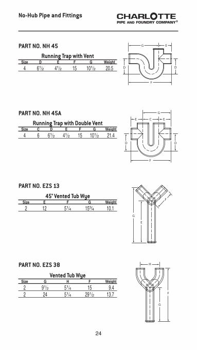
Vented Tub Wye Size G H F Weight
2 91⁄2 51⁄4 15 9.4 2 24 51⁄4 291⁄2 13.7
PART NO. EZS 38
Running Trap with Double Vent Size C D E F G Weight
4 6 61⁄2 41⁄2 15 101⁄2 21.4
PART NO. NH 45A
45° Vented Tub Wye Size E F G Weight
2 12 51⁄4 153⁄4 10.1
PART NO. EZS 13
Running Trap with Vent Size D E F G Weight
4 61⁄2 41⁄2 15 101⁄2 20.5
PART NO. NH 45
25
No-Hub Pipe and Fittings
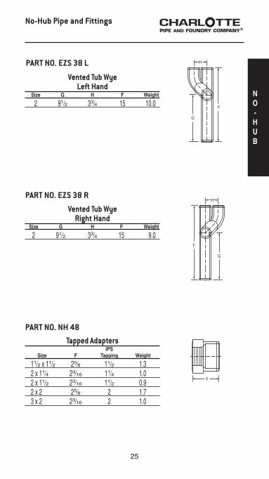
Vented Tub WyeRight Hand
Size G H F Weight
2 91⁄2 33⁄4 15 9.0
PART NO. EZS 38 R
NO-HUB
Vented Tub WyeLeft Hand
Size G H F Weight
2 91⁄2 33⁄4 15 10.0
PART NO. EZS 38 L
Tapped Adapters IPS Size F Tapping Weight
11⁄2 x 11⁄2 25⁄8 11⁄2 1.3 2 x 11⁄4 23⁄16 11⁄4 1.0 2 x 11⁄2 23⁄16 11⁄2 0.9 2 x 2 25⁄8 2 1.7 3 x 2 23⁄16 2 1.0
PART NO. NH 48
26
No-Hub Pipe and Fittings
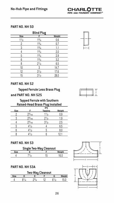
Two-Way Cleanout Size D E F G Weight
4 81⁄4 23⁄4 12 61⁄2 15.0
PART NO. NH 53A
Single Two-Way Cleanout Size E F Weight
4 71⁄2 15 16.0
PART NO. NH 53
Tapped Ferrule Less Brass Plug
PART NO. NH 52
Blind Plug Size F Weight
11⁄2 13⁄4 0.6 2 13⁄4 0.7 3 13⁄4 1.1 4 13⁄4 2.0 5 13⁄4 2.9 6 13⁄4 3.2 8 21⁄4 6.5 10 3 14.7 12 31⁄2 17.6 15 31⁄2 28.0
PART NO. NH 50
and PART NO. NH 52STapped Ferrule with Southern
Raised-Head Brass Plug Installed IPS Size F Tapping Weight
2 23⁄16 11⁄2 0.9 3 23⁄16 21⁄2 1.9 4 23⁄16 31⁄2 2.5 5 41⁄2 4 6.5 6 41⁄2 5 8.0 8 41⁄2 6 12.1

27
No-Hub Pipe and Fittings
NO-HUB
H
D
F
Horizontal Twin Tapped Tee Size A D F H Weight
3 x 11⁄2 13⁄8 4 7 3 7.3 4 x 11⁄2 13⁄8 4 7 3 8.0
PART NO. NH 57
Notched and Slotted Closet Collar Size D E F A Weight
4 x 3 31⁄2 33⁄8 71⁄4 47⁄32 3.3 4 x 3 8 327⁄64 71⁄4 4 6.1 4 x 4 4 43⁄8 71⁄4 49⁄64 4.7 4 x 4 8 43⁄8 71⁄4 47⁄32 7.0
PART NO. NH 56
Two-Way Baffle Cleanout Size D F Weight
3 x 3 x 4 15 9 14.2 4 x 4 x 4 183⁄8 91⁄2 22.0
PART NO. NH 54

28
No-Hub Pipe and Fittings
Vented Closet Teewith 2” Top Vent
(Left or Right; Designed for use below the floor; Fitting does not require a baffle)
Size B C D E F G Wt.
4x4x2x4(L) 41⁄4 51⁄4 33⁄4 4 101⁄2 33⁄4 12.1 4x4x2x4(R) 41⁄4 51⁄4 33⁄4 4 101⁄2 33⁄4 11.6
PART NO. NH 457
Vented Closet Cross with 2” Top Vent(Designed for use below the floor;
Fitting has a baffle) Size B C D E F G Wt
4x4x2x4x4 41⁄4 51⁄4 33⁄4 4 101⁄2 33⁄4 15.0
PART NO. NH 463
Vented Closet Teewith 2” Top Vent and 2” Side Opening
(Left or Right; Designed for use below the floor;Fitting does not require a baffle)
Size A B C D E F G Wt.
4x4x2x2x4(L) 81⁄8 41⁄4 51⁄4 71⁄2 4 101⁄2 33⁄4 12.3 4x4x2x2x4(R) 81⁄8 41⁄4 51⁄4 71⁄2 4 101⁄2 33⁄4 12.2
PART NO. NH 458T
T Additional drawing available in Detail Drawing Section

29
No-Hub Pipe and Fittings
Vented Closet Cross with 2” Top Vent and 2” Side Opening
(Designed for use below the floor;Fitting has a baffle)
Size A B C D E F G Wt.
4x4x2x2x4x4 81⁄8 41⁄4 51⁄4 71⁄2 4 101⁄2 33⁄4 15.6
PART NO. NH 464
NO-HUB
PART NO. NH 502T
4” No Hub Prison Fitting with 2” Top Vent(Designed for use above the floor; Baffle helps prevent
passage of contraband between cells) Part No. Size UPC# 611942- A C F G Weight
NH 502 4 Less Tap 00639 8 5 1⁄4 12 8 20.3 NH 502 4 With Tap 00640 8 5 1⁄4 12 8 20.8 NH 502 4x3 Less Tap 11119 8 5 1⁄4 12 8 23.4 NH 502 4x3 With Tap 11120 8 5 1⁄4 12 8 23.4
T Additional drawing available in Detail Drawing Section
30
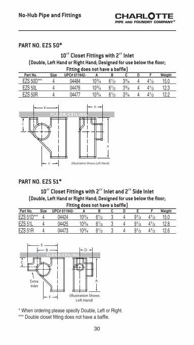
PART NO. EZS 50*
10” Closet Fittings with 2” Inlet(Double, Left Hand or Right Hand; Designed for use below the floor;
Fitting does not have a baffle) Part No. Size UPC# 611942- A B C D F Weight
EZS 50D*** 4 04484 103⁄4 61⁄2 33⁄4 4 41⁄2 15.0 EZS 50L 4 04476 103⁄4 61⁄2 33⁄4 4 41⁄2 12.3 EZS 50R 4 04477 103⁄4 61⁄2 33⁄4 4 41⁄2 12.2
10” Closet Fittings with 2” Inlet and 2” Side Inlet(Double, Left Hand or Right Hand; Designed for use below the floor;
Fitting does not have a baffle) Part No. Size UPC# 611942- A B C D E F Weight
EZS 51D*** 4 04424 103⁄4 61⁄2 3 4 91⁄2 41⁄2 15.0EZS 51L 4 04425 103⁄4 61⁄2 3 4 91⁄2 41⁄2 12.8 EZS 51R 4 04473 103⁄4 61⁄2 3 4 91⁄2 41⁄2 12.6
No-Hub Pipe and Fittings
PART NO. EZS 51*
* When ordering please specify Double, Left or Right.*** Double closet fitting does not have a baffle.

31
NO-HUB
No-Hub Pipe and Fittings
RIGHT HAND CROSS-OVER ILLUSTRATED
With the vented end toward you, hold the fitting so that you are looking into its length with the curved side up. If the vent is on your left side, it is a Left Hand fitting. If the vent is on your right side, it is a Right Hand fitting.
HOW TO DETERMINE RIGHT or LEFT HAND CROSS-OVER
Note: Our crossovers are designed for use with EZS starter fittings, that is for the vent and stack centerline to be 61⁄2”
2” Vent Cross-Over, Plain (No Outlets)
U.P.C. No. 611942 Size A C F Weight
04429 2 x 183⁄8 47⁄8 93⁄16 183⁄8 8.1
PART NO. EZS 7
Note: VENT CROSS-OVER for use with EZS-50 through 800 Series fittings.
Specify Right, Left, Plain or Double.
2” Vent Cross-Over, Double (2 Inlets) U.P.C. No. 611942 Size A B C F Weight
04430 2 x 183⁄8 47⁄8 61⁄2 93⁄16 183⁄8 8.0
PART NO. EZS 7D

32
2” Vent Cross-Over with Left Hand Inlet
U.P.C. No. 611942 Size A B C F Weight
04431 2 x 183⁄8 47⁄8 61⁄2 93⁄16 183⁄8 8.2
PART NO. EZS 7L
No-Hub Pipe and Fittings
Figure One Size E F D Weight
2 x 11⁄2 33⁄16 7 47⁄8 5.3
PART NO. EZS 1
2” Vent Cross-Over with Right Hand Inlet
U.P.C. No. 611942 Size A B C F Weight
04432 2 x 183⁄8 47⁄8 61⁄2 93⁄16 183⁄8 8.4
PART NO. EZS 7R

33
NO-HUB
No-Hub Pipe and Fittings
Figure Five Double Fixture Fitting Size D E F G Weight
2 61⁄2 5 8 113⁄16 7.0 3 87⁄8 69⁄16 101⁄8 2 10.5 3 x 2 x 3 x 3 87⁄8 69⁄16 91⁄4 2 10.7 4 101⁄4 73⁄4 12 115⁄16 22.5 4 x 2 x 4 x 4 101⁄4 73⁄4 111⁄2 115⁄16 19.8
PART NO. NH 25
* When ordering please specify Double, Left or Right.** Double fitting has a baffle.
PART NO. EZS 6*Figure Six
(Double, Left Hand or Right Hand; Designed for use below the floor) Part No. Size C D E F H Weight
EZS 6D** 3x2 41⁄8 79⁄16 51⁄16 11 37⁄16 13.0 EZS 6D** 4x2 41⁄2 9 61⁄2 13 4 23.1
EZS 6L 3x2 41⁄8 79⁄16 51⁄16 11 37⁄16 11.4 EZS 6L 4x2 41⁄2 9 61⁄2 13 4 18.0
EZS 6R 3x2 41⁄8 79⁄16 51⁄16 11 37⁄16 11.4 EZS 6R 4x2 41⁄2 9 61⁄2 13 4 18.0

34
No-Hub Pipe and Fittings
* When ordering please specify Double, Left or Right.** Double fitting has a baffle.
Figure Eight Double Fixture Fitting, Extended**
(Designed for Use Below the Floor) Size D E F H Weight
4 x 2 9 61⁄2 13 8 23.4
PART NO. EZS 8A
PART NO. EZS 8*Figure Eight
(Double, Left Hand or Right Hand; Designed for use below the floor) Part No. Size C D E F H Weight EZS 8D** 3x2 41⁄8 79⁄16 51⁄16 11 37⁄16 13.0
EZS 8L 3x2 41⁄8 79⁄16 51⁄16 11 37⁄16 12.5 EZS 8L 4x2 41⁄2 9 61⁄2 13 4 19.8
EZS 8R 3x2 41⁄8 79⁄16 51⁄16 11 37⁄16 12.5 EZS 8R 4x2 41⁄2 9 61⁄2 13 4 19.8

35
NO-HUB
No-Hub Pipe and Fittings
PART NO. EZS 100*
16” Closet Fittings with 2” Inlets(Double, Left Hand or Right Hand; Designed for use below the floor)
Part No. Size A B C D E M Weight EZS 100D 4x16 163⁄4 5 41⁄2 61⁄2 51⁄2 5 22.0
EZS 100L 4x16 163⁄4 5 41⁄2 61⁄2 51⁄2 5 20.0
EZS 100R 4x16 163⁄4 5 41⁄2 61⁄2 51⁄2 5 21.1
M & B dimensions must be measured from the bottom
of the fitting.
* When ordering please specify Double, Left or Right.

36
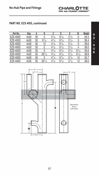
PART NO. EZS 400*T
No-Hub Pipe and Fittings
* When ordering please specify Double, Left or Right.T Additional drawing available in Detail Drawing Section
30” Closet Fittings with 2” Inlet(Double, Left Hand or Right Hand; Designed for use in the floor)
Part No. Size A B C D E M Weight EZS 400L 4x30 30 0 41⁄2 61⁄2 51⁄2 0 34.0 EZS 400L 4x30 30 61⁄2 41⁄2 61⁄2 51⁄2 0 34.2 EZS 400L 4x30 30 12 41⁄2 61⁄2 51⁄2 0 37.8 EZS 400L 4x30 30 261⁄2 41⁄2 61⁄2 51⁄2 0 34.3 EZS 400L 4x30 30 0 41⁄2 61⁄2 51⁄2 4 34.0 EZS 400L 4x30 30 261⁄2 41⁄2 61⁄2 51⁄2 4 34.0 EZS 400L 4x30 30 0 41⁄2 61⁄2 51⁄2 61⁄2 33.1 EZS 400L 4x30 30 61⁄2 41⁄2 61⁄2 51⁄2 61⁄2 34.0 EZS 400L 4x30 30 261⁄2 41⁄2 61⁄2 51⁄2 61⁄2 36.8 EZS 400L 4x30 30 0 41⁄2 61⁄2 51⁄2 12 31.0 EZS 400L 4x30 30 261⁄2 41⁄2 61⁄2 51⁄2 12 30.0
EZS 400R 4x30 30 0 41⁄2 61⁄2 51⁄2 0 32.9 EZS 400R 4x30 30 61⁄2 41⁄2 61⁄2 51⁄2 0 34.5 EZS 400R 4x30 30 12 41⁄2 61⁄2 51⁄2 0 37.1 EZS 400R 4x30 30 261⁄2 41⁄2 61⁄2 51⁄2 0 33.8 EZS 400R 4x30 30 0 41⁄2 61⁄2 51⁄2 4 34.0 EZS 400R 4x30 30 261⁄2 41⁄2 61⁄2 51⁄2 4 28.9 EZS 400R 4x30 30 0 41⁄2 61⁄2 51⁄2 61⁄2 33.9 EZS 400R 4x30 30 61⁄2 41⁄2 61⁄2 51⁄2 61⁄2 35.4 EZS 400R 4x30 30 261⁄2 41⁄2 61⁄2 51⁄2 61⁄2 35.4 EZS 400R 4x30 30 0 41⁄2 61⁄2 51⁄2 12 31.0 EZS 400R 4x30 30 261⁄2 41⁄2 61⁄2 51⁄2 12 28.5
(EZS 400 is continued on the following page.)
37
No-Hub Pipe and Fittings
Part No. Size A B C D E M Weight EZS 400D 4x30 30 0 41⁄2 61⁄2 51⁄2 0 29.3 EZS 400D 4x30 30 61⁄2 41⁄2 61⁄2 51⁄2 0 36.4 EZS 400D 4x30 30 12 41⁄2 61⁄2 51⁄2 0 39.6 EZS 400D 4x30 30 0 41⁄2 61⁄2 51⁄2 4 38.0 EZS 400D 4x30 30 0 41⁄2 61⁄2 51⁄2 61⁄2 35.6 EZS 400D 4x30 30 261⁄2 41⁄2 61⁄2 51⁄2 61⁄2 38.9 EZS 400D 4x30 30 0 41⁄2 61⁄2 51⁄2 12 35.7 EZS 400D 4x30 30 261⁄2 41⁄2 61⁄2 51⁄2 12 38.0
PART NO. EZS 400, continued
NO-HUB

38
* When ordering please specify Double, Left or Right.** Double starter fittings have a baffle. Note: Trim package not included in price of fitting “O” dimension denotes the absence of the designated inlet.T Additional drawing available in Detail Drawing Section
A & B Dimensions must be measured from the top
of the fitting.
Threaded Starter Fitting with or without No-Hub Inlets(Double, Left Hand or Right Hand; Designed for use above the floor with
back-outlet water closets; Double Starter fittings have a baffle) Part No. Size A B C D E Weight EZS 700D** 4x28 0 0 51⁄2 28 61⁄2 40.0 EZS 700D** 4x28 0 81⁄2 51⁄2 28 61⁄2 42.0 EZS 700D** 4x28 231⁄2 81⁄2 51⁄2 28 61⁄2 42.0
EZS 700L 4x28 0 0 51⁄2 28 61⁄2 34.6 EZS 700L 4x28 0 81⁄2 51⁄2 28 61⁄2 35.7 EZS 700L 4x28 14 81⁄2 51⁄2 28 61⁄2 36.3 EZS 700L 4x28 231⁄2 81⁄2 51⁄2 28 61⁄2 32.0
EZS 700R 4x28 0 0 51⁄2 28 61⁄2 30.0 EZS 700R 4x28 0 81⁄2 51⁄2 28 61⁄2 34.0 EZS 700R 4x28 14 81⁄2 51⁄2 28 61⁄2 35.3 EZS 700R 4x28 231⁄2 81⁄2 51⁄2 28 61⁄2 32.0
No-Hub Pipe and Fittings
PART NO. EZS 700*T
2” inlets available
FLOOR/CEILING

39
No-Hub Pipe and Fittings
* When ordering please specify Double, Left or Right.** Double starter fittings have a baffle. Note: Trim package not included in price of fitting “O” dimension denotes the absence of the designated inlet.T Additional drawing available in Detail Drawing Section
A & B Dimensions must be measured from the top
of the fitting.
Threaded Starter Fitting with or without No-Hub Inlets(Double, Left Hand or Right Hand; Designed for use above the floor with
back-outlet water closets; Double starter fittings have a baffle) Part No. Size A B C D E Weight EZS 800D** 4x28 16 0 51⁄2 28 61⁄2 42.0 EZS 800D** 4x28 16 81⁄2 51⁄2 28 61⁄2 42.0
EZS 800L 4x28 16 0 51⁄2 28 61⁄2 35.4 EZS 800L 4x28 16 81⁄2 51⁄2 28 61⁄2 36.3
EZS 800R 4x28 16 0 51⁄2 28 61⁄2 35.6 EZS 800R 4x28 16 81⁄2 51⁄2 28 61⁄2 35.3
PART NO. EZS 800*T
2” inlets available
FLOOR/CEILING
NO-HUB

40
No-Hub Pipe and Fittings
A & B Dimensions must be measured from the top
of the fitting.
No-Hub Starter Fitting with or without 2” No-Hub Inlets(Double, Left Hand or Right Hand; Designed for use above the floor with
back-outlet water closets; Double starter fittings have a baffle) Part No. Size A B C D E Weight EZS 710D** 4x28 0 0 51⁄2 28 4 43.0 EZS 710D** 4x28 0 81⁄2 51⁄2 28 4 43.0 EZS 710D** 4x28 231⁄2 81⁄2 51⁄2 28 4 43.0
EZS 710L 4x28 0 0 51⁄2 28 4 36.6 EZS 710L 4x28 0 81⁄2 51⁄2 28 4 36.6 EZS 710L 4x28 14 81⁄2 51⁄2 28 4 36.6 EZS 710L 4x28 231⁄2 81⁄2 51⁄2 28 4 36.6
EZS 710R 4x28 0 0 51⁄2 28 4 36.6 EZS 710R 4x28 0 81⁄2 51⁄2 28 4 36.6 EZS 710R 4x28 14 81⁄2 51⁄2 28 4 36.6 EZS 710R 4x28 231⁄2 81⁄2 51⁄2 28 4 36.6
PART NO. EZS 710*
2” inlets available
(IllustrationShows Left Hand)
(IllustrationShows Double)
* When ordering please specify Double, Left or Right.** Double starter fittings have a baffle. Note: Not designed for use with trim package “O” dimension denotes the absence of the designated inlet.

41
No-Hub Pipe and Fittings
A & B Dimensions must be measured from the top
of the fitting.
No-Hub Starter Fitting with or without 2” No-Hub Inlets(Double, Left Hand or Right Hand; Designed for use above the floor with
back-outlet water closets; Double starter fittings have a baffle) Part No. Size A B C D E Weight EZS 810D** 4x28 16 0 51⁄2 28 61⁄2 43.0 EZS 810D** 4x28 16 81⁄2 51⁄2 28 61⁄2 43.0
EZS 810L 4x28 16 0 51⁄2 28 61⁄2 36.6 EZS 810L 4x28 16 81⁄2 51⁄2 28 61⁄2 36.6
EZS 810R 4x28 16 0 51⁄2 28 61⁄2 36.6 EZS 810R 4x28 16 81⁄2 51⁄2 28 61⁄2 36.6
PART NO. EZS 810*
2” inlets available
(IllustrationShows Right Hand)
(IllustrationShows Double)
* When ordering please specify Double, Left or Right.** Double starter fittings have a baffle. Note: Not designed for use with trim package “O” dimension denotes the absence of the designated inlet.
NO-HUB

42
MOUNTING HARDWARE
PART NO. EZS 22 Trim Package, Support Frame Assembly
PART NO. EZS 23 Trim Package, Floor-Mounted Back-Outlet Assembly(Note: Not to be used with PART NO. EZS 22 Support Frame Assembly)
1—FRAME1—LEFT LEG1—RIGHT LEG1—SUPPORT LEG (used for single only)5—1⁄2” x 11⁄4” BOLTS5—1⁄2” FLAT WASHERS
PART NO. EZS 24 Trim Package, Wall-Hung Back-Outlet Assembly(Note: To be used with PART NO. EZS 22 Support Frame Assembly)
1—4” PVC Sch. 80 NIPPLE with TEST CAP1—BOWL GASKET2—5⁄16” x 12” RODS2—5⁄16” HEX NUTS2—5⁄16” FLAT WASHERS2—5⁄16” CAP NUTS
Exploded View of Support Assembly Hardware
1—4” PVC Sch. 80 NIPPLE with TEST CAP1—BOWL GASKET4—5⁄8” x 12” RODS4—5⁄8” CHROME CAP NUTS8—5⁄8” JAM NUTS4—5⁄8” FLAT WASHERS4—5⁄8” FIBER WASHERS3—3⁄8” x 11⁄2” BOLTS FOR FACEPLATE3—3⁄8” FLAT WASHERS4—5⁄8” STAR WASHERS
No-Hub Pipe and Fittings
EZS 22 and EZS 24 Assemblies Illustrated
A B C D
20 9 71⁄2 4

43
TYPICAL HIGH-RISE BUILDING INSTALLATION
No-Hub Pipe and Fittings
NO-HUB
44
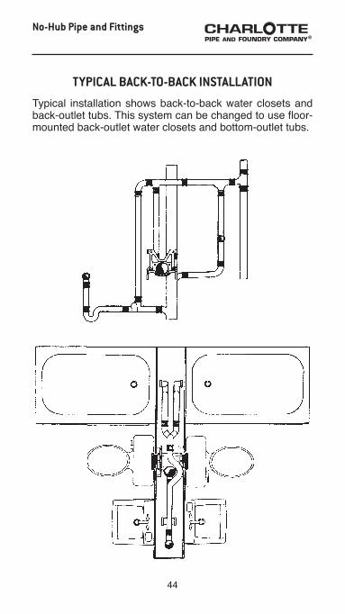
TYPICAL BACK-TO-BACK INSTALLATION
Typical installation shows back-to-back water closets and back-outlet tubs. This system can be changed to use floor-mounted back-outlet water closets and bottom-outlet tubs.
No-Hub Pipe and Fittings

45
Detail Drawings
PART NO. EZS 400D
Charlotte Pipe Starter Fitting4x30 Closet Fitting Double - M Inlet 0; B Inlet 61⁄2”
NO-HUB

46
Detail Drawings
PART NO. EZS 700D
Charlotte Pipe Starter Fitting4x28 Threaded Double - A Inlet 0; B Inlet 81⁄2”
with EZS 22 Support Frame and EZS 24 Trim Package

47
Detail Drawings
PART NO. EZS 700R
Charlotte Pipe Starter Fitting4x28 Threaded Right Hand - A Inlet 0; B Inlet 0
with EZS 23 Trim Package
DETAIL
DRAWINGS

48
Detail Drawings
PART NO. EZS 800D
Charlotte Pipe Starter Fitting4x28 Threaded Double - A Inlet 16; B Inlet 0
with EZS 23 Trim Package
49
Detail Drawings
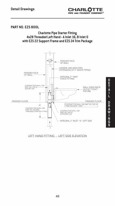
PART NO. EZS 800L
Charlotte Pipe Starter Fitting4x28 Threaded Left Hand - A Inlet 16; B Inlet 0
with EZS 22 Support Frame and EZS 24 Trim Package
DETAIL
DRAWINGS

50
Detail Drawings
PART NO. NH 458
Charlotte Pipe Starter Fitting4x4x2x2x4 Vented Closet Tee, Left Hand,
with 2” Top Vent and 2” Side Inlet

51
Detail Drawings
PART NO. NH 502
Charlotte Pipe Starter Fitting4” No-Hub with 2” Top Vent and 2” 45° Tap Service
for Two Cells at 45° Angle
DETAIL
DRAWINGS
52
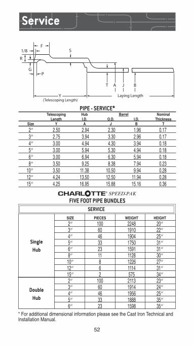
PIPE - SERVICE* Telescoping Hub Barrel Nominal Length I.D. O.D. I.D. Thickness Size Y A J B T
2” 2.50 2.94 2.30 1.96 0.17 3” 2.75 3.94 3.30 2.96 0.17 4” 3.00 4.94 4.30 3.94 0.18 5” 3.00 5.94 5.30 4.94 0.18 6” 3.00 6.94 6.30 5.94 0.18 8” 3.50 9.25 8.38 7.94 0.23 10” 3.50 11.38 10.50 9.94 0.28 12” 4.24 13.50 12.50 11.94 0.28 15” 4.25 16.95 15.88 15.16 0.36
Service
(Telescoping Length)Laying Length
BJAT
Y
PG
R
1/8 SF
* For additional dimensional information please see the Cast Iron Technical and Installation Manual.
SingleHub
Double Hub
FIVE FOOT PIPE BUNDLES
SIZE PIECES WEIGHT HEIGHT
2” 100 2248 20” 3” 60 1910 22” 4” 46 1904 25” 5” 33 1750 31” 6” 23 1591 31” 8” 11 1128 30” 10” 8 1226 27” 12” 6 1114 31” 15” 2 575 34” 2” 100 2113 23” 3” 60 1914 24” 4” 46 1956 25” 5” 33 1888 35” 6” 23 1598 35”
SERVICE
53
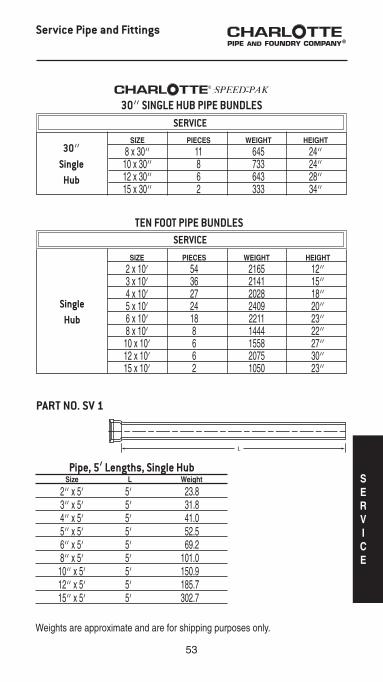
SIZE PIECES WEIGHT HEIGHT
2 x 10’ 54 2165 12” 3 x 10’ 36 2141 15” 4 x 10’ 27 2028 18” 5 x 10’ 24 2409 20” 6 x 10’ 18 2211 23” 8 x 10’ 8 1444 22” 10 x 10’ 6 1558 27” 12 x 10’ 6 2075 30” 15 x 10’ 2 1050 23”
SingleHub
SERVICE
Pipe, 5’ Lengths, Single Hub Size L Weight
2” x 5’ 5’ 23.8 3” x 5’ 5’ 31.8 4” x 5’ 5’ 41.0 5” x 5’ 5’ 52.5 6” x 5’ 5’ 69.2 8” x 5’ 5’ 101.0 10” x 5’ 5’ 150.9 12” x 5’ 5’ 185.7 15” x 5’ 5’ 302.7
PART NO. SV 1
Service Pipe and Fittings
SIZE PIECES WEIGHT HEIGHT
8 x 30” 11 645 24” 10 x 30” 8 733 24” 12 x 30” 6 643 28” 15 x 30” 2 333 34”
30”Single
Hub
30” SINGLE HUB PIPE BUNDLES
TEN FOOT PIPE BUNDLES
SERVICE
Weights are approximate and are for shipping purposes only.
SERVICE

54
Pipe, 5’ Lengths, Double Hub Size L Weight
2” x 5’ 4’ 91⁄2” 21.1 3” x 5’ 4’ 91⁄4” 31.9 4” x 5’ 4’ 9” 42.5 5” x 5’ 4’ 9” 57.2 6” x 5’ 4’ 9” 69.5
Pipe, 10’ Lengths, Single Hub Size L Weight
2” x 10’ 10’ 40.1 3” x 10’ 10’ 59.5 4” x 10’ 10’ 75.1 5” x 10’ 10’ 100.4 6” x 10’ 10’ 122.8 8” x 10’ 10’ 180.5 10” x 10’ 10’ 276.1 12” x 10’ 10’ 345.9 15” x 10’ 10’ 525.1
PART NO. SV 3
PART NO. SV 2
Service Pipe and Fittings
Pipe, 30” Lengths, Single Hub Size L Weight
8” x 30” 30” 58.7 10” x 30” 30” 91.7 12” x 30” 30” 107.1 15” x 30” 30” 166.3
PART NO. SV 1A

55
Service Pipe and Fittings
Pipe, 30” Lengths, Double Hub Size L Weight
2” x 30” 25” 13.8 3” x 30” 241⁄2” 17.6 4” x 30” 24” 27.1
PART NO. SV 4
PART NO. SV 900
Service Weight Charlotte Seal Gasket Size A D F G H Weight
2 31⁄2 23⁄16 21⁄8 31⁄8 131⁄32 0.3 3 41⁄2 33⁄16 31⁄8 41⁄8 21⁄16 0.4 4 51⁄2 43⁄16 41⁄8 51⁄4 29⁄32 0.5 5 61⁄2 53⁄16 51⁄8 61⁄4 29⁄32 0.6 6 71⁄2 63⁄16 61⁄8 71⁄4 21⁄4 0.8 8 93⁄4 813⁄32 83⁄16 99⁄32 3 1.5 10 127⁄16 101⁄2 105⁄16 1111⁄16 23⁄4 2.4
PART NO. SV 950
Service Weight Quik-Tite Gasket Size A D F G H Weight
2 31⁄2 21⁄16 2 31⁄4 13⁄32 0.3 3 47⁄8 31⁄16 31⁄16 43⁄8 13⁄4 0.4 4 53⁄4 4 4 53⁄16 13⁄4 0.5 5 63⁄4 5 5 6 21⁄16 0.8 6 8 65⁄16 65⁄16 711⁄32 25⁄32 0.8 8 10 83⁄16 83⁄16 81⁄2 21⁄2 1.5 10 121⁄4 101⁄4 10 111⁄2 21⁄2 2.3 12 143⁄8 121⁄4 12 14 27⁄8 3.0
GF
DA
H
H
GF
A
D
SERVICE
56
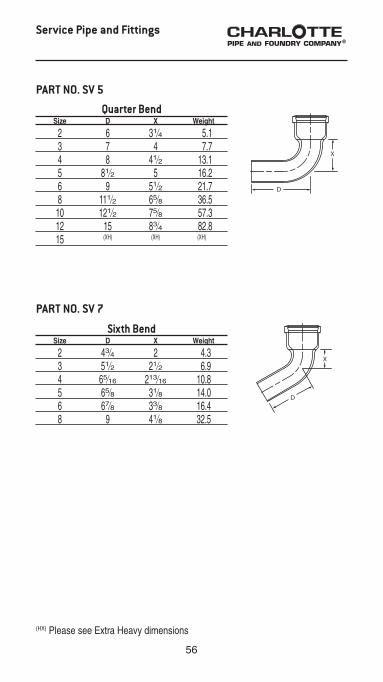
Sixth Bend Size D X Weight
2 43⁄4 2 4.3 3 51⁄2 21⁄2 6.9 4 65⁄16 213⁄16 10.8 5 65⁄8 31⁄8 14.0 6 67⁄8 33⁄8 16.4 8 9 41⁄8 32.5
PART NO. SV 7
Quarter Bend Size D X Weight
2 6 31⁄4 5.1 3 7 4 7.7 4 8 41⁄2 13.1 5 81⁄2 5 16.2 6 9 51⁄2 21.7 8 111⁄2 65⁄8 36.5 10 121⁄2 75⁄8 57.3 12 15 83⁄4 82.8 15 (XH) (XH) (XH)
PART NO. SV 5
(HX) Please see Extra Heavy dimensions
Service Pipe and Fittings

57
Eighth Bend Size D X Weight
2 41⁄4 11⁄2 4.2 3 415⁄16 115⁄16 6.5 4 511⁄16 23⁄16 10.7 5 57⁄8 23⁄8 13.1 6 61⁄16 29⁄16 16.6 8 8 31⁄8 32.3 10 83⁄8 31⁄2 44.1 12 105⁄16 41⁄16 65.4 15 (XH) (XH) (XH)
Sixteenth Bend Size D X Weight
2 35⁄8 7⁄8 3.4 3 43⁄16 13⁄16 6.0 4 413⁄16 15⁄16 8.8 5 47⁄8 13⁄8 11.6 6 5 11⁄2 13.8 8 611⁄16 113⁄16 24.6 10 67⁄8 2 37.1 12 85⁄8 23⁄8 57.7 15 (XH) (XH) (XH)
PART NO. SV 8
PART NO. SV 9
Service Pipe and Fittings
(HX) Please see Extra Heavy dimensions
SERVICE

58
Quarter Bend with Side Opening Size D X Weight
4w2LH 8 31⁄2 16.2 4w2RH 8 31⁄2 16.5
Double Quarter Bend Size D X Weight
4 8 41⁄2 15.0
PART NO. SV 12
PART NO. SV 15
Service Pipe and Fittings
Quarter Bend with Low Heel Inlet Size D X X’ Weight
3 x 2 7 4 9 9.8 4 x 2 8 41⁄2 101⁄2 13.0
PART NO. SV 10

59
Reducing Quarter Bend Size D X Weight
3 x 2 7 33⁄8 7.0 4 x 2 71⁄2 41⁄2 11.7 4 x 3 81⁄8 43⁄8 9.1
PART NO. SV 18
Service Pipe and Fittings
Long Quarter Bend Size D X Weight
2 x 12 12 31⁄4 6.9 3 x 12 12 4 10.3 4 x 12 12 41⁄2 15.4 4 x 16 16 41⁄2 20.4 4 x 18 18 41⁄2 21.4 4 x 24 24 41⁄2 27.9
PART NO. SV 25
Single Hub Return Bend Size D X J Weight
3 55⁄8 5 57⁄8 9.4 4 71⁄2 611⁄32 73⁄16 16.4
PART NO. SV 23
SERVICE

60
Long Eighth Bend Size D X Weight
2 x 12 12 11⁄2 6.2 3 x 12 12 115⁄16 9.9 3 x 18 18 115⁄16 12.4 4 x 12 12 23⁄16 15.6 4 x 18 18 23⁄16 20.6 6 x 18 18 29⁄16 31.0
PART NO. SV 26
Short Sweep Bend Size D X Weight
2 8 51⁄4 6.2 3 9 6 9.4 4 10 61⁄2 16.6 5 101⁄2 7 20.7 6 11 71⁄2 26.6 8 131⁄2 85⁄8 37.4 10 141⁄2 95⁄8 71.5 12 17 103⁄4 100.6
PART NO. SV 29
Service Pipe and Fittings

61
Long Sweep Bend Size D X Weight
2 11 81⁄4 7.6 3 12 9 12.2 4 13 91⁄2 21.2 5 131⁄2 10 25.3 6 14 101⁄2 29.9 8 161⁄2 115⁄8 52.9 10 171⁄2 125⁄8 82.6 12 20 133⁄4 103.5 15 (XH) (XH) (XH)
PART NO. SV 30
Service Pipe and Fittings
Reducing Long Sweep Bend Size D X Weight
3 x 2 12 9 12.0 4 x 3 13 91⁄2 17.6
PART NO. SV 31
Combination Wye & Eighth Bend (Charlotte Pattern)
Size G H X X’ Weight
4 57⁄16 43⁄8 113⁄8 61⁄2 20.3
PART NO. SV 32
(XH) Please see Extra Heavy dimensions
SERVICE

62
Combination Wye & Eighth Bend (Long Turn Pattern)
Size G H X X’ Weight
2 x 2 4 33⁄8 8 47⁄8 8.6 3 x 2 43⁄16 4 9 53⁄4 11.1 3 x 3 5 51⁄16 101⁄2 7 14.8 4 x 2 311⁄16 41⁄2 9 61⁄4 15.5 4 x 3 41⁄2 59⁄16 101⁄2 71⁄2 19.2 4 x 4 41⁄2 71⁄2 12 9 24.5 5 x 2 33⁄8 5 9 63⁄4 14.6 5 x 3 4 61⁄16 101⁄2 8 21.3 5 x 4 41⁄4 75⁄16 12 91⁄2 25.9 5 x 5 51⁄2 85⁄8 131⁄2 11 33.6 6 x 2 211⁄16 51⁄2 9 71⁄4 19.6 6 x 3 31⁄8 69⁄16 101⁄4 81⁄2 24.7 6 x 4 41⁄4 713⁄16 12 10 31.7 6 x 5 51⁄16 91⁄8 131⁄2 111⁄2 34.3 6 x 6 53⁄4 105⁄16 15 127⁄8 44.2 8 x 2 31⁄8 61⁄2 101⁄2 81⁄4 34.0 8 x 4 43⁄4 813⁄16 131⁄2 11 40.1 8 x 5 51⁄2 101⁄8 15 121⁄2 49.6 8 x 6 65⁄16 115⁄16 161⁄2 137⁄8 55.7 8 x 8 711⁄16 137⁄8 191⁄2 17 85.6
PART NO. SV 33
Service Pipe and Fittings
Double Combination Wye & Eighth Bend (Charlotte Pattern)
Size G H X X’ Weight
4 57⁄16 43⁄8 113⁄8 61⁄2 26.0
PART NO. SV 35

63
Double Combination Wye & Eighth Bend (Long Turn Pattern)
Size G H X X’ Weight
2 x 2 4 33⁄8 8 47⁄8 12.0 3 x 2 43⁄16 4 9 53⁄4 14.6 3 x 3 5 51⁄16 101⁄2 7 22.0 4 x 2 311⁄16 41⁄2 9 61⁄4 19.7 4 x 3 41⁄2 59⁄16 101⁄2 71⁄2 26.5 4 x 4 51⁄4 613⁄16 12 9 36.2 5 x 4 41⁄4 75⁄16 12 91⁄2 30.9 6 x 4 41⁄4 713⁄16 12 10 41.0 6 x 6 53⁄4 105⁄16 15 127⁄8 69.6
PART NO. SV 35F
Combination Wye & Eighth Bend with Side Inlet
Size G’ H X X’ Weight
4w/2RH 10 121⁄16 12 9 27.3 4w/2LH 10 121⁄16 12 9 28.3
PART NO. SV 39A
Service Pipe and Fittings
Combination Wye & Eighth Bend with Cleanout on Main
IPS Size Tap G X X’ Weight
4 31⁄2 9 123⁄16 121⁄4 18.9
PART NO. SV 41
Double Combination Wye & Eighth Bend with 2” Cup Hub Inlet
Size G G’ H X X’ Weight
4 41⁄4 10 613⁄16 12 9 41.7
PART NO. SV 35F
SERVICE

64
Straight Tee Size G X X’ Weight
2 x 2 61⁄4 8 13⁄4 7.0 3 x 2 7 9 21⁄2 9.0 3 x 3 71⁄2 10 21⁄2 12.0 4 x 2 7 9 3 12.7 4 x 3 71⁄2 10 3 14.0 4 x 4 8 11 3 16.6 5 x 5 81⁄2 12 31⁄2 19.0 6 x 4 8 11 4 19.9 6 x 6 9 13 4 24.0 8 x 4 95⁄8 127⁄8 51⁄4 37.0
PART NO. SV 42
Service Pipe and Fittings
65
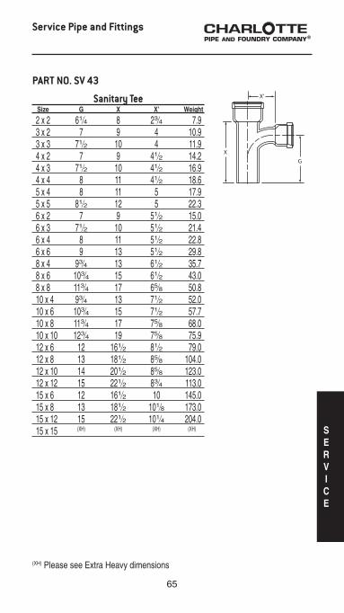
Sanitary Tee Size G X X’ Weight
2 x 2 61⁄4 8 23⁄4 7.9 3 x 2 7 9 4 10.9 3 x 3 71⁄2 10 4 11.9 4 x 2 7 9 41⁄2 14.2 4 x 3 71⁄2 10 41⁄2 16.9 4 x 4 8 11 41⁄2 18.6 5 x 4 8 11 5 17.9 5 x 5 81⁄2 12 5 22.3 6 x 2 7 9 51⁄2 15.0 6 x 3 71⁄2 10 51⁄2 21.4 6 x 4 8 11 51⁄2 22.8 6 x 6 9 13 51⁄2 29.8 8 x 4 93⁄4 13 61⁄2 35.7 8 x 6 103⁄4 15 61⁄2 43.0 8 x 8 113⁄4 17 65⁄8 50.8 10 x 4 93⁄4 13 71⁄2 52.0 10 x 6 103⁄4 15 71⁄2 57.7 10 x 8 113⁄4 17 75⁄8 68.0 10 x 10 123⁄4 19 75⁄8 75.9 12 x 6 12 161⁄2 81⁄2 79.0 12 x 8 13 181⁄2 85⁄8 104.0 12 x 10 14 201⁄2 85⁄8 123.0 12 x 12 15 221⁄2 83⁄4 113.0 15 x 6 12 161⁄2 10 145.0 15 x 8 13 181⁄2 101⁄8 173.0 15 x 12 15 221⁄2 101⁄4 204.0 15 x 15 (XH) (XH) (XH) (XH)
PART NO. SV 43
Service Pipe and Fittings
(XH) Please see Extra Heavy dimensions
SERVICE

66
Wye Size G X X’ Weight
2 x 2 4 8 4 8.3 3 x 2 43⁄16 9 5 10.9 3 x 3 5 101⁄2 51⁄2 12.2 4 x 2 35⁄8 9 53⁄4 14.4 4 x 3 47⁄16 101⁄2 61⁄4 16.8 4 x 4 51⁄4 12 63⁄4 20.3 5 x 2 31⁄8 9 61⁄2 15.3 5 x 3 37⁄8 101⁄2 7 19.8 5 x 4 411⁄16 12 71⁄2 23.0 5 x 5 51⁄2 131⁄2 8 27.0 6 x 2 29⁄16 9 71⁄4 19.7 6 x 3 33⁄8 101⁄2 73⁄4 23.7 6 x 4 43⁄16 12 81⁄4 26.7 6 x 5 415⁄16 131⁄2 83⁄4 29.5 6 x 6 53⁄4 15 91⁄4 36.5 8 x 2 31⁄8 101⁄2 81⁄2 31.0 8 x 3 315⁄16 12 9 33.2 8 x 4 43⁄4 131⁄2 91⁄2 38.3 8 x 5 51⁄2 15 10 41.2 8 x 6 65⁄16 161⁄2 101⁄2 45.4 8 x 8 711⁄16 191⁄2 1113⁄16 58.4 10 x 3 23⁄4 12 103⁄4 54.0 10 x 4 39⁄16 131⁄2 111⁄8 55.4 10 x 5 45⁄16 15 115⁄8 60.6 10 x 6 51⁄8 161⁄2 121⁄8 64.1 10 x 8 61⁄2 191⁄2 137⁄16 86.9 10 x 10 8 221⁄2 141⁄2 111.1 12 x 4 41⁄8 15 127⁄16 69.7 12 x 5 47⁄8 161⁄2 1215⁄16 78.0 12 x 6 511⁄16 18 137⁄16 87.7 12 x 8 71⁄16 21 143⁄4 100.6 12 x 10 89⁄16 24 1513⁄16 131.0 12 x 12 101⁄8 27 167⁄8 175.2 15 x 4 63⁄8 15 15 138.5 15 x 6 4 18 153⁄4 153.6 15 x 8 53⁄8 21 171⁄16 187.1 15 x 10 67⁄8 24 181⁄8 225.0 15 x 12 87⁄16 27 193⁄16 260.0 15 x 15 (XH) (XH) (XH) (XH)
PART NO. SV 44
Service Pipe and Fittings
(XH) Please see Extra Heavy dimensions

67
Sanitary Tee with Left Hand Side Tap
Size G G’ X X’ Weight
4w/2 8 9 11 41⁄2 16.3
PART NO. SV 50
Service Pipe and Fittings
Sanitary Tee with Right Hand Side Tap
Size G G’ X X’ Weight
4w/2 8 9 11 41⁄2 16.5
Sanitary Tee with Right and Left Hand Side Taps
Size G G’ X X’ Weight
4w/2 8 9 11 41⁄2 16.3
Sanitary Tee with Left Hand Side Inlet Size G G’ X X’ Weight
4w/2 8 9 11 41⁄2 20.2
PART NO. SV 50A
PART NO. SV 50B
PART NO. SV 56SERVICE

68
Sanitary Tee with Right and Left Hand Side Inlets
Size G G’ X X’ Weight
4w/2 8 9 11 41⁄2 23.1
Sanitary Tee with Right Hand Side Inlet
Size G G’ X X’ Weight
4w/2 8 9 11 41⁄2 20.0
PART NO. SV 56B
PART NO. SV 56C
Service Pipe and Fittings
Wye with Left Hand Side Inlet Size G G’ X X’ Weight
4w/2 51⁄4 10 12 63⁄4 23.8
Wye with Right Hand Side Inlet Size G G’ X X’ Weight
4w/2 51⁄4 10 12 63⁄4 23.8
PART NO. SV 57
PART NO. SV 57A

69
Short Special Two-Way Cleanout Size G X X’ Weight
4 8 12 4 16.0
Single Two-Way Cleanout Size X E’ G Weight
4 227⁄16 93⁄8 123⁄4 33.5
Double Two-Way Cleanout Size G J X X’ Weight
4 61⁄2 67⁄16 135⁄8 71⁄2 31.2 6 x 4 x 4 61⁄2 67⁄16 135⁄8 81⁄4 39.1
PART NO. SV 71A
PART NO. SV 71B
PART NO. SV 72
Service Pipe and Fittings
Sanitary Tee with Cleanout on Main IPS Size Tap G X X’ Weight
4 31⁄2 8 121⁄8 41⁄2 16.7
PART NO. SV 76
SERVICE

70
Miami Test Tee, Less Plug
Cleanout Tee with Brass Plug IPS Size Tap E’ G X Weight
2 11⁄2 2 61⁄4 8 6.2 3 2 21⁄2 7 9 9.3 4 3 3 8 11 14.6 5 4 31⁄2 81⁄2 12 18.7 6 4 41⁄4 9 13 25.3 12 8 8 13 181⁄2 92.2
Washington Test Tee¥ IPS Size Tap E’ G X Weight
2 2 13⁄4 7 9 7.3 3 4 27⁄8 71⁄8 103⁄4 13.1 4 4 31⁄4 71⁄4 105⁄8 16.8 5 5 35⁄8 7 11 22.5 6 6 4 83⁄4 13 26.9 8 8 5 11 163⁄8 41.6 10 10 71⁄2 11 175⁄8 68.7
PART NO. SV 79
PART NO. SV 80
PART NO. SV 81
Service Pipe and Fittings
¥ This fitting can be ordered without or with a Southern Raised Head Brass Plug installed (2” through 8” available with plug).
Miami Test Tee with SouthernRaised-Head Brass Plug Installed
IPS Size Tap E’ G X Weight
2 2 21⁄32 61⁄2 9 7.0 3 3 21⁄2 65⁄8 95⁄8 10.0 4 4 3 71⁄4 11 15.5 6 6 4 9 131⁄4 22.8
and PART NO. SV 81S

71
PART NO. SV 82
Test Tee with Internal Tap Size E’ G X Weight
4 215⁄16 77⁄8 12 15.9
Service Pipe and Fittings
Straight Tapped Tee Size E’ G X Weight
2 x 11⁄2 2 61⁄4 8 5.5 2 x 2 2 61⁄4 8 6.0 3 x 11⁄2 21⁄2 7 9 7.4 3 x 2 21⁄2 7 9 8.6 4 x 2 3 7 9 12.3 4 x 3 4 8 11 14.0 4 x 4 3 71⁄4 11 15.0 5 x 2 31⁄2 7 9 13.5 5 x 4 31⁄2 81⁄2 12 17.9 6 x 4 41⁄4 9 13 24.4
Sanitary Tapped Tee Size E’ G X Weight
2 x 11⁄2 213⁄16 61⁄4 8 6.0 2 x 2 31⁄16 61⁄4 8 5.8 3 x 11⁄2 35⁄16 7 9 8.0 3 x 2 39⁄16 7 9 8.1 4 x 11⁄2 313⁄16 7 9 10.3 4 x 2 41⁄16 7 9 11.7 4 x 3 41⁄16 8 11 13.6
PART NO. SV 83
PART NO. SV 84
SERVICE

72
Long Sanitary Tapped Tee Size E’ G X Weight
2 x 2 x 18 31⁄16 16 18 8.8
Tapped Wye Size G X X’ Weight
3 x 2 5 101⁄2 65⁄8 10.3 4 x 11⁄2 41⁄2 9 61⁄2 11.0 4 x 2 41⁄4 9 6 12.7
PART NO. SV 85
PART NO. SV 89
Service Pipe and Fittings
Sanitary Tapped Cross Size E’ G X Weight
2 x 11⁄2 213⁄16 61⁄4 8 11.3 2 x 2 31⁄16 61⁄4 8 6.7 3 x 2 39⁄16 7 9 9.0 4 x 2 41⁄16 7 9 11.6
Tapped Double Wye Size G X X’ Weight
4 x 2 53⁄4 12 77⁄8 16.9
PART NO. SV 91
PART NO. SV 92

73
Tapped Cross Size E’ G X Weight
3 x 2 21⁄2 7 9 9.4 4 x 2 3 7 9 13.1
PART NO. SV 93
Service Pipe and Fittings
Sanitary Cross Size G X X’ Weight
2 61⁄4 8 23⁄4 10.0 3 x 2 7 9 4 12.5 3 71⁄2 10 4 15.6 4 x 2 7 9 41⁄2 16.0 4 x 3 71⁄2 10 41⁄2 20.0 4 8 11 41⁄2 22.9 5 x 4 8 11 5 23.2 6 x 4 8 11 51⁄2 29.0 6 9 13 51⁄2 34.9 8 113⁄4 17 65⁄8 105.0
PART NO. SV 109
Straight Cross Size G X X’ Weight
4 x 2 7 9 3 16.0 4 8 11 3 17.0
PART NO. SV 108
SERVICE
74
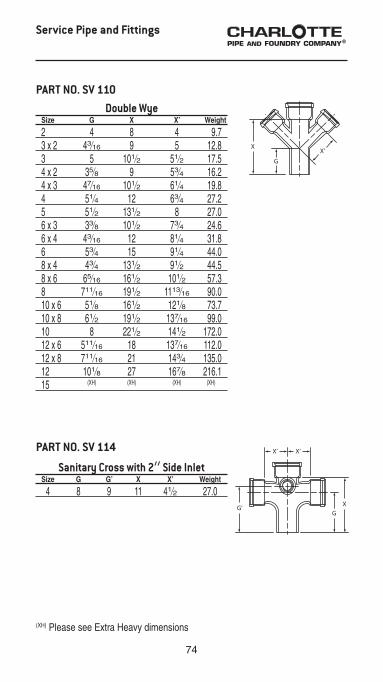
Double Wye Size G X X’ Weight
2 4 8 4 9.7 3 x 2 43⁄16 9 5 12.8 3 5 101⁄2 51⁄2 17.5 4 x 2 35⁄8 9 53⁄4 16.2 4 x 3 47⁄16 101⁄2 61⁄4 19.8 4 51⁄4 12 63⁄4 27.2 5 51⁄2 131⁄2 8 27.0 6 x 3 33⁄8 101⁄2 73⁄4 24.6 6 x 4 43⁄16 12 81⁄4 31.8 6 53⁄4 15 91⁄4 44.0 8 x 4 43⁄4 131⁄2 91⁄2 44.5 8 x 6 65⁄16 161⁄2 101⁄2 57.3 8 711⁄16 191⁄2 1113⁄16 90.0 10 x 6 51⁄8 161⁄2 121⁄8 73.7 10 x 8 61⁄2 191⁄2 137⁄16 99.0 10 8 221⁄2 141⁄2 172.0 12 x 6 511⁄16 18 137⁄16 112.0 12 x 8 711⁄16 21 143⁄4 135.0 12 101⁄8 27 167⁄8 216.1 15 (XH) (XH) (XH) (XH)
PART NO. SV 110
Service Pipe and Fittings
Sanitary Cross with 2” Side Inlet Size G G’ X X’ Weight
4 8 9 11 41⁄2 27.0
PART NO. SV 114
(XH) Please see Extra Heavy dimensions

75
“H” Branch Size X X’ J G Weight
4 x 3 123⁄16 79⁄16 6 41⁄2 17.0 4 1315⁄16 811⁄16 61⁄2 51⁄4 19.6
Double Wye with 2” Side Opening Size G H X X’ Weight
4 x 4 51⁄4 10 12 63⁄4 31.8
PART NO. SV 115
PART NO. SV 135
Service Pipe and Fittings
Bar Grate with Legs Size G X Weight
4 3 43⁄4 2.0
45° Offset Size/Offset X G’ J Weight
4 x 4 11 4 4 11.6 4 x 6 13 4 6 15.0 4 x 8 15 4 8 15.6
PART NO. SV 137
PART NO. SV 141
Vent BranchSize X X’ J G G’ Weight
4 11 6 61⁄2 4 8 19.6
PART NO. SV 134
SERVICE

76
Reducer Size X Weight
3 x 2 43⁄4 4.6 4 x 2 5 6.0 4 x 3 5 7.0 5 x 2 5 6.6 5 x 3 5 6.8 5 x 4 5 9.0 6 x 2 5 8.2 6 x 3 5 9.9 6 x 4 5 10.4 6 x 5 5 10.9 8 x 3 6 14.3 8 x 4 6 16.6 8 x 5 6 16.4 8 x 6 6 16.8 10 x 4 6 20.0 10 x 5 6 23.9 10 x 6 6 24.0 10 x 8 6 26.5 12 x 4 61⁄2 32.2 12 x 6 61⁄2 34.4 12 x 8 61⁄2 37.2 12 x 10 61⁄2 38.4 15 x 6 61⁄2 52.3 15 x 8 61⁄2 55.0 15 x 10 61⁄2 55.7 15 x 12 61⁄2 64.9
PART NO. SV 143
Service Pipe and Fittings
Reducer Increaser Size X Weight
2 x 4 9 9.4 3 x 4 9 8.8 4 x 5 9 11.3 4 x 6 9 15.2 4 x 8 12 24.5 5 x 6 9 12.8 6 x 8 12 24.0 8 x 10 12 44.0
PART NO. SV 144

77
Long Tapped Increaser Size X Weight
2 x 4 x 30 30 22.8
Long Plain Increaser Size X Weight
3 x 4 x 24 24 13.6 4 x 5 x 30 30 27.4
PART NO. SV 147
PART NO. SV 148
Service Pipe and Fittings
Tapped Spigot Size A Weight
4 x 2 41⁄4 4.7
PART NO. SV 151
SERVICE

78
Vent Cap with Set Screw Size Weight
4 2.6
Pipe Plug Size X Weight
2 31⁄2 1.3 3 33⁄4 2.5 4 4 4.1 5 4 6.0 6 4 8.0 8 41⁄2 12.4 10 41⁄2 17.7 12 51⁄4 23.3 15 (XH) (XH)
Double Hub Fitting Size X Weight
2 11⁄4 4.2 3 11⁄4 7.0 4 11⁄2 9.1 6 11⁄2 13.1 8 11⁄2 22.1 10 11⁄2 36.3 12 11⁄2 46.3 15 (XH) (XH)
PART NO. SV 153
PART NO. SV 155
PART NO. SV 159
Service Pipe and Fittings
“P” Trap Size J X Weight
2 4 91⁄2 7.1 3 51⁄2 12 13.1 4 61⁄2 14 23.2 5 71⁄2 151⁄2 30.4 6 81⁄2 17 42.0 8 101⁄2 221⁄16 86.2
PART NO. SV 169
(XH) Please see Extra Heavy dimensions

79
Service Pipe and Fittings
Running Trap Size X C J Weight
4 171⁄2 6 61⁄2 19.3 6 211⁄2 8 81⁄2 48.0
Running Trap with Single Hub Vent Vent Size Size C J X X’ Weight
3 3 5 51⁄2 15 21⁄2 15.3 4 4 6 61⁄2 171⁄2 3 28.3 5 4 7 71⁄2 191⁄2 31⁄2 39.7 6 4 8 81⁄2 211⁄2 4 45.9 8 4 10 11 275⁄8 51⁄4 95.9 8 6 10 11 275⁄8 51⁄4 110.0
PART NO. SV 170
PART NO. SV 174
Running Trap with Double Hub Vent
Vent Size Size C J X X’ Weight
3 3 5 51⁄2 15 21⁄2 23.0 4 4 6 61⁄2 171⁄2 3 36.3 5 4 7 71⁄2 191⁄2 31⁄2 42.5 6 4 8 81⁄2 211⁄2 4 57.3 6 6 8 81⁄2 211⁄2 4 61.5 8 4 10 11 275⁄8 51⁄4 98.8 8 6 10 11 275⁄8 51⁄4 99.7 10 8 12 13 315⁄8 61⁄4 187.0 12 10 15 15 383⁄4 71⁄4 287.6 15 12 181⁄2 181⁄2 45 9 460.0
PART NO. SV 175
SERVICE

80
Service Pipe and Fittings
Deep Seal “P” Trap Size X J Weight
2 91⁄2 6 8.1 3 12 7 14.3 4 14 8 29.0 6 17 91⁄2 40.4
“P” Trap with Cleanout Right Side Size X J B D Weight
4 14 61⁄2 11 51⁄2 20.0
Improved Running Trap with Double Cleanout and Tee Branch
Vent Size Size E G X X’ Weight
4 3 51⁄4 61⁄4 201⁄2 51⁄2 34.3 4 4 53⁄8 61⁄4 201⁄2 51⁄2 33.7
PART NO. SV 180
PART NO. SV 184(T)
PART NO. SV 188(T)
“P” Trap with 1⁄2” Heel Tap Size X J A Weight
2 91⁄2 4 4 6.8 3 12 51⁄2 43⁄8 13.0 4 14 61⁄2 45⁄8 23.1
PART NO. SV 198
“P” Trap with Cleanout Left Side Size X J B D Weight
4 14 61⁄2 11 51⁄2 20.0
PART NO. SV 188A(T)
(T) Note: 31⁄2” IPS tap

81
Service Pipe and Fittings
PART NO. SV 200
Closet Bend, Plain - Less Collar Size A B Weight
3 x 4 6 12 11.3 3 x 4 6 15 12.0 3 x 4 6 16 12.0 3 x 4 6 18 13.0 3 x 4 8 18 14.0 3 x 4 10 12 13.0 3 x 4 10 15 13.0 3 x 4 10 16 17.5 3 x 4 10 18 16.0 3 x 4 12 12 15.9 3 x 4 16 16 20.6 3 x 4 18 18 22.7 3 16 16 16.7 4 4 12 12.3 4 4 14 11.0 4 4 16 14.3 4 4 18 17.1 4 6 12 12.5 4 6 15 15.0 4 6 16 16.9 4 6 18 14.0 4 8 16 18.4 4 8 18 19.8 4 10 12 15.3 4 10 15 18.0 4 10 16 19.6 4 10 18 19.0 4 12 12 14.0 4 12 14 14.0 4 12 16 20.8 4 12 18 19.0 4 14 16 22.6 4 14 18 24.0 4 16 16 23.8 4 16 18 24.7 4 18 18 27.4
SERVICE

82
Service Pipe and Fittings
Hub-End Closet Bend, Low Hub Size A B Weight
4 45⁄8 12 14.2 4 45⁄8 14 15.4 4 45⁄8 16 17.5 4 45⁄8 18 18.9
PART NO. SV 208
Greensboro Reducing Closet Flange
(Can be used to connect 4” fixture with 3” line, or 4” No-Hub)
Size A B Weight
4 x 3 x 3 31⁄8 73⁄16 3.7
PART NO. SPL 219
Offset Closet Flange (To Offset 1”) Size A B C D Weight
4 x 2 2 6 1 5⁄8 2.5 4 x 21⁄2 21⁄2 73⁄16 1 5⁄8 3.3 4 x 4◊ 4 61⁄4 2 2 4.5
PART NO. SPL 217
PART NO. SV 206
Tapped Closet Bend withSouthern Code Brass Plug
Size A B Weight
31⁄2 x 4 x 4 x 18 18 4 17.4
◊ 2” Offset

83
Service Pipe and Fittings
Closet Flange, Notched and Slotted Size A B Weight
4 x 1 1 73⁄16 2.0 4 x 11⁄2 11⁄2 73⁄16 2.6 4 x 2 2 73⁄16 3.0 4 x 21⁄2 21⁄2 73⁄16 3.6 4 x 3 3 73⁄16 4.3 4 x 4 4 73⁄16 4.7 4 x 5 5 73⁄16 4.5 4 x 6 6 73⁄16 5.3
PART NO. SPL 220*
Instant Set Closet Flange Size A Weight
3 x 2† 2 3.5 4 x 2‡ 2 5.6 4 x 3§ 2 3.0 4 x 4‡ 4 4.0
PART NO. SPL 225
* Caulk type to go over pipe.† Four-bolt pattern. Test cap configuration not offered.‡ Three-bolt pattern. Available with or without test cap.§ Three-bolt reducing pattern, with test cap.
SERVICE

84
Service Pipe and Fittings
PART NO. SV 458Vented Closet Tee with 2” Top Vent
and 2” Extended Side Inlet (Right Hand or Left Hand; Designed for use
below the floor; Fitting does not require a baffle) Size A B C D E Weight
4x4x2x2x4 RH 11 41⁄2 53⁄16 49⁄16 43⁄16 37.0 4x4x2x2x4 LH 11 41⁄2 53⁄16 49⁄16 43⁄16 37.8
Sission Insertable Joint Size A B C Weight
2 14 6 6 7.0 3 16 8 63⁄4 11.6 4 141⁄2 7 6 12.9 5 157⁄8 9 57⁄8 17.0 6 163⁄16 81⁄2 6 20.4 8 18 10 63⁄4 37.0
PART NO. SV 253
Iron Body Cleanout Ferrule, Body Only, Less Brass Plug
PART NO. SV 228
(XH) Please see Extra Heavy dimensions.¥ This fitting not available with plug installed in 4 x 31⁄2 and 4 x 8 fitting sizes.
Iron Body Cleanout Ferrule with SouthernRaised-Head Brass Plug Installed ¥
Size Tap Size A Weight
2 11⁄2 31⁄2 1.3 3 21⁄2 33⁄4 2.0 4 3 41⁄4 3.6 5 4 41⁄4 4.5 6 5 41⁄4 5.2 8 6 41⁄2 11.7 10 6 41⁄2 16.3 12 6 51⁄4 25.5 15 (XH) (XH) (XH)
4 x 31⁄2 31⁄2 41⁄2 4.0 4 x 8 31⁄2 8 8.1 4 x 12 31⁄2 12 9.2
and PART NO. SV 228S

85
Service Pipe and Fittings
PART NO. SV 460
Vented Closet Tee with 2” Top Vent (Right Hand or Left Hand; Designed for use
below the floor; Fitting does not require a baffle) Size A B C Weight
4 x 4 x 2 x 4 RH 11 41⁄2 53⁄16 35.0 4 x 4 x 2 x 4 LH 11 41⁄2 53⁄16 35.0
PART NO. SV 459D
Vented Closet Cross with 2” Top Ventand 2” Extended Side Inlet
(Designed for use below the floor; Fitting does not have a baffle)
Size A B C Weight
4 x 4 x 2 x 2 x 4 11 61⁄4 43⁄4 47.0
PART NO. SV 566
Tapped Long Sweep Tee Size A B C D Weight
2 x 2 51⁄2 31⁄8 4 55⁄8 6.2
PART NO. SV 463D
Vented Closet Cross with 2” Top Vent and 2" Extended Side Inlet
(Designed for use below the floor; Fitting does not have a baffle)
Size A B C Weight
4 x 4 x 2 11 61⁄4 43⁄4 43.8 SERVICE

86
PART NO. SV 581Double Sink Stack-1770
(Designed for use above the floor) Size A B C D E Weight
3 x 2 x 2 123⁄4 41⁄2 65⁄8 41⁄2 53⁄4 18.0 4 x 2 x 2 121⁄2 5 71⁄2 41⁄2 65⁄8 21.4
Service Pipe and Fittings
3 x 2 x 2 Fitting
4 x 2 x 2 Fitting

87
Service Pipe and Fittings
SERVICE
PART NO. SV 581 B
Double Sink Stack with Baffle(Designed for use above the floor)
Size A B C D E Weight
4 x 2 x 2 121⁄2 5 71⁄2 41⁄2 65⁄8 23.8

88
NOTES:1. Single Vertical R.H. Offset Back Outlet Starter Fitting2. 4”Stack with 2”Vent & Inlets3. Face Plate Package Not Included
PART NO. SV 973R
Right Hand Starter Fitting with 4” Tap and 2” Tapped “A” Side Inlet(Designed for use above the floor with back-outlet water closets)
Size Inlet A B C D E F X Weight
4 61⁄2 See Chart 61⁄2 4 41⁄16 4 4 25 34.8 4 91⁄2 See Chart 61⁄2 4 41⁄16 4 4 25 34.4
Service Pipe and Fittings
INLETA
6 1⁄29 1⁄2

89
NOTES:1. Single Vertical L.H. Offset Back Outlet Starter Fitting2. 4”Stack with 2”Vent & Inlets3. Face Plate Package Not Included
PART NO. SV 973L
Left Hand Starter Fitting with 4” Tap and 2” Tapped“A” Side Inlet(Designed for use above the floor with back-outlet water closets)
Size Inlet A B C D E F X Weight
4 61⁄2 See Chart 61⁄2 4 4 4 4 25 39.2 4 91⁄2 See Chart 61⁄2 4 4 4 4 25 39.0
Service Pipe and Fittings
INLETA
6 1⁄29 1⁄2
SERVICE

90
PART NO. SV 974R
Right Hand Starter Fitting with 4” Hub and 2” Tapped “A” Side Inlet
(Designed for use above or in the floor with back-outlet or bottom-outlet water closets)
Size A B C D E F X Weight
4 with A Inlet 61⁄2 61⁄2 61⁄2 41⁄16 4 4 25 39.2
Service Pipe and Fittings
INLETA
6 1⁄2
91
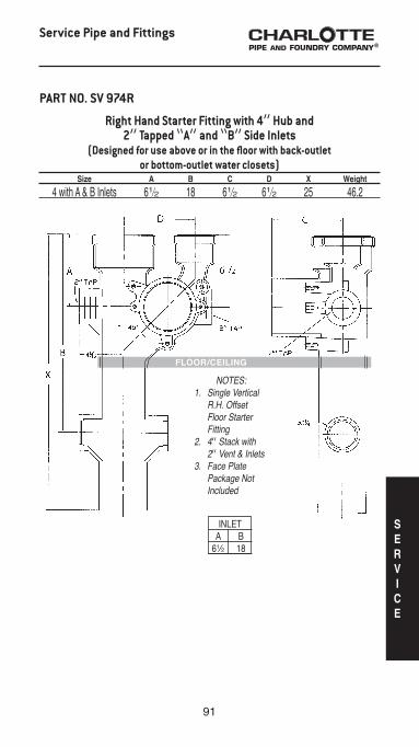
INLET A B 61⁄2 18
Right Hand Starter Fitting with 4” Hub and 2” Tapped “A” and “B” Side Inlets
(Designed for use above or in the floor with back-outlet or bottom-outlet water closets)
Size A B C D X Weight
4 with A & B Inlets 61⁄2 18 61⁄2 61⁄2 25 46.2
Service Pipe and Fittings
PART NO. SV 974R
NOTES:1. Single Vertical R.H. Offset Floor Starter Fitting2. 4” Stack with 2” Vent & Inlets3. Face Plate Package Not Included
FLOOR/CEILING
SERVICE

92
PART NO. SV 974L
Service Pipe and Fittings
Left Hand Starter Fitting with 4” Hub and 2” Tapped “A” Side Inlet
(Designed for use above or in the floor with back-outlet or bottom-outlet water closets)
Size A B C D E F X Weight
4 with A Inlet 61⁄2 61⁄2 61⁄2 4 4 41⁄16 25 39.7
INLETA
6 1⁄2

93
NOTES:1. Single Vertical L.H. Offset Floor Starter Fitting2. 4” Stack with 2” Vent & Inlets3. Face Plate Package Not Included
INLET A B 61⁄2 18
Service Pipe and Fittings
Left Hand Starter Fitting with 4” Hub and 2” Tapped “A” and “B” Side Inlets
(Designed for use above or in the floor with back-outlet or bottom-outlet water closets)
Size A B C D X Weight
4 with A & B Inlets 61⁄2 18 61⁄2 61⁄2 25 43.7
PART NO. SV 974L
FLOOR/CEILING
SERVICE

94
NOTES:1. Double Vertical Offset Back Outlet Starter Fitting2. 4”Stack with 2” Vent & Inlets3. Face Plate Package Not Included
PART NO. SV 975
Service Pipe and Fittings
INLETA
9 1⁄2
Double Starter Fitting with 4” Tap and2” Tapped “A” Side Inlet
(Designed for use above the floor with back-outlet water closets; Fitting has a baffle)
Size A B C D E F X Weight
4 with A Inlet 91⁄2 61⁄2 4 4 4 41⁄16 25 42.5

95
PART NO. SV 976
Service Pipe and Fittings
INLETA
6 1⁄2
Double Starter Fitting with 4” Hub and 2” Tapped “A” Side Inlet (Designed for use above or in the floor with back-outlet
or bottom-outlet water closets; Fitting has a baffle) Size A B C D E F X Weight
4 with A Inlet 61⁄2 61⁄2 61⁄2 4 4 41⁄16 25 50.8
SERVICE

96
Service Pipe and Fittings
INLET A B 61⁄2 18
Double Starter Fitting with 4” Hub and 2” Tapped “A” and “B” Side Inlets
(Designed for use above or in the floor with back-outlet or bottom-outlet water closets; Fitting has a baffle)
Size A B C D E X Weight
4 with A & B Inlets 61⁄2 18 61⁄2 61⁄2 41⁄16 25 56.6
PART NO. SV 976
NOTES:1. Double Vertical Offset Floor Outlet Starter Fitting2. 4” Stack with 2” Vent & Inlets3. Face Plate Package Not Included
FLOOR/CEILING

97
PART NO. SV 982
Tapped By-Pass Vent Fitting Size A B C D E F Weight
2 x 2 18 10 61⁄2 31⁄2 3 51⁄4 11.3
Service Pipe and Fittings
PART NO. SV 985
Tapped Bath Vent Wye Size A B C D Weight
2 x 2 41⁄16 5 31⁄4 21⁄2 8.4
SERVICE

98
PART NO. SV 1739R
Right Hand Vented Closet Tee with 2” 45° Taps(Designed for use above the floor)
Size A B C D E F G Weight
4 x 2 x 4 x 2 18 63⁄4 81⁄4 45⁄8 35⁄8 41⁄2 23⁄4 51.1
Service Pipe and Fittings

99
PART NO. SV 1739L
Service Pipe and Fittings
Left Hand Vented Closet Tee with 2” 45° Taps (Designed for use above the floor)
Size A B C D E F G Weight
4 x 2 x 4 x 2 18 63⁄4 81⁄4 45⁄8 35⁄8 41⁄2 23⁄4 51.0
SERVICE

100
PART NO. SV 1739 D
Service Pipe and Fittings
Vented Closet Cross with 2” 45° Taps(Designed for use above the floor)
Size A B C D E F G Weight
4 x 2 x 4 x 2 18 63⁄4 81⁄4 45⁄8 35⁄8 41⁄2 23⁄4 57.5

101
PART NO. SV 1801
Tapped Harp Fitting Size A B C Weight
2 x 2 x 2 117⁄16 2 35⁄8 15.5
Service Pipe and Fittings
SERVICE

102
➀ SV 1739 Left Hand Vented Closet Tee with 2” 45° Taps ➁ SV 1801 2x2x2 Tapped Harp Fitting ③ SV 83 5x2 Straight Tapped Tee ④ 5x10 SV Single Hub Pipe ➄ 4x10 SV Single Hub Pipe SV 206 4x4x18 Tapped Closet Bend with Southern Code Brass Plug
Service Pipe and Fittings
MULTI-STORY INSTALLATION

103
➀ SV 581 4x2x2 Double Sink Stack — 1770 ➁ SV 83 3x2 Straight Tapped Tee ③ 3x10 Single Hub Pipe ④ 4x10 Single Hub Pipe
Service Pipe and Fittings
MULTI-STORY INSTALLATION
SERVICE

104
Extra Heavy
PIPE - EXTRA-HEAVY* Telescoping Hub Barrel Nominal Length I.D. O.D. I.D. Thickness Size Y A J B T
2” 2.50 3.06 2.38 2.00 0.19 3” 2.75 4.19 3.50 3.00 0.25 4” 3.00 5.19 4.50 4.00 0.25 5” 3.00 6.19 5.50 5.00 0.25 6” 3.00 7.19 6.50 6.00 0.25 8” 3.50 9.50 8.62 8.00 0.31 10” 3.50 11.62 10.75 10.00 0.37 12” 4.25 13.75 12.75 12.00 0.37 15” 4.25 16.95 15.88 15.00 0.44
(Telescoping Length)Laying Length
BJAT
Y
PG
R
1/8 SF
* For additional dimensional information please see the Cast Iron Technical and Installation Manual.
SingleHub
Double Hub
FIVE FOOT PIPE BUNDLES EXTRA HEAVY WEIGHT
SIZE PIECES WEIGHT HEIGHT
2” 84 2099 18” 3” 45 1998 20” 4” 33 1968 21” 5” 23 1695 25” 6” 18 1465 23” 8” 11 1552 24” 10” 8 1574 29” 12” 6 1471 29” 15” 2 700 20” 2” 84 2207 23” 3” 45 2007 24” 4” 33 1992 25” 5” 23 1847 29” 6” 18 1535 28”

105
Extra Heavy Pipe and Fittings
Pipe, 5’ Lengths, Single Hub Size L Weight
2” x 5’ 5’ 25.0 3” x 5’ 5’ 44.4 4” x 5’ 5’ 59.6 5” x 5’ 5’ 73.7 6” x 5’ 5’ 81.4 8” x 5’ 5’ 141.1 10” x 5’ 5’ 196.7 12” x 5’ 5’ 245.2 15” x 5’ 5’ 350.0
PART NO. XH 1
SingleHub
EXTRA HEAVY WEIGHT
30”Single
Hub
30” SINGLE HUB PIPE BUNDLES
TEN FOOT PIPE BUNDLES
EXTRA HEAVY WEIGHT
Weights are approximate and are for shipping purposes only.
SIZE PIECES WEIGHT HEIGHT
2 x 10’ 48 2173 12” 3 x 10’ 30 2517 15” 4 x 10’ 24 2517 18” 5 x 10’ 21 2820 20” 6 x 10’ 12 1879 16” 8 x 10’ 8 1968 21” 10 x 10’ 6 2252 25” 12 x 10’ 3 1413 15” 15 x 10’ 2 1353 20”
SIZE PIECES WEIGHT HEIGHT
8 x 30” 11 835 26” 10 x 30” 8 901 24” 12 x 30” 6 816 30” 15 x 30” 2 394 19”
EXTRA
HEAVY

106
Pipe, 30” Lengths, Single Hub Size L Weight
8” x 30” 30” 75.9 10” x 30” 30” 112.6 12” x 30” 30” 136.0 15” x 30” 30” 197.0
PART NO. XH 1A
Extra Heavy Pipe and Fittings
Pipe, 5’ Lengths, Double Hub Size L Weight
2” x 5’ 4’ 91⁄2” 26.3 3” x 5’ 4’ 91⁄4” 44.6 4” x 5’ 4’ 9” 60.4 5” x 5’ 4’ 9” 80.3 6” x 5’ 4’ 9” 85.3
PART NO. XH 2
Pipe, 10’ Lengths, Single Hub Size L Weight
2” x 10’ 10’ 45.3 3” x 10’ 10’ 83.9 4” x 10’ 10’ 104.9 5” x 10’ 10’ 134.3 6” x 10’ 10’ 156.6 8” x 10’ 10’ 246.1 10” x 10’ 10’ 375.4 12” x 10’ 10’ 471.0 15” x 10’ 10’ 676.4
PART NO. XH 3

107
Extra Heavy Pipe and Fittings
Pipe, 30” Lengths, Double Hub Size L Weight
2” x 30” 25” 15.0 3” x 30” 241⁄2” 26.0 4” x 30” 24” 33.0
PART NO. XH 4
PART NO. XH 900
Extra Heavy Charlotte Seal Gasket Size A D F G H Weight
2 31⁄2 23⁄8 29⁄32 33⁄16 17⁄8 0.3 3 415⁄16 31⁄2 31⁄2 41⁄2 21⁄4 0.4 4 53⁄4 47⁄32 413⁄32 57⁄16 21⁄4 0.6 5 63⁄4 51⁄2 51⁄2 63⁄16 21⁄2 0.7 6 8 61⁄2 61⁄2 73⁄8 21⁄2 0.9 8 10 81⁄2 85⁄16 91⁄2 3 1.6 10 121⁄2 103⁄4 1011⁄32 111⁄2 3 2.0 12 147⁄16 125⁄8 125⁄8 14 3 2.8
PART NO. XH 950
Extra Heavy Quick-Tite Gasket Size A D F G H Weight
4 61⁄8 41⁄4 413⁄32 511⁄16 113⁄16 0.6 15 173⁄4 1513⁄32 15 167⁄8 31⁄4 5.0
GF
DA
H
H
GF
A
D
EXTRA
HEAVY

108
Extra Heavy Pipe and Fittings
Quarter Bend Size D X Weight
2 6 31⁄4 6.3 3 7 4 11.1 4 8 41⁄2 15.5 5 81⁄2 5 18.5 6 9 51⁄2 25.8 8 111⁄2 65⁄8 47.0 10 121⁄2 75⁄8 80.0 12 15 83⁄4 142.0 15 161⁄2 101⁄4 173.9
PART NO. XH 5
Sixth Bend Size D X Weight
2 43⁄4 2 6.0 3 51⁄2 21⁄2 7.2 4 65⁄16 213⁄16 14.0 6 67⁄8 33⁄8 21.0
PART NO. XH 7

109
Extra Heavy Pipe and Fittings
Eighth Bend Size D X Weight
2 41⁄4 11⁄2 4.7 3 415⁄16 115⁄16 8.8 4 511⁄16 23⁄16 12.4 5 57⁄8 23⁄8 15.0 6 61⁄16 29⁄16 18.9 8 8 31⁄8 36.2 10 83⁄8 31⁄2 59.7 12 105⁄16 41⁄16 90.0 15 1015⁄16 411⁄16 122.0
Sixteenth Bend Size D X Weight
2 35⁄8 7⁄8 4.6 3 43⁄16 13⁄16 9.1 4 413⁄16 15⁄16 9.5 5 47⁄8 13⁄8 13.8 6 5 11⁄2 16.0 8 611⁄16 113⁄16 31.8 10 67⁄8 2 53.0 12 85⁄8 23⁄8 65.0 15 87⁄8 25⁄8 103.0
PART NO. XH 8
PART NO. XH 9
Long Eighth Bend Size D X Weight
4 x 18 18 23⁄16 26.0
PART NO. XH 26
EXTRA
HEAVY

110
Short Sweep Bend Size D X Weight
2 8 51⁄4 7.2 3 9 6 13.0 4 10 61⁄2 18.2 5 101⁄2 7 23.8 6 11 71⁄2 28.4 8 131⁄2 85⁄8 57.0 10 141⁄2 95⁄8 90.0 12 17 103⁄4 136.0
Long Sweep Bend Size D X Weight
2 11 81⁄4 9.0 3 12 9 16.6 4 13 91⁄2 23.6 5 131⁄2 10 30.0 6 14 101⁄2 38.2 8 161⁄2 115⁄8 58.6 10 171⁄2 125⁄8 109.0 12 20 133⁄4 136.0 15 211⁄2 151⁄4 213.3
PART NO. XH 29
PART NO. XH 30
Extra Heavy Pipe and Fittings

111
Extra Heavy Pipe and Fittings
Combination Wye & Eighth Bend (Long Turn Pattern)
Size G H X X’ Weight
2 x 2 4 33⁄8 8 47⁄8 9.7 3 x 2 43⁄16 4 9 53⁄4 16.0 3 x 3 5 51⁄16 101⁄2 7 18.2 4 x 2 311⁄16 41⁄2 9 61⁄4 18.9 4 x 3 41⁄2 59⁄16 101⁄2 71⁄2 22.0 4 x 4 41⁄2 71⁄2 12 9 28.1 5 x 4 41⁄4 75⁄16 12 91⁄2 29.3 5 x 5 51⁄2 85⁄8 131⁄2 11 33.7 6 x 2 211⁄16 51⁄2 9 71⁄4 22.0 6 x 3 31⁄8 69⁄16 101⁄2 81⁄2 30.4 6 x 4 41⁄4 713⁄16 12 10 38.5 6 x 6 53⁄4 105⁄16 15 127⁄8 53.5 8 x 4 43⁄4 813⁄16 131⁄2 11 54.0 8 x 6 65⁄16 115⁄16 161⁄2 137⁄8 70.5 8 x 8 711⁄16 137⁄8 191⁄2 17 107.4
PART NO. XH 33
Double Combination Wye & Eighth Bend (Long Turn Pattern)
Size G H X X’ Weight
4 x 4 51⁄4 613⁄16 12 9 44.0 6 x 4 41⁄4 713⁄16 12 10 43.0
PART NO. XH 35F
EXTRA
HEAVY

112
Extra Heavy Pipe and Fittings
Sanitary Tee Size G X X’ Weight
2 x 2 61⁄4 8 27⁄8 8.7 3 x 2 7 9 4 14.2 3 x 3 71⁄2 10 4 17.1 4 x 2 7 9 41⁄2 17.4 4 x 3 71⁄2 10 41⁄2 18.3 4 x 4 8 11 41⁄2 22.5 5 x 5 81⁄2 12 5 28.0 6 x 3 71⁄2 10 51⁄2 24.4 6 x 4 8 11 51⁄2 28.0 6 x 6 9 13 51⁄2 35.4 8 x 4 93⁄4 13 61⁄2 51.0 8 x 6 103⁄4 15 61⁄2 54.5 8 x 8 113⁄4 17 65⁄8 72.0 10 x 6 103⁄4 15 71⁄2 77.0 10 x 8 113⁄4 17 75⁄8 95.0 10 x 10 123⁄4 19 75⁄8 115.0 12 x 8 13 181⁄2 85⁄8 126.0 12 x 12 15 221⁄2 83⁄4 173.0 15 x 8 13 181⁄2 101⁄8 180.0 15 x 15 161⁄2 251⁄2 101⁄4 280.0
PART NO. XH 43

113
Extra Heavy Pipe and Fittings
Wye Size G X X’ Weight
2 x 2 4 8 4 9.0 3 x 2 43⁄16 9 5 13.2 3 x 3 5 101⁄2 51⁄2 17.2 4 x 2 35⁄8 9 53⁄4 16.8 4 x 3 47⁄16 101⁄2 61⁄4 20.6 4 x 4 51⁄4 12 63⁄4 23.7 5 x 3 37⁄8 101⁄2 7 23.7 5 x 4 411⁄16 12 71⁄2 28.3 5 x 5 51⁄2 131⁄2 8 31.6 6 x 3 33⁄8 101⁄2 73⁄4 26.8 6 x 4 43⁄16 12 81⁄4 31.9 6 x 5 415⁄16 131⁄2 83⁄4 33.8 6 x 6 53⁄4 15 91⁄4 41.2 8 x 4 43⁄4 131⁄2 91⁄2 50.2 8 x 6 65⁄16 161⁄2 101⁄2 61.5 8 x 8 711⁄16 191⁄2 1113⁄16 86.6 10 x 4 39⁄16 131⁄2 111⁄8 72.0 10 x 6 51⁄8 161⁄2 121⁄8 84.0 10 x 8 61⁄2 191⁄2 137⁄16 101.7 10 x 10 8 221⁄2 141⁄2 137.0 12 x 6 511⁄16 18 137⁄16 108.0 12 x 8 71⁄16 21 143⁄4 140.0 12 x 10 89⁄16 24 1513⁄16 180.0 12 x 12 101⁄8 27 167⁄8 198.0 15 x 4 67⁄8 15 15 153.0 15 x 8 53⁄8 21 171⁄16 219.0 15 x 10 67⁄8 24 181⁄8 229.0 15 x 12 87⁄16 27 193⁄16 236.0 15 x 15 103⁄4 311⁄2 203⁄4 309.4
PART NO. XH 44
EXTRA
HEAVY

114
Miami Test Tee IPS Size Tap E’ G X Weight
4 4 3 71⁄4 11 16.0
Cleanout Tee with Brass Plug IPS Size Tap E’ G X Weight
3 2 21⁄2 7 9 11.3 4 3 3 8 11 15.5 5 4 31⁄2 81⁄2 12 22.9 6 4 41⁄4 9 13 26.9
PART NO. XH 80
PART NO. XH 81S
Extra Heavy Pipe and Fittings
Washington Test Tee IPS Size Tap E’ G X Weight
3 4 27⁄8 71⁄8 103⁄4 13.9 4 4 31⁄4 71⁄4 105⁄8 19.9 5 5 35⁄8 7 11 24.4 6 6 4 83⁄4 13 42.2 8 8 5 11 163⁄8 58.5
PART NO. XH 79

115
Extra Heavy Pipe and Fittings
Sanitary Tapped Tee Size E’ G X Weight
4 x 2 41⁄16 7 9 14.3
PART NO. XH 84
Tapped Wye Size G X X’ Weight
4 x 2 41⁄4 9 6 13.8
PART NO. XH 85
Sanitary Cross Size G X X’ Weight
4 8 11 41⁄2 27.0
PART NO. XH 109
EXTRA
HEAVY

116
Extra Heavy Pipe and Fittings
Double Wye Size G X X’ Weight
2 4 8 4 13.1 4 x 3 47⁄16 101⁄2 61⁄4 26.9 4 51⁄4 12 63⁄4 28.2 6 x 4 43⁄16 12 81⁄4 39.8 6 53⁄4 15 91⁄4 45.0 8 711⁄16 191⁄2 1113⁄16 119.0 10 8 221⁄2 141⁄2 182.0 12 101⁄8 27 167⁄8 295.0 15 103⁄4 311⁄2 22 384.8
PART NO. XH 110
Reducer Size X Weight
3 x 2 43⁄4 6.0 4 x 2 5 7.0 4 x 3 5 8.9 5 x 3 5 11.0 5 x 4 5 11.0 6 x 3 5 12.0 6 x 4 5 12.2 6 x 5 5 12.6 8 x 4 6 19.1 8 x 5 6 19.5 8 x 6 6 19.0 10 x 4 6 28.0 10 x 6 6 30.0 10 x 8 6 35.0 12 x 4 61⁄2 36.8 12 x 6 61⁄2 46.0 12 x 8 61⁄2 43.0 12 x 10 61⁄2 50.0 15 x 8 61⁄2 55.5 15 x 10 61⁄2 57.0 15 x 12 61⁄2 62.0
PART NO. XH 143

117
Extra Heavy Pipe and Fittings
Reducer Increaser Size X Weight
4 x 6 9 15.8 6 x 8 12 33.8
PART NO. XH 144
Double Hub Fitting Size X Weight
2 11⁄4 5.0 4 11⁄2 9.4 5 11⁄2 12.0 6 11⁄2 14.0 8 11⁄2 28.0 10 11⁄2 43.0 12 11⁄2 54.0 15 11⁄2 80.0
PART NO. XH 153
Pipe Plug Size X Weight
2 31⁄2 1.4 4 4 4.7 6 4 8.0 8 41⁄2 15.0 10 41⁄2 29.0 12 51⁄4 32.0 15 51⁄4 44.0
PART NO. XH 155
EXTRA
HEAVY

118
Extra Heavy Pipe and Fittings
“P” Trap Size J X Weight
2 4 91⁄2 7.9 3 51⁄2 12 17.2 4 61⁄2 14 27.2 6 81⁄2 17 45.2 8 101⁄2 221⁄16 120.0
Running Trap with Single Hub Vent Vent Size Size C J X X’ Weight
3 3 5 51⁄2 15 21⁄2 22.8 4 4 6 61⁄2 171⁄2 3 35.6 5 4 7 71⁄2 191⁄2 31⁄2 46.0 6 4 8 81⁄2 211⁄2 4 59.0
Running Trap with Double Hub Vent
Vent Size Size C J X X’ Weight
3 3 5 51⁄2 15 21⁄2 30.0 4 4 6 61⁄2 171⁄2 3 37.4 5 4 7 71⁄2 191⁄2 31⁄2 50.0 6 4 8 81⁄2 211⁄2 4 65.5 6 6 8 81⁄2 211⁄2 4 71.0 8 4 10 11 275⁄8 51⁄4 127.0 8 6 10 11 275⁄8 51⁄4 119.6 10 8 12 13 315⁄8 61⁄4 193.0 12 6 15 15 383⁄4 71⁄4 274.0
PART NO. XH 169
PART NO. XH 174
PART NO. XH 175
119
Extra Heavy Pipe and Fittings
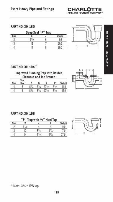
Deep Seal “P” Trap Size X J Weight
2 91⁄2 6 9.8 3 12 7 20.3 4 14 8 29.0
Improved Running Trap with Double Cleanout and Tee Branch
Vent Size Size E G X X’ Weight
4 3 51⁄4 61⁄4 201⁄2 51⁄2 41.8 4 4 53⁄8 61⁄4 201⁄2 51⁄2 42.9
PART NO. XH 180
PART NO. XH 184(T)
“P” Trap with 1⁄2” Heel Tap Size X J A Weight
2 91⁄2 4 4 9.0 3 12 51⁄2 43⁄8 17.0 4 14 61⁄2 45⁄8 27.0
PART NO. XH 198
(T) Note: 31⁄2” IPS tap
EXTRA
HEAVY
120
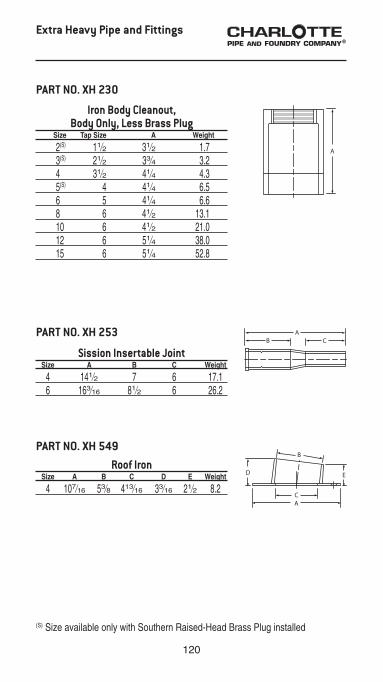
PART NO. XH 549Roof Iron
Size A B C D E Weight
4 107⁄16 53⁄8 413⁄16 33⁄16 21⁄2 8.2
Sission Insertable Joint Size A B C Weight
4 141⁄2 7 6 17.1 6 163⁄16 81⁄2 6 26.2
PART NO. XH 253
Extra Heavy Pipe and Fittings
Iron Body Cleanout,Body Only, Less Brass Plug
Size Tap Size A Weight
2(S) 11⁄2 31⁄2 1.7 3(S) 21⁄2 33⁄4 3.2 4 31⁄2 41⁄4 4.3 5(S) 4 41⁄4 6.5 6 5 41⁄4 6.6 8 6 41⁄2 13.1 10 6 41⁄2 21.0 12 6 51⁄4 38.0 15 6 51⁄4 52.8
PART NO. XH 230
(S) Size available only with Southern Raised-Head Brass Plug installed

121
Plugs
Ohio Code Brass Plug Size D H Weight
10 1023⁄32 21⁄32 10.6
PART NO. PLG 410
Southern Code Brass Plug Size D H Weight
11⁄2 157⁄64 49⁄64 0.2 2 223⁄64 49⁄64 0.3 21⁄2 255⁄64 51⁄64 0.4 3 315⁄32 57⁄64 0.6 31⁄2 363⁄64 57⁄64 0.7 4 431⁄64 61⁄64 1.1 5 535⁄64 61⁄64 1.5 6 619⁄32 17⁄32 2.5 8 839⁄64 19⁄32 4.0
PART NO. PLG 430
Southern Code Countersunk Brass Plug Size D H Weight
11⁄2 157⁄64 13⁄32 0.2 2 223⁄64 7⁄16 0.3 3 315⁄32 33⁄64 0.6 31⁄2 363⁄64 33⁄64 0.8 4 431⁄64 35⁄64 0.9 5 535⁄64 11⁄16 1.7 6 619⁄32 11⁄16 2.3
PART NO. PLG 440
Cast Iron Plug Size D H Weight
6 635⁄64 117⁄64 4.2 10 1039⁄64 131⁄32 9.0
PART NO. PLG 450
PLUGS

122
This is to verify that products manufactured by Charlotte Pipe and Foundry, Cast Iron Division, are manufactured in the United States and conform to the following standards:
SERVICE HUB AND SPIGOT PIPE AND FITTINGSAll cast iron soil pipe and fittings shall be marked with the collective trademark of the Cast Iron Soil Pipe Institute (CISPI).ASTM A 74Listed by NSF® International to the UP CodeISO 9001:2008 Certified
EXTRA HEAVY HUB AND SPIGOT PIPE AND FITTINGSAll cast iron soil pipe and fittings shall be marked with the collective trademark of the Cast Iron Soil Pipe Institute (CISPI).ASTM A 74Listed by NSF® International to the UP CodeISO 9001:2008 Certified
HUBLESS PIPE AND FITTINGSAll cast iron soil pipe and fittings shall be marked with the collective trademark of the Cast Iron Soil Pipe Institute (CISPI).CISPI Standard 301ASTM A 888Listed by NSF® International to the UP CodeISO 9001:2008 Certified
HUBLESS COUPLINGSCISPI Standard 310ASTM C 1277Certified by NSF® International
HUBLESS HEAVY DUTY COUPLINGSMeets ASTM C 1540
COMPRESSION GASKETSASTM C 564CISPI HSN 85

123
LIMITED WARRANTY
Charlotte and Charlotte Pipe are registered trademarks of Charlotte Pipe and Foundry Company.
Charlotte Pipe and Foundry Company® (Charlotte Pipe®) Products are warranted to be free from manufacturing defects and to conform to currently applicable ASTM standards for a period of five (5) years from date of delivery. Buyer’s remedy for breach of this warranty is limited to replacement of, or credit for, the defective product. This warranty excludes any expense for removal or reinstallation of any defective product and any other incidental, consequential, or punitive damages. This limited warranty is the only warranty made by seller and is expressly in lieu of all other warranties, express and implied, including any warranties of merchantability and fitness for a particular purpose. No statement, conduct or description by Charlotte Pipe or its representative, in addition to or beyond this Limited Warranty, shall constitute a warranty. This Limited Warranty may only be modified in writing signed by an officer of Charlotte Pipe.This Limited Warranty will not apply if:1) The Products are used for purposes other than their intended purpose as defined by local
plumbing and building codes, and the applicable ASTM standard.2) The Products are not installed in good and workmanlike manner consistent with normal
industry standards; installed in compliance with the latest instructions published by Charlotte Pipe and good plumbing practices; and installed in conformance with all applicable plumbing, fire and building code requirements.
3) This limited warranty does not apply when the products of Charlotte Pipe are used with the products of other manufacturers that do not meet the applicable ASTM or CISPI standards or that are not marked in a manner to indicate the entity that manufactured them.
4) In hubless cast iron installations, this warranty will not apply if products are joined with unshielded hubless couplings. Charlotte Pipe requires that its hubless cast iron pipe and fittings be joined only with shielded hubless couplings manufactured in accordance with CISPI 310, ASTM C 1277 and certified by NSF® International or with Heavy Duty Couplings meeting ASTM C 1540.
5) The Products fail due to defects or deficiencies in design, engineering, or installation of the piping system of which they are a part.
6) The Products have been the subject of modification; misuse; misapplication; improper maintenance or repair; damage caused by the fault or negligence of anyone other than Charlotte Pipe; or any other act or event beyond the control of Charlotte Pipe.
7) The Products fail due to the freezing of water in the Products.8) The Products fail due to contact with chemical agents, fire stopping materials, thread sealant,
plasticized vinyl products, or other aggressive chemical agents that are not compatible.9) Pipe outlets, sound attenuation systems or other devices are permanently attached to the
surface of Charlotte® PVC, ABS or CPVC products with solvent cement or adhesive glue.Charlotte Pipe products are manufactured to the applicable ASTM or CISPI standard. Charlotte Pipe and Foundry cannot accept responsibility for the performance, dimensional accuracy, or compatibility of pipe, fittings, gaskets, or couplings not manufactured or sold by Charlotte Pipe and Foundry. Any Charlotte Pipe products alleged to be defective must be made available to Charlotte Pipe at the following address for verification, inspection and determination of cause:
Charlotte Pipe and Foundry CompanyAttention: Technical Services
2109 Randolph RoadCharlotte, North Carolina 28207
Purchaser must obtain a return materials authorization and instructions for return shipment to Charlotte Pipe of any product claimed defective or shipped in error.Any Charlotte Pipe product proved to be defective in manufacture will be replaced F.O.B. point of original delivery, or credit will be issued, at the discretion of Charlotte Pipe. 4/24/15
Testing with or use of compressed air or gas in PVC / ABS / CPVC / Cast Iron pipe or fittings can result in explosive failures and cause severe injury or death.
• NEVER test with or transport/store compressed air or gas in PVC / ABS / CPVC / Cast Iron pipe or fittings.
• NEVER test PVC / ABS / CPVC / Cast Iron pipe or fittings with compressed air or gas, or air over water boosters.
• ONLY use PVC / ABS / CPVC / Cast Iron pipe or fittings for water or approved chemicals.
• Refer to warnings on PPFA’s website and ASTM D 1785.
WARRANTY

PO BOX 35430
CHARLOTTE
NORTH CAROLINA 28235
PHONE (704) 348-6450
(800) 438-6091
FAX (800) 553-1605
WWW.CHARLOTTEPIPE.COM