Embed Size (px)
Citation preview
Digital/Analog Audio Controllers Installation Instructions
2001, 2005, 2006, 2011 SimplexGrinnell LP. All rights reserved. Specifications and other information shown were current as of publication and are subject to change without notice. Simplex and the Simplex logo are trademarks of Tyco International Ltd. and its affiliates and are used under license.
579-159 Rev. G
This publication describes the installation procedure for the following: 4100-1210 Analog Audio Controller Board
4100-1211 Digital Audio Controller Board (Order for Field Replacement only)
4100-1311 Digital Audio Controller Board (Constant Supervision)
These products are compatible with 4100U and 4100ES Fire Alarm Control Panels (FACP).
IMPORTANT: Verify FACP System Programmer, Executive, and Slave Software
compatibility when installing, or replacing system components. Refer to the Technical Support Information and Downloads website for compatibility information.
This publication discusses the following topics:
Topic See Page
Cautions, Warnings, and Regulatory Information 2
Introduction to the Audio Controllers 3
Audio Controller Card Specifications 6
Configuring the Audio Controller Card 7
Installing the Audio Controller onto the PDI 9
Audio Controller Field Wiring 10
Installing the Digital Audio PDI Termination Plug 20
Troubleshooting 21
Introduction
In this Publication

2
Cautions and Warnings
READ AND SAVE THESE INSTRUCTIONS- Follow the instructions in this installation manual. These instructions must be followed to avoid damage to this product and associated equipment. Product operation and reliability depend upon proper installation.
DO NOT INSTALL ANY SIMPLEX® PRODUCT THAT APPEARS DAMAGED- Upon unpacking your Simplex product, inspect the contents of the carton for shipping damage. If damage is apparent, immediately file a claim with the carrier and notify an authorized Simplex product supplier.
ELECTRICAL HAZARD - Disconnect electrical field power when making any internal adjust-ments or repairs. All repairs should be performed by a representative or authorized agent of your local Simplex product supplier.
EYE SAFETY HAZARD - Under certain fiber optic application conditions, the optical output of this device may exceed eye safety limits. Do not use magnification (such as a microscope or other focusing equipment) when viewing the output of this device.
STATIC HAZARD - Static electricity can damage components. Handle as follows:
Ground yourself before opening or installing components.
Prior to installation, keep components wrapped in anti-static material at all times.
FCC RULES AND REGULATIONS – PART 15 - This equipment has been tested and found to comply with the limits for a Class A digital device pursuant to Part 15 of the FCC Rules. These limits are designed to provide reasonable protection against harmful interference when the equipment is operated in a commercial environment. This equipment generates, uses, and can radiate radio frequency energy and, if not installed and used in accordance with the instruction manual, may cause harmful interference to radio communications. Operation of this equipment in a residential area is likely to cause harmful interference in which case the user will be required to correct the interference at his own expense. SYSTEM REACCEPTANCE TEST AFTER SOFTWARE CHANGES - To ensure proper system operation, this product must be tested in accordance with NFPA 72® after any programming operation or change in site-specific software. Reacceptance testing is required after any change, addition or deletion of system components, or after any modification, repair or adjustment to system hardware or wiring. All components, circuits, system operations, or software functions, known to be affected by a change, must be 100% tested. In addition, to ensure that other operations are not inadvertently affected, at least 10% of initiating devices that are not directly affected by the change, up to a maximum of 50 devices, must also be tested and proper system operation verified. NFPA 72® is a registered trademark of the National Fire Protection Association.
Cautions, Warnings, and Regulatory Information
3
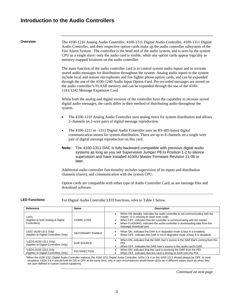
The 4100-1210 Analog Audio Controller, 4100-1211 Digital Audio Controller, 4100-1311 Digital Audio Controller, and their respective option cards make up the audio controller subsystem of the Fire Alarm System. The controller is the head end of the audio system, and is seen by the system CPU as a single slave: only the audio card is visible, while any option cards appear logically as memory-mapped locations on the audio controller. The main function of the audio controller card is to control system audio inputs and to recreate stored audio messages for distribution throughout the system. Analog audio inputs to the system include local and remote microphones and fire fighter phone option cards, and can be expanded through the use of the 4100-1240 Audio Input Option Card. Pre-recorded messages are stored on the audio controller’s FLASH memory and can be expanded through the use of the 4100-1241/1242 Message Expansion Card. While both the analog and digital versions of the controller have the capability to recreate stored digital audio messages, the cards differ in their method of distributing audio throughout the system. The 4100-1210 Analog Audio Controller uses analog risers for system distribution and allows
2 channels on 2-wire pairs of digital message reproduction.
The 4100-1211 or -1311 Digital Audio Controller uses an RS-485-based digital communication means for system distribution. There are up to 8 channels on a single-wire pair of digital message reproduction on this card.
Note: The 4100-1311 DAC is fully backward compatible with previous digital audio
systems as long as you set Supervision Jumper P8 to Position 1-2 to silence supervision and have installed 4100U Master Firmware Revision 11.08 or later.
Additional audio controller functionality includes supervision of its inputs and distribution channels (risers), and communication with the system CPU. Option cards are compatible with either type of Audio Controller Card, as are message files and download software.
For Digital Audio Controller LED functions, refer to Table 1 below.
Reference Name Description
LED1 (Applies to both Analog & Digital Controllers)
COMM_LOSS
When ON steadily, indicates the audio controller is not communicating with the master, or is missing its slave exec code.
When OFF, indicates that the controller is communicating with the master. When FLASHING, indicates the audio controller is downloading data from the
message download port.
LED2 (4100-1311 Only) (Applies to Digital Controllers Only)
SECONDARY ENABLE When ON, indicates the DAR is in degraded mode (Class A is enabled). When OFF, indicates the DAR is not in degraded mode (Class A is disabled).
*LED3 (4100-1311 Only) (Applies to Digital Controllers Only)
DAR SOURCE When ON, indicates that the DAR riser’s source is the DAR that’s coming from the
PDI. When OFF, indicates the DAR riser’s source is this audio card’s DAR.
*LED4 (4100-1311 Only (Applies to Digital Controllers Only)
PDI DIRECTION When ON, indicates that this card is receiving the DAR from the PDI. When OFF, indicates that this card is driving its DAR onto the PDI.
*When the 4100-1311 Digital Audio Controller replaces the 4100-1211 Digital Audio Controller, LEDs 3 & 4 on the 4100-1311 should always be OFF. In most situations, LEDs 3 & 4 should both be ON or OFF at the same time; only in rare circumstances would these LEDs be in different states (such as when they are user-defined in custom control equations).
Continued on next page
Introduction to the Audio Controllers
Overview
LED Functions

4
Figure 1 depicts the analog audio controller.
Figure 1. The 4100-1210 Analog Audio Controller
Continued on next page
Introduction to the Audio Controllers, Continued
Analog Controller Illustration
MESSAGE DOWNLOAD
PORT (P1)
MESSAGE EXPANSION CARD
PORT (P2)
*COMM LOSS LED (LED1)
DOWNLOAD JUMPER (P8)
AUDIO RISER TERMINAL BLOCK (TB1)
INPUT OPTION CARD PORT 1 (P9)
INPUT OPTION CARD PORT 2 (P10)
LOCAL SPEAKER/MIC PORT (P5)
BAUD RATE/ ADDRESS DIP
SWITCH (SW1)
REMOTE MIC TERMINAL BLOCK (TB2)
PDI CONNECTOR (on reverse side)
* LED1 lights when the controller loses communication with the system CPU.
5
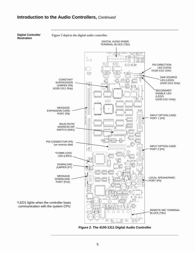
Figure 2 depicts the digital audio controller.
Figure 2. The 4100-1311 Digital Audio Controller
Introduction to the Audio Controllers, Continued
Digital Controller Illustration
MESSAGE DOWNLOAD PORT (P10)
MESSAGE EXPANSION CARD
PORT (P6)
*COMM LOSS LED (LED1)
DOWNLOAD JUMPER (P7)
DIGITAL AUDIO RISER TERMINAL BLOCK (TB2)
INPUT OPTION CARD PORT 1 (P6)
INPUT OPTION CARD PORT 2 (P4)
LOCAL SPEAKER/MIC PORT (P9)
BAUD RATE/ ADDRESS DIP
SWITCH (SW1)
REMOTE MIC TERMINAL BLOCK (TB1)
PDI CONNECTOR (P5) (on reverse side)
* LED1 lights when the controller loses communication with the system CPU.
CONSTANT SUPERVISION JUMPER (P8)
(4100-1311 Only)
PDI DIRECTION LED (LED4)
(4100-1311 Only)
DAR SOURCE LED (LED3) (4100-1311 Only)
SECONDARY ENABLE LED (LED2) (4100-1311 Only)

6
The analog and digital audio controller both use 24 V card power for riser amps and for microphone supervision. All card logic and low-level analog circuitry is powered from the on-board buck regulator (at 5 V). The following specifications apply to analog and digital audio controllers. Minimum input voltage: 19 VDC Maximum input voltage: 33 VDC Maximum ripple: 1 VRMS at 120 Hz Analog current draw:
At 24 VDC
Maximum Over Range
Current Draw (Quiescent of PCA, no conditions below)
225 mA 290 mA
Additional Current draw factors (add to above number for total card current draw)
Local Speaker On - Silence 50 mA 50 mA
Local Speaker On - Min Volume (Horn Tone, 500Hz Square Wave)
75 mA 90 mA
Local Speaker On - Half Volume (Horn Tone, 500Hz Square Wave)
190 mA 190 mA
Local Speaker On - Full Volume (Horn Tone, 500Hz Square Wave)
330 mA 330 mA
Local or Remote Microphone Enabled (Each) 30 mA 40 mA
Digital current draw:
At 24 VDC Maximum Over Range
Current Draw (Quiescent of PCA, no conditions below)
85 mA 100 mA
Additional Current draw factors (add to above number for total card current draw)
Local Speaker On - Silence 50 mA 50 mA
Local Speaker On - Min Volume (Horn Tone, 500Hz Square Wave)
75 mA 90 mA
Local Speaker On - Half Volume (Horn Tone, 500Hz Square Wave)
190 mA 190 mA
Local Speaker On - Full Volume (Horn Tone, 500Hz Square Wave)
330 mA 330 mA
Local or Remote Microphone Enabled (Each) 30 mA 40 mA
The equipment operates normally with ambient temperatures outside the cabinet from 32 to 120 F (0 to 49 C), inclusive. The equipment operates normally under non-condensing humidity conditions up to 93% relative humidity at 90 F (32 C).
Audio Controller Card Specifications
7
1 8 7 6 5 4 3 2
This section describes how to configure the audio controller card. Configuration is the same for analog and digital audio controllers except where indicated.
A jumper is used to select the download speed from the FACP programmer. Use jumper P8 on the analog audio controller. Use jumper P7 on the digital audio controller. Position 1-2: Download speed = 56 K
Position 2-3: Download speed = 115 K (default)
A jumper is used to configure the Digital Audio Controller for backward compatibility. Use jumper P8 to set the compatibility mode. Position 1-2: Silence Supervision (used for backward compatibility when the card is used as a
retrofit or replacement in systems having Digital Audio Riser Interface Cards [566-243] or a Digital Audio Controller [4100-1211]).
Position 2-3: Constant Supervision (default) (used in current systems or systems being retrofitted for constant supervision where all 566-243 Digital Audio Riser Interface Cards [DARICs] and 4100-1211 Digital Audio Controllers [DACs] are being replaced with later versions [566-407 for DARICs & 4100-1311 for DACs])
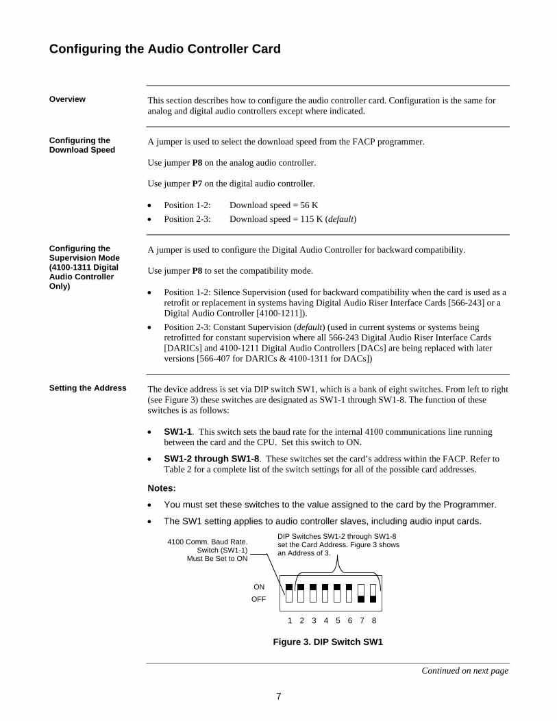
The device address is set via DIP switch SW1, which is a bank of eight switches. From left to right (see Figure 3) these switches are designated as SW1-1 through SW1-8. The function of these switches is as follows: SW1-1. This switch sets the baud rate for the internal 4100 communications line running
between the card and the CPU. Set this switch to ON.
SW1-2 through SW1-8. These switches set the card’s address within the FACP. Refer to Table 2 for a complete list of the switch settings for all of the possible card addresses.
Notes:
You must set these switches to the value assigned to the card by the Programmer.
The SW1 setting applies to audio controller slaves, including audio input cards. FigureTag FD9-159-01
Figure 3. DIP Switch SW1
Continued on next page
Configuring the Audio Controller Card
Overview
Configuring the Download Speed
Configuring the Supervision Mode (4100-1311 Digital Audio Controller Only)
Setting the Address
ON
OFF
DIP Switches SW1-2 through SW1-8 set the Card Address. Figure 3 shows an Address of 3.
4100 Comm. Baud Rate. Switch (SW1-1)
Must Be Set to ON

8
Table 2. Card Addresses
Configuring the Audio Controller Card, Continued
Setting the Address,
Address SW 1-2 SW 1-3 SW 1-4 SW 1-5 SW 1-6 SW 1-7 SW 1-8 Address SW 1-2 SW 1-3 SW 1-4 SW 1-5 SW 1-6 SW 1-7 SW 1-8
1 ON ON ON ON ON ON OFF 61 ON OFF OFF OFF OFF ON OFF
2 ON ON ON ON ON OFF ON 62 ON OFF OFF OFF OFF OFF ON
3 ON ON ON ON ON OFF OFF 63 ON OFF OFF OFF OFF OFF OFF
4 ON ON ON ON OFF ON ON 64 OFF ON ON ON ON ON ON
5 ON ON ON ON OFF ON OFF 65 OFF ON ON ON ON ON OFF
6 ON ON ON ON OFF OFF ON 66 OFF ON ON ON ON OFF ON
7 ON ON ON ON OFF OFF OFF 67 OFF ON ON ON ON OFF OFF
8 ON ON ON OFF ON ON ON 68 OFF ON ON ON OFF ON ON
9 ON ON ON OFF ON ON OFF 69 OFF ON ON ON OFF ON OFF
10 ON ON ON OFF ON OFF ON 70 OFF ON ON ON OFF OFF ON
11 ON ON ON OFF ON OFF OFF 71 OFF ON ON ON OFF OFF OFF
12 ON ON ON OFF OFF ON ON 72 OFF ON ON OFF ON ON ON
13 ON ON ON OFF OFF ON OFF 73 OFF ON ON OFF ON ON OFF
14 ON ON ON OFF OFF OFF ON 74 OFF ON ON OFF ON OFF ON
15 ON ON ON OFF OFF OFF OFF 75 OFF ON ON OFF ON OFF OFF
16 ON ON OFF ON ON ON ON 76 OFF ON ON OFF OFF ON ON
17 ON ON OFF ON ON ON OFF 77 OFF ON ON OFF OFF ON OFF
18 ON ON OFF ON ON OFF ON 78 OFF ON ON OFF OFF OFF ON
19 ON ON OFF ON ON OFF OFF 79 OFF ON ON OFF OFF OFF OFF
20 ON ON OFF ON OFF ON ON 80 OFF ON OFF ON ON ON ON
21 ON ON OFF ON OFF ON OFF 81 OFF ON OFF ON ON ON OFF
22 ON ON OFF ON OFF OFF ON 82 OFF ON OFF ON ON OFF ON
23 ON ON OFF ON OFF OFF OFF 83 OFF ON OFF ON ON OFF OFF
24 ON ON OFF OFF ON ON ON 84 OFF ON OFF ON OFF ON ON
25 ON ON OFF OFF ON ON OFF 85 OFF ON OFF ON OFF ON OFF
26 ON ON OFF OFF ON OFF ON 86 OFF ON OFF ON OFF OFF ON
27 ON ON OFF OFF ON OFF OFF 87 OFF ON OFF ON OFF OFF OFF
28 ON ON OFF OFF OFF ON ON 88 OFF ON OFF OFF ON ON ON
29 ON ON OFF OFF OFF ON OFF 89 OFF ON OFF OFF ON ON OFF
30 ON ON OFF OFF OFF OFF ON 90 OFF ON OFF OFF ON OFF ON
31 ON ON OFF OFF OFF OFF OFF 91 OFF ON OFF OFF ON OFF OFF
32 ON OFF ON ON ON ON ON 92 OFF ON OFF OFF OFF ON ON
33 ON OFF ON ON ON ON OFF 93 OFF ON OFF OFF OFF ON OFF
34 ON OFF ON ON ON OFF ON 94 OFF ON OFF OFF OFF OFF ON
35 ON OFF ON ON ON OFF OFF 95 OFF ON OFF OFF OFF OFF OFF
36 ON OFF ON ON OFF ON ON 96 OFF OFF ON ON ON ON ON
37 ON OFF ON ON OFF ON OFF 97 OFF OFF ON ON ON ON OFF
38 ON OFF ON ON OFF OFF ON 98 OFF OFF ON ON ON OFF ON
39 ON OFF ON ON OFF OFF OFF 99 OFF OFF ON ON ON OFF OFF
40 ON OFF ON OFF ON ON ON 100 OFF OFF ON ON OFF ON ON
41 ON OFF ON OFF ON ON OFF 101 OFF OFF ON ON OFF ON OFF
42 ON OFF ON OFF ON OFF ON 102 OFF OFF ON ON OFF OFF ON
43 ON OFF ON OFF ON OFF OFF 103 OFF OFF ON ON OFF OFF OFF
44 ON OFF ON OFF OFF ON ON 104 OFF OFF ON OFF ON ON ON
45 ON OFF ON OFF OFF ON OFF 105 OFF OFF ON OFF ON ON OFF
46 ON OFF ON OFF OFF OFF ON 106 OFF OFF ON OFF ON OFF ON
47 ON OFF ON OFF OFF OFF OFF 107 OFF OFF ON OFF ON OFF OFF
48 ON OFF OFF ON ON ON ON 108 OFF OFF ON OFF OFF ON ON
49 ON OFF OFF ON ON ON OFF 109 OFF OFF ON OFF OFF ON OFF
50 ON OFF OFF ON ON OFF ON 110 OFF OFF ON OFF OFF OFF ON
51 ON OFF OFF ON ON OFF OFF 111 OFF OFF ON OFF OFF OFF OFF
52 ON OFF OFF ON OFF ON ON 112 OFF OFF OFF ON ON ON ON
53 ON OFF OFF ON OFF ON OFF 113 OFF OFF OFF ON ON ON OFF
54 ON OFF OFF ON OFF OFF ON 114 OFF OFF OFF ON ON OFF ON
55 ON OFF OFF ON OFF OFF OFF 115 OFF OFF OFF ON ON OFF OFF
56 ON OFF OFF OFF ON ON ON 116 OFF OFF OFF ON OFF ON ON
57 ON OFF OFF OFF ON ON OFF 117 OFF OFF OFF ON OFF ON OFF
58 ON OFF OFF OFF ON OFF ON 118 OFF OFF OFF ON OFF OFF ON
59 ON OFF OFF OFF ON OFF OFF 119 OFF OFF OFF ON OFF OFF OFF
60 ON OFF OFF OFF OFF ON ON

9
The audio controller assembly is designed to be mounted on the PDI in an FACP expansion bay. The card should be mounted onto the leftmost side of the PDI. Use the connector on the back side of the audio controller card to connect to the left side of the bay as shown in Figure 4.
Figure 4. Mounting onto the Power Distribution Interface
Installing the Audio Controller onto the PDI
CONTROLLER CARD
STANDOFFS
#6 SCREWS
WASHERS
PDI CONNECTOR (reverse side)
PDI

10
This section contains the field wiring drawings for the analog and digital audio controllers. Input Option Card, Remote Mic, and Line Level wiring diagrams are valid for both the Analog and Digital Controllers. Note: Use supplied ferrite beads with digital audio controllers. Loop wires once
through the supplied ferrite bead(s) as shown in Figure 5.
Figure 5. Loop Wires As Shown.
Figure 6. Audio Input Card Interconnections
Note: Refer to the Fire Alarm System Audio Input Card Installation Instructions
(579-160) for information on the audio input card.
Continued on next page
Audio Controller Field Wiring
Overview
Audio Input Card Interconnections
11
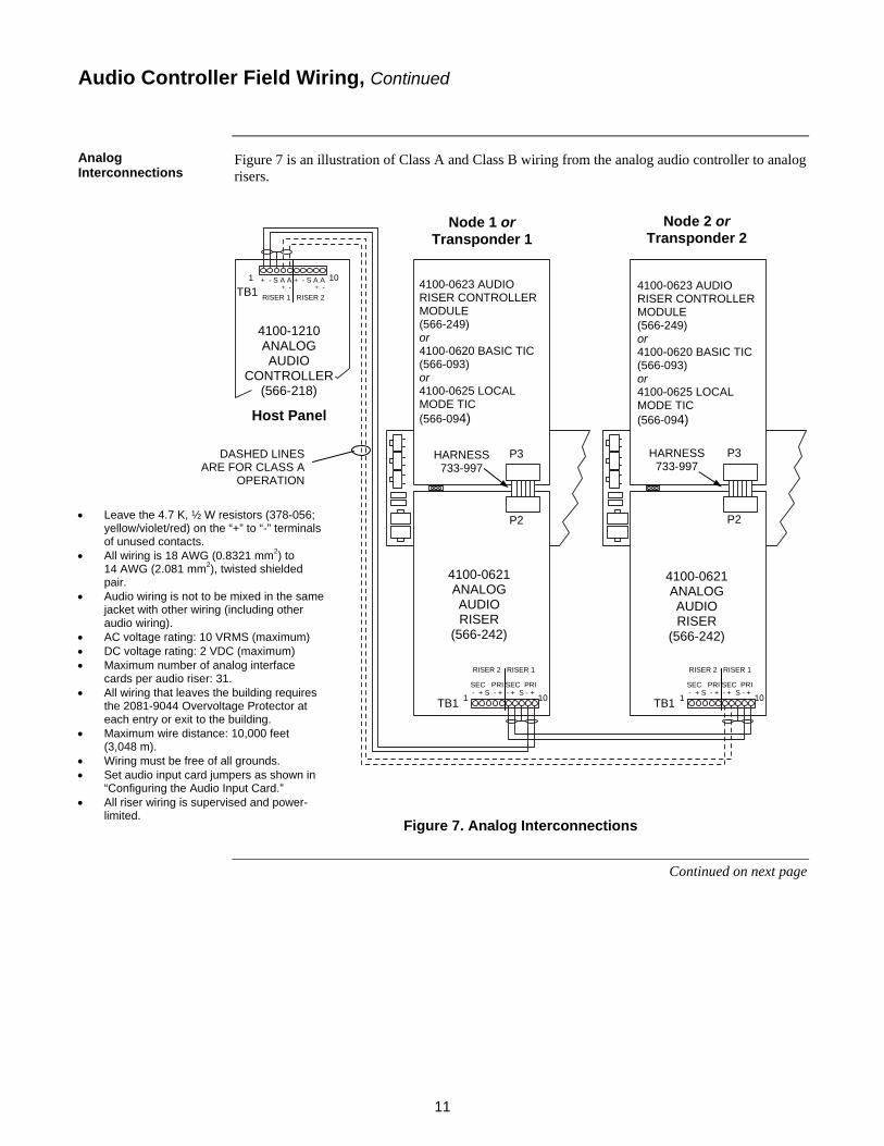
Figure 7 is an illustration of Class A and Class B wiring from the analog audio controller to analog risers.
Figure 7. Analog Interconnections
Continued on next page
Audio Controller Field Wiring, Continued
Analog Interconnections
Leave the 4.7 K, ½ W resistors (378-056; yellow/violet/red) on the “+” to “-” terminals of unused contacts.
All wiring is 18 AWG (0.8321 mm2) to 14 AWG (2.081 mm2), twisted shielded pair.
Audio wiring is not to be mixed in the same jacket with other wiring (including other audio wiring).
AC voltage rating: 10 VRMS (maximum) DC voltage rating: 2 VDC (maximum) Maximum number of analog interface
cards per audio riser: 31. All wiring that leaves the building requires
the 2081-9044 Overvoltage Protector at each entry or exit to the building.
Maximum wire distance: 10,000 feet (3,048 m).
Wiring must be free of all grounds. Set audio input card jumpers as shown in
“Configuring the Audio Input Card.” All riser wiring is supervised and power-
limited.
HARNESS 733-997
HARNESS 733-997
P3 P2
P3 P2
4100-0621 ANALOG AUDIO RISER
(566-242)
4100-0621 ANALOG AUDIO RISER
(566-242)
4100-0623 AUDIO RISER CONTROLLER MODULE (566-249) or 4100-0620 BASIC TIC (566-093) or 4100-0625 LOCAL MODE TIC (566-094)
DASHED LINES ARE FOR CLASS A
OPERATION
Host Panel
Node 1 or Transponder 1
1 10 + - S A A + - S A A
RISER 1 RISER 2
4100-1210 ANALOG AUDIO
CONTROLLER (566-218)
+ - + - TB1
- + S - + - + S - +
RISER 2 RISER 1
TB1 1 10
SEC PRI SEC PRI
RISER 2 RISER 1
TB1 1 10
SEC PRI SEC PRI - + S - + - + S - +
Node 2 or Transponder 2
4100-0623 AUDIO RISER CONTROLLER MODULE (566-249) or 4100-0620 BASIC TIC (566-093) or 4100-0625 LOCAL MODE TIC (566-094)

12
The FACP may be connected to the 4100 Legacy Audio Controller via the FACP Audio Riser and the Network input on the Legacy Controller. The FACP uses a 10VRMS Analog Audio riser. In order to interface to a legacy 4100 Audio Controller Network input, an isolation/step-down transformer must be used. This is an existing product, the Audio Isolator Assembly, PN 742-302. The setup is slightly different from the instructions that are supplied with the module. Following are the modified installation instructions:
1. Connect the incoming nominal 10 VRMS FACP Audio Riser wiring to TB1 on the audio isolator. If the installation requires IN and OUT wiring, two wires may be installed under each screw of TB1.
Note: The in and out wiring must be two separate wires. Do not loop the wire around the TB1 screws.
2. If there is only one audio wire pair coming into the panel, isolate and tape back the shield with high quality electrical tape.
3. If the installation requires IN and OUT wiring, install as indicated in Step 1 above, connect the shields of the incoming and outgoing wires together to maintain continuity of the shield. The preferable method is to twist the shields together, solder and cover with a high quality electrical tape.
Figure 8. Audio Board Controller Configuration
Follow Steps 1 through 5 and Figure 8 to properly align the audio controller board after installing the audio isolator.
1. Ensure the jumper wire on the isolator assembly is connected to Post D. 2. Remove R85, R90, and C118 from the Audio Controller Board (562-894). 3. Verify there is a nominal 10 VRMS riser supervisory signal (1Khz Sine Wave) into the
isolator. 4. Using the AC scale of an appropriate meter (e.g., Fluke 12, Fluke 75) measure the level at
TP6 using TB2-2 of the audio controller as a reference. 5. If needed, adjust R88 on the audio controller for a level of 0.5 VAC.
Audio Controller Field Wiring, Continued
Connecting the Analog Riser to Legacy 4100
Aligning the Audio Controller

13
The low level (1Vp‐p) audio output from the legacy controller to the local amplifiers must be converted from an unbalanced signal to a balanced signal in order to pass the distortion requirements for this configuration. This is accomplished by a new Isolation Transformer harness, PN 0734‐231. If there is more than one amplifier on a channel, additional isolator harnesses must be added between each link in the audio distribution. If the Legacy Controller uses two channel audio, isolation harness’s will be required for the second channel. See Fig. 10:
LEGACYAMPLIFIER
LEGACYAMPLIFIER
MODE 1 MODE 24100U/4100ES MINIPLEXTRANSPONDER
LEGACY MINIPLEXTRANSPONDER
TO ADDITIONNAL AMPLIFIERS(IF REQUIRED)
NEW AUDIOISOLATORHARNESSPN 734-231
NEW AUDIOISOLATORHARNESSPN 734-231
NEW AUDIOISOLATORHARNESSPN 734-231
EXISTING PRODUCT742-302AUDIO ISOLATORASSEMBLY
ADDITIONAL 734-231 HARNESSIF 2 CHANNELS
LEGACYAUDIO CONTROLLER
DASHEDLINES ARE
FOR CLASS AOPERATION
4100-0620BASIC TIC(566-093)
OR 4100-0625LOCAL
MODE TIC(566-094)
4100-0621ANALOGAUDIORISER
(566-242)
4100-1210ANALOGAUDIO
CONTROLLER(566-218)
TB1RISER 1
1 10
RISER 2
S A A S A A
HARNESS733-997
P3
P2
Node 1Miniplex
Transponder
Node 1Host Panel
TB1RISER 1
1 10
RISER 2
SSEC PRI SEC PRI
S
AUDIO BDASSY NO.562-894
IN
TP6
C118
R90
R85
R88
PHONE TOAUDIOAUDIO OUTPUT 3AUDIO OUTPUT 2OUTPUT 1
OUTS S
ISOLATOR
Figure 9. Amplifier and Harness Connections
Audio Controller Field Wiring, Continued
Amplifier and Harness Connections

14
Figure 10. Remote Mic Interconnections
Continued on next page
Audio Controller Field Wiring, Continued
Remote Mic Interconnections
Leave the 10 K, ½ W resistors (378-030; brown/black/orange) on the “+” to “-” terminals of unused contacts.
All wiring is 18 AWG (0.8321 mm2), twisted-shielded pair.
Audio wiring is not to be mixed in the same jacket with other wiring (including other audio wiring).
Supervisory current is 2.4 mA at 24 VDC (nominal).
Maximum wire distance: 4,000 feet (1,219 m).
Wiring must be free of all grounds. Wiring is supervised and power-limited.

15
Figure 11. Audio Input Card/Remote Mic Interconnections
Note: Refer to the Fire Alarm System Audio Input Card Installation Instructions
(579-160) for information on the audio input card.
Continued on next page
Audio Controller Field Wiring, Continued
Audio Input Card/ Remote Mic Interconnections
Leave the 10 K, ½ W resistors (378-030; brown/black/orange) on the “+” to “-” terminals of unused contacts.
All wiring is 18 AWG (0.8321 mm2), twisted-shielded pair. Audio wiring is not to be mixed in the same jacket with other wiring (including
other audio wiring). Supervisory current is 2.4 mA at 24 VDC (nominal). Maximum wire distance: 4,000 feet (1,219 m). Only option card inputs 3 and 4 support remote microphones. Set audio input card jumpers for desired input sources as shown in
“Configuring the Audio Input Card.” Wiring is supervised and power-limited.
16
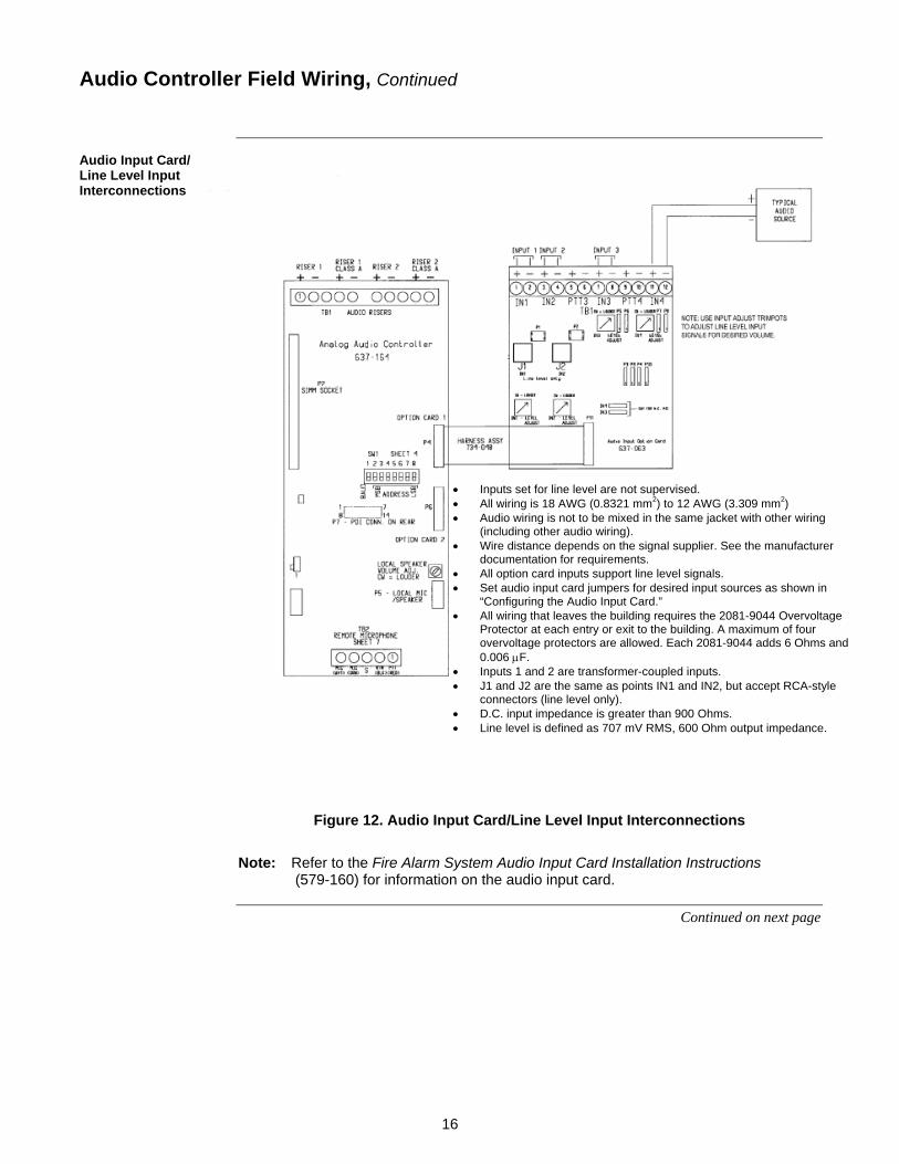
Figure 12. Audio Input Card/Line Level Input Interconnections
Note: Refer to the Fire Alarm System Audio Input Card Installation Instructions
(579-160) for information on the audio input card.
Continued on next page
Audio Controller Field Wiring, Continued
Audio Input Card/ Line Level Input Interconnections
Inputs set for line level are not supervised. All wiring is 18 AWG (0.8321 mm2) to 12 AWG (3.309 mm2) Audio wiring is not to be mixed in the same jacket with other wiring
(including other audio wiring). Wire distance depends on the signal supplier. See the manufacturer
documentation for requirements. All option card inputs support line level signals. Set audio input card jumpers for desired input sources as shown in
“Configuring the Audio Input Card.” All wiring that leaves the building requires the 2081-9044 Overvoltage
Protector at each entry or exit to the building. A maximum of four overvoltage protectors are allowed. Each 2081-9044 adds 6 Ohms and 0.006 F.
Inputs 1 and 2 are transformer-coupled inputs. J1 and J2 are the same as points IN1 and IN2, but accept RCA-style
connectors (line level only). D.C. input impedance is greater than 900 Ohms. Line level is defined as 707 mV RMS, 600 Ohm output impedance.

17
The illustration below shows wiring for a 25 VRMS or 70.7 VRMS input through an audio input option card.
Figure 13. Audio Input Card/Typical Audio Interconnections
Note: Refer to the Fire Alarm System Audio Input Card Installation Instructions
(579-160) for information on the audio input card.
Continued on next page
Audio Controller Field Wiring, Continued
Audio Input Card/ Typical Audio Interconnections
Inputs set for 25 VRMS or 70.7 VRMS audio level are not supervised.
All wiring is 18 AWG (0.8321 mm2) to 12 AWG (3.309 mm2).
Wire distance depends on the signal supplier. See the manufacturer documentation for requirements.
Only inputs 1 and 2 support 25 VRMS/70.7 VRMS audio. Inputs 1 and 2 are transformer-coupled inputs. D.C. input impedance: 60 kiloOhms minimum (25 VRMS
setting). D.C. input impedance: 170 kiloOhms minimum (70.7
VRMS setting). Set audio input card jumpers for desired input sources as
shown in “Configuring the Audio Input Card.”

18
Figure 14 is an illustration of Class A and Class B wiring from the 4100-1211 Digital Audio Controller to the digital audio risers that are in turn connected to TICs for Non-Constant Supervision applications.
Figure 14. Digital Audio Interconnections (4100-1211 Digital Audio Controller)
Continued on next page
Audio Controller Field Wiring, Continued
4100-1211 Digital Audio Controller/ Audio Riser Interconnections (Field Replacement Only [Non-Constant Supervision])
HARNESS 733-997
HARNESS 733-997
P3 P2
P3 P2
Host Panel
Transponder 1 Transponder 2
4100-1211 DIGITAL AUDIO
CONTROLLER (566-033)
4100-0620 BASIC TIC (566-093)
4100-0625 LOCAL
MODE TIC (566-094)
4100-0622 DIGITAL AUDIO RISER
(566-243)
4100-0622 DIGITAL AUDIO RISER
(566-243)
+ - S S + - PRI SEC TB2
6 1
- + S - + SEC PRI TB1
1 6
SEC PRI TB1 1 6
- + S - +
1. All wiring is 24 AWG (0.2047 mm2) to 18 AWG (0.8321 mm2), twisted pair. 2. Maximum wire distance: 2,500 feet (762 meters) from digital audio controller primary to the last
digital audio riser card. 3. Maximum total line distance and capacitance:
18 AWG (0.8321 mm2): 40 Ohms maximum 0.055 F maximum 24 AWG (0.2047 mm2): 135 Ohms maximum 0.055 F maximum
4. All wiring that leaves the building requires the 2081-9044 Overvoltage Protector at each entry or exit to the building. A maximum of four overvoltage protectors are allowed. Each 2081-9044 adds 6 Ohms and 0.006 F.
5. Wiring must be free of all grounds. 6. Maximum number of digital interface cards per digital audio riser: 31. 7. All riser wiring is supervised and power-limited. 8. Audio wiring is not to be mixed in the same jacket with other wiring (including other audio wiring).
PRIMARY DAR
FERRITE BEAD
(required on primary and
secondary DAR)
Loop wires once through the supplied ferrite beads as shown
DASHED LINES ARE FOR CLASS A
OPERATION

19
(For Constant Supervision applications with 4100U Master Firmware Revision 11.08 or later) Figure 15 is an illustration of Class A and Class B digital wiring from the 4100-1311 Digital Audio Controller to the digital audio risers connected to TICs or the Network Audio Riser Controller Module.
NODE N(STYLE 4
ONLY)
NODE P(STYLE 4
ONLY)
DASHEDLINES ARE
FOR CLASS AOPERATION
(required on primaryand secondary DAR)
Loop wires oncethrough the supplied
ferrite beads as shown
DAR TOPRIMARY
INPUT
DAR TOPRIMARY
INPUT
4100-0622DIGITALAUDIORISER
(566-407)
4100-1311DIGITALAUDIORISER
(566-409)
TB3
TB2
TB3 TB3
HARNESS733-997
P3
P2Ferrite Bead
NODE Q(STYLE 4
ONLY)
NODE R(STYLE 4
ONLY)
4100-0622DIGITALAUDIORISER
(566-407)
HARNESS733-997
P3
P2
4100-0622DIGITALAUDIORISER
(566-407)
HARNESS733-997
P3
P2
DAR TOPRIMARY
INPUTNode 1
MiniplexTransponder
Node 1Host Panel
Node 2Control Panel
Node 2Miniplex
Transponder
4100-0620BASIC TIC(566-093)
OR 4100-0625LOCAL
MODE TIC(566-094)
4100-0620BASIC TIC(566-093)
OR 4100-0625LOCAL
MODE TIC(566-094)
4100-0623AUDIO RISERCONTROLLER
MODULE(566-249)
Figure 15. Digital Audio Interconnections (4100-1311 Digital Audio Controller)
Audio Controller Field Wiring, Continued
4100-1311 Digital Audio Controller/ Audio Riser Interconnections (Constant Supervision Applications)
1. All wiring is 24 AWG (0.2047 mm2) to 18 AWG (0.8321 mm2), twisted pair. 2. Maximum wire distance: 2,500 feet (762 meters) from digital audio controller primary to the primary
of the first Digital Audio Riser Interface Card (DARIC). 3. Maximum distance between subsequent nodes: 2,500 feet (762 meters) 4. Maximum line distance and capacitance between nodes:
18 AWG (0.8321 mm2): 40 Ohms maximum, 0.055 F maximum 24 AWG (0.2047 mm2): 135 Ohms maximum, 0.055 F maximum
5. All wiring that leaves the building requires the 2081-9044 Overvoltage Protector at each entry or exit to the building. A maximum of four overvoltage protectors are allowed. Each 2081-9044 adds 6 Ohms and 0.006 F.
6. Wiring must be free of all grounds. 7. Maximum number of digital interface cards per digital audio riser: 31. 8. All riser wiring is supervised and power-limited. 9. Audio wiring is not to be mixed in the same jacket with other wiring (including other audio wiring).

20
A Digital Audio Riser Termination Plug (734-183) is provided with every Digital Audio Controller or Digital Audio Riser Module. You must use this termination plug to properly terminate the Digital Audio Signal on the PDI.
To properly terminate the Digital Audio Signal on the PDI, you must install the termination plug into P7 of the last bay that has Digital Audio. The Digital Audio Controller (or Digital Audio Riser Module) should be the first item and the Digital Audio Termination Plug the last item in the Digital Audio PDI Bay-to-Bay wiring. See Figure 16.
Figure 16. Installing a Digital Audio PDI Termination Plug
Installing the Digital Audio PDI Termination Plug
Overview
Installing the Digital Audio PDI Termination Plug
Place the Digital Audio PDI Termination Plug into P7 of the last bay with Digital Audio.

21
This section describes the messages that may appear on the FACP display when using the audio controller cards and their option cards.
The audio controller card is either not installed or is not at the system address specified by the Programmer.
The wrong card is using the address specified by the Programmer as the audio controller card.
The audio message library in the audio card does not match the version of the audio message library used by the scripts in the FACP master controller. This can happen when changes are made to the messages and only the audio card message library or the FACP configuration was downloaded.
A message memory card is missing from the audio controller, or is present while the controller was configured not to have a message memory card.
Your message memory download was corrupted, your memory expansion card is defective, or your digital audio controller is defective. If you receive this message after a download, try downloading again.
An audio input card is missing from either slot 1 or slot 2 next to the audio controller, or is present while slot 1 or 2 was configured not to have an audio input card.
Additional troubles may be annunciated for shorts or opens on any of the following, each of which is supervised:
Microphone circuit
Analog risers 1 and 2
DAR riser (communication failure)
Troubleshooting
Overview
Card Missing/Failed
Wrong Card
Message Library Mismatch
Message Memory Card Configuration Trouble
Message Memory Checksum Failure
Input Option Card Configuration Trouble
Additional Troubles

579-159 Rev. G