Embed Size (px)
Citation preview

www.aplitop.com
TcpMDT Professional V8 © Aplitop 1
TcpMDT
Digital Terrain Model – V8
Professional
Introduction
The Professional Version is designed to assist the user at all stages of developing a project in the context of Topography and Civil Engineering, including all the functionality of the Standard Version. Its main users are public administrations, construction companies, engineering, architecture and town planning studies and companies involved in earthworks, running quarries, mining, the environment etc. as well as free-lance professionals. MDT is an application that is installed as a plugin on AutoCAD, BricsCAD or ZWCAD. It offers a powerful set of tools for easy learning and has a modular structure. It shows great versatility through the import and export of files in the most common formats, such as LandXML, DWG and many more. In addition, APLITOP is a pioneer in the integration of topographic and road data in OpenBIM workflows, through the IFC format and the extensions IFC Alignment and IFC Road.
Topographic Points
The program starts to run from coordinates obtained by total stations or GNSS receivers, converting files from field applications. If TcpET or TcpGPS has been used, in addition to the coordinates, the raw data of the observations are imported, as well as the linked photographs and voice notes.
It is also possible to create new points from CAD entities drawn by other programs. If codes have been assigned to points in the field, the program will automatically draw the planimetry and blocks defined by the user. In addition, we can run all kinds of editing and filtering operations.

TcpMDT Professional V8 © Aplitop 2
Surfaces
Break lines can be defined graphically, by sequence of points, codes or by importing files. Triangulation can be created from points, with or without break lines and by applying angle or maximum length controls. There are also options for flat triangles minimization and automatic gap repair. Topographic surfaces of natural terrain and geotechnical layers can be created from survey data or seismic profiles.
There are commands for interactive editing of the surface, and it also offers tools to detect and repair errors. The surfaces can have multiple boundaries or islands, and can be drawn as lines, 3D faces or meshes.
Advanced surface operations include tools for creating subgrades with a fixed or variable elevation for implementing earthworks by site or grading elevations, levelled area top, embankment top or bottom, slope between surfaces etc. These commands include options for determining the optimum elevation to balance the cut and fill volumes. The program includes the import and export of the most common formats, including CAD applications, BIM, machine control, 3D modeling and virtual reality.
Contours Lines
MDT can generate contours with an interval or at special elevations and they are updated automatically with each change in triangulation. The contours can be labelled manually or automatically with style, size and layer personalization. Another command allows additional labels to be placed anywhere on the surface.

TcpMDT Professional V8 © Aplitop 3
There are also other commands for interpolating, breaking and joining curves, adding vertices, editing curves, discretizing polylines and splines, detecting elevation errors etc.
Other tools make it possible to import files in shape and formats.
Meshes
Meshes may be created from a surface, contours, 3D entities or mesh files in various known formats (Arc/Info, LAS, GeoTIFF, etc.). It also has commands for mesh processing such as joins, filtering and resampling, conversions etc. They may be represented as 3D faces, polyface mesh or image, all being suitable for export to realism and animation programs.
Horizontal Alignments
The horizontal alignments which will be used on longitudinal and cross sections may be created interactively, drawing on the screen and from polylines, numeric input or importing files in the most usual commercial formats. Other commands also allow alignments to be integrated based on lines, circular arcs and clothoids and which may be fixed, rotating or coupled, greatly making easier the layout drawing. The alignments are automatically dimensioned with customizable styles and their vertices may be edited. It may also be checked whether the radius and setting values comply with the road standards.

TcpMDT Professional V8 © Aplitop 4
MDT includes other tools for labelling curve tables, the generation of reports by intervals, the calculation of distances and intersections between alignments etc. Once the alignment has been generated, superelevations and widenings can be generated, being able to choose the applicable tables according to the country. An MDT road comprises the horizontal and vertical alignment, longitudinal profiles and cross sections, superelevations, widenings and template sections. Then it is possible to draw the project longitudinal profiles and cross sections, represent the modified terrain and obtain all kinds of reports for measurements, settings out etc.
Longitudinal Profiles
The profiles may be calculated based on a surface, 3D cartography or by regression from points near the alignment. The quick profile command allows the user to draw a line on the surface and quickly show the profile.
The profiles may be updated automatically when the original alignment or surface have changed. Furthermore, it has a powerful CAD independent profile editor which allows graphic and numerical editing. The drawing is fully customizable, including the use of paper space or model, sheet templates, style, justification and text sizes. The numerical information to be labelled on the profile can also be chosen from a broad list of elements (distances from origin and partial distances, terrain elevation, gradient elevation, slopes etc.). Blocks defined by the user can also be inserted at the desired locations.
It is possible to represent on one single profile one or several terrains and vertical alignments, including the tables with vertical curve characteristics, curvature diagram and superelevations, intersection with other roads etc. MDT has utilities to draw profiles of power lines including poles, catenaries, etc.

TcpMDT Professional V8 © Aplitop 5
Cross Sections
The terrain cross sections may also be obtained from points, a surface or mesh, 3D cartography or by the conversion of files from the most usual formats. The project profiles are generated, also bearing in mind the standard sections, superelevations and widenings. The drawing is highly customizable in such a way that we can decide on those elements which must be labelled (chainage, terrain elevation, gradient elevation, areas and volumes, superelevation etc.). In addition, we can see them in real time simply by moving the cursor on the drawing on the horizontal alignment or on the longitudinal profile. It is also possible to insert blocks and project 3D polylines on the profiles.
MDT allows users to draw several profiles simultaneously to see different layers or stages of evolution of the project. A powerful editor allows the profiles to be graphically modified by moving the vertices or numerically by modifying distances or elevations. If the original surface or alignment are modified, the profiles may be automatically updated.
MDT also incorporates special commands for drawing piping sections, allowing the definition of their terrain layers, bedding material, pipe diameter etc.
Vertical Alignments
Vertical alignments can be defined from a polyline, parameters (chainage and elevations or distances and slopes) or by importing files. Vertical curves may be circular or parabolic (symmetrical or asymmetrical) and they may be edited by changing their radius or parameter, tangent, maximum ordinate or crossing point, showing all the information about estimated elevations, slopes and volumes in real time. The drawing is updated automatically of the alignment or surface is changed.

TcpMDT Professional V8 © Aplitop 6
MDT includes tools for generating the optimum gradient, applying displacements in chainage or elevation, extracting it from a longitudinal profile, comparing two gradients etc. Compliance with the road standards can also be verified in terms of visibility, slopes and curve characteristics.
Standard Sections
MDT allows the drawing of sections applicable to each segment of an alignment, both on urban and road projects. The platforms are defined from vectors such as lane, median, berm, hard shoulder… The user may create his own vectors library and he may customize the dimensions and behavior of each to decide how to apply superelevations, textures or road surface layers.
The road surface layers may also be defined separately for each platform vector as well as the sub gradient application conditions (constant slope, parallel, depending on the superelevation or variable). We can also apply different inclinations on the left and right of the alignment as well as in the interior or exterior of the median. Finally, different materials can be assigned to each of the road surface layers.
The ditches are defined from vector elements and they may be applied on the left or right and cut or fill. Another option allows the definition of reserve ditches conditioned by the height difference from the natural ground.
There are different options for defining the cut and fill slopes: constant slope, berms or variables. You can also assign conditional slopes for height, layers of geology, slope dimensions, etc. In addition, the standard section may include geology layers, walls and structures, reinforcements and expansions. It also includes tools for the automatic creation of sections from a drawing in top and front views, being able to define geometrically medians, walls, curbs, etc.

TcpMDT Professional V8 © Aplitop 7
Setting out
Setting out bases can be created using various methods and it is possible to set out isolated points, points on an alignment, chainages and displacement, intervals, polyline vertices etc. with their own coordinates or regarding bases.
All set out points are analyzed in line with the alignment, indicating their chainage, displacement and azimuth. It also includes numerous roads setting out tools with the possibility of calculating and analyzing section elements, generating lists of platform vertices, waysides, slopes, vertices, road surface layers, elevations etc.
Other useful commands allow the analysis, control and report on a survey based on a modified terrain digital model and/or on developed design profiles.
Volumes
Cut and fill volumes can be calculated from a comparison between meshes, surfaces or cross sections. The results of meshes and surfaces are represented by areas using color palettes, with a customizable legend and interval.
Calculation by cross sections allows the application of the curvature corrections in line with the geometry of the horizontal alignment and excluding intervals that do not form part of the measurement.
A utility allows you to quickly calculate the volumes of stockpiles of material defined by polylines drawn on a surface.
TcpMDT Professional V8 © Aplitop 8
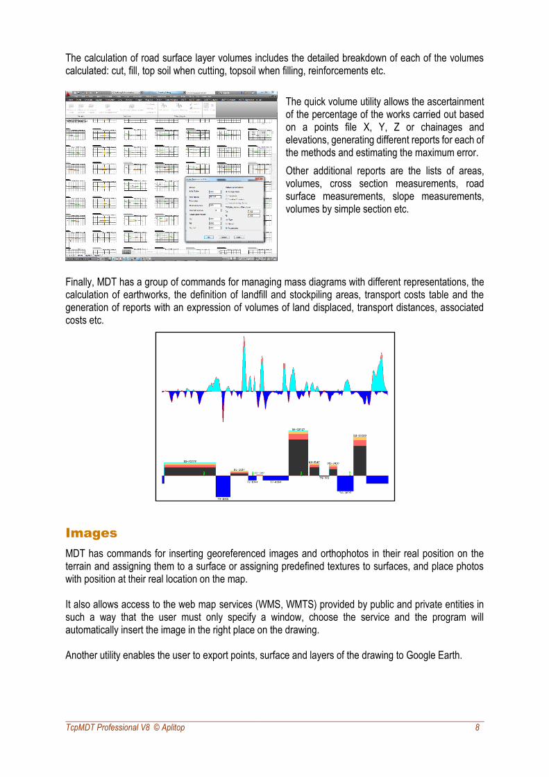
The calculation of road surface layer volumes includes the detailed breakdown of each of the volumes calculated: cut, fill, top soil when cutting, topsoil when filling, reinforcements etc.
The quick volume utility allows the ascertainment of the percentage of the works carried out based on a points file X, Y, Z or chainages and elevations, generating different reports for each of the methods and estimating the maximum error.
Other additional reports are the lists of areas, volumes, cross section measurements, road surface measurements, slope measurements, volumes by simple section etc.
Finally, MDT has a group of commands for managing mass diagrams with different representations, the calculation of earthworks, the definition of landfill and stockpiling areas, transport costs table and the generation of reports with an expression of volumes of land displaced, transport distances, associated costs etc.
Images
MDT has commands for inserting georeferenced images and orthophotos in their real position on the terrain and assigning them to a surface or assigning predefined textures to surfaces, and place photos with position at their real location on the map. It also allows access to the web map services (WMS, WMTS) provided by public and private entities in such a way that the user must only specify a window, choose the service and the program will automatically insert the image in the right place on the drawing. Another utility enables the user to export points, surface and layers of the drawing to Google Earth.
TcpMDT Professional V8 © Aplitop 9
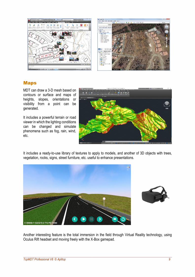
Maps
MDT can draw a 3-D mesh based on contours or surface and maps of heights, slopes, orientations or visibility from a point can be generated. It includes a powerful terrain or road viewer in which the lighting conditions can be changed and simulate phenomena such as fog, rain, wind, etc.
It includes a ready-to-use library of textures to apply to models, and another of 3D objects with trees, vegetation, rocks, signs, street furniture, etc. useful to enhance presentations.
Another interesting feature is the total immersion in the field through Virtual Reality technology, using Oculus Rift headset and moving freely with the X-Box gamepad.
TcpMDT Professional V8 © Aplitop 10
Plots
This menu includes options for creating and editing plots and buildings. It also has tools for plot division by area, parallel and perpendicular to one side, azimuth, length of facade, etc. You can also generate various types of reports, export to GML and shape formats, etc.
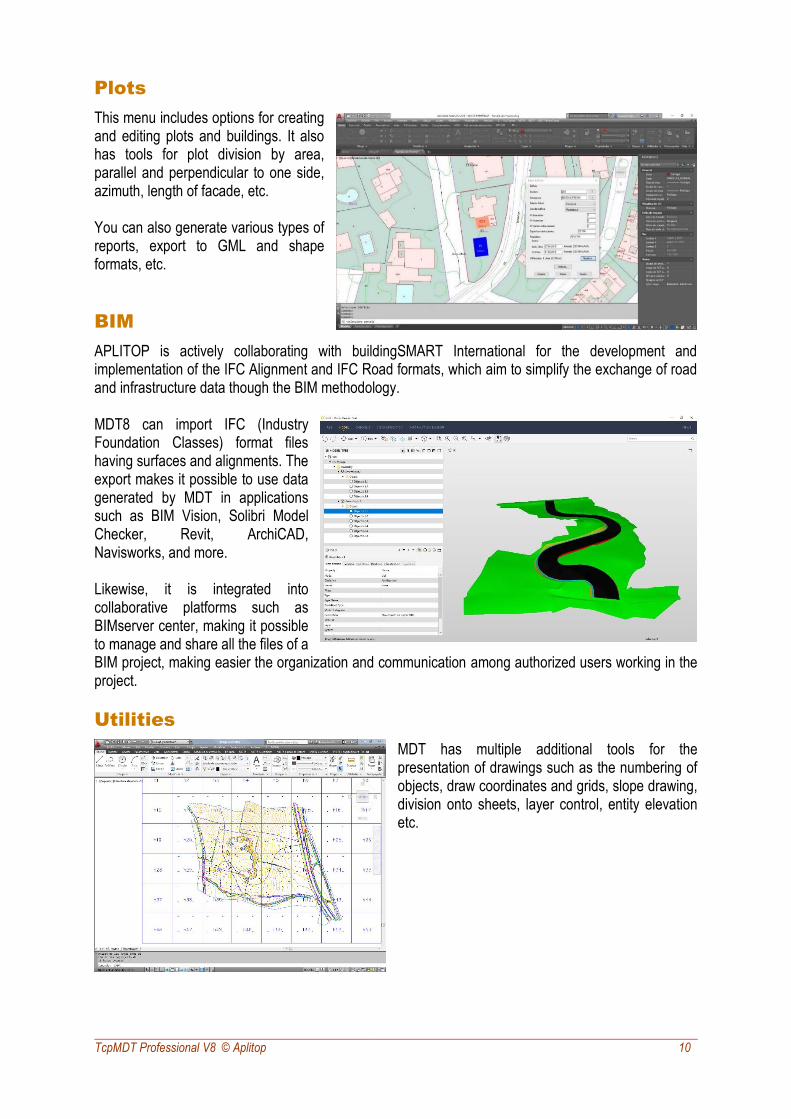
BIM
APLITOP is actively collaborating with buildingSMART International for the development and implementation of the IFC Alignment and IFC Road formats, which aim to simplify the exchange of road and infrastructure data though the BIM methodology. MDT8 can import IFC (Industry Foundation Classes) format files having surfaces and alignments. The export makes it possible to use data generated by MDT in applications such as BIM Vision, Solibri Model Checker, Revit, ArchiCAD, Navisworks, and more. Likewise, it is integrated into collaborative platforms such as BIMserver center, making it possible to manage and share all the files of a BIM project, making easier the organization and communication among authorized users working in the project.
Utilities
MDT has multiple additional tools for the presentation of drawings such as the numbering of objects, draw coordinates and grids, slope drawing, division onto sheets, layer control, entity elevation etc.

TcpMDT Professional V8 © Aplitop 11
Reports
The results offered by MDT can be customized by the user, including its graphic representation and reports. In these you can define the header and footer content, font types, sizes and colors, add company logo, configure margins, line spacing… In addition, the reports can be exported directly to Word, Excel, text, PDF and drawing as a table in the CAD itself.
Requirements (1)
CAD AutoCAD versions 2007 to 2020 and compatible versions
BricsCAD Pro/Platinum versions 12 to 19
ZWCAD Professional/Enterprise versions 2012+ to 2020 and Classic
Operating System Windows 7 / 8 / 8.1 / 10 in 32 and 64 bits (2)
Peripherals Mouse or pointing device
CD-ROM Reader
Graphic Card 1024x768 pixels, compatible with OpenGL
Nvidia or ATI chipset recommended
Drive 5 Gb free space
Memory Minimum 2 Gb
Processor Dual-core 2 Ghz or superior
(1) Consult the website for further details (2) Operation via a remote desktop and similar services are not guaranteed, nor on virtualization platforms. Write to [email protected] to ask about these special cases.
APLITOP S.L. Sumatra,9 – Urb. El Atabal E-29190 Málaga (Spain)
Tel.: +34 95 2439771 e-mail: [email protected] website: www.aplitop.com