Embed Size (px)
Citation preview
DIGITAL MODULATION
Lecture 7
Ir. Muhamad Asvial, MEng., PhDCenter for Information and Communication Engineering Research
Electrical Engineering Department – University of Indonesia Kampus UI Depok, 16424 – Indonesia
[email protected]://www.ee.ui.ac.id
Digital Baseband TransmissionDigital Baseband Transmission• Why to apply digital transmission?• Symbols and bits• Binary PAM Formats• Baseband transmission
– Binary error probabilities in baseband transmission• Pulse shaping
– minimizing ISI and making bandwidth adaptation – maximizing SNR at the instant of sampling - matched filtering– optimal terminal filters
• Determination of transmission bandwidth as a function of pulse shape– Spectral density of Pulse Amplitude Modulation (PAM)
• Equalization - removing residual ISI

Why to Apply Digital Transmission?Why to Apply Digital Transmission?
• Digital communication withstands channel noise, interference and distortionbetter than analog system. For instance in PSTN inter-exchange STP*-links NEXT (Near-End Cross-Talk) produces several interference. For analog systems interference must be below 50 dB whereas in digital system 20 dB is enough. With this respect digital systems can utilize lower quality cabling than analog systems
• Regenerative repeaters are efficient. Note that cleaning of analog-signals by repeaters does not work as well
• Digital HW/SW implementation is straightforward• Circuits can be easily reconfigured and preprogrammed by DSP techniques
(an application: software radio)• Digital signals can be coded to yield very low error rates• Digital communication enables efficient exchanging of SNR to BW-> easy
adaptation into different channels• The cost of digital HW continues to halve every two or three years
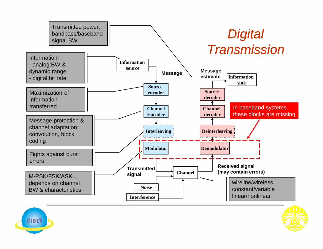
DigitalDigitalTransmissionTransmission
Information:- analog:BW & dynamic range- digital:bit rate
Maximization of information transferred
Transmitted power;bandpass/baseband signal BW
Message protection & channel adaptation;convolution, block coding
M-PSK/FSK/ASK..., depends on channel BW & characteristics
wireline/wirelessconstant/variablelinear/nonlinear
Noise
Interference
Channel
Modulator
ChannelEncoder
Source encoder
Channel decoder
Source decoder
Demodulator
Information sink
Information source
Message Message estimate
Received signal(may contain errors)Transmitted
signal
Interleaving
Fights against burst errors
Deinterleaving
In baseband systemsthese blocks are missing

Formatting and transmission of baseband Formatting and transmission of baseband signalsignal
ec][symbols/s /1 TR [bits/sec] /1 bb TR
Sampling at rate
(sampling time=Ts)
Quantizing each sampledvalue to one of the
L levels in quantizer.
Encoding each q. value to bits
(Data bit duration Tb=Ts/l)
EncodePulse
modulateSample Quantize
Pulse waveforms(baseband signals)
Bit stream(Data bits)Format
Digital info.
Textual info.
Analog info.
source
Mapping every data bits to a symbol out of M symbols and transmitting
a baseband waveform with duration T
ss Tf /1 Ll 2log
Mm 2log

Channel ModelChannel Model
Discrete
Source
Series to
ParallelMapper Waveform
Selector
WaveformDetectorDemapperParallel to
Series
Discrete
sink
+
channels
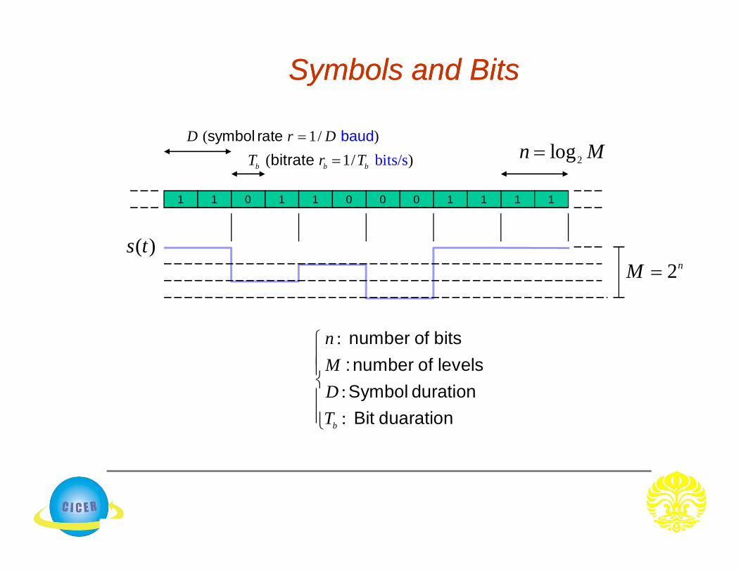
Symbols and BitsSymbols and Bits
:
::
number of bits: number of levels Symbol durationBit duaration
b
nMDT
1 1 00 1 11 110 1 0
bi ( 1/ ) ts/sb b bT r Tbitrate ( 1/ )D r Dsymbol rate baud
2nM
2logn M
( )s t

1 1 0 1 0 0 0 1 0 1 1 0
1
0
10110100
10110100
111101100110
010011001000
Binary Modulation
Quaternary Modulation
Octonary Modulation
)(8 tx ASK
)()(2 txtx BPSKASK
)(4 tx ASK
)(8 tx ASK

Pulse Shaping and BandPulse Shaping and Band--limited Transmission limited Transmission
• In digital transmission signaling pulse shape is chosen to satisfy the following requirements:– yields maximum SNR at the time instance of decision (matched
filtering)– accommodates signal to channel bandwidth:
• rapid decrease of pulse energy outside the main lobe in frequency domain alleviates filter design
• lowers cross-talk in multiplexed systems

Demodulation and detectionDemodulation and detection
• Major sources of errors:– Thermal noise (AWGN)
• disturbs the signal in an additive fashion (Additive)• has flat spectral density for all frequencies of interest (White)• is modeled by Gaussian random process (Gaussian Noise)
– Inter-Symbol Interference (ISI)• Due to the filtering effect of transmitter, channel and receiver, symbols are
“smeared”.
Format Pulse modulate
Bandpassmodulate
Format Detect Demod.& sample
)(tsi)(tgiim
im̂ )(tr)(Tz
channel)(thc
)(tn
transmitted symbol
estimated symbol
Mi ,,1M-ary modulation
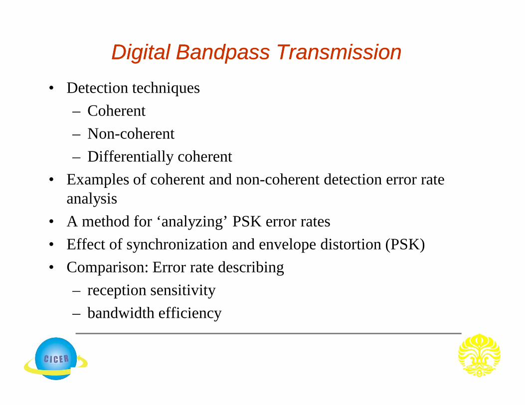
Digital Bandpass TransmissionDigital Bandpass Transmission• Detection techniques
– Coherent– Non-coherent– Differentially coherent
• Examples of coherent and non-coherent detection error rate analysis
• A method for ‘analyzing’ PSK error rates• Effect of synchronization and envelope distortion (PSK)• Comparison: Error rate describing
– reception sensitivity– bandwidth efficiency
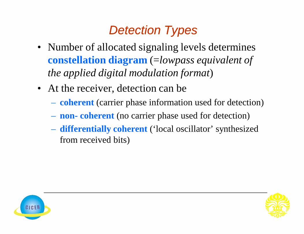
Detection TypesDetection Types• Number of allocated signaling levels determines
constellation diagram (=lowpass equivalent of the applied digital modulation format)
• At the receiver, detection can be– coherent (carrier phase information used for detection)– non- coherent (no carrier phase used for detection)– differentially coherent (‘local oscillator’ synthesized
from received bits)

( ) ( )h t s t
0( ) ( ) ( )v t s t y d
( )v T
( )v T
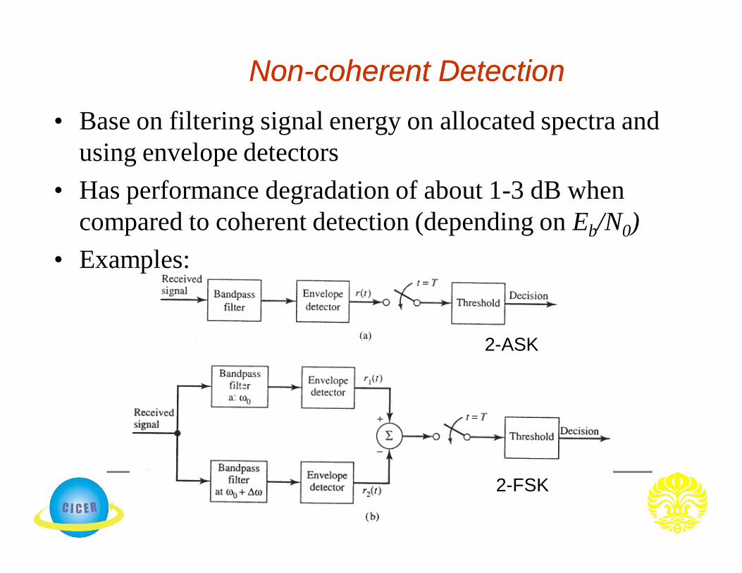
NonNon--coherent Detectioncoherent Detection
2-ASK
2-FSK
• Base on filtering signal energy on allocated spectra and using envelope detectors
• Has performance degradation of about 1-3 dB when compared to coherent detection (depending on Eb/N0)
• Examples:

Error Rate ComparisonError Rate Comparison
a: Coherent BPSKb: DPSKc:Coherent OOKd: Noncoherent FSKe: noncoherent OOK

Comparison of Quadrature Modulation Comparison of Quadrature Modulation MethodsMethods
APK=MQASK