Embed Size (px)
Citation preview

Slide 1
ANALOG MODULATIONIr. Muhamad Asvial, MSc., PhD
Center for Information and Communication Engineering Research (CICER)Electrical Engineering Department - University of Indonesia
E-mail: [email protected]://www.ee.ui.ac.id/~cicer

Slide 2Model of a
communication system
Transmitter
Receiver
Discrete
Source
Source
encoder
Channel
encoderModulator
Channel
DemodulatorChannel
decoder
Source
decoder
Discrete
sink

Slide 3
What is Modulation ?
Modulation is a process to adapt a given signal to a given channel. Most often it means „shifting in frequency“.
Why it is used?
• Besides, transmission of signals at lower frequencies is in general more difficult.
• No waste of available bandwidth (e.g. in wireless comm.)
• For many baseband signals, the wavelengths are too large for reasonable antenna dimension. (e.g. speech signals).
Definition of Modulation

Slide 4 Ideal modulator
The carrier signal might be:
• The information is hidden in the carrier amplitude AM (Linear Modulation).
• The information is hidden in the carrier phase PM (Non-linear Modulation).
• The information is hidden in the carrier frequency FM (Non-linear Modulation).

Slide 5 Amplitude Modulation (AM)
• Test signal
• AM signal
• Amplitude modulated sinusoidal signal with
oscillation with oscillation with

Slide 6 Amplitude Modulation (AM)
• Test signal:
• AM signal:• Amplitude modulated sinusoidal signal with
Phase reversalenvelope
envelope

Slide 7 Fourier Transform of AM

Slide 8 Power of AM with sinusoidal input
Power of an AM modulated sinusoidal signal

Slide 9
The general transmitted AM-signal is given by
Bandlimited Signal
For envelope demodulation we require
it follows
which reminds to
Hence, the degree of modulation is defined as

Slide 10 Double-Side-Band AMwC
The Fourier-transform of is obtained as

Slide 11
envelopes
Representative spectrum

Slide 12
Power of AM is given by
Power of AM signal
with a carrier power of
and a „mean“ power of
and a power needed for transmission of

Slide 13
A practical example (MW, 110 channels)
Band spreading factor
Band spreading factor
bandwidth of the modulated signalsum of bandwidth of all source signals
30Hz 4.5kHz 510kHz 520kHz 1600kHz

Slide 14
Demodulation can be achieved in two principal different ways:
1- Using a time-variant system
An example is the multiplication of with a sinusoidal function .
2- Using a non-linear system
An example for a non-linear system is given by or
.
Demodulation of DSBAMwC

Slide 15
where the index DAM indicates the Demodulation of AM-signals,
with FOURIER-transform
Demodulation with time-variant system

Slide 16
The next figure shows with
Demodulation-Figure

Slide 17
Demodulated output signal:
• Why is the division of by two?
• cannot be suppressed by an additional highpass filter as long as has non-zero mean, why?
• Synchronous demodulation and arbitrary degree of modulation
• A channel with a possible delay and/or a scale factor , so
• For DAM the receiver needs to know . Is it possible,why?
Conclusions

Slide 18
We consider an ideal modulator with modulating function
Unknown Phase
where instead of so that
FOURIER-transforming of leads to

Slide 19
Is it possible to exactly reconstruct without knowing the carrier phase? Yes, by tricky applying .
Unknown Phase

Slide 20 QADM

Slide 21QAM

Slide 22
• Cross talk phenomenon
• QAM for data transmisiion than speech transmission
If the receiver exhibits a frequency shift of , i.e.
has to fullfill
Frequency Shift
it follows

Slide 23
DRC-demodulator in case of rectangular excitation
DRC-demodulator

Slide 24
The choice of is essential for the performance.
The DRC-demodulator in case of
DRC-demodulation

Slide 25 DRC-enhancement „AVD“

Slide 26 DRC-enhancement AVD
Hence

Slide 27DRC-enhancement AVD

Slide 28 DRC-enhancement SLD
We will assume that this equals to
Hence,

Slide 29DRC-enhancement SLD
It follows

Slide 30
By use of it follows
where
Alternative generation of SSBAM

Slide 31
Alternative circuit for generating an SSBAM-signal
Generation of SSBAM

Slide 32 Analytic signal
The analytic signal is also given by , hence
Analytic signal and equivalent
low pass signal are related by:
where is an arbitrary phase.

Slide 33
We will try to figure out in case of SSBAM.
We obtain the equivalent lowpass spectrum:
Hence,
Analytic signal for SSB
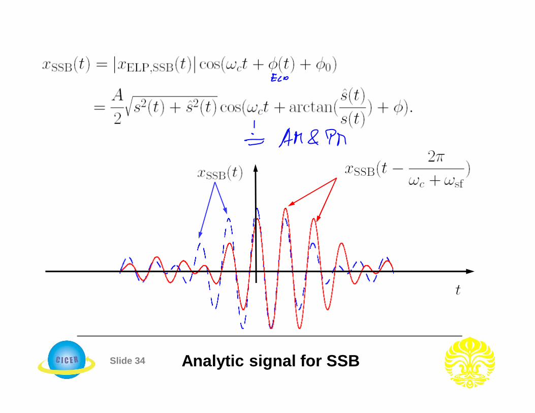
Slide 34 Analytic signal for SSB

Slide 35
In case of a sinusoidal carrier we obtain
Power of SSB

Slide 36
Can be synchronously demodulated ?
Hence, if then
It follows for the envelope
Demodulation of SSBAM

Slide 37
In addition, by use of
we finally obtain
Synchronous demod. (unknown carrier frequency and phase):
Demodulation of SSBAM

Slide 38
The lowpass cut-off frequency has to fulfill
With it follows (see next slide):
Fourier transform yields
Unknown phase & carrier

Slide 39 Unknown phase & carrier
We define and as the lower and the upper edge frequencies of respectively. Let us sketch .

Slide 40
Let us assume that the frequency error can be neglected
Unknown phase
• The human ear can be modelled as a bank of filters, which are insensitive to phase pertubations
• SSBAM receives much attention for transmission ofspeech, but QAM for transmission of data.

Slide 41 VSBAM modem
Consider the DSBAMsC-signal
The transmitted VSB-signal yields
Again we will consider an error in the carrier frequency and unknown phase ; it follows
and the transmit filter response
with Fourier transform

Slide 42 VSBAM demodulation

Slide 43 VSBAM demodulation
Band spreading factor of VSBAM:
It follows
which simplifies for known carrier phase to

Slide 44 An overview of AM
Method TX Power TX costs RX costs
Purpose
DSBAMwCenv.dem.DSBAMwCsync.dem.
QAM
DSBAMsCSSBAMsCSSBAMwCVSBAMsCVSBAMwC
2 high low low2 high low low
2 low moderate high2 low moderate high1 very low moderate/high high1 very low moderate/high high
>1 very low moderate/high high>1 very low moderate/high high1 high moderate low1 high moderate low
2 moderate low high Data-, stereo-sig.
2 moderate low high Data-, stereo-sig.
1 Low/moderate high high speech, audio-sig.
1 Low/moderate high high speech, audio-sig.
>1 high moderate low TV-signals>1 high moderate low TV-signals