Embed Size (px)
Citation preview
EO
CR
CA
T_E
N
2008
Sam
wha
EO
CR
Ltd
.-A
ll rig
hts
rese
rved
.
Digital Electronic O
ver Current R
elays
Head Office6th floor, Jeil Bldg., 94-46, Youngdeungpo-Dong 7Ka, Youngdeungpo-Ku, Seoul, KoreaTel. 82 2 3473 2340 / Fax 82 2 3473 1159Iksan Plant574, Yongie-dong, Iksan-shi, Junbuk, KoreaTel. 82 63 835 5033 / Fax 82 63 835 4175www.eocr.com 10/2008

Application typePMR, SDDR, EVR-FD, EGRVoltage protection managementDC motor protection managementShut Down Delay FunctionLoad Limiter function
Application products except ACovercurrent protection.
Digital type3DM, FDMThe first multi function digital relay.Display trip causes and load factor.Ground fault protection
(Earth leakage current display) Registered as a new power technology No.5.
(Ministry of commerce, Industry and energy)Integrated components
(Ammeter, Transducer, A/S switch, Timer etc.)
Analog typeSS, SP, DS3, DZThe first electronic motor protection relayNew technology against thermal
overload realysEasy to use10 Million pieces have been sold

New Digitali-Series (i3DM, iFDM)Integrated model, Improved functionsModbus RS-485 CommunicationRoHS CompliantSupport thermal inverse protection
DM-Series (3DM2, FDM2)Integrated model, Improved functions RoHS Compliant
Contents
1. Selection guide 4
2. i Series (with Communication) 9Specifications 11Front face 12Setting menu 14Trip indication 17TCC curve 18Typical wiring 19Dimension 22Ordering 24
3. DM2 series 27Specifications 29Front face 30Setting menu 32Trip indication 34TCC curve 35Typical wiring 36Dimension 39Ordering 40
4. Technical guide 44General information 44Technical infotmation 45Setting guide 47Troubleshooting guide 49Communication guide 50

New digital
New Digitali-Series (i3DM, iFDN)Integrated model, Improved functionsModbus RS-485 CommunicationConformed to RoHSSupport thermal inverse protection
DM-Series (3DM2, FDM2)Integrated model, Improved functions Modbus RS-485 CommunicationSupport thermal inverse protection
Old model Measurement Operation Reset Mounting Protections function Additional function New modelmethod TCC
3DD
3DE
3DM
FD
FDE
FDM
3DZ
3EZ
3MZ
FDZ
FEZ
FMZ
3D420
3E420
3M420
FD420
FE420
FM420
3DS
3MS
FDS
FMS
3CT
3CT
3CT
3CT
Definite
TCC
Inverse
TCC
Definite
TCC
Inverse
TCC
Definite
TCC
Inverse
TCC
Definite
TCC
Inverse
TCC
Manual
Manual
Manual
auto
Manual
Manual
Manual
auto
Manual
Manual
Manual
auto
Manual
Manual
Manual
auto
Manual
Manual
Manual
auto
Manual
Manual
Manual
auto
Manual
Manual
auto
Manual
Manual
auto
Panel
Din-Rail
Panel
Din-Rail
Flush mount
Panel
Din-Rail
Panel
Din-Rail
Flush mount
Panel
Din-Rail
Panel
Din-Rail
Flush mount
Panel
Din-Rail
Panel
Din-Rail
Flush mount
Overcurrent,
Phase loss,
Phase reversal,
Lock rotor,
Imbalance
Overcurrent,
Phase loss,
Phase reversal,
Lock rotor,
Imbalance
Overcurrent,
Phase loss,
Phase reversal,
Lock rotor,
Imbalance
Overcurrent,
Phase loss,
Phase reversal,
Lock rotor,
Imbalance
-
Under
current
-
Under
current
-
Under
current
-
Under
current
-
Under
current
-
Under
current
-
Under
current
-
Under
current
-
Ground
Fault
-
Short
circuit
Alert
-
-
-
-
-
-
-
-
-
-
-
-
-
Trip cause display
Trip cause display-store thelatest three histories.
Bar graph, Running hour timer, Trip cause display-store thelatest three histories.
Bar graph, Trip cause display
Bar graph, Trip cause display-store the latest three histories.
Bar graph, Running hour timer, Trip cause display-store thelatest three histories.
Bar graph, Trip cause display
Bar graph, Running hour timer, Trip cause display-store thelatest three histories.
Bar graph, Trip cause display
Bar graph, Running hour timer, Trip cause display-store thelatest three histories.
3DM2
or
i3DM
FDM2
or
iFDM
3MZ2
or
i3MZ
FMZ2
or
iFMZ
i3M420
iFM420
i3MS
iFMS
Selection guide
4
Contents
1. Selection guide 4
2. i Series (with Communication) 9Specifications 11Front face 12Setting menu 14Trip indication 17TCC curve 18Typical wiring 19Dimension 22Ordering 24
3. DM2 series 27Specifications 29Front face 30Setting menu 32Trip indication 34TCC curve 35Typical wiring 36Dimension 39Ordering 40
4. Technical guide 44General information 44Technical infotmation 45Setting guide 47Troubleshooting guide 49Communication guide 50

New digital
Model
Control voltage
Frequency
Single phase
Three phase
Window hole
CT type Bottom hole
Terminal
Overcurrent
Undercurrent
Stall
Jam
Protection Phase loss
function Phase reversal
Imbalance
Ground fault
Short circuit
Thermal inverse
4-20mA output
Alert output
Bar graph
Display
Password functionAdditional
Fail safe ON/OFFfunctionTrip cause display and Store
Total running hour
Running hour timer
Reset
Comm. protocol
Existing model
New digital New digital with Communication
3DM2/ FDM2
AC/DC 100 ~ 240V
DC/AC 24V
50/60 Hz
-
-
-
-
A, F, H
5 Digit 7 Segment
-
Manual/Auto/Electric
-
3DD, 3DE, 3DM
FD, FDE, FDM
3MZ2/ FMZ2
AC/DC 100~240V
DC/AC 24V
50/60 Hz
-
-
-
-
5 Digit 7 Segment
-
-
Manual/Auto/Electric
-
3DZ, 3EZ, 3MZ
FDZ, FEZ, FMZ
i3DM / iFDM
AC/DC 100~240V
DC/AC 24V
50/60 Hz
-
-
-
A, F, H
5 Digit 7 Segment
Manual/Auto/Electric
MODBUS RS-485
3DD, 3DE, 3DM
FD, FDE, FDM
i3MZ / iFMZ
AC/DC 100~240V
DC/AC 24V
50/60 Hz
-
-
-
5 Digit 7 Segment
-
Manual/Auto/Electric
MODBUS RS-485
3DZ, 3EZ, 3MZ
FDZ, FEZ, FMZ
i3M420 / iFM420
AC/DC 100~240V
DC/AC 24V
50/60 Hz
-
-
-
5 Digit 7 Segment
-
Manual/Auto/Electric
MODBUS RS-485
3D420, 3E420, 3M420
FD420, FE420, FM420
i3MS / iFMS
AC/DC 100~240V
DC/AC 24V
50/60 Hz
-
-
-
5 Digit 7 Segment
-
Manual/Auto/Electric
MODBUS RS-485
3DS, FDS, 3MS, FMS
Old reference New reference Display CableOption
ZCT
3DD-05DB, 3DD-60DB, 3DE-WRDB, 3DM-WRDB
3DD-05DZ7, 3DD-60DZ7, 3DE-WRZF7, 3DE-WRDZ7,
3DMWRDZ7
FD-05DBW(T), FD-60DBW(T), FDE-WRDBW(T),
FDMWRDBW(T)
FD-05DZ7W(T), FD-60DZ7W(T), FDE-WRDF7W(T),
FDMWDZ7W(T), 3DM-WDZ7W(T)
3DZ-05ABA(B), 3DZ-60ABA(B), 3EZ-WRABA, 3MZWRABA(B)
3DZ-05CBA(B), 3DZ-60CBA(B), 3MZ-WRCBA(B)
3DZ-05AZ7A(B), 3DZ-60AZ7A(B), 3EZ-WRAF7A, 3EZ-WRAM7A,
3MZ-WRAZ7W(T)A(B)
3DZ-05CZ7A(B), 3DZ-60CZ7A(B), 3MZ-WRCZ7W(T)A(B)
3DZ-05DBA(B), 3DZ-60DBA(B), 3MZ-WRDBA(B)
3DZ-05DZ7A(B), 3DZ-60DZ7A(B), 3MZ-WRDZ7W(T)A(B)
FDZ-05ABW(T)A(B), FDZ-60ABW(T)A(B), FEZ-WRABW(T)A,
FMZ-WRABW(T)A(B)
FDZ-05CBW(T)A(B), FDZ-60CBW(T)A(B), FMZWRCBW(T)A(B)
FDZ-05DBW(T)A(B), FDZ-60DBW(T)A(B), FMZWRDBW(T)A(B)
FDZ-05AZ7W(T)A(B), 3DZ-60AZ7W(T)A(B), FEZWRAF7W(T)A,
3EZ-WRAM7W(T)A, 3MZ-WRABW(T)A(B)
FDZ-05CZ7W(T)A(B), 3DZ-60CZ7W(T)A(B), FMZWRCZ7W(T)A(B)
FDZ-05DZ7W(T)A(B), 3DZ-60DZ7W(T)A(B), FMZWRDZ7W(T)A(B)
3D420-059, 3D420-609, 3E420-WR9, 3M420-WR9
3D420-053, 3D420-603, 3D420-056, 3D420-606, 3E420-WR91,
3M320-WR3, 3M420-WR6
FD420-0539, FD420-6039, FD420-0569, FD420-6069,
FE420-WR91(3), FM420-WR91(3)
FD420-0531(3), FD420-6031(3), FD420-0561(3), FD420-6061(3),
FE420-WR3(1), FE420-WR6(1), FM420-WR31(3), FM420-WR61(3)
3DS-05DB, 3DS-20DB, 3MS-05DB, 3MS-20DB
3DS-05DZ7, 3DS-20DZ7, 3MS-05DZ7, 3MS-20DZ7
FDS-05DBW(T), FDS-20DBW(T), FMS-05DBW(T),
FMS-20DBW(T)
FDS-05DZ7W(T), FDS-20DZ7W(T), FMS-05DZ7W(T),
FMS-20DZ7W(T)
3DM2-WRDBW(T)
3DM2-WRDBH(T)
3DM2-WRDUW
3DM2-WRDUH
FDM2-WRDBW
FDM2-WRDBH
FDM2-WRDUW
FDM2-WRDUH
3MZ2-WRABW
3MZ2-WRABH
3MZ2-WRCBW
3MZ2-WRCBH
3MZ2-WRDBW
3MZ2-WRDBH
3MZ2-WRAUW
3MZ2-WRAUH
3MZ2-WRCUW
3MZ2-WRCUH
3MZ2-WRDUW
3MZ2-WRDUH
FMZ2-WRABW
FMZ2-WRABH
FMZ2-WRCBW
FMZ2-WRCBH
FMZ2-WRDBW
FMZ2-WRDBH
FMZ2-WRAUW
FMZ2-WRAUH
FMZ2-WRCUW
FMZ2-WRCUH
FMZ2-WRDUW
FMZ2-WRDUH
i3M420-WRDBW
i3M420-WRDBH
i3M420-WRDUW
i3M420-WRDUH
iFM420-WRDBW
iFM420-WRDBH
iFM420-WRDUW
iFM420-WRDUH
i3MS-WRDBW
i3MS-WRDBH
i3MS-WRDUW
i3MS-WRDUH
iFMS-WRDBW
iFMS-WRDUH
iFMS-WRDBW
iFMS-WRDUH
-
-
-
-
EOCR-PDM
EOCR-PDM
EOCR-PDM
EOCR-PDM
-
-
-
-
-
-
-
-
-
-
-
-
EOCR-PDM
EOCR-PDM
EOCR-PDM
EOCR-PDM
EOCR-PDM
EOCR-PDM
EOCR-PDM
EOCR-PDM
EOCR-PDM
EOCR-PDM
EOCR-PDM
EOCR-PDM
-
-
-
-
EOCR-PDM
EOCR-PDM
EOCR-PDM
EOCR-PDM
-
-
-
-
EOCR-PDM
EOCR-PDM
EOCR-PDM
EOCR-PDM
-
-
-
-
CABLE-RJ45-xxx
CABLE-RJ45-xxx
CABLE-RJ45-xxx
CABLE-RJ45-xxx
-
-
-
-
-
-
-
-
-
-
-
-
CABLE-RJ45-xxx
CABLE-RJ45-xxx
CABLE-RJ45-xxx
CABLE-RJ45-xxx
CABLE-RJ45-xxx
CABLE-RJ45-xxx
CABLE-RJ45-xxx
CABLE-RJ45-xxx
CABLE-RJ45-xxx
CABLE-RJ45-xxx
CABLE-RJ45-xxx
CABLE-RJ45-xxx
-
-
-
-
CABLE-RJ45-xxx
CABLE-RJ45-xxx
CABLE-RJ45-xxx
CABLE-RJ45-xxx
-
-
-
-
CABLE-RJ45-xxx
CABLE-RJ45-xxx
CABLE-RJ45-xxx
CABLE-RJ45-xxx
-
-
-
-
-
-
-
-
ZCT-xxx
ZCT-xxx
ZCT-xxx
ZCT-xxx
ZCT-xxx
ZCT-xxx
ZCT-xxx
ZCT-xxx
ZCT-xxx
ZCT-xxx
ZCT-xxx
ZCT-xxx
ZCT-xxx
ZCT-xxx
ZCT-xxx
ZCT-xxx
ZCT-xxx
ZCT-xxx
ZCT-xxx
ZCT-xxx
ZCT-xxx
ZCT-xxx
ZCT-xxx
ZCT-xxx
-
-
-
-
-
-
-
-
-
-
-
-
-
-
-
-
Selection guide
65 7


9
EOCR-i Series (with communication)Basic model : EOCR-i3DM (Z, S, 420) / iFDM (Z, S, 420)
Micro-Controller Unit based Real time processing / High precisionProtections : Over current, Under current, Phase loss, Phase reversal, Stall, Jam, Current imbalance,
Earth fault (i3MZ/iFMZ), Short circuit (i3MS/iFMS)Thermal protection / Inverse available up to 32Amps without external CTs.Auxiliary functions : Fail safe, Pre-alarm (i3DM/iFDM), Accumulated running hour, 3 fault records &
limitation of auto-restart. Analog output (i3M420/iFM420). Communication : Modbus / RS-485Reinforced monitoring function : Monitoring distance up to 400M, 3 phase current display, Pre-alarm
(i3DM/iFDM) & Trip cause indication Bar graph indication of a load current to the current setting.Available application on single and 3 phase motor RoHS ComplianceFor iFDM/iFMZ/iFMS/iFM420, normal protections are guaranteed even if PDM is disconnected.
General features
EOCR-i3DM Window type
EOCR-iFDM Bottom hole type EOCR-iFDM Window type
EOCR-i3DM Terminal type EOCR-iFDM Terminal type
EOCR-i3DM Bottom hole type

10
EOCR-i Series (with communication)Basic model : EOCR-i3DM (Z, S, 420) / iFDM (Z, S, 420)
Protection item Condition & Setting range Operation time
Over current (oc)Condition : Load current (In) exceeds setting current (Is) Definite (Def) : 0.2~30s Adjust.
Setting range : 0.5~60A (Def), 0.5~32A (Inv & th) Inverse (Inv) & Thermal (th) : 1~30 class
Under current (uc)Condition : Load current (In) less than setting currentIn ≤ uc
oFF, 1~10s Adjustableuc should be less than oc setting
Phase loss (PL)Condition : max imbalance is more than 85% among 3 phase current,
oFF, 0.5~5s AdjustableEnable or disable : Selectable
Reverse phase (RP)Condition : Reversed phase sequence input on EOCR.
Within 0.15sEnable or disable : Selectable
Condition : In ≥ Stall current setting (Sc). Active only in motor starting
Stall (Sc)0.5~30A : 2~8 times of oc setting
Right after D-time elapsed~40A : 2~6 times,
~60A : 2~4 times.
Condition : In ≥ Jam current setting (JA). Active only in motor running
Jam (JA) 0.5~50A : 1.5~5 times of oc setting 0.2~5s Adjustable
~60A : 1.5~4 times of oc setting
Imbalance (IM) Condition : Current imbalance ≥ Setting imbalance %
1~10s AdjustableSetting range : 10~50% of imbalance
Earth fault (EF)Condition : EF current (Ie) exceeds setting current (Ies) 0.05~5s Adjustable
OFF, 0.03~10A -- i3MZ/iFMZ only --
Condition : SC current (Is) exceeds setting current (Iss)0.05sec
Short circuit (SH) 0.5~10A : 2~22 times of oc setting,-- i3MS/iFMS only --
~20A : 2~11 times of oc setting
Protection functions
Password For secured setting parameters
Communication Monitoring currents and trip status by network
Phase selection For single phase / three phase motor selection
TCC selection Available three time-current-characteristics (Definite, Inverse, Thermal inverse)
CT ratio For the current setting more than 60A (20A : i3MS/iFMS) and less than 0.5A
Fail safe selection Fail safe operation for OL trip output
Pre alarm selection Pre alarm signaling by the 07-08 output contact -- i3MS/iFDM only --
Total running hour Total accumulated running hour from the installation which cannot be modified and reset .
Running hour Display or provied a time-out signal to the 07-08 output contact. -- i3MS/iFDM only --
Reset mode Manual / Auto / Electrical ; selectable
Trip cause memory Store the latest 3 trip causes
Restart limitation The maximum auto-restart number within 30 minutes in auto-reset mode.
Auxiliary functions

11
EOCR-i Series (with communication)Basic model : EOCR-i3DM (Z, S, 420) / iFDM (Z, S, 420)
Model i3DM / iFDM, i3MZ/iFMZ, i3MS/iFMS, i3M420/iFM420
Over current Rated setting range (A) Definite TCC : 0.5~60A. : use external CT higher than 60A
i3MS/iFMS : 0.5~20A : use external CT higher than 20A
Inverse & th TCC : 0.5~32A. use external CT higher than32A
Under current Rated setting range (A) 0.5A ~ less than oc setting
Operating time characteristics Definite(Def) / Inverse(Inv) / Thermal(th)
Time setting Def D-time 0~200s
O-time 0.2~30s
Inv & th (cLS) 1~30 classes
GF delay time (Edt) 0~30s (i3MZ/iFMZ)
GF O-time (Et) 0.05~10s (i3MZ/iFMZ)
SH delay time (SHd) 0~30s (i3MS/iFMS)
SH O-time Within 0.05s fixed (i3MS/iFMS)
Auto-reset 0.5s~20min.
Reset mode Manual reset (H-r) / Electric reset (E-r) / Auto-reset (A-r)
Control power Voltage 100~240VAC/DC(85% ~110%, Free voltage), 24VAC/DC(±5%)
Frequency 50/60Hz
Power consumption Lower than 7VA
Output Capacity 3A/250VAC resistive.
Composition 1a1b : OC (i3DM/iFDM, i3MS/iFMS, i3M420/iFM420)
1a : GR (i3MZ/iFMZ), or AL (i3DM/iFDM), or SH (i3MS/iFMS)
Display 7 segment LED 3 phase amps, Cause of trip, Setting parameters indication.
Bar-graph Load factor.
Communication Modbus/ RS-485
Mounting Panel mounting (i3DM/i3MZ/i3MS/i3M420)
Flush mounting (iFDM/iFMZ/iFMS/iFM420)
Insulation Between case & Circuit Over DC500V 10MΩ
Dielectric strength Between case & Circuit 2kV, 50/60Hz, I Min.
Between contacts 1kV, 50/60Hz, I Min.
Between circuit 2kV, 50/60Hz, 1 Min
Electrostatic discharge (ESD) IEC61000-4-2 Level 3 : Air discharge : ±8KV, Contact discharge : ±6KV
Radiated disturbance IEC61000-4-3 Level 3 : 10V/m, 80 ~ 1000MHz
Conducted disturbance IEC61000-4-6 Level 3 : 10V,0.15~80MHz
EFT/Burst IEC61000-4-4 Level 3 : ±2KV, 1 Min
Surge IEC61000-4-5 Level 3 : 1.2 x 50µs, ±4KV (0˚, 90˚, 180˚, 270˚)
Emission CISPR11 Class A ( Conducted and radiated)
Environment Temperature Store -40˚C ~ +85˚C
Operation 20˚C ~ +60˚C
Humidity 30~85% RH ( Non-condensate)
Dimension Window type 70W × 74.5H × 83.8D
Bottom hole type 70W × 56.3H × 108.1D
Weight i3DM / i3MZ / i3MS / i3M420 iFDM / iFMZ / iFMS / iFM420
Window type 330g 420g
Bottom hole type 370g 460g
Terminal type 370 + 120(PDM) = 490g 460 + 120(PDM) = 580g
Display (W/3M cable) - 125g
Power consumption Less than 7VA.
Specifications
65 70 75 80 85 90 95 100%
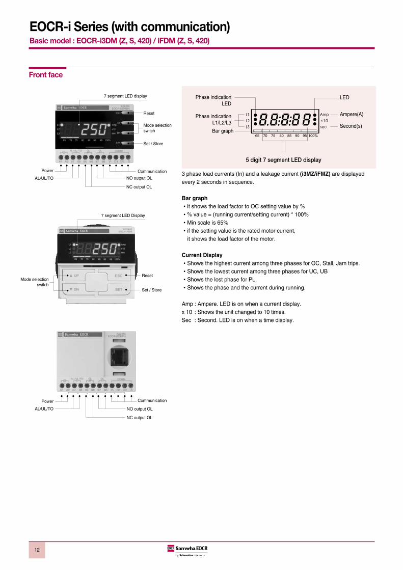
5 digit 7 segment LED display
Phase indicationLED
Phase indicationL1/L2/L3
Bar graph
LED
Ampere(A)
Second(s)
12
EOCR-i Series (with communication)Basic model : EOCR-i3DM (Z, S, 420) / iFDM (Z, S, 420)
Front face
3 phase load currents (In) and a leakage current (i3MZ/iFMZ) are displayedevery 2 seconds in sequence.
Bar graphit shows the load factor to OC setting value by % % value = (running current/setting current) * 100%Min scale is 65%if the setting value is the rated motor current,
it shows the load factor of the motor.
Current DisplayShows the highest current among three phases for OC, Stall, Jam trips. Shows the lowest current among three phases for UC, UBShows the lost phase for PL.Shows the phase and the current during running.
Amp : Ampere. LED is on when a current display. x 10 : Shows the unit changed to 10 times.Sec : Second. LED is on when a time display.
7 segment LED display
Reset
Set / Store
Mode selectionswitch
NO output OL
NC output OL
CommunicationPower
AL/UL/TO
NO output OL
NC output OL
CommunicationPower
AL/UL/TO
7 segment LED Display
Mode selectionswitch
Reset
Set / Store

13
EOCR-i Series (with communication)Basic model : EOCR-i3DM (Z, S, 420) / iFDM (Z, S, 420)
L1 current display
2sec
2sec
2sec 2sec
L2 current display
Rotate
L3 current displayEarth leakage current
3 phase digital ammeter function
※ Blocking display rotation can be done by pressing the SET button once during running. whenever press the SETbutton, the each phase current displays by turns. A fixed phase current display can be done by this.
※ Pressing the ESC button, it returns to the Auto current display rotation mode.
※ Fault history check : Pressing the ESC button more than 5sec, it displays the latest fault cause and the fault current orfault phase. Continuing to press DN button, you can see the current of L1(R), L2(S), L3(T), (GR) in turn. press the DNbutton again to check the previous fault continually. In the latest fault display, the 100% LED of bar graph lights on andtwo LEDs of 95%, 100% lights on for the second fault display, three LEDs of 90%, 95%, 100% lights on for the oldestfault display. When you press the ECS button in this mode, it returns to the normal current display mode. The oldestfault record is over written when the number of fault to record exceeds three.
Button Description
Navigate menus by pressing UP/DN button.
Select a parameter to change, then the parameter starts blinking.
Modify a parameter value by pressing UP/DN button.
Memorize the values in the relay by pressing SET button. blinking stops toshow it’s stored.
Pressing ESC button, it returns to the current display. Without pressing ESC button, it returns to the load current display in 50sec automatically.
Buttons and setting sequence
i3MZ(S) / iFMZ(S)only
i3MZ / iFMZonly
i3MS / iFMSonly
i3M420 / iFM420 only
i3DM / iFDM only
i3DM / iFDM only
Setting sequence
(iXXZ Type only)

14
EOCR-i Series (with communication)Basic model : EOCR-i3DM (Z, S, 420) / iFDM (Z, S, 420)
No. Menu Parameter Description Default
Setting sequence and menu
Use password other than zero for secured settings. This feature enables
limitation of setting modification by unauthorized person. Zero value is used
for disabling password checking.
“Ph:3Ph” mode for a 3 phase load, “Ph:1Ph” mode for a 1 phase load should
be selected. If you select the “Ph:1Ph”, RP, PL and Ub functions will be
disabled and not displayed in the menu mode
Time-current characteristic(TCC) setting. “dE” is for definite TCC, “In” is for
inverse TCC, “th” is for thermal Inverse TCC. Refer to the time-current
characteristic curve. If tcc=no, only overcurrent protection is disabled
External CT ratio setting mode. This is applied to definite TCC; higher than 60A
and inverse TCC; higher than 32A. Set the primary value of the external CT.
For example, 200:5 CT, setting is “ct:200”. For the low-range current “ct: 2t”
is for 2 pass through, “ct: 5t” is for 5 pass through.
Select “ct:non” in case of no externel CT and no loop.
Frequency setting mode. Select 50 or 60 based on the system fundamental
frequency.
Selection of fail safe(No volt release) mode for overload trip output, OL.
Refer to fail-safe operation
Enable or disable reverse phase detection
Threshold for over current protection . this value cannot be set below the
under current threshold (uc).
Motor starting delay, OC, UC, Stall, Jam, Ub are blocked during starting but
PL, RP are not blocked. For “In” TCC mode, ,the cold curve is appled before
dt expires and, the hot curve is applied after dt expires.
(tcc:dE) ; the fault(over current) duration of definite overcurrent protection.
(tcc:In) ; the trip class for inverse overcurrent protection(refer to TCC curve)
(tcc:th) ; the thermal overload protection based on the thermal image by
load current (refer to TCC curve).
Threshold for under current protection. The setting should be higher than
no-load current of a motor. The current value cannot be set higher than OC.
Fault (under current) duration for the under current Operation. If the setting
of “oFF” in the “uc” mode is selected, this menu is not displayed
Threshold for earth fault protection. The capacitance leakage current of the
motor and cable should be taken into account for the setting. The threshold
value corresponds to the primary current of ZCT
Earth fault duration (Trip delay time)
TCC is definite characteristic
Blocking time of Earth Fault detection during motor starting.
OFF, 1~30s adjustable This timer is only active during motor starting.
Threshold for short circuit detection.
This value is the multiples of the over current threshold (oc).
The SC fault duration is fixed to 0.05 second.
1 Pass word
2Selection of Phase No.
3 Operation curve
4 CT ratio
5Frequency
#1, #2
6 Fail safe
7Reversed phase
detection
8Over current
threshold
9 Start delay time
Over current
10duration
(Trip delay time / Trip class )
11Under current
threshold
12Under current duration
(Trip delay time)
13Earth fault
#1(Ground fault)
threshold
14 Earth fault#1 trip delay time
15 EF starting#1 delay
16 Short circuit#2 current threshold

15
EOCR-i Series (with communication)Basic model : EOCR-i3DM (Z, S, 420) / iFDM (Z, S, 420)
Blocking time of short circuit detection during motor starting.
This timer is only active during motor starting.
Enable or disable phase loss(Single phasing) detection. If the “Ph:1Ph” is
selected, this menu is not displayed.
Fault duration for phase loss operation. The setting range is 0.5~5 sec. if
“PL:oFF” is selected, this menu is not displayed
Threshold for current imbalance operation. To disable the function, set to
“oFF”, the setting range is 10~50%.
Imbalance factor (%) = (Imax phase - Imin_phase) / Imax_phase x 100%
Imbalance fault duration (trip delay time) for current imbalance operation.
The setting range is 1~10 seconds.
Threshold for locked rotor detection during motor starting. The value is the
multiples of the over current threshold(oc). If the locked rotor condition is
detected, the trip relay operates in 0.5s after the “dt” expires.
If dt=0, this function is disabled and not displayed in the menu.
Setting range : oc=0.4~30A:2~8times, oc < 40A:2~6times, otherwise
(oc<60A) : 2~4times, (with Ext. CT : 2~8times)
Threshold for locked rotor detection during motor running. The value is the
multiples of the over current threshold (oc).
Setting : oc=0.4~50A : 1.5~5times, otherwise (oc<60A) : 4times, (with Ext. CT : 15~5times)
Jam fault duration (trip delay time)
Setting : 0.2~10 sec
Reference value for max analog output (20mA)
If the load current is equal or greater than this value, analog output is
fixed to 20mA
Threshold of Alert output, set by % of the over current threshold (oc). If the
load current is higher than this value, alert output(07-08 contact) is energized
according to the setting of “ALo : XX”.
If the load current is detected, alert output(07-08 contact) is energized. The
alert threshold is no meaning for this operation.
Refer to the alert operation pattern.
If the load current is higher than the alert threshold, alert output(07-08
contact) repeats open for 1s and close for 1s (flickering), The flickering starts
from the motor starting.
Refer to the alert operation pattern.
If the load current is higher than the alert threshold, alert output(07-08 contact)
is closed (holding) and remains closed until the load current decrease under
the alert threshold. The alert output is blocked during motor starting.
Refer to the alert operation pattern.
If the accumulated running hour is more than the running hour threshold,
the alert output repeats close for 1s and open for 1s.
The alert output is used only for under current protection. If this mode is
selected, a trip by an under current fault is signaled through alert output
(07-08), instead of overload trip output(95-96 or 97-98).
17 SC starting #2 delay
18 Phase loss
19Phase loss
time
20Imbalance threshold
21Imbalance fault
duration
22Stall
threshold
23 Jam threshold
24 Jam fault duration
25 420 Output#3 range
26 Alert#4
No. Menu Parameter Description Default
Setting sequence and menu
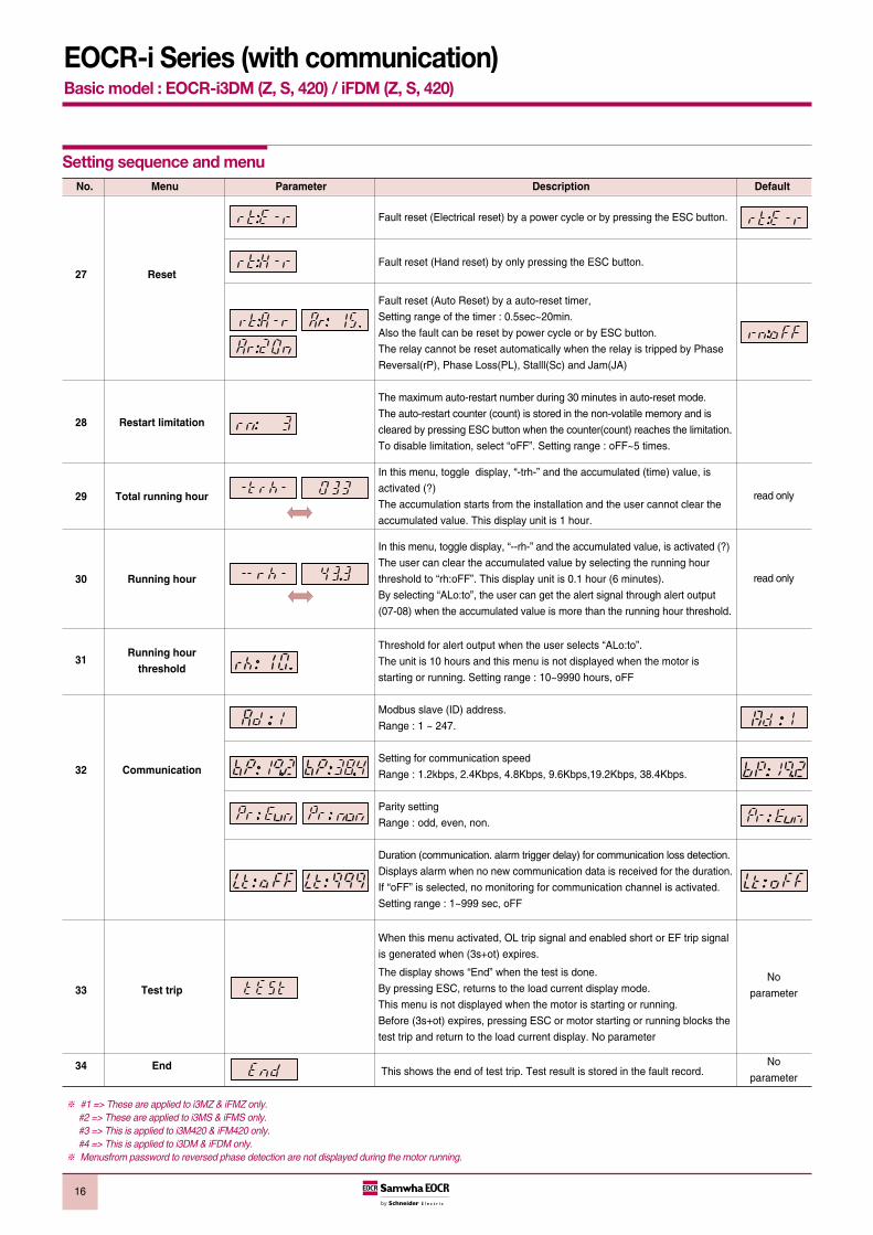
※ #1 => These are applied to i3MZ & iFMZ only.#2 => These are applied to i3MS & iFMS only.#3 => This is applied to i3M420 & iFM420 only.#4 => This is applied to i3DM & iFDM only.
※ Menusfrom password to reversed phase detection are not displayed during the motor running.
16
EOCR-i Series (with communication)Basic model : EOCR-i3DM (Z, S, 420) / iFDM (Z, S, 420)
Fault reset (Electrical reset) by a power cycle or by pressing the ESC button.
Fault reset (Hand reset) by only pressing the ESC button.
Fault reset (Auto Reset) by a auto-reset timer,
Setting range of the timer : 0.5sec~20min.
Also the fault can be reset by power cycle or by ESC button.
The relay cannot be reset automatically when the relay is tripped by Phase
Reversal(rP), Phase Loss(PL), Stalll(Sc) and Jam(JA)
The maximum auto-restart number during 30 minutes in auto-reset mode.
The auto-restart counter (count) is stored in the non-volatile memory and is
cleared by pressing ESC button when the counter(count) reaches the limitation.
To disable limitation, select “oFF”. Setting range : oFF~5 times.
In this menu, toggle display, “-trh-” and the accumulated (time) value, is
activated (?)
The accumulation starts from the installation and the user cannot clear the
accumulated value. This display unit is 1 hour.
In this menu, toggle display, “--rh-” and the accumulated value, is activated (?)
The user can clear the accumulated value by selecting the running hour
threshold to “rh:oFF”. This display unit is 0.1 hour (6 minutes).
By selecting “ALo:to”, the user can get the alert signal through alert output
(07-08) when the accumulated value is more than the running hour threshold.
Threshold for alert output when the user selects “ALo:to”.
The unit is 10 hours and this menu is not displayed when the motor is
starting or running. Setting range : 10~9990 hours, oFF
Modbus slave (ID) address.
Range : 1 ~ 247.
Setting for communication speed
Range : 1.2kbps, 2.4Kbps, 4.8Kbps, 9.6Kbps,19.2Kbps, 38.4Kbps.
Parity setting
Range : odd, even, non.
Duration (communication. alarm trigger delay) for communication loss detection.
Displays alarm when no new communication data is received for the duration.
If “oFF” is selected, no monitoring for communication channel is activated.
Setting range : 1~999 sec, oFF
When this menu activated, OL trip signal and enabled short or EF trip signal
is generated when (3s+ot) expires.
The display shows “End” when the test is done.
By pressing ESC, returns to the load current display mode.
This menu is not displayed when the motor is starting or running.
Before (3s+ot) expires, pressing ESC or motor starting or running blocks the
test trip and return to the load current display. No parameter
This shows the end of test trip. Test result is stored in the fault record.
27 Reset
28 Restart limitation
29 Total running hour
30 Running hour
31Running hour
threshold
32 Communication
33 Test trip
34 End
No. Menu Parameter Description Default
Setting sequence and menu
read only
read only
No
parameter
No
parameter

17
EOCR-i Series (with communication)Basic model : EOCR-i3DM (Z, S, 420) / iFDM (Z, S, 420)
Trip indication
Trip Indication after trip with UP/ DN button pressing
Trip cause Indication Contents of indication L1 LED on L2 LED on L3 LED on
Over currentOC Trip caused by r(L1)-
phase current
Phase lossPhase Loss caused by r(L1)-
phase lost
Reversed phase Phase reversal trip
StallStall trip during motor starting
caused by s(L2)-phase curren
JamJam trip during motor running
caused by t(L3)-phase current
ImbalanceImbalance trip caused by t(L3)-
phase current
Under currentUnder current trip caused by
s(L2)-phase current
Earth fault Earth fault(Earth leakage) trip with
(i3MZ/iFMZ) Earth fault current indication
Short circuit Short Circuit trip caused by
(i3MS/iFMS) s(L2)-phase current
Limitation of In 30minutes, the number of auto-restar For emergency restart, manual reset by pressing ESC clears the restart
auto-restart by auto-reset exceeds the setting counter to zero.
3 fault records including the trip cause and 3phase currents are stored in a non-volatile memory.When the motor is running or stopped, trip cause can be navigated by pressing ESC button over 5seconds
Trip cause indication and fault records
ALo “A” : Ampere relay function (The 07-08 output contact isclosed when a current is detected)
ALo “F” : Flickering ( When a current flows, the output contact isclosed and repeating the close and open on it in a highercurrent than the AL setting.)
ALo “H” : Holding (The output contact is closed in a higher currentthan the AL setting).
ALo “uc” : Applied to “uc” (under current protection) output contact.ALo “to” : When a running hour time is elapsed over the “rh” set
value, the output contact repeats the close - open.
ON
OFF
Alert operation pattern (i3DM & iFDM only)
Fail-safe operation
Aux ( )
Flicker ( )
Hold ( )
Fail-Safe A1-A2 not poweredA1-A2 powered and A1-A2 powered
under normal operation and Tripped
Starting Norma TripOperation
RunningStage
Higher than the presetAlert value
ALo Selection

18
EOCR-i Series (with communication)Basic model : EOCR-i3DM (Z, S, 420) / iFDM (Z, S, 420)
Time-current characteristic curve
Current[Multiples of current setting]
Current[Multiples of current setting]
Definite characteristic
Current[Multiples of current setting]
Thermal inverse characteristic
Inverse characteristic

19
EOCR-i Series (with communication)Basic model : EOCR-i3DM (Z, S, 420) / iFDM (Z, S, 420)
Setting range Number of pass through the CT hole External CT ratio CT Setting Remark
0.5 ~ 60A 1 No CT combination
0.25 ~ 3A 2 No CT combination
0.1 ~ 1.2A 5 No CT combination
0.5 ~ 32A 1 No CT combination Inverse TCC orthermal Inverse TCC
0.5 ~ 60A 1 No CT combination Definite TCC
10 ~100A 1 100 : 5 Definite or inverse (th)
20 ~200A 1 200 : 5 Definite or inverse (th)
30 ~ 300A 1 300 : 5 Definite or inverse (th)
40 ~ 400A 1 400 : 5 Definite or inverse (th)
50 ~ 500A 1 500 : 5 Definite or inverse (th)
60 ~ 600A 1 600 : 5 Definite or inverse (th)
70 ~ 700A 1 700 : 5 Definite or inverse (th)
80 ~ 800A 1 800 : 5 Definite or inverse (th)
Current setting range
Typical wiring schematic
L1 L2 L3
MC
A2 95 9707
A1 96 98
OL
08
MC Y
AL/ucto
Elec.Reset
Off
On
Trip
FuseTr.
MCCB
440,380/220
Fuse
L1 L2 L3
MC
A2 95 9707
A1 96 98
OLAL/ucto
08
MCY
Elec.Reset
Off
On
Trip
FuseTr.
MCCB
440,380/220
Fuse
L1 L3(L2;N)
MC
A2 95 9707
A1 96 98
OLAL/ucto
08
MCY
Elec.Reset
Off
On
Trip
FuseTr.
MCCB
440,380/220
Fuse
RS485Communication
RS485Communication
L1 L3(L2;N)
MC
A2 95 9707
A1 96 98
OLAL/ucto
08
MC Y
Elec.Reset
Off
On
Trip
FuseTr.
MCCB
440,380/220
Fuse
RS485Communication
RS485Communication
Typical wiring for EOCR-i3DM / iFDM ( 3 phase motor - window type)
Single phase motor (window type) Single phase motor (window type)
Bottomhole type
Bottomhole type

20
EOCR-i Series (with communication)Basic model : EOCR-i3DM (Z, S, 420) / iFDM (Z, S, 420)
Typical wiring schematic
L1 L2 L3
MC
A2 95 57 Z1
A1 96 58 Z2
OL GR
MC
Elec.Reset Off
On
MC
FuseTr.
MCCB
RS485Communication
440,380/220V
ZCT200:1.5
To: Z1 , Z2
SC MCCBshunt trip coil
MCCB
SC
Typical wiring for EOCR-i3MZ / iFMZ
L1 L2 L3
MC
A2 95 97
A1 96 98
OL
MCY
Elec.Reset
Off
On
Trip
FuseTr.
MCCB
RS485Communication
440,380/220V
4~20mA
Typical wiring for EOCR-i3M420 / iFM420
L1 L2 L3
MC
A2 95 9747
A1 96 98
OLSH
48
MC YSC
Elec.Reset Off
OnMCCB-a
Trip
FuseTr.
SC SC MCCB shunt coil
MCCB
RS485Communication
440,380/220V
Typical wiring for EOCR-i3MS / iFMS
Cabling for a three phase motor Cabling for a single phase motor

21
EOCR-i Series (with communication)Basic Model : EOCR-i3DM (Z, S, 420) / iFDM (Z, S, 420)
Control terminals
EOCR-i3DM/iFDM
Control power
AL/UL/TO NO output OL NC output
OL NO output
ModbusCommunication
A1 A2 07 08 95 96 97 98 V- D1 D0 S
OL OLAL / UL / TO COMM
EOCR-i3MZ/iFMZ (“A” type)
EOCR-i3MZ/iFMZ (“C” type)
EOCR-i3MZ/iFMZ (“D” type)
Control power
OL NO output EF NO output
ZCT input
A1 A2 97 98 57 58 Z1 Z2 V- D1 D0 S
OL GR COMM
A1 A2 95 96 57 58 Z1 Z2 V- D1 D0 S
OL GR COMM
A1 A2 95 96 97 98 Z1 Z2 V- D1 D0 S
OL / GR COMM
ZCT
ZCT
ZCT
Control power
OL/EF NO/NC common output ZCT input
A1 A2 97 98 57 58 Z1 Z2 V- D1 D0 S
OL GR COMM
A1 A2 95 96 57 58 Z1 Z2 V- D1 D0 S
OL GR COMM
A1 A2 95 96 97 98 Z1 Z2 V- D1 D0 S
OL / GR COMM
ZCT
ZCT
ZCT
Control power
OL NC output EF NO output
ZCT input
A1 A2 97 98 57 58 Z1 Z2 V- D1 D0 S
OL GR COMM
A1 A2 95 96 57 58 Z1 Z2 V- D1 D0 S
OL GR COMM
A1 A2 95 96 97 98 Z1 Z2 V- D1 D0 S
OL / GR COMM
ZCT
ZCT
ZCT
EOCR-i3M420/iFM420
Control power
OL NC output OL NO output
4~20mA output
A1 A2 95 96 97 98 + V- D1 D0 S
OL4~20mA
OL COMM
EOCR-i3MS/iFMS
Control power
SH NO output OL NC output
OL NO output
A1 A2 47 48 95 96 97 98 V- D1 D0 S
OL OLSH COMM
ModbusCommunication
ModbusCommunication
ModbusCommunication
ModbusCommunication
ModbusCommunication

∅4.5
82
3-∅12
83.895
70
22.522.5
56.3 74
.5
70 95
82
∅4.5
6-M421.4 21.4
108.1
45.3
53.3
91.3
3-∅12
108.1
56.3 21
.421
.4
70
82
95
∅4.5
MOUNTING HOLE SIZEPANEL & DIN RAIL TYPE
PANEL & DIN RAIL TYPE MOUNTING HOLE SIZE
PANEL & DIN RAIL TYPE MOUNTING HOLE SIZE
22
EOCR-i Series (with communication)Basic model : EOCR-i3DM (Z, S, 420) / iFDM (Z, S, 420)
Dimension of i3XX
Window typeEOCR-i3DMEOCR-i3MZ
EOCR-i3M420EOCR-i3MS
Bottom hole typeEOCR-i3DMEOCR-i3MZ
EOCR-i3M420EOCR-i3MS
Terminal typeEOCR-i3DMEOCR-i3MZ
EOCR-i3M420EOCR-i3MS

23
EOCR-i Series (with communication)Basic model : EOCR-i3DM (Z, S, 420) / iFDM (Z, S, 420)
Dimension of iFXX
∅65
∅64
28.1
13.4
72
72
102.4
3-∅12
95
83.870
∅4.5
82
22.522.5
56.3 74
.5
3-∅12
126.7108.1
70
21.4
21.4
56.3
82
95
∅4.5
126.7108.1
53.3
91.3
45.321.421.4
6-M4
70
21.421.46-M4
70
82
∅4.5
95
PANEL & DIN RAIL TYPE MOUNTING HOLE SIZE
PANEL & DIN RAIL TYPE MOUNTING HOLE SIZE
PANEL & DIN RAIL TYPE MOUNTING HOLE SIZE
MOUNTING HOLE SIZE
Window typeEOCR-iFDMEOCR-iFMZ
EOCR-iFM420EOCR-iFMS
Bottom hole typeEOCR-iFDMEOCR-iFMZ
EOCR-iFM420EOCR-iFMS
Terminal typeEOCR-iFDMEOCR-iFMZ
EOCR-iFM420EOCR-iFMS
DisplayEOCR-PDM

24
EOCR-i Series (with communication)Basic model : EOCR-i3DM (Z, S, 420) / iFDM (Z, S, 420)
Ordering
i3DM Basic model
Model namei3MZ GF model
i3M420 4~20mA output model
i3MS SC model
WR0.5~60A
0.5~20A (i3MS)
H1 100:5 3CT combination type
Current Range HH 150:5 3CT combination type
H2 200:5 3CT combination type
H3 300:5 3CT combination type
H4 400:5 3CT combination type
A a(97-98) :OC, a(57-58) : GR
Output contact typei3MZ C b(95-96), a(97-98) : OC.GR common
D b(95-96) :OC, a(57-58) : GR
D b(95-96), a(97-98)
Control voltageB 24VAC/DC
U 100~240VAC/DC
W Window type
CT type H Bottom hole type
T Terminal type
Export code Q
WR D U W Qi3DMEOCR-i3XX -
External CT combination type
External CT combination type
Window CT
Window CT
Bottom CT
Terminal
Bottom CT
Terminal
iFDM Basic model
Model nameiFMZ GF model
iFM420 4~20mA output model
iFMS SC model
WR0.5~60A
0.5~20A (iFMS)
H1 100:5 3CT combination type
Current Range HH 150:5 3CT combination type
H2 200:5 3CT combination type
H3 300:5 3CT combination type
H4 400:5 3CT combination type
A a(97-98) :OC, a(57-58) : GR
Output contact typeiFMZ C b(95-96), a(97-98) : OC.GR common
D b(95-96) :OC, a(57-58) : GR
D b(95-96), a(97-98)
Control voltageB 24VAC/DC
U 100~240VAC/DC
W Window type
CT type H Bottom hole type
T Terminal type
Export code Q
WR D U W QiFDMEOCR-iFXX -

25
EOCR-i Series (with communication)Basic model : EOCR-i3DM (Z, S, 420) / iFDM (Z, S, 420)
Ordering
EOCR-PDMQDisplay
Cable connector
Connector type RJ45
00H 0.5 m
001 1 m
Cable length 01H 1.5 m
002 2 m
003 3 m
Others Custom made
RJ45 001CABLE - -
Square 3 CT
H1-100-C Square 3CT 100:5
HH-150-C Square 3CT 150:5
CT ratio H2-200-C Square 3CT 200:5
H3-300-C Square 3CT 300:5
H4-400-C Square 3CT 400:5
H1 1003CT - - - C
SR-CT
S1 100 100:5
SH 150 150:5
CT ratio S2 200 200:5
S3 300 300:5
S4 400 400:5
100SR-3CT -
ZCT
035 35mm
Inner-diameter 080 80mm
120 120mm
035ZCT -


27
EOCR-DM2 Series Basic model : EOCR-3DM2 (Z) / FDM2 (Z)
Micro-controller unit based Real time processing / High precisionProtections : Over current, Under current, Phase loss, Phase reversal, Stall, Jam, Current
Imbalance, Earth fault (3MZ2/FMZ2)Inverse available up to 32Amps without external CTs.Ancillary functions : Fail safe, Pre-alarm (3DM2/FDM2), Accumulated running hour, 3 faults
records & limitation of auto-restart. Reinforced monitoring function : Monitoring distance up to 400M, 3 phase current display,
Pre-alarm (3DM2/FDM2) & Trip cause indication Bar graph indication of a load current to the current setting.Available application on single and 3 phase motor RoHS ComplianceFor FDM2/FMZ2, normal protections are guaranteed even if PDM is disconnected.
General features
EOCR-3DM2 Window type
EOCR-FDM2 Bottom hole type EOCR-FDM2 Window type
EOCR-3DM2 Terminal type EOCR-FDM2 Terminal type
EOCR-3DM2 Bottom hole type

28
EOCR-DM2 SeriesBasic model : EOCR-3DM2 (Z) / FDM2 (Z)
Protection item Condition & Setting range Operation time
Over current (oc)Condition : Load current (In) exceeds setting current (Is) Definite (Def) : 0.2~30s adjust.
Setting range : 0.5~60A (Def), 0.5~32A (Inv) Inverse (Inv) : 1~30 class
Under current (uc)Condition : Load current (In) less than setting currentIn ≤ uc
oFF, 1~10s adjustableuc should be less than oc setting
Phase loss (PL)Condition : max imbalance is more than 85% among 3 phase current,
oFF, 0.5~5s adjustableEnable or disable : Selectable
Reverse phase (RP)Condition : Reversed phase sequence input on EOCR.
Within 0.15sEnable or disable : Selectable
Condition : In ≥ Stall current setting (Sc). Active only in motor starting
Stall (Sc)0.5~30A : 2~8 times of oc setting
Right after D-time elapsed~40A : 2~6 times,
~60A : 2~4 times.
Condition : In ≥ Jam current setting (JA). Active only in motor running
Jam (JA) 0.5~50A : 1.5~5 times of oc setting 0.3~5s adjustable
~60A : 1.5~4 times of oc setting
Imbalance (IM) Condition : Current imbalance ≥ Setting imbalance %
1~10s adjustableSetting range : 10~50% of imbalance
Earth fault (EF)Condition : EF current (Ie) exceeds setting current (Ies) 0.05~5s adjustable
OFF, 0.03~10A -- 3MZ2/FMZ2 only --
Protection functions
Password selection For secured setting parameters.
Phase selection For single phase / three phase motor selection
TCC selection Available three time-current-characteristics ( Definite, Inverse, Thermal inverse)
CT ratio For the current setting more than 60A (20A : i3MS/iFMS) and less than 0.5A
Fail safe selection Fail safe operation for OL trip output.
Pre alarm selection Pre alarm signaling by the 07-08 output contact
Total running hour Total accumulated running hour from the installation which cannot be modified and reset.
Running hour Display or provide a time-out signal to the 07-08 output contact. (i3DM/iFDM)
Reset mode Manual / Auto / Electrical ; Selectable
Trip cause memory Store the latest 3 trip causes
Restart limitation The maximum auto-restart number within 30 minutes in auto-reset mode.
Ancillary functions

29
EOCR-DM2 Series Basic model : EOCR-3DM2 (Z) / FDM2 (Z)
Model 3DM2 / FDM2, 3MZ2 / FMZ2
Over current Rated setting range (A)
Definite TCC : 0.5~60A : use external CT higher than 60A
Inverse TCC : 0.5~60A : use external CT higher than 32A
Under current Rated setting range (A) 0.5A ~ less than oc setting
Operating time characteristics Definite(Def) / Inverse(Inv)
Time setting Def D-time 0~200s
O-time 0.2~30s
Inv (cLS) 1~30 classes
GF delay time (Edt) 0~30s (3MZ2/FMZ2)
GF O-time (Et) 0.05~10s (3MZ2/FMZ2)
Auto-reset 0.5s~20min.
Reset mode Manual reset (H-r) / Electric reset (E-r) / Auto-reset (A-r)
Control power Voltage 100~240VAC/DC (85% ~110%, Free voltage), 24VAC/DC ( ±5%) .
Frequency 50/60Hz
Power consumption Lower than 7VA
Output Capacity 3A/250VAC resistive.
Composition 1a1b : OC or GR
1a : AL
Display 7 segment LED 3 phase amps, Cause of trip, Setting parameters indication.
Bar-graph Load factor.
Mounting Panel mounting (3DM2/3MZ2)
Flush mounting (FDM2/FMZ2)
Insulation Between case & circuit Over DC500V 10MΩ
Dielectric strength Between case & circuit 2kV, 50/60Hz, I Min.
Between contacts 1kV, 50/60Hz, I Min.
Between circuit 2kV, 50/60Hz, 1 Min
Electrostatic discharge (ESD) IEC61000-4-2 Level 3 : Air discharge : ±8kV, Contact discharge : ±6kV
Radiated disturbance IEC61000-4-3 Level 3 : 10V/m, 80 ~ 1000MHz
Conducted disturbance IEC61000-4-6 Level 3 : 10V,0.15 ~ 80MHz
EFT/Burst IEC61000-4-4 Level 3 : ±2kV, 1 Min.
Surge IEC61000-4-5 Level 3 : 1.2 x 50µs, ±4kV (0˚, 90˚, 180˚, 270˚)
Emission CISPR11 Class A ( Conducted and radiated)
Environment Temperature Store -40˚C ~ +85˚C
Operation -20˚C ~ +60˚C
Humidity 30~85% RH (Non-condensate)
Dimension Window type 70W × 74.5H × 83.8D
Bottom hole type 70W × 56.3H × 108.1D
Weight 3DM2 / 3MZ2 FDM2 / FMZ2
Window type 265g 350g
Bottom hole type 295g 390g
Terminal type 295 + 120 = 415g 390 + 120 = 510g
Display (W/3M cable) 125g
Power consumption Less than 7VA.
Specifications

30
EOCR-DM2 Series Basic model : EOCR-3DM2 (Z) / FDM2 (Z)
Front face
3 phase currents (In) and a leakage current (3MZ2/FMZ2) are displayed every 2seconds in sequence.
Bar graphit shows the load factor to OC setting value by % % value = (running current/setting current) * 100%Min scale is 65%if the setting value is the rated motor current,
it shows the load factor of the motor.
Current displayShows the highest current among three phases for OC, Stall, Jam trips. Shows the lowest current among three phases for UC, UBShows the lost phase for PL.Shows the phase and the current during running.
Amp : Ampere. LED is on when a current display. x 10 : Shows the unit changed to 10 times.Sec : Second. LED is on when a time display.
65 70 75 80 85 90 95 100%
5 digit 7 segment LED display
Phase indicationLED
Phase indicationL1/L2/L3
Bar graph
LED
Ampere(A)
Second(s)
7 segment LED display
Reset
Modeselection
Modeselection
Set / Store
NC Output OL
NO Output OLPowerAL/UL/TO
7 segment LED display
Reset
SSeett // SSttoorree
NC Output OL
NO Output OLPower
AL/UL/TO

31
EOCR-DM2 Series Basic model : EOCR-3DM2 (Z) / FDM2 (Z)
L1 current display
2sec
2sec
2sec 2sec
L2 current display
Rotate
L3 current displayEarth leakage current
3 phase digital ammeter function
※ Blocking display rotation can be done by pressing the SET button once during running. whenever press the SETbutton, the each phase current displays by turns. A fixed phase current display can be done by this.
※ Pressing the ESC button, it returns to the Auto current display rotation mode.
※ Fault history check : Pressing the ESC button more than 5sec, it displays the latest fault cause and the fault current orfault phase. Continuing to press DN button, you can see the current of L1(R), L2(S), L3(T), (GR) in turn. press the DNbutton again to check the previous fault continually. In the latest fault display, the 100% LED of bar graph lights on andtwo LEDs of 95%, 100% lights on for the second fault display, three LEDs of 90%, 95%, 100% lights on for the oldestfault display. When you press the ECS button in this mode, it returns to the normal current display mode. The oldestfault record is over written when the number of fault to record exceeds three.
Button Description
Navigate menus by pressing UP/DN button.
Select a parameter to change, then the parameter starts blinking.
Modify a parameter value by pressing UP/DN button.
Memorize the values in the relay by pressing SET button. blinking stops toshow it’s stored.
Pressing ESC button, it returns to the current display. Without pressing ESC button, it returns to the load current display in 50sec automatically.
Buttons and Setting Sequence
3MZ2 / FMZ2only
i3MZ / iFMZonly
i3DM / iFDM only
Setting sequence
(XXMZ2 Type only)

32
EOCR-DM2 Series Basic model : EOCR-3DM2 (Z) / FDM2 (Z)
No. Menu Parameter Description Default
Setting sequence and menu
“Ph:3Ph” mode for a 3 phase load, “Ph:1Ph” mode for a 1 phase load shouldbe selected. If you select the “Ph:1Ph”, RP, PL and Ub functions will bedisabled and not displayed in the menu mode
Time-current characteristic(TCC) setting. “dE” is for definite TCC, “In” is forinverse TCC, “th” is for thermal inverse TCC. Refer to the time-currentcharacteristic curve. If tcc=no, only overcurrent protection is disabled
External CT ratio setting mode. This is applied to definite TCC: higher than 60Aand Inverse TCC: higher than 30A. Set the primary value of the external CT. For example, 200:5 CT, setting is “ct:200”. For the low-range current “ct: 2t” isfor (2 loops), “ct: 5t” is for (5 loops). Select “ct: non” in case of no externel CT and single loop.
Frequency setting mode. Select 50 or 60 based on the system fundamentalfrequency.
Selection of fail safe(No volt release) mode for overload trip output, OL.Refer to fail-safe operation
Enable or disable reverse phase detection
Threshold for over current protection. this value cannot be set below a undercurrent threshold (uc).
Motor starting delay, OC, UC, Stall, Jam, Ub are blocked during starting butPL, RP are not blocked. For “In” TCC mode, the cold curve is appled before dtexpires and, the hot curve is applied after the dt expires.
(tcc:dE) : the fault(over current) duration of definite overcurrent protection. (tcc:In) : the trip class for inverse overcurrent protection (refer to TCC curve) (tcc:th) : the thermal overload protection based on the thermal image by load
current (refer to TCC curve).
Threshold for under current protection. The setting should be higher than no-load current of a motor. The current value cannot be set higher than OC.
Fault (under current) duration for the under current operation. If the setting of“oFF” in the “uc” mode is selected, this menu is not displayed
Threshold for earth fault protection. The capacitance leakage current of themotor and cable should be taken into account for the setting. The thresholdvalue corresponds to the primary current of ZCT
Earth fault duration (Trip delay time) TCC is definite characteristic
Blocking time of earth fault detection during motor starting.OFF, 1~30s adjustable this timer is only active during motor starting.
Enable or disable Phase Loss(Single Phasing) detection. If the “Ph:1Ph” isselected , this menu is not displayed.
Fault duration for phase loss operation. The setting range is 0.5~5 sec.if “PL: oFF” is selected, this menu is not displayed.
Threshold for current imbalance operation. To disable the function, set to“oFF”, the setting range is 10~50%.Imbalance factor (%) = (Imax phase - Imin_phase) / Imax_phase x 100% Imbalance fault duration (trip delay time) for current imbalance operation. The setting range is 1~10 seconds.
Threshold for locked rotor detection during motor starting. The value is themultiples of the over current threshold(oc). If the locked rotor condition isdetected, the trip relay operates in 0.5s after the “dt” expires.If dt=0, this function is disabled and not displayed in the menu.
Setting range : oc=0.4~30A : 2~8times, oc < 40A : 2~6times, otherwise(oc<60A) : 2~4times, (with Ext. CT : ?)
Threshold for locked rotor detection during motor running. The value is themultiples of the over current threshold (oc). Setting : oc=0.4~50A : 1.5~5times, otherwise (oc<60A) : 4times, (with Ext. CT : ?)
1 Selection of phase No.
2 Operation curve
3 CT ratio
4Frequency
#1
5 Fail safe
6Reversed phase
detection
7Over current
threshold
8 Start delay time
Over current
9duration
(Trip delay time / Trip class )
10Under current
threshold
11Under current duration
(Trip delay time)
12Earth fault
#1(Ground fault)
threshold
13 Earth fault#1 trip delay time
14 EF starting#1 delay
15 Phase loss
16Phase loss
time
17Imbalance threshold
18Imbalance fault
duration
19Stall
threshold
20 Jam threshold

33
EOCR-DM2 Series Basic model : EOCR-3DM2 (Z) / FDM2 (Z)
Jam fault duration (trip delay time)Setting : 0.2~10 sec
Threshold of alert output, set by % of the over current threshold (oc). If theload current is higher than this value, alert output(07-08 contact) is energizedaccording to the setting of “ALo:XX”.
If the load current is detected, alert output(07-08 contact) is energized. Thealert threshold is no meaning for this operation.Refer to the alert operation pattern.
If the load current is higher than the alert threshold, alert output(07-08 contact)repeats open for 1s and close for 1s (flickering), The flickering starts from themotor starting. Refer to the alert operation pattern.
If the load current is higher than the alert threshold, alert output(07-08 contact)is closed (holding) and remains closed until the load current decrease underthe alert threshold. The alert output is blocked during motor starting.Refer to the alert operation pattern.
If the accumulated running hour is more than the running hour threshold, thealert output repeats close for 1s and open for 1s.
The alert output is used only for under current protection. If this mode isselected, a trip by an under current fault is signaled through alert output(07-08), instead of overload trip output(95-96 or 97-98).
Fault reset (electrical reset) by a power cycle or by pressing the ESC button.
Fault reset (hand reset) by only pressing the ESC button.
Fault reset (auto reset) by a auto-reset timer, Setting range of the timer : 0.5sec~20min. Also the fault can be reset by power cycle or by ESC button.
The maximum auto-restart number during 30 minutes in auto-reset mode.The auto-restart counter (count) is stored in the non-volatile memory and iscleared by pressing ESC button when the counter (count) reaches the limitation.To disable limitation, select “oFF”. Setting range : oFF~5 times.
In this menu, toggle display, “-trh-” and the accumulated (time) value, is activated (?)The accumulation starts from the installation and the user cannot clear theaccumulated value. This display unit is 1 hour.
In this menu, toggle display, “--rh-” and the accumulated value, is activated (?)The user can clear the accumulated value by selecting the running hourthreshold to “rh : oFF”. This display unit is 0.1 hour (6 minutes).By selecting “ALo : to”, the user can get the alert signal through alert output(07-08) when the accumulated value is more than the running hour threshold.
Threshold for alert output when the user selects ”ALo : to”.The unit is 10 hours and this menu is not displayed when the motor is startingor running. Setting range : 10~9990 hours, oFF
When this menu activated, OL trip signal and enabled short or EF trip signal isgenerated when (3s+ot) expires.The display shows “End” when the test is done.By pressing ESC, returns to the load current display mode.This menu is not displayed when the motor is starting or running.Before (3s+ot) expires, pressing ESC or motor starting or running blocks thetest trip and return to the load current display. No parameter
This shows the end of test trip. Test result is stored in the fault record.
21 Jam fault duration
22 Alert#2
23 Reset
24 Restart limitation
25 Total running hour
Running hour
26
Running hour threshold
27 Test trip
28 End
No. Menu Parameter Description Default
Setting sequence and menu
read only
read only
No
parameter
No
parameter
※ #1 => These are applied to 3MZ2 & FMZ2 only.#2 => These are applied to 3DM2 & FDM2 only.

34
EOCR-DM2 Series Basic model : EOCR-3DM2 (Z) / FDM2 (Z)
Trip indication
Trip Indication after trip with UP/ DN button pressing
Trip cause Indication Contents of indication L1 LED on L2 LED on L3 LED on
Over currentOC Trip caused by r(L1)-
phase current
Phase lossPhase loss caused by r(L1)-
phase lost
Reversed phase Phase reversal trip
StallStall trip during motor starting
caused by s(L2)-phase curren
JamJam trip during motor running
caused by t(L3)-phase current
ImbalanceImbalance trip caused by t(L3)-
phase current
Under currentUnder current trip caused by
s(L2)-phase current
Earth fault Earth fault(Earth leakage) trip with
(3MZ2/FMZ2) Earth fault current indication
Limitation of In 30minutes, the number of auto-restar For emergency restart, manual reset by pressing ESC clears the restart
auto-restart by auto-reset exceeds the setting counter to zero.
3 fault records including the trip cause and 3phase currents are stored in a non-volatile memory.When the motor is running or stopped, trip cause can be navigated by pressing ESC button over 5seconds
Trip cause indication and fault records
ALo “A” : Ampere relay function (The 07-08 output contact isclosed when a current is detected)
ALo “F” : Flickering (When a current flows, the output contact isclosed and repeating the close and open on it in a highercurrent than the AL setting.)
ALo “H” : Holding (The output contact is closed in a higher currentthan the AL setting).
ALo “uc” : Applied to “uc” (under current protection) output contact.ALo “to” : When a running hour time is elapsed over the “rh” set
value, the output contact repeats the close - open.
ON
OFF
Alert operation pattern (3DM2 & FDM2 only)
Fail-safe operation
Aux ( )
Flicker ( )
Hold ( )
Fail-Safe A1-A2 not poweredA1-A2 powered and A1-A2 powered
under normal operation and Tripped
Starting Norma Tripoperation
Runningstage
Higher than the presetalert value
ALo selection

35
EOCR-DM2 Series Basic model : EOCR-3DM2 (Z) / FDM2 (Z)
Time-current characteristic curve
Current[Multiples of current setting]
Current[Multiples of current setting]
Definite characteristic Inverse characteristic
Setting range Number of pass through the CT hole External CT ratio CT setting Remark
0.5 ~ 60A 1 No CT combination
0.25 ~ 3A 2 No CT combination
0.1 ~ 1.2A 5 No CT combination
0.5 ~ 32A 1 No CT combination Inverse TCC
0.5 ~ 60A 1 No CT combination Definite TCC
10 ~100A 1 100 : 5 Definite or inverse
20 ~200A 1 200 : 5 Definite or inverse
30 ~ 300A 1 300 : 5 Definite or inverse
40 ~ 400A 1 400 : 5 Definite or inverse
50 ~ 500A 1 500 : 5 Definite or inverse
60 ~ 600A 1 600 : 5 Definite or inverse
70 ~ 700A 1 700 : 5 Definite or inverse
80 ~ 800A 1 800 : 5 Definite or inverse
Current setting range

36
EOCR-DM2 Series Basic model : EOCR-3DM2 (Z) / FDM2 (Z)
Typical wiring schematic (EOCR-3DM2/FDM2)
Typical wiring schematic (EOCR-3MZ2/FMZ2)
MC
A1
L1 L2 L3
MC
A2 97 57 Z1
A1
A2
A1
GR
OL98 58 Z2
GROL
MCA2
Elec.Reset Off
On
FuseTr.
MCCB
440,380/220
ZCT200:1.5
To: Z1 , Z2
FS : OFFA Type
Fuse
Three phase motor (A type, a-a output)
L1 L2 L3
MC
A2 95 97 Z1
A1 96 98 Z2
OL/GR
MC
Elec.Reset Off
On
MC
FuseTr.
MCCB
440,380/220
ZCT200:1.5
To: Z1 , Z2
Y Trip
FS : OFFC Type
Fuse
Three phase motor (C type, common output)
L1 L2 L3
MC
A2 95 97 07
A1 96 98
OL AL/ucto
08
MC Y
Elec.Reset
Off
On
Trip
FuseTr.
MCCB
440,380/220
Fail safe OFF
Fuse
L1 L3(L2;N)
MC
A2 95 97 07
A1 96 98
OL AL/ucto
08
MC Y
Elec.Reset
Off
On
Trip
FuseTr.
MCCB
440,380/220
Fail safe OFF
Fuse
L1 L2 L3
MC
A2 95 97 07
A1 96 98
OL AL/ucto
08
MCY
Elec.Reset
Off
On
Trip
FuseTr.
MCCB
440,380/220
Fail safe ON
Fuse
L
Three phase motor (at FS : oFF)
L1 L3(L2;N)
MC
A2 95 97 07
A1 96 98
OL AL/ucto
08
MCY
Elec.Reset
Off
On
Trip
FuseTr.
MCCB
440,380/220
Fail safe ON
Fuse
Single phase motor (at FS : oFF)
Three phase motor (at FS : oFF) Single phase motor (at FS : oFF)

37
EOCR-DM2 Series Basic model : EOCR-3DM2 (Z) / FDM2 (Z)
Typical wiring schematic (EOCR-3MZ2/FMZ2)
A1
L1 L2 L3
MC
A2 95 57 Z1
A1
A2
A1
GR
OL96 58 Z2
GROL
MCA2
Elec.Reset Off
On MC
FuseTr.
MCCB
440,380/220
ZCT200:1.5
To: Z1 , Z2
FS : OFFD Type
Fuse
Three phase motor (D type, b-a output)
A1
L1 L3(L2;N)
MC
A2 97 57 Z1
A1
A2
A1
GR
OL98 58 Z2
GROL
MCA2
Elec.Reset Off
On MC
FuseTr.
MCCB
440,380/220
ZCT200:1.5
To: Z1 , Z2
FS : OFFA Type
Fuse
Single phase motor (A type)
L1 L2 L3
MC
A2 95 57 Z1
A1 96 58 Z2
OL GR
MC
Elec.Reset Off
On
MC
FuseTr.
MCCB
440,380/220
ZCT200:1.5
To: Z1 , Z2
SC MCCBShunt Trip Coil
MCCB
SC
FS :OFFD Type
Fuse
Three phase motor (D type)
A1
L1 L3(L2;N)
MC
A2 95 57 Z1
A1
A2
A1
GR
OL96 58 Z2
GROL
MCA2
Elec.Reset Off
On MC
FuseTr.
MCCB
440,380/220
ZCT200:1.5
To: Z1 , Z2
FS : OFFD Type
Fuse
Single phase motor (D type)
※ MCCB trip for GF
Cabling for a three phase motor Cabling for a single phase motor

38
EOCR-DM2 Series Basic model : EOCR-3DM2 (Z) / FDM2 (Z)
Control terminals
EOCR-3MZ2/FMZ2 (“A” Type)
Control Power ZCT input
OL NO output EF NO output
EOCR-3MZ2/FMZ2 (“C” Type)
EOCR-3MZ2/FMZ2 (“D” Type)
A1 A2 97 98 57 58 Z1 Z2
OL GR
A1 A2 95 96 57 58 Z1 Z2
OL GR
A1 A2 95 96 97 98 Z1 Z2
OL / GR
ZCT
ZCT
ZCT
Control Power
OL/EF NO/NC common output ZCT input
A1 A2 97 98 57 58 Z1 Z2
OL GR
A1 A2 95 96 57 58 Z1 Z2
OL GR
A1 A2 95 96 97 98 Z1 Z2
OL / GR
ZCT
ZCT
ZCT
Control Power ZCT input
OL NC output EF NO output
A1 A2 97 98 57 58 Z1 Z2
OL GR
A1 A2 95 96 57 58 Z1 Z2
OL GR
A1 A2 95 96 97 98 Z1 Z2
OL / GR
ZCT
ZCT
ZCT
EOCR-3DM2/FDM2
A1 A2 07 08 95 96 97 98
AL / UL / TO OL OL
Control Power OL NO output
AL/UL/TO NO output OL NC output

39
EOCR-DM2 Series Basic model : EOCR-3DM2 (Z) / FDM2 (Z)
Dimension of 3XX2
∅4.5
82
3-∅12
83.895
70
22.522.5
56.3 74
.5
70 95
82
∅4.5
6-M421.4 21.4
108.1
45.3
53.3
91.3
3-∅12
108.121
.421
.4
7056.3
82
95
∅4.5
PANEL & DIN RAIL TYPE MOUNTING HOLE SIZE
PANEL & DIN RAIL TYPE MOUNTING HOLE SIZE
PANEL & DIN RAIL TYPE MOUNTING HOLE SIZE
EOCR-3DM2EOCR-3MZ2
EOCR-3DM2EOCR-3MZ2
Window typeEOCR-3DM2EOCR-3MZ2
Bottom hole
Terminal hole

40
EOCR-DM2 Series Basic model : EOCR-i3DM(Z, S, 420) / iFDM (Z, S, 420)
Dimension of FXX2
Window typeEOCR-FDM2EOCR-FMZ2
Bottom hole typeEOCR-FDM2EOCR-FMZ2
Terminal typeEOCR-FDM2EOCR-FMZ2
DisplayEOCR-PDM
102.4
3-∅12
95
83.870
∅4.5
82
22.522.5
56.3 74
.5
3-∅12
126.7108.1
70
21.4
21.4
56.3
82
95
∅4.5
82
∅4.5
95126.7108.1
53.3
91.3
45.321.421.4
6-M4
70
∅65
∅64
28.1
13.4
72
72
PANEL & DIN RAIL TYPE MOUNTING HOLE SIZE
PANEL & DIN RAIL TYPE MOUNTING HOLE SIZE
PANEL & DIN RAIL TYPE MOUNTING HOLE SIZE
MOUNTING HOLE SIZE

41
EOCR-DM2 Series Basic model : EOCR-i3DM(Z, S, 420) / iFDM (Z, S, 420)
Ordering
Model name3DM2 Basic model
3MZ2 GF model
WR 0.5~60A
H1 100:5 3CT combination type
Current range HH 150:5 3CT combination type
H2 200:5 3CT combination type
H3 300:5 3CT combination type
H4 400:5 3CT combination type
A a(97-98) : OC, a(57-58) : GR
Output contact type3MZ2 C b(95-96), a(97-98) : OC.GR common
D b(95-96) : OC, a(57-58) : GR
3DM2 D b(95-96), a(97-98)
Control voltageB 24VAC/DC
U 100~240VAC/DC
W Window type
CT type H Bottom hole type
T Terminal type
Export code Q
WR D U W Q3DM2EOCR-3XX2 -
External CT combination type
External CT combination type
Window CT
Window CT
Bottom CT
Terminal
Bottom CT
Terminal
Model nameiFDM Basic model
iFMZ GF model
WR 0.5~60A
H1 100:5 3CT combination type
Current range HH 150:5 3CT combination type
H2 200:5 3CT combination type
H3 300:5 3CT combination type
H4 400:5 3CT combination type
A a(97-98) : OC, a(57-58) : GR
Output contact typeFMZ2 C b(95-96), a(97-98) : OC.GR common
D b(95-96) : OC, a(57-58) : GR
FDM2 D b(95-96), a(97-98)
Control voltageB 24VAC/DC
U 100~240VAC/DC
W Window type
CT type H Bottom Hole type
T Terminal type
Export code Q
WR D U W QFDM2EOCR-FXX2 -
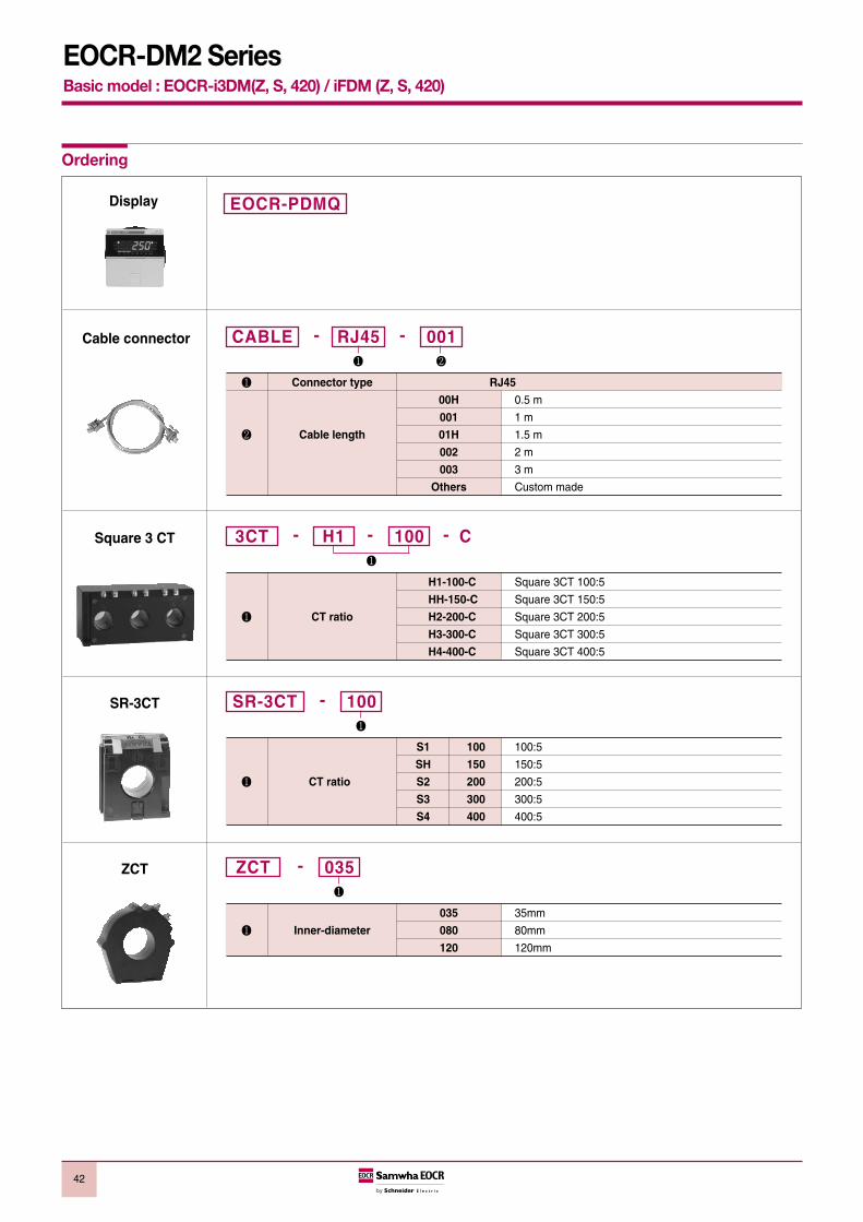
42
EOCR-DM2 Series Basic model : EOCR-i3DM(Z, S, 420) / iFDM (Z, S, 420)
Ordering
EOCR-PDMQDisplay
Cable connector
Connector type RJ45
00H 0.5 m
001 1 m
Cable length 01H 1.5 m
002 2 m
003 3 m
Others Custom made
RJ45 001CABLE - -
Square 3 CT
H1-100-C Square 3CT 100:5
HH-150-C Square 3CT 150:5
CT ratio H2-200-C Square 3CT 200:5
H3-300-C Square 3CT 300:5
H4-400-C Square 3CT 400:5
H1 1003CT - - - C
SR-3CT
S1 100 100:5
SH 150 150:5
CT ratio S2 200 200:5
S3 300 300:5
S4 400 400:5
100SR-3CT -
ZCT
035 35mm
Inner-diameter 080 80mm
120 120mm
035ZCT -

Memo
43

44
General information
26
28
29
23
27
Worldwide service networkDomestic awards Korea1985 The Presidential Prize of ‘85 National Invention Awards1986 The Ministerial Prize of National Invention Promotion Awards
The KYUNGHYANG Energy PrizeThe Ministerial Prize of Korea Electronics ExhibitionThe Golden Prize of ‘86 National Invention Awards
1989 The Order of Industrial Service MeritThe Grand Prix of ‘89 National Invention Awards
1990 The Bronze Prize of ‘91 National Invention Awards1991 The Venture Company of 19911994 The Electric Industry Development Prize of KOMA
The Order of Industry Service Merit1995 The Tower of Export1998 UN WIPO Prize1999 The Order of Industrial Service Merit2003. 11 The Premier Prize of SIEF2004. 11 The Premier Prize of Electrical Engineering Awards2006. 05 The Ministerial Prize of 41th National Invention Awards2007. 05 The Tower Prize of 42th National Invention Awards
International Awards1989 The Silver Medal of INPEX Pittsburgh1990 The Silver Medal of Geneva International Invention Award1992 The Golden Medal of De L’Invention De Paris1993 The Bronze Medal of Beijing International Award1998 The Golden Medal of IENA98. Germany
ASIA Korea
China
Japan
Taiwan
Hongkong
Vietnam
Philippines
Thailand
Singapore
Malaysia
Indonesia
Sri Lanka
India
Pakistan
U.A.E
Bahrain
Syria
Iran
OCEANIA Australia
New Zealand
EUROPE Switzerland
Turkey
Greece
Spain
AFRICA
AMERICA
Egypt
South Africa
제품인증현황표
DS1EGR
SS AR ST SP SE SE2 DS DS2 DZ EVRSDDR
PMR 3DD FD 3DZ FDZ 3DM FDM 3DE FDE DS3
FM PMZ420 PFZ
SSD CT ZCTApproved
CE
UL
KR
ABS
SEV
CCS
TUV
CSA
RINA
CCC
¨
Mexico
Brasil
USA
Peru

45
Technical information
Option-1. Looping (Protect smaller current by looping option)
Some motor size may require one-third or one-fourth of particular EOCR currentrange. These installations can be accommodated by looping the motor wire 2 or3 times through the integral current transformers of the EOCR. This reduces thenumber and type of relays inventoried for spare purposes. Each additional loopwill increase the current measured as indicated by the following chart.
Ordering option - 05 type of each model fitted to an external current transformercan achieve higher ampere ranges. (EOCR-3DM/3MZ/3M420/FDM/FMZ/FM420)
Option-2. External current transformer option(Ext. CT option protect bigger current)
05 Type
Looping Option
Current settingrange (A)
0.5 ~ 6 0.25 ~ 3 0.17 ~ 2
0.12 ~ 1.50.10 ~ 1.2
No. of passing (#)12345
No. of loops(#)
0 …1 …
2 34
05 type60 type
Ext. CT option
DIP SWsetting
056005050505
Current settingrange (A)0.5 ~ 10 5.0 ~ 60 10 ~ 12015 ~ 18020 ~ 24030 ~ 360
Current ratio of Ext. CT
NILNIL
100 : 5150 : 5200 : 5300 : 5
EOCR type table for 3 phase motor
Short-circuit current setting (Isc)
Starting current
Current
Current setting (Is)
Starting
In O-time mode, EOCR does not make a trip assensing current (In) over preset over-current (Is) is notkept during preset o-time
In case Short-circuit current is over thanpreset trip value, it trips at 0.05sec
(i3MS, iFMS)
Motor tripped by EOCR
Starting time (dt)
Normal running status
Time
Tripped status
O-TIME:When sensing currentexceeds the preset currentrange.EOCR trip after O-time
D-TIME:In starting period, it senses 5 to 8 timeof rated current but delays O-time tripmode due to preset D-time which allows normal running without trip during starting period.
Motor tripped by EOCR.Reset the motor after removing the cause of motor failure.
Preset currentsetting exceed
Preset currentsetting exceed
Alert signal output
Preset alertsetting exceed
Alert output signal comes out after waiting1sec as soon as running current exceeds presetAlert setting value. It checks the increment ofload in advance before a trip happens
Overload
Alert setting (As)
Normal running current (As)
1sec
EOCR setting platform / Motor running current
Single pass Double pass
EOCR typeand CT
0560
100:5150:5200:5300:5400:5500:5
0.5~10 5~60
10~12015~18020~24030~36040~48050~600
0.751122303775
- -
115304050
100- -
1.522375575
132190220
2305075
100175250300
4.84893
125160310440572
4.24984
121163263376424
3.64273
105141227325390
416507095
300- -
4255070
120240400
-
4255070
120240400400
Current settingrange
(Adjustable) [A]
Capacity of 3 phase motorAC220 [V] AC380/440 [V]
kW HP kW HP
Motor current [A]
AC220V AC380V AC440V
Cable size IEC []
AC220V AC380V AC440V

46
Technical information
Setting tips in definite TCC mode1. Over current threshold (OC) : Set the OC at the rating current of a motor. To protect
machine together, it is recommended to set at110~120% of the actual normal operating current.
2. Starting delay time (D-time) : Set an expected start-up time to reach the normal speedof load. If you do not know it, set to 15sec at first andstart-up the motor to measure the time to reach thenormal operation speed by monitoring the displayedcurrent and then change the time into 2 sec longer thanthe time measured. For a Y-D start, it’s better to set timelonger than the preset time of the timer by 2secminimum normally.
3. Operation time (O-time) : Set the trip delay time which activates and counts downunder a fault condition.
Setting tips in inverse or thermal inverse TCC mode1. Over current (OC) : Set the OC at the rating current of a motor.
2. Starting delay time (D-time) : Usually, set D-time to zero. With zero D-time, the coldcurve is applied before the load current cross down theOC, and then the hot curve is applied.If the start-up time is long and fast trip is required duringmotor running, set D-time to start-up time or longer. Inthis case, over current protection is blocked during thestart-up, and the hot curve is applied when D-timeexpires.Since thermal inverse has no relation with D-time, set D-time to zero when the thermal inverse is selected.
3. Operation time (O-time) : It has 30 curves of 1~30 which conforms to theIEC947-4-1 standard. The class value approximately equals to the time to tripunder 550% of overload by the cold curve characteristic.
Over current and time setting tips.

47
EOCR Setting Guide
This is a setting guide and advice for user’s reference only .
Conditions to be checked for the normal operation of EOCR .
1. Check the status of correct settings by pressing the UP/DN button in
sequence.
2. When you enter the menu and wait for 3 sec, it starts
countdown during the O-time setting. and display
with a trip to the output . This means EOCR is operating well.
3. Check all the sequence wiring if it is safe and correct .
4. After completion of the motor starting, check if the current display is
fine, When the %LED in the bar graph doesn’t show, it needs to
check if the operation current is too lower than the Oc setting value
by 65% and on the contrary, the %LED shows 100% (red LED lights
on), It is advised to check the Oc setting if the re-adjustment is
necessary.
5. If the motor starting isn’t completed but EOCR operates, refer to the
Troubleshooting guide first and contact customer care center if the
trouble isn’t cleared.
Basic model (3DM / FDM)
Password input is necessary to chage the setting value of
EOCR, if a password is memorized except 000.
If the password is set to 000, no password input is necessary
in “000” to enter the setting change mode. Please take
caution not to forget the password.No password function is
provided in 3DM2/FDM2, 3MZ2/FMZ2.
The default setting is a 3phase motor. The setting change
to is necessary for 1 phase motor.
Time current characteristic (TCC). the defaut setting is
tcc : dE (definite TCC).
The default setting is “non”, setting value is the primary
current with an external CT combination in this mode.
( Ex: in case of 200; 5, the setting is 200 )
If the control power or EOCR itself has a problem, the
motor stops with the output relay trip in the “FS: on” mode.
The default setting is.
For the application which motor rotation direction is
important , “rP: on” should be set .
“rP:oFF” setting doesn’t make a problem after completion
of the installation for the permanent stable application.
The default setting is “rP:oFF”.
It is recommended for “oc” to set at the rating current of
motor. Default setting is oc:5.0A .
It means a starting delay time setting for a motor start up
duration from the start of motor to the normal running
current. The start up duration depends on the inertia of
load. Therefore, it is recommended to set the time after
measuring the time and current by EOCR with the initial
set of D-time at 20 sec. For a Star-delta start, the longer
time by 2sec than the setting of Star-delta timer is
recommended. Default setting is 5 sec.
It means the overcurrent trip time in definite TCC, when
motor operating current (In) exceeds over current setting
(Is) during the ot setting time, EOCR trips. Default setting
is 5 sec. The advantage of definite TCC is that user is able
to set accurate time and current and lead a mechanical
protection of load together with motor protection.
This is a trip class(curve) setting in Inverse TCC or
Thermal inverse TCC. The trip time changes according to
the operating current inverse proportionally. Thermal
inverse TCC reflects the Heat capacity of motor based on
the current measurement.
It means under current (Dry Run) protection, If a level
switch has a problem in a submersible pump, It backs up
the level switch function from no water running of pump
and protect the motor from overheating. For the
machinery running with a belt (including conveyer), It
candetect a broken belt. The current setting should be
higher than rating no load current of motor for this function.
The default setting is “oFF” .
It is “uc” trip delay time setting . If you don’t set the “uc”
function (uc:oFF), “ut” setting doesn’t appear at the menu.
This memu is to determine “enable/disable” of PL (Phase
loss) funnction. If you set “Ph:1Ph” at the power phase
selection menu for a single phase power supply line, this
menu doesn’t appear automatically.
It is trip delay time setting for PL. The default setting is 2
sec. For single phase power line setting, it doesn’t appear
at the munu.
EOCR calculates the unbalance rate among three
phase currents. It trips after “Ubt” setting time under a
unbalanced condition. The default setting is “oFF”.
Locked Rotor protection during starting up a motor (Stall).
If a rotor of motor is locked during starting and keep the
current at higher than the “Sc” setting during D-time,
EOCR trips in 0.5sec after D-time. The default setting is
“Sc: 4”.
The setting value is a multiple of “oc” setting value. This
function operates under the Definite TCC condition.
It is disabled under the Inverse TCC setting generally. But
if you set D-time greater than zero in Inverse setting, Stall
operates when d-time expires.
EOCR Setting Guide

48
EOCR Setting Guide
Locked rotor protection during normal running of motor
(Jam). It is used to prevent a problem caused by rapid
load increae. The setting value is a multiple of “oc” setting
value. The trip delay time setting range is 0.2~10 sec.
Alarm setting by % of the overcurrent threshold (oc). The
output contact 07-08 makes a signal of A,F,H according to
the ALo setting.
Reset type setting mode. Reset method shows below.
Electrical Reset . EOCR resets by power cycle
of control power or ESC button. It can be used
for a remote reset which enables EOCR to reset
from a remote site.
Hand Reset (Manual Reset). EOCR can be
reset by ESC button only.
Auto Reset . The time setting range is up to 20
minutes (20n). The auto reset number. of times
is connected to the restart limitation setting
menu. If the number of restrat over the restart
limitation number. in the “rn” setting menu
during 30 minutes, EOCR doesn’t reset
anymore.
Restart limitation number. It prevent a motor from a
burning fail caused by many restarts during 30 minutes.
In case an emergency restart is necessary, put the setting
at “OFF” This function activates in Auto-Reset mode only.
Modbus slave (ID) address. It can be set at No. 1 ~ 247.
Setting for communication speed. Select one among
1.2kbps, 2.4kbps, 4.8kbps, 9.6kbps,19.2kbps, 38.4kbps.
Parity setting. Select one among odd, even, non. even
parity is displayed as “Eun”.
Communication loss checking menu. If EOCR does not
receive a data frame during “Lt” setting time, it displays an
error message. The setting range is OFF, 1~999 sec.
Total running hour. Time accumulation starts if there is a
minimum sensing current in the line up to 99,999 hours.
User can check it anytime but not allowed to erase it.
Display unit is 1 hour.
Running hour which user can set and erase the setting
value. If you set the Alert output type at the “ALo: to”, the
output contact 07-08 repeats close and open to give a
signal after the preset accumlated time elapsed.
Self EOCR Check. If you push SET button in this menu,
EOCR count time up 3sec and “ot” setting time and
displays “End” with the output contact trip. This means
EOCR is operating well. This function is blocked during
motor running.
Additional menu (i3MS/iFMS)
Short Circuit protection. Setting value is a multiple of “oc”
set value.
Default setting is 10 times of “oc” setting.
Short Circuit trip delay time during motor starting to
prevent a trip caused by starting current.”OFF” setting is
possible .
Additional Menu (i3MZ/iFMZ, 3MZ2/FMZ2)
Earth leakage protection current setting. The default
setting is 0.5A. Minimum setting value is recommeded, if
there is no leakage current in the motor by the current
display. If the display shows a leakage current more than
50mA, user must check the insulation of motor and line. In
the case of installing EOCR at the secondary side of
Inverter, it’s better to take care of EOCR opreration error
due to harmonics of Inverter.
Earth leakage trip time. The default setting is “0.05sec”.
It is recommended to set the faster time and lower current
than the earth fault protection relay in the upper power
system.
Earth leakage trip delay time during motor starting to
prevent a trip caused by a stray current and harmonics of
the starting current in motor.
Additional menu (i3M420/iFM420)
Current range setting menu of 4~20mA analog output
signal. The setting value corresponds to the max analog
output (20mA). The setting value can be made
independently from “oc” setting .
Analog output current formula :
Where, CTR is the parameter for CT, i.e. in case of CI :
non, it is 1. I is the measured average lond current.
If the load current is equal or greater than this value,
analog output is fixed to 20mA . For the current lower than
minimun sensing current of EOCR(0.4A), the analog
output signal gives 4 mA .
EOCR Setting Guide
mA =Ⅰ× 16 + 4
rS
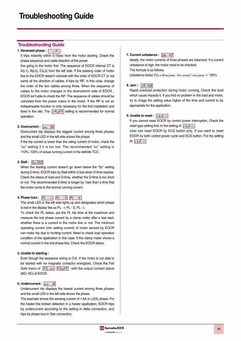
49
Troubleshooting Guide
1. Reversed phase :It trips instantly within 0.15sec from the motor starting. Check the
phase sequence and cable direction of the power
line going to the motor first. The sequence of EOCR internal CT is
A(L1), B(L2), C(L3) from the left side. If the passing order of motor
line to the EOCR doesn’t coincide with the order of EOCR CT or not
same all the direction of cables, It trips by RP. In this case, change
the order of the two cables among three. When the sequence of
cables to the motor changes in the downstrenm side of EOCR ,
EOCR isn’t able to check the RP. The sequence of cables should be
coincided from the power mains to the motor. If the RP is not an
indispensable function or only necessary for the first installation and
fixed in the site, The setting is recommended for normal
operation.
2. Overcurrent : Overcurrent trip displays the biggest current among three phases
and the small LED in the left side shows the phase.
If the trip current is lower than the rating current of motor, check the
“oc” setting if it is too low. The recommended “oc” setting is
110%~120% of actual running current in the definite TCC.
3. Stall : When the starting current doesn’t go down below the “Sc” setting
during D-time. EOCR trips by Stall within 0.5se when D-time expires.
Check the status of load and D-time, whether the D-time is too short
or not. The recommended D-time is longer by 1sec than a time that
the motor come to the normal running current .
4. Phase loss : The small LED in the left side lights up and designates which phase
is lost in the display like as PL - r, PL - S, PL - t,
To check the PL status, put the PL trip time at the maximum and
measure the lost phase current by a clamp meter after a test start,
whether there is a current in the motor line or not. The minimum
operating current (min setting current) of motor sensed by EOCR
can make trip due to hunting current. Need to check load operation
condition of the application in this case. If the clamp meter shows a
normal current in the lost phase line, Check the EOCR status.
5. Unable to starting :Even though the sequence wiring is O.K. If the motor is not able to
be started with no magnetic contactor energized, Check the Fail
Safe menu of with the output contact status
(NO, NC) of EOCR .
6. Undercurrent :Undercurrent trip displays the lowest current among three phases
and the small LED in the left side shows the phase.
The example shows the sensing current of 1.6A in L2(S) phase. For
the heater line broken detection in a heater application. EOCR trips
by undercurrent according to the setting in delta connection, and
trips by phase loss in Star connection.
7. Current unbalance : Ideally, the motor currents of three phases are balanced. If a current
unbalance is high, the motor need to be checked.
The formula is as follows.
Unbalance factor (%) = (Imax phase - Imin_phase) / Imax_phase× 100%
8. Jam : Rapid overload protection during motor running, Check the load
which cause impacts it. If you find no problem in the load and motor,
try to chage the setting value higher of the time and current to be
appropriate for the application.
9. Unable to reset : If you cannot reset EOCR by control power interruption, Check the
reset type setting first. In the setting of
User can reset EOCR by ECS button only. If you want to reset
EOCR by both control power cycle and ECS button, Put the setting
at
Troubleshooting Guide

50
Communication setting valuePlease set the Modbus communication parameters by PCON or HMI for the communication. Slave addressBaud rateParityCommunication loss timeout
Slave addressThe EOCR has slave addresses from 1 to 247. The factory default setting is 1.
Baud rateThe Communication speed provided is like below.1.2kbps2.4kbps4.8kbps9.6kbps19.2kbps38.4kbpsThe factory default setting is 19.2kbps
Parity settingEvenOddNoneThe factory default setting is even. Please refer to the table for the stop bit setting.
Communication loss timeoutIt is the criteria to confirm the communication disconnection with a master like as PLC. EOCR judges it as a communication disconnection error, if there is no call from the masterduring a certain preset time. The time setting range is 1~999sec the factory default setting is OFF. The OFF means nocommunication error check. It is advised to set it at OFF, if there is no concern ofcommunication disconnection or no needs of communication error check at ordinary times.
Modbus network setting
Parity setting Stop bit
Even or Odd 1
None 2
RS485 bus connectionRS485 standard allows several different characteristics.PolarizationLine terminatorNumber of slavesLength of the busThere is a definition of Modbus presented in detail at the website of Modbus.org in 2002.Standard connection
Communication Guide

5151
Communication Guide
The standard connection conforms to the Modbus specifications, sepecially 2 wiremultidrop serial bus diagram, presented at the website of Modbus.org in 2002(Modbus_over_serial_line_V1.pdf, Nov.2002). Simple wiring diagram is like below.
The characteristics is like below in case of a direct connection to the bus.
Items Contents
Type of trunk cablesingle, shielded, twisted pair cable.
Min 3rd cable
Maximum length of the bus 1000m (3,2181 ft) (at 19.2kbps)
Maximum number of32 stations (31 slaves)
stations without repeater
20m (66ft, at 1 tapoff)
Maximum length of tapoffs 40m (131ft, divided by tapoff no.
in Multi-Junction Box)
450 - 650Ω Pullup resistor, 5V basis
450 - 650Ω Pulldown resistor,
Bus polarization Recommend the polarization to Master at
Common. There is no polarization at
RS485 of EOCR .
Line terminator 120Ω Resistor, + /- 5%
Common polarityYES (connect 1 protection ground minimum
to the bus)
Standard connection

52
Communication Guide
Bus connection through a SCA type junction box
1. Master (PLC, PC or communication module)
2. Modbus cable (It is different according to the master side or a master having polarization combined to the other part of Bus)
3. Junction box
4. Modbus cable
5. Line terminators : 120Ω - 0.25W
Please use a cable with 2pair shieded twisted conductors for Interface protection. It is adviced to isolate the Modbus cable 30cm(11.8in) at least from a power cable. If necessary, intersect the Modbus cable to a power cable perpendicularly. Refer to the diagram in the left side for the line terminator wiring.


EO
CR
CA
T_E
N
2008
Sam
wha
EO
CR
Ltd
.-A
ll rig
hts
rese
rved
.
Digital Electronic O
ver Current R
elays
Head Office6th floor, Jeil Bldg., 94-46, Youngdeungpo-Dong 7Ka, Youngdeungpo-Ku, Seoul, KoreaTel. 82 2 3473 2340 / Fax 82 2 3473 1159Iksan Plant574, Yongie-dong, Iksan-shi, Junbuk, KoreaTel. 82 63 835 5033 / Fax 82 63 835 4175www.eocr.com 11/2008

![[ 3000 Series Time Delay Relays and Measuring Relays ... · [ 3000 Series Time Delay Relays and Measuring Relays ] ... Measuring Relays ] • Time Delay Relays ... Dear Reader, Dear](https://img.dokumen.tips/doc/110x75/5b85683b7f8b9aec488e43dd/-3000-series-time-delay-relays-and-measuring-relays-3000-series-time.jpg)