Embed Size (px)
Citation preview
2/4
Presentation of the rangeThe RSB interface relay range comprises: 1 12 A relays with 1 CO contact , 16 A relays with 1 CO contact, and 8 A relays with 2
CO contacts2 Sockets with separate contact terminals3 Protection modules (diode, diode + LED, RC circuit, or varistor + LED) common to
all sockets4 A plastic maintaining clamp for all sockets5 Clip-in legend for all sockets
Socket descriptionSockets with separate contact terminals (1)
1 Connection by connector2 5 or 8 female contacts for the relay pins3 Hole for panel mounting4 Location for protection modules5 Locking components for plastic maintaining clamp6 Locating slot for mounting on DIN rail
(1) The inputs and outputs are separate from the relay supply .
Zelio Relay - Electromechanical relaysPlug-in relaysRSB interface relays
Presentation
1
2
35
6
4
Inputs
Outputs
Relay supply
5
4
1
2
3
1
2
3
4
5
6
7
8
9
10

2/5
Zelio Relay - Electromechanical relaysPlug-in relaysRSB interface relays
References
Relays for standard applicationsControl circuit voltage
Sold in lots of
Number and type of contacts - Thermal current (Ith)1 CO - 12 A 1 CO - 16 A 2 CO - 8 AUnit reference (1)
Unit reference (1)
Unit reference (1)
Weight
V kg/lbc 6 10 RSB1A120RD RSB1A160RD RSB2A080RD 0.014/0 .031
c 12 10 RSB1A120JD RSB1A160JD RSB2A080JD 0.014/0 .031
c 24 10 RSB1A120BD RSB1A160BD RSB2A080BD 0.014/0 .031
c 48 10 RSB1A120ED RSB1A160ED RSB2A080ED 0.014/0 .031
c 60 10 RSB1A120ND RSB1A160ND RSB2A080ND 0.014/0 .031
c 110 10 RSB1A120FD RSB1A160FD RSB2A080FD 0.014/0 .031
a 24 10 RSB1A120B7 RSB1A160B7 RSB2A080B7 0.014/0 .031
a 48 10 RSB1A120E7 RSB1A160E7 RSB2A080E7 0.014/0 .031
a 120 10 RSB1A120F7 RSB1A160F7 RSB2A080F7 0.014/0 .031
a 220 10 RSB1A120M7 RSB1A160M7 RSB2A080M7 0.014/0 .031
a 230 10 RSB1A120P7 RSB1A160P7 RSB2A080P7 0.014/0 .031
a 240 10 RSB1A120U7 RSB1A160U7 RSB2A080U7 0.014/0 .031
Sockets with separate contact terminal arrangement and connector connectionRated insulation voltage
Thermal current (Ith)
Relay type Sold in lots of
Unit reference
Weightkg/lb
a 250 V 12 A RSB1A120pp 10 RSZE1S35M 0.060/0 .13210 A (2) RSB1A160pp (3)
RSB2A080pp10 RSZE1S48M 0.050/0 .110
Protection modulesDescription For
use withVoltage Sold in
lots ofUnit reference
Weight
V kg/lbDiode All sockets c 6…230 10 RZM040W 0.003/0 .007
RC circuit All sockets a 24…60 10 RZM041BN7 0.010/0 .022a 110…240 10 RZM041FU7 0.010/0 .022
Diode + green LED All sockets c 6…24 10 RZM031RB 0.004/0 .009c 24…60 10 RZM031BN 0.004/0 .009c 110…230 10 RZM031FPD 0.004/0 .009
Varistor + green LED All sockets c or a 6…24 10 RZM021RB 0.005/0 .011c or a 24…60 10 RZM021BN 0.005/0 .011c or a 110…230 10 RZM021FP 0.005/0 .011
AccessoriesDescription For
use withSold in lots of
Unit reference
Weightkg/lb
Plastic maintaining clamp All sockets 10 RSZR215 0.002/0 .004Legend All sockets 10 RSZL300 0.001/0 .002
(1) To order a relay complete with socket (sold in lots of 20), add the suffix S to one of the following voltage codes: JD, BD, B7, P7, or F7 . Example: RSB2A080BD + RSZE1S48M becomes RSB2A080BDS .
(2) RSZE1S48M is a two terminal socket each carrying 10 A .(3) If RSZE1S48M socket terminals are linked, relay RSB1A160pp can be used up to 16 A . See “Wiring diagrams” on
www .schneider-electric .com .
PF1
5363
6A
RSB1A120JD + RZM031FPD + RSZE1S35M
PF1
5364
6A
RSB1A160JD + RSZE1S48M
RSZR215
PF5
1456
5
1
2
3
4
5
6
7
8
9
10
2/24
Technical presentation
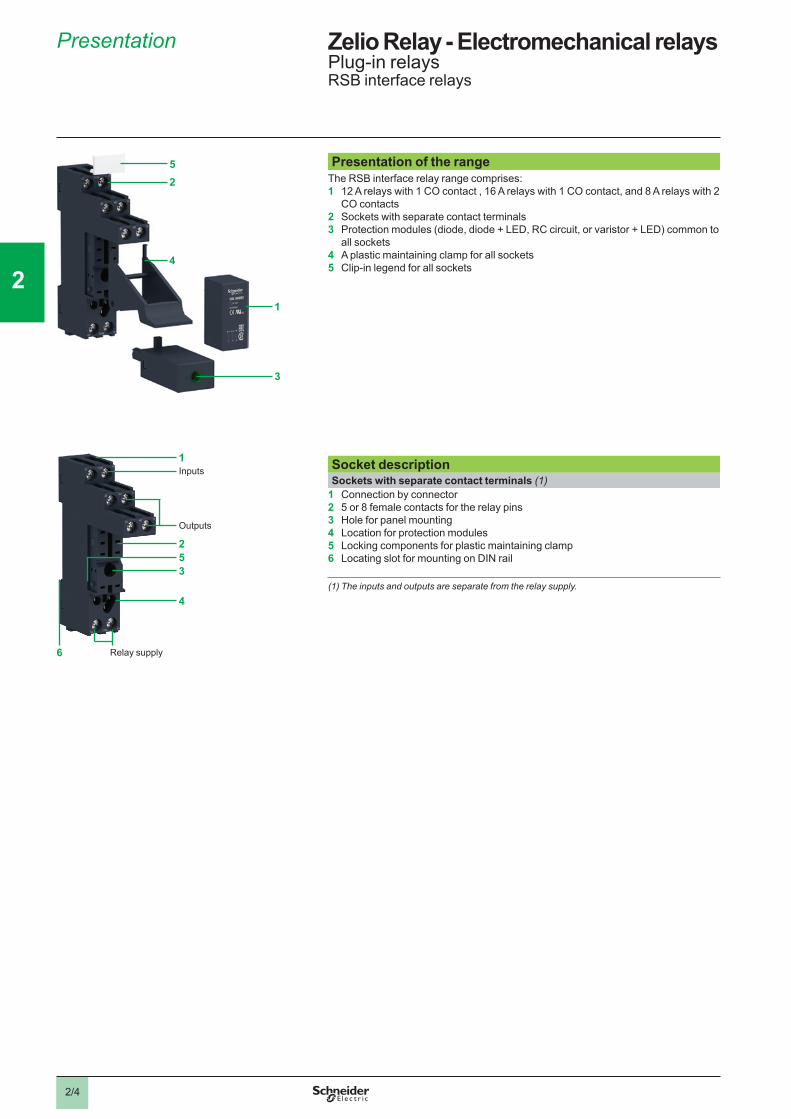
RelaysContact typesSymbol Configuration EU USA
Make contact (Normally Open)
NO SPST-NODPST-NOnPST-NO (1)
Break contact (Normally Closed)
NC SPST-NCDPST-NCnPST-NC (1)
Changeover Contact CO SPDTDPDTnPDT (1)
Utilization categoriesCategory Type of current Applications
AC-1 a 1-phasea 3-phase
Resistive or slightly inductive loads
AC-3 a 3-phase Starting and braking of squirrel cage motors; reversing direction of rotation only after stopping of motor
AC-4 a 3-phase Starting of squirrel cage motors, inching; plugging, reversing direction of rotation
DC-1 c Resistive or slightly inductive loads (2)
AC-14 a 1-phase Control of electromagnetic loads (< 72 VA), auxiliary control relays, power contactors, electromagnetic solenoid valves, and electromagnets
AC-15 a 1-phase Control of electromagnetic loads (> 72 VA), auxiliary control relays, power contactors, electromagnetic solenoid valves, and electromagnets
DC-13 c Control of electromagnetic loads, auxiliary control relays, power contactors, magnetic solenoid valves, and electromagnets
Protection categoriesCategory Explanation Condition
RT 0 Unenclosed relay Relay not provided with a protective case
RT I Dust protected relay
Relay provided with a case that helps to protect its mechanism from dust
RT II Flux-proof relay Relay capable of being automatically soldered without allowing the migration of solder fluxes beyond the intended areas
RT III Wash-tight relay Relay capable of being automatically soldered and then washed to remove flux residues and minimize the possibility of ingress of flux or washing solvents
RT IV Sealed relay Relay provided with a case that has no venting to the outside atmosphere
RT V Hermetically sealed relay
Sealed relay with an enhanced level of sealing
(1) n = number of contacts .(2) The switchable voltage can be doubled, for an equal current, by connecting 2 contacts in
series .
Zelio Relay - Electromechanical relaysPlug-in relays
1
2
3
4
5
6
7
8
9
10
2/25
Technical presentation (continued)
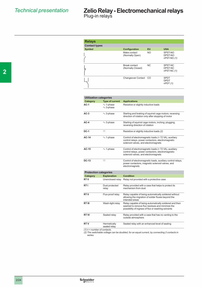
Protection modulesWhenever an inductive load is de-energized (coil of a relay or of a contactor), an overvoltage appears at its terminals. This voltage peak can reach several thousand volts and a frequency of several MHz.It is likely to disturb the operation of automation systems that contain electronic devices.Protection modules are used to reduce the voltage peak on de-energization and therefore limit the energy of interference signals to a level that will not disturb surrounding coils and electronic devices.
These modules are used to help reduce the risk of:v electromagnetic compatibility problemsv deterioration of contact materialsv damage to insulation due to overvoltagev damage to electronic components
Diode protection module (with or without LED)
Coil voltage with diode protection module (c only)
b Advantagesv accumulation of energy allowing current to flow in the same directionv absence of any voltage peaks at the coil terminalsv low cost
b Disadvantagesv increase in relay drop-out time (3 to 4 times the usual time)v no polarity protectionv de-energization of the relay
Protection module with varistor
Coil voltage with varistor protection module (a and c)
b Advantagesv can be used with a and c supplyv voltage peak limited to about 2 Unv little effect on relay drop-out time
b Disadvantagesv no modification of coil’s own oscillating frequencyv limitation of switching frequency
Protection module with RC circuit
Coil voltage with RC circuit protection module (a only)
S1 = S2 = Energy released
b Advantagesv coil oscillating frequency reduced to about 150 Hzv voltage peak limited to 3 Unv little effect on relay drop-out time
b Disadvantagesv no protection for low voltages
U
t
Supply voltage
Energy released
Break
U
t
Energy released
Break
Lim
itatio
n of
vol
tage
pe
aks
S1
U1
U2
U
t
Break
S2 (with RC)
Zelio Relay - Electromechanical relaysPlug-in relays
1
2
3
4
5
6
7
8
9
10