Embed Size (px)
Citation preview

Digital Control ConceptsDigital Control ConceptsFor Power Supply EngineersFor Power Supply EngineersRobert V. WhiteStaff EngineerWorldwide Technology Group

Presentation OverviewPresentation OverviewPresentation Overview
Control Techniques– Traditional Analog– Traditional Digital– Modern Digital
Examples Of Digital Advantages– Dead Time Optimization– Automatic Compensation Tuning
Digital Control ≠ Digital Power Management

Analog PWMAnalog PWMAnalog PWM
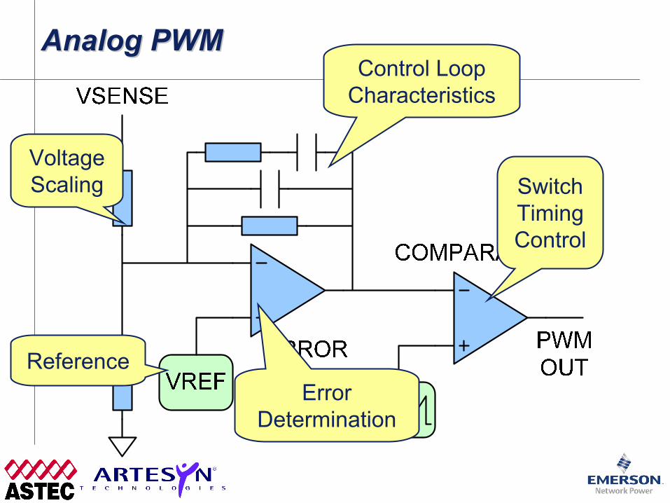
Analog PWMAnalog PWMAnalog PWM
VoltageScaling
ErrorDetermination
Control LoopCharacteristics
SwitchTimingControl
Reference

Classical Digital PWMClassical Digital PWMClassical Digital PWM

Classical Digital PWMClassical Digital PWMClassical Digital PWM
Resolution+ Accuracy +
Speed =$$$
Typical DSP/Processor=> Lots Of MIPs
=> $$$
Counter Approach+ High Precision
= Very Fast Clock= $$$

Re-Thinking Digital Control For PowerReRe--Thinking Digital Control For PowerThinking Digital Control For Power

Step 1: Digitize Only The ErrorStep 1: Digitize Only The ErrorStep 1: Digitize Only The Error

Step 1: Digitize Only The ErrorStep 1: Digitize Only The ErrorStep 1: Digitize Only The Error
How Many Bits Are Needed?
3? 5? 7?

Thinking About Error BinsThinking About Error BinsThinking About Error Bins
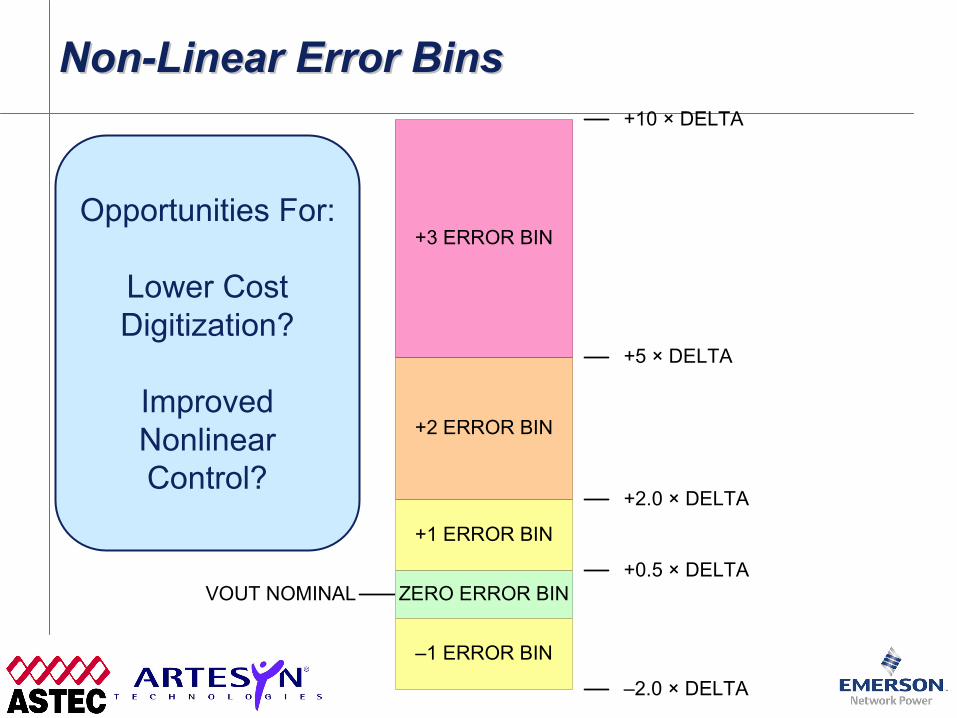
Non-Linear Error BinsNonNon--Linear Error BinsLinear Error Bins
VOUT NOMINAL ZERO ERROR BIN+0.5 × DELTA
+1 ERROR BIN
+2 ERROR BIN
+3 ERROR BIN
+2.0 × DELTA
+5 × DELTA
+10 × DELTA
–1 ERROR BIN
–2.0 × DELTA
Opportunities For:
Lower CostDigitization?
ImprovedNonlinearControl?

Step 2: Simplify Calculation EngineStep 2: Simplify Calculation EngineStep 2: Simplify Calculation Engine
Lookup Table,Fixed Configuration Filters,
State Machines
$10DSP
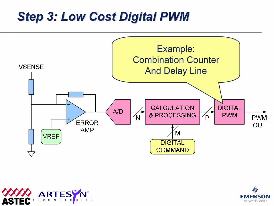
Step 3: Low Cost Digital PWMStep 3: Low Cost Digital PWMStep 3: Low Cost Digital PWM
Example:Combination Counter
And Delay Line
The Point?Re-Thinking Digital
Control ForPower ConversionIs Lowering Cost
And Simplifying Design

Avoiding Limit CyclingAvoiding Limit CyclingAvoiding Limit Cycling
ZERO ERROR BIN
+1 ERROR BIN
–1 ERROR BIN
+2 ERROR BIN
–2 ERROR BIN
+3 ERROR BIN
–3 ERROR BIN
OUTPUT VOLTAGED/A ERROR BINS
COARSE RESOLUTION DPWMPOSSIBLE OUTPUT VOLTAGES

Avoiding Limit CyclingAvoiding Limit CyclingAvoiding Limit Cycling
VOUTNOMINAL
DUTYCYCLE
N
N+1
PWM
Avoiding Limit CyclingAvoiding Limit CyclingAvoiding Limit Cycling
ZERO ERROR BIN
+1 ERROR BIN
–1 ERROR BIN
+2 ERROR BIN
–2 ERROR BIN
+3 ERROR BIN
–3 ERROR BIN
OUTPUT VOLTAGED/A ERROR BINS
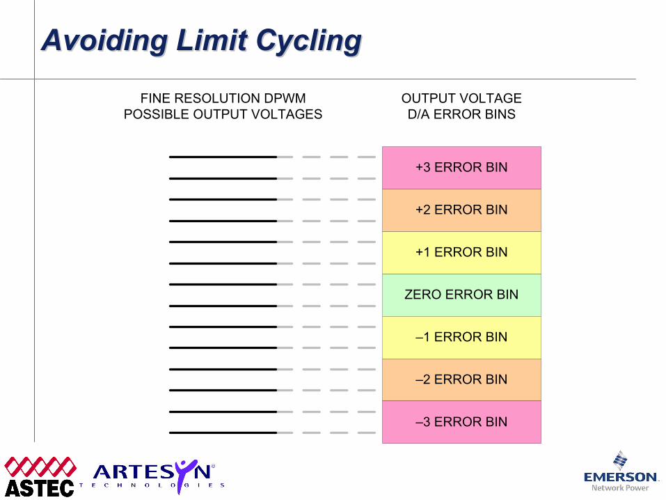
FINE RESOLUTION DPWMPOSSIBLE OUTPUT VOLTAGES
Avoiding Limit CyclingAvoiding Limit CyclingAvoiding Limit Cycling
ZERO ERROR BIN
+1 ERROR BIN
–1 ERROR BIN
+2 ERROR BIN
–2 ERROR BIN
+3 ERROR BIN
–3 ERROR BIN
OUTPUT VOLTAGED/A ERROR BINS
FINE RESOLUTION DPWMPOSSIBLE OUTPUT VOLTAGES
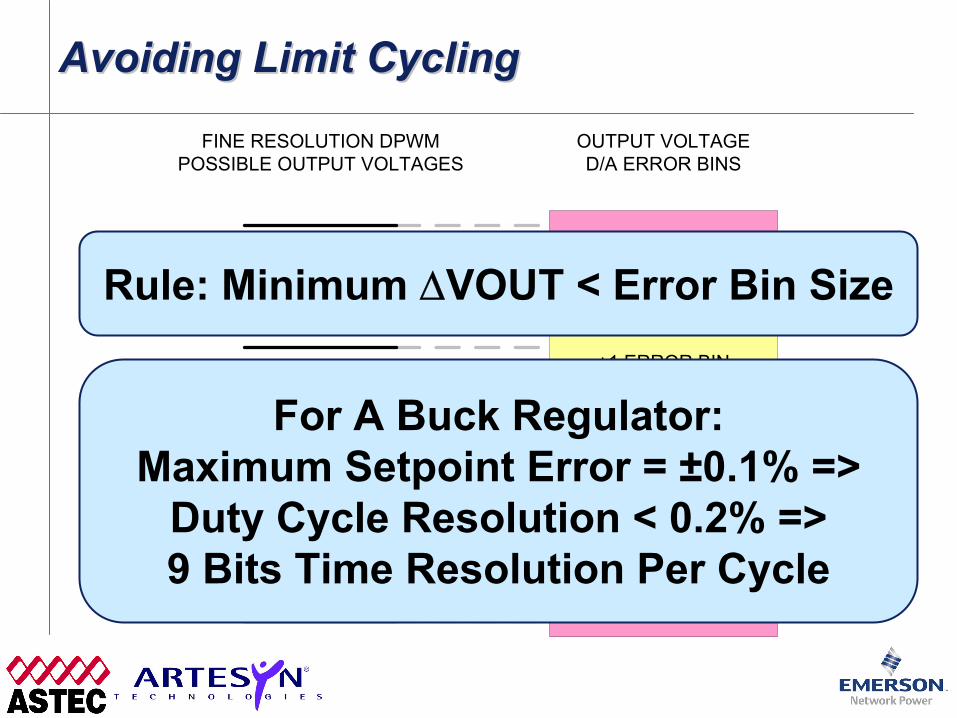
Rule: Minimum ΔVOUT < Error Bin Size
For A Buck Regulator:Maximum Setpoint Error = ±0.1% =>
Duty Cycle Resolution < 0.2% =>9 Bits Time Resolution Per Cycle

Sampling the OutputSampling the OutputSampling the Output
Once Per Cycle Can GiveGood Information On Average Value
Oversampling Is NotNecessarily Helpful
ComputationTime!
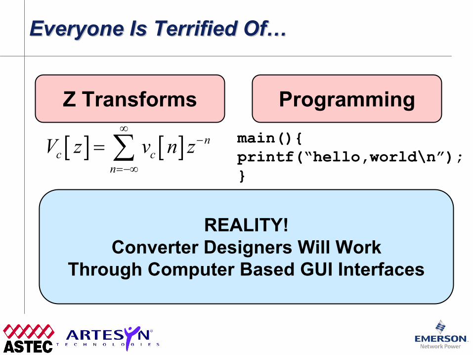
Everyone Is Terrified Of…Everyone Is Terrified Of…Everyone Is Terrified Of…
Z Transforms Programming
[ ] [ ] nc c
nV z v n z
∞−
=−∞
= ∑ main(){printf(“hello,world\n”);}
REALITY!Converter Designers Will Work
Through Computer Based GUI Interfaces

Winning Application #1:Efficiency OptimizationWinning Application #1:Winning Application #1:Efficiency OptimizationEfficiency Optimization
Digital Control Offers Opportunities To Optimize Operation To Minimize LossesExample: Buck Converter Dead Time (CoPEC)– Start With Excessive Deadtime– Slowly Minimize While Watching Duty Cycle– Minimum Duty Cycle => Minimum Losses
Example: On Bus Voltage– Monitor Load Of POLs Powering A Board– Light Load? Lower Bus Voltage– Heavy Load? Increase Bus Voltage
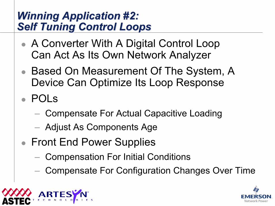
Winning Application #2:Self Tuning Control LoopsWinning Application #2:Winning Application #2:Self Tuning Control LoopsSelf Tuning Control Loops
A Converter With A Digital Control LoopCan Act As Its Own Network AnalyzerBased On Measurement Of The System, A Device Can Optimize Its Loop ResponsePOLs– Compensate For Actual Capacitive Loading– Adjust As Components Age
Front End Power Supplies– Compensation For Initial Conditions– Compensate For Configuration Changes Over Time

Winning Application #3:Digital Power ManagementWinning Application #3:Winning Application #3:Digital Power ManagementDigital Power Management
Digital Control ≠ Digital Power Management– But They Marry Very Well!– Passing Digital Values From User’s GUI
Directly To A Digital Control Loop WillSimplify IC Design And Lower Cost
Improved Fault Management– Digital Control Enables Graceful Transition
Between Normal And Abnormal Operating Modes

References – For More InformationReferences References –– For More InformationFor More Information
Colorado Power Electronics Center (CoPEC)– In My Opinion, Leading The Way In Digital Control
And Silicon Integration Research Useful To Industry– Much Of This Presentation Based On Their Work– http://ece-www.colorado.edu/~pwrelect/
Seth Sanders/UC Berkeley– Limit Cycling Paper Is Classic– http://www-power.eecs.berkeley.edu/sanders.html