Embed Size (px)
DESCRIPTION
ytriytr
Citation preview

embedded LCD-DISPLAY240x128 WITH INTELLIGENCE
Issue 04.2012
Zeppelinstraße 19 · D-82205 Gilching · Phone +49-(0)8105-778090 · Fax +49-(0)8105-778099 · www.lcd-module.de · [email protected]
TECHNICAL DATA* LCD GRAPHICS DISPLAY WITH A RANGE OF GRAPHICS FUNCTIONS* 8 BUILT-IN SOFT-FONTS* FONT ZOOM FROM approx. 2mm TO approx. 50mm, also ROTATED BY 90°* 3 DIFFERENT ONBOARD INTERFACES: RS-232, I²C BUS OR SPI BUS* 240x128 PIXELS WITH LED BACKLIGHT, BLUE NEGATIVE OR* BLACK&WHITE POSITIVE, FSTN TECHNOLOGY OR AMBER* POWER SUPPLY +5V@ TYPICAL 75mA / 210mA (WITHOUT / WITH LED BACKLIGHT)* POSITIONING ACCURATE TO THE PIXEL WITH ALL FUNCTIONS* STRAIGHT LINE, POINT, AREA, AND/OR/EXOR, BAR GRAPH...* CLIPBOARD FUNCTIONS, PULL-DOWN MENUS* UP TO 256 IMAGES STORABLE INTERNALLY* UP TO 256 MACROS PROGRAMMABLE (32 kB EEPROM ONBOARD)* COMBINATIONS OF TEXT AND GRAPHICS, FLASHING ATTRIBUTES: ON/OFF/INVERTED* BACKLIGHT CAN BE SWITCHED BY SOFTWARE* ANALOG TOUCH PANEL: VARIABLE GRID* FREELY DEFINABLE KEYS AND SWITCHES
Dimension:113x70x12mm
ORDERING CODESDISPLAYS240x128 DOTS, WHITE LED-BACKLIGHT, BLUENEGATIVE EA eDIP240B-7LWAS ABOVE, BUT WITH TOUCH PANEL EA eDIP240B-7LWTP240x128 DOTS, WHITE LED-BACKLIGHT, POSITIVE MODE, FSTN EA eDIP240J-7LWAS ABOVE, BUT WITH TOUCH PANEL EA eDIP240J-7LWTP240x128 DOTS, WHITE LED-BACKLIGHT, POSITIVE MODE, FSTN EA eDIP240J-7LAAS ABOVE, BUT WITH TOUCH PANEL EA eDIP240J-7LATPSTARTERKITINCLUDES EA eDIP240B-7LWP AND EVALUATION BOARD WITH USBFOR DIRECT CONNECTION TO PC AND INTERFACE BOARDS FORCONNECTION WITH YOUR HOST SYSTEM EA EVALeDIP240BAS ABOVE, BUT WITH EA eDIP240J-7LWTP EA EVALeDIP240JADDTIOTNAL PARTSMOUNTING BEZEL (ALUMINIUM), BLACK ANODIZED EA 0FP241-7SWSOCKET 1x20, 4.5mm HIGH (1 piece) EA B254-20

EA eDIP240-7Page 2
Specifications may be changed withoutprior notice. Printing error reserved
CONTENTS
GENERAL ..................................................................................................................... 3
ELECTRICAL SPECIFICATIONS...................................................................................4
RS-232.......................................................................................................................... 5
SPI ................................................................................................................................6
I²C ................................................................................................................................7
SOFTWARE PROTOCOL ............................................................................................ 8-9
TOUCH PANEL ............................................................................................................ 10
CHARACTER SETS .................................................................................................. 11-12
COMMANDS / FUNCTIONS IN TABULAR FORM ..................................................... 13-15
ACKNOWLEDGEMENTS FROM THE CONTROL PANEL............................................. 16
PROGRAMMING EXAMPLE ........................................................................................ 17
PROGRAMMING MACROS ...................................................................................... 18-19
DIMENSIONS .............................................................................................................. 20
Documentation of revision
Date Type Old New Reason / Description
15.02.04 V1.0 Preliminary version
24.11.04 V1.1--Modulo 8
New Command Macro-Process #MD../#MZ../#MS..Adaptor MAX232 circuit diagrammModulo 256
new firmware-typing error in protocol description
18.01.05 V1.2 New Command Terminal-Cursor Save/Restore #TS/#TRNew Command Bargraph send continous #AQ 2
new firmware
07.04.05 V1.3New addressable 2-wire RS485 Interface with SN75176New 32 additional I2C AddressesNew Commands #AG, #SI, #KA
new firmware
13.05.05 V1.4 Bugfix in SPI- I2C-Mode after wrong Packet (NAK) new firmware
04.10.05 V1.5some problems with opertating >60°C (display corrupted)New Protocoll Info Command 'DC2 1 P bcc'Bugfix in #GZ (pointsize), #B RLOU (typ2+3 linewitdh)
new firmware
18.10.05 V1.6 OUT-port functionality on not used configuration pins new firmware
17.02.06 - Drawing for mounting panel EA 0FP241-7SW included -
27.04.06 - V/A 61.0mm Revised drawing (V/A = 60.4mm and pcb Rev.D)
29.06.07 - Insert EA eDIP240J-7LA

EA eDIP240-7Page 3
Specifications may be changed withoutprior notice. Printing error reserved
GENERALThe EA eDIP240-7 is the world’s first display with integrated intelligence! As well as a number of built-in fontswhich can be used with pixel accuracy it also features a whole range of sophisticated graphics functions.Supplied with 5V, the display is ready for operation immediately. It is controlled via one of the 3 integrated RS-232, SPI or I²C interfaces.Graphics commands similar to high-level languages are used for programming. There is no longer any needfor the time-consuming programming of character sets and graphics routines. The ease of use of this displaywith its touch panel reduces development time dramatically.
HARDWAREThe display is designed to work with an operating voltage of +5V. Data transfer is either serial andasynchronous using the RS-232 format or synchronous using the SPI or I²C specification. A simple protocolis used for all data transfer variants to improve data reliability.
ANALOG TOUCH PANELThe EA eDIP240B-7LWTP and EA eDIP240J-7LWTP versions are equipped with an integrated touch panel.You can make entries and menu or bar graph settings by touching the display. The labeling of the “keys” isflexible and can also be changed during runtime (different languages, icons). The drawing of the individual“keys” and the labeling is handled by the integrated software.
LED BACKLIGHT, TYPES B AND JAll displays in blue-and-white (B) and black-and-white (J) are equipped with a modern, low power consumptionLED backlight. Whereas the black&white and the amber-colored display can still be read even when thebacklight is switched off completely, the blue-white display requires a minimum level of illumination to be legible.The backlight can be switched off with a software command and the brightness can be adjusted.We recommend the black&white version for use in direct sunlight. For all other applications, we recommendthe high-contrast, blue-white version.Note that the white LED backlight is subject to aging. That means switching off or dimming backlight is a mustfor 24-hour-applications. Not so for the amber backlight.
SOFTWAREThe display is programmed by means of commands, such as Draw a rectangle from (0,0) to (64,15). Noadditional software or drivers are required. Strings can be placed with pixel accuracy. Flashing attributes canbe assigned as often as you like – for graphics as well. Text and graphics can be combined at any time. Upto 16 different character sets can be used. Each one can be zoomed from 2 to 4 times. With the largestcharacter set, the words and numbers displayed will fill the screen.
ACCESSORIESEvaluation-Board (Programmer) for internal data flash memoryThe display is shipped fully programmed and with all fonts. The additional Evaluation-Board is thusgenerally not required.However, if the internal character sets have to be changed or extended, or if images or macros haveto be stored internally, the Evaluation-Board EA 9777-2USB, which is available as an accessory, willburn the data/images you have created into the on-board EEPROM (32/64 kB) permanently.The Evaluation-Board runs under Windows and is connected to the PC’s USB interface. It is shippedwith an interface cable and the installation software. The Evaluation-Board is equipped with serveralLEDs, pushbottons and potentiometer to test all peripherial modes of the eDIP.Interface-Expansion for Evaluation-Board (included in the Starter-Kit):Wtih the expansion EA 9777-2PE for the Evaluation-Board all interfaces of the display are madeavailable with the help from small adapter boards: RS-232, RS-485, SPI, I²C, RS-232 (CMOS level).Further information you will find in the datasheet of the Evalution-Board.

EA eDIP240-7Page 4
Specifications may be changed withoutprior notice. Printing error reserved
SPEZIFICATION AND CHARACTERISTICS
Characteristics
Value Condition min. typ. max. Unit
OperatingTemperature
-20 +70 °C
Storage Temperature -30 +80 °C
Storage Humidity < 40°C 90 %RH
Operating Voltage 4.5 5.0 5.5 V
Input Low Voltage -0.5 0.2*VDD V
Input High Voltage Pin Reset only 0.9*VDD VDD+0.5 V
Input High Voltage except Reset 0.6*VDD VDD+0.5 V
Input Leakage Current Pin MOSI only 1 uA
Input Pull-up Resistor 20 50 kOhms
Output Low Voltage 0.7 V
Output High Voltage 4.0 V
Output Current 20 mA
CurrentBacklight off 75 mA
Backlight on 210 mA
OUTPUTBeginning with firmware V1.6 and the higher the EA eDIP240 is able to provide up to 7 digital outputfor driving an external LED for example.Depending on the choosen interface mode RS232, SPI or I2C all non usedconfiguration pins can be used as separate output lines. All lines used for output (open drain withinternal pull-up) are like 1=HIGH level for interface mode configuration.
Each output can be set by command ‘ESC YW n1 n2’ individually. Maximum current is 10mA per line.Because of internal pull-up construction the max. current is valid for L level only. So theoretically eachline is able drive a LED direct. Larger current need to be amplified by use of a transistor or MOSFET.
Relation Output <-> Pin No.Output
No.
RS232/RS422 SPI I2C
Pin No. Symbol Pin No. Symbol Pin No. Symbol
OUT1 6 BAUD0 10 DORD 6 BA0
OUT2 7 BAUD1 12 OUT2 7 BA1
OUT3 8 BAUD2 13 DPOM 8 SA0
OUT4 9 ADR0 14 CPOL 9 SA1
OUT5 13 DPOM 15 CPHA 10 SA2
OUT6 14 ADR1 11 BA2
OUT7 15 ADR2 13 DPOM

EA eDIP240-7Page 5
Specifications may be changed withoutprior notice. Printing error reserved
RS-232/RS-422 INTERFACEWiring the display as shown below selects the RS-232/RS-422 interface. The pin assignment isshown in the table on the right.The RxD and TxD lines have a 5VCMOS line level. If “genuine” RS-232 levels are required (e.g. fordirect connection to a PC), anexternal level converter such as theICL232 is necessary.
Baud ratesBaud0 Baud1 Baud2 Data format
8,N,10 0 0 12001 0 0 24000 1 0 48001 1 0 96000 0 1 192001 0 1 384000 1 1 576001 1 1 115200
Pinout eDIP240-7 RS-232 / RS-422 mode
Pin Symbol In/Out Function Pin Symbol Function1 GND - Ground Potential for logic (0V) 21 N.C. not connected2 VDD - Power supply for logic (+5V) 22 N.C. not connected
3 VADJ InOperating voltage for LC driving(input)
23 N.C. not connected
4 VOUT Out Output voltage for LC driving 24 N.C. not connected5 RESET - L: Reset 25 N.C. not connected6 BAUD0 In Baud Rate 0 26 N.C. not connected7 BAUD1 In Baud Rate 1 27 N.C. not connected8 BAUD2 In Baud Rate 2 28 N.C. not connected9 ADR0 In Address 0 for RS-485 (V1.3 or later) 29 N.C. not connected10 RxD In Receive Data 30 N.C. not connected11 TxD Out Transmit Data 31 N.C. not connected12 EN485 Out Transmit Enable for RS-485 driver 32 N.C. not connected
13 DPOM InL: disable Power-On-Macrodo not connect for normal operation
33 N.C. not connected
14 ADR1 In Address 1 for RS-485 (V1.3 or later) 34 N.C. not connected15 ADR2 In Address 2 for RS-485 (V1.3 or later) 35 N.C. not connected16 BUZZ Out Buzzer output 36 N.C. not connected17 EEP_SDA Bidir. Serial Data Line for int. EEPROM 37 N.C. not connected18 EEP_SCL Out Serial Clock Line for int. EEPROM 38 N.C. not connected19 EEP_WP In H: Write Protect for int. EEPROM 39 N.C. not connected
20TESTSBUF
INOut
open-drain with internal pullup 20..50kIN (Power-On) L: TestmodeOUT L: data in sendbuffer
40 N.C. not connected
Note:At pin 20 (SBUF), the display sets a low level to indicate that data is available to be fetched from the internal send buffer.This line can, for instance, be connected to an interrupt input of the host system.
BAUD RATESThe baud rate is set with pins 6, 7 and 8 (Baud0 through 2). The dataformat is set permanently to 8 data bits, 1 stop bit, no parity.RTS/CTS handshaking lines are not required. The integrated softwareprotocol takes on the necessary control functions (see pages 8 and 9).
Application example

EA eDIP240-7Page 6
Specifications may be changed withoutprior notice. Printing error reserved
SPI INTERFACEWiring the display as shown below activates SPI mode. Data is then transferred over the serial,synchronous SPI interface. The DORD, CPOL and CPHA inputs are used to match the hardwareconditions to the master. Forexample (see diagram below).
A reasonable communication ispossible up to 100 kHz.Clock frequency may be rised up to3 MHz, but in this case make shure,that there is a pause between 2bytes of min. 100 µs.
Note:At pin 20 (SBUF), the display sets a lowlevel to indicate that data is available to befetched from the internal send buffer. Thisline can, for instance, be connected to aninterrupt input of the host system.
Pinout eDIP240-7SPI mode
Pin Symbol In/Out Function Pin Symbol Function1 GND - Ground Potential for logic (0V) 21 N.C. not connected2 VDD - Power supply for logic (+5V) 22 N.C. not connected
3 VADJ InOperating voltage for LC driving(input)
23 N.C. not connected
4 VOUT Out Output voltage for LC driving 24 N.C. not connected5 RESET - L: Reset 25 N.C. not connected6 SS In Slave Select 26 N.C. not connected7 MOSI In Serial In 27 N.C. not connected8 MISO Out Serial Out 28 N.C. not connected9 CLK In Shift Clock 29 N.C. not connected10 DORD In Data Order (0=MSB first; 1=LSB first) 30 N.C. not connected11 SPIMODE In connect to GND for SPI interface 31 N.C. not connected
12 OUT2 Outopen-drain with internal pullup 20..50k(V1.6 or later)
32 N.C. not connected
13 DPOM InL: disable Power-On-Macrodo not connect for normal operation
33 N.C. not connected
14 CPOL In Clock Polarity (0=LO 1=HI when idle) 34 N.C. not connected
15 CPHA InClock Phase(sampled on 0=1st 1=2nd edge)
35 N.C. not connected
16 BUZZ Out Buzzer output 36 N.C. not connected17 EEP_SDA Bidir. Serial Data Line for int. EEPROM 37 N.C. not connected18 EEP_SCL Out Serial Clock Line for int. EEPROM 38 N.C. not connected19 EEP_WP In H: Write Protect for int. EEPROM 39 N.C. not connected
20TESTSBUF
INOut
open-drain with internal pullup 20..50kIN (Power-On) L: TestmodeOUT L: data in sendbuffer
40 N.C. not connected
DATA TRANSFER SPIVia the pins DORD, CPOL and CPHA transferparameter will be set.Write operation: a clock rate up to 100 kHz is allowedwithout any stop. Together with a pause of 100 µsbetween every data byte a clock rate up to 3 MHz an bereached.
Read operation: to read data (e.g. the "ACK" byte) adummy byte (e.g . 0xFF) need to be sent. Note that theEA eDIP240-7 for internal operation does need a shorttime before providing the data; therefore a short pause ofmin. 6µs (no activity of CLK line) is needed for each byte.Same is with 100kHz operation.
Application example
EA eDIP240-7Page 7
Specifications may be changed withoutprior notice. Printing error reserved
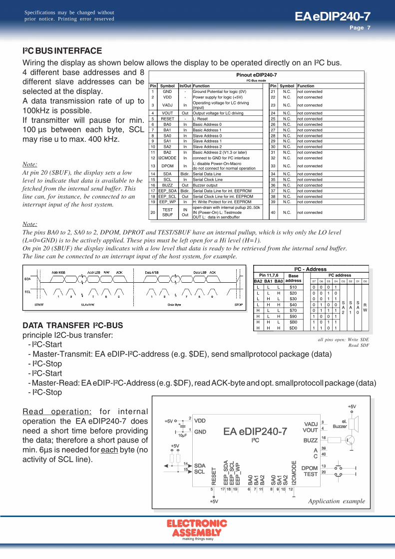
I²C BUS INTERFACEWiring the display as shown below allows the display to be operated directly on an I²C bus.4 different base addresses and 8different slave addresses can beselected at the display.A data transmission rate of up to100kHz is possible.If transmitter will pause for min.100 µs between each byte, SCLmay rise u to max. 400 kHz.
Pinout eDIP240-7I²C-Bus mode
Pin Symbol In/Out Function Pin Symbol Function1 GND - Ground Potential for logic (0V) 21 N.C. not connected2 VDD - Power supply for logic (+5V) 22 N.C. not connected
3 VADJ InOperating voltage for LC driving(input)
23 N.C. not connected
4 VOUT Out Output voltage for LC driving 24 N.C. not connected5 RESET - L: Reset 25 N.C. not connected6 BA0 In Basic Address 0 26 N.C. not connected7 BA1 In Basic Address 1 27 N.C. not connected8 SA0 In Slave Address 0 28 N.C. not connected9 SA1 In Slave Address 1 29 N.C. not connected10 SA2 In Slave Address 2 30 N.C. not connected11 BA2 In Basic Address 2 (V1.3 or later) 31 N.C. not connected12 I2CMODE In connect to GND for I²C interface 32 N.C. not connected
13 DPOM InL: disable Power-On-Macrodo not connect for normal operation
33 N.C. not connected
14 SDA Bidir. Serial Data Line 34 N.C. not connected15 SCL In Serial Clock Line 35 N.C. not connected16 BUZZ Out Buzzer output 36 N.C. not connected17 EEP_SDA Bidir. Serial Data Line for int. EEPROM 37 N.C. not connected18 EEP_SCL Out Serial Clock Line for int. EEPROM 38 N.C. not connected19 EEP_WP In H: Write Protect for int. EEPROM 39 N.C. not connected
20TESTSBUF
INOut
open-drain with internal pullup 20..50kIN (Power-On) L: TestmodeOUT L: data in sendbuffer
40 N.C. not connected
Note:At pin 20 (SBUF), the display sets a lowlevel to indicate that data is available to befetched from the internal send buffer. Thisline can, for instance, be connected to aninterrupt input of the host system.
Application example
I²C - AddressPin 11,7,6 Base
addressI²C address
BA2 BA1 BA0 D7 D6 D5 D4 D3 D2 D1 D0
L L L $10 0 0 0 1
SA2
SA1
SA0
RW
L L H $20 0 0 1 0L H L $30 0 0 1 1
L H H $40 0 1 0 0H L L $70 0 1 1 1
H L H $90 1 0 0 1H H L $B0 1 0 1 1
H H H $D0 1 1 0 1
Note:The pins BA0 to 2, SA0 to 2, DPOM, DPROT and TEST/SBUF have an internal pullup, which is why only the LO level(L=0=GND) is to be actively applied. These pins must be left open for a Hi level (H=1).On pin 20 (SBUF) the display indicates with a low level that data is ready to be retrieved from the internal send buffer.The line can be connected to an interrupt input of the host system, for example.
all pins open: Write $DERead $DF
DATA TRANSFER I²C-BUSprinciple I2C-bus transfer:
- I²C-Start- Master-Transmit: EA eDIP-I²C-address (e.g. $DE), send smallprotocol package (data)- I²C-Stop- I²C-Start- Master-Read: EA eDIP-I²C-Address (e.g. $DF), read ACK-byte and opt. smallprotocoll package (data)- I²C-Stop
Read operation: for internaloperation the EA eDIP240-7 doesneed a short time before providingthe data; therefore a short pause ofmin. 6µs is needed for each byte (noactivity of SCL line).

EA eDIP240-7Page 8
Specifications may be changed withoutprior notice. Printing error reserved
BUILDING THE SMALLPROTOCOL PACKAGES
DATA TRANSFER PROTOCOL (SMALL PROTOCOL)The protocol has an identical structure for all 3 interface types: RS-232, SPI and I²C. Each data transfer isembedded in a fixed frame with a checksum (protocol package). The EA eDIP240-7 acknowledges thispackage with the character <ACK> (=$06) on successful receipt or <NAK> (=$15) in the event of an incorrectchecksum or receive buffer overflow. In the case of <NAK>, the entire package is rejected and must be sentagain.Receiving the <ACK> byte means only that the protocol package is ok, there is no syntaxcheck for the command.Note: it is neccessary to read the <ACK> byte in any case.If the host computer does not receive an acknowledgment, at least one byteis lost. In this case, the set timeout has to elapse before the package is sentagain.The raw data volume per package is limited to 64 bytes (len <= 64).Commands longer than 64 bytes (e.g. Load image ESC UL...) must bedivided up between a number of packages. All data in the packages arecompiled again after being correctly received by the EA eDIP240-7.
DEACTIVATING THE SMALL PROTOCOLFor tests the protocol can be deactivated by closing the solder strap J2 (seepage 20). In normal operation, however, you are urgently advised toactivate the protocol. If you do not, any overflow of the receive buffer will notbe detected.
> <DC1> len data... bcc
< <ACK>
Command/Data to the display
<DC1> = 17(dec.) = $11 <ACK> = 6(dec.) = $06len = count of user data (without <DC1>, without checksum bcc)bcc = 1 byte = sum of all bytes incl. <DC1> and len, modulo 256
The user data is transferred framed by<DC1>, the number of bytes (len) and thechecksum (bcc). The display responds with<ACK>.
> <DC2> 1 S bcc
< <ACK>
< <DC1> len data... bcc
Request for content of send buffer
The command sequence <DC2>, 1, S, bccempties the display’s send buffer. The displayreplies with the acknowledgement <ACK>and the begins to send all the collected datasuch as touch keystrokes.<DC2> = 18(dec.) = $12 1 = 1(dez.) = $01 S = 83(dez.) = $53
<ACK> = 6(dec.) = $06len = count of user data (without <DC2>, without checksum bcc)bcc = 1 byte = sum of all bytes incl. <DC2>, modulo 256
Clear display and draw a line from 0,0 to 239,127
<DC1> len ESC D L ESC G D 0 0 239 127 bcc
$11 $0A $1B $44 $4C $1B $47 $44 $00 $00 $EF $7F $DA →<ACK>
← $06Example to a complete data package
void SendData(unsigned char *buf, unsigned char len){ unsigned char i, bcc;
SendByte(0x11); // Send DC1 bcc = 0x11;
SendByte(len); // Send data length bcc = bcc + len;
for(i=0; i < len; i++) // Send buf { SendByte(buf[i]); bcc = bcc + buf[i]; }
SendByte(bcc); // Send checksum}
„C“ source code to transmit a data package
EA eDIP240-7Page 9
Specifications may be changed withoutprior notice. Printing error reserved
> <DC2> 1 I bcc
< <ACK>
< <DC2> 2 send bufferbytes ready
receive bufferbytes free
bcc
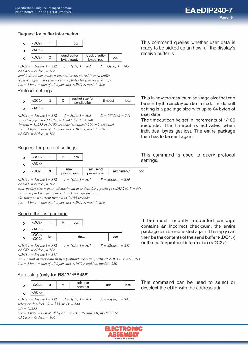
Request for buffer information
<DC2> = 18(dec.) = $12 1 = 1(dez.) = $01 I = 73(dez.) = $49<ACK> = 6(dec.) = $06send buffer bytes ready = count of bytes stored in send bufferreceive buffer bytes free = count of bytes for free receive bufferbcc = 1 byte = sum of all bytes incl. <DC2>, modulo 256
This command queries whether user data isready to be picked up an how full the display'sreceive buffer is.
> <DC2> 3 Dpacket size for
send buffer timeout bcc
< <ACK>
> <DC2> 1 R bcc
< <ACK>
<<DC1><DC2>
len data... bcc
Repeat the last package
Protocol settings
<DC2> = 18(dec.) = $12 3 = 3(dez.) = $03 D = 68(dez.) = $44packet size for send buffer = 1..64 (standard: 64)timeout = 1..255 in 1/100 seconds (standard: 200 = 2 seconds)bcc = 1 byte = sum of all bytes incl. <DC2>, modulo 256<ACK> = 6(dec.) = $06
<DC2> = 18(dec.) = $12 1 = 1(dez.) = $01 R = 82(dez.) = $52<ACK> = 6(dec.) = $06<DC1> = 17(dec.) = $11len = count of user data in byte (without ckecksum, without <DC1> or <DC2>)bcc = 1 byte = sum of all bytes incl. <DC2> and len, modulo 256
If the most recently requested packagecontains an incorrect checksum, the entirepackage can be requested again. The reply canthen be the contents of the send buffer (<DC1>)or the buffer/protocol information (<DC2>).
This is how the maximum package size that canbe sent by the display can be limited. The defaultsetting is a package size with up to 64 bytes ofuser data.The timeout can be set in increments of 1/100seconds. The timeout is activated whenindividual bytes get lost. The entire packagethen has to be sent again.
Request for protocol settings
<DC2> = 18(dec.) = $12 1 = 1(dez.) = $01 P = 80(dez.) = $50<ACK> = 6(dec.) = $06max. packet size = count of maximum user data for 1 package (eDIP240-7 = 64)akt. send packet size = current package size for sendakt. timeout = current timeout in 1/100 secondsbcc = 1 byte = sum of all bytes incl. <DC2>, modulo 256
> <DC2> 1 P bcc
< <ACK>
< <DC2> 3 max.packet size
akt. sendpacket size
akt. timeout bcc
This command is used to query protocolsettings.
Adressing (only for RS232/RS485)
> <DC2> 3 Aselect ordeselect
adr bcc
< <ACK>
<DC2> = 18(dec.) = $12 3 = 3(dez.) = $03 A = 65(dez.) = $41select or deselect: 'S' = $53 or 'D' = $44adr = 0..255bcc = 1 byte = sum of all bytes incl. <DC2> and adr, modulo 256<ACK> = 6(dec.) = $06
This command can be used to select ordeselect the eDIP with the address adr.
EA eDIP240-7Page 10
Specifications may be changed withoutprior notice. Printing error reserved
TOUCH PANEL (EA eDIP240x-7LWTP only)
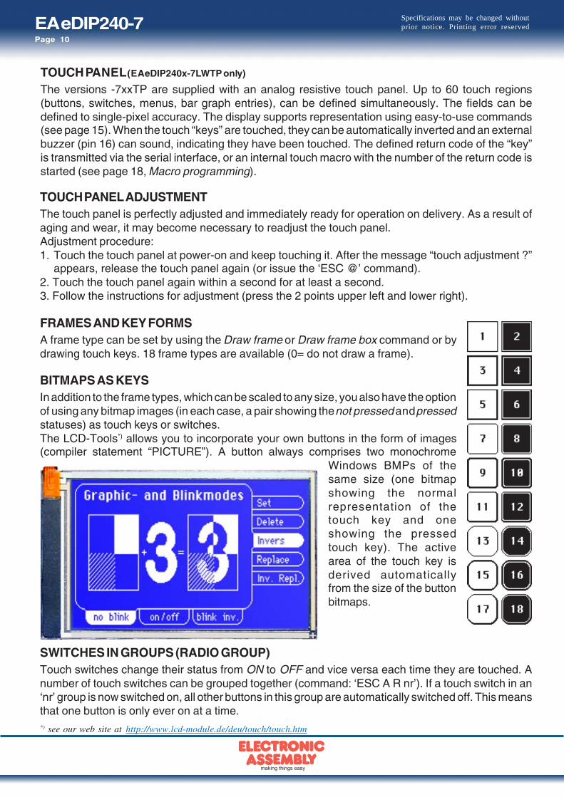
The versions -7xxTP are supplied with an analog resistive touch panel. Up to 60 touch regions(buttons, switches, menus, bar graph entries), can be defined simultaneously. The fields can bedefined to single-pixel accuracy. The display supports representation using easy-to-use commands(see page 15). When the touch “keys” are touched, they can be automatically inverted and an externalbuzzer (pin 16) can sound, indicating they have been touched. The defined return code of the “key”is transmitted via the serial interface, or an internal touch macro with the number of the return code isstarted (see page 18, Macro programming).
TOUCH PANEL ADJUSTMENTThe touch panel is perfectly adjusted and immediately ready for operation on delivery. As a result ofaging and wear, it may become necessary to readjust the touch panel.Adjustment procedure:1. Touch the touch panel at power-on and keep touching it. After the message “touch adjustment ?”
appears, release the touch panel again (or issue the ‘ESC @’ command).2. Touch the touch panel again within a second for at least a second.3. Follow the instructions for adjustment (press the 2 points upper left and lower right).
FRAMES AND KEY FORMSA frame type can be set by using the Draw frame or Draw frame box command or bydrawing touch keys. 18 frame types are available (0= do not draw a frame).
BITMAPS AS KEYSIn addition to the frame types, which can be scaled to any size, you also have the optionof using any bitmap images (in each case, a pair showing the not pressed and pressedstatuses) as touch keys or switches.The LCD-Tools*) allows you to incorporate your own buttons in the form of images(compiler statement “PICTURE”). A button always comprises two monochrome
Windows BMPs of thesame size (one bitmapshowing the normalrepresentation of thetouch key and oneshowing the pressedtouch key). The activearea of the touch key isderived automaticallyfrom the size of the buttonbitmaps.
SWITCHES IN GROUPS (RADIO GROUP)Touch switches change their status from ON to OFF and vice versa each time they are touched. Anumber of touch switches can be grouped together (command: ‘ESC A R nr’). If a touch switch in an‘nr’ group is now switched on, all other buttons in this group are automatically switched off. This meansthat one button is only ever on at a time.*) see our web site at http://www.lcd-module.de/deu/touch/touch.htm
EA eDIP240-7Page 11
Specifications may be changed withoutprior notice. Printing error reserved
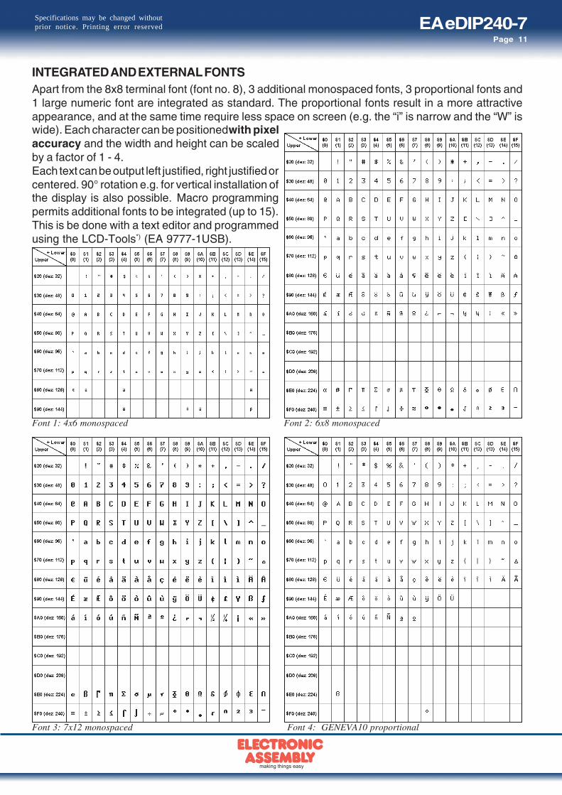
INTEGRATED AND EXTERNAL FONTSApart from the 8x8 terminal font (font no. 8), 3 additional monospaced fonts, 3 proportional fonts and1 large numeric font are integrated as standard. The proportional fonts result in a more attractiveappearance, and at the same time require less space on screen (e.g. the “i” is narrow and the “W” iswide). Each character can be positioned with pixelaccuracy and the width and height can be scaledby a factor of 1 - 4.Each text can be output left justified, right justified orcentered. 90° rotation e.g. for vertical installation ofthe display is also possible. Macro programmingpermits additional fonts to be integrated (up to 15).This is be done with a text editor and programmedusing the LCD-Tools*) (EA 9777-1USB).
Font 4: GENEVA10 proportional
Font 1: 4x6 monospaced Font 2: 6x8 monospaced
Font 3: 7x12 monospaced

EA eDIP240-7Page 12
Specifications may be changed withoutprior notice. Printing error reserved
Font 5: CHICAGO14 proportional
TYPEFACEThis picture of a screen image shows all theintegrated standard fonts.Macro programming permits someadditional fonts to be integrated. Anyconceivable font (including Chinese orCyrillic) can be created with a text editorand programmed using the LCD-Toolkit*)
and programmer EA 9777-1USB.
Font 6: Swiss30 Bold proportional
Font 7: big numbers BigZif57
*) see our web site at http://www.lcd-module.de/deu/touch/touch.htm

EA eDIP240-7Page 13
Specifications may be changed withoutprior notice. Printing error reserved
ALL COMMANDS AT A GLANCEThe built-in intelligence allows an easy creation of your individual screen content. Below mentionedcommands can be used either directly via the serial interface (see page 17) or together with the self-definable macro (see page 18).
EA eDIP240-7: Command table 1 afterresetCommand Codes Remarks
Commands for terminal modeFormfeed FF (dez:12) ^L The contents of the terminal area are deleted and the cursor is placed at pos. (1,1)
Carriage Return CR(13) ^M Cursor to the beginning of the line on the extreme left
Linefeed LF (dez:10) ^J Cursor is set to the next line
Cursor position
ESC T
P n1 n2 n1=column; n2=line; origin upper-left corner (1,1) 1,1Cursor On / Off C n1 n1=0: Cursor is invisible; n1=1: Cursor flashes; 1Terminal invisible A Terminal display not visible; outputs are ignored
Terminal visible E Terminal display is visible again; visiblShow revision code V Show revision code on terminal layer e.g. "EA eDIP240-7 V1.1 Rev.B"
Comands for outputting strings
Output stringL: left justifiedC: centeredR: right justified
ESC Z
Lx1 y1
Text...
NUL
A string (...) is output to xx1,yy1. ´NUL´ ($00), 'LF' ($0A) or 'CR' ($0D) = end of string;several lines are separated by the character '|' ($7C);;text between two '~' ($7E) characters flashes on/off;text between two '@' ($40) characters flashes inversely;
CR
Set font F n1 Set font with the number n1 (0..16) 0Font zoom factor Z n1 n2 n1 = X zoom factor (1x..4x); n2 = Y zoom factor (1x..4x) 1,1Add. line spacing Y n1 Insert n1 pixels between two lines of text as additional line spacing
Text angle W n1 Text output angle: n1=0: 0°; n1=1: 90° 0Text mode V n1 Set mode n1: 1=set; 2=delete; 3=inverse; 4=replace; 5=inverse replace; 4Text blink attribute B n1 n1: 0=text solid, blink off; 1=text blink on/off; 2=text blink inverted; 0String for terminal ESC Z T Text ... Command for outputting a string in a macro to the terminal
Draw straight lines and pointsDraw rectangle
ESC G
R x1 y1 x2 y2 Draw four straight lines as a rectangle from x1,y1 to x2,y2
Draw straight line D x1 y1 x2 y2 Draw straight line from x1,y1 to x2,y2
Continue straight line W x1 y1 Draw a straight line from last end point to x1, y1 0Draw point P x1 y1 Set one dot at coordinates x1, y1
Point size/line thickness Z n1 n2 n1 = X-Punktgröße (1..15); n2 = Y-Punktgröße (1..15); 1,1Graphic mode V n1 Drawing mode n1: 1=set; 2=delete; 3=inverse; 1
Change/draw rectangular areasDelete area
ESC R
L x1 y1 x2 y2 Delete an area from x1,y1 to x2,yy2 (all pixels out)
Invert area I x1 y1 x2 y2 Invert an area from x1,y1 to x2,y2 (invert all pixels
Fill area S x1 y1 x2 y2 Fill an area from x1,y1 to x2,y2 (all pixels on)
Area with fill pattern M x1 y1 x2 y2 n1 Draw an area from x1,y1 to x2,y2 with pattern n1 (always set)
Draw box O x1 y1 x2 y2 n1 Draw a rectangle x1,y1 to x2,y2 with fill pattern n1 (always replace)
Draw frame R x1 y1 x2 y2 n1 Draw a frame of the type n1 from x1,y1 to x2,y2 (always set)
Draw frame box T x1 y1 x2 y2 n1 Draw a frame box of the type n1 from x1,y1 to x2,y2 (always replace)
Bitmap image commandsImage from clipboard
ESC U
C x1 y1 The current contents of the clipboard are loaded to x1,y1 with all the image attributes
Load internal image I x1 y1 no Load internal image with the no. (0..255) from EEPROM to x1,y1
Load image L x1 y1 BLH data ... Load an image to x1,y1; see image structure for image data
Image zoom factor Z n1 n2 n1 = X zoom factor (1x..4x); n2 = Y zoom factor (1x..4x) 1,1Image angle W n1 Output angle: n1=0: 0°; n1=1: 90°; n1=2: 180°; n1=3: 270° 0Image link mode V n1 Mode n1: 1=set; 2=delete; 3=inverse; 4=replace; 5=inverse replace 4
Image flashing attribute B n1n1=0 Image attribute blink off; n1=1 image blink mode on/off; n1=2 image blink modeinverse
0
Send hard copy H x1 y1 x2 y2A full image is requested in Windows BMP format. The image header is sent first viaRS232, followed by the actual image data (9662 bytes).
Display commands (effect on the entire display)Delete display
ESC D
L Delete display contents (all pixels off)
Invert display I Invert display contents (invert all pixels)
Fill display S Fill display contents (all pixels on)
Switch display off A Display contents become invisible but are retained, commands continue to be possible
Switch display on E Display contents become visible again visiblShow clip-board C Show content of clip-board. Standard display output is no longer visible
Show current N Switch back to noraml operation. Standard display output is visible
Flashing area commandsDelete flashing attribute
ESC Q
L x1 y1 x2 y2 Delete the flashing attribute from x1,y1 to x2,y2
Inverted flashing area I x1 y1 x2 y2 Define an inverted flashing area from x1,y1 to x2,y2
Pattern for flashing area M x1 y1 x2 y2 n1 Define flashing area with pattern n1 (on/off) from x1,y1 to x2,y2
Set flashing time Z n1 Set the flashing time n1= 1..15 in 1/10s; 0=deactivate flashing function 6

EA eDIP240-7Page 14
Specifications may be changed withoutprior notice. Printing error reserved
EA eDIP240-7: Command table 2 afterresetCommand Codes Remarks
Bar graph commands
Define bar graph
ESC B
RLOU
n1 x1 y1 x2 y2 sv ev type pat
Define bar graph to L(eft), R(ight), O(ben) (up), U(nten) (down)with the "nr" (1..32). x1,y1,x2,y2 form the rectangle enclosing thebar graph. sv, ev are the values for 0% and 100%.type=0: bar; type=1: bar in rectangle; pat=bar patterntype=2: line; type=3: line in rectangle; pat= line width
Nobar
define
Update bar graph A n1 valu Set and draw the bar graph with the number n1 to the new user "value."
Draw new bar graph Z n1 Draw the bar graph with the number n1 completely
Send bar graph value S n1 Send the current value of bar graph no. n1 on the serial interface
Delete bar graph D n1 n2Makes definition of bar graph with number n1 invalid. If bar graph was defined as a touchfield, active area will become inactive againn2=0: above function and bar graph keeps visible; n2=1: bar graph will be cleared
Clipboard commands (buffer for image areas)Save display contents
ESC C
B The entire contents of the display are copied to the clipboard as an image area
Save area S x1 y1 x2 y2 The image area from x1,y1 to x2,y2 is copied to the clipboard
Restore area R The image area on the clipboard is copied back its original position in the display
Copy area K x1 y1 The image area on the clipboard is copied to x1,y1 in the display
Settings for menu/pop-up and touch panelSet font for menu
ESC N
F n1 All following menu entries will be written in font n1 (0..16) 0Set zoom factor Z n1 n2 n1 = X-zoom factor (1x..4x); n2 = Y-zoom factor (1x..4x) 1,1add. line spacing Y n1 Add n1 dots as additional line spacing between 2 lines
Angle for menu W n1 Pop-up direction: n1=0: 0°; n1=1: 90°; 0
Set automatic function fortouch
T n1n1=1: touch menu will pop-up automatically; n1=0: touch menu will not pop-up but 'ESC T0' will be sent to host; this one is able to pop-up with command 'ESC N T 2' then.
1
Menu/pop-up commands(not valid for touch panel use; for that see table "Commands for the touch panel")
Define menu and show
ESC N
D x1 y1 notext...
NUL
A menu is drawn as of the corner x1,y1 with the current menu font.no= currently inverted entry (e.g.: 1 = 1st. entry) text:= string with menu items.The different items are separated by the character '|' ($7C,dec:124)(e.g. "item1|item2|item3"). The background of the menu is saved automatically. If amenu is already defined, it is automatically canceled+deleted.
Next item N The next item is inverted or remains at the end
Previous item P The previous item is inverted or remains at the beginning
End of menu/send SThe menu is removed from the display and replaced with the original background. Thecurrent item is sent as a number (1..n) (0=no menu displayed)
End of menu/macro M n1The menu is removed from the display and replaced with the original background. Menumacro n1 is called for item 1, menu macro nr+1 for entry 2, and so on
End of menu/cancel A The menu is removed from the display and replaced with the original background
Macro commandsRun macro
ESC M
N n1 Call the (normal) macro with the number n1 (0..255) (max. 7 levels)
Run touch macros T n1 Call the touch macro with the number n1 (0..255) (max. 7 levels)
Run menu macro M n1 Call the menu macro with the number n1 (0..255) (max. 7 levels)
Automatic/cyclic macro
Macro with delay
ESC M
G n1 ts(normal-) macro n1 (0..255) runs after delay of ts/10s.May be stopped/prevented by any command via serial interface or by touch panel
Autom. macro cyclical,once
E n1 n2 tsAutomatically macros n1..n2 once only; ts=pause in 1/10s.Will be stopped by any command via serial interface or by touch panel use
Autom. macro cyclical A n1 n2 tsAutomatically macros n1..n2 cyclically; ts=pause in 1/10s.Will be stopped by any command via serial interface or by touch panel use
Autom. macro pingpong J n1 n2 tsAutomatically macros n1..n2..n1 (pingpong); ts=pause in 1/10s.Will be stopped by any command via serial interface or by touch panel use
Process macro commands (from V1.1)
Define process macro
ESC M
D no type n3 n4 tsDefine process macro number no (1..4) (1=highest priority).(normal-) macro n3..n4 will be served with ts/10s delay.type: 1=once only; 2=cyclical; 3=pingpong n3..n4..n3
Process macro speed Z no ts Assign a new delay for process no (1..4) with ts /10s value. ts=0 will stop the automatic
Stop process macro S n1All process macro will be stopped with n1=0 and continued with n1=1e.g. to make settings or output via serial interface without interference
1
Other commandsWait (pause) ESC X ts Wait ts tenths of a second before the next command is executed.
Beep on/off
ESC Y
S tsSwitch beeper output (pin 16) ts=2..255 for ts 1/10s to hights=0 set permanent low, ts=1 set permanent high
OFF
Backlight on/off L tsLED backlight n1=0: OFF; n1=1: ON;ts=2..255: switches backlight on for ts /10s and then off
1
Backlight brightness H n1 Adjust brightness of backlight n1=0..100% (non linear) 100
Send bytesESC S
B cnt data ...cnt (=1..255) bytes are sent via serial interfacedata ... = cnt. bytes (e.g. control of an external printer)
Send version V Software versionwill be sent as a string ;e.g. "EA eDIP240-7 V1.2 Rev.B"
EA eDIP240-7Page 15
Specifications may be changed withoutprior notice. Printing error reserved
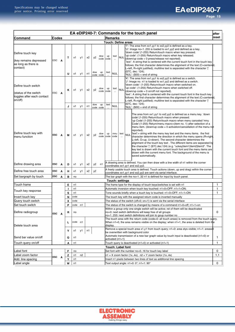
EA eDIP240-7: Commands for the touch panel afterresetCommand Codes Remarks
Touch: Define areas
Define touch key
(key remains depressedas long as there iscontact)
ESC AT x1 y1 x2 y2
dowcode
upcode
text... NUL
'T': The area from xx1,yy1 to xx2,yy2 is defined as a key.'U': Image no=1..255 is loaded to xx1,yy2 and defined as a key.'down code':(1-255) Return/touch macro when key pressed.'up code': (1-255) Return/touch macro when key released.(down/up code = 0 press/release not reported).´text´: A string that is centered with the current touch font in the touch keyfollows; the first character determines the alignment of the text (C=centered,L=left, R=right justified); multiline text is separated with the character '|'($7C, dec: 124);'NUL': ($00) = end of stringU x1 y1 n1
dowcode
upcode
text... NUL
Define touch switch
(status of the switchtoggles after each contacton/off)
ESC AK x1 y1 x2 y2
dowcode
upcode
text... NUL
'K': The area from xx1,yy1 to xx2,yy2 is defined as a switch.'J': Image no. n1 is loaded to xx1,yy2 and defined as a switch.'down code': (1-255) Return/touch macro when switched on.'up code': (1-255) Return/touch macro when switched off.(down/up code = 0 on/off not reported).'text´: A string that is centered with the current touch font in the touch keyfollows; the first character determines the alignment of the text (C=centered,L=left, R=right justified); multiline text is separated with the character '|'($7C, dec: 124);'NUL': ($00) = end of stringJ x1 y1 n1
dowcode
upcode
text... NUL
Define touch key withmenu function
ESC A M x1 y1 x2 y2dowcode
upcode
mnucode
text... NUL
The area from xx1,yy1 to xx2,yy2 is defined as a menu key. 'downcode':(1-255) Return/touch macro when pressed.'up Code':(1-255) Return/touch macro when menu canceled 'mnuCode':(1-255) Return/menu macro+(item no. 1) after selection of amenu item. (down/up code = 0 activation/cancellation of the menu notreported).'text':= string with the menu key text and the menu items. the firstcharacter determines the direction in which the menu opens (R=right,L=left, O=up, U=down). The second character determines thealignment of the touch key text . The different items are separated bythe character '|' ($7C,dec:124) (e.g. "uckey|item1|item2|item3". Thekey text is drawn with the current touch font and the menu items aredrawn with the current menu font. The background of the menu issaved automatically.
Define drawing area ESC A D x1 y1 x2 y2 n1A drawing area is defined. You can then draw with a line width of n1 within the cornercoordinates xx1,yy1 and xx2,yy2.
Define free touch area ESC A H x1 y1 x2 y2A freely usable touch area is defined. Touch actions (down, up and drag) within the cornercoordinates xx1,yy1 and xx2,yy2 are sent via serial interface.
Set bargraph by touch ESC A B no The bar graph with the no=1..32 n1 is defined for input by touch panel.
Touch: settingsTouch frame
ESC A
E n1 The frame type for the display of touch keys/switches is set with n1 1
Touch key responseI n1 Automatic inversion when touch key touched: n1=0=OFF; n1=1=ON; 1S n1 Tone sounds briefly when a touch key is touched: n1=0=OFF; n1=1=ON 1
Invert touch key N code The touch key with the assigned return code is inverted manually
Query touch switch X code The status of the switch (off=0; on=1) is sent via the serial interface
Set touch switch P code n1 The status of the switch is changed by means of a command n1=0=off; n1=1=on
Define radiogroup R noWithin a group only one single switch will be active; ret of them will be deactivatedno=0: next switch definitions will keep free of all groupsno=1..255: next switch definitions will join to goup number no
0
Delete touch areaL code n1
The touch area with the return code (code=0: all touch areas) is removed from the touch query.When n1=0, the area remains visible on the display; when n1=1, the area is deleted from thedisplay.
V x1 y1 n1Remove a special touch area x1,y1 from touch query; n1=0: area stys visible; n1=1: areawillbe overwritten with background color
Send bar value on/off Q n1Automatic transmission of a new bar graph value by touch input is deactivated (n1=0) oractivated (n1=1)
1
Touch query on/off A n1 Touch query is deactivated (n1=0) or activated (n1=1) 1
Touch: Label fontLabel font
ESC A
F no Set font with the number no=0..16 for touch key label 0Label zoom factor Z n1 n2 n1 = X zoom factor (1x..4x); n2 = Y zoom factor (1x..4x) 1,1Add. line spacing Y n1 Insert n1 pixels between two lines of text as additional line spacing
Label angle W n1 Text output angle: n1=0: 0°; n1=1: 90° 0
EA eDIP240-7Page 16
Specifications may be changed withoutprior notice. Printing error reserved
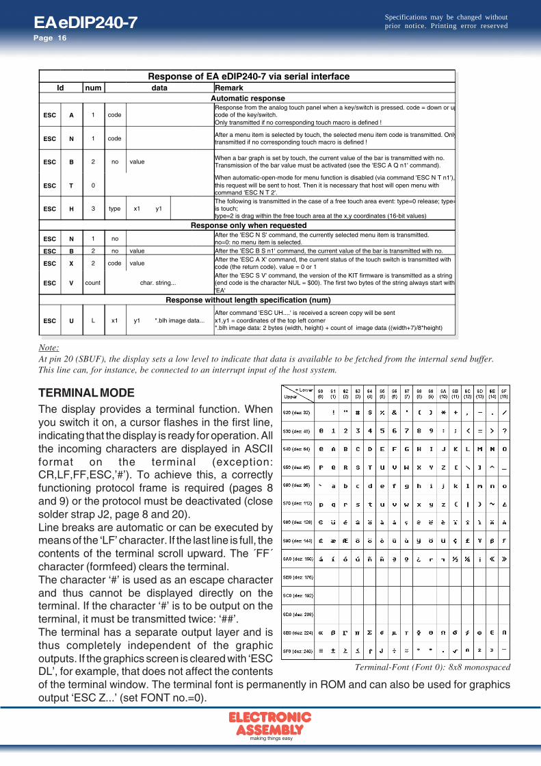
TERMINAL MODEThe display provides a terminal function. Whenyou switch it on, a cursor flashes in the first line,indicating that the display is ready for operation. Allthe incoming characters are displayed in ASCIIformat on the terminal (exception:CR,LF,FF,ESC,’#’). To achieve this, a correctlyfunctioning protocol frame is required (pages 8and 9) or the protocol must be deactivated (closesolder strap J2, page 8 and 20).Line breaks are automatic or can be executed bymeans of the ‘LF’ character. If the last line is full, thecontents of the terminal scroll upward. The ´FF´character (formfeed) clears the terminal.The character ‘#’ is used as an escape characterand thus cannot be displayed directly on theterminal. If the character ‘#’ is to be output on theterminal, it must be transmitted twice: ‘##’.The terminal has a separate output layer and isthus completely independent of the graphicoutputs. If the graphics screen is cleared with ‘ESCDL’, for example, that does not affect the contentsof the terminal window. The terminal font is permanently in ROM and can also be used for graphicsoutput ‘ESC Z...’ (set FONT no.=0).
Response of EA eDIP240-7 via serial interfaceId num data Remark
Automatic response
ESC A 1 codeResponse from the analog touch panel when a key/switch is pressed. code = down or upcode of the key/switch.Only transmitted if no corresponding touch macro is defined !
ESC N 1 codeAfter a menu item is selected by touch, the selected menu item code is transmitted. Onlytransmitted if no corresponding touch macro is defined !
ESC B 2 no valueWhen a bar graph is set by touch, the current value of the bar is transmitted with no.Transmission of the bar value must be activated (see the 'ESC A Q n1' command).
ESC T 0When automatic-open-mode for menu function is disabled (via command 'ESC N T n1'),this request will be sent to host. Then it is necessary that host will open menu withcommand 'ESC N T 2'.
ESC H 3 type x1 y1The following is transmitted in the case of a free touch area event: type=0 release; type=is touch;type=2 is drag within the free touch area at the x,y coordinates (16-bit values)
Response only when requested
ESC N 1 noAfter the 'ESC N S' command, the currently selected menu item is transmitted.no=0: no menu item is selected.
ESC B 2 no value After the 'ESC B S n1' command, the current value of the bar is transmitted with no.
ESC X 2 code valueAfter the 'ESC A X' command, the current status of the touch switch is transmitted withcode (the return code). value = 0 or 1
ESC V count char. string...After the 'ESC S V' command, the version of the KIT firmware is transmitted as a string(end code is the character NUL = $00). The first two bytes of the string always start with'EA'
Response without length specification (num)
ESC U L x1 y1 *.blh image data...After command 'ESC UH....' is received a screen copy will be sentx1,y1 = coordinates of the top left corner*.blh image data: 2 bytes (width, height) + count of image data ((width+7)/8*height)
Note:At pin 20 (SBUF), the display sets a low level to indicate that data is available to be fetched from the internal send buffer.This line can, for instance, be connected to an interrupt input of the host system.
Terminal-Font (Font 0): 8x8 monospaced

EA eDIP240-7Page 17
Specifications may be changed withoutprior notice. Printing error reserved
FILL PATTERNSA pattern type can be set as a parameter with some commands. In this way, rectangular areas and bargraphs for instance can be filled with different patterns. There are 16 internal fill patterns available.
USING THE SERIAL INTERFACEThe EA eDIP240-7 can be programmed by means of various integrated commands. Each commandbegins with ESCAPE or HASH followed by one or two command letters and some parameters.There thus are two ways to send commands:
1. ASCII mode- The ESC character corresponds to the character ‘#’ (hex: $23, dec: 35).- The command letters come directly after the ‘#’ character.- The parameters are transmitted as plain text (several ASCII characters) followed by a separating
character (such as a comma ‘,’) - also after the last parameter e.g.: #GD0,0,239,127,- Strings (text) are written directly without quotation marks and terminated with CR (hex: $0D) or LF
(hex: $0A).
2. Binary mode- The escape character corresponds to the character ESC (hex: $1B, dec: 27).- The command letters are sent directly.- The x, y coordinates and all the other parameters are transmitted as 8-bit binary values (1 byte).- Strings (text) are terminated with CR (hex: $0D) or LF (hex: $0A) or NUL (hex: $00).
No separating characters, such as spaces or commas, may be used in binary mode. The commandsrequire no final byte, such as a carriage return (apart from the string: $00).

EA eDIP240-7Page 18
Specifications may be changed withoutprior notice. Printing error reserved
MACRO PROGRAMMINGSingle or multiple command sequences can be grouped together in macros and stored in theEEPROM. You can then start them by using the Run macro commands. There are different types ofmacro:Normal macros (0 through 255)These are started by means of an ‘ESC MN xx’ command via the serial interface or from another macro.A series of macros occurring one after the other can be called cyclically (movie, hourglass, multi-pagehelp text). These automatic macros continue to be processed until a command is received via RS-232or another macro is activated.Furthermore these macros may be started by "macro processes" as an individual task (from V1.1).Process macros will not be interupted by any other commands or touch panel use.Touch macro (1 through 255)Started when you touch/release a touch field (only in versions with a touch panel - TP) or issue an‘ESC MT xx’ command.Menu macro (1 through 255)Started when you choose a menu item or issue an ‘ESC MM xx’ command.Power-on macroStarted after power-on. You can switch off the cursor and define an opening screen, for example.Reset macroStarted after an external reset or after a voltage dip under 4.7V (VDD-VSS).Watchdog macroStarted after a fault/error (e.g. crash).Brown-out macroStarted after a voltage dip <4V.Important: If a continuous loop is programmed in the power-on, reset or watchdog macro, the displaycan no longer be addressed. In this event, execution of the power-on macro must be suppressed. Thisis achieved by wiring DPOM appropriately.PowerOff - connect pin 13 (DPOM) to GND - PowerOn - disconnect pin 13 again.
WRITE PROTECTION FOR MACRO PROGRAMMING AND FONTSA VDD line level at pin 19 (EEP_WP) prevents inadvertent overwriting of the macros, images and fontsin the EEPROM (recommanded in any case!).
MEMORY EXPANSIONThe size of the internal EEPROM memory is 32 kB. Generally, this allows sufficient space for a largenumber of images and macros. If, however, a very large number of images (in particular full-sizeimages) are to be stored, it can be necessary to expand the memory. The memory capacity can bedoubled by directly connecting a standard EEPROM of the 24C256 series. It is connected over pins17, 18 and 19 (I2C adress $A6) or can be placed direct as U12 (see drawing on page 20).
EA eDIP240-7Page 19
Specifications may be changed withoutprior notice. Printing error reserved
IMAGES STORED IN EEPROMTo reduce the transmission times at the interface or to save storage space in the processor system,up to 256 images can be stored in the internal EEPROM. They can be called using the “ESC U I”command or from within a macro. Any images in Windows BMP format (monochrome images only)can be used. They can be created and edited using commercial software such as Windows Paint orPhotoshop (only black and white = 1 bit).
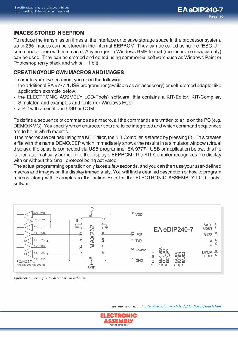
CREATING YOUR OWN MACROS AND IMAGESTo create your own macros, you need the following:- the additional EA 9777-1USB programmer (available as an accessory) or self-created adaptor like
application example below,- the ELECTRONIC ASSMBLY LCD-Tools*) software; this contains a KIT-Editor, KIT-Compiler,
Simulator, and examples and fonts (for Windows PCs)- a PC with a serial port USB or COM
To define a sequence of commands as a macro, all the commands are written to a file on the PC (e.g.DEMO.KMC). You specify which character sets are to be integrated and which command sequencesare to be in which macros.If the macros are defined using the KIT Editor, the KIT Compiler is started by pressing F5. This createsa file with the name DEMO.EEP which immediately shows the results in a simulator window (virtualdisplay). If display is connected via USB programmer EA 9777-1USB or application below, this fileis then automatically burned into the display’s EEPROM. The KIT Compiler recognizes the displaywith or without the small protocol being activated.The actual programming operation only takes a few seconds, and you can then use your user-definedmacros and images on the display immediately. You will find a detailed description of how to programmacros along with examples in the online Help for the ELECTRONIC ASSEMBLY LCD-Tools*)
software.
*) see our web site at http://www.lcd-module.de/deu/touch/touch.htm
Application example to direct pc interfacing

EA eDIP240-7Page 20
Specifications may be changed withoutprior notice. Printing error reserved
Zeppelinstraße 19 · D-82205 Gilching · Phone +49-(0)8105-778090 · Fax +49-(0)8105-778099 · www.lcd-module.de · [email protected]
DIMENSIONS
all dimensions are in mm
ATTENTION
handling precautions!
Notes on handling and operation- LC dispalys are designed for hand soldering only.
Reflow and wave soldering may destroy lcdimmediately
- The following can lead to the electronicdestruction of the module: cross-polarity orovervoltage of the power supply, overvoltage orcross-polarity or static discharge at the inputs,short-circuits at the outputs.
- The power supply must be disconnected before themodule is removed. All inputs must also be free ofvoltage.
- The display and the touch screen are made ofplastic and must not come into contact with hardobjects. The surfaces can be cleaned with a softcloth. No solvents may be used.
- The module is designed only for operation withinbuildings. Additional measures must be taken toallow operation in the open air. The maximumtemperature range of -20 through +70°C must notbe exceeded. The module may not operatecorrectly and may fail if used in a humidenvironment. The display must be shielded fromdirect sunlight.
J2: switch off Small ProtocollJ6: Connect Metal frame with GND(ESD / EMV)
EA 0FP241-7SW:dimensions in mm
ALUMINIUM BEZEL


![Index [application.wiley-vch.de]digital memory 114 digital mirror device 215 digital MOS circuit 53 digital power management 485 digital products 568 digital signal 55 digital technology](https://img.dokumen.tips/doc/110x75/5f08ef357e708231d4246eeb/index-digital-memory-114-digital-mirror-device-215-digital-mos-circuit-53-digital.jpg)