Embed Size (px)
Citation preview
Data Sheet T 9555 EN
Associated Information Sheet u T 9500 Edition May 2014
1
12
10987
6
5
43
2
Media 5 Media 6 Media 05
Media 4
11
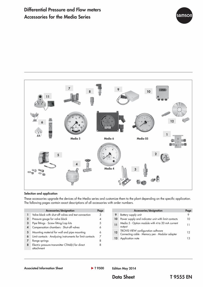
Differential Pressure and Flow metersAccessories for the Media Series
Selection and applicationThese accessories upgrade the devices of the Media series and customize them to the plant depending on the specific application. The following pages contain exact descriptions of all accessories with order numbers.
Accessories/designation Page1 Valve block with shut-off valves and test connection 32 Pressure gauge for valve block 43 Pipe fittings · Screw fitting/cap kits 54 Compensation chambers · Shut-off valves 6
5 Mounting material for wall and pipe mounting 66 Limit contacts · Analyzing instruments for limit contacts 77 Range springs 88 Electric pressure transmitter CTMd(r) for direct
attachment8
Accessories/designation Page9 Battery supply unit 9
10 Power supply and indicator unit with limit contacts 10
11 Media 5 · Option module with 4 to 20 mA current output 11
12 TROVIS-VIEW configuration software Connecting cable · Memory pen · Modular adapter 12
13 Application note 13
2 T 9555 EN
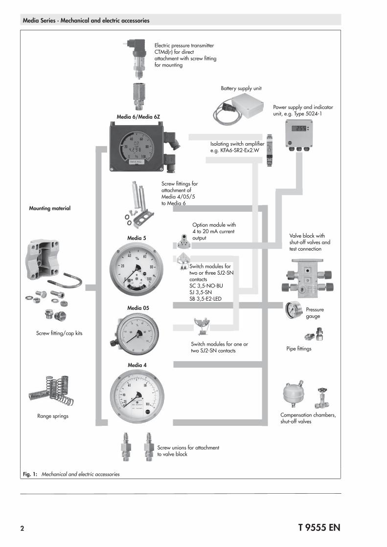
Media Series ∙ Mechanical and electric accessories
Media 5
Media 05
Media 4
Media 6/Media 6Z
Mounting material
Screw unions for attachment to valve block
Screw fitting/cap kits
Switch modules for one or two SJ2-SN contacts
Range springs
Power supply and indicator unit, e.g. Type 5024-1
Battery supply unit
Isolating switch amplifier e.g. KFA6-SR2-Ex2.W
Electric pressure transmitter CTMd(r) for direct attachment with screw fitting for mounting
Screw fittings for attachment of Media 4/05/5 to Media 6
Valve block with shut-off valves and test connection
Compensation chambers, shut-off valves
Pipe fittings
Pressure gauge
Option module with 4 to 20 mA current output
Switch modules for two or three SJ2-SN contacts SC 3,5-NO-BU SJ 3,5-SN SB 3,5-E2-LED
Fig. 1: Mechanical and electric accessories
T 9555 EN 3
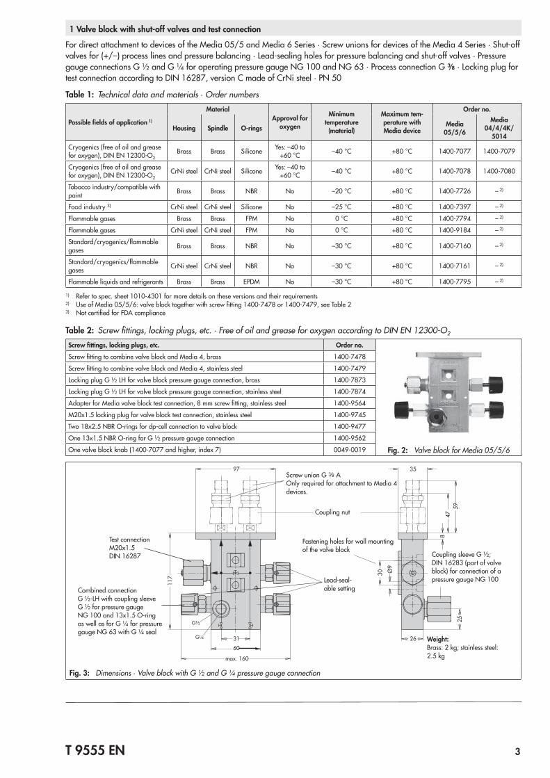
1 Valve block with shut-off valves and test connection
For direct attachment to devices of the Media 05/5 and Media 6 Series · Screw unions for devices of the Media 4 Series · Shut-off valves for (+/–) process lines and pressure balancing · Lead-sealing holes for pressure balancing and shut-off valves · Pressure gauge connections G ½ and G ¼ for operating pressure gauge NG 100 and NG 63 · Process connection G 3/8 · Locking plug for test connection according to DIN 16287, version C made of CrNi steel · PN 50
Table 1: Technical data and materials ∙ Order numbers
Possible fields of application 1)
MaterialApproval for
oxygen
Minimum temperature (material)
Maximum tem-perature with Media device
Order no.
Housing Spindle O-rings Media 05/5/6
Media 04/4/4K/
5014Cryogenics (free of oil and grease for oxygen), DIN EN 12300-O2
Brass Brass Silicone Yes: –40 to +60 °C –40 °C +80 °C 1400-7077 1400-7079
Cryogenics (free of oil and grease for oxygen), DIN EN 12300-O2
CrNi steel CrNi steel Silicone Yes: –40 to +60 °C –40 °C +80 °C 1400-7078 1400-7080
Tobacco industry/compatible with paint Brass Brass NBR No –20 °C +80 °C 1400-7726 – 2)
Food industry 3) CrNi steel CrNi steel Silicone No –25 °C +80 °C 1400-7397 – 2)
Flammable gases Brass Brass FPM No 0 °C +80 °C 1400-7794 – 2)
Flammable gases CrNi steel CrNi steel FPM No 0 °C +80 °C 1400-9184 – 2)
Standard/cryogenics/flammable gases Brass Brass NBR No –30 °C +80 °C 1400-7160 – 2)
Standard/cryogenics/flammable gases CrNi steel CrNi steel NBR No –30 °C +80 °C 1400-7161 – 2)
Flammable liquids and refrigerants Brass Brass EPDM No –30 °C +80 °C 1400-7795 – 2)
1) Refer to spec. sheet 1010-4301 for more details on these versions and their requirements2) Use of Media 05/5/6: valve block together with screw fitting 1400-7478 or 1400-7479, see Table 23) Not certified for FDA compliance
Table 2: Screw fittings, locking plugs, etc. · Free of oil and grease for oxygen according to DIN EN 12300-O2
Screw fittings, locking plugs, etc. Order no.Screw fitting to combine valve block and Media 4, brass 1400-7478
Screw fitting to combine valve block and Media 4, stainless steel 1400-7479
Locking plug G ½ LH for valve block pressure gauge connection, brass 1400-7873
Locking plug G ½ LH for valve block pressure gauge connection, stainless steel 1400-7874
Adapter for Media valve block test connection, 8 mm screw fitting, stainless steel 1400-9564
M20x1.5 locking plug for valve block test connection, stainless steel 1400-9745
Two 18x2.5 NBR O-rings for dp-cell connection to valve block 1400-9477
One 13x1.5 NBR O-ring for G ½ pressure gauge connection 1400-9562
One valve block knob (1400-7077 and higher, index 7) 0049-0019 Fig. 2: Valve block for Media 05/5/6
117 30 Ø
9
847
59
31 26
60
97 35
max. 160
25G½
G¼
Screw union G 3/8 A Only required for attachment to Media 4 devices.
Combined connection G ½-LH with coupling sleeve G ½ for pressure gauge NG 100 and 13x1.5 O-ring as well as for G ¼ for pressure gauge NG 63 with G ¼ seal
Coupling nut
Fastening holes for wall mounting of the valve block
Lead-seal-able setting
Coupling sleeve G ½; DIN 16283 (part of valve block) for connection of a pressure gauge NG 100
Test connection M20x1.5 DIN 16287
Weight:Brass: 2 kg; stainless steel: 2.5 kg
Fig. 3: Dimensions ∙ Valve block with G ½ and G ¼ pressure gauge connection
4 T 9555 EN
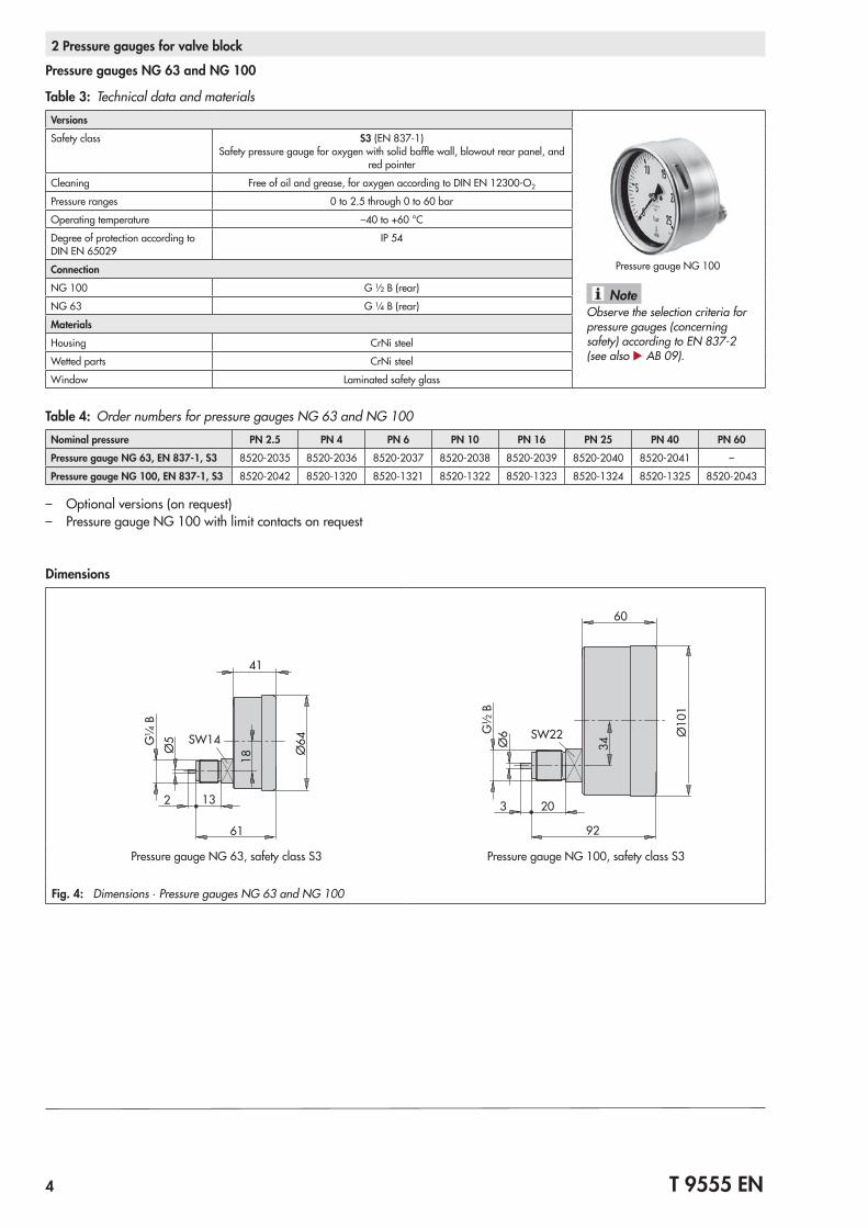
2 Pressure gauges for valve block
Pressure gauges NG 63 and NG 100
Table 3: Technical data and materialsVersions
Pressure gauge NG 100
Observe the selection criteria for pressure gauges (concerning safety) according to EN 837-2 (see also u AB 09).
Note
Safety class S3 (EN 837-1) Safety pressure gauge for oxygen with solid baffle wall, blowout rear panel, and
red pointer
Cleaning Free of oil and grease, for oxygen according to DIN EN 12300-O2
Pressure ranges 0 to 2.5 through 0 to 60 bar
Operating temperature –40 to +60 °C
Degree of protection according to DIN EN 65029
IP 54
ConnectionNG 100 G ½ B (rear)
NG 63 G ¼ B (rear)
MaterialsHousing CrNi steel
Wetted parts CrNi steel
Window Laminated safety glass
Table 4: Order numbers for pressure gauges NG 63 and NG 100Nominal pressure PN 2.5 PN 4 PN 6 PN 10 PN 16 PN 25 PN 40 PN 60Pressure gauge NG 63, EN 837-1, S3 8520-2035 8520-2036 8520-2037 8520-2038 8520-2039 8520-2040 8520-2041 –
Pressure gauge NG 100, EN 837-1, S3 8520-2042 8520-1320 8520-1321 8520-1322 8520-1323 8520-1324 8520-1325 8520-2043
– Optional versions (on request) – Pressure gauge NG 100 with limit contacts on request
Dimensions
61
41
SW14
18
2 13
G¼
BØ
5
Ø64
G½
B
92
60
SW22
34
3 20
Ø6 Ø
101
Pressure gauge NG 63, safety class S3 Pressure gauge NG 100, safety class S3
Fig. 4: Dimensions ∙ Pressure gauges NG 63 and NG 100
T 9555 EN 5
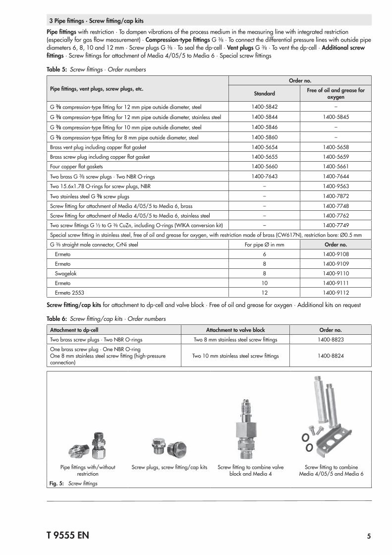
3 Pipe fittings · Screw fitting/cap kits
Pipe fittings with restriction · To dampen vibrations of the process medium in the measuring line with integrated restriction (especially for gas flow measurement) · Compression-type fittings G 3/8 · To connect the differential pressure lines with outside pipe diameters 6, 8, 10 and 12 mm · Screw plugs G 3/8 · To seal the dp-cell · Vent plugs G 3/8 · To vent the dp-cell · Additional screw fittings · Screw fittings for attachment of Media 4/05/5 to Media 6 · Special screw fittings
Table 5: Screw fittings ∙ Order numbers
Pipe fittings, vent plugs, screw plugs, etc.Order no.
Standard Free of oil and grease for oxygen
G 3/8 compression-type fitting for 12 mm pipe outside diameter, steel 1400-5842 –
G 3/8 compression-type fitting for 12 mm pipe outside diameter, stainless steel 1400-5844 1400-5845
G 3/8 compression-type fitting for 10 mm pipe outside diameter, steel 1400-5846 –
G 3/8 compression-type fitting for 8 mm pipe outside diameter, steel 1400-5860 –
Brass vent plug including copper flat gasket 1400-5654 1400-5658
Brass screw plug including copper flat gasket 1400-5655 1400-5659
Four copper flat gaskets 1400-5660 1400-5661
Two brass G 3/8 screw plugs · Two NBR O-rings 1400-7643 1400-7644
Two 15.6x1.78 O-rings for screw plugs, NBR – 1400-9563
Two stainless steel G 3/8 screw plugs – 1400-7872
Screw fitting for attachment of Media 4/05/5 to Media 6, brass – 1400-7748
Screw fitting for attachment of Media 4/05/5 to Media 6, stainless steel – 1400-7762
Two screw fittings G ½ to G 3/8 CuZn, including O-rings (WIKA conversion kit) – 1400-7749
Special screw fitting in stainless steel, free of oil and grease for oxygen, with restriction made of brass (CW617N), restriction bore: Ø0.5 mm
G 3/8 straight male connector, CrNi steel For pipe Ø in mm Order no.
Ermeto 6 1400-9108
Ermeto 8 1400-9109
Swagelok 8 1400-9110
Ermeto 10 1400-9111
Ermeto 2553 12 1400-9112
Screw fitting/cap kits for attachment to dp-cell and valve block · Free of oil and grease for oxygen · Additional kits on request
Table 6: Screw fitting/cap kits · Order numbers
Attachment to dp-cell Attachment to valve block Order no.
Two brass screw plugs · Two NBR O-rings Two 8 mm stainless steel screw fittings 1400-8823
One brass screw plug · One NBR O-ring One 8 mm stainless steel screw fitting (high-pressure connection)
Two 10 mm stainless steel screw fittings 1400-8824
Pipe fittings with/without restriction
Screw plugs, screw fitting/cap kits Screw fitting to combine valve block and Media 4
Screw fitting to combine Media 4/05/5 and Media 6
Fig. 5: Screw fittings
6 T 9555 EN
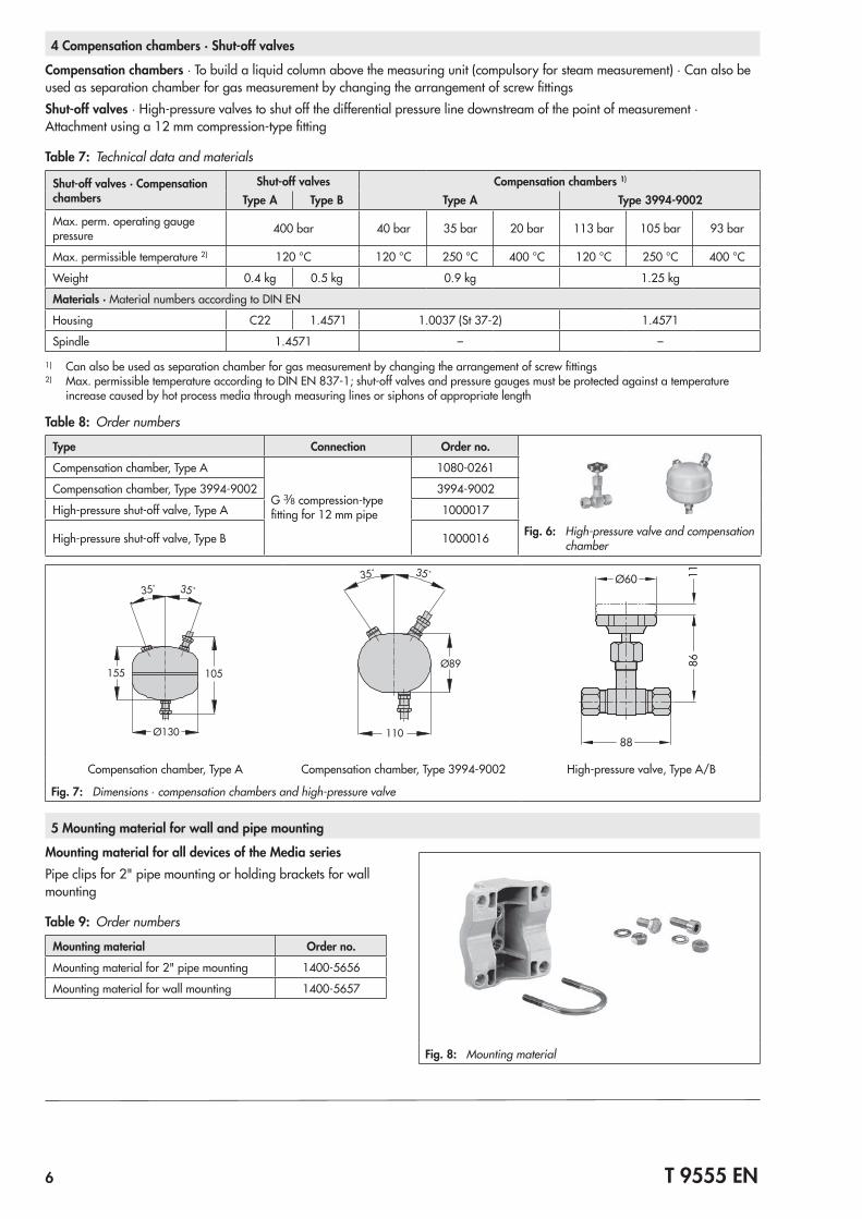
4 Compensation chambers · Shut-off valves
Compensation chambers · To build a liquid column above the measuring unit (compulsory for steam measurement) · Can also be used as separation chamber for gas measurement by changing the arrangement of screw fittingsShut-off valves · High-pressure valves to shut off the differential pressure line downstream of the point of measurement · Attachment using a 12 mm compression-type fitting
Table 7: Technical data and materials
Shut-off valves · Compensation chambers
Shut-off valves Compensation chambers 1)
Type A Type B Type A Type 3994-9002
Max. perm. operating gauge pressure 400 bar 40 bar 35 bar 20 bar 113 bar 105 bar 93 bar
Max. permissible temperature 2) 120 °C 120 °C 250 °C 400 °C 120 °C 250 °C 400 °C
Weight 0.4 kg 0.5 kg 0.9 kg 1.25 kg
Materials · Material numbers according to DIN EN
Housing C22 1.4571 1.0037 (St 37-2) 1.4571
Spindle 1.4571 – –
1) Can also be used as separation chamber for gas measurement by changing the arrangement of screw fittings2) Max. permissible temperature according to DIN EN 837-1; shut-off valves and pressure gauges must be protected against a temperature
increase caused by hot process media through measuring lines or siphons of appropriate length
Table 8: Order numbers
Type Connection Order no.
Compensation chamber, Type A
G 3/8 compression-type fitting for 12 mm pipe
1080-0261
Compensation chamber, Type 3994-9002 3994-9002
High-pressure shut-off valve, Type A 1000017
High-pressure shut-off valve, Type B 1000016 Fig. 6: High-pressure valve and compensation chamber
35˚35˚
155 105
Ø130
35˚35˚
Ø89
110
Ø60
88
1186
Compensation chamber, Type A Compensation chamber, Type 3994-9002 High-pressure valve, Type A/B
Fig. 7: Dimensions ∙ compensation chambers and high-pressure valve
5 Mounting material for wall and pipe mounting
Mounting material for all devices of the Media seriesPipe clips for 2" pipe mounting or holding brackets for wall mounting
Table 9: Order numbers
Mounting material Order no.
Mounting material for 2" pipe mounting 1400-5656
Mounting material for wall mounting 1400-5657
Fig. 8: Mounting material
T 9555 EN 7
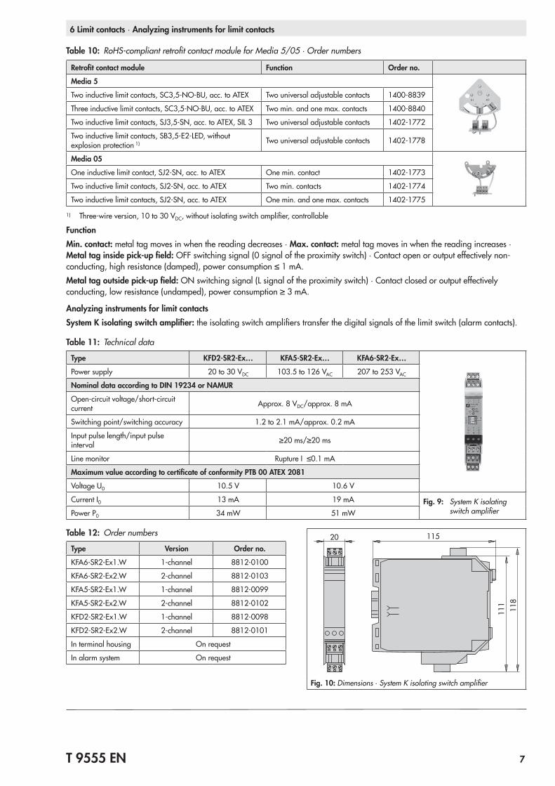
6 Limit contacts ∙ Analyzing instruments for limit contacts
Table 10: RoHS-compliant retrofit contact module for Media 5/05 · Order numbers
Retrofit contact module Function Order no.
Media 5
Two inductive limit contacts, SC3,5-NO-BU, acc. to ATEX Two universal adjustable contacts 1400-8839
Three inductive limit contacts, SC3,5-NO-BU, acc. to ATEX Two min. and one max. contacts 1400-8840
Two inductive limit contacts, SJ3,5-SN, acc. to ATEX, SIL 3 Two universal adjustable contacts 1402-1772
Two inductive limit contacts, SB3,5-E2-LED, without explosion protection 1) Two universal adjustable contacts 1402-1778
Media 05
One inductive limit contact, SJ2-SN, acc. to ATEX One min. contact 1402-1773
Two inductive limit contacts, SJ2-SN, acc. to ATEX Two min. contacts 1402-1774
Two inductive limit contacts, SJ2-SN, acc. to ATEX One min. and one max. contacts 1402-1775
1) Three-wire version, 10 to 30 VDC, without isolating switch amplifier, controllable
FunctionMin. contact: metal tag moves in when the reading decreases · Max. contact: metal tag moves in when the reading increases · Metal tag inside pick-up field: OFF switching signal (0 signal of the proximity switch) · Contact open or output effectively non-conducting, high resistance (damped), power consumption ≤ 1 mA.Metal tag outside pick-up field: ON switching signal (L signal of the proximity switch) · Contact closed or output effectively conducting, low resistance (undamped), power consumption ≥ 3 mA.
Analyzing instruments for limit contactsSystem K isolating switch amplifier: the isolating switch amplifiers transfer the digital signals of the limit switch (alarm contacts).
Table 11: Technical data
Type KFD2-SR2-Ex… KFA5-SR2-Ex… KFA6-SR2-Ex…
Power supply 20 to 30 VDC 103.5 to 126 VAC 207 to 253 VAC
Nominal data according to DIN 19234 or NAMUR
Open-circuit voltage/short-circuit current Approx. 8 VDC/approx. 8 mA
Switching point/switching accuracy 1.2 to 2.1 mA/approx. 0.2 mA
Input pulse length/input pulse interval ≥20 ms/≥20 ms
Line monitor Rupture I ≤0.1 mA
Maximum value according to certificate of conformity PTB 00 ATEX 2081
Voltage U0 10.5 V 10.6 V
Current I0 13 mA 19 mA Fig. 9: System K isolating switch amplifierPower P0 34 mW 51 mW
Table 12: Order numbers
Type Version Order no.
KFA6-SR2-Ex1.W 1-channel 8812-0100
KFA6-SR2-Ex2.W 2-channel 8812-0103
KFA5-SR2-Ex1.W 1-channel 8812-0099
KFA5-SR2-Ex2.W 2-channel 8812-0102
KFD2-SR2-Ex1.W 1-channel 8812-0098
KFD2-SR2-Ex2.W 2-channel 8812-0101
In terminal housing On request
In alarm system On request
20 115
111
118
Fig. 10: Dimensions ∙ System K isolating switch amplifier
8 T 9555 EN
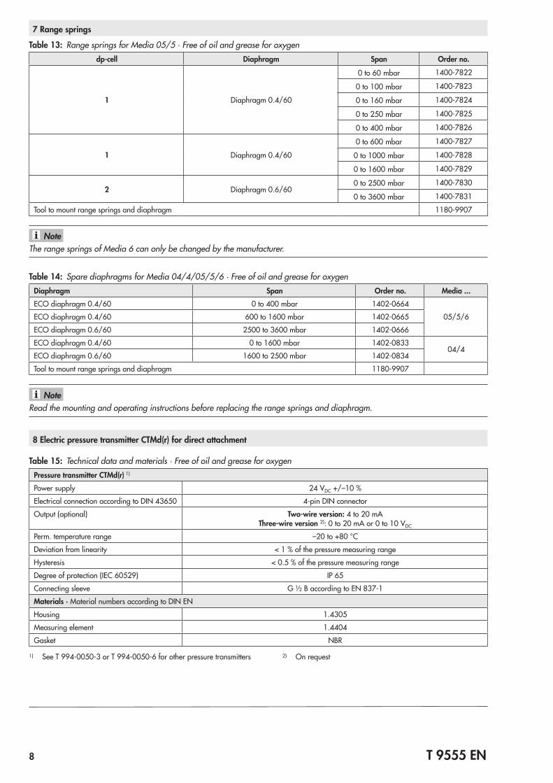
Table 13: Range springs for Media 05/5 · Free of oil and grease for oxygendp-cell Diaphragm Span Order no.
1 Diaphragm 0.4/60
0 to 60 mbar 1400-7822
0 to 100 mbar 1400-7823
0 to 160 mbar 1400-7824
0 to 250 mbar 1400-7825
0 to 400 mbar 1400-7826
1 Diaphragm 0.4/60
0 to 600 mbar 1400-7827
0 to 1000 mbar 1400-7828
0 to 1600 mbar 1400-7829
2 Diaphragm 0.6/600 to 2500 mbar 1400-7830
0 to 3600 mbar 1400-7831
Tool to mount range springs and diaphragm 1180-9907
The range springs of Media 6 can only be changed by the manufacturer.Note
7 Range springs
Table 14: Spare diaphragms for Media 04/4/05/5/6 · Free of oil and grease for oxygenDiaphragm Span Order no. Media ...ECO diaphragm 0.4/60 0 to 400 mbar 1402-0664
05/5/6ECO diaphragm 0.4/60 600 to 1600 mbar 1402-0665
ECO diaphragm 0.6/60 2500 to 3600 mbar 1402-0666
ECO diaphragm 0.4/60 0 to 1600 mbar 1402-083304/4
ECO diaphragm 0.6/60 1600 to 2500 mbar 1402-0834
Tool to mount range springs and diaphragm 1180-9907
Read the mounting and operating instructions before replacing the range springs and diaphragm.
8 Electric pressure transmitter CTMd(r) for direct attachment
Table 15: Technical data and materials · Free of oil and grease for oxygenPressure transmitter CTMd(r) 1)
Power supply 24 VDC +/–10 %
Electrical connection according to DIN 43650 4-pin DIN connector
Output (optional) Two-wire version: 4 to 20 mAThree-wire version 2): 0 to 20 mA or 0 to 10 VDC
Perm. temperature range –20 to +80 °C
Deviation from linearity < 1 % of the pressure measuring range
Hysteresis < 0.5 % of the pressure measuring range
Degree of protection (IEC 60529) IP 65
Connecting sleeve G ½ B according to EN 837-1
Materials · Material numbers according to DIN EN
Housing 1.4305
Measuring element 1.4404
Gasket NBR
1) See T 994-0050-3 or T 994-0050-6 for other pressure transmitters 2) On request
Note
T 9555 EN 9
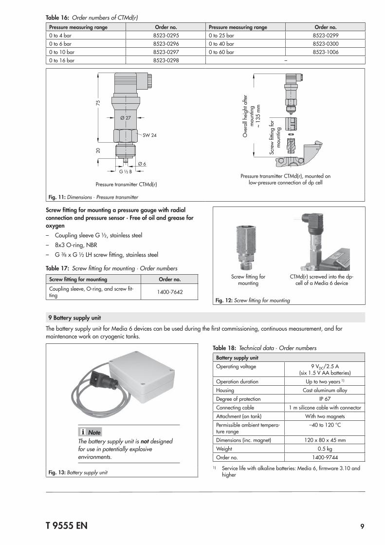
Table 16: Order numbers of CTMd(r)Pressure measuring range Order no. Pressure measuring range Order no.0 to 4 bar 8523-0295 0 to 25 bar 8523-02990 to 6 bar 8523-0296 0 to 40 bar 8523-03000 to 10 bar 8523-0297 0 to 60 bar 8523-10060 to 16 bar 8523-0298 –
7520
SW 24
G ½ B
Ø 6
Ø 27
Pressure transmitter CTMd(r)Pressure transmitter CTMd(r), mounted on
low-pressure connection of dp cell
Ove
rall
heig
ht a
fter
mou
ntin
g ~
135
mm
Scre
w fi
tting
for
mou
ntin
g
Fig. 11: Dimensions ∙ Pressure transmitter
Screw fitting for mounting a pressure gauge with radial connection and pressure sensor · Free of oil and grease for oxygen – Coupling sleeve G ½, stainless steel – 8x3 O-ring, NBR – G 3/8 x G ½ LH screw fitting, stainless steel
Table 17: Screw fitting for mounting · Order numbers
Screw fitting for mounting Order no.
Coupling sleeve, O-ring, and screw fit-ting 1400-7642
Screw fitting for mounting
CTMd(r) screwed into the dp-cell of a Media 6 device
Fig. 12: Screw fitting for mounting
The battery supply unit is not designed for use in potentially explosive environments.
Note
Fig. 13: Battery supply unit
Table 18: Technical data ∙ Order numbersBattery supply unitOperating voltage 9 VDC/2.5 A
(six 1.5 V AA batteries)Operation duration Up to two years 1)
Housing Cast aluminum alloyDegree of protection IP 67Connecting cable 1 m silicone cable with connectorAttachment (on tank) With two magnetsPermissible ambient tempera-ture range
–40 to 120 °C
Dimensions (inc. magnet) 120 x 80 x 45 mmWeight 0.5 kgOrder no. 1400-9744
1) Service life with alkaline batteries: Media 6, firmware 3.10 and higher
9 Battery supply unit
The battery supply unit for Media 6 devices can be used during the first commissioning, continuous measurement, and for maintenance work on cryogenic tanks.
10 T 9555 EN
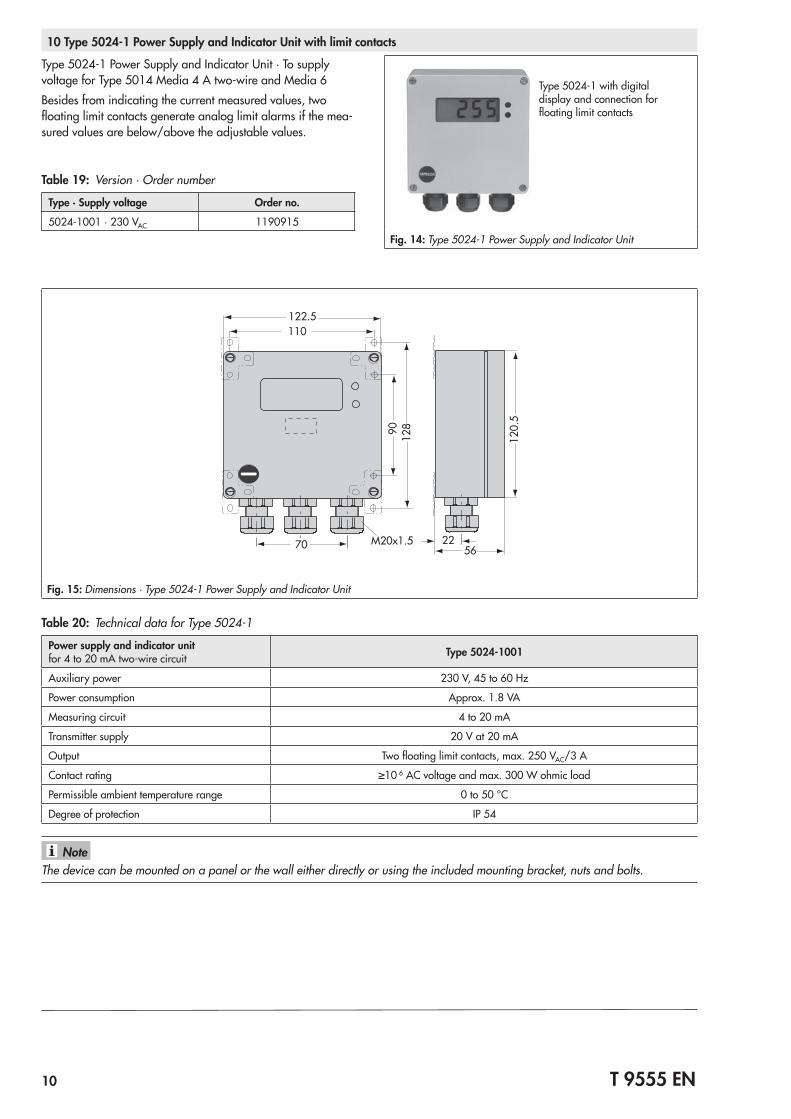
10 Type 5024-1 Power Supply and Indicator Unit with limit contacts
Type 5024-1 Power Supply and Indicator Unit · To supply voltage for Type 5014 Media 4 A two-wire and Media 6Besides from indicating the current measured values, two floating limit contacts generate analog limit alarms if the mea-sured values are below/above the adjustable values.
Table 19: Version · Order number
Type · Supply voltage Order no.
5024-1001 · 230 VAC 1190915
Type 5024-1 with digital display and connection for floating limit contacts
Fig. 14: Type 5024-1 Power Supply and Indicator Unit
70 M20x1.5 2256
120.
5
122.5110
12890
Fig. 15: Dimensions · Type 5024-1 Power Supply and Indicator Unit
Table 20: Technical data for Type 5024-1
Power supply and indicator unit for 4 to 20 mA two-wire circuit Type 5024-1001
Auxiliary power 230 V, 45 to 60 Hz
Power consumption Approx. 1.8 VA
Measuring circuit 4 to 20 mA
Transmitter supply 20 V at 20 mA
Output Two floating limit contacts, max. 250 VAC/3 A
Contact rating ≥10 6 AC voltage and max. 300 W ohmic load
Permissible ambient temperature range 0 to 50 °C
Degree of protection IP 54
The device can be mounted on a panel or the wall either directly or using the included mounting bracket, nuts and bolts.Note
T 9555 EN 11
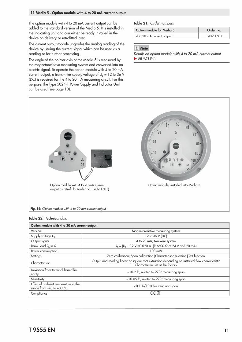
11 Media 5 · Option module with 4 to 20 mA current output
The option module with 4 to 20 mA current output can be added to the standard version of the Media 5. It is installed in the indicating unit and can either be ready installed in the device on delivery or retrofitted later.The current output module upgrades the analog reading of the device by issuing the current signal which can be used as a reading or for further processing.The angle of the pointer axis of the Media 5 is measured by the magnetoresistive measuring system and converted into an electric signal. To operate the option module with 4 to 20 mA current output, a transmitter supply voltage of UB = 12 to 36 V (DC) is required for the 4 to 20 mA measuring circuit. For this purpose, the Type 5024-1 Power Supply and Indicator Unit can be used (see page 10).
Table 21: Order numbers
Option module for Media 5 Order no.
4 to 20 mA current output 1402-1501
Details on option module with 4 to 20 mA current output u EB 9519-1.
Note
Option module with 4 to 20 mA current output as retrofit kit (order no. 1402-1501)
Option module, installed into Media 5
Fig. 16: Option module with 4 to 20 mA current output
Table 22: Technical data
Option module with 4 to 20 mA current outputVersion Magnetoresistive measuring systemSupply voltage UB 12 to 36 V (DC)Output signal 4 to 20 mA, two-wire systemPerm. load RB in Ω RB = (UB – 12 V)/0.020 A|(R ≤600 Ω at 24 V and 20 mA)Power consumption 103 mWSettings Zero calibration|Span calibration|Characteristic selection|Test function
Characteristic Output and reading linear or square root extraction depending on installed flow characteristic Characteristic set at the factory
Deviation from terminal-based lin-earity <±0.2 %, related to 270° measuring span
Sensitivity <±0.05 %, related to 270° measuring spanEffect of ambient temperature in the range from –40 to +80 °C <0.1 %/10 K for zero and span
Compliance
12 T 9555 EN
12 TROVIS-VIEW configuration software · Connecting cable · Memory pen · Modular adapter
TROVIS-VIEW 6661 configuration softwareA Media 6 Digital Transmitter can be operated over a com-puter using the TROVIS-VIEW Configuration and Operator In-terface.The operator interface contains all functions of Media 6, to-gether with the required information. The system can be con-figured and operated entirely over a computer.Media 6 needs to be connected to the serial interface at COM 1 to 225 of the computer using the appropriate connecting cable.
TROVIS-VIEW can be downloaded free of charge from our website at www.samson.de > Services > Software > TROVIS-VIEW.
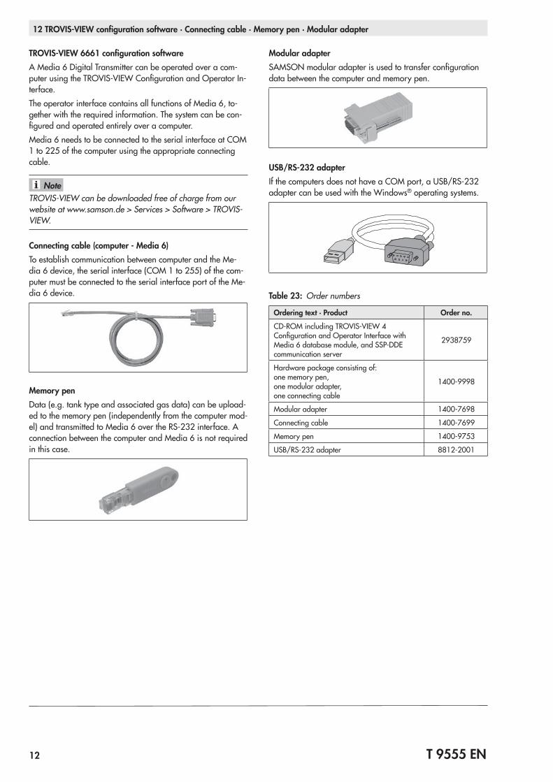
Connecting cable (computer - Media 6)To establish communication between computer and the Me-dia 6 device, the serial interface (COM 1 to 255) of the com-puter must be connected to the serial interface port of the Me-dia 6 device.
Memory penData (e.g. tank type and associated gas data) can be upload-ed to the memory pen (independently from the computer mod-el) and transmitted to Media 6 over the RS-232 interface. A connection between the computer and Media 6 is not required in this case.
Note
Modular adapterSAMSON modular adapter is used to transfer configuration data between the computer and memory pen.
USB/RS-232 adapterIf the computers does not have a COM port, a USB/RS-232 adapter can be used with the Windows® operating systems.
Table 23: Order numbers
Ordering text · Product Order no.
CD-ROM including TROVIS-VIEW 4 Configuration and Operator Interface with Media 6 database module, and SSP-DDE communication server
2938759
Hardware package consisting of: one memory pen, one modular adapter, one connecting cable
1400-9998
Modular adapter 1400-7698
Connecting cable 1400-7699
Memory pen 1400-9753
USB/RS-232 adapter 8812-2001
T 9555 EN 13
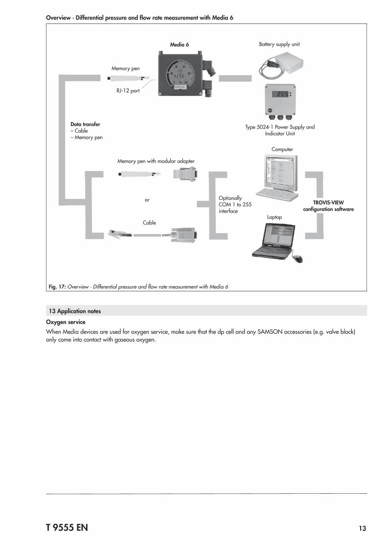
Overview · Differential pressure and flow rate measurement with Media 6
Cable
Data transfer – Cable – Memory pen
Memory pen with modular adapter
RJ-12 port
Computer
Battery supply unit
or
Memory pen
Type 5024-1 Power Supply and Indicator Unit
Laptop
Media 6
Optionally COM 1 to 255 interface
TROVIS-VIEW configuration software
Fig. 17: Overview · Differential pressure and flow rate measurement with Media 6
13 Application notes
Oxygen serviceWhen Media devices are used for oxygen service, make sure that the dp cell and any SAMSON accessories (e.g. valve block) only come into contact with gaseous oxygen.


Specifications subject to change without notice
SAMSON AG · MESS- UND REGELTECHNIK Weismüllerstraße 3 · 60314 Frankfurt am Main, Germany Phone: +49 69 4009-0 · Fax: +49 69 4009-1507 [email protected] · www.samson.de T 9555 EN 20
18-0
2-26
· En
glish