Embed Size (px)
Citation preview

Features
DI-720 For General Purpose Use
DI-730 For Electric Motor/Generator Maintenance, and Troubleshooting in
Mills, Locomotion, and DC Drive System Applications
Standard Printer Port, Optional USB or Ethernet
Interface
14-Bit Resolution
DI-720 and DI-730 Series
DATAQ Instruments, Inc. • 241 Springside Drive • Akron, Ohio 44333 • Tel: 330-668-1444 • Email: [email protected] • www.dataq.com
The DI-720 Series and DI-730 Series are families of instruments that offer 14-bit resolution and 150-200kHz waveform recording capability. They communicate through your PC's parallel port or an optional Ethernet or USB interface. Use the DI-720 for general purpose applications where pre amplified signals are acquired. Examples are process monitoring, and many medical research applications. Use the DI-730 for wide dynamic range measurements, especially those involving AC or DC electric motors. Examples include paper, aluminum, and steel mills; high speed trains; and rail and seagoing locomotion. The high sample rate, exceptional isolation, and CMR characteristics of the DI-730 make it very well suited for maintenance and troubleshooting of DC drive systems. Other applications include RPM measurements from motor/generators, supply voltage and current measurements, and field current measurements from drive-roll, braking, and take-up motors. See pages 11 and 12 for Application Close ups.The Ethernet communication option connects DI-720 and DI-730 Series products to any local area network (LAN). Direct Internet access is also possible. This patented (US 7,792,139 B2) communication option uses standard CAT-5 cable to yield continuous data acquisition throughput rates up to 180kHz. Multiple DI-720/730 products (each equipped with an Ethernet interface) may be daisy-chained together to form an ad-hoc extended network of autonomous, yet fully synchronous data acquisition stations. Each station can sample at a different rate (up to 180kHz throughput) and still maintain full synchronization. Station separation can be as far as 100 meters.
DI-730 Offers Isolation, Wide Dynamic Measurement RangeThe 8-channel DI-730 Series features a measurement range of ±10mV to ±1000VDC (or peak AC) over six gain ranges with ±1000V channel-to-channel and input-to-output isolation. Replace entire racks of isolation amps, high and low voltage amps, and data acquisition subsystems with one, portable, lightweight instrument. Channel-to-channel isolation protects delicate control circuits, computer equipment, and personnel from high common mode voltages.
DI-720 Offers Lowest Cost Per Channel of Any Competing ProductThe DI-720 Series accepts 32 high-level or signal conditioned analog inputs in a single-ended mode or 16 inputs in a differential input mode. The high-level inputs are typically low impedance, preconditioned signals in the range of 1.25 to 10VFS. Channel expansion up to 240 channels is possible with expanders.
Printer Port, USB, or Ethernet InterfaceDI-720 and -730 instruments are available with printer port, Ethernet, and universal serial bus (USB) communication interfaces. All instruments have a 25-pin male printer port connector for EPP, bidirectional, or standard mode parallel port communication with your PC. Options add Ethernet communication capability with a RJ45 connector, or a USB port for universal serial bus communication. The optional communication interfaces sacrifice the standard PP mode and cannot be used concurrently with the printer port.
Synchronized Distributed Ethernet Data AcquisitionDaisy chain multiple DI-720 and/or DI-730 Ethernet units for a fully synchronous distributed Ethernet data acquisition system. See pages 8-10 for more information.
Burst Sampling A/DConnect to DC or near DC signals like temperature, generator-based RPM, or other slow process variables. Sample rates well into the sub-Hertz range are possible. Use for high speed applications such as modulated DC drives and other AC waveform situations.
High Resolution CapabilityDI-720 and -730 instruments apply 14 bits of resolution to your measurement task. A special version of the DI-720 with full 16-bit accuracy is available. Contact DATAQ Instruments for details.
Easy to Connect & UseAll instruments connect in seconds to your PC's parallel port, Ethernet connector, or USB port. See I/O options on page 4.
WinDaq Software IncludedWinDaq is free with the purchase of every instrument. WinDaq is restricted to a maximum throughput of 240 Hz when recording to disk (when 2 or more channels are enabled). Increase record-to-disk rates with and unlock code (WinDaq/Pro or WinDaq/Pro+).Use WinDaq Waveform Browser (free) to review, measure, compare, and analyze the waveform file after it has been recorded by WinDaq acquisition software.See page 5 for a closer look at WinDaq Software and other compatible software packages.
Top: DI-720Bottom: DI-730

DI-720 Input Configuration
330-668-1444 2 www.dataq.com
Access to channels 1 through 16 and I/O accessories via 37-pin D type, male connector.
Access to channels 17 through 32 and expansion ac-cessories via 37-pin D type, male connector.
All channels support a measurement range of ±10VFS. Single-ended, differential, and gain factors of 1, 2, 4, and 8 are programmable per channel.
DI-720 Front Panel
DI-720 Analog Input Block Diagram

Each of eight fully differential and isolated channels support ±10mV to ±1000V measurements across six programmable ranges. Access is via re-cessed banana sockets.
DI-730 Front Panel
DI-730 Analog Input Block Diagram
DI-730 Input Configuration
www.dataq.com 3 330-668-1444
Analog expansion port* Optional USB port 5-pin DIN power connector (9-36 VDC) Power switch
Parallel port (standard on all models) ACTIVE LED indicates data acquisition activity
POWER LED indicates power is applied *16SE/8DI Inputs. Programmable ±1.25 to 10 VFS.
DI-720 and DI-730 Rear Panel I/O (USB and PP)

Models DI-720-P or DI-730-PParallel Port
Maximum Sample Speed**EPP/720: 200 kHzEPP/730: 150 kHzBidirectional: 80 kHzStandard: 40 kHz
Benefits• Connects to PCs with no Ethernet or USB
interface.
USBEthernetModels DI-720-EN or DI-730-EN Models DI-720-USB or DI-730-USB
DI-720 and DI-730 Interface Options
Maximum Distance6 feet (2 meters)
Maximum Distance16 feet (5 meters)
Maximum Sample Speed**DI-720: 180 kHzDI-730: 150 kHz
Maximum Sample Speed**DI-720: 200 kHz***
DI-730: 150 kHz
*Expandable to over 1 mile (2 kilometers) with commonly available repeaters.**Maximum stream-to-disc rate using WINDAQ software on a 350 MHz Pentium II machine running Windows 98. Triggered storage rates will be faster. Contact DATAQ Instruments to determine expected maximum sample rates for other machine speeds and operating systems.***Using Last Point Acquisition Mode. Other modes are limited to 150 kHz.
Benefits• Connects to any established Ethernet
network.• Inexpensive cabling• TCP/IP internet accessible• Daisy-chain multiple units for a fully
synchronous distributed data acquisition system
Benefits• Plug and play configuration• "Hot swap" capability
Maximum Distance*328 feet/segment (100 meters/segment)
330-668-1444 4 www.dataq.com
10/1
00ba
se-T

www.dataq.com 5 330-668-1444
Use the WinDaq Waveform Browser to review, com-pare, qualify, and export recorded waveform data in ways you've never seen on a PC. Compress an entire session's recording to one screen width for a bird's eye view, then expand around an area of interest for a clos-er look. Use cursors to precisely measure amplitudes and timing. Move to any event marker in the file with the click of a mouse button. Then access WinDaq’s wealth of analysis tools to gain further insight. And you can do it all immediately, without the burden of programming.
WinDaq…The Most Widely Used Turnkey Test Instrumentation Software*
Review…
Record analog channel data using WinDaq’s continuous recording mode, or its triggered mode with selectable trigger level, slope, and pre- and post-trigger times. WinDaq automatically time- and date-stamps, then streams acquired data and your commented event markers to disk—acquire as much data as you need. At the same time, WinDaq reveals on your monitor a real time graphical display of any or all channels, so you can easily chart your progress, identify critical events, and plan your next action. No other product gives you WinDaq’s power, speed, and flexibility. That’s why it’s the most widely used turnkey software package for PC-based test instrumentation.
Record…
and Analyze the Results.Waveform interpretation is easy with our built-in analysis functions. Apply frequency and filtering analysis with the WinDaq Waveform Browser's FFT and DFT functions. Or analyze any range of waveform data with its statistics function. Use X-Y plotting to examine the relationships of one channel to another. You'll gain insights you never thought possible. Advanced CODAS allows additional software analysis functions such as waveform integration, differentiation, arithmetic operations, peak detection, and more. Then export waveform graphics or data to any other application.
* Source: Test & Measurement World Market Insight Study, PC-based Test Instrumentation, May 1998

330-668-1444 6 www.dataq.com
Ethernet Block Diagram
Ethernet Interface* Close-upOur third generation Ethernet interface offers a number of advantages over USB and printer port alternatives. Of course, the Ethernet option allows CAT-5 cable lengths up to 100 meters without hubs over a local area network (LAN), as well as access from any loca-tion using the Internet with a properly configured network. But Ethernet interfaces also allow multiple DI-720/-730 products to be connected together for channel expansion. Data acquired across multiple units are acquired synchronously, meaning that samples fall within a definable time window with constant latency. For example, the torque, load and rpm of multiple rolling stations in a rolling mill, each instrumented with a DI-730 product, may be precisely correlated as an aid to maintenance and troubleshooting, and the distance between each station can be as great as 100 meters. Finally, the synchronized and distributed nature of these products with an Ethernet interface is simplified by allowing common CAT-5 cable to be strung between units in a daisy-chain fashion without the need for external hubs or switches or costly custom cables.
Analog expansion port* 5-pin DIN power connector (9-36 VDC) Power switch
Parallel port (standard on all models) ACTIVE LED indicates data acquisition activity
POWER LED indicates power is applied
*16SE/8DI Inputs. Programmable ±1.25 to 10 VFS.
Optional Ethernet interface allows multiple units to be daisy-chained
Ethernet Rear Panel
*Patented (US 7,792,139 B2)

www.dataq.com 7 330-668-1444
3
Ethernet Expansion Examples1. Local, Synchronous ExpansionConnect and stack multiple Ethernet versions of DI-720 Series instruments (DI-720 or DI-722) or the DI-730 together in any combination. Synchronization between units is guaranteed, and the PC may be local to 100 meters distant from the data acquisition hardware.
2. Add Isolated Amplifier BackpacksAdd expansion backpacks like the DI-75B and DI-78B to the mix. Doing so preserves synchronization, increases channel count, and brings the full spectrum of 5B and 8B isolation amplifiers to bear on your measurement tasks.
3. Distributed, Synchronous ExpansionCreate multiple measurement stations of any combination of DI-720, -722, or -730 instruments, with or without amplifier backpacks. Individual stations may be separated from adjacent stations by up to 100 meters to yield virtually unlimited overall lengths, with synchronization guaranteed across the entire span.
KeyA = DI-720, -722, or -730 Unit
B = Isolated Expansion Backpack (DI-78B or DI-75B)
Connects to Ethernet Port on PC or LAN
Daisy-chain Cables
Connects to next Unit in the Chain
(All cables can be up to 100 meters)
1
2

Primary Synchronous Data Acquisition CustomersPrimary CustomersPrimary customers include:• Those who need to acquire data from a remote location where it is not practical or
economical to leave a computer.• Users who want a path to easily expand their measurement channels at some future
point.• Customers who need synchronized data acquisition measurements across data
acquisition units.• Troubleshooters/designers who need fine, synchronous measurements to well within
millisecond resolution.• Customers who need fast, synchronized measurements across multiple, distributed
data acquisition stations spaced as far as 100 meters between stations.
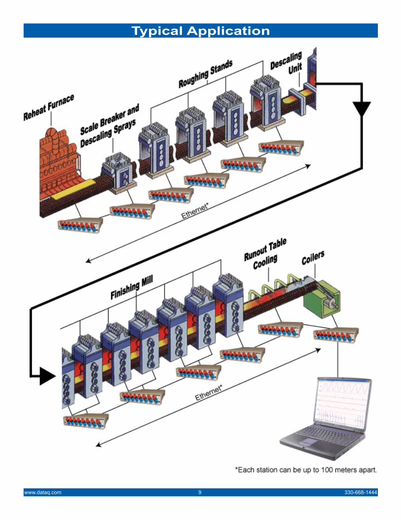
Typical ApplicationsTypical application examples include maintenance and troubleshooting applications in:Large web offset and printing press machineryHydraulic metalworking pressesInjection moulding machinesReversing millsSteel and aluminum rolling mills including:• Roughing mills• Intermediate mills• Finishing mills• Cold rolling tandem mills• Cluster mills• Temper rolling mills• Coilers
Paper mills, including:• Wire processes• Presses• Dryers• Size presses• Calendars• Reelers• Unwinders and slitters
Structural wind/weather audits on large structures:• Tall buildings• Long bridge spans• Floating platforms like oil rigs• Extended length vessels like super
tankers• Any size structure that requires a
distributed, yet synchronized approach to data acquisition
PLC fine tuning and troubleshooting to detect:• Electrical sequencing variations and
flaws• Mechanical valve actuation latencies• Motor timing conflicts• Hydraulic spikes or drop outs
Typical MeasurementsTypical measurements include:
Mechanical properties measurements, including:• Load/pressure/stress• Vibration• Temperature• Flow• Distance/movement• Tension/compression
AC/DC drive/motor measurements, including:• Speed (armature voltage)• Speed regulation (tach vs. set point)• Torque (armature current)• Acceleration/deceleration times• IR compensation• Load balancing
330-668-1444 8 www.dataq.com

330-668-1444 10 www.dataq.com
CAT-5 Ethernet Cable*
*Up to 100 meters.
Software for Synchronous Data Acquisition
To next DI-720 or DI-730Series Instrument
Record and Playback all data synchronously. The TCP/IP Manager (above) allows you to record from all daisy-chained instruments at the click of a button. The WinDaq Wave-form Navigator (below) allows you to view all your data perfectly aligned in time.
Application Close up: Steel rolling mill
DI-730 Series Data Acquisition Hardware
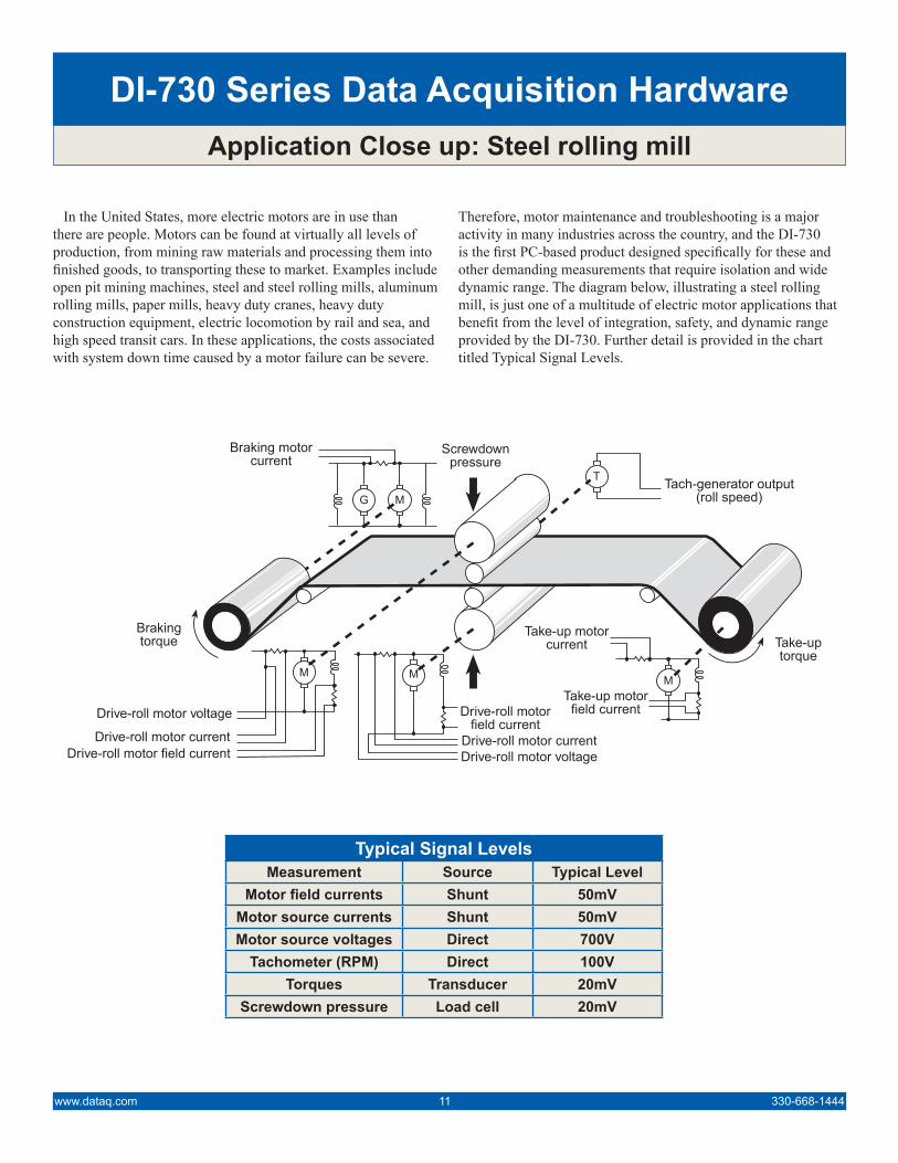
In the United States, more electric motors are in use than there are people. Motors can be found at virtually all levels of production, from mining raw materials and processing them into finished goods, to transporting these to market. Examples include open pit mining machines, steel and steel rolling mills, aluminum rolling mills, paper mills, heavy duty cranes, heavy duty construction equipment, electric locomotion by rail and sea, and high speed transit cars. In these applications, the costs associated with system down time caused by a motor failure can be severe.
Therefore, motor maintenance and troubleshooting is a major activity in many industries across the country, and the DI-730 is the first PC-based product designed specifically for these and other demanding measurements that require isolation and wide dynamic range. The diagram below, illustrating a steel rolling mill, is just one of a multitude of electric motor applications that benefit from the level of integration, safety, and dynamic range provided by the DI-730. Further detail is provided in the chart titled Typical Signal Levels.
Typical Signal LevelsMeasurement Source Typical Level
Motor field currents Shunt 50mVMotor source currents Shunt 50mVMotor source voltages Direct 700V
Tachometer (RPM) Direct 100VTorques Transducer 20mV
Screwdown pressure Load cell 20mV
www.dataq.com 11 330-668-1444
G M
M
T
Take-uptorque
Brakingtorque
Tach-generator output(roll speed)
Take-up motorcurrent
Take-up motorfield current
M
Drive-roll motor voltageDrive-roll motor current
Drive-roll motorfield current
M
Drive-roll motor field currentDrive-roll motor current
Drive-roll motor voltage
Braking motorcurrent
Screwdownpressure
Application Close up: DC drive systems
DI-730 Series Data Acquisition Hardware
A popular method used to achieve variable motor speeds employs an AC modulation technique that is applied to DC motors. Such an approach, referred to as a DC drive system, places tremendous demands on the instruments used to measure the process.
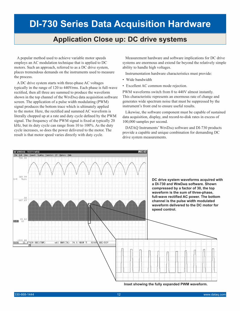
A DC drive system starts with three-phase AC voltages typically in the range of 120 to 440Vrms. Each phase is full-wave rectified, then all three are summed to produce the waveform shown in the top channel of the WinDaq data acquisition software screen. The application of a pulse width modulating (PWM) signal produces the bottom trace which is ultimately applied to the motor. Here, the rectified and summed AC waveform is literally chopped up at a rate and duty cycle defined by the PWM signal. The frequency of the PWM signal is fixed at typically 20 kHz, but its duty cycle can range from 10 to 100%. As the duty cycle increases, so does the power delivered to the motor. The result is that motor speed varies directly with duty cycle.
Measurement hardware and software implications for DC drive systems are enormous and extend far beyond the relatively simple ability to handle high voltages.
Instrumentation hardware characteristics must provide:• Wide bandwidth • Excellent AC common mode rejection. PWM waveforms switch from 0 to 440V almost instantly. This characteristic represents an enormous rate of change and generates wide spectrum noise that must be suppressed by the instrument’s front end to ensure useful results.
Likewise, the software component must be capable of sustained data acquisition, display, and record-to-disk rates in excess of 100,000 samples per second.
DATAQ Instruments’ WinDaq software and DI-730 products provide a capable and unique combination for demanding DC drive system measurements.
DC drive system waveforms acquired with a DI-730 and WinDaq software. Shown compressed by a factor of 30, the top waveform is the sum of three-phase, full-wave rectified AC power. The bottom channel is the pulse width modulated waveform delivered to the DC motor for speed control.
Inset showing the fully expanded PWM waveform.
330-668-1444 12 www.dataq.com

www.dataq.com 13 330-668-1444
DI-720/DI-730 Series Software AccessoriesSoftware Purpose Availability Application
ActiveX Controls Programming FREE
Programming environment for Windows programming languages such as Visual BASIC, C++, Delphi, and LabVIEW.
Please Note: High sample rates (over 150K) may not be achievable using the ActiveX Controls. The ActiveX Controls DO NOT support synchronous data acquisition.
WINDAQRecording/Playback
and Analysis FREE
True multitasking waveform recording and analysis software for the Windows environment. Record with the WINDAQ Acquisition software while analyzing data with the WINDAQ Waveform Browser software (includes frequency and filtering analysis with FFT and DFT func-tions, statistical analysis, and X-Y plotting capabilities).Supplied with every hardware purchase, WINDAQ sup-ports hardware-capable stream-to-disk rates for one chan-nel. Two or more channels are restricted to a maximum stream-to-disk throughput rate of 240Hz.
WINDAQ/ProUnlock Code
Recording/Playback and Analysis Extra-Cost Option Unlock Code for WINDAQ that adds the ability to sample
at the highest allowable speed of the hardware.
WINDAQ/Pro+Unlock Code
Recording/Playback and Analysis Extra-Cost Option
Unlock Code WINDAQ that adds the ability to sample at the highest allowable speed of the hardware and the abil-ity to sample different channels at different rates.
WINDAQ/XL WINDAQ to Excel Bridge Extra-Cost Option Allows you to port data, in real time and without pro-
gramming, to Microsoft Excel.
XControls Display Extra-Cost Option
Allows you to display virtual instrumentation directly on your computer without programming. Supports a multitude of angular and sliding gages, thermocouple columns, and much more. May be used directly in Microsoft Excel without programming (requires WINDAQ/XL). May also be accessed from any Windows programming language.
Advanced CODAS Analysis Extra-Cost Option
Sophisticated analysis add-on to WINDAQ Software. Functions include differentiator, integrator, rectifier, mov-ing average filter, arithmetic operations, peak and valley detector, and report generator.
WINDAQ Waveform Browser Navigator Analysis FREE
Waveform playback software allowing you to browse all synchronized distributed waveforms acquired using multiple Ethernet DI-720 and/or DI-730 products and analyze waveform data with WINDAQ Waveform Browser software (includes frequency and filtering analysis with FFT and DFT functions, statistical analysis, and X-Y plot-ting capabilities).
Order No. Description
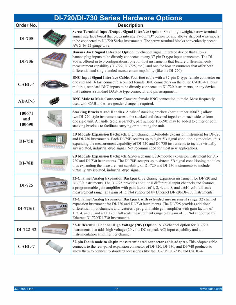
DI-705Screw Terminal Input/Output Signal Interface Option. Small, lightweight, screw terminal signal interface board that plugs into any 37-pin “D” connector and allows stripped wire inputs to be connected to DI-720 Series instruments. The screw terminal blocks conveniently accept AWG 16-22 gauge wire.
DI-706
Banana Jack Signal Interface Option. 32 channel signal interface device that allows banana plug inputs to be directly connected to any 37-pin D-type input connectors. The DI-706 is offered in two configurations; one for host instruments that feature differential-only measurement capability (DI-722, DI-725, etc.), and one for host instruments that offer both differential and single-ended measurement capability (like the DI-720).
CABL-4BNC Input Signal Interface Cable. Four foot cable with a 37-pin D-type female connector on one end and 16 fast connect/disconnect female BNC connectors on the other. CABL-4 allows multiple, standard BNC inputs to be directly connected to DI-720 instruments, or any device that features a standard DAS-16 type connector and pin assignment.
ADAP-3 BNC Male to Male Connector. Converts female BNC connection to male. Most frequently used with CABL-4 where gender change is required.
100671and
100690
Stacking Brackets and Handles. A pair of stacking brackets (part number 100671) allow two DI-720-style instrument cases to be stacked and fastened together on each side to form one rigid unit. A handle (sold separately, part number 100690) may be added to either or both stacking brackets to facilitate carrying or mounting the unit.
DI-75B5B Module Expansion Backpack. Eight channel, 5B-module expansion instrument for DI-720 and DI-730 instruments. Each DI-75B accepts up to eight 5B signal conditioning modules, thus expanding the measurement capability of DI-720 and DI-730 instruments to include virtually any isolated, industrial-type signal. Not recommended for most new applications.
DI-78B8B Module Expansion Backpack. Sixteen channel, 8B-module expansion instrument for DI-720 and DI-730 instruments. The DI-78B accepts up to sixteen 8B signal conditioning modules, thus expanding the measurement capability of DI-720 and DI-730 instruments to include virtually any isolated, industrial-type signal.
DI-72532-Channel Analog Expansion Backpack. 32 channel expansion instrument for DI-720 and DI-730 instruments. The DI-725 provides additional differential input channels and features a programmable gain amplifier with gain factors of 1, 2, 4, and 8, and a ±10 volt full scale measurement range (at a gain of 1). Not supported by Ethernet DI-720/DI-730 Instruments.
DI-725/E
32-Channel Analog Expansion Backpack with extended measurement range. 32 channel expansion instrument for DI-720 and DI-730 instruments. The DI-725 provides additional differential input channels and features a programmable gain amplifier with gain factors of 1, 2, 4, and 8, and a ±10 volt full scale measurement range (at a gain of 1). Not supported by Ethernet DI-720/DI-730 Instruments.
DI-722-3232-Differential Channel High Voltage (20V) Option. A 32-channel option for DI-720 instruments that adds high voltage (20 volts DC or peak AC) input capability and an instrumentation amplifier per channel.
CABL-737-pin D-sub male to 40-pin mass terminated connector cable adapter. This adapter cable connects to the rear-panel expansion connector of DI-720, DI-730, and DI-740 products to allow them to connect to standard accessories like the DI-705, DI-205, and CABL-4.
330-668-1444 14 www.dataq.com
DI-720/DI-730 Series Hardware Options

DI-720 and DI-730 Specifications
Ordering GuideDescription Order No. Description Order No.32 channel data acquisition system featuring 14-bit measure-ment resolution, EPP support, up to 200kHz sampling rate, and a maximum measurement range of ±10VFS. Includes AC adapter, parallel communications cable, WinDaq waveform recording software and playback and analysis software.
DI-720-P
8 channel (plus 16SE/8DI), high voltage waveform recording system featuring channel-to-channel isolation and six measure-ment ranges from ±10mV to ±1000V full scale. Includes AC adapter, parallel communications cable, WinDaq waveform recording software and playback and analysis software.
DI-730-P
Same as DI-720-P, but with Ethernet communications option. DI-720-EN Same as DI-730-P, but with Ethernet communications option. DI-730-ENSame as DI-720-P, but with USB communications option. DI-720-USB Same as DI-730-P, but with USB communications option. DI-730-USB
Analog InputsNumber of Channels DI-720:
DI-730:32SE/16DI (software selectable per channel)8 wide range and 16SE/8DI general purpose
Input Type BipolarIsolation (DI-730 only) ±1000V input-to-output and channel-to-channel
Analog Resolution 14-bit, 1 part in 16,384Maximum normal mode
voltage (VNM)DI-720: VNM + VCM < 30V PeakDI-730: 1500VDC or peak AC
Maximum common modevoltage (VCM)
DI-720: VNM + VCM < 30V PeakDI-730: 1000VDC or peak AC
Sample Throughput Rate (Printer Port)
Standard: 40,000 Hz maxBi-directional: 80,000 Hz maxEPP: 200,000 Hz (DI-720) max or 150,000 Hz (DI-730) max
Sample Throughput Rate (USB)
DI-720: 200,000 Hz maxDI-730: 150,000 Hz max
Sample Throughput Rate (Ethernet)
DI-720: 180,000 Hz maxDI-730: 150,000 Hz max
Measurement Range Full Scale
DI-720 Series InstrumentsGain Setting Measurement Range
1 ±10V2 ±5V3 ±2.5V4 ±1.25V
DI-730 Series Instruments(8 wide range channels)
Gain Setting Measurement Range*1 ±1000V10 ±100V100 ±10V1000 ±1V10000 ±100mV100000 ±10mV
DI-730 Series Instruments(general purpose channels)
Gain Setting Measurement Range
1 ±10V2 ±5V3 ±2.5V4 ±1.25V
Common Mode Rejection DI-720: 80dB min @ Av=1DI-730: 100dB min @ DC to 60Hz
Accuracy Vin ≤ 800V ±(0.25% of full scale range ±100µV)Vin > 800V ±(0.5% of full scale range)
Channel-to-Channel Crosstalk -75 dB @100kHz (50 KHz for DI-722) into 100 Ω unbalanced
Input Impedance DI-720: 1MΩ resistor tied to GND on input CHDI-730: 10MΩ for all ranges
Max jitter between synched units 5 microseconds
* Usable over +8159 to -8160 ADC counts.
Analog frequency re-sponse (each channel): Model Measurement
Range Response
DI-720 All -3 db @ >125.0 kHzDI-722 All -3 db @ >70.0 kHzDI-730 ±1000, 100, 10, 1 V -3 db @ 5.0 kHz
±100 mV -3 db @ 4.50 kHz±10 mV -3 db @ 1.30 kHz
Expansion channels -3 db @ >125.0 kHz
Interface OptionsStandard, bi-directional, or EPP parallel port. Optional Ethernet or USB
Analog OutputsNumber of Channels DI-720: Two buffered analog outputs
DI-730: One analog outputResolution 12-bit, 1 part in 4096 @ 250kHz
Output Voltage Range ±10VOutput Impedance 10Ω
Sample Throughput Rate 40,000 standard; 80,000 bi-directional; 200,000 EPP Hz max (software selectable per channel)
Output Offset Voltage 1 bit max @ 1kHz sample rateGain Error 1 part in 16,384 @ 1kHz
Digital I/O (DI-720 Only)Capacity 8 each input and output
Compatibility TTL-compatibleMax source current 0.4mA @ 2.4V
Max sink current 8mA @ 0.5VDigital termination 4.7kΩ pull-up to +5VDC
TriggeringPre-trigger length 64,000 samples
Post-trigger length 64,000 samplesTrigger channel any channel
Trigger level hysteresis 8-bit (256 counts)
Intelligent Oversampling ModesSignal averaging, maximum value, minimum value, last point, frequency, and RMS
Physical/EnvironmentalDimensions 7.29W × 9L × 1.52H inches
Operating Temperature 0 to 70°CStorage Temperature -55 to 150°C
Humidity 0 - 90% non condensingWeight DI-720: 3 lbs.
DI-730: 5 lbs.
Supported SoftwareActiveX Controls; WinDaq; WinDaq/XL; WinDaq Waveform Browser
Analog Input Connector TypeDI-720 37-pin male “D” connectorDI-730 safety banana socket - 1 pair per channel (wide
range channels)
www.dataq.com 15 330-668-1444

241 Springside DriveAkron, Ohio 44333
Submit a Support Ticket at:www.dataq.com/ticket/
Data Acquisition Product Links(click on text to jump to page)Data Acquisition | Data Logger
DATAQ, the DATAQ logo and WinDaq are registered trademarks of DATAQ Instruments, Inc. All rights reserves. Copyright © 2014 DATAQ Instruments, Inc.The information on this data sheet is subject to change without notice.

![2020 ] 730 Fiscale 2020.pdf · MODELLO 730 PRECOMPILATO MODELLO 730 PRECOMPILATO Anche quest’anno l’Agenzia delle entrate dal 5 Maggio mette a disposizione di dipendenti e pensionati](https://img.dokumen.tips/doc/110x75/60486f224998504d934ab483/2020-fiscale-2020pdf-modello-730-precompilato-modello-730-precompilato-anche.jpg)


![Locomotion [2014]](https://img.dokumen.tips/doc/110x75/5564e3eed8b42ad3488b4e94/locomotion-2014.jpg)