Embed Size (px)
Citation preview

Installation and Operation Manual DHW
HT#
059
106-
00C
Energy SaverDomestic Hot Water Boiler or Direct or Indirect Water Heater and Recirculating Pump Control with Setback Schedule
WaRnIngThis Heat-Timer control is strictly an operating control; it should never be used as a primary limit or safety control. all equipment
must have its own certified limit and safety controls required by local codes. The installer must verify proper operation and correct any
safety problems prior to the installation of this Heat-Timer control.
DHW Energy Saver
Boiler Pump
6 7 8 9
COM
3 4 5A GND B
16VAC
1 2~ ~
Typical Wiring for PlatinumSerial Panel RS485 Plug
2 DHW Energy Saver Installation and Configuration Manual
HT#
059
106-
00C
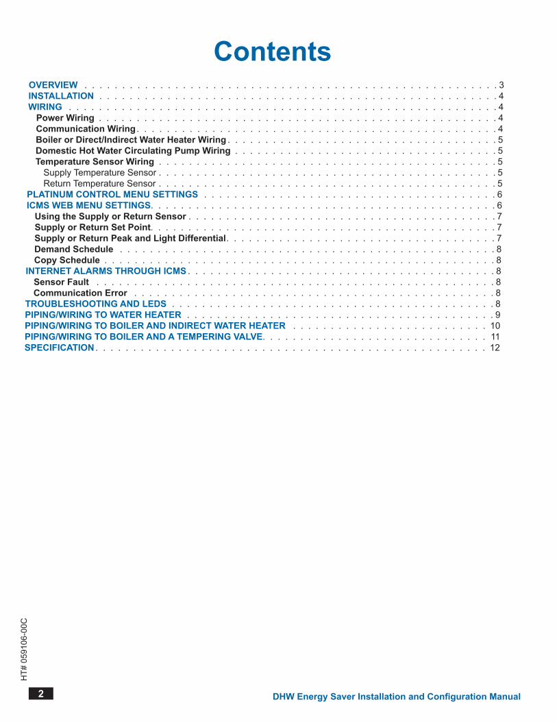
ContentsOvERvIEW 3InSTallaTIOn 4WIRIng 4
Power Wiring 4Communication Wiring 4Boiler or Direct/Indirect Water Heater Wiring 5Domestic Hot Water Circulating Pump Wiring 5Temperature Sensor Wiring 5
Supply Temperature Sensor 5Return Temperature Sensor 5
PlaTInuM COnTROl MEnu SETTIngS 6ICMS WEB MEnu SETTIngS 6
using the Supply or Return Sensor 7Supply or Return Set Point 7Supply or Return Peak and light Differential 7Demand Schedule 8Copy Schedule 8
InTERnET alaRMS THROugH ICMS 8Sensor Fault 8Communication Error 8
TROuBlESHOOTIng anD lEDS 8PIPIng/WIRIng TO WaTER HEaTER 9PIPIng/WIRIng TO BOIlER anD InDIRECT WaTER HEaTER 10PIPIng/WIRIng TO BOIlER anD a TEMPERIng valvE 11SPECIFICaTIOn 12

DHW Energy Saver Installation and Configuration Manual 3
HT#
059
106-
00C
OverviewTheDHW(DomesticHotWater)EnergySaverconnectstoaHeat-TimerRINetPlatinumseriescontrol(allMPC,MPCQ,HWR,HWRQ,SRCRINetPlatinumcontrolswithsoftwareversion7.05orhigher)tooperateaboilerordirect/indirectwaterheaterandaDHWcirculatingpumpbasedontwosetpoints.Onesetpointisfortheboilerandtheotherisforthepump.TwosensorsconnectedtothePlatinumRINet(Internetcommunicationcapablecontrol)areused.AuxTemp0sensormeasuresthedomestichotboilersupplytemperature.AuxTemp1sensormeasuresthedomesticrecirculatinglinereturntemperature.
AlltheDHWEnergySaversettingscanbeviewedandadjustedthroughthePlatinumcontrolmenusorthePlatinumcontrolpagesonICMSwebsite(http://www.htcontrols.com).Eachofthesupplyandreturntemperatureshaveasetpointandapeakdemandandlightloadconditiondifferentials.Thisoffersbetteroperationandsavingsthanonedifferential.Asthegoalistoreduceboiler/waterheaterandpumpoperationduringlightperiods.Thatcanbeachievedbyhavingslightlylongerboiler/waterheaterrunperiodsandlongeroffperiodsusingalargerdifferential.WhenthesupplytemperaturedropsbelowtheSupplySetPointanddifferential,theControlwillenergizetheboileroutput.TheboileroutputwillremainenergizeduntilthesupplytemperaturereachestheSupplySetPoint.WhenthereturntemperaturedropsbelowtheReturnSetPointlessthedifferential,theControlwillenergizethecirculatingpumpoutput.ThepumpoutputwillremainenergizeduntilthereturntemperaturereachestheReturnSetPoint.
WaRnIng• Make sure Recirculating Pump control does not adversely affect other equipment. I.e. tempering valve.• Make sure the boiler/water heater can operate properly at the lowest desired differential adjustment.
ThePlatinumcontrolhasaseparateDHWEnergySaverweeklyDay/NightschedulethatcanbesetusingtheInternetICMSwebsiteorthroughthePlatinumcontrolmenu.Itoffers4peakand4lightloadperiodsforeachdayoftheweek.Wheninthepeakperiod,thePlatinumcontrolwillusethePeakDifferentialsetting.Wheninthelightusageperiod,thePlatinumcontrolwillusetheLightDifferentialsetting.TheLightDifferentialmustbegreaterthanthePeakDifferentialtoprovidelongerboilerorpumpruntimeandlongeroffperiods.
DHW Energy Saver
Boiler Pump
6 7 8 9
COM
3 4 5A GND B
16VAC
1 2~ ~
Typical Wiring for PlatinumSerial Panel RS485 Plug
16 VAC(transformer
Provided)
Communication toHeat-Timer
Platinum Control
DHW boiler andDHW circulating
pump output relays
4 DHW Energy Saver Installation and Configuration Manual
HT#
059
106-
00C
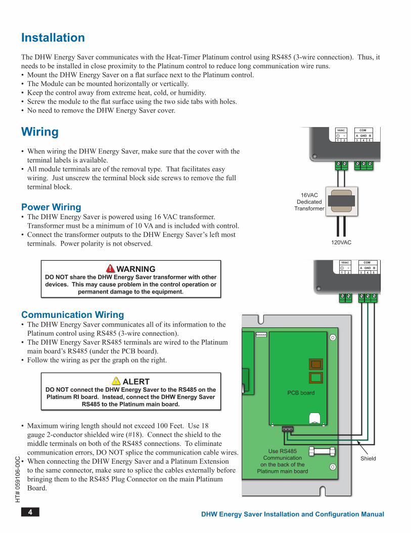
InstallationTheDHWEnergySavercommunicateswiththeHeat-TimerPlatinumcontrolusingRS485(3-wireconnection).Thus,itneedstobeinstalledincloseproximitytothePlatinumcontroltoreducelongcommunicationwireruns.• MounttheDHWEnergySaveronaflatsurfacenexttothePlatinumcontrol.• TheModulecanbemountedhorizontallyorvertically.• Keepthecontrolawayfromextremeheat,cold,orhumidity.• Screwthemoduletotheflatsurfaceusingthetwosidetabswithholes.• NoneedtoremovetheDHWEnergySavercover.
Wiring• WhenwiringtheDHWEnergySaver,makesurethatthecoverwiththeterminallabelsisavailable.
• Allmoduleterminalsareoftheremovaltype.Thatfacilitateseasywiring.Justunscrewtheterminalblocksidescrewstoremovethefullterminalblock.
DHW Energy Saver
Boiler Pump
6 7 8 9
COM
3 4 5A GND B
16VAC
1 2~ ~
120VAC
16VACDedicatedTransformerPower Wiring
• TheDHWEnergySaverispoweredusing16VACtransformer.Transformermustbeaminimumof10VAandisincludedwithcontrol.
• ConnectthetransformeroutputstotheDHWEnergySaver’sleftmostterminals.Powerpolarityisnotobserved.
WaRnIngDO nOT share the DHW Energy Saver transformer with other devices. This may cause problem in the control operation or
permanent damage to the equipment.
Communication Wiring• TheDHWEnergySavercommunicatesallofitsinformationtothePlatinumcontrolusingRS485(3-wireconnection).
• TheDHWEnergySaverRS485terminalsarewiredtothePlatinummainboard’sRS485(underthePCBboard).
• Followthewiringasperthegraphontheright.
alERTDO nOT connect the DHW Energy Saver to the RS485 on the Platinum RI board. Instead, connect the DHW Energy Saver
RS485 to the Platinum main board.
• Maximumwiringlengthshouldnotexceed100Feet.Use18gauge2-conductorshieldedwire(#18).ConnecttheshieldtothemiddleterminalsonbothoftheRS485connections.Toeliminatecommunicationerrors,DONOTsplicethecommunicationcablewires.
• WhenconnectingtheDHWEnergySaverandaPlatinumExtensiontothesameconnector,makesuretosplicethecablesexternallybeforebringingthemtotheRS485PlugConnectoronthemainPlatinumBoard.
DHW Energy Saver
Boiler Pump
6 7 8 9
COM
3 4 5A GND B
16VAC
1 2~ ~
Use RS485Communication
on the back of thePlatinum main board
PCB board
Shield
DHW Energy Saver Installation and Configuration Manual 5
HT#
059
106-
00C
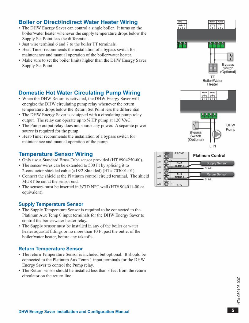
Boiler or Direct/Indirect Water Heater Wiring• TheDHWEnergySavercancontrolasingleboiler.Itturnsontheboiler/waterheaterwheneverthesupplytemperaturedropsbelowtheSupplySetPointlessthedifferential.
• Justwireterminal6and7totheboilerTTterminals.• Heat-Timerrecommendstheinstallationofabypassswitchformaintenanceandmanualoperationoftheboiler/waterheater.
• MakesuretosettheboilerlimitshigherthantheDHWEnergySaverSupplySetPoint.
DHW Energy Saver
Boiler Pump
6 7 8 9
COM
3 4 5A GND B
16VAC
1 2~ ~
TTBoiler/Water
Heater
BypassSwitch
(Optional)
Domestic Hot Water Circulating Pump Wiring• WhentheDHWReturnisactivated,theDHWEnergySaverwillenergizetheDHWcirculatingpumprelaywheneverthereturntemperaturedropsbelowtheReturnSetPointlessthedifferential
• TheDHWEnergySaverisequippedwithacirculatingpumprelayoutput.Therelaycanoperateupto⅛HPpumpat120VAC.
• ThePumpoutputrelaydoesnotsourceanypower.Aseparatepowersourceisrequiredforthepump.
• Heat-Timerrecommendstheinstallationofabypassswitchformaintenanceandmanualoperationofthepump.
DHW Energy Saver
Boiler Pump
6 7 8 9
COM
3 4 5A GND B
16VAC
1 2~ ~
DHWPump
L N
BypassSwitch
(Optional)
Temperature Sensor Wiring• OnlyuseaStandardBrassTubesensorprovided(HT#904250-00).• Thesensorwirescanbeextendedto500Ftbysplicingitto2-conductorshieldedcable(#18/2Shielded)(HT#703001-01).
• ConnecttheshieldatthePlatinumcontrolcircledterminal.TheshieldMUSTbecutatthesensorend.
• Thesensorsmustbeinsertedin⅜”IDNPTwell(HT#904011-00orequivalent).
AUXTEMP 0
AUXTEMP 1
A1
A2
A3
A4
A5
A6
A7
A8
A9
A10
A11
A12
AUXTEMP 2
A13
A14
A15
A16
A17
A18
NETWORK
PROVE
SHUTDOWN
OUTTEMP
T
T
T
T
PRESS4-20 mA
S
+
S
Shield
Supply Sensor
Shield
Return Sensor
Platinum Control
Supply Temperature Sensor• TheSupplyTemperatureSensorisrequiredtobeconnectedtothePlatinumAuxTemp0inputterminalsfortheDHWEnergySavertocontroltheboiler/waterheaterrelay.
• TheSupplysensormustbeinstalledinanyoftheboilerorwaterheateraquastatfittingsornomorethan10Ftpasttheoutletoftheboiler/waterheater,beforeanytakeoffs.
Return Temperature Sensor• ThereturnTemperatureSensorisincludedbutoptional.ItshouldbeconnectedtothePlatinumAuxTemp1inputterminalsfortheDHWEnergySavertocontrolthePumprelay.
• TheReturnsensorshouldbeinstalledlessthan3feetfromthereturncirculatoronthereturnline.
6 DHW Energy Saver Installation and Configuration Manual
HT#
059
106-
00C
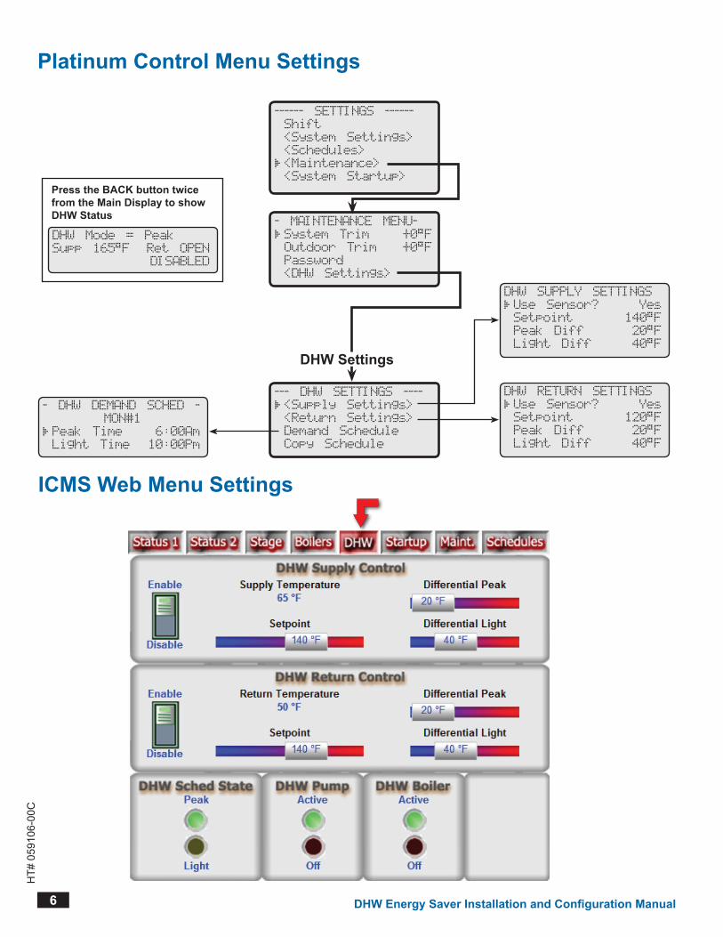
Platinum Control Menu Settings
------ SETTINGS ------
Shift
<System Settings>
<Schedules>
<Maintenance>
<System Startup>
- MAINTENANCE MENU-
System Trim +0 F
Outdoor Trim +0 F
Password
<DHW Settings>
--- DHW SETTINGS ----
<Supply Settings>
<Return Settings>
Demand Schedule
Copy Schedule
DHW Settings
DHW SUPPLY SETTINGS
Use Sensor? Yes
Setpoint 140 F
Peak Diff 20 F
Light Diff 40 F
DHW RETURN SETTINGS
Use Sensor? Yes
Setpoint 120 F
Peak Diff 20 F
Light Diff 40 F
- DHW DEMAND SCHED -
MON#1
Peak Time 6:00Am
Light Time 10:00Pm
ICMS Web Menu Settings
DHW Mode = Peak
Supp 165 F Ret OPEN
DISABLED
Press the BaCK button twice from the Main Display to show DHW Status

DHW Energy Saver Installation and Configuration Manual 7
HT#
059
106-
00C
using the Supply or Return SensorYes, No Default: NoSELECTMaintenance/DHW Settings/Supply Settings/Use Sensor Supply SensorSELECTMaintenance/DHW Settings/Return Settings/Use Sensor Return Sensor• ByactivatingtheSupplySensorfeature,thePlatinumcontrolwillutilizeAuxTemp0inputastheSupplySensor.
• ByactivatingtheReturnSensorfeature,thePlatinumcontrolwillutilizeAuxTemp1inputastheReturnSensor.
• AnyofthetwofeaturescanbeenabledeitherusingthePlatinumcontrolmenusorthePlatinumcontrolICMSwebpageat(http://www.htcontrols.com).
USE SUPPLY SENSOR
No
Yes
USE RETURN SENSOR
No
Yes
Supply or Return Set PointBoiler is adjustable from 60°F/16°C to 200F°/93°C Boiler Default: 140°F/60°CPump is adjustable from 60°F/16°C to 200F°/93°C Pump Default: 120°F/49°CSELECTMaintenance/DHW Settings/Supply Settings/Setpoint Supply SensorSELECTMaintenance/DHW Settings/Return Settings/Setpoint Return Sensor• TheSupplySetPointdeterminesthemaximumtemperatureatwhichtheboiler/waterheaterrelaywillde-energize.ItisthemaximumDHWtargettemperaturetheDHWEnergySaverwilltrytoachieve.Therelaywillenergizewheneverthesupplytemperaturedropsbelowthissetpointlessthedifferential.Seenextsetting.
• TheReturnSetPointdeterminesthemaximumtemperatureatwhichtheDHWpumprelaywillde-energize.Thecirculatingpumprelaywillenergizewheneverthereturntemperaturedropsbelowthissetpointlessthedifferential.Seenextsetting.
DHW SUPPLY SETPOINT
140 F
[ ]
DHW RETURN SETPOINT
120 F
[ ]
Supply or Return Peak and light DifferentialPeak is adjustable from 5F°/3C° to 100F°/56C° Peak Default: 10F°/6C°Light is adjustable from 5F°/3C° to 100F°/56C° Light Default: 20F°/11C°SELECTMaintenance/DHW Settings/Supply Settings/Peak Diff or Light Diff Supply SensorSELECTMaintenance/DHW Settings/Return Settings/Peak Diff or Light Diff Return Sensor• Anyofthedifferentialsissubtractedfromthesetpointtodeterminethetemperatureatwhichtheboiler/waterheaterorpumprelaywillenergize.
• TheDHWEnergySaverhastwoindependentdifferentialsforeachofthesupplyandreturn.ThePeakDifferentialisusedtokeepatightcontrolovertheDHWtemperatureduringheavyusage.ThisdifferentialisusedwhentheDHWScheduleisinthePeakperiod.ItsvaluemustbelessthanorequaltotheLightDifferentialforthesamesensor.
• TheLightDifferentialisusedduringthenight,lowDHWusage,orwhenatightcontrolofthetemperatureisnotrequired.Itallowstheboilerorpumprelaytoturnonforaslightlylongerperiod.However,duetothereducedusage,therelaywillremainoffforamuchlongerperiod.ThistypeofdifferentialisusedwhentheDHWScheduleisintheLightperiod.ItsvaluemustbegreaterthanorequaltothePeakDifferentialforthesamesensor.
DHW SUPPLY PEAK DIFF
20 F
[ ]
DHW SUPPLY LIGHT DIFF
40 F
[ ]
DHW RETURN PEAK DIFF
20 F
[ ]
DHW RETURN LIGHT DIFF
40 F
[ ]

8 DHW Energy Saver Installation and Configuration Manual
HT#
059
106-
00C
Demand ScheduleSELECTMaintenance/DHW Settings/Demand Schedule• ThePeakandLightDemandScheduleactivatestherespectivedifferential.Eachdayoftheweekhas4PeakTimesand4LightTimesthatcanbesetdifferently.
• WhenintheDHWSchedule,pressingtheNEXTbuttononthePlatinumcontroldisplaysthenextScheduleentry.
• PressingtheDAYbuttononthePlatinumcontroldisplaysthenextweekdayentry.• DomestichotwaterDemandSchedulecanbeaccessedontheICMSwebsitebyselectingSchedulesfromthePlatinumcontrolLiveSessionthenselectingtheDHWDemand.
- DHW DEMAND SCHED -
MON#1
Peak Time 6:00Am
Light Time 10:00Pm
Copy ScheduleSELECTMaintenance/DHW Settings/Copy Schedule• AftersettingtheMondaySchedule,theusercancopyitssettingstotherestofthedaysoftheweek.Thisreducessetuptime.
- DHW DEMAND SCHED -
Copy Mon Schedule
to all other days
(SELECT to Execute)
Internet alarms Through ICMSSensor Fault• IfanyofthesensorsfailedorweredisconnectedfromthePlatinumControl,thecontrolwillenergizetherespectiverelay.Makesurethattheboiler/waterheaterhasitsoperatingandlimitcontrolsinstalledandabletocontroltheboiler/waterheatertemperatureduringsensorfailuretoavoidhazardoussituations.
• Tosetupanalarmdeliveryforasensorfaultsituation,selectthesensorontheICMSwebsite.SelectAlarmDeliverySetupandthenAddDeliveryfortheSensorFault.
WaRnIngThe boiler/water heater must have its operating and limit controls installed and wired in a way so that the Supply sensor fault or DHW Energy Saver communication Error will
not cause a hazardous situation. It is the responsibility of the installer to make sure of the system operation and users safety during sensor fault or communication error.
Heat-Timer recommends the installation of a precision tempering valve, ETv, or TMC to help protect the output from excessive temperatures.
Communication Error• IftheDHWEnergySaverlostitscommunicationtothePlatinumcontrolformorethan1minute,itwillenergizebothoutputrelays.Makesurethattheboiler/waterheaterhasitsoperatingandlimitcontrolsinstalledandabletocontroltheboiler/waterheatertemperatureduringCommunicationErrorstoavoidhazardoussituations.
Troubleshooting and lEDsWhentheDHWEnergySavercoverisremoved,severalLEDswillbeavailableforviewing.TheseLEDsareusedfordiagnosingandtroubleshootingmanycommunicationandrelayoperation.• ApowerRedLEDindicatesthattheunithasthepropervoltagetooperate.• AGreenLEDblinkseverysecondtoindicatethereiscommunicationbetweentheDHWEnergySaverandthePlatinumcontrol.Ifthatcommunicationfails,thisLEDwillkeepblinkingfor15secondsthenitwillturnoff.Afteranadditional45seconds,thecontrolwillenergizebothoutputrelays.
• EachoftheoutputrelayshasaRedLEDthatisturnedonwheneverthatrelayisenergized.
DHW Energy Saver Installation and Configuration Manual 9
HT#
059
106-
00C
DHW Energy Saver
Boiler Pump
6 7 8 9
COM
3 4 5B A GND
16VAC
1 2~ ~
Typical Wiring for PlatinumSerial Panel TS485 Plug
HWRPlatinum
MADE IN U.S.A.
PREV.(DEL)
SAFETYGROUNDMUST BE
CONNECTED
OUTTEMP
DHWCAL
AUXTEMP 0
AUXTEMP 1
MENU FUNCTIONS
SELECT enters menus or accepts changes
ADJUST selects menu items or changes settings
BACK returns to previous menu
DAY selects next day
PREV./NEXT steps through output status
PUMP
LIN
E
NE
UTR
AL
DAYHELP NEXT
PRESS TOSELECT
BACK
MON 12/28/04 10:43Am
ADJUST
A1
A2
A3
A4
A5
A6
A7
A8
A9
A10
A11
A12
AUXTEMP 2
DO NOT APPLY ANY VOLTAGETO SENSOR TERMINALS
A13
A14
A15
A16
A17
A18
NETWORK
PROVE
SHUTDOWN
SYSTEMTEMP
CLOSE
OPEN(BYPASS)
ALL SENSORS MUST BEGOLD SERIES SENSORS
INPUTS
ROUTE SENSOR AND AUXILIARY WIRESTHROUGH THIS KNOCKOUT ONLY
BURNER
MOTORIZEDVALVE
CLOSE OPENOPTION
1OPTION
2
T
T
T
TGT= 126oF
Cut= 55oF Day
OD= 31oF SYS= 125oF
AUTO
AUXCLOCK
PUMP BURNERMOTORIZED
VALVE
CLOSE OPEN OPTION1
OPTION2
AUXCLOCK
T
TC O R P O R A T I O N
R
2 3 4 5 5A 6 7 8 9 11 12 13 14 15 16 17
OUTPUT RATINGS:120VAC, 6A RESISTIVE1A PILOT DUTY15A TOTALFOR ALL CIRCUITS
INPUT RATINGS:115VAC 60Hz30VA MAX
USE COPPER WIRE,CLASS 1 WIRE ONLY
ENCLOSEDENERGY
MANAGEMENTEQUIPMENT
99RA
PREV.(DEL)
OUTTEMP
DHWCAL
AUXTEMP 0
AUXTEMP 1
PUMP
DAYHELP NEXT
PRESS TOSELECT
BACK
A9
A10
A11
A12
AUXTEMP 2
A13
A14
A15
A16
A17
A18
BURNER
MOTORIZEDVALVE
CLOSE OPENOPTION
1OPTION
2
T
T
T
TGT= 126oF
Cut= 55oF Day
OD= 31oF SYS= 125oF
AUXCLOCK
PUMP BURNERMOTORIZED
VALVE
CLOSE OPEN OPTION1
OPTION2
AUXCLOCK
T
5 5A 6 7 8 9 11 12 13 14 15 16 17
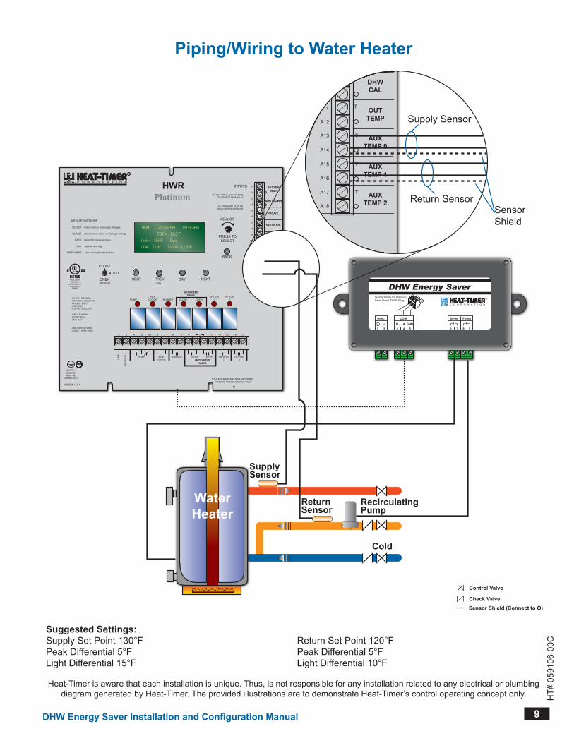
Supply Sensor
Return SensorSensorShield
RecirculatingPump
ReturnSensor
SupplySensor
WaterHeater
Cold
Suggested Settings:Supply Set Point 130°FPeak Differential 5°FLight Differential 15°F
Return Set Point 120°FPeak Differential 5°FLight Differential 10°F
Heat-Timer is aware that each installation is unique Thus, is not responsible for any installation related to any electrical or plumbing diagram generated by Heat-Timer The provided illustrations are to demonstrate Heat-Timer’s control operating concept only
Piping/Wiring to Water Heater
Control Valve
Check ValveSensor Shield (Connect to O)
10 DHW Energy Saver Installation and Configuration Manual
HT#
059
106-
00C
10
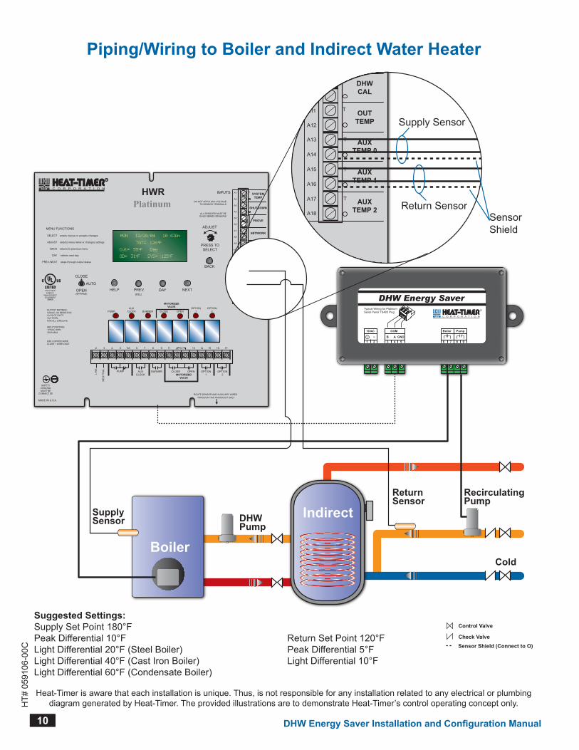
Piping/Wiring to Boiler and Indirect Water Heater
Suggested Settings:Supply Set Point 180°FPeak Differential 10°FLight Differential 20°F (Steel Boiler)Light Differential 40°F (Cast Iron Boiler)Light Differential 60°F (Condensate Boiler)
Return Set Point 120°FPeak Differential 5°FLight Differential 10°F
Heat-Timer is aware that each installation is unique Thus, is not responsible for any installation related to any electrical or plumbing diagram generated by Heat-Timer The provided illustrations are to demonstrate Heat-Timer’s control operating concept only
DHW Energy Saver
Boiler Pump
6 7 8 9
COM
3 4 5B A GND
16VAC
1 2~ ~
Typical Wiring for PlatinumSerial Panel TS485 Plug
HWRPlatinum
MADE IN U.S.A.
PREV.(DEL)
SAFETYGROUNDMUST BE
CONNECTED
OUTTEMP
DHWCAL
AUXTEMP 0
AUXTEMP 1
MENU FUNCTIONS
SELECT enters menus or accepts changes
ADJUST selects menu items or changes settings
BACK returns to previous menu
DAY selects next day
PREV./NEXT steps through output status
PUMP
LIN
E
NE
UTR
AL
DAYHELP NEXT
PRESS TOSELECT
BACK
MON 12/28/04 10:43Am
ADJUST
A1
A2
A3
A4
A5
A6
A7
A8
A9
A10
A11
A12
AUXTEMP 2
DO NOT APPLY ANY VOLTAGETO SENSOR TERMINALS
A13
A14
A15
A16
A17
A18
NETWORK
PROVE
SHUTDOWN
SYSTEMTEMP
CLOSE
OPEN(BYPASS)
ALL SENSORS MUST BEGOLD SERIES SENSORS
INPUTS
ROUTE SENSOR AND AUXILIARY WIRESTHROUGH THIS KNOCKOUT ONLY
BURNER
MOTORIZEDVALVE
CLOSE OPENOPTION
1OPTION
2
T
T
T
TGT= 126oF
Cut= 55oF Day
OD= 31oF SYS= 125oF
AUTO
AUXCLOCK
PUMP BURNERMOTORIZED
VALVE
CLOSE OPEN OPTION1
OPTION2
AUXCLOCK
T
TC O R P O R A T I O N
R
2 3 4 5 5A 6 7 8 9 11 12 13 14 15 16 17
OUTPUT RATINGS:120VAC, 6A RESISTIVE1A PILOT DUTY15A TOTALFOR ALL CIRCUITS
INPUT RATINGS:115VAC 60Hz30VA MAX
USE COPPER WIRE,CLASS 1 WIRE ONLY
ENCLOSEDENERGY
MANAGEMENTEQUIPMENT
99RA
PREV.(DEL)
OUTTEMP
DHWCAL
AUXTEMP 0
AUXTEMP 1
PUMP
DAYHELP NEXT
PRESS TOSELECT
BACK
A9
A10
A11
A12
AUXTEMP 2
A13
A14
A15
A16
A17
A18
BURNER
MOTORIZEDVALVE
CLOSE OPENOPTION
1OPTION
2
T
T
T
TGT= 126oF
Cut= 55oF Day
OD= 31oF SYS= 125oF
AUXCLOCK
PUMP BURNERMOTORIZED
VALVE
CLOSE OPEN OPTION1
OPTION2
AUXCLOCK
T
5 5A 6 7 8 9 11 12 13 14 15 16 17
Supply Sensor
Return SensorSensorShield
DHWPump
Boiler
RecirculatingPump
ReturnSensor
SupplySensor
Cold
Indirect
Control Valve
Check ValveSensor Shield (Connect to O)

DHW Energy Saver Installation and Configuration Manual 11
HT#
059
106-
00C
11
DHW Energy Saver
Boiler Pump
6 7 8 9
COM
3 4 5B A GND
16VAC
1 2~ ~
Typical Wiring for PlatinumSerial Panel TS485 Plug
HWRPlatinum
MADE IN U.S.A.
PREV.(DEL)
SAFETYGROUNDMUST BE
CONNECTED
OUTTEMP
DHWCAL
AUXTEMP 0
AUXTEMP 1
MENU FUNCTIONS
SELECT enters menus or accepts changes
ADJUST selects menu items or changes settings
BACK returns to previous menu
DAY selects next day
PREV./NEXT steps through output status
PUMP
LIN
E
NE
UTR
AL
DAYHELP NEXT
PRESS TOSELECT
BACK
MON 12/28/04 10:43Am
ADJUST
A1
A2
A3
A4
A5
A6
A7
A8
A9
A10
A11
A12
AUXTEMP 2
DO NOT APPLY ANY VOLTAGETO SENSOR TERMINALS
A13
A14
A15
A16
A17
A18
NETWORK
PROVE
SHUTDOWN
SYSTEMTEMP
CLOSE
OPEN(BYPASS)
ALL SENSORS MUST BEGOLD SERIES SENSORS
INPUTS
ROUTE SENSOR AND AUXILIARY WIRESTHROUGH THIS KNOCKOUT ONLY
BURNER
MOTORIZEDVALVE
CLOSE OPENOPTION
1OPTION
2
T
T
T
TGT= 126oF
Cut= 55oF Day
OD= 31oF SYS= 125oF
AUTO
AUXCLOCK
PUMP BURNERMOTORIZED
VALVE
CLOSE OPEN OPTION1
OPTION2
AUXCLOCK
T
TC O R P O R A T I O N
R
2 3 4 5 5A 6 7 8 9 11 12 13 14 15 16 17
OUTPUT RATINGS:120VAC, 6A RESISTIVE1A PILOT DUTY15A TOTALFOR ALL CIRCUITS
INPUT RATINGS:115VAC 60Hz30VA MAX
USE COPPER WIRE,CLASS 1 WIRE ONLY
ENCLOSEDENERGY
MANAGEMENTEQUIPMENT
99RA
PREV.(DEL)
OUTTEMP
DHWCAL
AUXTEMP 0
AUXTEMP 1
PUMP
DAYHELP NEXT
PRESS TOSELECT
BACK
A9
A10
A11
A12
AUXTEMP 2
A13
A14
A15
A16
A17
A18
BURNER
MOTORIZEDVALVE
CLOSE OPENOPTION
1OPTION
2
T
T
T
TGT= 126oF
Cut= 55oF Day
OD= 31oF SYS= 125oF
AUXCLOCK
PUMP BURNERMOTORIZED
VALVE
CLOSE OPEN OPTION1
OPTION2
AUXCLOCK
T
5 5A 6 7 8 9 11 12 13 14 15 16 17
Supply Sensor
Return SensorSensorShield
RecirculatingPump
Boiler
Boiler HeatExchanger
ReturnSensor
SupplySensor
TemperingValve
Cold
Control Valve
Check ValveSensor Shield (Connect to O)
Piping/Wiring to Boiler and a Tempering valve
Suggested Settings:Supply Set Point 180°FPeak Differential 10°FLight Differential 20°F (Steel Boiler)Light Differential 40°F (Cast Iron Boiler)
Return Set Point 120°FPeak Differential 5°FLight Differential 10°F
Heat-Timer is aware that each installation is unique Thus, is not responsible for any installation related to any electrical or plumbing diagram generated by Heat-Timer The provided illustrations are to demonstrate Heat-Timer’s control operating concept only
Control Valve
Check ValveSensor Shield (Connect to O)
20 New Dutch Lane, Fairfield, NJ 07004 Ph: (973) 575-4004 • Fax: (973) 575-4052
http://www.heat-timer.comHT#
059
106-
00C
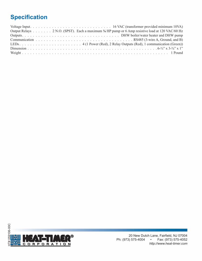
SpecificationVoltageInput . . . . . . . . . . . . . . . . . . . . . . . . . . . . . . 16VAC(transformerprovidedminimum10VA)OutputRelays . . . . . . . 2N.O.(SPST).Eachamaximum⅛HPpumpor6Ampresistiveloadat120VAC/60HzOutputs. . . . . . . . . . . . . . . . . . . . . . . . . . . . . . . . . . . . DHWboiler/waterheaterandDHWpumpCommunication . . . . . . . . . . . . . . . . . . . . . . . . . . . . . . . . . . . .RS485(3-wireA,Ground,andB)LEDs . . . . . . . . . . . . . . . . . . . . . . . 4(1Power(Red),2RelayOutputs(Red),1communication(Green))Dimension . . . . . . . . . . . . . . . . . . . . . . . . . . . . . . . . . . . . . . . . . . . . . . . . 6-¾”x3-⅝”x1”Weight . . . . . . . . . . . . . . . . . . . . . . . . . . . . . . . . . . . . . . . . . . . . . . . . . . . . . . 1Pound