Embed Size (px)
Citation preview

User
Manual
DeviceNet GTSUtilities Software
(Cat. No. 9240�GTSTK)
Allen�Bradley

Because of the variety of uses for the products described in thispublication, those responsible for the application and use of thiscontrol equipment must satisfy themselves that all necessary stepshave been taken to assure that each application and use meets allperformance and safety requirements, including any applicable laws,regulations, codes and standards.
The illustrations, charts, sample programs and layout examplesshown in this guide are intended solely for purposes of example.Since there are many variables and requirements associated with anyparticular installation, Allen-Bradley does not assume responsibilityor liability (to include intellectual property liability) for actual usebased upon the examples shown in this publication.
Allen-Bradley publication SGI-1.1, Safety Guidelines for theApplication, Installation, and Maintenance of Solid-State Control(available from your local Allen-Bradley office), describes someimportant differences between solid-state equipment andelectromechanical devices that should be taken into considerationwhen applying products such as those described in this publication.
Reproduction of the contents of this copyrighted publication, inwhole or in part, without written permission of Allen-BradleyCompany, Inc., is prohibited.
Throughout this manual we use notes to make you aware of safetyconsiderations:
!ATTENTION: Identifies information about practicesor circumstances that can lead to personal injury ordeath, property damage or economic loss.
Attention statements help you to:
• identify a hazard
• avoid the hazard
• recognize the consequences
Important: Identifies information that is critical for successfulapplication and understanding of the product.
DeviceNet is a trademark of Open DeviceNet Vendor Association (O.D.V.A.).Microsoft, MS-DOS, and PowerPoint are registered trademarks of Microsoft Corporation.Windows, Windows 95, and Windows NT are trademarks of Microsoft Corporation. WinDNet 16 is a trademark of Rockwell International.
Important UserInformation

Preface
Publication 1787�6.5.5 - August 1997
About This Manual
Use this manual as a guide when you install or use your1787-FLASH Tool software for the DeviceNet network.
Chapter 8Using Network
Chapter 1Chapter 2
Chapter 3
Chapter 4
Getting StartedSetting Up YourOnline Connection
Going Online
Chapter 5 Chapter 7
Using the Non�VolatileStorageUpdate Tool
Help with Trouble�shooting Tipsand DeviceNetOverview
Chapter 9Chapter 6
Using the DeviceNet System Configurator Software
Who and Mini Who Using theMessage Builder& Monitor
Loading the GTS Utilites Tools
This documentation is geared for control engineers, applicationengineers, or system integrators who need to modify and/ormanipulate the settings on their DeviceNet network.
The following conventions are used throughout the manual.
Type of text Example
Menu names UtilitiesText references to buttons OK
Text that you enter setup
What's in This Manual
Who ShouldRead This Manual
About the Conventions
About This ManualP–2
Publication 1787�6.5.5 - August 1997
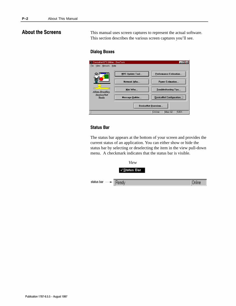
This manual uses screen captures to represent the actual software.This section describes the various screen captures you’ll see.
Dialog Boxes
Status Bar
The status bar appears at the bottom of your screen and provides thecurrent status of an application. You can either show or hide thestatus bar by selecting or deselecting the item in the view pull-downmenu. A checkmark indicates that the status bar is visible.
View
status bar
About the Screens

Important User Information -1. . . . . . . . . . . . . . . . . . . . . . . .
About This Manual P-1. . . . . . . . . . . . . . . . . . . . . . . . . . . . . . .
What's in This Manual P-1. . . . . . . . . . . . . . . . . . . . . . . . . . . . . . . .
Who Should Read This Manual P-1. . . . . . . . . . . . . . . . . . . . . . . . . .
About the Conventions P-1. . . . . . . . . . . . . . . . . . . . . . . . . . . . . . . .
About the Screens P-2. . . . . . . . . . . . . . . . . . . . . . . . . . . . . . . . . . .
Dialog Boxes P-2. . . . . . . . . . . . . . . . . . . . . . . . . . . . . . . . . . . . .
Status Bar P-2. . . . . . . . . . . . . . . . . . . . . . . . . . . . . . . . . . . . . . .
Getting Started 1-1. . . . . . . . . . . . . . . . . . . . . . . . . . . . . . . . .
What's in This Chapter 1-1. . . . . . . . . . . . . . . . . . . . . . . . . . . . . . . .
Meeting System Requirements 1-1. . . . . . . . . . . . . . . . . . . . . . . . . .
Installing the Software 1-2. . . . . . . . . . . . . . . . . . . . . . . . . . . . . . . .
Exiting the Installation 1-7. . . . . . . . . . . . . . . . . . . . . . . . . . . . . . . . .
Removing the Software from Your Hard Drive 1-7. . . . . . . . . . . . . . . .
Setting Up Your Online Connection 2-1. . . . . . . . . . . . . . . . . .
What's in This Chapter 2-1. . . . . . . . . . . . . . . . . . . . . . . . . . . . . . . .
About the DeviceNet Communication 2-1. . . . . . . . . . . . . . . . . . . . . .
Device Connections 2-2. . . . . . . . . . . . . . . . . . . . . . . . . . . . . . . . . .
Connecting the RS�232 Interface Module 2-4. . . . . . . . . . . . . . . . . . .
Power From Network 2-4. . . . . . . . . . . . . . . . . . . . . . . . . . . . . . .
Power From 9V DC Power�Supply Adapter 2-5. . . . . . . . . . . . . . .
Going Online 3-1. . . . . . . . . . . . . . . . . . . . . . . . . . . . . . . . . . .
What's in This Chapter 3-1. . . . . . . . . . . . . . . . . . . . . . . . . . . . . . . .
Going Online 3-1. . . . . . . . . . . . . . . . . . . . . . . . . . . . . . . . . . . . . . .
Operating Online 3-4. . . . . . . . . . . . . . . . . . . . . . . . . . . . . . . . . . . .
Going Offline 3-4. . . . . . . . . . . . . . . . . . . . . . . . . . . . . . . . . . . . . . .
Using the Non�Volatile Storage Update Tool 4-1. . . . . . . . . . . .
What's in This Chapter 4-1. . . . . . . . . . . . . . . . . . . . . . . . . . . . . . . .
About the NVS Update Tool 4-1. . . . . . . . . . . . . . . . . . . . . . . . . . . . .
Initializing and Updating a Device 4-2. . . . . . . . . . . . . . . . . . . . . . .
Using Network Who and Mini Who 5-1. . . . . . . . . . . . . . . . . . .
What's in This Chapter 5-1. . . . . . . . . . . . . . . . . . . . . . . . . . . . . . . .
Using Network Who 5-1. . . . . . . . . . . . . . . . . . . . . . . . . . . . . . . . . .
Using Mini Who 5-3. . . . . . . . . . . . . . . . . . . . . . . . . . . . . . . . . . . . .
Table of Contents

Table of Contentsii
Using the Message Builder & Monitor 6-1. . . . . . . . . . . . . . . .
What's in This Chapter 6-1. . . . . . . . . . . . . . . . . . . . . . . . . . . . . . . .
About the Message Builder & Monitor 6-1. . . . . . . . . . . . . . . . . . . . .
Using the Message Builder & Monitor 6-2. . . . . . . . . . . . . . . . . . . . . .
Loading the GTS Utilities Tools 7-1. . . . . . . . . . . . . . . . . . . . .
What's in This Chapter 7-1. . . . . . . . . . . . . . . . . . . . . . . . . . . . . . . .
About the Performance Estimation Tool 7-1. . . . . . . . . . . . . . . . . . . .
Loading the Performance Estimation Tool 7-1. . . . . . . . . . . . . . . . . . .
About the Power Estimation Tool 7-2. . . . . . . . . . . . . . . . . . . . . . . . .
Loading the Power Estimation Tool 7-3. . . . . . . . . . . . . . . . . . . . . . .
Help with Troubleshooting Tips and DeviceNet Overview 8-1.
What's in This Chapter 8-1. . . . . . . . . . . . . . . . . . . . . . . . . . . . . . . .
About the Troubleshooting Tips 8-1. . . . . . . . . . . . . . . . . . . . . . . . . .
Loading the Troubleshooting Tips 8-1. . . . . . . . . . . . . . . . . . . . . . . .
About the DeviceNet Overview 8-2. . . . . . . . . . . . . . . . . . . . . . . . . .
Loading the DeviceNet Overview 8-3. . . . . . . . . . . . . . . . . . . . . . . . .
Using the DeviceNet System Configurator Software 9-1. . . . .
What's in This Chapter 9-1. . . . . . . . . . . . . . . . . . . . . . . . . . . . . . . .
About the DSC Software 9-1. . . . . . . . . . . . . . . . . . . . . . . . . . . . . . .
Running the DSC Software 9-1. . . . . . . . . . . . . . . . . . . . . . . . . . . . .

Chapter 1
Publication 1787�6.5.5 - August 1997
Getting Started
Read this chapter to install the 9240-GTSTK Tool software into thehard drive of your computer.
For information on See page
Meeting system requirements 1-1
Installing the software 1-2
Exiting the installation 1-7
Removing the software from your hard drive 1-7
The software may be used with Windows version 3.1 or later,Windows for Workgroups version 3.11 or later, Windows 95 , orWindows NT . The software requires approximately 2 megabytesof hard-disk storage area.
This manual assumes that you are using Windows NT in itsdescription of system controls and procedures.
Companion files are required for the software to fully operate.
For this feature You need this software
Power calculation and performancecalculation spreadsheets
Microsoft Excel for Windowsversion 4.0 or later
Troubleshooting tips Microsoft Word for Windowsversion 6.0 or later
DeviceNet technologyoverview presentation
Microsoft PowerPoint for Windows orPowerPoint Viewer version 4.0 or later
What's in This Chapter
Meeting SystemRequirements

1–2 Getting Started
Publication 1787�6.5.5 - August 1997
Follow these directions to install the 9240-GTSTK Tool softwareonto the hard drive of your computer.
When the 9240-GTSTK Tool software is installed, the DeviceNetMonitor software is also installed. For more information on how touse the DeviceNet Monitor software, refer to the DeviceNet MonitorUser Manual, publication 1787-6.5.8.
1. Start Windows.
2. Insert the software disk into the 3.5” disk drive.
3. From the File menu in the Program Manager, choose Run.
File
4. Type a:setup.exe at the Command Line.
If you inserted the softwaredisk into another disk drive,use the appropriate driveletter instead of a:
5. Choose
You see this installation screen.
Installing the Software
1–3Getting Started
Publication 1787�6.5.5 - August 1997
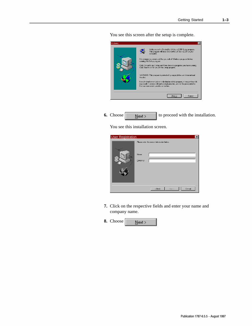
You see this screen after the setup is complete.
6. Choose to proceed with the installation.
You see this installation screen.
User RegistrationUser Registration
7. Click on the respective fields and enter your name andcompany name.
8. Choose

1–4 Getting Started
Publication 1787�6.5.5 - August 1997
You see this screen with the information you entered.
To Choose
Approve the information
Go back and make corrections
9.
1–5Getting Started
Publication 1787�6.5.5 - August 1997
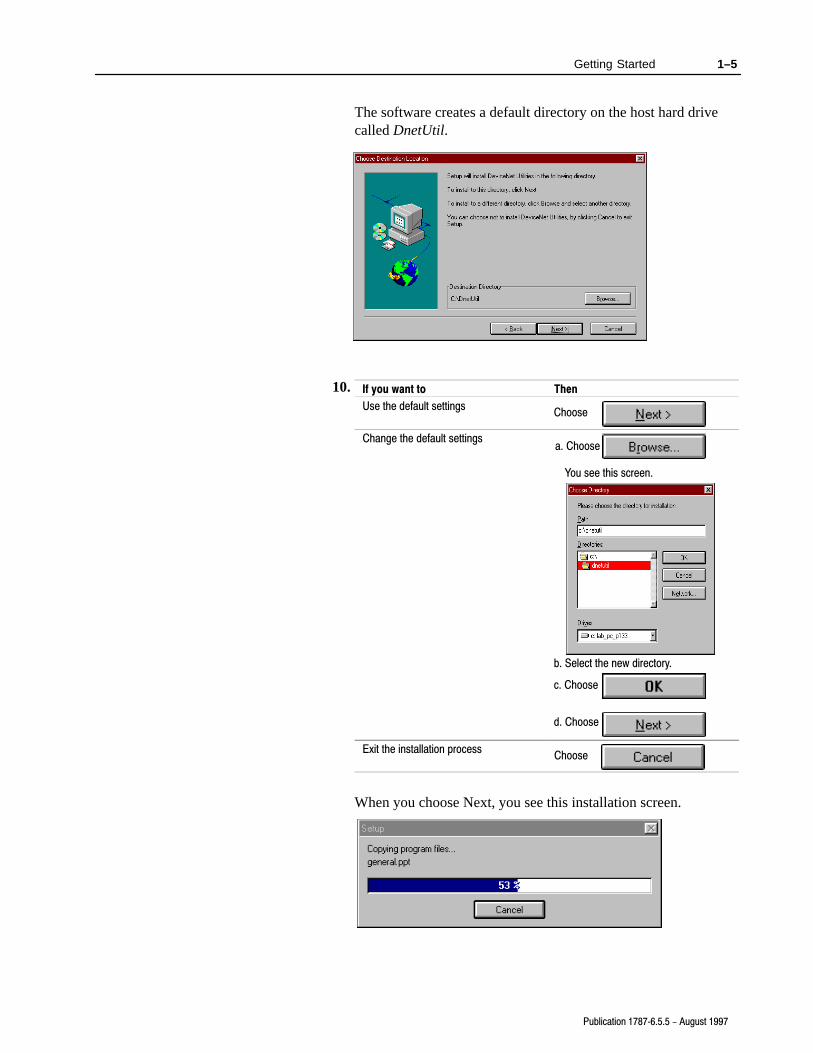
The software creates a default directory on the host hard drivecalled DnetUtil.
If you want to Then
Use the default settingsChoose
Change the default settingsa. Choose
You see this screen.
b. Select the new directory.
c. Choose
d. Choose
Exit the installation processChoose
When you choose Next, you see this installation screen.
10.

1–6 Getting Started
Publication 1787�6.5.5 - August 1997
Once the installation is complete, you see this message.
11.Choose
You see this screen.
The README file contains last minute changesto the software or the 9240�GTSTK Tool SoftwareInstallation Instructions.
To Choose
View the README file
Continue without viewing the README file
13.Choose
An icon now appears in your Program Manager.
12.

1–7Getting Started
Publication 1787�6.5.5 - August 1997
When available, you may stop the installation process by
choosing
You see this screen.
If you want to Choose
Return to the installation process
Exit the installation
You may delete the software from your host computer’s hard driveby simply deleting the directory in which you installed the program.
Exiting the Installation
Removing the Softwarefrom Your Hard Drive
Chapter 2
Publication 1787�6.5.5 - August 1997
Setting Up YourOnline Connection
Read this chapter to set up your online connection.
For information on See page
About the DeviceNet communication 2-1
Device connections NO TAG
Connecting the RS�232 interface module 2-4
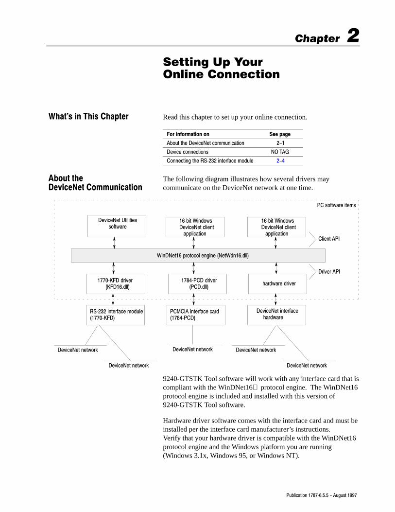
The following diagram illustrates how several drivers maycommunicate on the DeviceNet network at one time.
WinDNet16 protocol engine (NetWdn16.dll)
RS�232 interface module(1770�KFD)
1770�KFD driver (KFD16.dll)
DeviceNet interface hardware
DeviceNet network
DeviceNet Utilitiessoftware
PCMCIA interface card(1784�PCD)
DeviceNet network
DeviceNet network
DeviceNet network
DeviceNet network
PC software items
Client API
Driver API
16�bit WindowsDeviceNet client application
16�bit WindowsDeviceNet client application
hardware driver1784�PCD driver (PCD.dll)
9240-GTSTK Tool software will work with any interface card that iscompliant with the WinDNet16 protocol engine. The WinDNet16protocol engine is included and installed with this version of9240-GTSTK Tool software.
Hardware driver software comes with the interface card and must beinstalled per the interface card manufacturer’s instructions.Verify that your hardware driver is compatible with the WinDNet16protocol engine and the Windows platform you are running(Windows 3.1x, Windows 95, or Windows NT).
What's in This Chapter
About theDeviceNet Communication

2–2 Setting Up Your Online Connection
Publication 1787�6.5.5 - August 1997
Important: This version of the software includes and will install the1770-KFD driver for you. This driver is compatiblewith all three Windows platforms.
The RS-232 module (1770-KFD) can supply power from awall-adapter power supply to a device in a point-to-pointconnection or draw its power from the DeviceNet network ina network connection.
genericsealeddevice
20409d
RS�232 module
DeviceNetnetwork
T�style cable
Power from Network
power supply
genericsealeddevice
20409c
RS�232 module
T�style cable
Power from 9V DC Power�Supply Adapter
host computerwith the software
host computerwith the software
Power from 9V DC Power�Supply Adapter
power supply
genericsealeddevice
20410a
sealed mini�male cable
RS�232 moduleT�Port tap
host computerwith the software
power supply
genericunsealeddevice
20409a
RS�232 module
probe cable
Power from 9V DC Power�Supply Adapter
host computerwith the software
Po
int�
to�P
oin
t C
on
nec
tio
ns
genericunsealeddevice
20410c
RS�232 module
probe cablehost computerwith the software
20410e
sealed mini�male cable
RS�232 module
DeviceNetnetwork
host computerwith the softwareN
etw
ork
Co
nn
ecti
on
s
Power from Network Power from Network
Device Connections
RS�232 module(1770�KFD)
2–3Setting Up Your Online Connection
Publication 1787�6.5.5 - August 1997
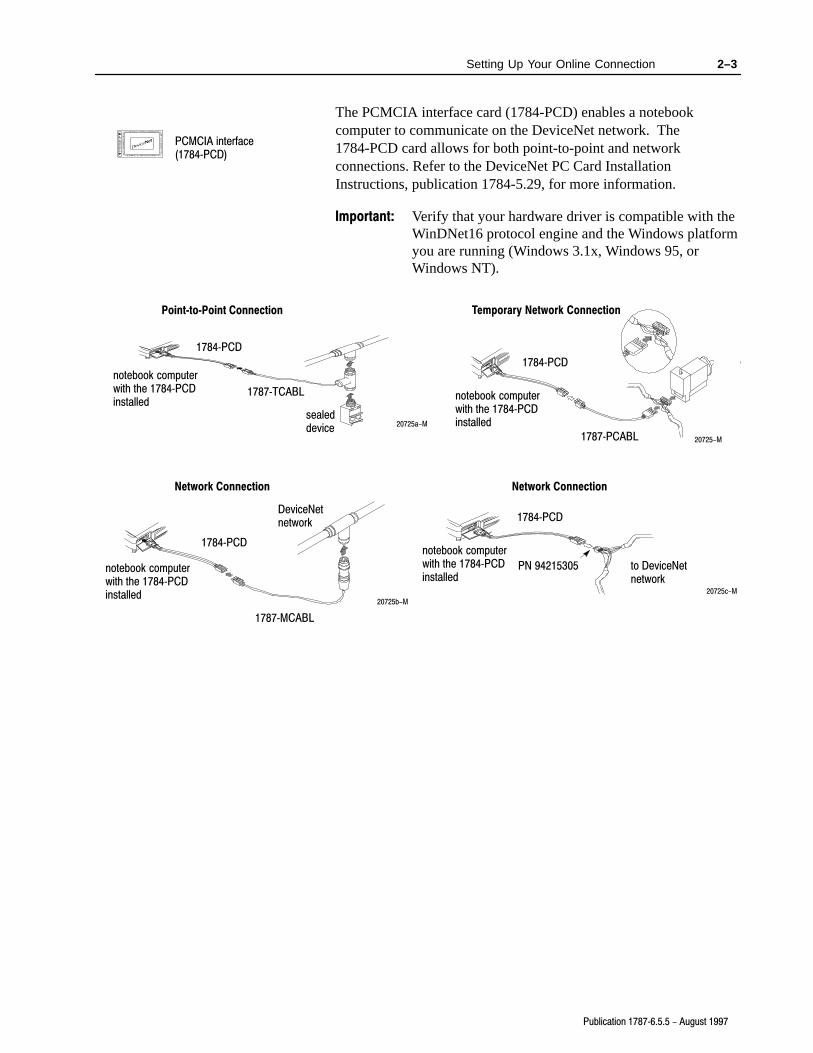
The PCMCIA interface card (1784-PCD) enables a notebookcomputer to communicate on the DeviceNet network. The1784-PCD card allows for both point-to-point and networkconnections. Refer to the DeviceNet PC Card InstallationInstructions, publication 1784-5.29, for more information.
Important: Verify that your hardware driver is compatible with theWinDNet16 protocol engine and the Windows platformyou are running (Windows 3.1x, Windows 95, orWindows NT).
20725a-M
20725b-M
notebook computerwith the 1784�PCDinstalled
1784�PCD
1787�TCABL
sealeddevice
notebook computerwith the 1784�PCDinstalled
1784�PCD
1787�MCABL
DeviceNetnetwork
notebook computerwith the 1784�PCDinstalled
1784�PCD
1787�PCABL
20725c-M
1784�PCD
to DeviceNetnetwork
PN 94215305
notebook computerwith the 1784�PCDinstalled
Point�to�Point Connection
Network Connection Network Connection
20725-M
Temporary Network Connection
PCMCIA interface(1784�PCD)

2–4 Setting Up Your Online Connection
Publication 1787�6.5.5 - August 1997
Follow the appropriate directions to power your RS-232 interfacemodule from the network or a 9V dc power-supply adapter.
Power From Network
1. Set the power switch to 1.
9�pin D�shellRS�232 connector
powerswitch
2. Insert the 9-pin D-shell RS-232 connector into the bottom of theRS-232 interface module.
3. Insert the other 9-pin D-shell RS-232 connector into a serial portof your computer.
4. Insert the network’s 5-pin unsealed connector into the top of theRS-232 interface module. This connects the RS-232 interfacemodule onto the trunk line enabling communication betweendevices on the network.
If the Module Status Indicator is Then
Blinking green You have connected properly
Not blinking green See the DeviceNet RS�232 Interface Module
Installation Instructions, publication 1770�5.6
Connecting theRS�232 Interface Module

2–5Setting Up Your Online Connection
Publication 1787�6.5.5 - August 1997
Power From 9V DC Power�Supply Adapter
1. Insert the power-supply connector into the appropriate port.
9�pin D�shellRS�232 connector
power supplyconnector
Adapter type Plug your adapter into a
U.S. 9V dc power�supply adapter 120V ac wall outlet
Global 9V dc power�supply adapter 90 to 260V ac wall outlet
If the Module Status Indicator is Then
Blinking green You have connected properly
Not blinking green See the DeviceNet RS�232 Interface Module
Installation Instructions, publication 1770�5.6
2. Insert the 9-pin D-shell RS-232 connector into the bottom of theRS-232 interface module.
3. Insert the other 9-pin D-shell RS-232 connector into a serial portof your computer.
4. Insert the network’s 5-pin unsealed connector into the top of theRS-232 interface module. This connects the RS-232 interfacemodule onto the trunk line enabling communication betweendevices on the network.

Chapter 3
Publication 1787�6.5.5 - August 1997
Going Online
Read this chapter to bring your DeviceNet network online.
For information on See page
Going online 3-1
Operating online 3-4
Going offline 3-4
Follow these directions to go online.
1. From the start-up menu, click on the DeviceNet Utilities 2.001icon.
You see this screen.
2. From the pull-down menu, choose your driver.
You can go online by choosing either the 1770-KFD RS-232Interface V1.50 driver, the 1784-PCD PCMCIA Interface driveror any other WinDNet16 interface card.
What's in This Chapter
Going Online

3–2 Going Online
Publication 1787�6.5.5 - August 1997
If you choose the 1784-PCD PCMCIA interface driver, you willsee this screen.
3. Choose
You see this screen.
The software automatically entersyour last used node address anddata rate for the driver.
!ATTENTION: Make sure that you are goingonline at the proper data rate. Attempting to goonline at the wrong data rate may cause some or alldevices on the network to fault.
4. Choose to go online.

3–3Going Online
Publication 1787�6.5.5 - August 1997
If you choose to go online using the 1770-KFD RS-232 interfaceV1.50 driver, you will see this screen.
5. Choose
You see this screen.
The software automatically entersyour last used node address anddata rate for the driver.
!ATTENTION: Make sure that you are goingonline at the proper data rate. Attempting to goonline at the wrong data rate may cause some or alldevices on the network to fault.
6. Choose to go online

3–4 Going Online
Publication 1787�6.5.5 - August 1997
Once you are online, the status bar indicates Ready and Online.
status bar
If you are using a 1770-KFD interface module, make sure that theNetwork Status Indicator is blinking green and the Module StatusIndicator is solid green.
Module Status Indicator
Network Status Indicator
Once you’ve finished your online operations, you may go offline.
From the Network menu, choose Disconnect.
Network
Operating Online
Going Offline

Chapter 4
Publication 1787�6.5.5 - August 1997
Using the Non�VolatileStorage Update Tool
Read this chapter to update the non-volatile memory ofAllen-Bradley DeviceNet devices.
For information on See page
About the NVS update tool 4-1
Initializing and Updating a device 4-2
The Non-Volatile Storage (NVS) Update tool provides a way forAllen-Bradley technical support personnel to update the firmwarecontained in a DeviceNet module from the network connection. You should only use the NVS Update tool if you intend to replacefirmware contained in a module with firmware provided by thedevice’s manufacturer.
The NVS Update tool copies device-specific firmware from thedevice manufacturer, which is normally supplied on an update disk,into a device’s non-volatile memory. This operation replaces thedevice’s previous firmware content. The NVS update disk does notallow you to copy the firmware from a device’s non-volatile memoryto any external form of recording media.
!ATTENTION: The NVS Update tool should not beused on any device which is currently involved withcontrolling the operation of a system. Any devicewhich is undergoing an NVS update must be removedfrom the control system prior to starting theNVS update.
What's in This Chapter
About the NVSUpdate Tool
4–2 Using the Non-Volatile Storage Update Tool
Publication 1787�6.5.5 - August 1997
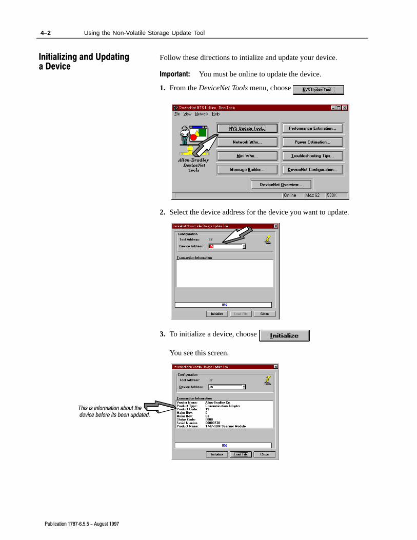
Follow these directions to intialize and update your device.
Important: You must be online to update the device.
1. From the DeviceNet Tools menu, choose
2. Select the device address for the device you want to update.
3. To initialize a device, choose
You see this screen.
This is information about the device before its been updated.
Initializing and Updating a Device

4–3Using the Non-Volatile Storage Update Tool
Publication 1787�6.5.5 - August 1997
4. Insert the device-specific firmware from the device manufacturerinto the 3.5” disk drive.
5. Choose
You see this screen.
6. Choose the (*.ini) file extension for the device you want toupdate.
7. Choose
You see this screen.
There are three screens similar to this screen.

4–4 Using the Non-Volatile Storage Update Tool
Publication 1787�6.5.5 - August 1997
8. Choose
You see this screen.
9. Choose
You see this screen.
10.Choose
You see this screen.
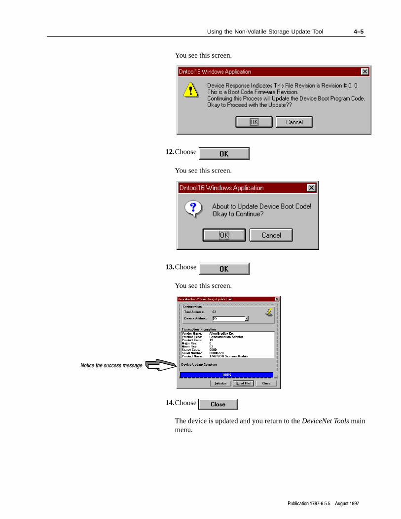
11.Choose
4–5Using the Non-Volatile Storage Update Tool
Publication 1787�6.5.5 - August 1997
You see this screen.
12.Choose
You see this screen.
13.Choose
You see this screen.
Notice the success message.
14.Choose
The device is updated and you return to the DeviceNet Tools mainmenu.

Chapter 5
Publication 1787�6.5.5 - August 1997
Using Network Whoand Mini Who
Read this chapter to use Network Who and Mini Who.
For information on See page
Using Network Who 5-1
Using Mini Who 5-3
The Network Who application provides a description of all deviceson your network. You should use the Network Who whenever youneed to obtain a detailed description of the devices on your activenetwork.
The Network Who communicates with each device on your networkto provide you with a description of each device. The informationpresented by the Network Who is retrieved from each device’sIdentity Object.
The Identity Object is present in all DeviceNet-compatible devicesand contains the following information:
• Vendor Identification
• Device Type
• Device Code
• Revision
• Status Code
• Serial Number
• Name String
The Network Who is usually capable of associating the numericalcodes returned from a device into text strings to present to you in theNetwork Who display. For example, a vendor-code value of 1corresponds to “Allen-Bradley Company”.
In cases where the Network Who cannot associate a code with a textstring it will substitute a generic text string such as “Unknownvendor ##”. The only exception to this generic substitutionconvention is the name-string field.
What's in This Chapter
Using Network Who

5–2 Using Network Who and Mini Who
Publication 1787�6.5.5 - August 1997
The name-string field is already in text format when it’s retrievedfrom the device. The Network Who presents the name string exactlyas it is presented by the device in the product-name column of theNetwork Who. Some devices have a blank name string and thereforea blank is placed in the product-name column for these devices.
Important: You must be online to select Network Who.
From the DeviceNet Tools menu, choose
You see this screen.

5–3Using Network Who and Mini Who
Publication 1787�6.5.5 - August 1997
To Choose
Return to the main menu
after compilation is completeX
Find out more information
about the devices
You see a screen similar to this one.
To scroll through the Network Who list,choose to move forward
or to move backward
Stop the compilation
of devices
List the devices after the
compilation is stopped
The Mini Who application provides you with a list of the activenodes on your network. You should use the Mini Who wheneveryou need to quickly obtain a list of the active node addresses on youractive network.
You must be online and connected to your network to perform a MiniWho. The Mini Who communicates briefly with each device onyour network to provide you with an indication of each device’spresence on the network.
The Mini Who is much faster than the Network Who but provides farless information about the networked devices.
Using Mini Who

5–4 Using Network Who and Mini Who
Publication 1787�6.5.5 - August 1997
Important: You must be online to select Mini Who.
From the DeviceNet Tools menu, choose
You see this screen.
To Choose
Return to the main menu after compilation
is complete
Stop the compilation of devices
Rescan the network for devices after the
compilation is stopped

Chapter 6
Publication 1787�6.5.5 - August 1997
Using the MessageBuilder & Monitor
Read this chapter to use the Message Builder & Monitor.
For information on See page
About the Message Builder & Monitor 6-1
Using the Message Builder & Monitor 6-2
The Message Builder & Monitor application allows you to send anddisplay explicit DeviceNet messages on a network. You must bethoroughly familiar with the DeviceNet communication protocol,including the data and service codes, to effectively utilize theMessage Builder & Monitor application.
You may use the Message Builder & Monitor to assist you in thetroubleshooting of a DeviceNet network or a specific device.For example, you may use the Message Builder & Monitor to sendan “open” request to a particular device and observe the response andpossibly the error codes resulting from your request.
The monitor portion of the Message Builder & Monitor allows youto view each communication packet transmitted and received by theDeviceNet Utilities communication software.
If you are using a communication adapter which filters out packetsnot directed at your own node address, as is the case for the1770-KFD interface module, you will only observe received packetswhich pass through your communication adapter’s filter.
What's in This Chapter
About the MessageBuilder & Monitor

6–2 Using the Message Builder & Monitor
Publication 1787�6.5.5 - August 1997
The Message Builder & Monitor provides low-level access to thecommunication services within the software and is not required fornormal system operation.
Follow these directions to use the Message Builder & Monitor.
1. From the DeviceNet Tools menu, choose
You see this screen.
2. In the message field, click on the appropriate radio button for thetype of message you want to see.
In this field Enter this information
Dest Node Destination node address for the send message function
Class Class to be used by the send message function
Inst Instance to be used by the send message function
Attr Attribute to be used by the send message function
3.
Using the MessageBuilder & Monitor

6–3Using the Message Builder & Monitor
Publication 1787�6.5.5 - August 1997
If you want to Choose
Clear the monitor display
Send a single DeviceNet message
Close this screen and return to theprevious screen
The monitor is updated with the message type you specified once
you choose
You see this screen.
4.

Chapter 7
Publication 1787�6.5.5 - August 1997
Loading the GTS Utilities Tools
Read this chapter to use the Performance Estimation Tool.
For information on See page
About the performance estimation tool 7-1
Loading the performance estimation tool 7-1
About the power estimation tool 7-2
Loading the power estimation tool 7-3
The Performance Estimation Tool is a Microsoft Excel spreadsheetthat estimates the performance of certain DeviceNet networks underspecific conditions. The Performance Estimation Tool is intendedfor use by Allen-Bradley technical support personnel and is builtaround the performance profile of the A-B SDN scanner modules.
You can use the Performance Estimation Tool to provide an estimateof the performance of your network if your network is similar to thenetwork modeled by the tool.
Follow these directions to estimate your device’s performance.
1. From the DeviceNet Tools menu, choose
What's in This Chapter
About the PerformanceEstimation Tool
Loading the PerformanceEstimation Tool

7–2 Loading the GTS Utilities Tools
Publication 1787�6.5.5 - August 1997
You see this screen.
The first time you load the Performance Estimation Tool, youmust specify the path to Microsoft Excel software.
2. Click once on the file name.
3. Choose
You see this screen.
The Power Estimation Tool is a Microsoft Excel spreadsheet thatestimates the power-supply requirements of your DeviceNetnetwork. The Power Estimation Tool is intended for use byAllen-Bradley technical support personnel and is built aroundstandard electrical power-distribution models and the power-supplyrequirements outlined in the DeviceNet Specification.
About the PowerEstimation Tool

7–3Loading the GTS Utilities Tools
Publication 1787�6.5.5 - August 1997
Follow these directions to estimate your device’s power.
1. From the DeviceNet Tools menu, choose
You see this screen.
The first time you load the Power Estimation Tool, you mustspecify the path to Microsoft Excel software.
2. Click once on the file name.
3. Choose
Loading the PowerEstimation Tool

7–4 Loading the GTS Utilities Tools
Publication 1787�6.5.5 - August 1997
You see this screen.

Chapter 8
Publication 1787�6.5.5 - August 1997
Help with TroubleshootingTips and DeviceNet Overview
Read this chapter to find out how to use the troubleshooting tips.
For information on See page
About the troubleshooting tips 8-1
Loading the troubleshooting tips 8-1
About the DeviceNet overview 8-2
Loading the DeviceNet overview 8-3
The Troubleshooting Tips are a compilation of hints and tips forsetting up and debugging a DeviceNet network in a Microsoft Worddocument. The number and nature of the tips provided will varyover time and will depend upon the submission of additional tipsfrom Allen-Bradley technical support personnel in the field.You may add your own tips to this document.
Follow these directions to use the troubleshooting tips.
1. From the DeviceNet Tools menu, choose
What's in This Chapter
About theTroubleshooting Tips
Loading theTroubleshooting Tips

8–2 Help with Troubleshooting Tips and DeviceNet Overview
Publication 1787�6.5.5 - August 1997
You see this screen.
The first time you load the troubleshooting tips tool, you mustspecify the path to Microsoft Word software.
2. Click once on the file name.
3. Choose
You see this screen.
The DeviceNet Overview is a Microsoft PowerPoint presentationcontaining a general overview of DeviceNet technology. You mayuse the DeviceNet Overview to familiarize yourself with theDeviceNet network.
About theDeviceNet Overview

8–3Help with Troubleshooting Tips and DeviceNet Overview
Publication 1787�6.5.5 - August 1997
Follow these directions to use the DeviceNet Overview function.
1. From the DeviceNet Tools menu, choose
You see this screen.
The first time you load the DeviceNet Overview tool, you mustspecify the path to Microsoft PowerPoint software.
2. Click once on the file name.
3. Choose
You see this screen.
Loading theDeviceNet Overview

Chapter 9
Publication 1787�6.5.5 - August 1997
Using the DeviceNet SystemConfigurator Software
Read this chapter to use the DeviceNet System Configurator(DSC) software.
For information on See page
About the DSC software 9-1
Running the DSC software 9-1
Allen-Bradley’s DSC software assists system designers in thelayout of the DeviceNet network. DSC software requires MicrosoftExcel, version 5.0. Online context-sensitive help aids in the layoutof your DeviceNet network.
DSC software has the following capabilities:
• provides a user interface to guide you in installing yournetwork properly
• enforces network specifications
• facilitates proper cable connections
• identifies components by description and catalog number
• generates a bill of materials (BOM) automatically
• generates network speed and network requirements automatically
Follow these directions to run the DSC software.
1. From the DeviceNet Tools menu, choose
What's in This Chapter
About the DSC Software
Running the DSC Software

9–2 Using the DeviceNet System Configurator Software
Publication 1787�6.5.5 - August 1997
You see this screen.
The first time you load the DSC software you must specify thepath to Microsoft Excel software.
2. Click once on the file name.
3. Choose
You see this screen.
4. Choose

9–3Using the DeviceNet System Configurator Software
Publication 1787�6.5.5 - August 1997
5. Next to Connection Type, choose the connection from thepull-down menu.
6. In the Trunk Line Media field, choose the resistor from thepull-down menu.
The part number isautomatically entered.
7. Choose
9–4 Using the DeviceNet System Configurator Software
Publication 1787�6.5.5 - August 1997
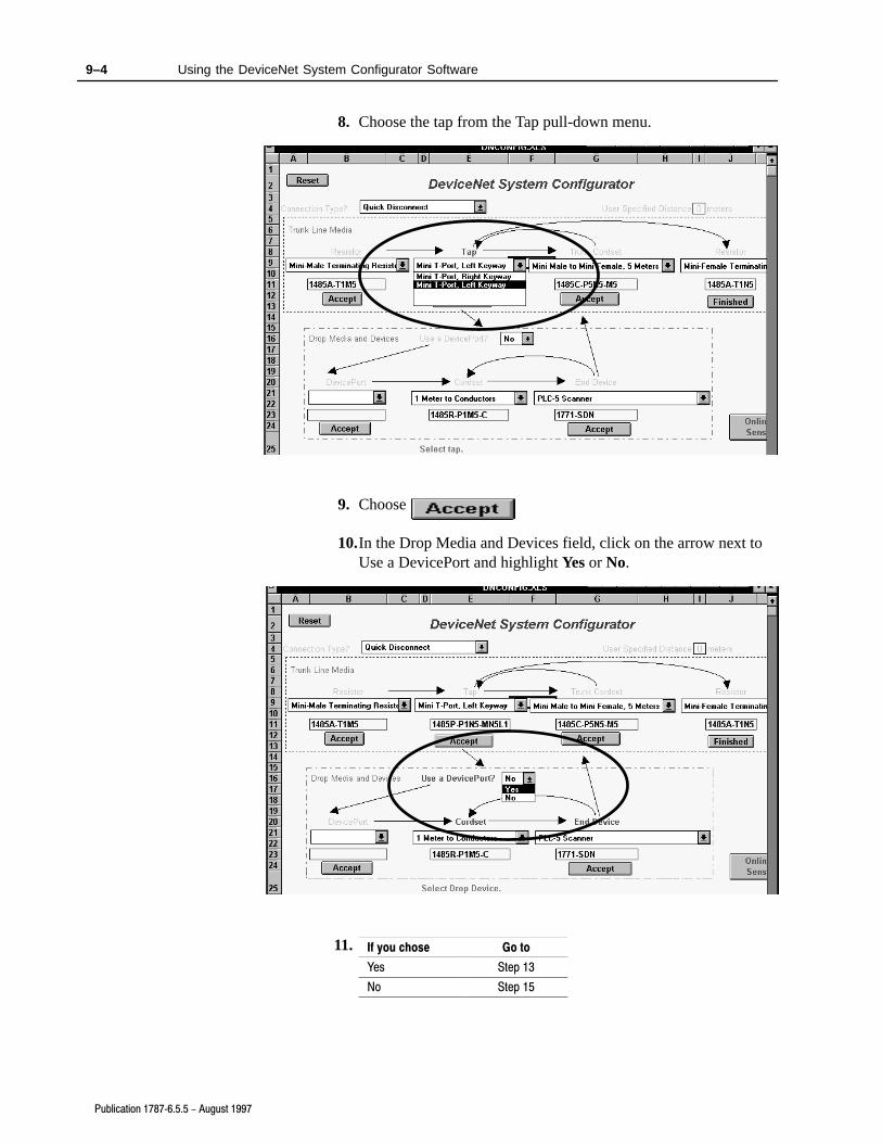
8. Choose the tap from the Tap pull-down menu.
9. Choose
10.In the Drop Media and Devices field, click on the arrow next toUse a DevicePort and highlight Yes or No.
If you chose Go to
Yes Step 13
No Step 15
11.

9–5Using the DeviceNet System Configurator Software
Publication 1787�6.5.5 - August 1997
12.Choose the DevicePort tap from the DevicePort pull-down menu.
13.Choose
14.Choos the cordset from the Cordset pull-down menu.
15.Choose

9–6 Using the DeviceNet System Configurator Software
Publication 1787�6.5.5 - August 1997
16.Choose the end device from the End Device pull-down menu.
17.Choose
18.In the Trunk Line Media field, choose the trunk cordset form theTrunk Cordset pull-down menu.
19.Choose

9–7Using the DeviceNet System Configurator Software
Publication 1787�6.5.5 - August 1997
20.Choose the resistor from the Resistor pull-down menu.
21.Choose
You see this screen as the bill of materials (BOM) is generatedand automatically printed.
Once printing is completed you return to the DeviceNet SystemConfigurator screen where you may layout another DeviceNetnetwork or exit Microsoft Excel.

Symbols
**Empty**, -1
A
audience, manual, P-1
B
barsmenu, P-2status, P-2tool, P-2
C
communication, DeviceNet, 2-1
configuration, online or offline, 3-1
connectionsnetwork, 2-3online, setting up, 2-3, 3-1point�to�point, 2-3RS�232 interface module, 2-4RS�232 module, 2-4
contents, manual, P-1
conventions, manual, P-1
D
deleting. See removing
DeviceNet, communication, 2-1
DeviceNet overviewabout, 8-2loading, 8-3
DeviceNet system configurator software.See DSC software
diagrams, DeviceNet communication, 2-1
DSC softwareabout, 9-1running, 9-1
I
indicators, interface module, 3-4
installingexiting, 1-7software, 1-2
interface moduleconnecting, 2-4indicators, 3-4power
from 9V dc power�supply adapter, 2-5
from network, 2-4
L
loadingDeviceNet overview, 8-3performance estimation tool, 7-1power estimation tool, 7-3troubleshooting tips, 8-1
M
manualaudience, P-1contents, P-1conventions, P-1
menu bar, P-2
message builder & monitor, 6-2about, 6-1
Mini Who, using, 5-3
N
networkconnection, 2-3power, 2-4
Network Who, using, 5-1
nvs tool, about, 4-1
O
offline, going, 3-4
onlineconnection, setting up, 2-3, 3-1operation, 3-4
P
performance estimation toolabout, 7-1loading, 7-1
point�to�point, connection, 2-3
Index

IndexI–2
power9V dc power�supply adapter, 2-3interface module
from 9V dc power�supply adapter, 2-5
from network, 2-4RS�232 module, 2-3
power estimation toolabout, 7-2loading, 7-3
power�supply adapter, 9V dc, power, 2-5
R
removing, software from hard drive, 1-7
requirements, system, 1-1
RS�232. See interface module
RS�232 moduleconnection, 2-4power, 2-3
S
screens, P-2menu and tool bars, P-2
softwareinstalling, 1-2removing from hard drive, 1-7
status bar, P-2
system requirements, 1-1
T
tool bar, P-2
troubleshooting tipsabout, 8-1loading, 8-1
W
WhoMini, using, 5-3Network, using, 5-1

9–10
Publication 1787�6.5.5 - August 1997
Pub. Name
Cat. No. Pub. No. Pub. Date Part No.
Check Problem(s) Type: Describe Problem(s): Internal Use Only
procedure/step
example
explanation
illustration
guideline
other
definition
feature
info in manual
(accessibility)
info notinmanual
text illustrationTechnical Accuracy
Completeness
What information is missing?
Clarity
Sequence
What is not in the right order?
What is unclear?
Other Comments
Use back for more comments.
Your Name Location/Phone
Return to: Marketing Communications, Allen-Bradley Co., 1 Allen-Bradley Drive, Mayfield Hts., OH 44124-6118Phone: (216)646-3176
FAX: (216)646-4320Publication ICCG�5.21�August 1995 PN 955107�82
DeviceNet GTS Utilities Software User Manual
1787�6.5.59240�GTSTK August 1997 955124�96

9–12
Publication 1787�6.5.5 - August 1997
Other Comments
PLEASE FOLD HERE
NO POSTAGE NECESSARY
IF MAILED IN THE
UNITED STATES
BUSINESS REPLY MAILFIRST-CLASS MAIL PERMIT NO. 18235 CLEVELAND OH
POSTAGE WILL BE PAID BY THE ADDRESSEE
1 ALLEN BRADLEY DRMAYFIELD HEIGHTS OH 44124-9705
PLE
AS
E R
EM
OV
E
PLEASE FASTEN HERE (DO NOT STAPLE)

9–2
Publication 1787�6.5.5 - August 1997
Allen�Bradley, a Rockwell Automation Business, has been helping its customers improveproductivity and quality for more than 90 years. We design, manufacture and support a broadrange of automation products worldwide. They include logic processors, power and motioncontrol devices, operator interfaces, sensors and a variety of software. Rockwell is one of theworld's leading technology companies.
Worldwide representation.
Argentina • Australia • Austria • Bahrain • Belgium • Brazil • Bulgaria • Canada • Chile • China, PRC • Colombia • Costa Rica • Croatia • Cyprus • Czech Republic •Denmark • Ecuador • Egypt • El Salvador • Finland • France • Germany • Greece • Guatemala • Honduras • Hong Kong • Hungary • Iceland • India • Indonesia •
Ireland • Israel • Italy • Jamaica • Japan • Jordan • Korea • Kuwait • Lebanon • Malaysia • Mexico • Netherlands • New Zealand • Norway • Pakistan • Peru •Philippines • Poland • Portugal • Puerto Rico • Qatar • Romania • Russia-CIS • Saudi Arabia • Singapore • Slovakia • Slovenia • South Africa, Republic • Spain •Sweden • Switzerland • Taiwan • Thailand • Turkey • United Arab Emirates • United Kingdom • United States • Uruguay • Venezuela • Yugoslavia
Allen�Bradley Headquarters, 1201 South Second Street, Milwaukee, WI 53204 USA, Tel: (1) 414 382�2000 Fax: (1) 414 382�4444
Publication 1787�6.5.5 - August 1997 PN 955124�96Copyright 1997 Allen�Bradley Company, Inc. Printed in USA