Embed Size (px)
Citation preview

QSFP-DD Modules MCB HCB Loopback Module Breakout Module
8x50G
ML4062-MCB ML4062-HCB1
ML4062-SLB-V1
ML4062-BO ML4062-MCB-MXP ML4062-SLB-V4
ML4062-MCB-LB ML4062-HCB2
ML4062-SLB-V6
ML4062-MCB-TR ML4062-XLB1
8x112G ML4062-MCB-112-24
ML4062-HCB-112-24 (set of 2)
ML4062-LB-112
ML4062-MCB-112-18 ML4062-HCB-112-18
(set of 2)
QSFP-DD Related Products Thermal Load Controller Adapter Analyzer
8x50G
ML4062-TL ML4062-CNT ML4066-QDD
ML4066-QDD-ANA ML4054-QDD
Loopback Module
ML4062-TL2a-C-LCD
ML4062-TL2a-C-LED
ML4062-TL2a-C-CON
The MultiLane QSFP-DD Development Kit provides the necessary development tools and reference
modules required for the development of QSFP-DD based products. This kit is essential for development,
testing and characterization of QSFP-DD based products. It can also be used for testing 400G CDRs, 400G
Gearbox devices, 400G QSFP-DD ports on routers and line-cards, electro-optical modules, and QSFP-DD
active optical cables.
TEST DEVELOPMENT KIT
QSFP-DD Development Platform Preliminary Specs

QSFP-DD QSFP-DD Module Compliance Board
ML4062-MCB
Key Features
• Supports 8x50G interfaces • I2C master driven from both on board
microcontroller or external pin headers • 40 GHz 2.92 mm K Connectors • Current Sense • Matched differential trace length • All 8 channels come with matching trace
length • High performance signal integrity traces from
K connectors to QSFP-DD host connector. • On-board LEDs display MSA output alarm
states • On-board buttons/jumpers for MSA input
control signals • User friendly GUI for I2C R/W commands and
loading custom MSA memory maps • Four corner testing capability • USB interface
Figure 2: ML4062-MCB
QSFP-DD Module Compliance Board
ML4062-MCB-MXP Key Features
• Supports 8x50G interfaces • I2C master driven from both on board
microcontroller or external pin headers • 2x8 Huber+Suhner MXP Connector rows • Current Sense • Internal noise injection option through a
programmable switching regulator • Power can be fed through an external source • Power margining between 3.1 V and 3.6 V • Matched differential trace length • All 8 channels come with matching trace
length • High performance signal integrity traces from
MXP connectors to QSFP-DD host connector. • On-board LEDs display MSA output alarm
states • On-board buttons/jumpers for MSA input
control signals
• User friendly GUI for I2C R/W commands and loading custom MSA memory maps
• Four corner testing capability • USB interface
Figure 4: ML4062-MCB-MXP
Figure 1: ML4062-MCB Insertion Loss
Figure 3: ML4062-MCB-MXP Insertion Loss
QSFP-DD Module Compliance Board (Host Loopback)
ML4062-MCB-LB
Key Features
• Supports 8x50G interfaces • I2C master driven from both on board
microcontroller or external pin headers • Current Sense • Internal noise injection option through a
programmable switching regulator • All TX channels are looped back to the RX side
on host with ≈ 1 dB loss • Power can be fed through an external source • Power margining between 3.1 V and 3.6 V • On-board LEDs display MSA output alarm
states • On-board buttons/jumpers for MSA input
control signal • User friendly GUI for I2C R/W commands and
loading custom MSA memory maps • Four corner testing capability • USB interface
Figure 5: ML4062-MCB-LB
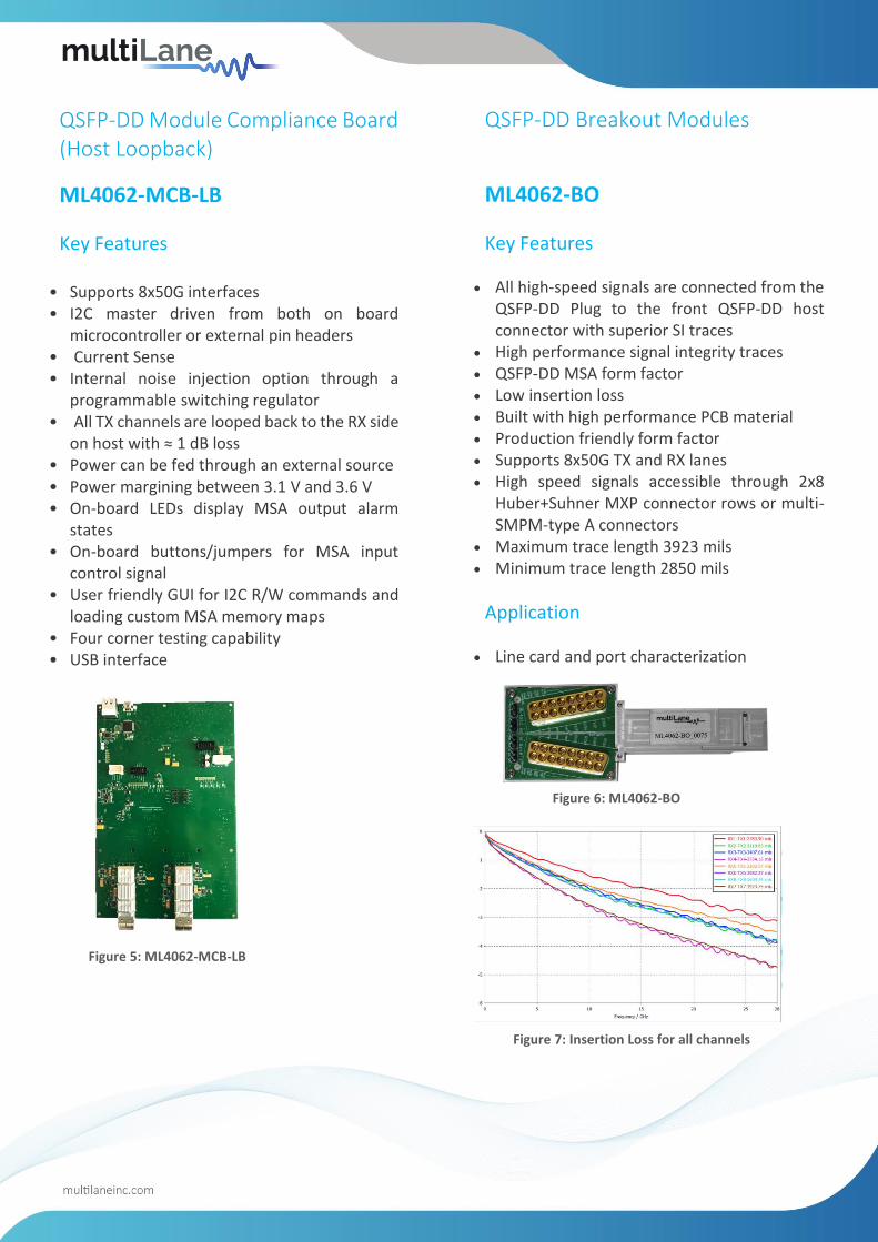
QSFP-DD Breakout Modules
ML4062-BO
Key Features
• All high-speed signals are connected from the QSFP-DD Plug to the front QSFP-DD host connector with superior SI traces
• High performance signal integrity traces • QSFP-DD MSA form factor • Low insertion loss • Built with high performance PCB material • Production friendly form factor • Supports 8x50G TX and RX lanes • High speed signals accessible through 2x8
Huber+Suhner MXP connector rows or multi-SMPM-type A connectors
• Maximum trace length 3923 mils • Minimum trace length 2850 mils
Application
• Line card and port characterization
Figure 6: ML4062-BO
Figure 7: Insertion Loss for all channels

QSFP-DD Host Compliance Board
ML4062-HCB1
Key Features • High Performance signal integrity traces • QSFP-DD MSA Form Factor • Same low Insertion Loss for all traces • Built with high performance PCB material • Production friendly form factor • Supports 4x50 G • 4 channels: Ch1, Ch2, Ch3, Ch4
CH1 CH2 CH3 CH4
TX1 RX1 TX2 RX2 TX3 RX3 TX4 RX4
• Built with high performance PCB material • High speed signals accessible through K
connector rows
Figure 8: ML4062-HCB1
CH5 CH6 CH7 CH8
TX5 RX5 TX6 RX6 TX7 RX7 TX8 RX8
• Built with high performance PCB material • High speed signals accessible through K
connector rows
Figure 9: ML4062-HCB2
QSFP-DD Host Compliance Board
ML4062-HCB2
Key Features • High Performance signal integrity traces • QSFP-DD MSA Form Factor • Same low Insertion Loss for all traces • Built with high performance PCB material • Production friendly form factor • Supports 4x50 G • 4 channels: Ch5, Ch6, Ch7, Ch8
QSFP-DD Module Compliance Board
ML4062-MCB-TR
Key Features
• Consumable, low-cost MCB for volume testing to be used in combination with a replaceable multi-channel cable
• I2C master driven from either on-board microcontroller or external pin headers
• Current sensor • Voltage sensor • Two temperature sensors • Matched differential trace length across all
channels • High performance signal integrity traces from
TR40 connectors to QSFP-DD host connector • On-board LEDs display MSA output alarm
states • On-board jumpers for MSA input control
signals • User friendly GUI for I2C R/W commands and
loading custom MSA memory maps • Four corner testing capability • USB interface • QSFP-DD analyzer interface for ML4066-ANA
I2C CMIS testing
Figure 10: ML4062-MCB-TR
• No components near QSFP-DD cage makes thermal testing easy to achieve
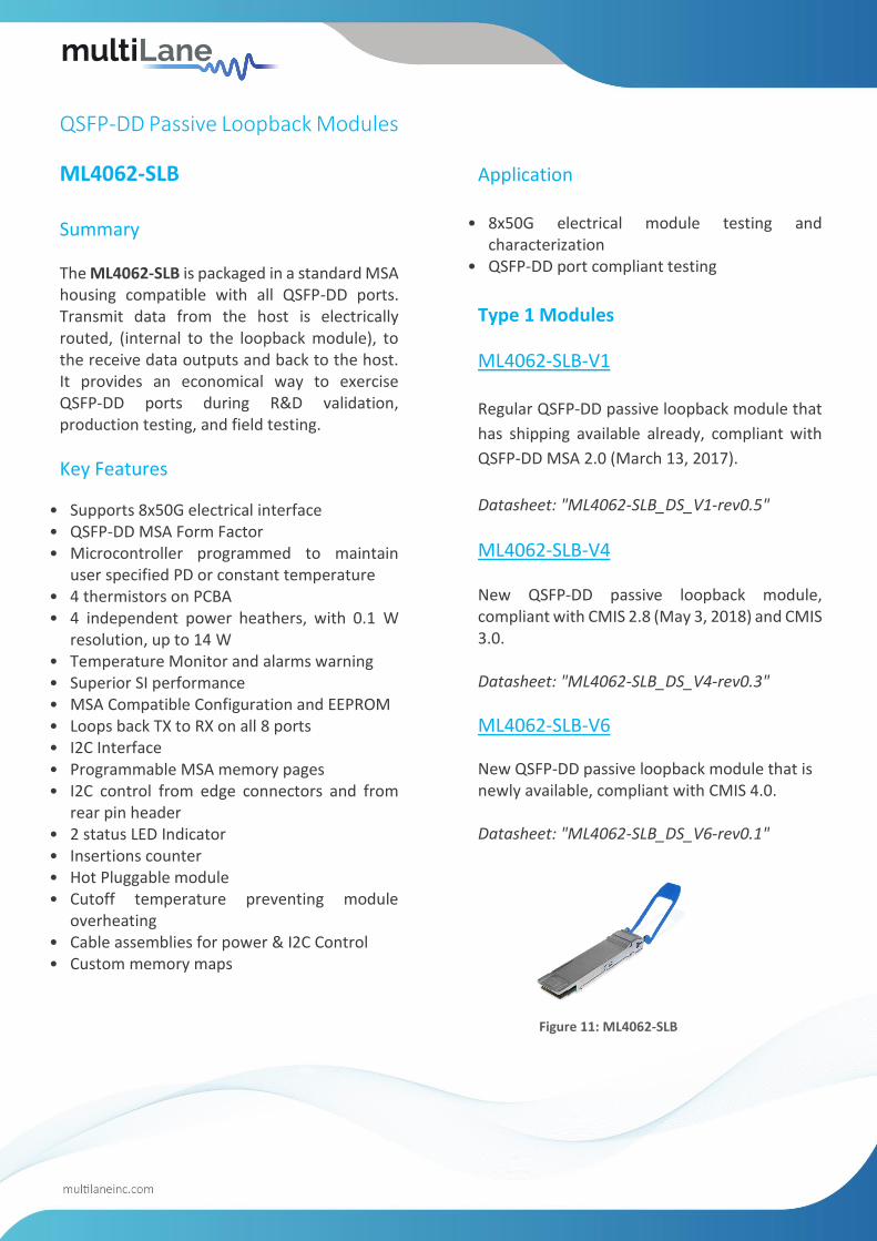
QSFP-DD Passive Loopback Modules
ML4062-SLB Summary
The ML4062-SLB is packaged in a standard MSA housing compatible with all QSFP-DD ports. Transmit data from the host is electrically routed, (internal to the loopback module), to the receive data outputs and back to the host. It provides an economical way to exercise QSFP-DD ports during R&D validation, production testing, and field testing.
Key Features
• Supports 8x50G electrical interface • QSFP-DD MSA Form Factor • Microcontroller programmed to maintain
user specified PD or constant temperature • 4 thermistors on PCBA • 4 independent power heathers, with 0.1 W
resolution, up to 14 W • Temperature Monitor and alarms warning • Superior SI performance • MSA Compatible Configuration and EEPROM • Loops back TX to RX on all 8 ports • I2C Interface • Programmable MSA memory pages • I2C control from edge connectors and from
rear pin header • 2 status LED Indicator • Insertions counter • Hot Pluggable module • Cutoff temperature preventing module
overheating • Cable assemblies for power & I2C Control • Custom memory maps
Application
• 8x50G electrical module testing and characterization
• QSFP-DD port compliant testing
Type 1 Modules
ML4062-SLB-V1
Regular QSFP-DD passive loopback module that
has shipping available already, compliant with
QSFP-DD MSA 2.0 (March 13, 2017).
Datasheet: "ML4062-SLB_DS_V1-rev0.5"
ML4062-SLB-V4
New QSFP-DD passive loopback module, compliant with CMIS 2.8 (May 3, 2018) and CMIS 3.0. Datasheet: "ML4062-SLB_DS_V4-rev0.3"
ML4062-SLB-V6
New QSFP-DD passive loopback module that is newly available, compliant with CMIS 4.0. Datasheet: "ML4062-SLB_DS_V6-rev0.1"
Figure 11: ML4062-SLB

QSFP-DD Thermal Load
ML4062-TL Key Features
• QSFP-DD MSA form factor • Microcontroller can be programmed to
maintain user specified PD or constant temperature
• 4 temperature sensors • 23 independent power spots • Temperature monitor and alarms warning • MSA compatible configuration and EEPROM • I2C interface • Programmable MSA memory pages • I2C control rom edge connectors and from
rear pin header • Hot pluggable module • Cut-off temperature preventing module
overheating • Controller card with I2C Master, supports
multiple modules, USB master • Cable assemblies for power & I2C control • Custom memory maps
QSFP-DD Controller
ML4062-CNT Key Features
• The controller is powered using a 24 V external power supply.
• Two thermal loads modes are available: constant temperature and constant power dissipation.
▪ Constant Temperature Option 1: Used to fix the total temperature of the module (Enter the temperature value and click Set)
Option 2: Used to fix the temperature of a specified spot in the module (Select the spot that you need to fix its temperature, enter the temperature value and click Set).
▪ Constant Power Dissipation Used to set the power value of the desired spot using the corresponding slider.
• The user can set the temperature cut-off value using the Cut-off temperature field.
• Module VCC can be set to 3.3 or 3.5 V. The temperature values can be logged. The Interval indicates the time spent between consecutive temperature measurements.
• The total duration indicates the total times of logging temperature values.
• After the logging is done, you can view the graph that shows the temperature in time.
Ordering Information
ML4062-CNT Regular controller
ML4062-CNT-Gen2 Reworked CNT that works with TL2a
ML4062-CNT-CBL Regular cable for TL1/TL2
ML4062-CNT-CBL-G2 Cable for TL2a
Figure 13: ML4062-CNT
Figure 12: ML4062-TL

400G QSFP-DD Passive Loopback Module
ML4062-XLB1
Key Features
• Crossed, Looped back TX to RX on all 8 ports • Supports 8x50G electrical interface • QSFP-DD MSA Form Factor • Built with advanced PCB material • 4 Thermistors on PCBA • 4 independent power heaters, up to 14W • Temperature Monitor and alarms warning • Superior SI performance • MSA Compatible Configuration and EEPROM • I2C Interface • Programmable MSA memory pages • 2 status LED Indicators • Insertions counter • Hot Pluggable module • Cut-off temperature preventing module
overheating
Figure 14: ML4062-XLB1

Ordering Options
Option Part Number Description
#1 – LCD Display ML4062-TL2a-C-LCD Temperature and other monitoring values
#2 – LED Indicator ML4062-TL2a-C-LED Power mode and alarms monitoring
#3 – Pin Header ML4062-TL2a-C-CON Board to board connection
NEW RELEASES QSFP-DD Electrical Passive Loopback Module
ML4062-TL2a
Summary ML4062-TL2a is used for testing QSFP-DD transceiver ports under board level tests, by substituting a full-featured QSFP-DD transceiver with the ML4062-TL2a. The ML4062-TL2a covers all QSFP-DD power classes. The ML4062-TL2a is packaged in a standard MSA housing compatible with all QSFP-DD ports. It provides an economical way to exercise QSFP-DD ports during R&D validation, production testing, and field testing. Note that the ML4062-TL2a follows the CMIS Rev 4.0 standard.
Key Features
• QSFP-DD MSA Form Factor • MSA Compatible Configuration and EEPROM • Programmable MSA memory pages • Custom memory maps • I2C Interface • I2C control from edge connectors and from
rear pin header
• Controller card with I2C Master, supports multiple modules, USB master
• Hot Pluggable module • Ten independent power spots dissipating up
to 23.4 W • Four temperature sensors
• Voltage sensor • Current sensor
• Temperature Monitor and alarms warning • Cut-off temperature preventing module
overheating
#1 LCD Display #2 LED Indicator #3 Pin Header

NEW RELEASES 800G QSFP-DD MCB
ML4062-MCB-112 Key Features
• Supports 8x112G interfaces • Compliant with CEI-112G-VSR-PAM4 and CEI-
56G-VSR-NRZ • I2C master driven from both on board
microcontroller or external pin headers • 2.4 or 1.85mm connectors • Current Sense • Matched differential trace length • All 8 channels come with matching trace length • High performance signal integrity traces from
2.4 or 1.85mm connectors to QSFP-DD host connector.
• On-board LEDs display MSA output alarm states • Built with high performance PCB material • On-board buttons/jumpers for MSA input
control signals • User friendly GUI for I2C R/W commands and
loading custom MSA memory maps • Four corner testing capability
800G QSFP-DD HCB
ML4062-HCB1-112
Key Features
• High performance signal integrity traces
• Compliant with CEI-112G-VSR-PAM4 and CEI-56G-VSR-NRZ
• QSFP-DD MSA Form Factor • Same low Insertion Loss for all traces
• Supports 4x112G • Built with high performance PCB Material • High speed signals accessible through 2.4 or
1.85mm connectors • 4 channels: 4 TX and the corresponding 4 RX
CH1 CH2 CH3 CH4
TX1 RX1 TX2 RX2 TX3 RX3 TX4 RX4
Figure 15: ML4062-MCB-112
Figure 16: ML4062-HCB1-112

Figure 18: ML4062-LB-112
800G QSFP-DD HCB
ML4062-HCB2-112
Key Features
• High performance signal integrity traces
• Compliant with CEI-112G-VSR-PAM4 and CEI-56G-VSR-NRZ
• QSFP-DD MSA Form Factor • Same low Insertion Loss for all traces
• Supports 4x112G • Built with high performance PCB Material • High speed signals accessible through 2.4 or
1.85mm connectors • 4 channels: 4 TX and the corresponding 4 RX
CH5 CH6 CH7 CH8
TX5 RX5 TX6 RX6 TX7 RX7 TX8 RX8
Figure 17: ML4062-HCB2-112
800G QSFP-DD Loopback Module
ML4062-LB-112
Key Features
• Loops back TX & RX with good performance SI
Traces
• Built with advanced PCB Material
• MSA Compliant Shell with latching mechanism
• Four thermal spots
• Can emulate all QSFP-DD power classes
• Can dissipate up to 16 W via the thermal loads
• Temp sense
• I2C Terminated by microcontroller, I2C slave
compliant with MSA
• Implements MSA Memory Map with
programmable new pages
• Ability to control/monitor all low speed signals
• Insertion Counter
• Front LED Indicator
• Hot Pluggable
• Cut-off temperature preventing module
overheating
• AC-coupled High-Speed Interface

Host Side Module Side
1 VCC VCC
2 VCC-TX VCC-TX
3 VCC-RX VCC-RX
4 MODSEL_L MODSEL_L
5 RESET_L RESET_L
6 SCL SCL
7 SDA SDA
8 MODPRS_L MODPRS_L
9 INT_L INT_L
10 LPMODE LPMODE
11 GND GND
RELATED PRODUCT QSFP-DD to QSFP-DD Adapter
ML4066-QDD
Key Features
• All high-speed signals are connected from the QSFP-DD Plug to the front QSFP-DD host connector with superior SI traces
• Low insertion loss PCB traces • Power pins are accessible via pin headers and
can be jumped to connect them to the plugged QSFP-DD transceiver
• All low speed management signals are accessible via pin headers, and can be jumped to connect them to the plugged QSFP-DD transceiver
• I2C SCL and SDA signals accessible via pin headers or can be jumped to connect them to the plugged QSFP-DD transceiver
• Ability to drive I2C from external pin headers, or connect I2C packet analyzer
• Ability to drive 3.3 V from external source for power supply margining
• Ability to break 3.3 V power from Host to module allowing voltage and current measurement
• Signal interface to connect SFF Analyzer board • ML4066-QDD Pin headers
SFF Analyzer
ML4066-QDD-ANA
Key Features
• USB Interface • Windows based GUI and API Library • Detection and measurement of host pull up + pull
down resistors on low speed signals • Host VCC rails sampling measurement • VCC spectral noise analysis • I2C Analyzer
o Bus speed o ACK/NACK DETECTION o Clock stretching analysis o Time event logging
• Functional tests o Control signals o Configuration registers o Ability to emulate optical module by loading
identification registers with custom data o Built with advanced PCB Material o I2C terminated by microcontroller, I2C slave
compliant with MSA o Implements MSA memory map and
programmable new pages o Memory map can be loaded to replicate optical
module’s identification registers o Ability to control/monitor all low speed signals o Hot pluggable o AC coupled high speed interface o CMIS state machine testing
CMIS State Machine Analyzer
• Analyzer test available on all QSFP-DD modules that are CMIS 4.0 compliant
• Ability to test different state transitions • Paged memory map and flat memory map show
the module’s current state and transition signals
Figure 20: ML4066-QDD ADP/ANA

North America Worldwide Asia
48521 Warm Springs Boulevard Houmal Technology Park 14F-5/ Rm.5, 14F., No 295 Suite 310. Askarieh Main Road Sec.2, Guangfu Rd. East Dist., Fremont, CA 94539, USA Houmal, Lebanon Hsinchu City 300, Taiwan (R.O.C) +1 510 573 6388 +961 5 941 668 +886 3 5744 591
CFP8 to QSFP-DD Adapter
ML4054-QDD
• All high-speed signals are connected from the CFP8 Plug to the front QSFP-DD host connector with superior SI traces.
For more info, please find full datasheet here.
Figure 23: ML4054-QDD
Figure 21: Paged Memory Modules
Figure 22: Flat Memory Modules


![Tech Specsimage.promax.com/.../downloads/ProMAXPlatformOnlineTechSpecs.pdf · Tech Specs 2850 S. Fairview St. Santa Ana, CA 92704 (800) 977-6629 Platform [T1-16X] Platform [T1-16Y]](https://img.dokumen.tips/doc/110x75/5a71a03e7f8b9ab6538ce719/tech-specsimagepromaxcomdownloadspromaxplatformonlinetechspecspdfpdf.jpg)