Embed Size (px)
Citation preview
Development of Ultimate Seamless Positioning
System based on QZSS IMES
Dinesh Manandhar, Kazuyuki Okano, Makoto Ishii, Hideyuki Torimoto
GNSS Technologies Inc., Japan
Satoshi Kogure, Japan Aerospace Exploration Agency (JAXA), Japan
Hiroaki Maeda, Lighthouse Technology and Consulting, Japan
BIOGRAPHY
Dinesh Manandhar is a Senior Researcher at GNSS
Technologies Inc. He is also a visiting researcher at the
University of Tokyo. He received Ph. D. from the
University of Tokyo, Japan in 2001. Currently, he is
involved in indoor signal analysis. He is one of the
members to design and develop IMES.
Kazuki Okano is chief engineer at GNSS Technologies
Inc. He is involved in hardware design and development
for Pseudolites and IMES.
Makoto Ishii is Director of Strategic Marketing and Sales
of GNSS Technologies Inc. He is coordinating GNSS
based technologies in the business department including
IMES.
Hideyuki Torimoto is president of GNSS Technologies
Inc. He is one of the pioneers of satellite navigation
related application businesses in Japan. He established
Trimble Japan in 1986. In 2002, he founded GNSS
Technologies Inc. to promote R&D as well as marketing
in the field of GNSS in Japan. He is managing GNSS
R&D including IMES to promote the technology
internationally. He served as Satellite Division Member of
ION for 2003-04.
Satoshi Kogure is an associate senior engineer of JAXA.
He received MS in aerospace engineering from University
of Colorado in 2001. He has been working for satellite
positioning system as a satellite systems engineer since
2001. He is one of the members to design and develop
IMES.
Hiroaki Maeda is the founder and the managing director
of Lighthouse Technology and Consulting Co., Ltd
(LHTC). He received Ph. D from the Tokyo University of
Marine Science and Technology in 2008. Since 2003 he
has been a technical lead of the Japanese satellite
navigation system, QZSS. He is one of the members to
design and develop IMES.
ABSTRACT
Satellite-based navigation systems generate huge location
based service markets and it is expected that the market
will drastically increase in near future due to necessity of
GNSS enabled mobile phones for emergency services in
USA, Japan and many other countries. In order to realize
such huge growth, it is necessary to address the problems
of seamless navigation which are limited by the current
GNSS based applications alone. These systems are not
strong enough to provide navigation in indoor and deep
indoor environments with required resolutions. In order to
solve these problems and provide indoor position, we
have developed Indoor Messaging System (IMES).
The basic concept of the IMES is to transmit position data
and/or unique ID and/or other user defined data from the
transmitter while keeping the similar signal structure as of
QZSS/GPS signal. IMES has the same RF properties as
GPS/QZSS and PRN IDs from 173 to 182 are assigned
for IMES. The only difference is in the contents of
navigation message which can be set as per user’s
necessity and application fields. It is not necessary to
compute pseudorange, hence a single unit is enough for
position data.
We have developed prototype IMES device based on
QZSS-IS document. Experiments have been conducted
using software receiver and prototype IMES capable
mobile phone devices. The seamless navigation capability
has been demonstrated by using the IMES capable mobile
phone device. The mobile phone shows the user position
in seamless fashion when the user moves indoors and
outdoors. The interference analysis results showed that
with proper separation of other GNSS devices from IMES
transmitter, there is no harmful interference to the GNSS
user. Based on these experiments, minimum threshold
distance has been estimated, which is about 1.6m from the
IMES antenna at transmission power of -70dBm. This
paper discuss about IMES concept, signal structure,
prototype device, various experiments and their results.
INTRODUCTION
Localization or the problem of estimating spatial
relationships among objects has been a classical problem
in many disciplines. Positioning types range from
proximity indication, crossing of boundary, or precise
positioning. The requirement for positioning systems
depends on types of applications. However, positioning
alone does not help much unless the position data are
associated with other related database. The use is limited
if a user knows only his position. However, this limitation
can be expanded if the position data are related with local
database and ultimately to the global database. The rooms
in a building may have the same physical characteristics
but they are associated with different information. Thus
just knowing the building location is not enough for many
applications. The user always need to know it’s location,
direction and relation with other objects and database
regardless of whether the user is outdoors or indoors.
These are the key factors for seamless navigation.
Satellite-based navigation systems like GPS and
GLONASS work well outdoors but their use is limited
indoors due to poor visibility of satellites. In near future,
there will be GALILEO, QZSS and COMPASS for
satellite-based navigation systems. However, for good 3D
position estimation at least four visible satellites are
necessary. It’s almost impossible to compute a position
indoors using such satellite signals without any external
aiding of information. Though, there are weak signal
processing capable receivers, they do need information
about the satellite orbits and/or time which are normally
provided by some external means. There are also
positioning systems that are based on the combination of
GPS and cellular phone networks. However, they still do
lag in providing correct 3D information and need
infrastructure setup in the existing cellular networks
which are not always possible. In the case of emergency,
how do we know that whether the victim is in the 50th
Floor, room number 510 or room number 512? Or how do
we know that whether the victim is in the 5th Floor below
the basement in room number 110? The key point here is
to identify precisely the location of the victim without any
mistakes. We do not want to search and rescue the victim,
but we would like to locate and rescue the victim. This is
the fundamental difference between other GNSS based
systems and IMES.
There are many cases when accurate indoor location
information is necessary. In order to overcome these
problems a new signal has been defined in QZSS IS
document which is known as IMES (Indoor Messaging
System). IMES has been jointly developed by Japan
Aerospace Exploration Agency (JAXA), GNSS
Technologies Inc. and Light House Technology and
Consulting Co. Ltd. (LHTC).
The development includes hardware, software, signal
structure and message formats.
IMES CONCEPT
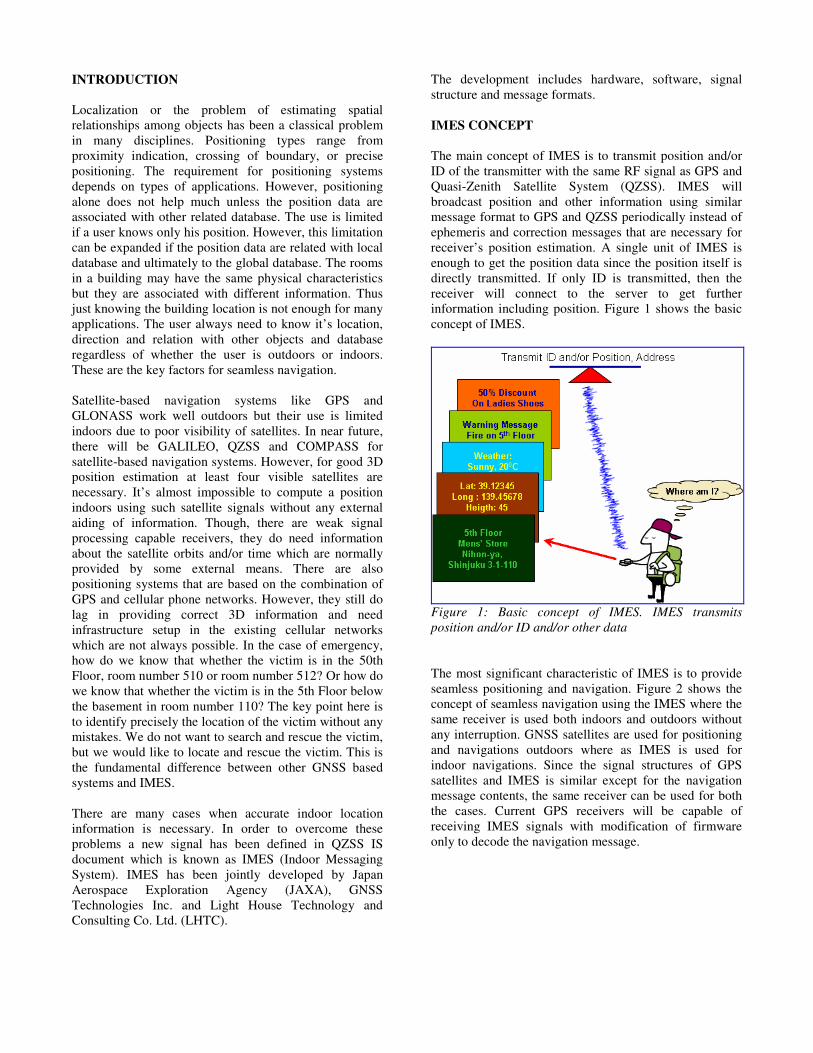
The main concept of IMES is to transmit position and/or
ID of the transmitter with the same RF signal as GPS and
Quasi-Zenith Satellite System (QZSS). IMES will
broadcast position and other information using similar
message format to GPS and QZSS periodically instead of
ephemeris and correction messages that are necessary for
receiver’s position estimation. A single unit of IMES is
enough to get the position data since the position itself is
directly transmitted. If only ID is transmitted, then the
receiver will connect to the server to get further
information including position. Figure 1 shows the basic
concept of IMES.
Figure 1: Basic concept of IMES. IMES transmits
position and/or ID and/or other data
The most significant characteristic of IMES is to provide
seamless positioning and navigation. Figure 2 shows the
concept of seamless navigation using the IMES where the
same receiver is used both indoors and outdoors without
any interruption. GNSS satellites are used for positioning
and navigations outdoors where as IMES is used for
indoor navigations. Since the signal structures of GPS
satellites and IMES is similar except for the navigation
message contents, the same receiver can be used for both
the cases. Current GPS receivers will be capable of
receiving IMES signals with modification of firmware
only to decode the navigation message.
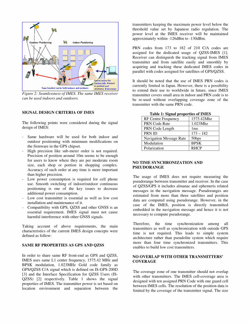
Figure 2: Seamlessness of IMES. The same IMES receiver
can be used indoors and outdoors.
SIGNAL DESIGN CRITERIA OF IMES
The following points were considered during the signal
design of IMES:
- Same hardware will be used for both indoor and
outdoor positioning with minimum modifications on
the firmware in the GPS chipset.
- High precision like sub-meter order is not required.
Precision of position around 10m seems to be enough
for users to know where they are per moderate room
size, each shop or portion in shopping complex.
Accuracy of such order at any time is more important
than higher precision.
- Low power consumption is required for cell phone
use. Smooth switching of indoor/outdoor continuous
positioning is one of the key issues to decrease
additional power consumption.
- Low cost transmitter is essential as well as low cost
installation and maintenance of it.
- Compatibility with GPS, QZSS and other GNSS is an
essential requirement. IMES signal must not cause
harmful interference with other GNSS signals.
Taking account of above requirements, the main
characteristics of the current IMES design concepts were
defined as follow:
SAME RF PROPERTIES AS GPS AND QZSS
In order to share same RF front-end as GPS and QZSS,
IMES uses same L1 center frequency, 1575.42 MHz and
BPSK modulation, 1.023MHz Gold code family as
GPS/QZSS C/A signal which is defined on IS-GPS-200D
[3] and the Interface Specification for QZSS Users (IS-
QZSS) [2] respectively. Table 1 shows the signal
properties of IMES. The transmitter power is set based on
location environment and separation between the
transmitters keeping the maximum power level below the
threshold value set by Japanese radio regulation. The
power level at the IMES receiver will be maintained
approximately within -126dBm to -130dBm.
PRN codes from 173 to 182 of 210 C/A codes are
assigned for the dedicated usage of QZSS-IMES [1].
Receiver can distinguish the tracking signal from IMES
transmitter and from satellite easily and smoothly by
acquiring and tracking these dedicated IMES codes in
parallel with codes assigned for satellites of GPS/QZSS.
It should be noted that the use of IMES PRN codes is
currently limited in Japan. However, there is a possibility
to extend their use to worldwide in future, since IMES
transmitter covers small area in indoor and PRN code is to
be re-used without overlapping coverage zone of the
transmitter with the same PRN code.
Table 1: Signal properties of IMES
RF Centre Frequency 1575.42Mhz
PRN Code Rate 1.023Mhz
PRN Code Length 1ms
PRN ID 173 – 182
Navigation Message Rate 50bps
Modulation BPSK
Polarization RHCP
NO TIME SYNCHRONIZATION AND
PSEUDORANGE
The usage of IMES does not require measuring the
pseudorange between transmitter and receiver. In the case
of QZSS/GPS it includes almanac and ephemeris related
messages in the navigation message. Pseudoranges are
estimated from more than three satellites and position
data are computed using pseudorange. However, in the
case of the IMES, position is directly transmitted
embedded in the navigation message and hence it is not
necessary to compute pseudorange.
Therefore, the time synchronization among all
transmitters as well as synchronization with outside GPS
time is not required. This leads to simple system
architecture rather than pseudolite system which require
more than four time synchronized transmitters. This
enables to build low cost transmitters.
NO OVERLAP WITH OTHER TRANSMITTERS’
COVERAGE
The coverage zone of one transmitter should not overlap
with other transmitters. The IMES cell-coverage area is
designed with ten assigned PRN Code with one guard cell
between IMES cells. The resolution of the position data is
limited by the coverage of the transmitter signal. The size

of each coverage zone is equivalent to maximum
positioning error. Usually, one coordinate for a moderate
sized room can be transmitted by one transmitter. Large
areas such as underground malls, metro stations, and
department stores, the transmitters may be distributed at
10-15m span.
RF COMPATIBILITY WITH OUTSIDE GNSS
SIGNALS
IMES signals are transmitted at low power to avoid
interference with live GNSS signals. In addition to this
low power transmission, the separation between
transmitters contributes to avoid increasing noise floor by
multiple IMES signals. Moreover, an appropriate
separation distance between an IMES transmitter and an
outside GNSS receiver should be maintained. The
separation distance is to be defined in the annex of IS-
QZSS as an installation standard. Results of interference
analysis are discussed in the later section of the paper.
MESSAGE STRUCTURE
The message structure of IMES is similar to QZSS or
GPS L1C/A and is defined in the annex of IS-QZSS. The
message consists of words of 30bits. Depending upon
message types, the number of words in a frame can vary.
Currently, there are four types of IMES messages defined
that are named as type “0”, “1”, “3”, and “4” as shown in
Figure 3 to Figure 6 respectively. Message type “0”
contains 2-D position data using three words of 30bits
each. This is the shortest message length to transmit
absolute position data using latitude, longitude and floor
data. Message type “1” contains 3-D position data using
four words of 30bits each and the resolution is as twice
fine as the position transmitted in message type “0”.
Since, floor number is considered more important than
height (for inside the building data), floor number is given
higher priority than height data in the current message
type design. Message type “3” and “4” contains only IDs
and are one and two words long respectively. The first of
each frame has an eight bit preamble followed by
message type. The corresponding words of a frame have
three bit counter at the beginning of each word. Since,
message type “3” has one word only, it does not have
counter bits. It takes 0.6 sec to read one word at 50bps.
Message type “3” and “4” do not contain any position
data or coordinates. The position data are retrieved from
database server based on the unique ID to get the latitude,
longitude, height, floor number as well as other value-
added information such as guidance map, advertising and
so on. Medium IDs are unique IDs assigned to each
operator, for instance, department store, underground mall
and etc. Medium ID works for connecting each IMES
transmitter to local server established by each operator to
provide LBS services to their customers. Short IDs are
defined and maintained by each operator. It is possible to
define up to eight different types of message structures.
The messages can be transmitted as required. Currently,
absolute position in message type “0” or “1” and unique
ID combining message type “3” and “4” are planned to be
transmitted with time divided multiplex manner. The
absolute position is important for emergency use since
user can know their position without server assist. Above
procedure requests that absolute position should be
broadcasted in some intervals. For example, the
frequency of transmission of message type “0” or “1”
may be higher in the public area than in commercial area.
Message containing ID may be transmitted more
frequently in commercial area for LBS information. The
sequence of message transmission can be changed by the
IMES operator using the GUI developed for IMES.
One more point to be emphasized is “BD bit” included in
the message type “3” and “4”. “BD” stands for boundary
and this one bit indicates that the transmitter is located in
the boundary between indoor and outdoor locations.
When user move from indoor location to outside, it is
more effective in the case that receiver starts searching
PRN code for GPS referring this BD bit rather than the
case that receiver continue to search satellite signal to
acquire them. It can help reducing power consumption of
receiver. Low power consumption is significant
requirement for cell phone handset.
Figure 3: IMES L1C/A message type”0” as defined in
QZSS-IS document.

Figure 4: IMES L1C/A message type “1” as defined in
QZSS-IS document.
Figure 5: IMES L1C/A message type “3” as defined in
QZSS-IS document.
Figure 6: IMES L1C/A message type “4” as defined in
QZSS-IS document.
INTERFERENCE ANALYSIS
It is of utmost important to analyze the impact of the
IMES signal on existing GPS signals. Since IMES
compatible receivers are supposed to work at the same
signal level as GPS receivers, there shall be no
interference from IMES signal. The expected signal at the
receiver will vary from -126dBm to -130dBm which are
similar to GPS signal at the receiver. However, IMES
transmitters are ground-based transmitters that may be
located indoors or outdoor locations where users cannot
obtain enough accuracy heavy multipath circumstance
like sidewalk in the urban canyon. In such case, it is
necessary to transmit the signal at the transmitter at much
higher power level so that the signal at the receiver will
be between -126dBm to -130dBm at a distance of about
five meters from the transmitter antenna. The power level
at the transmitter decides the IMES coverage zone. Larger
coverage zone requires higher transmission power.
However, the maximum power is limited by regulation
for license free signals. In Japan this limits the signal
level at 35microVolt/m at 3m distance. This means that
the transmit power we would like to use for the IMES
(e.g. -70dBm) is lower than the allowed value. .
We have conducted experiments to analyze the
interference of the IMES signal on GPS signal. The
experiment setup is shown in Figure 6. IMES transmitter
is set outdoors on a pole with adjustable antenna height.
The transmitter antenna is a standard GPS passive patch
antenna. The height of the transmitter antenna can be
varied from few tens of centimeters to four meters. Data
are logged by changing the vertical distance between the
IMES transmitter antenna and GPS receiver antenna at
every 20cm interval from 20cm to 320cm. These data are
logged for three different transmission power settings at
-64dBm, -70dBm and -76dBm.
Two GPS receivers are set vertically beneath the IMES
transmitter antenna. One of the receivers is software GPS
receiver and another is a commercial GPS receiver (Rx1).
One more commercial GPS receiver (Rx2) is set at 30m
away from the IMES transmitter antenna (as reference for
GPS signal) so that the IMES signal will not have impact
on this receiver. Receiver Rx1 and Rx2 are of the same
type and have the same configurations. Since the distance
between Rx1 and Rx2, we can observe the same GPS
satellites during the experiment period.
Figure 8 shows the results for C/No with respect to
vertical distance for visible GPS satellites including the
IMES and vertical separation threshold distances where
the first fix observed. These graphs show the minimum
distance required for a GPS receiver to provide a fix. The
graphs on top, middle and bottom of Figure 8 shows the
results for -64dBm, -70dBm and -76dBm respectively.
At -64dBm, the GPS receiver provides first fix when the
vertical separation between the IMES and GPS antenna is
240cm. This means IMES has impact on GPS signal when
the GPS receiver is very near to the IMES transmitter
antenna. Thus, for the GPS receiver to work properly at
least a separation of 240cm is necessary. This distance is
100cm for -70dBm transmitter power. Thus, at least
100cm of separation is necessary for a GPS receiver to
work properly. At -76dBm, the GPS receiver provides
first fix when the vertical separation is 60cm.

Figure 7: Experiment setup for interference study
Figure 8: TTFF vs. Vertical distance separation at
different RF power output level
Figure 9: TTFF at different vertical distance for different
RF power levels
Figure 9 shows TTFF at different vertical distance for -
64dBm, -70dBm and -76dBm cases. Figure 8 shows the
minimum distance for the first fix which is called
threshold value. However, this first TTFF is much longer
than normal GPS operation TTFF. As seen in Figure 9 the
first TTFF is two to four time higher than normal TTFF.
There seems to be some strong IMES signal’s impact on
acquisition process for GPS receiver. Thus, it is necessary
to consider the distance for normal TTFF when an
appropriate separation threshold distances is investigated
as a range there is no harmful impact on live GPS signals.
Hence, we conclude that at least 160cm shall be the
separation threshold distances between the IMES
transmitter and GPS receiver antenna to avoid possible
interference from the IMES transmitter to GPS receiver.
This distance is for -70dBm transmitter power level.
However, if the transmitter power is higher, e.g. -64dBm,
then the separation shall be at least 300cm as results from
experiment currently.
Vertical threshold distances for the TTFF could be found
even if a GPS receiver is used beneath the IMES
transmitter, i.e. it could be a worst case. Actual transmit
powers of IMES shall be set based on the antenna location
so that the distance between the IMES transmitter’s
antenna and the edge of zone, which outside GPS receiver
exist potentially, is maintained less than above threshold
distances and the user received power of the IMES is
between -110dBm to -130dBm. The final figures for this
separation threshold distances according to IMES
transmitting power levels have not yet fixed. Before
finalizing values, several field tests and demonstrations
will be conducted.
IMES HARDWARE AND SOFTWARE
Figure 10 shows picture of IMES signal generator and
power spectrum of IMES L1C/A signal. The signal
generator complies with the signal specifications defined
in QZSS-IS document. The IMES signal properties and
message types can be controlled by using GUI based
software shown in Figure 11. The user can select PRN
code, input device position data, message types, message
sequence combination and control the RF power output.
A prototype IMES software receiver has also been
developed. The receiver can process IMES signal and
decodes navigation message. The receiver provides
position data for message type “0” or “1”. If the message
type is “3” or “4”, it is necessary to access to a database
where the position of the device is available based on the
device ID. Since there are different message formats, the
receiver output may vary depending upon the message
types and applications. However, inn all cases, the
position of the receiver will be available either directly
from the message or through the access to the database.
The position data can be linked or displayed on other
applications like Google Earth as shown in Figure 12.
This is one of the differences between the conventional
GPS receivers and IMES receivers. The main approach of
IMES is to use it’s position data and ID to link the user
position to the outer world for more LBS and many other
spatially related applications and database. Such
integration of IMES data with other database will expand
applications related with GNSS that ultimately will create
huge LBS related business.
Figure 10: IMES signal generator and power spectrum of
IMES L1C/A signal
Figure 11: GUI to control IMES signal generator
Figure 12: IMES message display with database over the
Google Earth Data
IMES EXPERIMENTS
IMES experiments have been conducted in different areas
to demonstrate it’s capability of seamless navigation.
Standard mobile phones with IMES capability and
software receivers are used for analysis. The analysis
includes signal availability, propagation properties, effect
of different types of transmitting antennas, interference to
GPS, location of receivers such as inside the pocket or
bag etc. The experiments have been conducted at
underground parking areas, underground train stations,
office and building rooms, open spaces etc. The IMES
receiver worked well when the receiver is moved from
indoors to outdoors or vice-versa. GPS signals are used
when the receiver is outdoors and IMES signal is used
when the receiver is indoors. The detail results will be
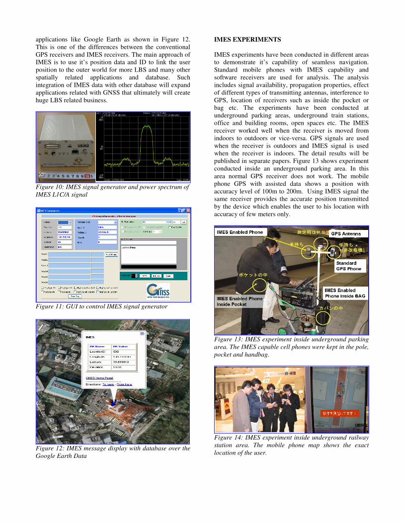
published in separate papers. Figure 13 shows experiment
conducted inside an underground parking area. In this
area normal GPS receiver does not work. The mobile
phone GPS with assisted data shows a position with
accuracy level of 100m to 200m. Using IMES signal the
same receiver provides the accurate position transmitted
by the device which enables the user to his location with
accuracy of few meters only.
Figure 13: IMES experiment inside underground parking
area. The IMES capable cell phones were kept in the pole,
pocket and handbag.
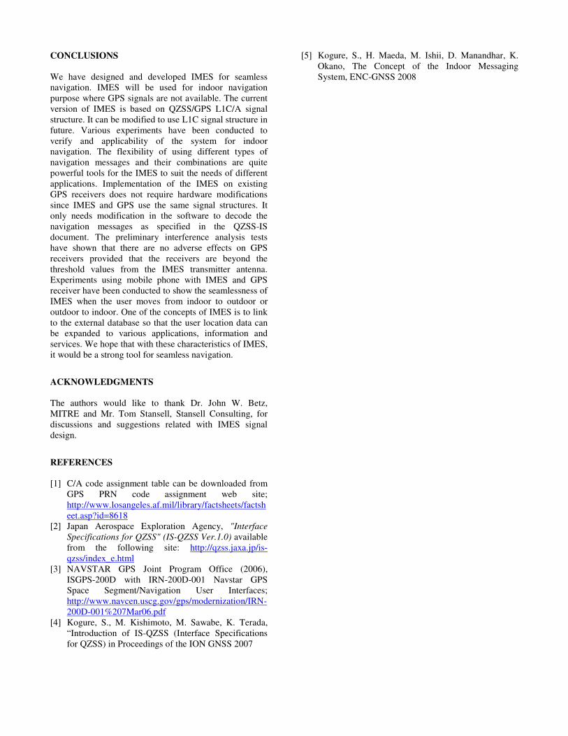
Figure 14: IMES experiment inside underground railway
station area. The mobile phone map shows the exact
location of the user.
CONCLUSIONS
We have designed and developed IMES for seamless
navigation. IMES will be used for indoor navigation
purpose where GPS signals are not available. The current
version of IMES is based on QZSS/GPS L1C/A signal
structure. It can be modified to use L1C signal structure in
future. Various experiments have been conducted to
verify and applicability of the system for indoor
navigation. The flexibility of using different types of
navigation messages and their combinations are quite
powerful tools for the IMES to suit the needs of different
applications. Implementation of the IMES on existing
GPS receivers does not require hardware modifications
since IMES and GPS use the same signal structures. It
only needs modification in the software to decode the
navigation messages as specified in the QZSS-IS
document. The preliminary interference analysis tests
have shown that there are no adverse effects on GPS
receivers provided that the receivers are beyond the
threshold values from the IMES transmitter antenna.
Experiments using mobile phone with IMES and GPS
receiver have been conducted to show the seamlessness of
IMES when the user moves from indoor to outdoor or
outdoor to indoor. One of the concepts of IMES is to link
to the external database so that the user location data can
be expanded to various applications, information and
services. We hope that with these characteristics of IMES,
it would be a strong tool for seamless navigation.
ACKNOWLEDGMENTS
The authors would like to thank Dr. John W. Betz,
MITRE and Mr. Tom Stansell, Stansell Consulting, for
discussions and suggestions related with IMES signal
design.
REFERENCES
[1] C/A code assignment table can be downloaded from
GPS PRN code assignment web site;
http://www.losangeles.af.mil/library/factsheets/factsh
eet.asp?id=8618
[2] Japan Aerospace Exploration Agency, "Interface
Specifications for QZSS" (IS-QZSS Ver.1.0) available
from the following site: http://qzss.jaxa.jp/is-
qzss/index_e.html
[3] NAVSTAR GPS Joint Program Office (2006),
ISGPS-200D with IRN-200D-001 Navstar GPS
Space Segment/Navigation User Interfaces;
http://www.navcen.uscg.gov/gps/modernization/IRN-
200D-001%207Mar06.pdf
[4] Kogure, S., M. Kishimoto, M. Sawabe, K. Terada,
“Introduction of IS-QZSS (Interface Specifications
for QZSS) in Proceedings of the ION GNSS 2007
[5] Kogure, S., H. Maeda, M. Ishii, D. Manandhar, K.
Okano, The Concept of the Indoor Messaging
System, ENC-GNSS 2008