Embed Size (px)
Citation preview

NASA Technical Memorandum 106404+_
ILJI"
Development of Phased Twin Flip-Flop Jets
Ganesh Raman
Sverdrup Technology, Inc.
Lewis Research Center Group
Brook Park, Ohio
and
Edward J. Rice
National Aeronautics and Space Administration
Lewis Research Center
Cleveland, Ohio
Prepared for the
ASME Winter Annual Meeting
sponsored by the American Society of Mechanical Engineers
New Orleans, Louisiana, November 28-December 3, 1993
(NASA-t_-I06404) DEVELOPMENT OFPHASED TWIN FLIP-FLOP J=TS (NASA)
lO p
N94-20563
Unclas
G3/02 0195107
https://ntrs.nasa.gov/search.jsp?R=19940016090 2018-05-20T22:30:18+00:00Z


DEVELOPMENT OF PHASED TWIN FLIP-FLOP JETS
Ganesh Raman _
Sverdrup Technology Inc.
Lewis Research Center Group
Brookpark OH 44142
Edward J. Rice s
NASA Lewis Research Center
Cleveland OH 44135
ABSTRACT
The flip-flop nozzle is a device that can produce an
oscillating jet flow without any moving parts. There isnow a renewed interest in such nozzles due to their
potential for use as excitation devices in practical
applications. An experiment aimed at developing twin
flip-flop jets that operate at prescribed frequencies and
phase differences was performed. The phasing was
achieved using two different nozzle interconnection
schemes. In one configuration the two jets flapped in-
phase and in another they flapped out-of-phase with
respect to each other. In either configuration the
frequencies of oscillation of both jets were equal. When
one of the jets was run at a constant high velocity and
the velocity of the second jet was increased gradually,
the higher velocity jet determined the frequency of
oscillation of both jets. The two flip-flop jet
configurations described in this paper could be used to
excite a primary jet flow in either an anti-symmetric
(sinuous) or a symmetric (varicose) mode.
NOMENCLATURE
B
b
d
dc
larger dimension of flip-flop attachment
larger dimension of rectangular slot nozzlediameter of feedback tubediameter of interconnection tube
f
H
h
L
Lc
L,fPaPo/Pa
S,sW
frequency of oscillation
smaller dimension of flip-flop attachment
smaller dimension of rectangular slot nozzle
length of feedback tube
length of interconnection tube
axial dimension of flip-flop nozzle attachment
ambient pressure
nozzle pressure ratio (NPR)
aspect ratio, B/H, b/hwidth of feedback slot
INTRODUCTION
In the 1970's pioneering work on the flip-flop nozzle
was done by Viets and his associates (Viers (1975),
Viets et al (1975a)). They showed that it is possible to
produce and sustain an oscillation of a subsonic jet flow
without any moving parts. Such oscillatory jets have
applications in fuel injectors (Viets et al (1975a)), foam
spreading (Viets et al (1975b)), unsteady ejectors (Viers
(1981)), and in two-phase flows (Morris et al (1992)).
In our previous work (Raman et al (1993)) the
operation of the flip-flop jet nozzle was extended to
supersonic flows. The potential for using such a device
for the control of practical shear flows is the motivation
for the present effort. Excitation from acoustic drivers
_Research Engineer
2Lewis Distinguished Research Associate, Retired

usedforcontrollingshearflowsinfundamentalresearchexperiments(CrowandChampagne(1971),Ahujaetal(1982),RamanandRice(1991))arenotlikelyto beeffectiveunderpracticalconditions.In recentyearsavarietyof shearflow controldeviceshavebeendeveloped.Examplesof novelexcitationdevicesincludethe"Whistlernozzle"(HillandGreene(1977)),theuseof piezoelectricactuators(WilsteandGlezer(1993)),jetsexcitedbynaturaland"induced"screech(RiceandRaman(1993)),anddual-modeacousticexcitationthatresultsin "bifurcated"jets(Parekhetal(1987)).Othertechniquesforflowmanipulationandmixingenhancementincludetheuseoftabs(AhujaandBrown(1989),Zamanet al (1993)),counterflow(Strykowskiet al (1992)),hydrodynamicexcitation(Brown andAhuja (1990)) andauxiliary jetimpingement(Davis(1982)).Theflip-flopjetprovidesyetanotherpossibilityforthecontrolofpracticalshearflows.
Therehasbeenarecentrenewalof interestin flip-flopjetsandsimilardevices.Thisisduetotheneedforapracticalexcitationdeviceforthecontrolofmixingandnoiseof supersonicjets. Schreck(1992a)reportedworkonanoscillatingjet producedbythealternatepumpingof air from bothsidesof thejet. In asubsequentstudySchreck(1992b)eliminatedthepumpingandusedscreechamplifiedbyaresonantcavitytoexcitethejet. However,it appearsthatsuchnozzlesareunsuitablefor useasprimarynozzlesdueto largelossesin thrust.Thethrustlossin aflip-flopnozzlewasmeasuredbyViets(1975)tobebetween10and40percent.Thisthrustlossmaybelowerin thenozzleof Schreck(1992b)becausetheflowdoesnotactuallyattachtobothwalls. However, estimates of thethrust loss for this nozzle are currently unavailable.
There have been previous attempts (Viets (1975)) to
interconnect the various elements of flip-flop nozzles in
order to achieve some desired phase relationships
between neighboring nozzles. However, in spite of thevarious configurations attempted, oscillation of the flow
was not achieved. Viets (1975) tested a nine element
nozzle for use as the primary nozzle in a low area ratio
ejector test, but each nozzle element oscillated
independently with no specific phase relationship to theother nozzles. It should be noted that in subsequent
work, Viets et al (1981) did operate a series of
mechanically controlled multiple fluidic jets at
controllable phases. However, the oscillating pressure
difference was created by rotating valves on either side
of the jet. The valves were rotated out of phase with
each other, so that one was open when the other was
closed. The resulting flow always attached to the
closed side and thus provided a jet that oscillated from
side to side. Their (Viets et al (1981)) motivation was
not the development of practical excitation devices but
the design and development of a pilot gust tunnel using
a linear array of such nozzles.
SCOPE
The objective of this work is to develop twin flip-flop
jets that can operate at a controllable frequency and
phase difference. Schemes to interconnect a pair of flip-
flop jet nozzles and operate them either in-phase (0
degrees phase difference) or out-of-phase (180 degrees
phase difference) with respect to each other aredescribed here. In contrast to the Viets (1981) work
using rotating valves that was described earlier, the
present work attempts to interconnect two flip-flopnozzles without moving parts, using only feedback tube
interconnections. To our knowledge, work on such twin
flip-flop jets operating at a desired phase relationshipand controllable frequency of oscillation has not been
reported before. The twin jets can provide either
symmetric or anti-symmetric fluid dynamic
perturbations that could be used to excite a larger scale
primary flow.
The work described in this paper should be viewed as
a unique "proof of concept" type of experiment.However, the optimization of nozzle parameters and
interconnection tubes was not attempted here. For such
an excitation technique to be viable for use in practical
applications, flip-flop exciters must be designed for
optimal performance.
EXPERIMENTAL DETAILS
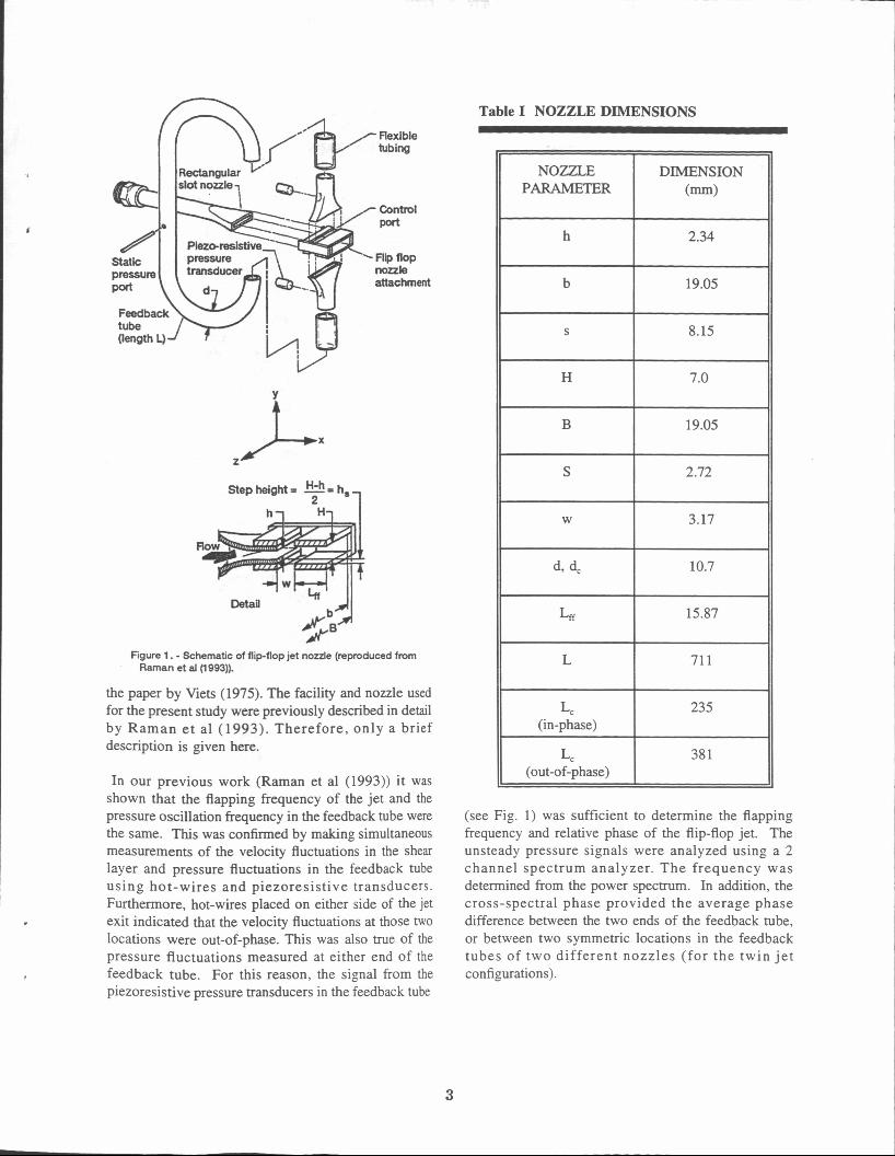
A schematic of the flip-flop jet nozzle reproduced from
Raman et al (1993) is shown in Figure 1. The nozzle
has three parts: the convergent rectangular slot nozzle,
a nozzle attachment with control ports, and a feedback
tube that connects the control ports. When the jet from
the rectangular slot nozzle (see Figure 1) exhausts into
the region between the two plates of the nozzle
attachment, the jet could attach to either wall (Coanda
effect). A small pressure gradient could cause the jet todetach from one wall and attach to the other. With the
help of a feedback tube this process can be repeated.
Details of the operation of such nozzles are available in
2
attachment
NOZZLE PARAMETER
h
b
S
H
B
z Ax
DIMENSION (mm>
2.34
19.05
8.15
7.0
19.05
Step height = = h, , h i H i
d, dc
Lff
L Figure 1. - Schematic of flip-flop jet nozzle (reproduced from Raman et al (r 993)).
the paper by Vie& (1975). The facility and nozzle used for the present study were previously described in detail by Raman e t a1 (1993). Therefore, only a brief description is given here.
10.7
15.87
71 1
In our previous work (Raman et a1 (1993)) it was shown that the flapping frequency of the jet and the pressure oscillation frequency in the feedback tube were the same. This was confirmed by making simultaneous measurements of the velocity fluctuations in the shear layer and pressure fluctuations in the feedback tube using hot-wires and piezoresistive transducers. Furthermore, hot-wires placed on either side of the jet exit indicated that the velocity fluctuations at those two locations were out-of-phase. This was also true of the pressure fluctuations measured at either end of the feedback tube. For this reason, the signal from the piezoresistive pressure transducers in the feedback tube
Lc (in-phase)
Table I NOZZLE DIMENSIONS
235
2.72
W 1 3.17
LC I 381 (out-of-phase)
(see Fig. 1) was sufficient to determine the flapping frequency and relative phase of the flip-flop jet. The unsteady pressure signals were analyzed using a 2 channel spectrum analyzer. The frequency was determined from the power spectrum. In addition, the cross-spectral phase provided the average phase difference between the two ends of the feedback tube, or between two symmetric locations in the feedback tubes of two different nozzles (for the twin j e t configurations).
3
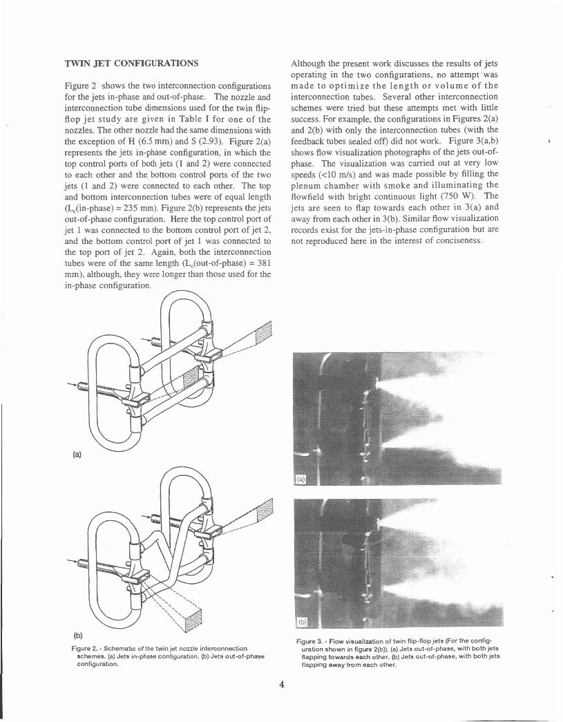
TWIN JET CONFIGURATIONS
Figure 2 shows the two interconnection configurations for the jets in-phase and out-of-phase. The nozzle and interconnection tube dimensions used for the twin flip- flop je t study are given in Table I for one of the nozzles. The other nozzle had the same dimensions with the exception of H (6.5 mm) and S (2.93). Figure 2(a) represents the jets in-phase configuration, in which the top control ports of both jets (1 and 2) were connected to each other and the bottom control ports of the two jets (1 and 2) were connected to each other. The top and bottom interconnection tubes were of equal length (L,(in-phase) = 235 mm). Figure 2(b) represents the jets out-of-phase configuration. Here the top control port of jet 1 was connected to the bottom control port of jet 2, and the bottom control port of jet 1 was connected to the top port of jet 2. Again, both the interconnection tubes were of the same length (L,(out-of-phase) = 381 mm), although, they were longer than those used for the in-phase configuration.
n
Although the present work discusses the results of jets operating in the two configurations, no attempt was made to opt imize the length o r volume of the interconnection tubes. Several other interconnection schemes were tried but these attempts met with little success. For example, the configurations in Figures 2(a) and 2(b) with only the interconnection tubes (with the feedback tubes sealed off) did not work. Figure 3(a,b) h
shows flow visualization photographs of the jets out-of- phase. The visualization was carried out at very low speeds (<lo d s ) and was made possible by filling the plenum chamber with smoke and illuminating the flowfield with bright continuous light (750 w>. The jets are seen to flap towards each other in 3(a) and away from each other in 3(b). Similar flow visualization records exist for the jets-in-phase configuration but are not reproduced here in the interest of conciseness.
Figure 2. - Schematic of the twin jet nozzle interconnection schemes. (a) Jets in-phase configuration. (b) Jets outof-phase Configuration.
Figure 3. - Flow visualization of twin flip-flop jets (For the config- uration shown in figure 2(b)). (a) Jets out-of-phase. with both jets flapping towards each other. (b) Jets out-of-phase. with both jets flapping away from each other.
4
RESULTS AND DISCUSSION TWIN JETS IN-PHASE
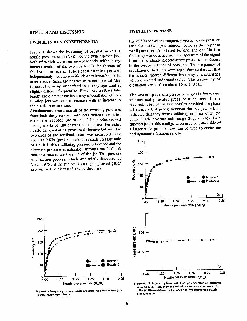
TWIN JETS RUN INDEPENDENTLY
Figure 4 shows the frequency of oscillation versus
nozzle pressure ratio (NPR) for the twin flip-flop jets,
both of which were run independently without anyinterconnection of the two nozzles. In the absence of
the interconnection tubes each nozzle operated
independently with no specific phase relationship to the
other nozzle. Since the nozzles were not identical (due
to manufacturing imperfections), they operated at
slightly different frequencies. For a fixed feedback tube
length and diameter the frequency of oscillation of both
flip-flop jets was seen to increase with an increase in
the nozzle pressure ratio.
Simultaneous measurements of the unsteady pressures
from both the pressure transducers mounted on eitherend of the feedback tube of one of the nozzles showed
the signals to be 180 degrees out of phase. For either
nozzle the oscillating pressure difference between thetwo ends of the feedback tube was measured to be
about 14.2 KPa (peak-to-peak) at a nozzle pressure ratio
of 1.8. It is this oscillating pressure difference and the
alternate pressure equalization through the feedback
tube that causes the flapping of the jet. This pressure
equalization process, which was briefly discussed by
Viers (1975), is the subject of an ongoing investigation
and will not be discussed any further here.
255 -
200
100
50
01.00
_ ._'_ _ --*
_"--_'_ Nozzle 1
• .... _ Nozzle 2
I I I I I1-25 1.55 1.75 2.00 2-25
Nozzlepressureratio(Po/Pa)
Figure 4. - Frequency versus nozzle pressure ratio for the twin jetsoperating independently.
Figure 5(a) shows the frequency versus nozzle pressureratio for the twin jets interconnected in the in-phase
configuration. As stated before, the oscillation
frequency was obtained from the spectrum of the signal
from the unsteady piezoresistive pressure transducers
in the feedback tubes of both jets. The frequency of
oscillation of both jets were equal despite the fact that
the nozzles showed different frequency characteristics
when operated independently. The frequency ofoscillation varied from about 10 to 170 Hz.
The cross-spectrum phase of signals from two
symmetrically located pressure transducers in the
feedback tubes of the two nozzles provided the phase
difference ( 0 degrees) between the two jets, which
indicated that they were oscillating in-phase over the
entire nozzle pressure ratio range (Figure 5(b)). Twin
flip-flop jets in this configuration used on either side of
a larger scale primary flow can be used to excite the
anti-symmetric (sinuous) mode.
250 --
200
hi-r
150
loo_m
5O
D
m _ "m't_
i0 ! I 1,, t I (a)}
1.00 1-25 1.50 1.75 2.00 2.25
Nozzle pressure ratio (Po/Pa)
t----_ "0 Nozzle 1• .... "l Nozzle 2
"[3
I¢
qD
| -lOOJ_13.
100--
It4F--m--- -It .... -41 _ -,II ..... II .... 41--I
1.00I ( I I (b) f
1.25 1.50 1.75 2.00 2.25
Nozzle pressure ratio (Po/Pa)
Figure 5. - Twin jets in-phase, with both jets operated at the samevelocities. (a) Frequency of oscillation versus nozzle pressure
ratio. (13)Phase difference between the two jets versus nozzlepressure ratio.
5

TWIN JETS OUT-OF-PHASE
Figures 6(a) shows the frequency of oscillation versus
nozzle pressure ratio for the twin jets interconnected in
the out-of- phase configuration. The frequencies of the
oscillations of both jets were again equal. The
frequency of oscillation here varied from 10 to 155 Hz.
The difference in the frequency of oscillation between
the two configurations was due to the different lengthsand volumes of interconnection tubes which resulted in
a different equivalent feedback tube length for the two
configurations (see Table I). The interconnection tubes
for the out-of-phase configuration were longer, resulting
in lower frequencies of oscillation.
The pressure signals from two symmetrically locatedsensors in the feedback tubes of the two nozzles were
about 180 degrees out-of-phase, which indicated that
the jets were oscillating out-of-phase over the entire
nozzle pressure ratio range(Figure 6(b)). Hip-flop jets
in the out-of phase configuration used on either side of
a larger scale primary flow can be used to excite the
symmetric (varicose) mode.250 -
200 -
N
50
01.00
o
'o 100
)"0o
g -100 --J=n
5 1.00
_m-_--o-- ._....._"
m" O-----'_ Nozzle1
U .... • Noz_e2
I I I I (a) I
1.25 1.50 1.75 2.00 2.25Nozzlepressureratio (Po/Pa)
m
,•.--w" • • • -.m--- n--l--mm--m
I I I I (b)l
1.25 1.50 1.75 2.00 2.25
Nozzlepressureratio(Po/Pa)
Figure 6. - Twin jets out-of-phase, with both jets operated at the
same velocities. (a} Frequency of oscillation versus nozzle
pressure ratio. (b) Phase difference between the two jets versus
nozzle pressure ratio.
PHASED TWIN JETS AT DIFFERENTVELOCITIES
Figure 7(a,b) shows the frequency of oscillation and
phase difference between the two jets versus nozzle
pressure ratio for twin jets operating at differentvelocities. For these tests nozzle 2 was run at a
constant (approximately) nozzle pressure ratio of 2.1,
while that of nozzle 1 was varied gradually from 1.1 to
1.8. The frequency of oscillation, however, remained
constant (for both jets) at around 170 Hz for the in-
phase configuration (Figure 7(a)) and around 155 Hz
for the out-of-phase configuration (Figure 8(a)). As
mentioned earlier, this difference in the frequency of
oscillation between the two configurations was due to
the different lengths and volumes of interconnection
tubes for the two configurations.
250-
200
N"r
150e-¢D
50 m
la)01.00
m
a..•..e.. ...... • ............. --. •
D---_O Nozzle1[] .... m Nozzle2
Nozzle2 was runat a constantNPRwhiletheNPRof nozzle1 wasvaried
I I 1 t I1.25 1.50 1.75 2-00 2.25
Nozzlepressureratio(Po/Pa)
OIo
-o 100ooe-
'UID
= -_
B--R---B. ........ • ................... -411
Co)
1.00I I I I I
1.25 1.50 1.75 2-00 2.25
Nozzlepressureratio(Po/Pe)
Figure 7. - Twin jets in-phase, with both jets operated at different
velocities. (a) Frequency of oscillation versus nozzle pressure
ratio. (b) Phase difference between the two jets versus nozzle
pressure ratio.

The nozzle that was operating at a constant (high)
nozzle pressure ratio in Figures 7(a) and 8(a) was
controlling the frequency of oscillation of both jets,
while the nozzle that was operating at lower nozzle
pressure ratios was behaving as a "slave" jet. This is
an important finding in itself because the twin flip-flop
configuration now provides the means to control the
frequency of oscillation of one of the jets that is
independent of the nozzle pressure ratio of that jet.
With the twin jet configuration, the control jet could be
used to keep the frequency of a "slave" jet constant
over the range of nozzle pressure ratios of the "slave"jet. From Figures 7(b) and 8(b) it can be seen that
even when the jets were operated at different speeds it
was possible to maintain either the in-phase (Figure
7(b)) or the out-of-phase (Figure 8(b)) relationship
between the two jets.
250 -
N
"I"
Q-i
200
150
100 -
50 --
01.00
E
_ irlp..4p_._.... _ ..... -4 i41,
0---_"_D Nozzle1• .... ._ Nozzle2
Nozzle2 wasrunat a constantNPRwhile theNPRof nozzleI wasvaried
I I I I1.25 1.50 1.75 2.00
Nozzlepressureratlo(Po/Pa)
I2.25
O0
100¢Doe-
"0
CD
-100/..n
n
B--II--- -m ............ -B- ................. •
Col l I I I I1.00 1.25 1.50 1.75 2.00 2.25
Nozzlepressureratio(Po/Pa)
Figure8. - Twinjetsout-of-phase,withbothjetsoperatedatdifferentvelocities.(a)Frequencyof oscillationversusnozzlepressureratio.(b)Phasedifferencebetweentwojets versusnozzlepressureratio.
COMMENTS ON APPLICABILITY
For the flip-flop exciter system to be ata'active for use
in practical applications, exciter nozzles must be
designed for optimal performance. For the efficient
operation of such a system with minimum thrust loss,
the mass flux through the exciter jets should be
negligible compared to that through the primary jet.
Consequently, the dimensions of the exciter jets need to
be relatively small, yet the unsteady excitation levels in
the shear layer of the primary jet need to be large.
The important parameters to be considered for the
efficient operation of a primary jet with a flip-flop
exciter system are: frequency matching (between exciter
and primary flow instability), nozzle sizing, velocity
perturbation level produced, and selection of the
appropriate mode of excitation (anti-symmetric or
symmetric, depending on the primary flow instability).
Future work should focus on achieving the goalsmentioned above.
NOTE ON MEASUREMENT UNCERTAINTY
Estimates for the uncertainty in the measurements
presented in this work were obtained using the methodsdescribed by Moffat (1985). The calibration
uncertainty, which takes into account the uncertainties
associated with the supply pressure, static pressureprobe, and the pressure transducers was estimated to be
about 1.5%. In addition, the first order uncertainty wasestimated to be about 0.3%. The resultant total
uncertainty was 1.529%.
CONCLUDING REMARKS
(1) It was found that it is possible to interconnect two
flip-flop nozzles to operate in-phase or out-of-phase.Despite the fact that the nozzles were not identical (due
to manufacturing imperfections), the jets operated at the
same frequency when the feedback loops were
interconnected. This frequency "locking" was observed
in both configurations (in-phase and out-of-phase). With
such multiple, small scale, interconnected devices it
would be possible to excite a larger scale primary flow
in either an anti-symmetric (flapping) or a symmetric
(plane wave) mode.
(2) When one of the jets was run at a constant high
velocity and the velocity of the other jet was increased
gradually, the higher constant velocity jet determined

thefrequencyof oscillation of both jets. Despite the
unequal velocities the jets were capable of operating in
either the in-phase or the out-of-phase configuration.
(3) In this paper a unique "proof of concept" type of
experiment was described. However the optimization of
nozzle parameters and interconnection tubes was not
attempted here. For this technique to be viable in
practical applications, flip-flop exciters must be
designed for optimal performance.
ACKNOWLEDGEMENTS
The authors would like to thank the following
individuals for contributing to this work: Dr. B.
Reichert, Dr. J. Wilson, Dr. K. Dugas, Mr. M. Hailye,Mr. D. Cornelius and Mr. R. Fallert. This work would
not have been possible if not for the extensive ground
work done by Dr. H. Viets and his associates.
REFERENCES
Ahuja, K.K., Lepicovsky, J., Tam, C.K.W., Morris, EJ.,
and Burrin, R.H., 1982, "Tone-excited Jets, Theory and
Experiments", NASA CR-3538.
Ahuja, K.K., and Brown, W.H., 1989, "Shear Flow
Control by Mechanical Tabs", A/AA Paper 89-0994.
Brown, W.H., and Ahuja, K.K., 1990, "Jet Mixing
Enhancement by Hydrodynamic Excitation", AIAA
Paper 90-4005.
Crow, S.C., and Champagne, F.H., 1971, "OrderlyStructure in Jet Turbulence", J. Fluid Mech., Vol. 48,
pp. 547-591.Davis, M.R., 1982, "Variable Control of Jet Decay",
AIAA J., Vol. 20, pp. 606-609.
Hill, W.G., and Greene, P.R., 1977, "Increased
Turbulent Jet Mixing Rates Obtained by Self-Excited
Acoustic Oscillations," Journal of Fluids Engineering,
Transactions of the ASME, pp 520-525.
Moffat, R.J., 1985, "Using Uncertainty Analysis in the
Planning of an Experiment," Journal of Fluids
Engineering, Trans. ASME, Vol. 107, pp 173-178.Morris, G.J., Jurewicz, J.T., and Palmer, G.M., 1992,
"Gas-Solid Flow in a Fluidicaily Oscillating Jet",
Journal of Fluids Engineering, Trans ASME, Vol. 114,
pp. 362-366.Parekh, D.E., Reynolds, W.C., and Mungal, M.G.,
1987, "Bifurcation of Round Air Jets by Dual-Mode
Acoustic Excitation", AIAA Paper 87-0164.
Raman, G., and Rice, E.J., 1991, "Axisymmetric Jet
Forced by Fundamental and Subharmonic Tones," AIAA
J., Vol. 29, pp. 1114-1122.
Raman, G., Ha/lye, M., and Rice, E.J., 1993, "Flip-
Flop Jet Nozzle Extended to Supersonic Flows", AIAA
J., Vol. 31, No. 6, pp. 1028-1035.
Rice, E.J., and Raman, G., 1993, "Enhanced Mixing of
a Rectangular Supersonic Jet by Natural and Induced
Screech", A/AA Paper 93-3263.
Schreck, S., Ho, C.M., and Sarmiento, 1992a "Noise
Radiated from Axisymmetric and Asymmetric Jets,"
A/AA Paper 92-02044.
Schreck, S., 1992b "Application of a Flip-Flop Nozzle
on Plume Mixing Enhancement", Presented at the First
NASA/Industry High Speed Research, Nozzle
Symposium, NASA LeRC, Cleveland OH, Nov. 17-19,
1992 ( to be published as a NASA CP).
Strykowski, P.J., Krothapalli, A., and Wishart, D.,
1992, "The Enhancement of Mixing in High Speed
Heated Jets Using a Counterflowing Nozzle", AIAA
Paper 92-3262.Wiltse, J.M., and Glezer, A., 1993, "Manipulation of
Free Shear Flows using Piezoelectric Actuators",Submitted to J. Fluid Mech.
Viets, H., 1975, "Flip-Flop Jet Nozzle", AIAA J., Vol.
13, pp 1375-1379.Viets, H., Blaster, D., Toms, H.L. Jr., 1975a, "Time
Dependent Fuel Injectors," AIAA Paper 75-1305.Viets, H., Balster, D., and Toms, H.L. Jr., 1975b,
"Feasibility study of Unsteady Foam Generators",
DOD-AGFSRS-75-6, Wright-Patterson Air Force Base.
Viets, H., 1981, "Unsteady Ejectors," Proceedings of
the NATO/AGARD Meeting on Fluid Dynamics of Jet
Flows with Applications to V/STOL, NATO/AGARD
CP-308, pp. 21.1-21.12.
Viets, H., Ball, M., and Piatt, M., 1981, "Experiments
in a Subscale Pilot Gust Tunnel," AIAA J., Vol. 19, pp.820-822.
Zaman, K.B.M.Q., Reeder, M.F., and Samimy, M.,
1993, " Control of an Axisymmetric Jet Using Vortex
Generators", Submitted to Phys. Fluids A.


Form ApprovedREPORT DOCUMENTATION PAGE OMB NO. 0704-0188
Public reporting burden for this collection of information is es_mated to average 1 hour pc( response, inc_ding the time for reviewing instructions, searching existing data sources,
lind maJntainlng the data needed, ancl completing and reviewing the col_chon of information. Send comments regarding this burcten estimate or any other aspect of this
collec'don o_ infommbon, inclu(ling suggestions _ reducing this burden, to Washington Headquarters Se_/ices, Directorate for tnformattor_ Operations _ Reports, 1215 Jefferson
Davis Highway, Suite 1204, Arlington. VA 22202-4302. and to the Office of Management and Budget, Paperwork Reduction Proiect (0704-0188), Washington. DC 20503.
1. AGENCY USE ONLY (Leave blank) 2. REPORT DATE
November 1993
4. TITLE AND SUBTITLE
Development of Phased Twin Flip-Flop Jets
6. AUTHOR(S)
Ganesh Raman and Edward J. Rice
7. PERFORMING ORGANIZATION NAME(S) AND ADDRESS(ES)
National Aeronautics and Space Administration
Lewis Research Center
Cleveland, Ohio 44135-3191
9. SPONSORINGIMONITORING AGENCY NAME(S) AND ADDRESS(ES)
National Aeronautics and Space Administration
Washington, D.C. 20546-0001
3. REPORT TYPE AND DATES COVERED
Technical Memorandum
5. FUNDING NUMBERS
WU-505-62-52
8. PERFORMING ORGANIZATIONREPORT NUMBER
E-7609
10. SPONSORING/MONITORINGAGENCY REPORT NUMBER
NASA TM- 106404
11. SUPPLEMENTARY NOTES
Prepared for the ASME Winter Annual Meeting, sponsored by the American Society of Mechanical Engineers, New Orleans, Louisiana,
November 28-December 3, 1993. Ganesh Raman, Sverdrup Technology, Inc. Lewis Research Center Group, 2001 Aerospace Parkway,
Brook Park, Ohio 44142 (work funded by NASA Contract NAS3--25266). Responsible person, Edward J. Rice, (216) 433--3607.
12a. DISTRIBUTION/AVAILABILITY STATEMENT
Unclassified - Unlimited
Subject Category 02
12b. DISTRIBUTION CODE
13- ABSTRACT (Maximum 200 words)
The flip-flop nozzle is a device that can produce an oscillating jet flow without any moving parts. There is now a
renewed interest in such nozzles due to their potential for use as excitation devices in practical applications. An
experiment aimed at developing twin flip-flop jets that operate at prescribed frequencies and phase differences was
performed. The phasing was achieved using two different nozzle interconnection schemes. In one configuration the
two jets flapped in-phase and in another they flapped out-of-phase with respect to each other. In either configuration
the frequencies of oscillation of both jets were equal. When one of the jets was run at a constant high velocity and the
velocity of the second jet was increased gradually, the higher velocity jet determined the frequency of oscillation of
both jets. The two flip-flop jet configurations described in this paper could be used to excite a primary jet flow in either
an anti-symmetric (sinuous) or a symmetric (varicose) mode.
14. SUBJECT TERMS
Flip-Flop jets; Twin jets; Acoustic excitation; Unsteady jets; Oscillatory jets; Excitation
devices; Shear flow control; Unsteady ejectors
17. SECURITY CLASSIFICATIONOF REPORT
Unclassified
NSN 7540-01-280-5500
18. SECURITY CLASSIFICATIONOF THIS PAGE
Unclassified
19. SECURITY CLASSIFICATIONOF ABSTRACT
Unclassified
15. NUMBER OF PAGES10
16. PRICE CODE
A0220. LIMn'A11ON OF ABSTRACT
Standard Form 298 (Rev. 2-89)Prescribed by ANSI Std. Z39-18
298-1 02

g_o_ _mr __w
_0