Embed Size (px)
Citation preview
Development of Nut-Inlaying Technique in Hydroformed Componentby Hydro-Burring
Masaaki Mizumura, Koichi Sato+1 and Yukihisa Kuriyama+2
Forming Technologies R&D Center, Steel Research Laboratory, Nippon Steel Corporation, Futtsu 293-8511, Japan
Hydroforming has certain advantages, for example integration of components and weight reduction, but it also has some disadvantages.One disadvantage is the difficulty in joining a hydroformed component to another part. Therefore hydro-burring after hydro-piercing in ahydroforming die has been investigated. The internal pressure during hydro-burring is found to have a large effect on the burring limit. Thehydroformed component can be joined to another part with the thread tapped at the hydro-burring portion. However, it is difficult to tap thin-walled tubes. Therefore a new technique, a nut-inlaying method in a hydroformed component, has been developed. As a result, thin-walledhydroformed components can also be joined to other parts using this nut-inlaying method. [doi:10.2320/matertrans.MF201105]
(Received August 10, 2011; Accepted December 5, 2011; Published April 25, 2012)
Keywords: hydroforming, piercing, burring, nut, joining, crack, tensile test, internal pressure
1. Introduction
Recently, hydroforming technologies have often beenapplied to automobile components.1) Hydroforming hasmany advantages over press forming. For example, whenforming an engine cradle, many steel plates are necessary inthe case of conventional press forming; however, the samepart can be formed from a single tube with hydroforming,which also serves to reduce the overall weight of theautomobile by eliminating welding flanges. However, it alsohas some disadvantages, one of which is that the hydro-forming cycle takes longer than press forming since it takestime to fill the tube with water. In addition, it is oftenreputed to be difficult to join hydroformed componentsto other parts.2) Since hydroformed components have noflanges, they cannot be spot welded or bolted to other parts.The objective of this research is the development of a newattachment method between hydroformed components andother parts.
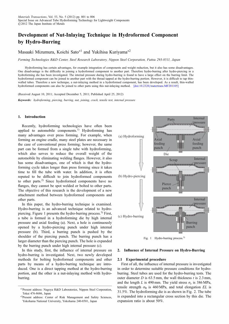
In this paper, the hydro-burring technique is examined.Hydro-burring is an advanced technique related to hydro-piercing. Figure 1 presents the hydro-burring process.3) First,a tube is formed in a hydroforming die by high internalpressure and axial feeding (a). Next, a hole is continuouslyopened by a hydro-piercing punch under high internalpressure (b). Third, a burring punch is pushed by theshoulder of the piercing punch. The burring punch has alarger diameter than the piercing punch. The hole is expandedby the burring punch under high internal pressure (c).
In this study, first, the influence of internal pressure onhydro-burring is investigated. Next, two newly developedmethods for bolting hydroformed components and otherparts by means of a hydro-burring technique are intro-duced. One is a direct tapping method at the hydro-burringportion, and the other is a nut-inlaying method with hydro-burring.
2. Influence of Internal Pressure on Hydro-Burring
2.1 Experimental procedureFirst of all, the influence of internal pressure is investigated
in order to determine suitable pressure conditions for hydro-burring. Steel tubes are used for the hydro-burring tests. Theouter diameter D is 63.5mm, the wall thickness t is 2.3mm,and the length L is 490mm. The yield stress ·y is 386MPa,tensile strength ·B is 460MPa, and total elongation EL is31.5%. The hydroforming die is as shown in Fig. 2. The tubeis expanded into a rectangular cross section by this die. Theexpansion ratio is about 50%.
Pierce punch
Burring punch
Internal pressure
Parts
Axial feeding punch
Die
(a) Hydroforming
(b) Hydro-piercing
(c) Hydro-burring
Scrap
Axial feeding punch
Internal pressure
Internal pressure
Fig. 1 Hydro-burring process.3)
+1Present address: Nagoya R&D Laboratories, Nippon Steel Corporation,Tokai 476-8686, Japan
+2Present address: Center of Risk Management and Safety Sciences,Yokohama National University, Yokohama 240-8501, Japan
Materials Transactions, Vol. 53, No. 5 (2012) pp. 801 to 806Special Issue on Advanced Tube Hydroforming Technology for Lightweight Components©2012 The Japan Institute of Metals

In this experimental process, firstly, all tubes are formedunder the same load conditions, and the same hydroformedshapes are obtained. Maximum internal pressure p is 200MPaand the final axial feed ¤f is 50mm. After this first hydroform-ing step, hydro-piercing and hydro-burring tests are conduct-ed under varying internal pressures pb, from 25 to 200MPa.
The position of the hydro-piercing and hydro-burring is thecenter of the hydroformed component, as shown in Fig. 2.Details of the hydro-piercing and hydro-burring punch sizesare shown in Fig. 3. In this figure, d1 and d2 refer to thepiercing diameter and burring diameter, respectively. In allthese tests, the burring diameter d2 was fixed at 20mm.However, the piercing diameters d1 were 8, 10, or 12mm.Consequently, the expansion burring ratios ¬ shown in eq. (1)are 150, 100 or 66.7%.
¬ ¼ d2 � d1d1
� 100 ð%Þ ð1Þ
In respect of the corner radius at the top of each punch,these sizes are also shown in Fig. 3. The corner radius at thetop of hydro-piercing punch R1 is set at 0mm in order toensure a hole is made. On the other hand, the top of thehydro-burring punch R2 is fixed at 2mm in order to create aburring shape.
2.2 Experimental resultsFigure 4 shows a sample after the hydro-burring test.3) In
this case, the internal pressure during hydro-burring was
200MPa and the expansion burring ratio is 100%. In thisfigure, a burring shape with a 20-mm inner diameter isformed on the inside of the hydroformed component.
Next the influence of internal pressure during hydro-burring on the hydro-burring limit is investigated. Theburring limit is generally evaluated by means of a holeexpansion test. In this conventional test method, the hole-expanding ratio is estimated by measuring the edge diameterupon penetration of a crack. However cracking of the edgecannot be observed during a hydro-burring test. In thesehydro-burring tests, the hydro-burring limit is evaluated inpost-test observations. A sample is cut off from the burringportion after the hydro-burring test. Then, the edge of thehole is observed and each crack is classified as one of threetypes as shown in Fig. 5, namely: (1) Non-penetrating crack,(2) Penetrating crack, and (3) Large crack.
Figure 6 shows the effect of internal pressure duringhydro-burring on the hydro-burring limit. It is found that thehydro-burring limit is high in the case of an extremely highinternal pressure of 200MPa. The reason is thought to bethat hydrostatic pressure inhibits voids at the edge fromgrowing.4) However, except in the case of extremely highinternal pressure, the hydro-burring limit rises with adecrease in internal pressure. Then, hardness at the edgeafter hydro-piercing but before hydro-burring is measured inorder to investigate the reasons for the aforementioned trend.Figure 7 shows the average hardness measured at a depth of0.1mm from the edge surface. It is apparent that the hardnessincreases with the rise in internal pressure. It is thought thatstress is concentrated locally and then the hole edge isdamaged in the case of high internal pressure. As a result, thehydro-burring limit rises at low internal pressures because ofthe lower hardness at the hole edge.
Figure 8 shows the influence of internal pressure on theburring shape. It is clear that the drop height declines as theinternal pressure increases. Consequently, high internal pres-sure is more desirable during the hydro-burring step in orderto ensure a compact burring shape. However in respect ofedge cracking during hydro-burring, low internal pressure ismore desirable. In order to resolve these conflicting problems,a new loading condition has been developed involving a two-step pressure raising method. First, hydro-piercing and hydro-burring are conducted at low internal pressure, since this isdesirable to inhibit edge cracking. Then the internal pressureis steadily raised to lower the drop shape. Figure 9(a) shows a
R2R1
d1
d2
822
Fig. 3 Size details of hydro-piercing and hydro-burring punches.
Outer side
Hydroformed component Inner side
pB=200 MPa d1=10 mm κκ =100 %
20mm
20mm
Fig. 4 Sample after hydro-burring test.3)
500
100 100200
63 95
63.5
A
A
A-A
R5.5
Burring position
Fig. 2 Hydroforming die.
M. Mizumura, K. Sato and Y. Kuriyama802

sample taken out after the first step of raising the pressure at alow internal pressure of 25MPa. In this step, the drop heightis 4.6mm. On the other hand, Fig. 9(b) shows a sampleobtained after the second pressure-raising step from 25 to200MPa. In this final step, the drop height becomes 2.6mm.The two-step pressure raising method proves to be effectivefor producing a good burring shape with a low drop heightand devoid of edge cracks.
3. Development of Bolting Method between Hydro-formed Component and Other Parts
3.1 Tapping at burring position after hydro-burringA suitable method for hydro-burring can be obtained via
the aforementioned investigation. Next, bolting betweenhydroformed components and other parts with this hydro-burring method was investigated. First, a sample with tappingafter hydro-burring was created as shown in Fig. 10. In thismethod, first, hydroforming, hydro-piercing and hydro-burring are conducted in the hydroforming die. Then thehydro-burred component is removed from the die, and istapped with a size M22 in the hydro-burring position. As aresult, this hydroformed component can be joined with a boltto other parts using this tapped thread.
3.2 Nut-inlaying technique into hydroformed compo-nent
The aforementioned method can be applied to thick tubes,but not to thin tubes, since thin-walled tubes cannot be tapped.In addition, the thread length is affected by the ratio of theburring diameter to the piercing diameter, and not enoughthread length can be obtained in the case of tube materialswith low formability, i.e. a low hole-expanding ratio. There-fore, a new bolting method applicable to thin hydroformedcomponents has been developed. This method is called thenut-inlaying technique in hydroformed components.
An outline of this process is shown in Fig. 11.3) The basicprocess is similar to the hydro-burring process shown inFig. 1. In the first step, hydroforming is performed. Thesecond step involves hydro-piercing, and third step is thehydro-burring. However in this case, the hydro-burring
Inner side
Test specimen after hydro-burring test
p=100 MPad1=12 mmR2=2 mm
p=150 MPad1=10 mmR2=2 mm
p=150 MPad1=8 mmR2=2 mm
(1) Non-penetrating crack
(2) Penetrating crack(3) Large crack Classification
Fig. 5 Classification of edge crack.
0
20
40
60
80
100
120
140
160
0 50 100 150 200
Exp
ansi
on r
atio
κ
/%
Internal pressure during hydro-burring pb /MPa
:(1) Non-penetrating crack:(2) Penetrating crack:(3) Large crack
Fig. 6 Effect of internal pressure on hydro-burring limit.
200
210
220
230
240
Har
dnes
s at
hol
e ed
ge /H
V 0
.2
Internal pressure during hydro-piercingpp /MPa
d1=10 mmκ =100 %
Fig. 7 Effect of internal pressure on hardness at hole edge after hydro-piercing.
0
1
2
3
4
5
6
0 50 100 200150
Dro
p he
ight
h
/mm
Internal pressure during hydro-burring pb /MPa
66.7
100.0
150.0
κ /%
h /mm
Fig. 8 Effect of internal pressure on drop height after hydro-burring.
Development of Nut-Inlaying Technique in Hydroformed Component by Hydro-Burring 803
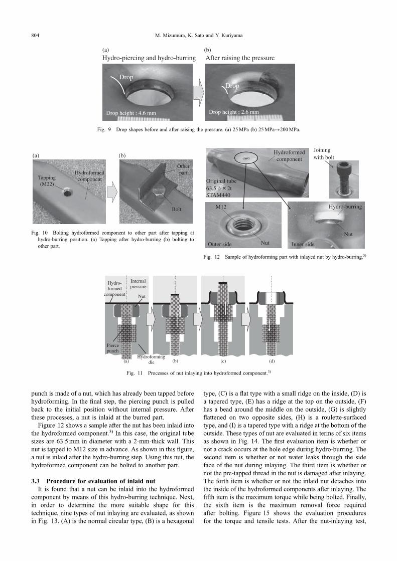
punch is made of a nut, which has already been tapped beforehydroforming. In the final step, the piercing punch is pulledback to the initial position without internal pressure. Afterthese processes, a nut is inlaid at the burred part.
Figure 12 shows a sample after the nut has been inlaid intothe hydroformed component.3) In this case, the original tubesizes are 63.5mm in diameter with a 2-mm-thick wall. Thisnut is tapped to M12 size in advance. As shown in this figure,a nut is inlaid after the hydro-burring step. Using this nut, thehydroformed component can be bolted to another part.
3.3 Procedure for evaluation of inlaid nutIt is found that a nut can be inlaid into the hydroformed
component by means of this hydro-burring technique. Next,in order to determine the more suitable shape for thistechnique, nine types of nut inlaying are evaluated, as shownin Fig. 13. (A) is the normal circular type, (B) is a hexagonal
type, (C) is a flat type with a small ridge on the inside, (D) isa tapered type, (E) has a ridge at the top on the outside, (F)has a bead around the middle on the outside, (G) is slightlyflattened on two opposite sides, (H) is a roulette-surfacedtype, and (I) is a tapered type with a ridge at the bottom of theoutside. These types of nut are evaluated in terms of six itemsas shown in Fig. 14. The first evaluation item is whether ornot a crack occurs at the hole edge during hydro-burring. Thesecond item is whether or not water leaks through the sideface of the nut during inlaying. The third item is whether ornot the pre-tapped thread in the nut is damaged after inlaying.The forth item is whether or not the inlaid nut detaches intothe inside of the hydroformed components after inlaying. Thefifth item is the maximum torque while being bolted. Finally,the sixth item is the maximum removal force requiredafter bolting. Figure 15 shows the evaluation proceduresfor the torque and tensile tests. After the nut-inlaying test,
Tapping (M22)
Hydroformed component
Bolt
Other part
(a) (b)
Fig. 10 Bolting hydroformed component to other part after tapping athydro-burring position. (a) Tapping after hydro-burring (b) bolting toother part.
Internal pressure
Hydro-formed
component Nut
Pierce punch
Hydroforming die(a) (b) (c) (d)
Fig. 11 Processes of nut inlaying into hydroformed component.3)
Hydroformed component
Hydro-burring
Inner sideOuter side
M12
Nut
Nut
Original tube63.5 2tSTAM440
Joining with bolt
Fig. 12 Sample of hydroforming part with inlayed nut by hydro-burring.3)
DropDrop
Hydro-piercing and hydro-burring After raising the pressure
Drop height : 4.6 mm Drop height : 2.6 mm
(a) (b)
Fig. 9 Drop shapes before and after raising the pressure. (a) 25MPa (b) 25MPa¼200MPa.
M. Mizumura, K. Sato and Y. Kuriyama804

a rectangular sample is cut off from the hydroformedcomponent including the inlaid nut. Then, this specimen isjoined by a bolt and washer to another plate. In the torquetest, it was assumed that the torque criterion is 90N·m. Thisvalue is the torque limit for the washer. Subsequently, thiscross-shaped specimen is used in the tensile test. In this test, atensile load is continuously applied to the cross-shapedspecimen until it fractures or is pulled out. The maximumforce during the test is defined as the pullout force required.In the tensile test, it is assumed that the criterion for thepullout force is 15 kN.
3.4 Evaluation results for inlaid nutsIn the case of the hexagonal nut (B), edge cracking readily
occurs at the hexagonal corners during the nut-inlay process.Conversely, in the case of the normal circular nut (A), edgecracking does not occur during the nut-inlay process,however the thread is damaged so the bolt cannot be attachedafter nut inlaying. It is thought that the thread inside the nut ispushed by the hydro-piercing punch. Then a type (C) nut wastried. This nut has a 1.5-mm deep ridge at the bottom. Inaddition, a hydro-piercing punch with a ridge at the secondshoulder is used. The ridges of both the hydro-piercing punch
19
M12
7
18
M12
7
19
M12
19
M12
17
M12
1616 16
20
M12
10
1.5 14
(A) (B) (C)
1010 2.5
103
(F)
(E)(D)
M12
10
(G)
17
M12
(H)
19
19
10
M12
20
(I)
19
19
10
1.5
10
Fig. 13 Detailed sizes of nuts for inlaying into hydroformed components.
Internal pressure
Nut
Pierce punch
Other part
Bolt
Washer
Hydro-formed
component
Hydroforming die
<1>No crack at hole edge
<2>No leak <3>No damage on thread
<4>No detachment internally
<5>High torque during joining<6>High pullout force required
Fig. 14 Evaluation items for inlaid nuts.
Hydroformed component
Cut off
Other plates
Bolt
Washer
Torque
Test specimen
Tension
Torque test Tensile test
Fig. 15 Test procedures for torque and tensile tests.
Development of Nut-Inlaying Technique in Hydroformed Component by Hydro-Burring 805

and nut fit each other so that the thread on the inside of thenut does not come into contact with the hydro-piercing punchduring nut inlaying. As a result, it is found that the nut with aridge on the inside prevents the thread from being damagedduring inlaying. Therefore, in all tests from nuts (D) to (I),only nuts with an inner ridge at the bottom were used.
In the hydro-burring process, internal pressure is loadedafter nut inlaying. Nut types (D), (E) and (F) were expected tobe held tightly in the burring position by internal pressure.However in the case of the type (F) nut, a crack occurred atthe burring position that touched the bead around the nutbecause of local bending deformation. Figure 16 shows theresults of tensile tests. In the case of the flat nut (C), thepullout force required is low, however in the case of type (D)or (E) nuts, it is high.
Next, the twisting torque was investigated. Figure 17shows a comparison of the maximum torque for each type ofnut. In the case of a normal circle type (C) nut, the maximumtorque is low, however in the case of a (G) nut, it is high. Inaddition, tapered type (D) nuts also have a high maximumtorque. The tapered surface is pushed into the burred partwhen the nut is secured, so the maximum torque is higher dueto friction at the tapered surface. On the other hand, in thecase of the (E) nut, the maximum torque is low since theclearance between the nut and burred portion is large after thenut is inlaid.
In addition, a type (H) nut with roulette forming on theouter surface was tried. In respect of this nut, both a high
tensile strength and high torque were expected. From theseexperimental results, it was confirmed that this nut affordsboth high tensile strength and high torque, however it waseasy for water to leak around the roulette surface during nutinlaying.
The full evaluation results are as shown in Table 1. Fromthe results from the type (A) to type (H) nuts, tapered type(D) offers the best performance. However it is easy for this(D) type to become detached inside the hydroformedcomponents. Therefore the shape of the type (D) nut wasmodified. This led to the development of the type (I) nut. It isa tapered nut with a small ridge around the outside at thebottom. It is hard for this nut to become detached insidebecause of this small ridge. Accordingly, the type (I) nutaffords good performance for each item checked.
4. Conclusions
(1) Hydro-burring after hydro-piercing was investigated.Except in the case of extremely high internal pressure,the hydro-burring limit rises with a decrease in internalpressure. However, the drop height becomes largerwith the decrease in internal pressure. Consequently, anew hydro-burring loading process, during which theinternal pressure is raised following the hydro-burringstep at a low internal pressure, has been developed. Acompact burring shape with low drop height can beobtained via this new loading process.
(2) Hydroformed components can be bolted to another partusing a tapped thread after hydro-burring. However it isdifficult for thin-walled tubes to be tapped. As a result, anut inlaying method was developed. Using this newmethod, hydroformed components for thin-walled tubescan be joined to other parts.
REFERENCES
1) S. Fuchizawa: J. JPN. Soc. Technol. Plast. 45 (2004) 2530.2) M. Mizumura and T. Yoshida: Tool Engineer 46 (2002) 4651.3) M. Mizumura, K. Sato and Y. Kuriyama: Proc. 5th Int. Conf. on Tube
Hydroforming TUBEHYDRO2011, (2011) pp. 5053.4) M. Shinohara and M. Miyagawa: J. JPN. Soc. Technol. Plast. 20 (1979)
398405.
0
5
10
15
20
25
C D E
Pullo
ut f
orce
req
uire
d F
/kN
(C)
(D)
(E)
Fig. 16 Tensile test results for type (C), (D) and (E) nuts.
(D)
(E)
(C) (G)
0
20
40
60
80
100
120
C G D E
Max
imum
torq
ue T
/Nm
Fig. 17 Torque test results for type (C), (G), (D) and (E) nuts.
Table 1 Total evaluation results for all types of inlaid nuts.
Evaluationitem
Nut type
A B C D E F G H I
<1> © ©
<2> ©
<3> ©
<4> © ©
<5>® ®
© ©®
(/N·m) (38) (92) (16) (113) (114) (98)
<6>® ®
©®
©
(/kN) (5.0) (11.2) (19.9) (2.6) (10.5) (18.9)
M. Mizumura, K. Sato and Y. Kuriyama806