Embed Size (px)
Citation preview

February 22nd - 23rd , 2017, Scope Complex, Lodhi Road, New Delhi, India
6th International Conference on Large Power Transformers – Modern Trends in
Application, Installation, Operation & Maintenance
by
DEVELOPMENT OF INDIA'S FIRST COUPLING
TRANSFORMER FOR STATCOM APPLICATIONS
NANDHAKUMAR RAJARAM
1
CROMPTON GREAVES LIMITED
MUMBAI-INDIA
By
February 22nd - 23rd , 2017, Scope Complex, Lodhi Road, New Delhi, India
6th International Conference on Large Power Transformers – Modern Trends in
Application, Installation, Operation & Maintenance
2
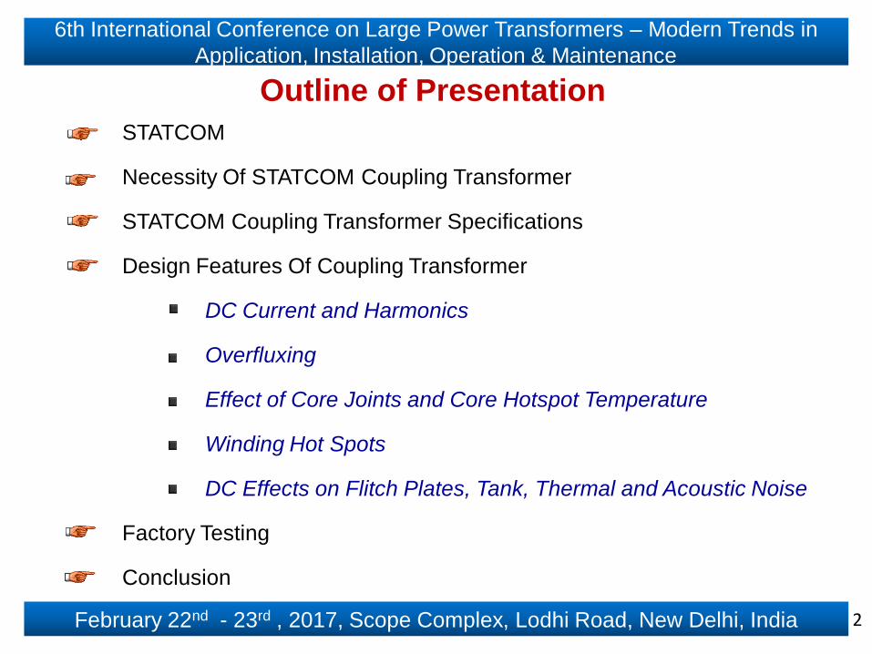
Outline of Presentation
STATCOM
Necessity Of STATCOM Coupling Transformer
STATCOM Coupling Transformer Specifications
Design Features Of Coupling Transformer
DC Current and Harmonics
Overfluxing
Effect of Core Joints and Core Hotspot Temperature
Winding Hot Spots
DC Effects on Flitch Plates, Tank, Thermal and Acoustic Noise
Factory Testing
Conclusion
February 22nd - 23rd , 2017, Scope Complex, Lodhi Road, New Delhi, India
6th International Conference on Large Power Transformers – Modern Trends in
Application, Installation, Operation & Maintenance
3
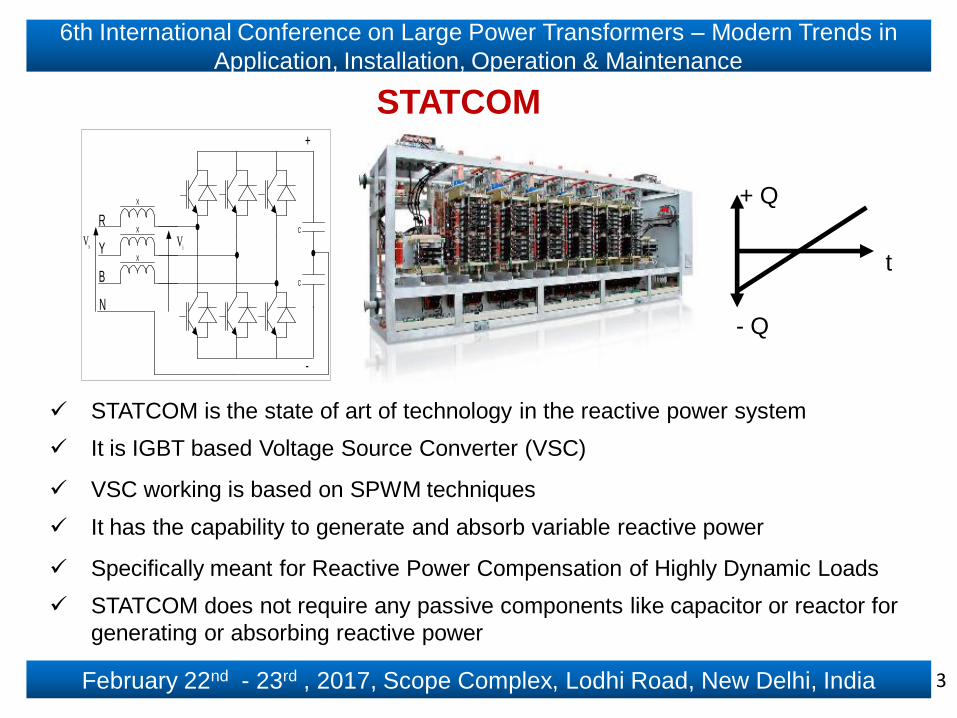
STATCOM
STATCOM is the state of art of technology in the reactive power system
It is IGBT based Voltage Source Converter (VSC)
VSC working is based on SPWM techniques
It has the capability to generate and absorb variable reactive power
Specifically meant for Reactive Power Compensation of Highly Dynamic Loads
STATCOM does not require any passive components like capacitor or reactor for
generating or absorbing reactive power
X
X
X
V s V
i
+
-
C
C R
Y
B
N
t
+ Q
- Q

February 22nd - 23rd , 2017, Scope Complex, Lodhi Road, New Delhi, India
6th International Conference on Large Power Transformers – Modern Trends in
Application, Installation, Operation & Maintenance
4
Mode-1: VSTAT < VS, STATCOM absorbs reactive power (Inductive)
Mode-2: VSTAT > VS, STATCOM injects reactive power (Capacitive)
Mode-3: VSTAT = VS, STATCOM does not work (Zero current)
Vs - Network Voltage
VSTAT - STATCOM Output Voltage
VSC - Voltage Source Converter
Single Line Diagram of STATCOM

February 22nd - 23rd , 2017, Scope Complex, Lodhi Road, New Delhi, India
6th International Conference on Large Power Transformers – Modern Trends in
Application, Installation, Operation & Maintenance
5
STATCOM - Features
Smooth and Ultra Dynamic Stepless Response
Continuously maintain unity Power Factor (P.F.) within its dynamic range
Dynamic range is in capacitive as well as inductive mode based on system demand
Reactive power is generated in IGBT based VSC and therefore does not require any
passive elements
No harmonics generation for adoption of SPWM technique
Integrated Active Harmonic Filter
Suited to a hybrid solution of STATCOM plus switched capacitors
Cheaper than SVC below 50 MVAr
Easy to install, less maintenance & Environment friendly
TSC
t
+ Q
- QSTATCOM

February 22nd - 23rd , 2017, Scope Complex, Lodhi Road, New Delhi, India
6th International Conference on Large Power Transformers – Modern Trends in
Application, Installation, Operation & Maintenance
6
Necessity Of STATCOM Coupling Transformer
Worldwide available STATCOM system voltage is less than 40 kV
STATCOM cannot be directly connected to the high voltage grids like 220kV, 400 kV, etc.,
Coupling Transformer is the intermediate device to connect STATCOM system and high
voltage grid with bidirectional power flow
The primary side of coupling transformer is connected to high voltage grid and secondary
side is connected to the STATCOM system
Coupling transformer does not require any tap changer since its voltage is controlled by
the STATCOM system
Coupling transformer step-up duty is too severe in STATCOM application and it must be
specifically designed to meet those requirements
February 22nd - 23rd , 2017, Scope Complex, Lodhi Road, New Delhi, India
6th International Conference on Large Power Transformers – Modern Trends in
Application, Installation, Operation & Maintenance
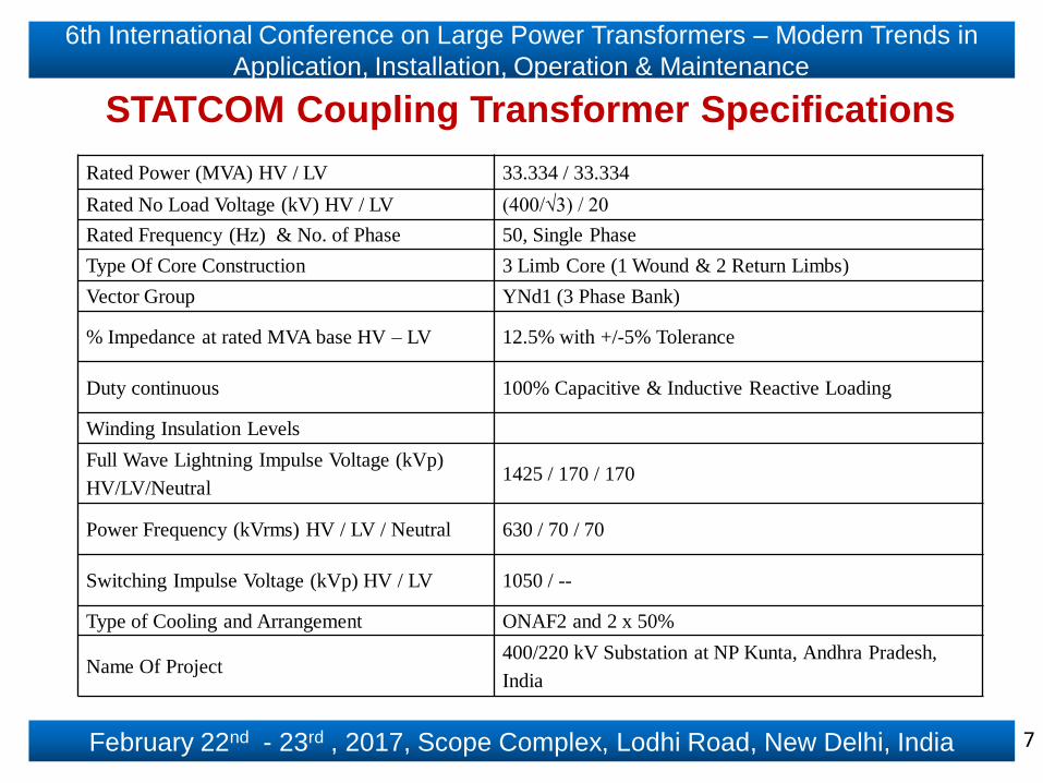
Rated Power (MVA) HV / LV 33.334 / 33.334
Rated No Load Voltage (kV) HV / LV (400/√3) / 20
Rated Frequency (Hz) & No. of Phase 50, Single Phase
Type Of Core Construction 3 Limb Core (1 Wound & 2 Return Limbs)
Vector Group YNd1 (3 Phase Bank)
% Impedance at rated MVA base HV – LV 12.5% with +/-5% Tolerance
Duty continuous 100% Capacitive & Inductive Reactive Loading
Winding Insulation Levels
Full Wave Lightning Impulse Voltage (kVp)
HV/LV/Neutral1425 / 170 / 170
Power Frequency (kVrms) HV / LV / Neutral 630 / 70 / 70
Switching Impulse Voltage (kVp) HV / LV 1050 / --
Type of Cooling and Arrangement ONAF2 and 2 x 50%
Name Of Project400/220 kV Substation at NP Kunta, Andhra Pradesh,
India
STATCOM Coupling Transformer Specifications
7

February 22nd - 23rd , 2017, Scope Complex, Lodhi Road, New Delhi, India
6th International Conference on Large Power Transformers – Modern Trends in
Application, Installation, Operation & Maintenance
Design Features Of Coupling Transformer
Coupling transformer must be designed and rated to carry 100% dynamic reactive power
loadings
Due to high frequency switching of IGBT and the DC capacitor voltage, STATCOM produces
DC current and harmonics in the secondary side of coupling transformer.
Certain level of direct current and harmonic currents consistent with the most onerous
operation of STATCOM should be withstood by the coupling transformer without loss of life
Presently very few manufacturers worldwide have made coupling transformers for 400 kV
system voltages
The main design features of the coupling transformer to be considered are
DC Current and Harmonics
Overfluxing
Effect of Core Joints and Core Hotspot Temperature
Winding Hot Spots
DC Effects on Flitch Plates, Tank, Thermal and Acoustic Noise
8

February 22nd - 23rd , 2017, Scope Complex, Lodhi Road, New Delhi, India
6th International Conference on Large Power Transformers – Modern Trends in
Application, Installation, Operation & Maintenance
DC Flux Density Shift in Transformer Core
Flux density shifts in the core caused by IDC
The magnitude of ФDC depends on the magnitude of the dc, No. of turns in the windings
carrying IDC & reluctance path of ФDC
The result is the ФDC adds to the ФAC in positive half-cycle and subtracts from the ФAC in
the negative half–cycle
9

February 22nd - 23rd , 2017, Scope Complex, Lodhi Road, New Delhi, India
6th International Conference on Large Power Transformers – Modern Trends in
Application, Installation, Operation & Maintenance
Half–Cycle Saturation of Core under Effect of DC Current
When the ФDC is max or transformer design “B” is high, the core peak “B” moves to the magnetic
core pre-saturation range in the positive half cycle, resulting in core saturation for a small part of a
cycle is called half-cycle or part-cycle saturation
For higher magnitudes of dc, the core provides a much higher reluctance to the DC Ampere-Turns
It results in a smaller incremental increase in the flux density shift and a higher peak magnetizing
current pulse
B – H characteristics of the coupling transformer core materials is inherently extremely non-linear
10

February 22nd - 23rd , 2017, Scope Complex, Lodhi Road, New Delhi, India
6th International Conference on Large Power Transformers – Modern Trends in
Application, Installation, Operation & Maintenance
DC Current and Harmonics
11

February 22nd - 23rd , 2017, Scope Complex, Lodhi Road, New Delhi, India
6th International Conference on Large Power Transformers – Modern Trends in
Application, Installation, Operation & Maintenance
Overfluxing
Voltage / Frequency ratio is called overfluxing factor
V/F ratio is generally constant, if “V” increases above nominal & “F” decreases
below nominal, core reach under saturation
Designing of minimum flux density for coupling transformer
Incremental flux density due to DC current
Frequency variation
Coupling transformer flux density variation due to STATCOM system
Capacitive loading, leading to increase in flux density in the core
12

February 22nd - 23rd , 2017, Scope Complex, Lodhi Road, New Delhi, India
6th International Conference on Large Power Transformers – Modern Trends in
Application, Installation, Operation & Maintenance
Effect of Core Joints and Core Hotspot Temperature
Mitred joint has a greater reluctance than a step-lap joint
Core magnetic material & core joint type have some influence on core saturation characteristics. However
this influence is small & depends on the core type & the operating flux density in the core
Typical temperature distribution in the core considering the effect of dc and harmonics of the STATCOM
13

February 22nd - 23rd , 2017, Scope Complex, Lodhi Road, New Delhi, India
6th International Conference on Large Power Transformers – Modern Trends in
Application, Installation, Operation & Maintenance
Winding Hot Spots
Winding hot spots are determined with the help of eddy loss
distribution which is governed by leakage field plot
The flux lines are predominantly axial in the central part
At the winding ends, due to fringing flux, the flux lines tend to
bend radially & there will be a radial component of eddies in
addition to axial eddies
Due to natural convection, temperature at top part will be higher
F. O probes are located within the LV & HV windings, on
transformer core and oil
The probes are to be monitored throughout testing process and
services
14

February 22nd - 23rd , 2017, Scope Complex, Lodhi Road, New Delhi, India
6th International Conference on Large Power Transformers – Modern Trends in
Application, Installation, Operation & Maintenance
DC Effects on Flitch Plates, Tank, Thermal and Acoustic Noise
Part-cycle of core saturation operating region as the result of dc
bias will produce greater levels of acoustical noise & tank
vibrations
Noise can be reduced by lowering “B” & by other means
IDC increases, the magnetic “B” in the tie–plates increases linearly until it reaches the
magnetic saturation level of the tie–plate material
To reduce tank stray losses, CRGO magnetic shunts are provided on the shorter side of HV
& LV windings of the tank
The height of CRGO magnetic shunts should be higher than the height of windings
Higher eddy & circulating current losses in the windings & the structural parts of the coupling
transformer; increasing their temperatures, which will require extra cooling
15

February 22nd - 23rd , 2017, Scope Complex, Lodhi Road, New Delhi, India
6th International Conference on Large Power Transformers – Modern Trends in
Application, Installation, Operation & Maintenance
Factory Testing
16

February 22nd - 23rd , 2017, Scope Complex, Lodhi Road, New Delhi, India
6th International Conference on Large Power Transformers – Modern Trends in
Application, Installation, Operation & Maintenance
17
CONCLUSIONThis coupling transformer technology, development, design and manufacturing is
based on Make in India concept and sell them anywhere in the world
Coupling Transformer should be designed and withstand the behavior of STATCOM
as mentioned below
Dynamic reactive power variation from capacitive to inductive & vice versa
DC and harmonics generated by STATCOM
Incremental flux density due to dc current
Significant rise of losses and system voltage instability
Increased reactive power consumption
The rise of internal hotspots, increased noise levels and tank vibrations are the effects
of STATCOM on the coupling transformer
The successful design, manufacturing process, factory testing and installation of this
400 kV coupling transformer will establish a “future-proofing” milestone for technology
development in India in the field of high voltage equipments for DRPC applications
February 22nd - 23rd , 2017, Scope Complex, Lodhi Road, New Delhi, India
6th International Conference on Large Power Transformers – Modern Trends in
Application, Installation, Operation & Maintenance
REFERENCES
[1] Ramsis Girgis & Kiran Vedante: “Effect of GIC on Power Transformers and Power Systems”, Presented at the
IEEE T&D Conference, May 2012, Orlando, FL.
[2] P. Picher, L. Bolduc et al, “Study of the acceptable DC current limit in core-form Power Transformers”, IEEE
Transactions on Power Delivery, Vol. 12, No. 1, January 1997, Page 257-265.
[3] Ramsis Girgis & Chung-Duck KO, “Calculation Techniques And Results Of Effects Of GIC Currents as Applied
to Two Large Power Transformers”, IEEE Transactions on Power Delivery, Vol. 7, No. 2, April 1992, Page 699-
705.
[4] P.R. Price. “Geomagnetically induced current effects on transformers” (IEEE Transactions on Power Delivery,
vol. 17, 2002, p. 1002 – 1008).
[5] S.Jeevananthan, R. Nandhakumar and P. Dananjayan, “Inverted sine Carrier for fundamental fortification in
PWM Inverters and FPGA based Implementations”, Serbian Journal of electrical engineering, Vol.4, No.2,
November 2007, Page(s) 171-187.
[6] R. Nandhakumar & S.Jeevananthan, “Inverted Sine Carrier Pulse Width Modulation for Fundamental
Fortification in DC-AC Converters”, Power Electronics and Drive Systems, 2007, PEDS’2007, Seventh
International Conference (IEEE), Bangkok, Thailand, Page(s): 1028 – 1034.
[7] CIGRE Working Group B4.53 report, “Guidelines for the procurement and testing of STATCOMS”. CIGRE
Brochure No. 663, August 2016.
[8] WG 12.06 Large transformers “Final report of WG 06 of Study Committee 12 (Transformers)”. ELECTRA No.
82, May 1982, pp. 31 – 46.
18
February 22nd - 23rd , 2017, Scope Complex, Lodhi Road, New Delhi, India
6th International Conference on Large Power Transformers – Modern Trends in
Application, Installation, Operation & Maintenance
Thank you
19
February 22nd - 23rd , 2017, Scope Complex, Lodhi Road, New Delhi, India
6th International Conference on Large Power Transformers – Modern Trends in
Application, Installation, Operation & Maintenance
20
QUESTIONS ???


![Schedule 4 – Distribution Transformer · PDF fileSchedule 4 – Distribution Transformer ... l. Permissible flux density and over fluxing [IS 1180 (part 1): 1989] Revised Schedule](https://img.dokumen.tips/doc/110x75/5aa5d7577f8b9a185d8dd8ee/schedule-4-distribution-transformer-4-distribution-transformer-l-permissible.jpg)