Embed Size (px)
Citation preview
©Prof. Z. Q. Zhu
EUGM 2014
1
Investigation on Torque in PM Machines- with particular reference to frozen permeability
The University of Sheffield, UK
Prof. Z. Q. Zhu and Dr. W. Q. Chu
04-06-2014

EUGM 2014
©Prof. Z. Q. Zhu
One of the largest research groups in the world, specialising on permanent magnet machines and control systems (>100 personnel, including 6 full professors, 12 Academic staff, >60 PhD students, >20 RAs)
Host• Rolls-Royce University Technology Centre in ‘Advanced Electrical Machines & Drives’• Sheffield Siemens Wind Power Research Centre (S2WP)• Romax Technical Centre
Birthplace 3 university spin-off companies (MagTec, Magnomatics, Red Deer Technologies Group)
Strong industrial collaboration, particularly in automotive, wind power, aerospace, and domestic appliance sectors
Electrical Machines and Drives Research Group
Headed by Prof. Z.Q. Zhu, Fellow IEEE, Fellow IET
2
EUGM 2014
©Prof. Z. Q. Zhu
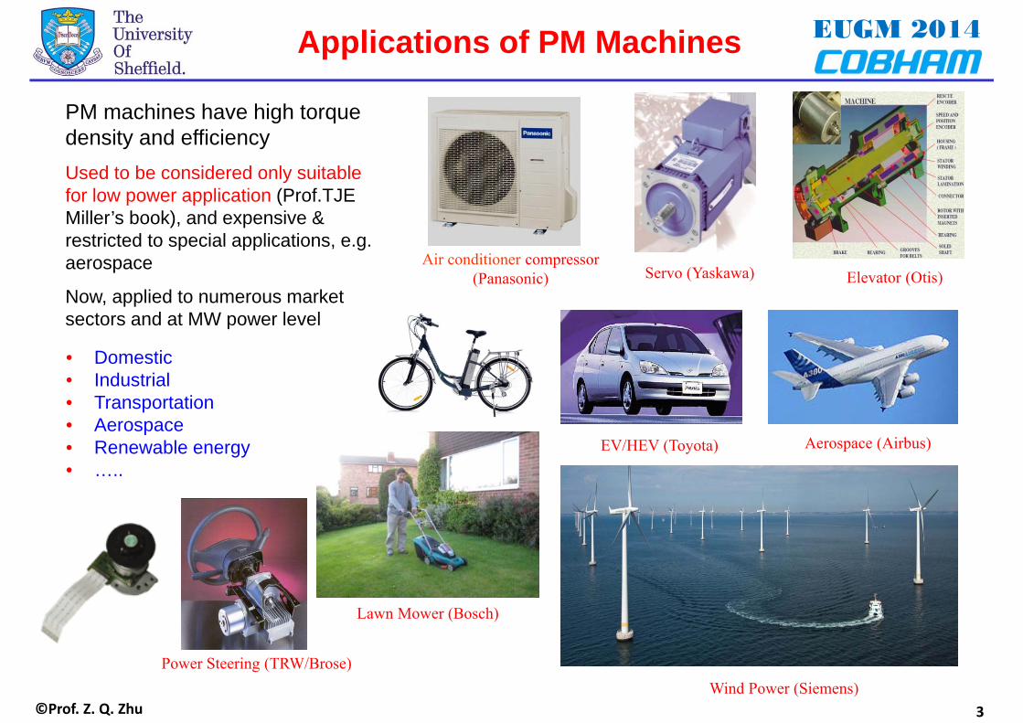
• Domestic• Industrial• Transportation• Aerospace • Renewable energy• …..
Applications of PM Machines
Air conditioner compressor(Panasonic)
Lawn Mower (Bosch)
Aerospace (Airbus)EV/HEV (Toyota)
PM machines have high torque density and efficiencyUsed to be considered only suitable for low power application (Prof.TJEMiller’s book), and expensive & restricted to special applications, e.g. aerospace
Now, applied to numerous market sectors and at MW power level
Elevator (Otis)Servo (Yaskawa)
Power Steering (TRW/Brose)Wind Power (Siemens)
3

©Prof. Z. Q. Zhu
EUGM 2014Contents
4
1. Introduction
2. Torque Calculation Methods
3. Torque Components Separation
Frozen permeability
Average torque: PM and reluctance torques
Torque ripple: On-load cogging torque etc
4. Influence of Skewing
5. Summary

©Prof. Z. Q. Zhu
EUGM 20141. Introduction
5
Torque
Average torque
Torque ripple
PM torque
Reluctance torque
Cogging torque
Maxwell stress tensor
Virtual work……
……
Finite element
Lump circuit model
Analytical
……
Calculation Analysis Improvement

EUGM 2014
©Prof. Z. Q. Zhu 6
• Maxwell stress tensor
• Virtual work method
Torque is calculated from an integral directly from the flux density components
ΔWin
Lossless machine
Δ Wm Δ Wout=Δ(Win-Wm )=Tout Δ θm
2. Torque Calculation Theories
µ0 : permeability of free space Lef : effective axial length r : radius of integration path Bn , Bt : normal and tangential flux density components
Torque is obtained from the energy conservation law.
Widely used in FE software, since flux density results are available
Not widely used, since differential operation is required/sometimes needs to be approximated
W'm : magnetic co-energy Wm : stored magnetic energy in the machine Win , Tin : input energy and corresponding torqueθm : rotor position in mechanical angle

EUGM 2014
©Prof. Z. Q. Zhu 7
• Calculation of magnetic energy
2. Torque Calculation Theories
PM (demagnetization curve)
wiron=∫HdB
wiron
Air
• Calculation of input torque (or power)
Iron (B-H curve)
Br : remanence flux densities. Bp : parallel flux densities.Bt : tangential flux densities.µrp, µrt: relative recoil permeability in parallel and tangential directions
Only valid for average torque calculation, not for torque ripple
PM
Iron

EUGM 2014
©Prof. Z. Q. Zhu 8
• Torque equations
2. Torque Calculation Theories
Based on abcia, ib, and ic : 3 phase currentsua, ub, and uc : 3 phase voltagesΩ : mechanical angular speed
Based on dq0
General form (mathematical mapping from abc torque equation by dq0 transformation)
Classical form (or simplified form) is based on assumptions: The windings are sinusoidally distributed around the stator periphery, giving rise to
a sinusoidal induced voltage and sinusoidal variation of self- and mutual inductance with rotor position.
The magnetic circuit is linear.
Hence, ψd and ψq are constant. ψd/dθ=0 and ψq/dθ =0.

EUGM 2014
©Prof. Z. Q. Zhu 9
• Numerical results
2. Torque Calculation Theories
T(dq0_g) and T(abc) are identical for torque calculation T(dq0_c) is simple but only able to predict the average torque To predict the torque ripple, it must use T(abc) or T(dq0_g)
• Examples
• Summary
If
Then
6-pole/18-slot inset SPM
0
1
2
3
4
5
0 30 60 90 120
Torq
ue (N
m)
Rotor position (degree)
T(abc) T(dq0_g) T(dq0_c)-1.2
-1.0
-0.8
-0.6
-0.4
-0.2
0.0
0 30 60 90 120
Torq
ue (N
m)
Rotor position (degree)
T(abc) T(dq0_g) T(dq0_c)
Inset SPM with Ia=4A and β=-30˚ Inset SPM with Ia=4A and β=-30˚ (no PM, current only)
EUGM 2014
©Prof. Z. Q. Zhu
-2
-1
0
1
2
3
4
5
0 30 60 90 120
Torq
ue (N
m)
Rotor position (degree)
TmwTvir=Tin-d(Wm)/dθmTind(-Wm)/dθm-0.6
-0.4
-0.2
0
0.2
0.4
0.6
0 30 60 90 120
Torq
ue (N
m)
Rotor position (degree)
TmwTvir=Tin-d(Wm)/dθmd(-Wm)/dθmTin
10
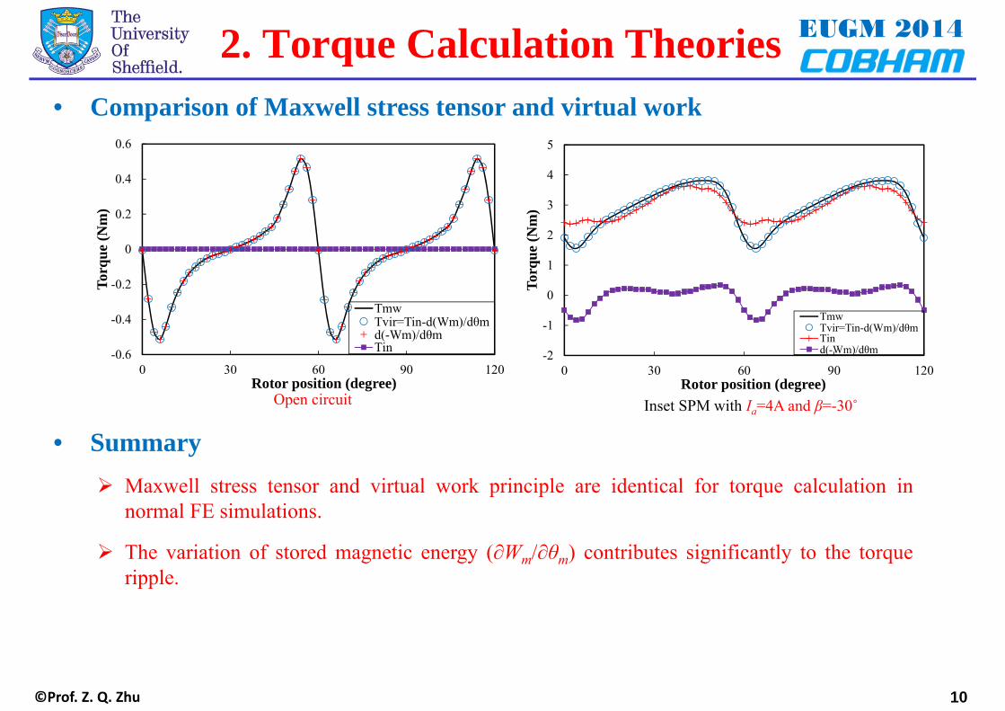
• Comparison of Maxwell stress tensor and virtual work
2. Torque Calculation Theories
Open circuit Inset SPM with Ia=4A and β=-30˚
Maxwell stress tensor and virtual work principle are identical for torque calculation innormal FE simulations.
The variation of stored magnetic energy (∂Wm/∂θm) contributes significantly to the torqueripple.
• Summary

EUGM 2014
©Prof. Z. Q. Zhu 11
• Purposes
• Principle
To separate the on-load PM and armature field when considering the saturation and cross-coupling
To separate the on-load torque components, both average and ripples
3. Frozen Permeability
Normal conditions (without using FP)
Ball = B(FP, PM) + Bi(FP, i)
µall < µPM
HPM PM only (B) BPM
Current only (C) Hi Bi
Current and PM (A) Hall = HPM + Hi Ball
Due to nonlinearity µall < µi Ball < BPM + Bi
Cannot decompose the on-load PM and armature field components
Using FPCurrent and PM (A) Hall = HPM + Hi Ball and µall
µall and PM only (D) HPM B(FP, PM)µall and current only (E) Hi B(FP, i)
All based on µall
On-load PM and armature field components can be decomposedH (A/m)
B (T)
HallHPMHi
Ball
B(FP, PM)
B(FP,i)
µallµPMµi
BPMBi
AB
C
E
D

EUGM 2014
©Prof. Z. Q. Zhu 12
• Procedures
Non-linear FE with all excitations(PM + current)
Save and freeze the permeability (every element and step)
Linear FE with single excitation(either PM or current)
3. Frozen Permeability

EUGM 2014
©Prof. Z. Q. Zhu 13
Field distribution
• All field quantities agree well.• Field distribution on load is asymmetric about d-axis, which is not a problem for field
calculation, but, as will be shown later, is a problem for torque calculation based on FP
Full load permeability
On-load PM field
Radial airgap flux density
Tangential airgap flux density
D-axis flux linkage
Q-axis flux linkage
Flux density distribution Flux linkage
3. Frozen Permeability• FE results
-1.5
-1.0
-0.5
0.0
0.5
1.0
1.5
-180 -120 -60 0 60 120 180R
adia
l flu
x de
nsity
(T)
Angle (degree)
Whole(FP,PM)+(FP,i)(FP,PM)(FP,i)
-0.5-0.4-0.3-0.2-0.10.00.10.20.30.40.5
-180 -120 -60 0 60 120 180
Tang
entia
l flu
x de
nsity
(T)
Angle (degree)
Whole(FP,PM)+(FP,i)(FP,PM)(FP,i)
-0.05
0.00
0.05
0.10
0.15
0.20
0.25
0.30
0 30 60 90 120
D-a
xis f
lux
linka
ge (W
b)
Rotor position (degree)
Whole(FP,PM)+(FP,i)(FP,PM)(FP,i)
-0.05
0.00
0.05
0.10
0.15
0.20
0.25
0.30
0 30 60 90 120
Q-a
xis f
lux
linka
ge (W
b)
Rotor position (degree)
Whole(FP,PM)+(FP,i)(FP,PM)(FP,i)

EUGM 2014
©Prof. Z. Q. Zhu 14
• Two different ways of torque separation
Maxwell stress tensor: FP based flux density results and direct torque output of FE
Virtual work principle: indirect results based on FP obtained flux linkage, energy and currents
3.0 Torque Separation
Whole model(PM+current)
Frozen permeability (PM only)
Tmw
ψd , ψqTvir
Frozen permeability (current only)
Tmw(FP, PM)
ψd (PM), ψq(PM)Tvir(FP, PM)
Tmw(FP, i)
ψd (i),ψq(i)Tvir(FP, i)
Maxwell stress tensor
Virtual work
Maxwell stress tensor
Virtual work
Maxwell stress tensor
Virtual work

EUGM 2014
©Prof. Z. Q. Zhu 15
• Two different ways of average torque separation
3.1 Average Torque Separation
Maxwell stress tensor Virtual workTotal torque Tmw Tvir
Reluctance torque Tmw(FP,i) Tvir(FP,i)PM torque Tmw-Tmw(FP,i) Tvir(PM) or Tvir-Tvir(FP,i)On-load cogging Tmw(FP,PM) Tvir(FP,PM)
Maxwell stress tensor:
Direct results based on flux density results
Virtual work principle:
Indirect results based on flux linkage, energy and currents
** Tvir(rel), Tvir(FP,i), Tvir(PM),Tvir(FP,PM) are based on classic dq0torque equation for average torqueestimation
All field components and flux linkages are FP results

EUGM 2014
©Prof. Z. Q. Zhu
-1.0-0.8-0.6-0.4-0.20.00.20.40.60.81.0
0 30 60 90 120
Torq
ue (N
m)
Rotor position (degree)
Tmw(FP,PM)
Tvir(FP,PM))
-1.2
-1.0
-0.8
-0.6
-0.4
-0.2
0.0
0 30 60 90 120
Torq
ue (N
m)
Rotor position (degree)
Tmw(FP,i)
Tvir(FP,i)
16
• Problems
• Numerical results of inset SPM machine when Ia=4.0A, β=-30˚
Average Tmw(FP,PM) (cogging torque) is not zero
Average torque components from virtual work and Maxwell stress tensor are different but the resultant average torque is the same
Torque components cannot be obtained by FE directly based on Maxwell stress tensor.
FP + PM (cogging torque)
3.1 Average Torque Separation
FP + i
-2
-1
0
1
2
3
4
5
6
-90 -60 -30 0 30 60 90
Torq
ue (N
m)
Current phase advance angle (degree)
TvirTmwTvir(PM)Tmw(PM)Tvir(FP,i)Tmw(FP,i)
EUGM 2014
©Prof. Z. Q. Zhu 17
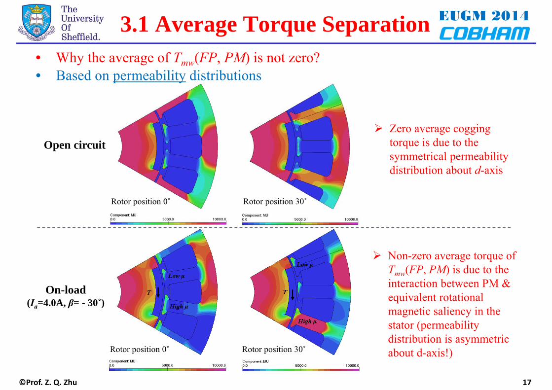
• Why the average of Tmw(FP, PM) is not zero?
Rotor position 0˚ Rotor position 30˚
Non-zero average torque of Tmw(FP, PM) is due to the interaction between PM & equivalent rotational magnetic saliency in the stator (permeability distribution is asymmetric about d-axis!)
3.1 Average Torque Separation
• Based on permeability distributions
Rotor position 0˚ Rotor position 30˚
Open circuit
On-load(Ia=4.0A, β= - 30˚)
Zero average cogging torque is due to the symmetrical permeability distribution about d-axis
EUGM 2014
©Prof. Z. Q. Zhu
-1.5
-1.0
-0.5
0.0
0.5
1.0
1.5
-90 -60 -30 0 30 60 90
Torq
ue (N
m)
Current phase advance angle (degree)
Tmw(FP,i)Tvir(FP,i)
-1.0
-0.8
-0.6
-0.4
-0.2
0.0
0.2
0.4
0.6
0.8
0 30 60 90 120
T qou
t(FP,
PM)
(Nm
)
Rotor position (degree)
Open circuit
Loaded
18
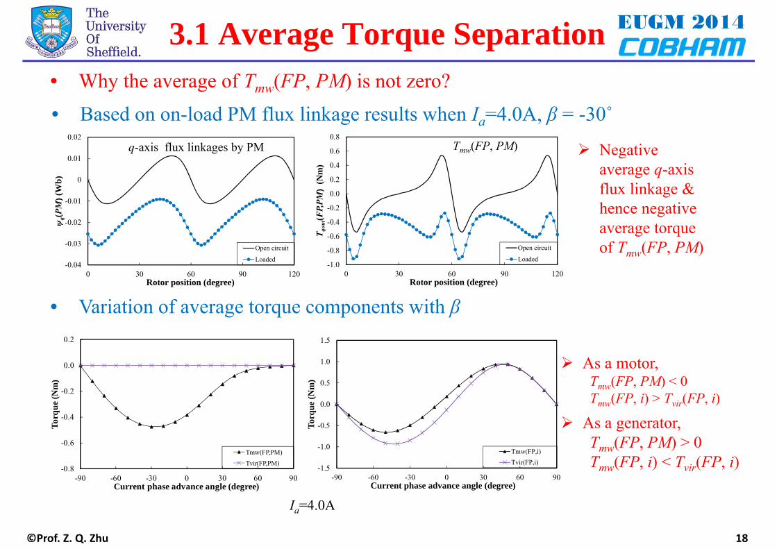
• Why the average of Tmw(FP, PM) is not zero?• Based on on-load PM flux linkage results when Ia=4.0A, β = -30˚
As a motor,Tmw(FP, PM) < 0Tmw(FP, i) > Tvir(FP, i)
As a generator,Tmw(FP, PM) > 0Tmw(FP, i) < Tvir(FP, i)
Negative average q-axis flux linkage & hence negative average torque of Tmw(FP, PM)
-0.04
-0.03
-0.02
-0.01
0
0.01
0.02
0 30 60 90 120
ψq(
PM) (
Wb)
Rotor position (degree)
Open circuit
Loaded
3.1 Average Torque Separation
-0.8
-0.6
-0.4
-0.2
0.0
0.2
-90 -60 -30 0 30 60 90
Torq
ue (N
m)
Current phase advance angle (degree)
Tmw(FP,PM)Tvir(FP,PM)
• Variation of average torque components with β
q-axis flux linkages by PM Tmw(FP, PM)
Ia=4.0A

EUGM 2014
©Prof. Z. Q. Zhu 19
• Conclusions on average torque separation
• Numerical results
Average torque components should be separated based on virtual work principle
PM torque:
Reluctance torque:
-2.0
-1.0
0.0
1.0
2.0
3.0
4.0
5.0
6.0
-40 -30 -20 -10 0 10 20 30 40
Torq
ue (N
m)
Advance angle (degree)
TmwTvirTvir(FP,PM)+Tvir(Fp,i)Tvir(FP,PM)=1.5p[ψd(PM)*Iq-ψq(PM)*Id]Tvir(FP,i)=1.5p[ψd(i)*Iq-ψq(i)*Id]
-1.5
-1.0
-0.5
0.0
0.5
1.0
1.5
-40 -30 -20 -10 0 10 20 30 40
Torq
ue (N
m)
Advance angle (degree)
Tr=Tmw-1.5p[ψd(PM)*Iq-ψq(PM)*Id]
Tvir(FP,i)=1.5p[ψd(i)*Iq-ψq(i)*Id]Tmw(FP,i)
3.1 Average Torque Separation
Resultant total torques from Maxwell stress and virtual work are the same
Torque components obtained from Maxwell stress is incorrect

EUGM 2014
©Prof. Z. Q. Zhu
3.2 Torque Ripple Separation
20
• Problem
• Incorrect magnetic energy calculation in conventional FP method
Average Tmw(FP, PM) ≠0. Hence, it cannot be the on-load cogging torque
Using the magnetic energy variation instead of Tmw(FP, PM) :
Magnetic energy calculation in the iron with frozen permeability
It is due to that it is the linear FP FE solution
Procedure
Non-linear FE with all excitations(PM + current)
Save and freeze the permeability (every element and step)
Linear FE with single excitation(either PM or current)
Incorrect energy area in the iron

EUGM 2014
©Prof. Z. Q. Zhu 21
• Solution:Using nonlinear FP FE with iteration step =1 for energy calculation, instead of linear FP FE
(available in OPERA)
Resultant full load (PM+i)
Non-linear FE with , iteration step=1 (either PM or current)
Non-linear FE with all excitations(PM + current)
Save and freeze the permeability (every element and step)
Non-linear FE with all excitations(PM + current)
Save and freeze the permeability (every element and step)
Linear FE with single excitation(either PM or current)
Linear FP+PM Nonlinear FP+PM(iteration step=1)
Same permeability Same field
Different permeability
Different field
3.2 Torque Ripple Separation
See next page

EUGM 2014
©Prof. Z. Q. Zhu
0.00
0.05
0.10
0.15
0.20
0.25
0 30 60 90 120
Ene
rgy
(W)
Rotor position (degree)
Wiron(FP,PM) ∫HdB
Wiron(FP,PM) HB/2
0.00
0.05
0.10
0.15
0.20
0.25
0 30 60 90 120
Ene
rgy
(W)
Rotor position (degree)
Wiron'(FP,PM) ∫HdB
Wiron'(FP,PM) HB/2
22
• Magnetic energy calculation in the ironNonlinear FP (iteration step=1)
Using nonlinear FP method (available using OPERA) can obtain the magnetic energy in the iron correctly
3.2 Torque Ripple Separation
∫HdB=HB/2 ∫HdB<HB/2
Linear FP
EUGM 2014
©Prof. Z. Q. Zhu 23
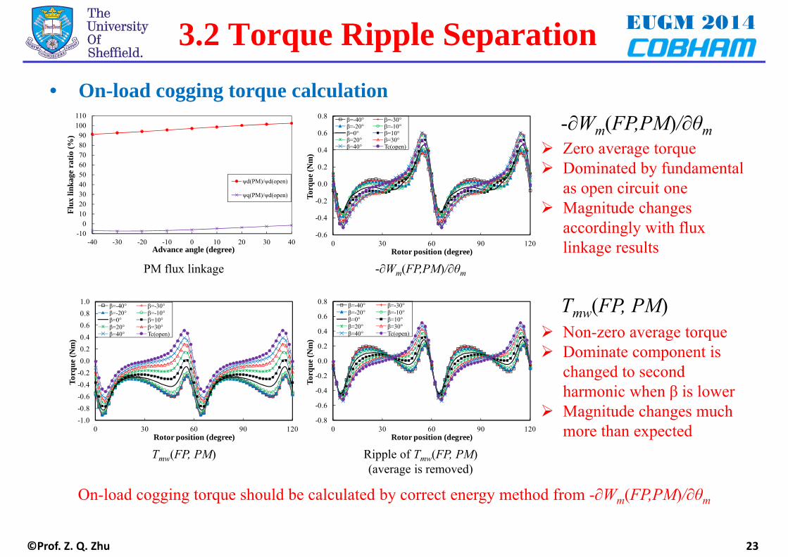
• On-load cogging torque calculation-∂Wm(FP,PM)/∂θm
-0.6
-0.4
-0.2
0.0
0.2
0.4
0.6
0.8
0 30 60 90 120
Torq
ue (N
m)
Rotor position (degree)
β=-40° β=-30°β=-20° β=-10°β=0° β=10°β=20° β=30°β=40° Tc(open)
-0.8
-0.6
-0.4
-0.2
0.0
0.2
0.4
0.6
0.8
0 30 60 90 120
Torq
ue (N
m)
Rotor position (degree)
β=-40° β=-30°β=-20° β=-10°β=0° β=10°β=20° β=30°β=40° Tc(open)
-1.0-0.8-0.6-0.4-0.20.00.20.40.60.81.0
0 30 60 90 120
Torq
ue (N
m)
Rotor position (degree)
β=-40° β=-30°β=-20° β=-10°β=0° β=10°β=20° β=30°β=40° Tc(open)
On-load cogging torque should be calculated by correct energy method from -∂Wm(FP,PM)/∂θm
PM flux linkage -∂Wm(FP,PM)/∂θm
Tmw(FP, PM) Ripple of Tmw(FP, PM) (average is removed)
Tmw(FP, PM)
Zero average torque Dominated by fundamental
as open circuit one Magnitude changes
accordingly with flux linkage results
Non-zero average torque Dominate component is
changed to second harmonic when β is lower
Magnitude changes much more than expected
3.2 Torque Ripple Separation
-100
102030405060708090
100110
-40 -30 -20 -10 0 10 20 30 40
Flux
link
age
ratio
(%)
Advance angle (degree)
ψd(PM)/ψd(open)
ψq(PM)/ψd(open)

©Prof. Z. Q. Zhu
EUGM 20143. Summary
24
• The results from Maxwell stress tensor and virtual work principle areidentical for torque calculation in normal FE simulations.
• To predict the torque ripple, it must use T(abc) or T(dq0_g), whilstT(dq0_c) is simple but only able to predict the average torque.
• Non-zero average torque of Tmw(FP, PM) (non-zero on-load coggingtorque obtained by Maxwell stress) is due to the interaction between PMand equivalent rotational magnetic saliency in the stator.
• On-load cogging torque can be predicted by -∂Wm(FP,PM)/∂θm combinedwith nonlinear FP method.
• PM and reluctance torques should be separated based on the combinationof virtual work principle and frozen permeability, using correct energycalculation.

EUGM 2014
©Prof. Z. Q. Zhu 25
• Skewing is one of most widely used method to reduce the torque ripple
4. Influence of Skewing
• Skewing angle (θsk) is usually chosen to be equal to one torque ripple period
• For 3-phase PM machines, both the on-load torque ripple and cogging torque areexpected to be eliminated when θsk is 60° electrical
• When the end effect is negligible, instead of complicated and time consuming 3Dmodelling, multi-slice model can be used
• OPERA can create all the slices automatically and all the slices are solvedsimultaneously (Their torque waveforms are different. If the result for different slice isobtained simply by shifting, the resultant torque with skewing will be incorrect no matterwhether the machine is saturated or unsaturated, as will be shown later).
30º elec.
60º elec.
Axial
S
S
60º elec.
Axial
……
S
S
60º/N elec.N-slice
or N-steps
2-slice or
2-steps

EUGM 2014
©Prof. Z. Q. Zhu 26
• 20-slice skewing with θsk = 60° using OPERA.
4. Influence of Skewing
• Two machines (with/without shaping), three operations (open circuit, 60A and 120A).
M1
N-slice or
N-steps
-3500
-3000
-2500
-2000
-1500
-1000
-500
0
500
0 30 60 90 120 150 180
Torq
ue (N
m)
Rotor position (degree)
Without skewingWith skewing
Open circuit
Half load
Full load
0.00
0.01
0.02
0.03
1 2 3 4
Torq
ue r
ippl
e (p
.u.)
Harmonics
Open circuitOpen circuit + skewingHalf loadHalf load + skewingFull loadFull load + skewing
-3500
-3000
-2500
-2000
-1500
-1000
-500
0
500
0 30 60 90 120 150 180
Torq
ue (N
m)
Rotor position (degree)
Without skewingWith skewing
Open circuit
Half load
Full load0.00
0.02
0.04
0.06
0.08
0.10
0.12
1 2 3 4
Torq
ue r
ippl
e (p
.u.)
Harmonics
Open circuitOpen circuit + skewingHalf loadHalf load + skewingFull loadFull load + skewing
M2
Cogging torque: eliminated Half load torque ripple: reduced but not eliminated. Full load torque ripple: reduced for M2 but increased for M1.

EUGM 2014
©Prof. Z. Q. Zhu 27
4. Influence of Skewing• Effects of skewing
Skewing Equations2-step
3-step
ContinuousT2=T(β= β0 +15º,θ0= -15º)
T1=T(β= β0 -15º,θ0= 15º)
In each slice, the current amplitude is the same but the equivalent phase angle is different,either advanced or retarded, compared to the middle slice (or emf)
This axial variation of equivalent advanced or retarded current phase angle causes (1) differentEM torque ripples in different slices, as well as (2) axial variation of magnetic saturation,which make the skewing less effective or even failed
This is true, no matter whether the machine is saturated [due to (1) and (2)] or unsaturated [dueto (1) only]
It is also true when the stator is skewed instead of rotor
• Overall torque equation considering two effects
• Further explanations are based on 2-slice skewing and θsk=60º.

EUGM 2014
©Prof. Z. Q. Zhu 28
4. Influence of Skewing• Open circuit of M1
-15
-10
-5
0
5
10
15
0 30 60 90 120 150 180
Torq
ue (N
m)
Rotor position (degree)
T1 (θo=15) T2 (θo= -15) Tsk
No EM torque. T1 and T2 for Segments 1 and 2 have the same waveform
After skewing, T1 and T2 are anti-phase in terms of the fundamental torque ripple
The fundamental torque ripple are eliminated in Tsk while all the other harmonics remain
Mathematically, it can be concluded that only kN order cogging torque harmonics remain after N-step skewing. By using continuous skewing, the cogging torque can be eliminated.
The mechanism of skewing for reducing the torque ripples is the cancellation of harmonics based on the waveform shifting, which is due to the geometric shifting
In order to eliminate the torque ripple by skewing,
All slices have the same torque waveform
The phase difference between the torque components of different slices is only due to the geometric shifting introduced by skewing
EUGM 2014
©Prof. Z. Q. Zhu 29
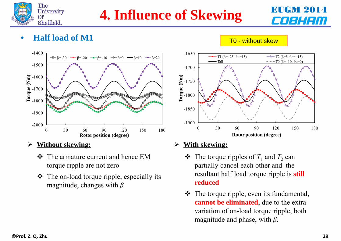
4. Influence of Skewing• Half load of M1
Without skewing:
-2000
-1900
-1800
-1700
-1600
-1500
-1400
0 30 60 90 120 150 180
Torq
ue (N
m)
Rotor position (degree)
β= -30 β= -20 β= -10 β=0 β=10 β=20
-1900
-1850
-1800
-1750
-1700
-1650
0 30 60 90 120 150 180
Torq
ue (N
m)
Rotor position (degree)
T1 (β= -25, θo=15) T2 (β=5, θo= -15)Tall T0 (β= -10, θo=0)
With skewing:
The armature current and hence EM torque ripple are not zero
The on-load torque ripple, especially its magnitude, changes with β
The torque ripples of T1 and T2 can partially cancel each other and the resultant half load torque ripple is still reduced
The torque ripple, even its fundamental, cannot be eliminated, due to the extra variation of on-load torque ripple, both magnitude and phase, with β.
T0 - without skew

EUGM 2014
©Prof. Z. Q. Zhu 30
4. Influence of Skewing• Full load of M1
Without skewing: With skewing:
The magnetic saturation due to armature reaction and EM torque ripple are much higher.
The on-load torque ripple changes significantly with β.
The torque ripples are almost anti-phasewhen β changes by 30º.
The torque ripples of T1 and T2 are not anti-phase but almost in-phase.
The resultant full load torque ripple is not eliminated but increased, since the ripple of T2 is much higher than T0.
-3000
-2900
-2800
-2700
-2600
-2500
-2400
-2300
-2200
0 30 60 90 120 150 180
Torq
ue (N
m)
Rotor position (degree)
β= -30 β= -20 β= -10 β=0 β=10 β=20 -2900
-2850
-2800
-2750
-2700
-2650
-2600
0 30 60 90 120 150 180
Torq
ue (N
m)
Rotor position (degree)
T1 (β= -25, θo=15) T2 (β=5, θo= -15)Tall T0 (β= -10, θo=0)
T0 - without skew

EUGM 2014
©Prof. Z. Q. Zhu 31
4. Influence of Skewing• Full load of M2
Without skewing: With skewing:
The phase of full load torque ripple without skewing does vary with current phase advance angle but only slightly, due to high cogging torque
The full load torque ripple is reduced but not eliminated, due to the extra torque ripple variation with β.
-3500
-3300
-3100
-2900
-2700
-2500
-2300
-2100
0 30 60 90 120 150 180
Torq
ue (N
m)
Rotor position (degree)
β= -30 β= -20 β= -10 β=0 β=10 β=20
-3400
-3200
-3000
-2800
-2600
-2400
0 30 60 90 120 150 180
Torq
ue (N
m)
Rotor position (degree)
T1 (β= -25, θo=15) T2 (β=5, θo= -15)Tsk T0 (β= -10, θo=0)
T0 - without skew

EUGM 2014
©Prof. Z. Q. Zhu
0.00
0.02
0.04
0.06
0.08
0.10
0.12
1 2 3 4
Mag
nitu
de (p
.u.)
Harmonics
β= -30β= -20β= -10β=0β=10β=20
-0.06
-0.04
-0.02
0
0.02
0.04
0.06
1 2 3 4
Mag
nitu
de (p
.u.)
Harmonics
β= -30β= -20β= -10β=0β=10β=20
0.00
0.02
0.04
0.06
0.08
0.10
0.12
1 2 3 4
Torq
ue r
ippl
e (p
.u.)
Harmonics
Without skewingSkewed
0.00
0.02
0.04
0.06
0.08
0.10
0.12
1 2 3 4
Mag
nitu
de (p
.u.)
Harmonics
Without skewingSkewed
32
• Comparison between M1 and M2 at full load
4. Influence of Skewing
M1 M2
M1 M2
Without skewing:The fundamental torque ripples of M1 and M2 change with β by almost the same amount (in EM torque).e.g. from -30º to 20º, the changes are about 0.067 p.u.
With skewing (β=-10º):The resultant fundamental torque ripples are almost at the same level (full load+skewing = ~0.0249 p.u.)
The on-load torque ripple reduction in M2 is mainly due to reduction of its remarkable cogging torque.
The skewing still fails to eliminate the EM torque ripple at full load.
≈0.067p.u.
≈0.067p.u.
0.015 p.u.
≈0.0249 p.u.

EUGM 2014
©Prof. Z. Q. Zhu
-2900
-2850
-2800
-2750
-2700
-2650
-2600
0 30 60 90 120 150 180
Torq
ue (N
m)
Rotor position (degree)
without 2-step 3-step 4-step5-step 6-step continuous 0.00
0.01
0.02
0.03
0.04
0.05
1 2 3 4 5 6 7 8
P-p
torq
ue r
ippl
e (p
.u.)
Number of steps
Open circuitIa=60A, β= -10Ia=120A, β= -10
-15
-10
-5
0
5
10
15
0 30 60 90 120 150 180
Torq
ue (N
m)
Rotor position (degree)
without 2-step 3-step 4-step5-step 6-step continuous
-1900
-1850
-1800
-1750
-1700
0 30 60 90 120 150 180
Torq
ue (N
m)
Rotor position (degree)
without 2-step 3-step 4-step5-step 6-step continuous
33
• In order to ease the manufacturing and reduce the cost
4. Step Skewing
Open circuit
M2
Full load• 3-step skewing is the most promising alternative in low cost application.• Torque ripple only eliminated on open-circuit, but not on load, depending on load conditions.
• Based on M1 and θsk = 60°• Influence of number of steps
Half load
Torque ripple variation

EUGM 2014
©Prof. Z. Q. Zhu 34
4. Summary
• The effectiveness of skewing on the torque ripple reduction largely depends on the axial variation of torque ripple phase but less on the magnitude.
• Skewing one on-load torque ripple period, the cogging torque is eliminated. However, the EM and hence on-load torque ripple cannot be eliminated.
• After skewing, the EM torque ripple can be reduced if there is no saturation, but may be reduced or even increased if it is saturated depending on the electric loading.
• Skewing is effective in reducing the cogging torque. Hence, when the cogging torque is higher, the skewing is more effective on the on-load torque ripple reduction. In contrast, when the EM torque ripple is high, it is less effective.
• The on-load torque ripple can be even increased by skewing especially when the cogging torque is low and the EM torque ripple is high.
EUGM 2014
©Prof. Z. Q. Zhu 35
5. Conclusions
• Torque components can be separated based on the combination of virtualwork principle and frozen permeability using correct energy calculation.
• On-load cogging torque cannot be calculated by Tmw(FP, PM) but can bepredicted by -∂Wm(FP,PM)/∂θm combined with nonlinear FP method.
• Skewing is effective in reducing the cogging torque.• After skewing, the on-load torque ripple is not necessary reduced.
• The on-load torque ripple may be even increased by skewing.