Embed Size (px)
Citation preview

Terahertz Science and Technology, ISSN 1941-7411 Vol.8, No.1, March 2015
1
Invited Paper
Development of high power gyrotron and related technologies
Keishi Sakamoto *, Yasuhisa Oda, Ryosuke Ikeda, Takayuki Kobayashi, Ken Kajiwara, Koji Takahashi and Shinichi
Moriyama
Japan Atomic Energy Agency, 801-1 Mukoyama, Naka, Ibaraki, Japan 311-0193 * Email: [email protected]
(Received March 25, 2015)
Abstract: The research and development activities of high-power gyrotrons in JAEA for the use in nuclear fusion
applications are reported. ITER requires 170 GHz 1 MW gyrotrons which are currently under development. High
order modes of a cylindrical resonator to serve as oscillation mode candidates for 1 MW/ 170 GHz CW operation are
studied. TE31,8 mode has shown the best performance operation, e.g., 1 MW/ 800 s/ 55% and 0.8 MW/1 hr/57%. Even
higher modes are attempted to increase power. At the present stage, in TE31,11 mode, 1.24 MW/2s and 0.5 MW/1000 s
have been achieved. This 170 GHz/TE31,11 mode has excellent characteristics for multi-frequency operation. By
controlling resonant magnetic field and pitch factor of the electron beam, Gaussian power output was demonstrated
at 203 GHz, 170 GHz, 137 GHz and 104 GHz. An anode control method was studied as a possible advantage
operation scenario. A 5 kHz 1 MW full-power modulation for the plasma instability suppression was successfully
demonstrated at 170 GHz by the fast of-off control of the anode voltage. A fast frequency switching of the gyrotron
was studied for the power deposition profile control in the tokamak plasma, and the switching between 170 GHz and
167 GHz was proved with 3.5 s using the super-conducting sweeping coil. Furthermore, dual frequency 138 GHz/110
GHz gyrotron was developed for the application in the EC heating and current drive system of the JT-60SA tokamak.
Power outputs of 1 MW/100 s were demonstrated at both frequencies. High power experiments of the transmission
line and launcher were carried out using the gyrotron as a power source.
Keywords: High power gyrotron, Multi-frequency, Fast frequency switching, Power modulation
doi: 10.11906/TST.001-018.2015.03.01
1. Introduction
Gyrotrons are a high-power source of coherent microwaves which use mildly relativistic
magnetized electron beams and are based on the cyclotron-resonance maser effect. High-power

Terahertz Science and Technology, ISSN 1941-7411 Vol.8, No.1, March 2015
2
gyrotrons are used in electron cyclotron heating and current drives (EC H&CD) of the nuclear
fusion research in the field of magnetically confined plasma. Their frequencies are in the
so-called mm-wave range (28 GHz~170 GHz), and extensive research and development have
been conducted [1-16]. And an even higher frequency >200 GHz is proposed in the DEMO
reactor [17]. The EC waves are useful not only for H&CD but also for initiating plasmas and
active control of MHD instabilities [18-21]. In addition, mm-waves are attractive for fusion
reactors, because the mm-waves can be launched into the plasma with high power density
through a relatively small hole. Since the gyrotrons can be placed far from the reactor, therefore,
maintenance is easy and the system is expected to be highly reliable. The 1 MW 170 GHz
gyrotrons will be used in ITER [22-23]. Their configuration is shown in Fig.1. From the gyrotron
building where the twenty-four 1 MW gyrotrons are placed, the mm-wave power is transmitted to
the plasma by the 24-line evacuated corrugated waveguides. The length of the transmission line is
around 150 m. The power is injected into the toroidal plasma via two types of the launchers. One
is an equatorial port launcher, which has twenty-four mm-wave beam lines and is used for
heating and current drive. The other is an upper port launcher, which has eight mm-wave beam
lines. ITER has four upper port launchers. Both launchers have steering mirrors to control the
power deposition profile in the tokamak plasma. Each transmission line has a waveguide switch
for selecting the injection port. The 170 GHz gyrotrons require, 1 MW, quasi-CW power output
having 50% efficiency. Presently, Japan and Russia have demonstrated a gyrotron that satisfies
the ITER criteria.
Fig. 1 Schematic view of Electron cyclotron heating and current drive system of ITER with 170 GHz 1 MW gyrotron.
A height and weight of the gyrotron is ~3 m and 800 kg, respectively.

Terahertz Science and Technology, ISSN 1941-7411 Vol.8, No.1, March 2015
3
Modern high-power gyrotrons consist of an electron gun (magnetron injection gun: MIG),
beam tunnel, cavity (resonator), built-in mode converter, diamond window for power output and
a collector, and are inserted in a solenoid super-conducting magnet (SCM). The electron gun
emits an annular electron beam of 60 keV~90 keV. Each electron has a gyro-motion at the cavity
with a pitch factor of about 1.0~1.4. By adjusting the resonance magnetic field and the beam
position in the cavity, the oscillation of the objective mode is obtained. The power conversion
efficiency from the electron beam to the microwave is 30~40%. A part of the residual power of
the electron beam after the cavity interaction is recovered using a retarding potential between the
cavity and the collector (depressed collector configuration).
In JAEA, the first 170 GHz gyrotron aiming for 1 MW power output was fabricated in 1995.
The oscillation mode was TE31,8 mode, and 1 MW (1 ms) oscillation was demonstrated in 1996. A
diamond window was first installed in 1998. Pulse duration and output power increased by
improving the MIG, beam tunnel, the quasi-mode converter, stray radiation treatment, and a
1 MW, >50%, quasi-CW operation was demonstrated in 2006. After demonstrating the
ITER-relevant 1 MW 170 GHz gyrotron, higher power gyrotrons, multi-frequency gyrotrons and
advanced operation technologies continued to be developed.
The 110 GHz gyrotron were used in the EC system of the JT-60U tokamak in 1999, and
currently dual frequency gyrotrons for the JT-60SA tokamak are being developed.
EC technology such as high-power mm-wave transmission components [24-29] and power
supplies for advanced gyrotron operation are also being developed in parallel.
In this paper, development activities of advanced high-power gyrotrons are described. Sections
2 and 3 describe the design of the 1 MW 170 GHz gyrotrons as well as the multi-frequency
gyrotrons. The result of full-power modulation using an anode switch is shown in section 4.
Section 5 introduces the activities for applying the electron cyclotron heating and current-drive to
the ITER, while section 6 summarizes the paper.
2. High-power 1 MW 170 GHz gyrotrons
R&D of the 1 MW 170 GHz gyrotrons started with the TE31,8 oscillation mode in a cylindrical
open cavity. This mode was selected as the minimum mode number to generate 1 MW CW
oscillation at 170 GHz, i.e., the heat load on the inner surface of the cavity is suppressed to the
level of ~20 MW/m2. After ITER-relevant parameters were demonstrated [11], the oscillation
Terahertz Science and Technology, ISSN 1941-7411 Vol.8, No.1, March 2015
4
mode number was increased to relax the Ohmic heat load on the inner wall of the cavity. The
tested modes were TE31,9, TE31,11 and TE31,12. As the frequency (f=170 GHz) and the m-number of
the TEm,n mode are the same (m=31), the beam position rb (=rcavm-1,1/m-1,n ~ cm-1,1/(2f)) in the
cavity is the same, and the beam trajectory is the same among these modes. Therefore,
components having identical designs such as the MIG, beam tunnel, collector, and 7 T solenoid
coil are available with the exception of the cavity and the mode converter/mirrors. Here, rcav :a
cavity radius, m,n : n-th root of m-th Bessel function dJm(x)/dx=0, f: frequency, c: light velocity.
2-1 Gyrotron setup and quasi- CW highly efficient oscillation
A picture of a 170 GHz gyrotron is shown in Fig.1 and is approximately ~3 m in height and
weights ~800 kg including the X-ray shield around the collector. A schematic view is shown in
Fig.2. The gyrotron is inserted in the SCM that has a room temperature bore of 240 mm. The
hollow electron beam is generated by a triode type MIG and the diameter of the emission belt is
93 mm. The electron beam is transported for 400 mm downstream to the cavity. The cavity radius
is 17.9 mm to excite the TE31,8 mode and the beam radius is 9.13 mm.
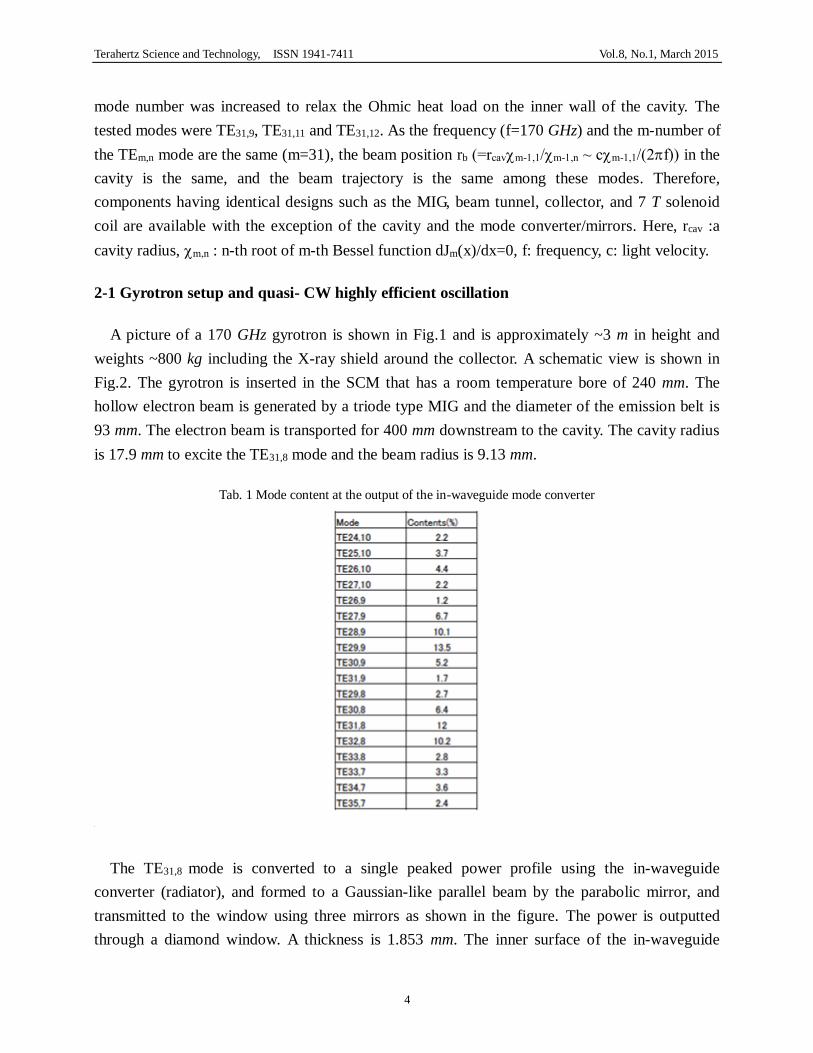
Tab. 1 Mode content at the output of the in-waveguide mode converter
The TE31,8 mode is converted to a single peaked power profile using the in-waveguide
converter (radiator), and formed to a Gaussian-like parallel beam by the parabolic mirror, and
transmitted to the window using three mirrors as shown in the figure. The power is outputted
through a diamond window. A thickness is 1.853 mm. The inner surface of the in-waveguide

Terahertz Science and Technology, ISSN 1941-7411 Vol.8, No.1, March 2015
5
converter has dimple shape (see Fig.2) to convert the original oscillation mode to the many
modes combination to form a single peaked power profile. The mode contents are shown in Table
1. Approximately 18 modes are generated from the single TE31,8 mode, and the final content of
TE31,8 mode is only 12 % at the output. A Si3N4 cylinder is installed as a DC insulator between
the body and the collector to apply the bias voltage for the depressed collector. Here, the collector
is grounded and a high positive voltage 25~30 kV is applied to the body section. The body is
covered with the insulator (blue part of the gyrotron seen in Fig.1).
The triode MIG has an advantage that the beam voltage and the pitch factor of the electron
beam can be controlled independently, therefore, which enables an active control of the beam
parameters during the oscillation to access to the operation point of the maximum efficiency
easily. The output power couples with the 63.5 mm diameter waveguide of via mirrors in the
MOU, where 94.5% of the output power was transmitted to a dummy load. Here a power loss in
the MOU was ~4.5%.
This gyrotron was the first to provide 1 MW quasi-CW operation. High efficiency oscillation
was achieved in the so-called hard excitation region using the active control of the operation
parameters (the resonance frequency at the cavity and the electron beam pitch factor), e.g., 55%
at 1 MW, 57% at 0.8 MW (1 hour operation) and 60% at 0.6 MW. In the quasi-CW operation, the
vacuum pressure in the tube reached to a stable value [11].
Fig. 2 Schematic view of the gyrotron and inner RF components and RF profiles in the cavity (TE31,8 mode) and at
the window

Terahertz Science and Technology, ISSN 1941-7411 Vol.8, No.1, March 2015
6
In actual operation, repetitive operation is unavoidable. The EC system was tested for
reliability by highly repetitive operation of the 170 GHz gyrotron. An 800 kW/ 600 s pulse was
repeated at an interval of 20~30 min at the 52-57% electrical efficiency, which is expected
operation interval of ITER. The beam voltage Vbeam and beam current Ibeam were ~67 kV and ~34
A, respectively, and the depressed collector voltage Vdep was ~24 kV. Seventy-two shots of the 88
trial shots had successful 600 s oscillation without being terminated intermediately. The 16
unsuccessful shots were interrupted for reasons such as a light emission in the tube, an abrupt
beam current increase, or a mode transition to an adjacent mode [13]. To further increase the
system operation ratio, a rapid recovery scenario method should be realized without a sequence
stop. A pitch factor control and/or beam current control using an anode voltage control will be a
powerful tool for this purpose. Developing an operation rapid recovery scenario is a major theme
for a long pulse gyrotron systems.
This gyrotron has been functioning since 2006 and has recorded an output energy of >250 GJ
and its achievements compared too other gyrotrons are summarized in Table 2 with other
gyrotrons.
2-2 Power modulation using anode voltage switching of the triode gun
A 5 kHz full power modulation experiment was performed on a 170 GHz gyrotron. The
gyrotron beam current depends on the voltage between the anode and cathode Vak of the triode
MIG as shown in Fig.3(a), i.e., the beam current Ib shows a nominal value when the switch is
open, and Ib=0 when closed. Using the beam current switching, 5 kHz power modulation was
tried. The configuration of the system is shown in Fig.3(b). This method has following
advantages. As the beam current is zero at no oscillation phase, collector heat load could be
suppressed to half, X-ray decreases, and the total averaged efficiency increases. As the averaged
heat deposition to the cavity is also half, the power can be increased compared to the CW
operation.

Terahertz Science and Technology, ISSN 1941-7411 Vol.8, No.1, March 2015
7
Tab. 2 Status of 170 GHz gyrotron performances in JAEA
Mode
(Power limit) Power Pulse Efficiency
TE31,8
(1.0 MW)
1 MW >800 s 55%
0.8 MW 3600 s 57%
0.6 MW 300 s 60%
TE31,9
(1.2 MW)
1 MW 1 ms 32% w/o CPD
0.6 MW 10 s 51%
TE31,11
(1.6 MW)
1.24 MW 2 s 45%
1 MW 200 s 46%
0.6 MW 1000 s 47%
0.6 MW 2 s 50%
TE31,12
(1.8 MW)
1.56 MW 1 ms 27% w/o CPD
1.03 MW 2 s 40%
0.55 MW 200 s 42%
0.94 MW 50 s - At NFRI [30]
(w/o CPD: operation without depressed collector)
(a) (b)
Fig. 3 (a) Dependence of the beam current on the voltage between the anode and cathode of the triode MIG. (b)
Configuration of the power supply system with the fast switch between anode and cathode
In the experiment, the 5 kHz/60 s operation was demonstrated successfully [16]. The maximum
power achieved was 1.16 MW having an electrical efficiency of 48%.
At the start-up phase of each pulse, if the anode voltage or current ramp-up time is slow, it will
cause a longer duration time of the lower mode (lower frequency). This is not preferable both for

Terahertz Science and Technology, ISSN 1941-7411 Vol.8, No.1, March 2015
8
the application and for the collector heat load since high-power electron beam deposition occurs.
To make the anode voltage rise faster, another fast switch was inserted between the anode voltage
divider and the anode (double anode switch) as shown in Fig.4. This cut the stray capacity of the
anode feeding circuit, and as a result, unwanted charge/discharge was avoided. Fast start-up of
the anode voltage was successful and unwanted mode generation was minimized.
Fig. 4 Configuration of the power supply with dual anode switch for 5 kHz CW power modulation.
3. Multi-frequency gyrotron having triode magnetron gun
3-1 170 GHz TE31,11 mode gyrotron and its multi-frequency operation
A170 GHz TE31,11 mode gyrotron was fabricated for application in ITER. Fig.5 is a picture of
the gyrotron with the SCM and MOU (matching optics unit) and oil tank for high voltage DC
power feeding to the cathode, anode and body terminals.
Many components of the TE31,11 mode gyrotron such as the MIG, beam tunnel, the collector,
the output window (diamond disk), and the insulator for the depressed collector have the same
design as the TE31,8 mode gyrotron. The cavity radius is 20.87 mm. The peak heat load of the
cavity is low compared to the TE31,8 mode, so the 1.6 MW will be possible for the cavity. The
in-waveguide mode converter design is optimized for TE31,11/170 GHz. Since the bounce angle of

Terahertz Science and Technology, ISSN 1941-7411 Vol.8, No.1, March 2015
9
the TE37,13/203 GHz, TE25,9/137 GHz and TE19,7/104 GHz are the same as the TE31,11/170 GHz,
the mode converter acts similarly for these modes. That is to say, the Gaussian-like beam is
formed at the window. These frequencies match the penetration condition of the diamond window
of 1.853 mm (=n*g/2, g : wavelength in the material, n: integer). Furthermore, the electron
beam position and the pitch factor in the cavity can be optimized to excite the target mode by
selecting the optimum parameters of the MIG field BMIG and the anode voltage of the triode MIG,
therefore, the ideal multi-frequency gyrotron will be realized. In Table 3, azimuthal bounce angle
θw, diamond transparent frequency at 1.853 mm in thickness and typical design operation
parameters: beam position rb, cavity field Bc., BMIG, Vak, pitch factor, are summarized for
operation modes and frequencies. On the 170 GHz experiment, 1.24 MW/2 s, 0.6 MW/2 s/50%,
and 0.6 MW/1000 s/47%, etc. were obtained. By optimizing the cavity field Bc, BMIG and the
anode voltage, the 1 MW outputs with Gaussian-like RF beams were obtained both at 137 GHz
and 104 GHz. In addition, recently, the Gaussian output of 203 GHz was also demonstrated at
center of the window as designed.
Fig. 5 Picture of ITER relevant gyrotron, SCM matching optics unit, oil tank.

Terahertz Science and Technology, ISSN 1941-7411 Vol.8, No.1, March 2015
10
3-2 Dual frequency gyrotron for EC H&CD system of JT-60SA
The JT-60SA, an international project between Japan and EU, is currently under construction.
Conceptual picture is shown in Fig.6(a). The toroidal magnetic coils are super conducting
magnets. The major radius of the torus is ~3 m. And the pulse duration is 100 s. The EC H&CD
system is expected to be a local electron cyclotron heating system. Power injection of 7 MW is
expected with nine 1 MW gyrotrons. The frequencies will be determined from the requirements of
the JT-60SA experiment. In Fig.6(b), the cross sectional view of the JT-60SA vacuum vessel and
toroidal plasma is shown along with the position of second harmonic electron cyclotron
resonance frequencies. Here, the toroidal magnetic field at the plasma center is Bt~2.25 T. To
perform both the center and edge heating experiments, a dual-frequency gyrotron operating at
110 GHz/ 138 GHz is expected. The oscillation modes are TE22,8 for 110 GHz, and TE27,10 for
137.5 GHz [31].
Tab. 3 Operation modes for multi-frequency oscillation and these frequencies, azimuthal bounce angle θw, diamond
transparent frequency at 1.853 mm in thickness and typical design operation parameters beam position rb, cavity field
Bc., BMIG, Vak, pitch factor at the beam voltage of 72 kV
Mode:
TE(m,n)
Oscillation
frequency w(deg
)
Transparent
frequency rb(mm) Bc(T) BMIG(T) Vak(kV)
Pitch
factor
(37,13) 203 GHz 65.3665 204 GHz 9.1 7.93 0.31 49 1.35
(31,11) 170 GHz 65.3492 170 GHz 9.13 6.64 0.28 42 1.35
(25,9) 137 GHz 65.3235 136 GHz 9.19 5.35 0.21 36 1.35
(19,7) 104 GHz 65.3003 102 GHz 9.25 4.06 0.172 28 1.32
The cavity radius is 22.8 mm. A thickness of the diamond window is 2.29 mm. The basic
configuration and the outer size are the same as the 170 GHz gyrotrons. Stable 100 s operation
was obtained, which satisfies the final objective of the JT-60SA requirements. Because of the
restrictions of the power supply (minimum voltage of the man power supply is ~62 kV), the total
efficiency is limited below 50%, however, the oscillation efficiencies are 34% and 32% for 110
GHz and 138 GHz, respectively. In Fig.7, there is a conceptual view of the EC system on
JT-60SA.

Terahertz Science and Technology, ISSN 1941-7411 Vol.8, No.1, March 2015
11
(a) (b)
Fig. 6(a) Conceputual picture of JT-SA tokamak. (b) Cross sectional view of the tokamak and the position of the
electron cyclotron resonances for 110 GHz, 130 GHz, and 140 GHz
Fig. 7 Conceptual drawing of the gyrotron array in the Gyrotron hall and the JT-60SA hall.

Terahertz Science and Technology, ISSN 1941-7411 Vol.8, No.1, March 2015
12
(a) (b)
Fig. 8 (a) Picture of Liquid-He free 7 T super conducting magnet (SCM). (b) Cross sectional view of the 7 T SCM.
The sweeping coil is made of Sn3Nb, and others are NbTi.
3-3 Fast step tunable operation with superconducting auxiliary coil
The role of the EC H&CD is the power deposition profile control in the tokamak plasma. For
this purpose, the mirror angle steering is commonly adopted as shown in section.5. Alternative
method is a fast frequency switching of the gyrotron. Fast control of the gyrotron frequency is
firstly demonstrated in KIT by changing the Bc using the inner sweeping solenoid coil [32]. In
JAEA, the SC sweeping coil of SCM is employed [33], therefore, the frequency control system in
CW operation is available. The magnet consists of three sets of coils; NbTi main coil, NbTi gun
coil and Nb3Sn sweeping coil. Fig.8 shows the SCM and its inner coil configuration. The
sweeping speed is 0.2 T/5 sec using a commercial power supply, which corresponds to ~1 GHz/s.
The room temperature bore diameter is 240 mm. First experiment was conducted using the TE31,8
gyrotron. In Fig.9, a time trace of the frequency control experiment is shown. Here, Vb is fixed at
71.0 kV, and Ib=27.4 A. The frequency shifted between 170 GHz and 167 GHz at 3.5 s. The
oscillation modes were TE31,8 and TE30,8, respectively. The power and the efficiency without the
depressed collector are 615 kW (32 %) and 538 kW (27%), respectively. This makes it a prospect
to be used in the power deposition control system that aims for plasma stabilization of
magnetically confined plasma. Because the magnetic filed strength decreases towards the major
radius direction in the case of tokamaks, the power deposition point can be controlled by

Terahertz Science and Technology, ISSN 1941-7411 Vol.8, No.1, March 2015
13
controlling frequencies. Consequently, a very simple power injection system will be available
without a complex rotational mirror in the mm-wave launcher. For reference, the power
deposition point moves roughly ~10 cm by 3 GHz frequency shift in the plasma for the ITER
class tokamak.
Fig. 9 Time traces of beam voltage Vb, beam current Ic, mm-wave signal detected by diode and sweeping coil current
which corresponds to the change of the cavity field. At the bottom of the sweeping current, the TE30,8 mode
(166.8 GHz) was excited. Pulse duration of the pulses is 1 ms as indicated in upper figures.
4. Transmission and launching system
4-1 Transmission experiment [34, 35]
The output power from the gyrotron can be utilized as a high power source for the R&D of the
transmission line and the launcher. Fig.10 shows transmission line composed of the evacuated
waveguide (63.5 mm in diameter) with 6 miter bends and one waveguide switch, polarizer,
directional coupler, evacuation system, in which a simulation of the ITER system is available.
The output power from the gyrotron couples with the waveguide via MOU. As the power profile
of multi-frequency gyrotron is located in the center of the window, good coupling is expected for
multi frequencies. As an example, coupling of the millimeter-wave output of the multi-frequency
gyrotron with the transmission line was tried. Here, the tested frequencies are 170 GHz and 137
GHz. Using two RF beam reflecting mirrors in a matching optics unit (MOU), which are
designed to transform the beam profile of the gyrotron output to the fundamental waveguide
mode (HE11 mode) at 170 GHz, and the high efficiency coupling was demonstrated for two

Terahertz Science and Technology, ISSN 1941-7411 Vol.8, No.1, March 2015
14
frequencies. The measured mode purity of HE11 mode was 96% at 170 GHz and 94% at 137 GHz
operations with the identical mirrors at the fixed mirror position and angle. The results indicate
that the significantly simple dual frequency system can be realized using the gyrotron designed to
output the similar beam profiles at multiple frequency operation.
Fig. 10 Pictures and drawings of the transmission line. The waveguide components with the inner diameter of 63.5 mm
and they are composed of the short and long distance line and they are switched over by an in-line waveguide
switch.
4-2 Launcher development [36]
The mock-up of the equatorial launcher was fabricated according to the current design to study
the mm-wave and mechanical characteristics of the ITER launcher. A cross sectional view of the
mm-wave transmission line in the launcher and a picture of the mock-up are shown in Fig.11 and
Fig.12, respectively. A blanket shield module made of stainless blocks is equipped for neutron
shielding at the top of the launcher. The mm-waves are radiated through the beam duct of the
blanket shield. In the experiment, the power was transmitted to the mock-up launcher through the
40 m evacuated corrugated waveguide. The mm-wave power is radiated from the corrugated
waveguide to the plasma via sequential reflections by fixed mirror and rotational mirror for RF
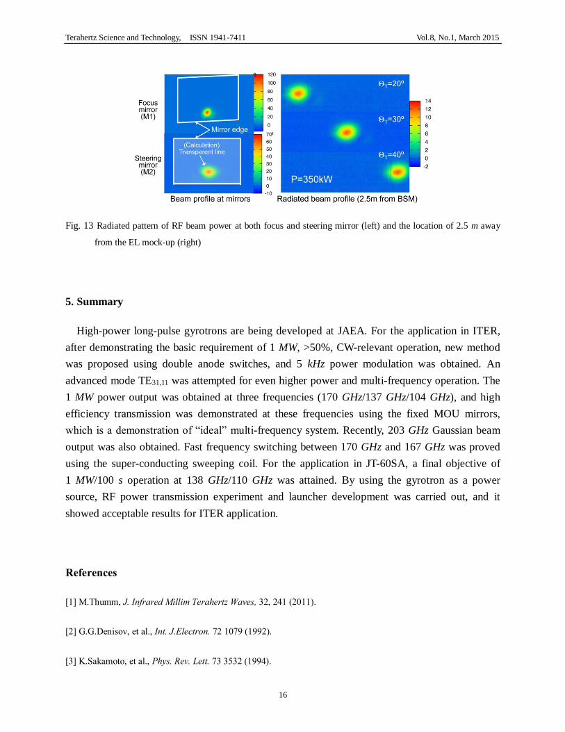
beam steering. The material of the mirrors is Cu. The Gaussian-like beam radiation having a
steering capability of 20 degrees-40 degrees from the EL mock-up was also successfully proved.
The steering speed of the mirror is 3 s for full angle scan. The power was radiated from one of the
8 waveguides. The radiation power profiles measured at the first and steering mirrors and at the
screen placed 2.5 m from top of the launcher as shown in Fig.13. Successful power radiation was
proved. On the other hand, it was found that some of stray RF propagated in the beam duct and
behind the mirrors. It is important to suppress the high order mode in the transmission line to

Terahertz Science and Technology, ISSN 1941-7411 Vol.8, No.1, March 2015
15
mitigate the heat deposition in the launcher. Prototype tests include the fabrication of mock-ups
for the blanket shield modules showed no technological issue on the fabrication and the cooling
functionality.
Fig. 11 Cross sectional view of equatorial port launcher.
Fig.12 Drawing of the launcher mock-up.
Terahertz Science and Technology, ISSN 1941-7411 Vol.8, No.1, March 2015
16
Fig. 13 Radiated pattern of RF beam power at both focus and steering mirror (left) and the location of 2.5 m away
from the EL mock-up (right)
5. Summary
High-power long-pulse gyrotrons are being developed at JAEA. For the application in ITER,
after demonstrating the basic requirement of 1 MW, >50%, CW-relevant operation, new method
was proposed using double anode switches, and 5 kHz power modulation was obtained. An
advanced mode TE31,11 was attempted for even higher power and multi-frequency operation. The
1 MW power output was obtained at three frequencies (170 GHz/137 GHz/104 GHz), and high
efficiency transmission was demonstrated at these frequencies using the fixed MOU mirrors,
which is a demonstration of “ideal” multi-frequency system. Recently, 203 GHz Gaussian beam
output was also obtained. Fast frequency switching between 170 GHz and 167 GHz was proved
using the super-conducting sweeping coil. For the application in JT-60SA, a final objective of
1 MW/100 s operation at 138 GHz/110 GHz was attained. By using the gyrotron as a power
source, RF power transmission experiment and launcher development was carried out, and it
showed acceptable results for ITER application.
References
[1] M.Thumm, J. Infrared Millim Terahertz Waves, 32, 241 (2011).
[2] G.G.Denisov, et al., Int. J.Electron. 72 1079 (1992).
[3] K.Sakamoto, et al., Phys. Rev. Lett. 73 3532 (1994).

Terahertz Science and Technology, ISSN 1941-7411 Vol.8, No.1, March 2015
17
[4] O.Braz, Int. J. Infrared Millim. Waves 18 1495 (1997).
[5] K.Sakamoto, et al., Rev. Sci. Instrum., 70, 1 208 (1999).
[6] K.Felch,, et al., J. Phys.:Conf. Ser. 25 13 (2005).
[7] M.Tumm, et al., IEEE Trans.Electron Devices 52 818 (2005).
[8] A.V.Chirkov, et al., Radiophys. Quantum Electron. 49 344 (2006).
[9] J. Neilson., IEEE Trans. Plasma Sci. 34 635 (2006).
[10] M.Thumm, et al., IEEE Trans. Plasma Sci. 35 1433 (2007).
[11] K.Sakamoto, et al., NAT Phys. 3 411 (2007).
[12] K.Sakamoto, et al., Nucl. Fusion 49 095019 (2009).
[13] K.Kajiwara, et al., Fus. Eng. Des. 86, 955 (2011).
[14] K.Kajiwara, et al., Applied Physics Express, 4 126001 (2011).
[15] A.Litvak, et al., J. Infrared Millim Terahertz Waves, vol. 32, pp. 337-342 (2011).
[16] K.Kajiwara, et al., Nucl. Fusion, 53, 043013 (2013).
[17] H.Zohm, et al., Nucl. Fusion, 53, 073019 (2013).
[18] A.Isayama, et al., Plasma Phys.Control. Fusion, 42 L37 (2000).
[19] R.Prater, Phys. Plasmas 11 2349 (2005).
[20] H.Zohm, Fus. Sci. and Tech., 52, 134 (2007).
[21] V.Erckmann Fus. Eng. Des., 84 131 (2009).
[22] C.Darbos, et al. , Fus. Eng. Des. 84 145 (2009).
[23] T.Omori, et al., Fus. Eng. Des. 86, 951 (2011).

Terahertz Science and Technology, ISSN 1941-7411 Vol.8, No.1, March 2015
18
[24] K.Takahashi, et al., Fus.Sci. and Tech., 52, 231 (2007).
[25] S.Cirant, Fus. Sci. and Tech., 53, 12 (2008).
[26] J.L.Doane, R.A.Olstad, Fus. Sci. and Tech., 53, 39 (2008).
[27] J.Lohr, et al., J. Infrared Millim Terahz Waves 32 253 (2011).
[28] D.Wagner, et al., J. Infrared Millim Terahertz Waves, 32, 274 (2011).
[29] G.G.Denisov, et al., J. Infrared Millim Terahertz Waves, 32, 343 (2011).
[30] YS.Bae, private communication.
[31] T.Kobayashi, et al., to be published in Nuclear Fusion.
[32] K.Koppenburg, et al, IEEE Trans.on Electron Devices, 48,101 (2001).
[33] R.Hirose, et al., IEEE Trans. Appl.Supercond., 18 920 (2008).
[34] K.Takahashi, et al., Rev.Sci.Instr., 82 063506 (2011).
[35] Y.Oda, et al, Rev.Sci.Instr., 84 013501 (2013).
[36] K.Takahashi, et al, to be published in Fusion Sci. Tech., 67 (2015).