Embed Size (px)
Citation preview

This article was downloaded by: [Texas A & M International University]On: 05 October 2014, At: 00:09Publisher: Taylor & FrancisInforma Ltd Registered in England and Wales Registered Number: 1072954 Registered office: MortimerHouse, 37-41 Mortimer Street, London W1T 3JH, UK
Journal of Nuclear Science and TechnologyPublication details, including instructions for authors and subscription information:http://www.tandfonline.com/loi/tnst20
Development of Dust Removal System Using StaticElectricity for Fusion Experimental ReactorsMasanori ONOZUKA a , Yasutoshi UEDA a , Yasushi ODA a , Kenji TAKAHASHI a , YasushiSEKI b , Isao AOKI b , Shuzo UEDA b & Ryoichi KURIHARA ba Mitsubishi Heavy Industries, Ltd. , Minatomirai, Nishi-ku, Yokohama , 220-84b Japan Atomic Energy Research Institute , Naka-machi, Naka-gun, Ibaraki-ken ,319-11Published online: 15 Mar 2012.
To cite this article: Masanori ONOZUKA , Yasutoshi UEDA , Yasushi ODA , Kenji TAKAHASHI , Yasushi SEKI , IsaoAOKI , Shuzo UEDA & Ryoichi KURIHARA (1997) Development of Dust Removal System Using Static Electricityfor Fusion Experimental Reactors, Journal of Nuclear Science and Technology, 34:11, 1031-1038, DOI:10.1080/18811248.1997.9733785
To link to this article: http://dx.doi.org/10.1080/18811248.1997.9733785
PLEASE SCROLL DOWN FOR ARTICLE
Taylor & Francis makes every effort to ensure the accuracy of all the information (the “Content”)contained in the publications on our platform. However, Taylor & Francis, our agents, and our licensorsmake no representations or warranties whatsoever as to the accuracy, completeness, or suitabilityfor any purpose of the Content. Any opinions and views expressed in this publication are the opinionsand views of the authors, and are not the views of or endorsed by Taylor & Francis. The accuracy ofthe Content should not be relied upon and should be independently verified with primary sources ofinformation. Taylor and Francis shall not be liable for any losses, actions, claims, proceedings, demands,costs, expenses, damages, and other liabilities whatsoever or howsoever caused arising directly orindirectly in connection with, in relation to or arising out of the use of the Content.
This article may be used for research, teaching, and private study purposes. Any substantial orsystematic reproduction, redistribution, reselling, loan, sub-licensing, systematic supply, or distribution inany form to anyone is expressly forbidden. Terms & Conditions of access and use can be found at http://www.tandfonline.com/page/terms-and-conditions

Journal of NUCLEAR SCIENCE and TECHNOLOGY, Vol. 34, No. 11, p. 1031-1038 (November 1997)
Development of Dust Removal System Using Static Electricity for Fusion Experimental Reactors
Masanori ONOZUKA'lt , Yasutoshi UEDA*, Yasushi ODA*, Kenji TAKAHASHI*, Yasushi SEKI", Ism AOKI** , Shuzo UEDA** and Ryoichi KURIHARA**
* Mitsubishi Heavy Industries, Ltd. **Japan Atomic Energy Research Institute
(Received October 22, 1996)
Tests to collect and transport metallic and non-metallic dust particles have been conducted using static electricity in a vacuum environment to investigate the applicability of a static electricity dust removal system for fusion experimental reactors. The dust particles are charged by electrostatic induction, floated and collected due to the Coulomb force generated by the AC electric field. They are then transported due to the gradient force induced by the electric curtain of the non-uniform travelling-wave electric field. Using a fully insulated electrode with a single-phase AC voltage up to 15 kV, aluminum and carbon dust were successfully collected. The highest collection rates for the aluminum and carbon dust were around 30 and 2g/min, respectively. The linear-type electrodes, using as high as 22kV of the three-phase AC voltage, transported aluminum dust up to an angle of 60". Applying a guide electrode to the linear-type electrode, the transportation rate was approximately doubled and almost constant at every angle, including a 90" angle. The system transported aluminum dust up to the rate of 13 g/min. The influence of the 0.15T magnetic field on the dust collection and transportation efficiencies was found to be negligible.
KEYWORDS: dust collectors, dusts, deposited material, airborne, sputtering, erosion, dust removal, static electricity, electrostatic force, electric curtain, fusion reactors, thermo- nuclear reactors
I. INTRODUCTION In magnetically confined fusion plasma devices, such
as JET, JT-GOU, TFTR and DIII-D, airborne and de- posited erosion dust has been observed inside the vac- uum vessel after a number of plasma operations(l)-(l0). It is considered that the dust was generated by sputter- ing from the materials facing the plasma and by material erosion due to exposure to high-heat flux during plasma disruptions. In JET, for example, it was found that the main composition of the dust was C and Be from the first walls and Co, Cr, Fe and Ni from the vacuum ves- sel made of inconel The dust ranged in size from a few pm to mm. In addition, various radionuclides ('Be, 51Cr, 56C0, 57C0, 58C0 and 6oCo) and retained tri- tium were found in the dust, revealing that it can be a source of radioactivity and tritium inventory. Dust production strongly depends on the plasma parameters and operational conditions, such as the particle flux on materials, particle energy, energy distribution, plasma duration and plasma disruption number. For example,
* Minatomirai, Nishi-ku, Yokohama 220-84. ** Naka-machi, Naka-gun, Ibamki-ken 319-11.
Corresponding author, Tel. $49-89-3299-4152, Fax. +49-89-3299-4422(G4)/4163(G3), E-mail: [email protected] Present address: Max-Planck-Institut fiir Plasmaphysik, Boltzmannstr. 2, 85748 Garching bei Munchen, GERMANY.
dust production rates in JET and JT-6OU were found to be 96 pg/m2/s for graphite walls and 3.1 pg/m2/s for inconel walls, and 40 pg/m2/s for graphite walls, respec- tively(1) ( 6 ) .
Though it is difficult to extrapolate the amount of dust produced in a vacuum vessel, it is estimated to be 300 kg/yr for fusion experimental reactors wit,h a beryl- lium inner surface of 2,000 rn2(l1). Because such dust be- comes radioactive and accumulates tritium, it must be removed periodically from the vessel, even when strong magnetic fields exist, for safety reasons(5)(7)( 12).
The application of static electricity for a dust removal system has been investigated(ll)( 13) . It is envisioned that the system can collect and transport dust in a vacuum environment. The dust particles are to be charged by electrostatic induction, floated and collected due to an electrostatic attraction (Coulomb) force generated by the electric field. The dust is then transported due to a polarization force (gradient force) induced by the elec- tric curtain of non-uniform travelling-wave electric field. Since the dust removal is carried out using static elec- tricity, which does not require a movable component, the system will be reliable.
Experiments on dust floatation/collection have been previously conducted(13). Applying a DC (direct- current) voltage up to 2.4kV to the circular non- insulated electrode in a vacuum environment, carbon and copper particles with a size of 5-44pm were floated and collected from the bottom of the chamber (ground) to
1031
Dow
nloa
ded
by [
Tex
as A
& M
Int
erna
tiona
l Uni
vers
ity]
at 0
0:09
05
Oct
ober
201
4

M. ONOZUKA et al. 1032
the electrode. Carbon and copper particles were used to simulate non-metallic and metallic dust, respectively. As the electrode and ground were not electrically insu- lated, slight electrical discharge occurred between them (the discharge current was 10 mA). Consequently, the discharged electrons or ions may have neutralized some charged dust particles, thereby lowering the amount of dust collected. Therefore, it was concluded that the elec- trode at, least should be electrically insulated to avoid un- necessary discharge, producing an electric field efficient for dust collection. Current research on dust floatation has focused on improving dust collection efficiency by using an insulated electrode. In addition, dust trans- portation tests have been initiated. The effect of the electric curtain on the dust transportation has been in- vestigated. Furthermore, the influence of the magnetic field on dust collection and transportation efficiencies has been checked to examine the applicability of the static electricity dust removal system for fusion experimental reactors. This report presents recent results.
Chapter I1 de- scribes the concept of the dust removal system. Dust collection and transportation test results are summarized in Chap. 111. The discussion of the experiments is pre- sented in Chap. IV. Conclusions are drawn in Chap. V.
The report is organized as follows.
11. CONCEPT OF DUST REMOVAL SYSTEM A schematic of an example dust removal system is
shown in Fig. 1. The dust on the bottom of the vac- uum vessel is collected on a tray, then transported out of the vacuum vessel. Metallic and non-metallic dust particles are considered. The dust is initially electrically grounded to the floor of the vacuum vessel. When the electric field is applied to the particle by the collection electrode, the particle is inductively charged as shown in Fig. 2(13). Since the particle is grounded to the vessel, the positive charge on the ground is neutralized, so the particle is charged negatively. The negatively charged particle can be then floated by the Coulomb force (qE,), acting against the gravitational force (mg), which is a re- sult of the interaction between the charge and the electric field as shown in Fig. 2. As long as the particle remains charged, the Coulomb force acts on it. Therefore, using the Coulomb force, the dust can be removed from the floor and collected at the required position.
When the electric field is not uniform in space, i.e.,
To Outside
Fig. 1 Example of dust removal system
Electrode +
Electric Field
(a) Induction charging of a particle
+ Electrode
Q Particle
Ground J. mg
////////// (b) Induced Coulomb forces on a floated particle
Fig. 2 Dust floatation concept
the strength of the electric field has a gradient in space, the polarization force (gradient force) acts on the parti- cle due to the interaction between the charged particle and the non-uniform electric field(13)-(15). As a result, the particle moves due to the Coulomb and gradient forces induced by the electric field. When the non-uniform clec- tric field travels, the particle can also travel according to the non-uniform travelling-wave electric field (electric curtain). This phenomenon is employed to transport the collected dust from the tray to the outside of the vacuum vessel.
111. EXPERIMENTS 1. Dust Collection using Static Electricity (1) Dust Collection Test using an Insulated Electrode
To avoid unnecessary discharge between the electrode and the ground and to produce an electric field for ef- ficient dust collection, the dust collection electrode was fully insulated by teflon. Using the insulated electrode, the dust collection test was conducted. While a DC voltage up to 10 kV was successfully applied, which was considerably higher than the 2.4 kV applied for the non- insulated electrode in previous research(13), it was found that dust collection efficiency was not improved. In the case of DC applied voltage to the insulated electrode, al- though the particles are negatively charged and attracted by the electrode, they remain charged and cannot be neu- tralized on the electrode. Therefore, it is considered that the charged particles lower the produced electric field in free space where the dust is placed. Thus, even though a high DC voltage was applied to the electrode, the elec- tric field produced in free space was not high enough to float the particles efficiently.
Instead of a DC voltage, a single-phase AC (alternating-current) voltage can be applied to the in-
JOURNAL OF NUCLEAR SCIENCE AND TECHNOLOGY
Dow
nloa
ded
by [
Tex
as A
& M
Int
erna
tiona
l Uni
vers
ity]
at 0
0:09
05
Oct
ober
201
4

Dust Removal System Using Static Electricity 1033
sulated electrode to improve dust collection efficiency. Using an AC voltage, the polarity of the electrode and t,he electric field strength periodically change. Therefore, the strength and direction of the Coulomb force induced on the particle also changes periodically while the par- ticle travels toward the electrode or toward the ground, ie., it oscillates between the electrode and the ground in the direction of the electric field. Consequently, the dust particles scatter between the electrode and the ground, and can be collected by placing a tray between the elec- trode and the ground as shown in Fig. 1. (2) Dust Collection Test using an AC-driven Electrode
Using the insulated electrode with an AC voltage, dust collection tests have been conducted. A schematic of the device and the main features of the electrode are shown in Fig. 3 and Table 1, respectively. The dust is placed on the bottom of the vacuum chamber, which is electri- cally grounded (grounded electrode). Above the dust, an oval-shaped electrode, made of insulated wire, is po- sitioned. A tray is placed around the electrode to collect the floated particles. Two types of electrodes were tested on carbon and aluminum particles. Type 2 was twice as long (L=30mm) as Type 1 (L=15mm). The tests were carried out in a vacuum environment at a pressure of around 0.01 Pa Torr). The diameters of the parti- cles ranged from 10 to 100 pm. Aluminum particles were used to simulate beryllium dust, because beryllium dust is too toxic to handle in this test facility. Aluminum was chosen because its electrical properties are similar to those of beryllium. Experimental parameters were the applied voltage and the distance between the electrode and the ground.
A voltage of up to 15 kV with a frequency of 60 Hz was applied to the electrodes. Figures 4(a) and (b) present the results, showing the relation of the applied voltage and the dust collection rate for the aluminum dust and carbon dust, respectively. The insulated electrode was initially placed to touch the top of the dust pile on the
AC Power Supply
n
Fig. 3 Experimental apparatus for the dust collection test
Table 1 Main features of dust collection electrodes
Type Insulated electrode Electrode wire diameter 3 mm Conductor Copper, q5 0.8 mm Insulator Teflon Effective length Type 1: 15mm
Type 2: 30mm
ground (electrode distance=O mm). Both metallic and non-metallic dust were floated and collected on the tray in a vacuum environment using both types of AC-driven electrodes. As the applied voltage increases, the dust collection rate increases. The highest collection rates at- tained so far are about 30 and 2 g/min for the aluminum and carbon dust, respectively. The collection rate of the Type 2 electrode with the applied voltage of up to 10 kV is about twice that of the Type 1 due to the length of the electrode. Therefore, the dust collection rate per length is found to be approximately the same for both electrodes. Consequently, the dust collection rate can be controlled by t,he length of the electrode and the applied volt age.
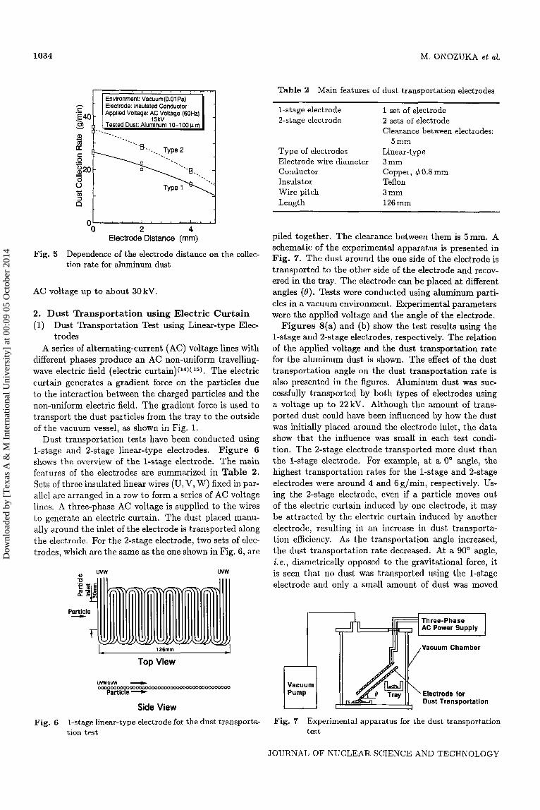
The distance between the electrode and the top of the aluminum dust was varied to examine the effect of the distance on the collection rate. Figure 5 shows the re- sult. It is found that the collection rate decreases al- most linearly with the electrode distance, because the electric field strength decreases as the electrode distance increases. It is anticipated that the dust collection sys- tem for fusion experimental reactors will be required to collect dust within a distance of 10mm from the elec- trode. This can be achieved by increasing the applied
Electrode: Insulated Conductor Applied Voltage: AC Voltage (60Hz) Tested Dust: Aluminum 10-1 00 u m
8*-'. Tvpe 2 ,,I'
I I
01 iv 5 ' 10 15
(a) Aluminum dust Applied Voltage (kV)
, I , ,
Environment: Vacuum(O.01 Pa) Electrode: Insulated Conductor Applied Voltage: AC Voltage (60Hz) Tested Dust: Carbon 10-1 00 1-1 m Electrode Distance: Omm 1' I
Fig. 4
Applied Voltage (kV) (b) Carbon dust
Dependence of the applied voltage on the collection rate for aluminum dust and carbon dust
VOL. 34, NO. 11, NOVEMBER 1997
Dow
nloa
ded
by [
Tex
as A
& M
Int
erna
tiona
l Uni
vers
ity]
at 0
0:09
05
Oct
ober
201
4
1034 M. ONOZUKA et a2.
Environment: Vacuum(O.01 Pa)
.-
dL OO 2 4
Electrode Distance (mm)
Fig. 5 Dependence of the electrode distance on the collec- tion rate for aluminum dust
AC voltage up to about 30kV.
2. Dust Transportation using Electric Curtain (1) Dust Transportation Test using Linear-type Elec-
trodes A series of alternating-current (AC) voltage lines with
different phases produce an AC non-uniform travelling- wave electric field (electric curtain)(14)( 15). The electric curtain generates a gradient force on the particles due to the interaction between the charged particles and the non-uniform electric field. The gradient force is used to transport the dust particles from the tray to the outside of the vacuum vessel, as shown in Fig. 1.
Dust transportation tests have been conducted using 1-stage and 2-stage linear-type electrodes. Figure 6 shows the overview of the 1-stage electrode. The main features of the electrodes are summarized in Table 2. Sets of three insulated linear wires (U, V, W) fixed in par- allel are arranged in a row to form a series of AC voltage lines. A three-phase AC voltage is supplied to the wires to generate an electric curtain. The dust placed manu- ally around the inlet of the electrode is transported along the electrode. For the 2-stage electrode, two sets of elcc- trodes, which are the same as the one shown in Fig. 6, are
uvw ww
L 126mm J Top View
U W U M 4 owoooooooc€Qwoooooooo00000000000M)oooooo
Particle - Side View
Fig. 6 1-stage linear-type electrode for the dust transporta- tion test
Table 2
1-s tage elect rode 2-stage electrode
Main features of dust transportation electrodes
1 set of electrode 2 sets of electrode Clearance between electrodes:
5 mm Type of electrodes Linear-type Electrode wire diameter 3 mm Conductor Copper, 40.8mm Insulator Teflon Wire pitch 3 mm Length 126 mm
piled together. The clearance between them is 5mm. A schematic of the experimental apparatus is presented in Fig. 7. The dust around the one side of the electrode is transported to the other side of the electrode and recov- ered in the tray. The electrode can be placed at different angles ( 6 ) . Tests were conducted using aluminum parti- cles in a vacuum environment. Experimental parameters were the applied voltage and the angle of the electrode.
Figures 8(a) and (b) show the test results using the 1-stage and 2-stage electrodes, respectively. The relation of the applied voltage and the dust transportation rate for the aluminum dust is shown. The effect of the dust transportation angle on the dust transportation rate is also presented in the figures. Aluminum dust was suc- cessfully transported by both types of electrodes using a voltage up to 22kV. Although the amount of trans- ported dust could have been influenced by how the dust was initially placed around the electrode inlet, the data show that the influence was small in each test condi- tion. The 2-stage electrode transported more dust than the l-st,age electrode. For example, at a 0' angle, the highest transportation rates for the 1-stage and 2-stage electrodes were around 4 and 6g/min, respectively. Us- ing the 2-stage electrode, even if a particle moves out of the electric curtain induced by one electrode, it may be attracted by the electric curtain induced by another electrode, resulting in an increase in dust transporta- tion efficiency. As the transportation angle increased, the dust transportation rate decreased. At a 90" angle, ie., diametrically opposed to the gravitational force, it is seen that no dust was transported using the 1-stagc electrode and only a small amount of dust was moved
Vacuum
Vacuum Chamber
Dust Transportation
Fig. 7 Experimental apparatus for the dust transportation test
JOURNAL O F NUCLEAR SCIENCE AND TECHNOLOGY
Dow
nloa
ded
by [
Tex
as A
& M
Int
erna
tiona
l Uni
vers
ity]
at 0
0:09
05
Oct
ober
201
4

Dust Removal System Using Static Electricity 1035
0 10 20 0 10 20 Applied Voltage (kV)
(a) 1-stage linear-type electrode
Environment: Vacuum (0.01 Pa) Electrode: Linear Type (2-Stage)
Applied Voltage (kv) (b) 2-stage linear-type electrode
Fig. 8 Dependence of the applied voltage on the dust trans- portation rate using the 1-stage and the 2-stage linear-type electrodes
using the 2-stage electrode. Before the AC voltage was applied to the electrode, the
dust had to be positioned properly at the electrode in- let. When the dust was placed farther from the electrode inlet, the dust transportation rate was lowered consider- ably. In addition, when the transportation angle was closer to 90' vertical angle, less dust was transported. Since the gradient force induced by the electric curtain is dependent on the distance from the electrode, even at a short distance from the edge (inlet) of the electrode, the induced attraction force on the dust toward the elec- trode is not large enough to overcome gravitational force. Furthermore, especially when the electrode is placed ver- tically, only the electric curtain induced at the edge of the electrode contributes to the removal of dust. The elec- tric curtain along the electrode body barely contributes. Consequently, the electric curtain must be generated in the region where proper gradient force can be applied to the dust for its transportation by the electric curtain. (2) Dust Transportation Test using the Transportation
Electrode with a Guide Electrode To improve dust transportation efficiency, a guide elec-
trode has been added to the trailsportation electrode, as
shown in Fig. 9. A 2-stage linear-type electrode has been employed for the guide electrode and the transporta- tion electrode. Both electrodes are connected to form a smooth electric curtain around them. Table 3 summa- rizes the features of the electrode. The guide electrode is positioned parallel to the dust on the vacuum vessel so that the electric curtain induced by the guide electrode can broadly attract dust particles below the guide elec- trode and move them to the transportation electrode as shown by the arrows in Fig. 9. The particles are then transported by the electric curtain induced by the trans- portation electrode in any direction. The transportation electrode can be set up at different angles (e ) , while the guide electrode stays parallel to the dust. Tests were con- ducted using aluminum particles under an atmospheric environment as well as in a vacuum environment. The experimental parameters were the same as in previous tests.
The test results under vacuum and atmospheric envi- ronments are shown in Figs. lO(a) and (b), respectively. It is found that the transportation rate of the aluminum dust using the linear-type electrode with the guide elec- trode is approximately double that without the guide electrode. The highest transportation rate obtained for aluminum dust was about 13g/min. The dust was suc- cessfully transported at any angle. Under vacuum, the transportation rate was almost constant at every angle. This means that all dust particles that have entered the electric curtain of the guide electrode can be moved in any direction. Accordingly, the gradient force for the aluminum particles of up to 1OOpm in size is greater than the gravitational force. Comparison of Figs. lo(a) and (b) indicates that the dust collection rate under at-
Transportation Electrode (Length: -120mm)
Guide Electrode (Length: -40mm)
\ Particle
@ j O m 0 0 0 0 0 0 0 ooo 0
Vacuum Vessel Dust
Fig. 9 Side view of the 2-stage linear-type electrode wit guide electrode for the dust transportation test
;h a
Table 3 Main features of dust transportation electrode with guide electrode
Type Electrode wire diameter Conductor Insulator Wire pitch Length
Guide electrode Transportation electrode
Clearance between electrodes
2-stage linear-type 3 mm Copper, q5 0.8 mm Teflon 3 mm
-40 mm -120 mm 5 mm
VOL. 34, NO. 11, NOVEMBER 1997
Dow
nloa
ded
by [
Tex
as A
& M
Int
erna
tiona
l Uni
vers
ity]
at 0
0:09
05
Oct
ober
201
4

1036 M. ONOZUKA et al.
Fig. 10
20 h S .- E . v m al m a: C
m a 0 C
c
810 5
E c v)
2 , . , , I , !
10 20 Applied Voltage (kv)
(a) Vacuum environment
. v m a, c m
Environment: Atmosphere (0.1 MPa) Electrode: Linear Type (2-Stage)
Applied Frequency: 60Hz with Guide Electrode 1, Tested Dust: Aluminum 10-100 P m
a c 4
Applied Voltage (kv) (b) Atmospheric environment
Dependence of the applied voltage on the dust transportatioii rate iu vacuum and atmospheric environments using the 2-stage linear-type elec- trode with a guide electrode
mosphere is lower than that under vacuum because of the effects of the viscosity of the air and the higher self- adhesion of the dust due to humidity under atmosphere.
To further improve dust transportation efficiency, op- timal configuration of the electrode should be further investigated.
3. Influence of Magnetic Field on Dust Collection
For the dust removal system to be used in fusion exper- imental reactors, it is likely to be required to operate un- der a strong magnetic field, such as 5T. To confirm the effect of the magnetic field on dust collection and trans- portation efficiencies, a uniform magnetic field of 0.15 T was applied in tests on aluminum dust under an atmos- pheric environment. A schematic of the experimental apparatus of the dust collection is shown in Fig. 11. Two magnet sets consisting of a coil and an iron core are employed to induce a uniform magnetic field of 0.15 T at the center of the magnets. For the dust collection test, the Type 1 electrode was placed parallel to the mag-
and Transportation Efficiencies
Magnet Magnet
Pa
Fig. 11 Experimental apparatus of the dust collection .test under a magnetic field
Environment Atmosphere(O.1 MPa) 5 Electrode: Insulated Conductor
Applied Voltage: AC Voltage (WHz) Applied Magnetic Field: 0.15T Tested Dust: Aluminum 10-1 00 1.1 m Electrode Distance: Omm al
m c a o
+- : without Magnetic Field . -u- : with Magnetic Field c
- :20 - - c v ) -
2
'0 5 10 15 Applied Voltage (kv)
(a) Collection rate
whh Guide Electrode
Applied Magnetic Field: 0.15T Tested Dust: Aluminum 10-100 1.1 m c
a
h Parallel Field
Applied Voltage (kv)
(b) Transportation rate
Fig. 12 Influence of the magnetic field on the collection and the transportation rates for aluminum dust
netic field. For the dust transportation test, the 2-stage lineax-type electrode with the guide electrode was used. The magnetic field was applied parallel and perpendicu- larly to the linear direction of the wires of the guide and transportation electrodes. The transportation angle for the test was set at 90'. The test results of dust collection and transportation are shown in Figs. 12(a) and (b), respectively. Both results show that there is no signs- cant difference between the test with the magnetic field
JOURNAL OF NUCLEAR SCIENCE AND TECHNOLOGY
Dow
nloa
ded
by [
Tex
as A
& M
Int
erna
tiona
l Uni
vers
ity]
at 0
0:09
05
Oct
ober
201
4

Dust Removal System Using Static Electricity 1037
and without it. Even under a vacuum environment, it is expected that the magnetic field will not influence dust removal efficiency.
IV. DISCUSSION Metallic and non-metallic dust particles have been
collected due to the Coulomb force generated by the AC electric field and transported due to the gradient force induced by the electric curtain of the non-uniform travelling-wave electric field in a vacuum environment. It was found that the dust collection rate for carbon dust is less than one-tenth that of aluminum dust. The induced charge q on the particle, due to the electric field between the electrodes, is expressed as fo1lows(l6):
4 = 1.65 X 47T&oR2Eo, (1)
where Eo is the electric field between the electrodes, R the radius of the particle, and EO the permittivity of free space. The Coulomb force on the particle is the product of the charge q and the electric field Eo. For example, under an electric field of 10 kV/cm, it is estimated that the Coulomb force on both the aluminum and carbon particles with a size of 100 pm is of the order of N. The Coulomb force is higher than the gravitational force on both the particles by a factor of 10. Theoretically, the dust collection rate for carbon dust should be similar to that of aluminum dust. One reason for the reduced rate of collection for the carbon dust is considered to be the propensity of carbon dust to have higher self-adhesion than aluminum dust. However, tlie dust generated by sputtering and material erosion in fusion experimental reactors has lower self-adhesion than that in the tests. Furthermore, it is expected that self-adhesion will drop considerably in a vacuum vessel with lower vacuum pres- sure and less moisture. Under such conditions, carbon dust should be more easily removed.
In the dust transportation tests, it was found that the transportation rate peaked at around 13 kV for the 1- stage electrode and around 9kV for the 2-stage elcc- trode with and without the guide electrode. This ten- dency was independent of the transportation anglc. For the travelling-wave type electric curtain, particles move in the direction of the travelling-wave (ie., in the direc- tion parallel to the electrode) accompanied by a couiiter- clockwise rotating motion. Since the induced gradi- ent forces on the particles are in the direction of the travelling-wave (desired direction) and in other direc- tions, it is considered that an electric curtain with a higher voltage scatters some particles beyond where the gradient force can transport them in the desired direc- tion. Consequently, the dust transportation efficiency may be decreased. The transportation speed of the parti- cle in the tests is estimated to be 0.03-0.51 m/s, which is lower than that of tlie travelling-wave (0.54m/s), due to the rotating motion of the particles(17). The transporta- tioii speed of the particle is influenced by the electrode collfiguration (mainly wire pitch), applied AC voltage and its frequency. From the findings, it is concluded that
to improve the dust transportation rate (Z.C., speed) and its efficiency, configuration of the electrode, etc. should be further optimized so that the proper gradient force can be applied to the dust by the electric curtain.
With and without the magnetic field of 0.15 T, the dust collection and transportation efficiency was unchanged. Under a uniform electric field and a magnetic field, the equation of motion for the particle is expressed as(18)(19)
dv dt m- =qEo+qu x B,
where m, v and q are the mass, velocity and charge of the particle, respectively; Eo is the electric field and B the magnetic field. The first term on the right-hand side of the equation is the electrostatic force induced by the electric field, while the second term is the electromag- netic force induced by the magnetic field. In the case when the magnetic field is perpendicular to the electric field and the induced electromagnetic force is comparable t,o the electrostatic force, the trajectory of the particle will be influenced. Consequently, the dust collection and transportation rate will be changed. However, in the ex- periments, the strength of the electric field was about 10 kV/cm, while the magnetic field strength was 0.15 T. In the case of particle velocity of 1 m/s, the electrostatic force is estimated to be much stronger than the electro- magnetic force by a factor of 10'. Therefore, the effect of the magnetic field is negligible as found in the tests. Even for the magnetic field of 5 T in fusion experimental reactors, the influence of the field should be negligible. If the direction of the magnetic field is parallel to that of the electric field, the magnetic field will not influence the particle motion. In addition to the magnetic field, external electric fields, mainly fluctuating fields with a commercial frequency and/or its harmonic frequencies that are produced by the periphcral equipment of the reactor, may exist inside the vacuum vessel during the operation of the dust removal system. However, the ex- ternal fields can be very small compared with that used in the dust removal system. Therefore, there will be no significant influence on dust removal efficiency.
Based on the results of the dust collection tests, effi- cient dust collection can be obtained by optimizing the electrode length, the applied voltage and the distance of the electrode. It is extrapolated that a collection rate of 20g/min for beryllium dust could be achieved in prac- tical operation of fusion experimental reactors. In addi- tion, the dust collection ratc can be improved by lowering the frequency of the applied AC voltage because a lower frequency increases the oscillation amplitude of the dust. For the dust transportation system, the transportation rate must be improved further. In addition to optimizing the electrode configuration, etc. as already mentioned, to increase the transportation rate, multiple stages of the linear-type electrode with a wider inlet can be used. Us- ing more electrodes with a wider particle inlet, a broader electric curtain will be formed to attract more particles, resulting in an increase in the dust transportation rate.
VOL. 34, NO. 11, NOVEMBER 1997
Dow
nloa
ded
by [
Tex
as A
& M
Int
erna
tiona
l Uni
vers
ity]
at 0
0:09
05
Oct
ober
201
4

1038 M. ONOZUKA et ul.
It is therefore expectcd that the deposited dust on the floor of the vacuum vessel will be collected and trans- ported at a rate of 20g/min by the system.
In addition to the removal of the deposited dust, air- borne dust can be removed using static electricity. To collect airborne dust, a number of linear-type transporta- tion electrodes are placed in the vacuum exhaust lines. When fusion plasma is induced in the intermediate mc- uum pressure, the airborne dust will float and travel to- ward the vacuum exhaust lines. Generating the electric curtains along the exhaust lines, the travelling dust par- ticles can be trapped in the electric curtains and trans- ported outside t,he vacuum vessel by the gradient force.
V. CONCLUSIONS The application of static electricity for a dust removal
system has been investigated. It is envisioned that the system can collect and transport dust from fusion exper- imental reactors with a high vacuum environment and a magnetic field. The primary research results are as follows: (1) Using a fully insulated electrode with a single-phase
AC voltage up to 15 kV, aluminum and carbon dust were floated and collected under vacuum.
(2) The highest collection rates attained for the alu- minum and carbon dust were around 30 and 2 g/min, respectively.
(3) The dust collection rate can be controlled by the electrode length, the applied voltage and the dis- tance of the electrode from the dust.
(4) The collection rate for carbon dust is less than one- tenth that of aluminum dust. This is caused mainly by the propensity of carbon dust to have higher self- adhesion than that of aluminum dust.
( 5 ) Using linear-type electrodes with up to 22 kV of the applied voltage, aluminum dust was transported up to an angle of GO” under vacuum.
( G ) Applying a guide electrode to the 2-stage linear-type electrode, the transportatioii rate of aluminum dust was approximately doubled and was almost constant at every angle.
(7) The highest transportation rate for aluminum dust was about 13 g/min.
(8) The magnetic field of 0.15 T did not yield any signif- icant influence on dust collection and transportation efficiencies.
(9) By optimizing the configuration of the electrodes, the applied AC voltage and its frequency, it is ex- pected that a collection and transportation rate of 20g/min can be attained for the beryllium dust in fusion experimental reactors.
Although development is still in progress, research re- sults indicate that the dust removal system using static electricity can collect and transport metallic and non- metallic dust in a vacuum environment with a magnetic field. To test tlie applicability of the system for fusion
experimental reactors, further investigation will be re- quired, including a dust removal test using a conibincd system of dust collection and dust transportation.
ACKNOWLEDGMENT
The authors wish to express their gratitude to Doctors S. J. Piet and L. Topilski of ITER Joint Central Team for their valuable suggestions. This research was conducted as a part of the technology research and development tasks for the engineering design activities of ITER (In- ternational Thermonuclear Experimental Reactor).
-REFERENCES- ( 1 ) Charuau, J., Djerassi, H. : PTOC. 15th Symp. Fusion
Technol., p. 743 (1988). ( 2 ) Roth, J., Ehrenberg, J., Wittmaack, K., Coad, P.,
Roberto, J. B.: J . Nucl. Muter., 145-147, 383 (1987). ( 3 ) Charuau, J., Belot, Y., Cetier, Ph., Drezet, L., Gri-
vaud, L., Peacock, A. T., Wu, C. H.: PTOC. 17th Symp. Fusion Technol., p. 1700 (1992).
(4) Peacock, A. T., Coad, J . P., Dietz, K. J., Knight, A. P.: PTOC. 17th Symp. Fusion Technol., p. 329 (1992).
( 5 ) Miya, N., Nemoto, M., Toyoshima, N.: PTOC. ANS 11th Topical Meeting on the Technol. of Fusion En- ergy, p. 507 (1994).
( 6 ) Masaki, K.: Private Discussion, (1995). ( 7 ) Lyon, R. E., Holland, D. F.: PTOC. 13th Symp. Fusion
Eng., p. 1482 (1989). ( 8 ) Wampler, W. R., Doyle, B. L., Lee, S. R., Pontau,
A. E., Mills, B. E., Causey, R. A., Buchenauer, D., Dylla, H. F., Ulrickson, M. A., LaMarche, P. H.: J. Vac. Sci. Technol., A6[3], 2111 (1988).
( 9 ) LaMarche, P. H., Ladd, P., Umbagh, L., Lewis, M., Cropper, M., Gilbert, J., Collins, J., Winston, J., Crook, D.: PTOC. 17th Symp. Fusion Technol., p. 1172 (1992).
(10) Taylor, P. L., Kellman, A. G., Lee, R. L.: GA-A21329, (1993), in PTOC. IAEA Technical Committee Meeting on Development in Fusion Safety, Toronto, Canada, (1993).
(11) Onozuka, M., Ueda, Y., Takahashi, K., Oda, Y., Seki, Y., Ueda, S., Aoki, I.: PTOC. 16th Symp. Fusion Eng., p. 272 (1995).
(12) Deleanu, L., Djerassi, H., Jones, A. V., ROCCO, P.: PTOC 14th Symp. Fusion Technol., p. 1172 (1986).
(13) Onozuka, M., Ueda, Y., Takahashi, K., Seki, Y., Ueda, S., Aoki, I.: Vacuum, 47, 541 (1996).
(14) Masuda, S.: PTOC. Albany Conf. on Electrostatics, p. 227 (1971).
(15) Masuda, S., Itoh, T., Ando, I., Yamamoto, M., Okamoto, Y.: Record of IEEE/IAS 1977 Annu. Meet- ing , p. 887 (1977).
(16) Cho, A. Y. H.: J. Appl. Phys., 35, 2561 (1964). (17) Masuda, S., Fujibayashi, K., Ishida, K., Inaba, H.:
(18) Jackson, J. D.: lLCla~~ical Electrodynamics”, (2nd
(19) Chen, F. F.: “Plasma Physics and Controlled Fusion”,
Trans. IEEJ, 92-B, 9 (1972), [in Japanese].
ed.), John Wiley & Sons, New York, (1975).
(2nd ed.), Plenum Press, New York, (1984).
JOURNAL OF NUCLEAR SCIENCE AND TECHNOLOGY
Dow
nloa
ded
by [
Tex
as A
& M
Int
erna
tiona
l Uni
vers
ity]
at 0
0:09
05
Oct
ober
201
4