Embed Size (px)
Citation preview

DOEIAU99567-1 (DE97000259)
DEVELOPMENT OF ASPHALTS AND PAVEMENTS USING RECYCLED TIRE RUBBER
Phase I: Technical Feasibility
Technical Progress Report
BY Jerry A. Bullin Rlchard R. Davison charles J. Glover Cindy Estakhrl Raymond W. Flumerfett Travis Bllllter Jay Churn Heamo Koo V h s Sheth Gerald Uphingstone Clint Eckttardt
June 1996
Work Performed Under Contract No. DE-FC04-94AL99567
For US. Department of Energy Office of Industrial Technologies Washington, DC
BY Texas Transportation Institute College Station, Texas


DISCLAlMER
Available to DOE and DOE umlractors from the office of Scientific and Technical Information, P.O. Box 62, ollr Ridge, TN 37831; prices available from (6m6-8401.
Available to the public from the U.S. Dq#lrtmcnt of Commerce, Technology Adrrrrmstra tion, National Technical Information Service, Springfield, VA 22161, (703)487-4650.
. .

I’

DOE/AL/99567--1 (DE97000259)
Dlstributlon Category UC-1414
DEVELOPMENT OF ASPHALTS AND PAVEMENTS USING RECYCLED TIRE RUBBER
Phase I: Technical Feasibility
Technical Progress Report
BY Jerry A. Bullin
Richard R. Davison Charles J. Glover Cindy Estakhri
Raymond W. Flumerfelt Travis Billiter
Jay Chum Heamo Koo Vikas Sheth
Gerald Elphingstone Clint Eckhardt
June 1996
Work Performed Under Contract No. DEFCW94AL99567
Prepared for US. Department of Energy
Office of Industrial Technologies Washington, D.C.
Prepared by Texas Transportation Institute
College Station, Texas


a
DOE/AL/99567- 1
DEVELOPMENT OF ASPHALTS AND PAVEMENTS USING RECYCLED TIRE RUBBER
Phase I: Technical Feasibility
Technical Progress Report
BY Jerry A. Bullin Richard R. Davison Charles J. Glover Cindy Estakhri Raymond W. Flumerfelt Travis Billiter Jay Chum Heamo Koo Vikas Sheth Gerald Elphingstone Clint Eckhardt
June 1996
Work Performed Under Contract No. DE-FC04-94AL99567
' For U.S. Department of Energy Office of Industrial Technologies Washington, D.C.
In Cooperation with Texas A&M University Research Foundation Texas Transportation Institute Department of Chemical Engineering


PREFACE
This report documents the technical progress made on the DOE funded project
"Development of Asphalts and Pavements Using Recycled Tire Rubber" for the time period
covering September 1, 1994 through August 31, 1995. Cost sharing for this study is being
supplied by the Texas Department of Transportation and industry. Bruce Cranford is the Program
Manager for the DOE Office of Industrial Technologies. Ken Lucien is the Project Officer and
M. Laurene Dubuque is the Contracting Officer, both for the DOE Albuquerque Operations
Office. Frank Childs, the Project Technical Monitor, is on the staff of Scientech, Inc., Idaho
Falls, Idaho. Professors Jerry A. Bullin, Charles J. Glover, Richard R. Davison, and Raymond
W. Flumerfelt, together with Cindy K. Estakhri of the Texas Transportation Institute are the Co-
m c i @ Investigators. m e r co-mthors of this report are current PhD candidates Travis Billiter,
Vikas Sheth, and Gerald Elphingstone and masters students Jay Chun and Heamo Kw, and
technician Clint Eckhardt.
Work supported by the U.S. Department of Energy, Assistant Secretary for Energy Efficiency and
Renewable Energy, Office of Industrial Technologies, under DOE Albuquerque Operations Office
Cooperative Agreement DE-FCW-94AL99567.
1

TABLE OF CONTENTS
Page Preface . . . . . . . . . . . . . . . . . . . . . . . . . . . . . . . . . . . . . . . . . . . . . . . . . . . . . . i
Table of Contents 11
List of Figures . . . . . . . . . . . . . . . . . . . . . . . . . . . . . . . . . . . . . . . . . . . . . . . . . . v
List of Tables . . . . . . . . . . . . . . . . . . . . . . . . . . . . . . . . . . . . . . . . . . . . . . . . . ix
Chapter
.. . . . . . . . . . . . . . . . . . . . . . . . . . . . . . . . . . . . . . . . . . . . . . . . .
1 Introduction and Summary . . . . . . . . . . . . . . . . . . . . . . . . . . . . . . . . . . . . . . 1
2 Laboratory Testing and Evaluation ................................. 5
Fractionate Asphalt Material . . . . . . . . . . . . . . . . . . . . . . . . . . . . . . . . . . . 5
Reblend for Aromatic Asphalts . . . . . . . . . . . . . . . . . . . . . . . . . . . . . . . . . 6
Verify Optimal Parameters . . . . . . . . . . . . . . . . . . . . . . . . . . . . . . . . . . . . 7
Curing Temperature as a Variable ............................. 9
Curing Time as a Variable .................................. 9
Rubber Amount as a Variable ............................... 12
Rubber Particle Size as a Variable ............................ 12
Rubber Type as a Variable ................................. 16
Mixing Speed as a Variable ................................ 16
Asphalt Type as Variable .................................. 20
General Conclusions about Curing Asphalt with Rubber . . . . . . . . . . . . . . 20
AgeBlends ............................................. 21 Hardening Susceptibility .................................. 22
Aging Rate ........................................... 27
HardeningRate ........................................ 27 Development of Microductility Test . . . . . . . . . . . . . . . . . . . . . . . . . . . . . 37
Experimental Method (Hveem et al.) . . . . . . . . . . . . . . . . . . . . . . . . . . 38
Modified Experimental Method .............................. 38
Application . . . . . . . . . . . . . . . . . . . . . . . . . . . . . . . . . . . . . . . . . . . 39
for use with Asphalt-Rubber Binders
ii

3 Evaluate Mixture Characteristics . . . . . . . . . . . . . . . . . . . . . . . . . . . . . . . . . 40
Evaluate Compaction Characteristics of Mixtures . . . . . . . . . . . . . . . . . . . . . 40
Evaluate Deformation and Failure of Compacted Mixtures . . . . . . . . . . . . . . . 49
4 Adhesion Test Properties . . . . . . . . . . . . . . . . . . . . . . . . . . . . . . . . . . . . . . 51
Adhesion Tests . . . . . . . . . . . . . . . . . . . . . . . . . . . . . . . . . . . . . . . . . . . 53
Wilhelmy Plate Method . . . . . . . . . . . . . . . . . . . . . . . . . . . . . . . . . . . 53
Gas Adsorption . . . . . . . . . . . . . . . . . . . . . . . . . . . . . . . . . . . . . . . . 56
Adhesion and Cohesion . . . . . . . . . . . . . . . . . . . . . . . . . . . . . . . . . . . 59
Water Susceptibility Tests . . . . . . . . . . . . . . . . . . . . . . . . . . . . . . . . . . . . . 59
Summary of Adhesion Tests . . . . . . . . . . . . . . . . . . . . . . . . . . . . . . . . 59
5 Economic Summary . . . . . . . . . . . . . . . . . . . . . . . . . . . . . . . . . . . . . . . . . 68
. The Rose Refining Process . . . . . . . . . . . . . . . . . . . . . . . . . . . . . . . . . . . 69
Crumb Rubber Modified Asphalt Pavement . . . . . . . . . . . . . . . . . . . . . . . . 70
Capitalcost . . . . . . . . . . . . . . . . . . . . . . . . . . . . . . . . . . . . . . . . . . 70
Maintenance . . . . . . . . . . . . . . . . . . . . . . . . . . . . . . . . . . . . . . . . . . 70
EnergyUse . . . . . . . . . . . . . . . . . . . . . . . . . . . . . . . . . . . . . . . . . . 71
Waste .............................................. 72
References . . . . . . . . . . . . . . . . . . . . . . . . . . . . . . . . . . . . . . . . . . . . . . . . . . . 73
Abbreviations . . . . . . . . . . . . . . . . . . . . . . . . . . . . . . . . . . . . . . . . . . . . . . . . . 77
Notation . . . . . . . . . . . . . . . . . . . . . . . . . . . . . . . . . . . . . . . . . . . . . . . . . . . . . 78
Appendix A: Experimental Methods . . . . . . . . . . . . . . . . . . . . . . . . . . . . . . . . . . 79
Supercritical Fractionation ................................... 79
Pressure Oxygen Vessel (POV) ................................ 82
CorbettAnalysis .......................................... 84
MixingApparatus . . . . . . . . . . . . . . . . . . . . . . . . . . . . . . . . . . . . . . . . . 84
Bending Beam Rheometer . . . . . . . . . . . . . . . . . . . . . . . . . . . . . . . . . . . . 85
Dynamic Shear Rheometer . . . . . . . . . . . . . . . . . . . . . . . . . . . . . . . . . . . 85
Brookfield Rotational Viscometer . . . . . . . . . . . . . . . . . . . . . . . . . . . . . . . 86
... 111

Gel Permeation Chromatography (GPC) . . . . . . . . . . . . . . . . . . . . . . . . . . . 87
Fourier Transform Infrared Spectroscopy (FTIR) . . . . . . . . . . . . . . . . . . . . . 87
Microductility Measurements . . . . . . . . . . . . . . . . . . . . . . . . . . . . . . . . . . 88
Appendix B: OIT Spreadsheets . . . . . . . . . . . . . . . . . . . . . . . . . . . . . . . . . . . . 89
iv

LIST OF FIGURES
Page Figure 2-1. Effect of Curing Temperature on Viscosity @ 60°C . . . . . . . . . . . . . . . 10
10% TG-40 and 90% Fina AC-10
Figure 2-2. Effect of Curing Temperature on Low Temperature Data . . . . . . . . . . . . 10
Figure 2-3. Effect of Curing Temperature on the Solubility of . . . . . . . . . . . . . . . . 11
10% TG-40 and 90% Fina AC-10
Rubber 10% TG-40 and 90% Fina AC-10 I i Figure 2-4. Intermediate and High Temperature Data . . . . . . . . . . . . . . . . . . . . . . 11 !
i 10% TG-10 and 90% Exxon AC-5 1 ; Figure 2-5. Low Temperature Data 10% TG-10 and 90% Exxon AC-5 . . . . . . . . . . . 13
Figure 2-6. Solubility of Rubber in Asphalt 10% TG-10 and 90% Exxon AC-5 . . . . . . 13
Figure 2-7. Effect of Rubber Amount on Temperature Susceptibility . . . . . . . . . . . . 14
Figure 2-8. Low Temperature Data Fina AC-10 and TG Blends . . . . . . . . . . . . . . . 14
Figure 2-9. Effect of Particle S i z e on Temperature Susceptibility . . . . . . . . . . . . . . . 15
Figure 2-10. Low Temperature Data Exxon AC-5 and RS Blends . . . . . . . . . . . . . . . 15
Figure 2-1 1. Effect of Particle S i z e on Solubility of Rubber . . . . . . . . . . . . . . . . . . . 17
Figure 2-12. Effect of Rubber Type on Temperature Susceptibility . . . . . . . . . . . . . . 17
Figure 2-13. Low Temperature Data 90% Fina AC-10 . . . . . . . . . . . . . . . . . . . . . . 18
5 and 10% TG-40 with Fina AC-10
Exxon AC-5 and 10% Rouse Blends
in Asphalt Exxon AC-5 and RS Blends
Fina AC-10 with 10% TG-10 and RS-10
with 10% TG-10 and 10% RS-10
Figure 2-14. Effect of Rubber Type on the Solubility of Rubber . . . . . . . . . . . . . . . . 18 90% Fina AC-10 with 10% TG-10 and 10% RS-10
Figure 2-15. Effect of Mixing Speed on Temperature Susceptibility . . . . . . . . . . . . . . 19 Fina AC-10 with 10% TG-10
Figure 2-16. Effect of Mixing Speed on Low Temperature Data . . . . . . . . . . . . . . . . 19 10% TG-10 and 90% Fina AC-10
Figure 2-17. Effect of Mixing Speed on Solubility of Rubber in . . . . . . . . . . . . . . . . 21 Asphait 10% TG-10 and 90% Fina AC-10

Figure 2- 1 8 . Figure 2.19 . Figure 2.20 . Figure 2-2 1 . Figure 2.22 . Figure 2.23 . FigLre 2.24 .
Figure 2.25 . Figure 2.26 . Figure 2.27 . Figure 2.28 . Figure 2.29 . Figure 2.30 . Figure 2-3 1 . Figure 2.32 . Figure 2.33 . Figure 2.34 . Figure 2.35 . Figure 2.36 . Figure 2.37 . Figure 2.38 . Figure 2.39 . Figure 2-40 . Figure 3.1 .
Figure 3.2 .
Figure 3.3 .
Hardening Susceptibilities of Exxon AC-5 Blends . . . . . . . . . . . . . . . . . 23
Hardening Sc .; .eptibiliti..s of Exxon AC-10 and Blends . . . . . . . . . . . . . 23
Hardening Susceptibilities of Fina AC-10 and Blends . . . . . . . . . . . . . . 24
Hardening Susceptibility of Exxon AC-5 . . . . . . . . . . . . . . . . . . . . . . 25
Hardening Susceptibility of 5/95 Exxon AC-5 and TG -40B . . . . . . . . . . 25
Hardening Susceptibility of 10/90 Exxon AC-10 and TG -40B . . . . . . . . . 26
Comparing the Hardening Susceptibilities . . . . . . . . . . . . . . . . . . . . . . 26 of POV-aging and ENV-aging
Hardening Susceptibilities of Exxon AC-5 and Blends . . . . . . . . . . . . . . 28
Aging Rates of Exxon AC-5 and Blends at 190°F . . . . . . . . . . . . . . . . . 28
Aging Rates of Exxon AC-10 and Blends at 200°F . . . . . . . . . . . . . . . . 29
Aging Rates of Fina AC-10 and Blends at 210°F . . . . . . . . . . . . . . . . . . 29
Aging Rates of Exxon AC-5 and Blends at 140°F . . . . . . . . . . . . . . . . . 30
Aging Rate Kinetics Plot of Exxon AC-5 and Blends . . . . . . . . . . . . . . . 30
Hardening Rates of Fina AC-10 and Blends at 190°F . . . . . . . . . . . . . . . 31
Hardening Rates of W o n AC-5 and Blends at 200°F . . . . . . . . . . . . . . 31
Hardening Rates of Exxon AC-10 and Blends at 210°F . . . . . . . . . . . . . 32
Hardening Rate Kinetics Plot of Exxon AC-5 and Blends . . . . . . . . . . . . 32
Hardening Susceptibilities of Fina AC-10 and Blends at 140°F . . . . . . . . . 34
Hardening Susceptibilities of Exxon AC-5 and Blends at 140°F . . . . . . . . 34 Hardening Susceptibilities of Exxon AC-10 and Blends at 140°F . . . . . . . 35
Change in Delta with Aging for Fina AC-10 and Blends . . . . . . . . . . . . . 35
Change in Delta with Aging for Exxon AC-5 and Blends . . . . . . . . . . . . 36
Change in Delta with Aging for Exxon AC-10 and Blends . . . . . . . . . . . 36
Density Versus GTM Revolution for CRM Asphaltic Mixtures . . . . . . . . 42 prepared with Binders Containing 410 Mesh CRM
Density Versus G V Revolution for CRM Asphaltic Mixtures . . . . . . . . 42 mared with Binders Containing 440 Mesh CRM
Density Versus GTM Revolution for CRM Asphaltic Mixtures . . . . . . . . 43 mared with Binders Containing 480 Mesh CRM
vi

Figure 3.4 .
Figure 3.5 .
Figure 3.6 .
Figure 3.7 . Figure 3.8 . Figure 3.9 .
Figure 3.10 .
Figure 4- 1 . Figure 4.2 . Figure 4.3 . Figure 4-4 . Figure 4.5 . Figure 4.6 . Figure 4.7 . Figure 4.8 . Figure 4.9 . Figure 4.10 .
Figure 4- 1 1 .
Figure 4.12 . Figure 4- 13 . Figure 4- 14 . Figure 4.15 .
Figure 4.16 .
Effect of CRM Particle Size on . . . . . . . . . . . . . . . . . . . . . . . . . . . . 44 Gyratory Compactibility Index (GCI)
Effect of CRM Concentration on . . . . . . . . . . . . . . . . . . . . . . . . . . . 44 Gyratory Compactibility Index (GCI)
Effect of Binder Curing Time on Gyratory . . . . . . . . . . . . . . . . . . . . . 45 Compactibility Index (GCI)
Effect of CRM Particle Size on Gyratory Stability Index (GSI) . . . . . . . . 46
Effect of CRM Concentration on Gyratory Stability Index (GSI) . . . . . . . 46 Effect of Binder Curing Time on . . . . . . . . . . . . . . . . . . . . . . . . . . . 47 Gyratory Stability Index (GSI)
Sample Height Before Extrusion from the . . . . . . . . . . . : . . . . . . . . . . 48 Mold and 24-Hours After Extrusion
Work of Cohesion . . . . . . . . . . . . . . . . . . . . . . . . . . . . . . . . . . . . . 52
Work of Adhesioin .................................... 52
Dynamic Wilhelmy Plate Method Force Balance . . . . . . . . . . . . . . . . . 54
Wilhelmy Plate Apparatus . . . . . . . . . . . . . . . . . . . . . . . . . . . . . . . . 55
Example Experimental Results ............................. 57
Surface Energy of Various Asphalts ......................... 57
Gas Adsorption Experimental Apparatus ....................... 58
Surface Energy of Various Aggregates ........................ 61
Work of Cohesion of Various Asphalts ....................... 61
Work of Adhesion and Cohesion of Various Asphalts . . . . . . . . . . . . . . 62 with Aggregate JGl la in Vacuum
Work of Adhesion and Cohesion of Various Asphalts . . . . . . . . . . . . . . 62 with Aggregate JG21 in Vacuum
Work of Adhesion for Various Asphalts and Aggregates in Vacuum . . . . . 63
Work of Adhesion of Various Asphalts with Aggregate JG1 la . . . . . . . . . 63
Work of Adhesion of Various Asphalts with Aggregate JG21 . . . . . . . . . 64 Work of Adhesion and Cohesion of Various Asphalts . . . . . . . . . . . . . . 64 with Aggregate JG1 la in Water
Work of Adhesion and Cohesion of Various Asphalts . . . . . . . . . . . . . . 65 with Aggregate JG21 in Water
vii

Figure 4.17 . Work of Adhesion for ' xious Asphalts and Aggregates in Water . . . . . . 65
Figure A.1 . Supercritical Unit Process Diagram . . . . . . . . . . . . . . . . . . . . . . . . . . 80
Figure A.2 . Legend for Supercritical Extraction Unit Diagram . . . . . . . . . . . . . . . . 81
Figure A.3 . Pressure Oxygen Vessel Control Panel . . . . . . . . . . . . . . . . . . . . . . . . 83
Figure A.4 . Pressure Oxygen Vessel and Control Panel . . . . . . . . . . . . . . . . . . . . . 83
... Vlll

LIST OF TABLES
Table 1 - 1.
Table 2-1.
Table 4-1.
Table 4-2.
Table 4-3.
Table 5- 1.
Table 5-2.
Page
Proposed Schedule for Completion of Tasks . . . . . . . . . . . . . . . . . , . . . 2
Chemical Composition of Several Asphalts . . . . . . . . . . . . . . . . . , . . . . 6 and Supercritical Fractions
Characterized Asphalts . . . . . . . . . . . . . . . . . . . . . . . . . . . . , . . . . . 60
Characterized Aggregates . . . . . . . . . . . . . . . . . . . . . . . . . . . . . . . . 60 Ranking of Asphalt Aggregate Systems . . . . . . . . . . . . . . . . . . . . . . . 66 Estimated Cost to Produce Aromatic Material . . . . . . . . . . . . . . . . . . . 69 Using a Supercritical Fractionation Unit
CRMA Pavement versus Conventional . . . . . . . . . . . . . . . . . . . . . . . . 72 Asphalt Pavement Comparison


CHAPTER 1
INTRODUCTION A N T smmmy
Approximately 285 million tires are discarded every year. Of these, less than I()() million
are CUrrentiy being recycled. The excess tires not being recycled are placed in landfills and other
waste sites, collecting moisture, breeding insects, and constituting a general nuisance.
A solution to reduce the littering of the environment is to use ground tire rubber in the
~nStnrCtion of the nation's roadways. Currently, about 27 million tons of asphalt =e used each
t0 construct and maintain most of the country's two million miles of roads (Takallou and
Takallou, 1991). If all of the waste tire rubber could be combined with asphalt in road
construction, it would displace less than 6% of the total asphalt used each year, yet could save
abaut 60 trillion BTUs annually. This suggests there is a great opportunity to solve a serious
waste problem, save energy, and improve asphalt roadway life and performance.
The use of tire rubber with various types of asphalt pavements has been demonstrated in
recent years with promising results (Sainton, 1990). Unfortunately, the technology for using
ground tire rubber is relatively undeveloped, and the results of using rubber-asphalt concrete have
been very erratic. The purpose of this project is to provide data needed to optimize the
performance of rubber-asphalt concretes and avoid failures of the past.
The first phase of the overall project is to implement the exploratory development (Phase
I). This was to develop asphalts and recycling agents tailored for compatibility with ground tire
rubber in order to eliminate or reduce compatibility problems to improve compaction properties.
To accomplish this objective, this project has been divided into several tasks. The proposed
schedule for completion of all tasks is given in Table 1-1.
Chapter 2 presents results obtained during the first year of this project on Laboratory
Testing and Evaluation (Task 1). This task was divided into four parts, the first of which was
Fractionate Asphalt Material (Task 1.1). For this portion, various asphalts and Residuum Oil
s v & t i & &tractions (ROSE) fractions were fractionated in a supercritical unit to obtain highly
aromatic material of various viscosities. Shell AC-20 was fractionated to produce a highly-
1

Table 1-1. Proposed Schedule for Completion of Tasks
TASK NAME COMPLETION *
1 Laboratory Testing and Evaluation
1.1 Fractionate Asphalt Material 2/96
1.2 Reblending for Aromatic Asphalts 5/96
1.3 Verifying Optimal Curing Parameters 8/95
1.4 Aged Blends 10196
2 Evaluating Mixture Characteristics
2.1 Developing an Experiment Plan 11/96
2.2 Evaluating Compaction Characteristics of Mixtures 5/96
2.3 Evaluating Deformation and Failure of Compacted Mixtures 8/96
3 Adhesion Test Development
3.1 Adhesion Tests 8/99
3.2 Water Susceptibility 8/99
4 Commercialization Plan 8/99
aromatic, low asphalteme AC-5 asphalt and to also produce various highly-aromatic recycling
agents. Also, various ROSE fractions were obtained from Murphy, Diamond Shamrock, Witco,
and Fina. These were prepared as potmtial asphalts and recycling agents. The second portion of Chapter 2 concerns the Reblending for Aromatic Asphalts (Task
1.2). The supercritical fractions of the Shell AC-20 have been characterized and blended to
produce a large quantity of a highly-aromatic, low-asphaltme AC-5. A Sun 125 recycling agent
was blended with a Murphy resin to produce a highly-aromatic, low-asphaltene AC-5. Also,
Diamond Shamrock and Fina rcsins w e ~ e characterized for possible use as components of highly-
aromatic asphalts.
The next Section involves Verifying Optimal Curing Parameters (Task 1.3). The ultimate
goal of this portion of the research was to determine the optimal curing variables that results in
2

an asphalt-mbber being flexible at low temperatures, resists rutting at road temperatures, and is
compactibi.: at high temperatures. This involves optimizing the following seven variables: asphalt
composition, rubber type, rubber content, rubber particle size, curing temperature, curing time,
and curing shear rate.
The fourth part of Chapter 2 concerns Aged Blends (Task 1.4). The asphalt-rubber blends
prepxed in Task 1.3 were aged in a pressure oxygen vessel (POV) and in a 140°F environmental
(ENV) room to evaluate the aging rates of typical road conditions. The physical properties of be
aged samples were analyzed using a rheometer and Fourier Transform Infrared (FTIR)
Spectrometer. From such data, hardening susceptibilities, aging rates, and hardening rates were
determined for the aged samples.
The final portion of Chapter 2 describes a test that will be used to measure ductilities of
asphalt-rubber binders. The apparatus and procedure used for such experiments was developed
by &lifornia's Division of Highways. Because this method accommodates samples at relatively
low temperatures (35-45"F), it may provide additional support for the low-temperature benefits
of rubber-modified binders.
Chapter 3 focuses on Evaluating Mixture Characteristics (Task 2). The main goal of this
part of the project is to evaluate the modified binders in asphalt concrete mixtures. This chapter
was divided into three subeasks, the first being Developing an Experiment Plan (Task 2.1). This
plan has been developed and implemented within the first year of this study.
The second part of this chapter presents progress made on Evaluating Compaction
Chatacteristics of Mixtures (Task 2.2). The U.S. Army Corps of Engineers gyratory procedure
(ASTM 3387) is being used to evaluate the compaction characteristics of the materials. This is
essentially an instrumented version of the Texas gyratory compactor and can be used to describe
the progression of material changes throughout the compaction process. The procedure is
to address both the compatibility and performance-related issues of mix designs such as
rutting. The next portion of this chapter concerns Evaluating Deformation and Failure of
Compacted Mixtures (Task 2.3). The prepared materials are currently being aged. They are then
to be mpd for deformation and failure using three test methods: (1) "non-destructive" sinusoidal
3

frequency sweeps (fully reversed tension-compression), (2) creep and recovery, and (3) tensile
strength to failure. The mixtures with the optimum combination of resistance to aging and
permanent deformation/craclung will be selected for further study.
Chapter 4 details work accomplished during the first year involving an Adhesion Test
Development (Task 3). The objective of this task is developing methods to measure the adhesive
and cohesive strength of asphalt-rubbedaggregate systems. This chapter is divided into two parts.
The first portion concentrates on describing Adhesion Tests (Task 3.1). The main god of this
portion of the work is to develop improved test procedures to measure aggregate surface energies.
The next section of this chapter concerns Water Susceptibility Tests (Task 3.2). The
objective of this portion of the project is to develop improved tests for water susceptibility.
Although an improved test is currently in the process of development, a theoretical prediction of
water susceptibility is available from surface energy measurements. The aggregates appear &I be
mbre impormt than the asphalts in detamining which mix is water susceptible. This may be due
to the larger acid-base interaction parameter of the aggregates since it is theorized that water
attacks the acid-base portion of the asphalt-aggregate bonds. The mixes that have a large acid-
base interaction parameter are more likely to water strip.
The final chapter focuses on the PerformancelEconomic Update and Commercialization
Plan (Task 4) of this report. First-year work centered on finishing the DOE-OIT Projection
Description which i n d w completing a pcsformanct/economic analysis of the complete system.
-.
4

The overall objective for this portion of the project was to formulate improved asphalts for
use with ground tire rubber as well as improved recycling agents for recycling asphalt rubber (AR)
concretes. In addition, parameters such as rubber type, rubber content, rubber particle size,
mixing temperature, mixing time, and mixing shear rate were studied with these asphalts.
FRACTIONATE ASPHALT MATERIAL
The Supercritical (SC) fractionation apparatus design and operation is described by
Davison et al. (1991, 1992) in detail under TxDOT studies 1155 and 1249. Modifications were
made in the TxDOT Study 1314 (Davison et at., 1994). The unit operates at constant pressure
above the critical pressure of the solvent. It separates heavy petroleum products into a maximum
of four fractions according to solubility in SC solvents. The temperatures of the separators
determine the density of the solvent, therefore, controlling the solvent power in each vessel.
Components of the feed precipitate when no longer soluble in the solvent. The lightest, most-
soluble materials are removed by decompression during solvent recovery.
Numerous runs were made in supercritically fractionating Shell AC-20. Enough Shell AC-
20 was fractionated to produce a highly-aromatic, low-asphaltene AC-5 asphalt and to also
produce various highly-aromatic recycling agents. Furthermore, various ROSE fractions were
obtained from Murphy, Diamond Shamrock, Witco, and Fina. The fractions represent both
potential asphalts and recycling agents. The fractions were evaluated and characterized for use
as supercritical asphalts.
As a means of comparison, Corbett fractions were obtained for various asphalts.
Although, thm fractions were not produced by supercritical methods, the fractions obtained via
Corbett fractionation were used as tools in understanding asphalt chemistry in general. Quantities
of Corbett fractions (saturates, naphthene aromatics, polar aromatics, and asphaltenes) were
5
produced. The composition of 6 asphalts/supercritical fractions are given in Table 2-1. Three
are asphalts- Exxon AC-5, Exxon AC-10, and Fina AC-IO while the other three are supercritical
fractions- Fina Demex Resin, Supercritical Asphalt, and Diamond Shamrock (DS) Resin.
Two of the supercritical fractions had the highest aromatic content: Fina Demex Resin and
Supercritical Asphalt. The remaining supercritical fraction, the DS Demex Resin, has low
asphaltenes but a very high saturate content. The three asphalts all had a lower aromatic content
than the supercritical fractions, with the composition of the three being very similar.
Table 2-1. Chemical Composition of Several Asphalts and Supercritical Fractions
Chemical Composition
ASPHALT 96 Polar 96 Napthene 96 Asphaltenes Aromatics Aromatics 96 Saturates
Exxon AC-5 10.80 31.11 45.52 12.57
Exxon AC-10 12.68 26.60 48.40 12.31
Fina Demex 3.00 38.18 49.65 9.19 Resin
Fina AC-10 14.46 30.12 43.35 12.08
supemitical 2.97 35.74 52.58 8.70 Asphalt
DS Demex 4.13 34.14 46.26 15.47
REBLEND FOR AROMATIC ASPHALTS
Several supercritical fractions produced earlier were used to obtain sufficient quantities
of highly-aromatic low-asphaltene asphalts. The supercritical fractions of the Shell AC-20 have
been characterized and blended to produce a large quantity of a highly-aromatic low-asphaltene
AC-5 supercritical asphalt. Furthermore, a Sun 125 recycling agent and a Murphy resin were
blended to produce a highly-aromatic low-asphaltene AC-5. The supercritical asphalt and the
6

Murphy/Sun asphalt both have an acceptable temperature susceptibility, which is the slope
resulting from a plot of log viscosity (q*) versus l/(Temperature).
Diamond Shamrock and Fina resins were characterized for possible use as components of
highly-aromatic asphalts. The Fina resin has an acceptable temperature susceptibility and its
viscosity of 285 poise at 60°C makes it well suited for use as an asphalt for blending with rubber.
The Diamond Shamrock (DS) resin contained solvent which had to be removed before analysis.
The DS resin, with a viscosity of 626.8 poise at 60°C and an acceptable temperature susceptibility,
can be mixed with rubber to produce an acceptable binder. Chemical analysis for saturate,
aromatic, and asphaltene content utilizing the Corbett column was performed on the Fina and DS
resin with the results listed previously in Table 2-1.
VERIFY OPTIMAL PARAMETER!3
The ultimate goal of the curing study was to determine the optimal curing variables that
allows production of asphalt-rubber that is flexible at low-temperaturey resists rutting at road-
' temperatures, and is compactible at high- temperatures. This task was achieved by investigating
one variable while holding the other variables constant. The verification of the optimal parameters
involved the following seven variables: asphalt composition, rubber type, rubber content, rubber
particle size, curing time, curing temperature, and curing shear rate. Work planned in the first-
year of the project involved using the following materials and conditions:
-Four asphalts: Fina AC-IO, Exxon AC-10, Exxon AC-5, and a Murphy/Sun AC-10.
-Two rubber types: Rouse (RS) and Tire Gator (TG).
-Four rubber contents: 5, 10, 15, and 20%.
-Three rubber mesh sizes: -10, -40, and -80 mesh.
&Variable curing times: Up to 60 hours.
-Three curing temperatures: 350,375, and 400°F.
-Two curing shear rates: 500 and 1550 RPM.
The blending of the various asphalt-rubber binders occurred in the mixing apparatuses
where each binder was contained and heated to the desired temperature within a holding tank and
7

stirred with a mixer blade turned by a 1/16 hp motor. While curing, nitrogen was introduced into
the tank to create an oxygen-free blanket over the binder and thus prevent oxidation.
Furthermore, the effects of the above variables on the binder are being investigated with the
following analytical equipment (see Appendix A for equipment descriptions):
-Bending beam rheometer: Determines low-temperature (5°F) rheological properties.
-Cam-Med rheometer: Determines intermediate-temperature (32 - 194 F) rheological
properties.
-Brookfield rheometer: Determines high-temperature (300400°F) viscosities.
-Fourier transform infrared spectrometer (FTIR): Determines carbonyl areas. -Gel permeation chromatography: Determines molecular-size distributions.
-High pressure liquid chromatography: Determines chemical compositions.
-Rubber recovery: Determines rubber amount in asphalt solution as a result of curing.
A brief summary of the findings a ~ e listed below with detailed discussion of &h variable studied
following.
-Asphalt composition: The compatibility of the asphalt and the rubber is definitely
dependent upon the asphalt composition. Preliminary findings indicate that low-asphaltene
highly-aromatic asphalts are the most compatible. Furthermore, high-asphaltene high-
saturate asphalts are the least compatible
-Rubber type: For Rouse (RS) and Tire Gator (TG) rubber of the same particle size, the
Rouse rubber is better at improving the binder properties than the TG rubber. It
is believed that this can be explained by the fact that for equivalent "labeled" mesh
sizes, i.e. -10, -40, or -80 mesh, the distribution of the Rouse rubber is finer than
the TG rubber.
-Rubber content: Generally, the properties of a binder were found to improve with
increasing rubber content within the range tested, 0 to 20%. The viscosity at
rutring temperatme (140°F). increases, the cnep stiffness at low-temperature (5°F)
decreases, and thekmperature susceptibility d m , improvements in all, with
rubber amtent.' The negative aspect.of increasing rubber content is that the high-
temperature (375°F) viscosity increases with rubber content, leading to pavement
8

compaction problems.
-Rubber particle size: Rubber with smaller particle size allows increased interaction
with the asphalt improving binder properties. It is theorized that this phenomenon
is explained by the smaller rubber particles having more surface area per mass and
volume than the larger rubber particles.
-Curing time: The binder properties improve with curing time within the range tested,
0-60 hours.
-Curing Temperature: The rate of asphalt-rubber interaction, and thus the rate of
improvement in binder propert~es, increases with higher curing temperatures within
the range studied, 350400°F. -Curing shear rate: A higher shear rate increases the rate of asphalt-rubber interaction
improving binder properties at a faster rate. The curing process is apparently mass-
* transfer limited since a higher shear rate allows greater dispersion, and thus better
interaction, of the mixture.
Curing Temperature as a Variable
It was suspected that a higher curing temperature would allow a faster reaction rate
between the asphalt and rubber when being cured. Figure 2-1 shows that a higher curing
temperature produces a binder with a higher viscosity at 60°C. Also, the binder cured at the
higher temperature appeared to have a lower creep stiffness at -15°C as evidenced in Figure 2-2.
The improvement in the binder's physical properties can be attributed to the additional
amount of rubber going into the asphalt solution as a result of the higher curing temperature.
According to Figure 2-3, more rubber dissolves in the asphalt when cured at a higher temperature.
Curing Time as a Variable
By extending the amount of time a binder is cured, more rubber should go into solution
with the asphalt. This was expected to improve intermediate- and low-temperature properties and
reduce the high-temperature viscosity, all relative to the less-dissolved state. Figure 2-4 shows a binder's temperature susceptibility, the slope of a In q* vs.
9

0) r 0 P - - t
6000 o cured e 4 0 0 0 ~ Fina A'C-10 with 10% TG-40 mesh rubber 4
cured Q 375OF Cured at 3 different temperatures Q 500 RPy
5000 ~ cured B 35OoF
4000 1 F
3000 1 * 8
2000
looo 1 8
c
o ~ " " ~ " i ' " " ' " " ' ~ " ' . i 0 10 20 30 40 50
Curing Time (hn)
Figure 2-1. Effect of Curing Temperature on Viscosity 10% TG-40 and 90% Fina AC-10
200
2so i so - -
0 I I I 1
0 10 20 90 40 50 I
i Curing Ti- (hn)
Figure 2-2. Effect of Curing Temperature on Low Temperature Data 10% TG-40 and 90% Fina AC-10
10

P P k 2
t i
"
- 1 0 10 20 30 40 LO
Curing Time (hrs)
Figure 2-3. Effect of Curing Temperature on the Solubility of Rubber 10% TG-40 and 90% Fina AC-10
10'
8
2 9
0
m
n
10'
P
3 l o a - 0 c.
F 10'
10' o.a
....... _ _ A A
A A A -.... I , , . , I , , , ,
20 0.0025 0.0030 0.0035 0.0040 1K (IC')
Figure 2-4. Intermediate and High Temperature Data 10% TG-10 and 90% Exxon AC-5
11

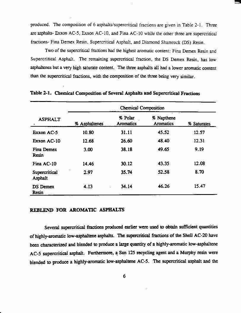
l/(Temperature) correlation, decreases with an increase in curing time. In addition, the viscosity
of the binder decreases as curing time increases at high temperatures. According to Figure 2-5,
extended curing lowers the creep stiffness of the binder. Again, these improvements in the
binder's physical properties can be attributed to the additional amount of rubber that dissolves into
the asphalt as a result of the extended curing time (see Figure 2-6).
Rubber Amount as a Variable
To study the effects of the amount of rubber in a given binder, various samples were
prepared using two different concentrations of rubber, 5 and 10%. All other curing parameters
were held constant except for the amount of rubber in the binders.
Increasing the amount of rubber in a binder was expected to benefit some physical
properties but hinder other properties. The low and intermediate temperature properties benefit
4th the additional amount of rubber. Figure 2-7 shows that the binder cured with 10% rubber
has a lower temperature susceptibility than the binder cured with less rubber. However, at high
temperatures, the binder with 10% rubber has a higher viscosity. Figure 2-8 reveals that the creep
stiffness is lower for the binder containing the larger amount of rubber.
Rubber Particle Size as a Variable
The effect of mesh size on the curing p~ocess was evaluated by preparing binders using the
various available mesh sizes. Theoretically, smaller rubber particles are much more easily
dissolved in asphalt than larger rubber particles. The smaller graded rubber reacts faster when
cured with asphalt because of the increased surface am. Therefore, if better dissolution improves
asphalt-rubber properties, then using smaller rubber particles benefits all physical properties of
a binder: a lower creep stiffness at low temperatures, a lower temperature susceptibility in the
intermediate temperature region, reduced viscosities at high temperatures (compared to the less-
cured state) and reduced curing time.
Figure 2-9 shows that .the kmpemtm susceptibility is lower for the binder cured with the
smaller @e!d rubber (-80 mesh rubber). This figure also reveals that the binder containing the
-80 mesh mbber has lower viscosities at the higher temperatures. From Figure 2-10, it is evident
12
' - 10%TG-lO Exxon 'Ad-5'with ' l O k td-10 Aesh rubber ' ' TANK ' Cured at 375 F and 500 RPM
,OF 1 1
0 0,
0 v)
(0
100
t c
1 /Tank I @ t
0 0 0 0
0 ~ " " " " " . " ' " " " " " 1 0 10 20 30 40 so
Curlng Tlmo (hn)
Figure 2-5. Low Temperature Data 10% TG-10 and 90% Exxon AC-5
10 -lonTG1O/ Eaton k - 6 wtth ld TG-10 m& rubber
C u r d at 375 F and 500 RPM
4 .i 0 1 . . , . 1 . . . . 1 , . . , 1 . . , ,
10 20 30 40 50 Curing T i m (hm)
Figure 2-6. Solubility of Rubber 10% TG-10 and 90% Exxon
in Asphalt AC-5
13

I ~-
1 o9
10'
CI
3 B lo3 n - E
10'
t
i O FINA AC-10 TANK, HT
Fina AC-10 with 5 and 10°/~ TG-40 mesh rubber Cured for 24 hours @ 375 F and 500 RPM
Figure 2-7. Effect of Rubber Amount on Temperature Susceptibility 5 and 10% TG-40 with Fina AC-10
w
g 200 " " P T M k
5
6 "E5 O O 10 20 30 40
so Curing Tim (hn)
Figure 2-8. Low Temperature Data Fina AC-10 and TG Blends
14

a
' "8- RS-80. IT . - * - - - RS-40. IT
10' "-8 -RS-10. IT
IExxon AC-5 and Rouse Blends ICured for 24 hours at 375 F and 500 R
"1- . EXXON AC-5 TANK. IT o RS-80. HT
AS-40. HT i 0 0) v EXXON AC-5 TANK, HT
o RS-10, HT v) 1 9 ///.
_. I
J
0 0 ; m 0 0 ......... 1 m 8 g'' T '
lBIob2o I I I 1
0.0025 0.0030 0.0035 0.0040 1K (K')
Figure 2-9. Effect of Particle Size on Temperature Susceptibility Exxon AC-5 and 10% Rouse Blends
1 so
100
50
r
I b
0 - 0
- ."Q--.S% Rs"o RS40 C u r d at 375 F and 500 RPM - .s% RSdO
Exxon AC6 and R o ~ k rubber b&n&
-c. 10% RS10 I 1
0 0.". ................................... ...................................................... L"" b-""
- 4 4 &e." ......................... .................. - - - -- ...........................
" 0 '1 10 20 3 0
Curlng lime (hn) 40 50
Figure 2-10. Low Temperature Data Exxon- AC-5 and RS Blends
15

that the binder cured with the smaller graded rubber has the lower creep stiffness. Again, these
improved physical properties can be explained by the fact that the smaller graded rubber goes into
the asphalt solution at a faster rate (see Figure 2-1 1).
Rubber Type as a Variable
Rubber used during experimentation was obtained from two sources. Tire Gator rubber
with mesh sizes of -10 and -40 was received from Granular Products located in Mexia, Texas.
A second supply with mesh sizes of -10, -40, and -80 was obtained from Rouse rubber located in
Vicksburg, Mississippi. Binders were cured to study the differences of these two rubber sources.
According to Figure 2-12, the binders cured with the Rouse rubber produced a lower
temperature susceptibility. Also, the binders ivith the Rouse rubber had lower viscosities than the
Tire Gator rubber at high temperatum. Figure 2-13 shows that the creep stiffness for the binders
&red with the Rouse rubber are lower than the ones prepared using the Tire Gator rubber. These
differences in the binders' physical properties are attributed to the amount of rubber going into
solution after curing. Figure 2-14 reveals that more rubber is dissolved in the asphalt for the
binder cured with the Rouse rubber. Such results suggest that the Rouse rubber reacts better with
asphalt than the Tire Gator rubber. For a given mesh size, the Rouse rubber has a finer gradation
than the Tire Gator rubber. This finer gradation of the Rouse rubber is thought to explain its
increased reactivity.
Mixing Speed as a Variable
TWO blending speeds were used to am the asphalt and rubber to see if an increased mixing
speed attained improved binder physical properties at a faster rate. Binders were cured using
mixing speeds of 500 or 1550 RPM.
Figure 2-15 shows that the temperature susceptibility for the binder cured for 2 hours at
1550 RPM is comparable to that of the binder cured for 24 hours at 500 RPM. The viscosities
at high temperatures show a similar cornlation. From Figure 2-16, it is evident that the creep
stiffness for the binder cured for a short time at 1550 RPM is similar to that of the binder cured
for a much longer time at 500 RPM. The solubility experiment suggests that the rubber in the
16

10 - 10% RS-80 1 " " I " " l " "
.+,... ~ ~ - 4 0 E u o n AC-5 and Rouse rubber blends - 1 . i o % Rs- io Cured at 375 F and 500 RPM
4 t t c
Figure 2-11. Effect of Particle Size on in Asphalt Exxon AC-5 and
Solubility of Rubber RS Blends
1 07 - 10% R S l O ...*". 10% 10-10 4 - R N A AGlO TANK
I ' " I " ' I " '
10' ;Fim AG10 wlth 10% TG-10 and RS-10 - m h rubber 8 :Curd tor 24 hour8 at 375 F and 500 RPM s
2 10' r
1 0 4
s 0
- F
0 .)
0 P
2 - CI . 10' F
=' / = 2 1 146-1 3 dy12521 X) R= 0.99999 --/= 7.bO146-15: qlM87x) R= 0.99991 - - y * 1.9628-17 dy 5057X) R= 0.99997
0.0026 0.0028 0.0030 0.0032 0.0034 0.0036 lrr (K')
Figure 2-12. Effect of Rubber Type on Temperature Susceptibility Fina AC-10 with 10% TG-10 and RS-10
17

350 - 1050 TG-10 1 1 ' ' ' I ' ~ ' ~ , ~ ~ , :
Cured at 375 F and 500 RPM 10% RS-10 mesh rubber
-.Q... 10% RS-10 Fina AC-10 with 10% TG-10 and A TANK !
0 0, v) g 200 F @ F
o ~ ~ ' ' ' ' ' ' ' ' ' ' " ' ' ' ' ' ' ~ ' ' ' ~ i 10 20 30 40 so Curing Time (hn)
Figure 2-13. Low Temperature Data 90% Fina AC-10 with 10% TG-10 and 10% RS-10
10 - 10% RS-10 I " " I " " I " "
-*-- 10% TGlO FiM AG10 with 10% TG-10 and 10% RS-10 mash r u b k r
C u r d at 375 F and 500 RPM 8 - -
6 - -
4 -
- .... __.. .......... ......... /.. 0 - ......... 0.. ......... ..........
-3
0 10 20 30 40 . 50 Curing T i m (hn)
- . Figure 2-14. Effect of Rubber Type on the Solubility of Rubber 90% Fina AC-10 with 10% TG -10 and 10% RS -10
18

.- 1 4- cured at 1550 RPM lor 2 hrs , -..e-.. cured at 500 RPM lor 24 hrs
I , , I " '
4 - FlNA AC-10 TANK
lo' [Fina AC-10 with 10% TG-10 mesh rubber Cured at 1550 RPM for 2hr and
@ lo5 i 500 RPM for 24 hrs
// , .g /
i
. . . . . . . . . 5!/
0.0026 0.0028 0.0030 0.0032 0.0034 0.0036 1fr (K')
Figure 2-15. Effect of Mixing Speed on Temperature Susceptibility Fina AC-10 with 10% TG-10
350 "t&OMK)RPM ' " " ' " " ' 1 " " -
o cumdO1550RPM A TANK
2 300
.;
L - Y) FIM AGlO wlth 10% TO-10 mesh rubber
C u d at 375 F and at 2 dlffomnt rh.rr ratma p 250 1 6 0 0
-
Q 200 t- lank - 0 t
' 0 O t " " 1 " " " " ' 1 " " " " ' ~ 10 20 30 40 so
Curing Time (hn) i '
Figure 2-16. Effect of Mixing Speed on Low Temperature Data 10% TG-10 and 90% Fina AC-10
19

binder cured at a high mixing speed goes into the asphalt solution at a faster rate than the binder
cured at a much slower mixing speed (see Figure 2-1 7). From this it would appear that the curing
time could be reduced by using higher mixing speeds.
Asphalt Type as Variable
Numerous binders were prepared using three base asphalts: a Fina AC-10, an Exxon AC-
5 , and a Murphy/Sun AC-10. According to literature, a softer asphalt reacts with rubber at a
faster rate. This was clearly evident during experimentation. The binders prepared using the
Exxon AC-5, which is softest base asphalt, yielded superior physical properties when compared
with the other two asphalts.
General Conclusions about Curing Asphalt with Rubber
The extent to which the rubber dissolves into the asphalt is very dependent upon the curing
environment. Under the curing conditions studied, dissolving the rubber was found to improve
the properties of a binder. However, future work should be done to verify this conclusion, since
it is doubtful that complete destruction of the rub& molecule, and thus its elasticity, is desirable.
That is, the optimization of binder properties is very dependent on. the extent to which the rubber
particle is devulcanized and/or depolymerized.
In this study, the rubber dissolved faster with a higher curing temperature, a longer curing
time, and a faster mixing speed. If dissolving rubber is -le, the standard curing temperature
of 350°F and curing time of 1 hour (Takallou and Takallou, 1991) may not be optimal, since
increasing temperature and curing time greatly increases the rate of rubber degradation.
Furrhermm, the shear rate of mixing is a very important variable which should be studied in the
future. -
The chemical composition of the asphalt, the rubber mesh size, and the rubber content
were all detelmined to be important variables. Apparently, increasing the aromatic content of an
asphalt increases the rubber and-asphalt reaction, Faster reaction rates can also be obtained by
using finer rubber gradation, with increased surface area per mass of the smaller particles allowing
for faster reaction ram. Finally, the benefits of adding rubber were directly related to the rubber
20

L Fina AC-10 with 10% TG-10 mesh rubber Cured at 375 F and at 2 different shear rates
0 10 20 30 40 so Curing lime (hrr)
Figure 2-17. Effect of Mixing Speed on Solubility of Rubber in Asphalt 10% TG-10 and 90% Fina AC-10
content, over the range of content studied.
AGE BLENDS
Asphalt and rubber blends were prepared under various curing conditions and were aged
in ' the pressure oxygen vessel (POV, see Appendix A for description of POV apparatus), or
equivalent device, adequate to evaluate aging rates of typical road conditions. Three asphalts-
Exxon AC-5, Exxon AC-10, and Fina AC-10, and twelve asphalt-rubber blends cured at 375°F
for 12 hours and 500 RPM were aged in several POVs and the ENV mom. These samples are
listed below:
(Total of 3)
Fina AC-10
Exxon AC-5
21

Exxon AC- 10
ber Blends: (Total of 12, 3 asphalts x 4 blends)
4 blends of each asphalt:
2 blends: 5 % and 10% TG-40 B, where'B stands for retreading shop buffings,
which were used in the feedstock to produce this rubber
2 blends: 5 % and 10% RS-40
The POVs were utilized at three temperatures- 190, 200, and 21o"F, under atmospheric
air for up to 2 months, to obtain kinetic data on each of the binders which will subsequently be
verified with 140°F data. The ENV room was maintained at 140°F with air at atmospheric
pressure. The ENV room samples were aged up to 7 months.
The POV and the ENV mom samples have been analyzed using FI'IR and the Carri-Med
rhkmeter. Furthermore, bending beam analysis was performed on 15 tank (TK) (unaged) blends
and the corresponding 15 blends that have been aged approximately 2 months at 140°F in the ENV
room.
Generally, initial results show that rubber is beneficial to a binder's oxidative aging
characteristics, with the hardening susceptibility of an asphalt-rubber binder being less than the
base asphalt of that binder. Additionally, the hardening rate of an asphalt-rubber binder is less
than the base asphalt of that binder. Preliminary bending beam results show that the creep
stiffness increases with aging time. Pertinent results from the aging tests are given below.
Hardening Susceptibility
Figures 2-18,2-19, and 2-20, reprtsenting Exxon AC-5, Exxon AC-IO, and Fina AC-10
asphalt-rubber blends that were POV-aged at temperatures of 190, 200, and 210°F under
atmospheric air, show that the hardening susceptibility, the slope of a log viscosity (q*) versus
carbonyl area plot, decreases and thus improves, with increasing rubber content. Figures 2-18,
2-19, and 2-20 also show that the amount of improvement in the hardening susceptibility is asphalt
dependent.
The hardening susceptibility was also determined to be independent of POV-temperature
22

EXXON AC-5 AND BLENDS POV-AGED DATA "E- EXX A C 5 I
1 O5 -E .5/95. EXX AC-5, TG 4 0 8 , , , , , , I " ' J
i - - 10/90. EXX AC-5. TG -408 Blends cured at 375 OF and 500 rpm 1 A .5/95. EXX AC-5. RS -40 for 12 hours under N2
CI m i - - VI 0
- ....P . . 10/90. EXX AC-5. RS -40 - n 0
- (D 10'
r/ 0
POV-Aged at 190,200, and 21 0 OF /-
Y - o with Atrnospherlc Air ,
I
to 0
.d 0
0
C -
c 9
- Y = 225.1 . W2.85~) Rm0.9706
r )r
- . Y = 514.2 q 2 . 5 5 2 ~ ) Ra 0.9746
a F
- - . Y = 963.2 * q 1 .Wx)
0.9767 y 1055 * w l . 7 1 1 ~ ) R=
0.948 . Y 432.9 w2.189~) Fhc
RS0.9738
. . . .
. . . . . . . . .
l o ~ . ~ " ' l " ' ~ " " " ' l " " " ' 0.8 1 1.2 1.4 1.6 1.8 CARBONYL AREA
Figure 2-18. Hardening Susceptibilities of Exxon AC-5 and Blends - uo( AGIO EXXON AC-10 AND BLENDS
POV-AGED DATA 4 - 6/95. w( AG10. TO 40
- + .10100, w( AC-10. TO -408
- -Y=1062*eA(2.827x)R=O.W82 - - - - y 943.4 ~'f2.674~) R= 0.9764
y = 1051 ~''(2.155~) R= 0.98W
y = 1446 e 2 . 2 8 7 ~ ) R= 0.9761 I , o , l n I , I I , , I , , ,
. . . . . . . . .
1 1.2 1.4 1.6 1.8 CARBONYL AREA
Figure 2-19. Hardening- Susceptibilities of Exxon AC-10 and Blends
23

- FlNA AC-10 , FlNA AC-10 AND BLENDS POV-AGED DATA
,o l o 5 0
U tD
E 0
H 0
104 9 i a LI
- I - * . 10/90, FlNA AC-10, TG -408
A . - 5/95. FlNA AC-IO, RS -40
...P-.- 10/90. FlNA AC-10 RS -40
POV-Aged at 190,200. and 210 O F I with Atmospherlc Alr - - I
- "
. . . .
b E
. . . . . . . . . Y = 1267 t~(2254~) R; 0953
Blends cured at 375 OF and 500 rpm . for 12 hours under N,
10' " " " ' ~ " ' ~ " ' ~ " ' ~ " ' ~ ~ ~ I
0.8 1 1.2 1.4 1.6 1.8 2 2.2 CARBONYL AREA
Figure 2-20. Hardening Susceptibilities of Fina AC-10 and Blends
within the range studied, 19@210"F. This is shown by Figures 2-21, 2-22, and 2-23, representing
ban AC-5, (5195, TG -40, Ehon AC-3, and (10/90, TG 40, Exxon AC-5) aged at the above-
mentioned POV conditions, with the scatter of the data points around the straight line are no worse
for the asphalt-rubber blends than the asphalt. This conclusion agrees with previous work by our
research group that showed that the hardening susceptibility of an asphalt was independent of
POV-aging temperatwe (Lau e€ al., 1992). However, this conclusion contradicts earlier asphalt-
rubber high-pressure aging results, obtained using high-pressure (300 psia) oxygen, that showed
the hardening susceptibility was dependent upon the POV-aging temperature (Bullin et al., 1994).
Further analysis yielded that the hardening susceptibility of an asphalt-rubber is however
not independent of temperature over the tem-re range studied, 140-21o"F, with the 140°F-
aged data and hardening susceptibility line lying distinctly above and away from the POV-aged
data and hardening susceptibility. This is shown in Figure 2-24 for an Exxon AC-5 asphalt-rubber
blend. This phenomenon complicates the mathematical analysis required to investigate the kinetics
of Whdt-rubber oxidation: The differen-ce in the, activation energies of the two distinct
24

POV-AGED DATA EXXON AC-5
1 o s C , , , , , , , , , , , , , , , , , . , , , , , , . , , , , I
+ EXX AC-5 - y = 225.1 * e"(2.85~) R= 0.97oij
i 0) v)
P
1
I - 0 POV-Aged at 190.200. and 21 0 'F 1 - with Atmospheric Alr 1
i
0 0
D E m
(c1 t
10b.7 J 0.8 0.9 1 1.1 1.2 1.3 CARBONYL AREA
1
Figure 2-21. Hardening Susceptibility of Exxon AC-5
EXXON AC-5 WITH 5% T W O B POV-ACIED DATA
105 , , , , 1 , , , , 1 , , , , 1 , , , , 1 , , , , 1 , , , , 1 , , , , 1 , , , ,
- *!VOS.EXXACS,TG-408 - y = 5142 8 (̂2552~) R= 0.9746 :
2 c. . POV-Aged at 190,200, and 2109
8
.)
0 wlth Atmospheric Air
Blends cured at 375 OF and 500 rpm for 12 hours under N,
I. Figure 2-22. Hardening Susceptibility of 5/95 Exxon AC-5 and TG -40B
25

a
EXXON AC-5 WITH 10% TG -408 POV-AGED DATA
1 os " " " " l " ' i " ' J
i Blends cured at 375 OF and 500 rpm
for 12 hours under N,
1 ~ ~ ~ " ~ " " " " " ' ~ ~ ~ ' 1 0.8 1 1.2 1.4 1.6 1.8
CARBOWL AREA
Figure 2-23. Hardening Susceptibility of 10/90 Emon AC-10 and TG -40B
Blends cured at 375 OF and 500 rpm for 12 hours under N,
l ~ o a l ' " " ' " " ' ' ' ~ ' ' ' ' ' " I 0.6 - 0.8 1 1.2 1.4 1.6 1.8
CARBONYL AREA
Figure 2-24. Comparing the Hardening S,usceptibilities of POV-aging and ENV-aging
26

components of the asphalt-rubber blend may explain this phenomenon. Furthermore, the
hardening susceptibility is improved by the addition of rubber at 140°F. This is shown in Figure
2-25 for Exxon AC-5 and Exxon AC-5 asphalt-rubber blends.
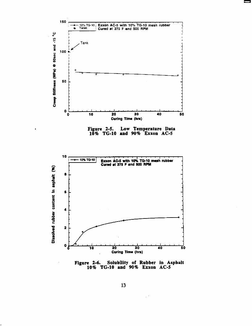
Aging Rate
Figures 2-26, 2-27, and 2-28, representing various asphalt-rubber blends aged at the three
POV-temperatures; 190, 200, and 210T, show that the aging rate, the slope of a carbonyl area
versus time plot, increases, and thus becomes worse, with the addition of rubber. The mount
of the increase in aging rate is apparently not a function of the rubber concentration. .Figure 2-29
shows that the aging rate at 140°F also increases with the addition of rubber, with the aging rate
increasing with increasing rubber content.
The aging rate when plotted versus the inverse of the absolute aging temperature, lrT,
yields an activation energy based on aging rate. Figure 2-30 shows that the activation energies
(magnitude of the slope of the line), as predicted by the POV-aged data, decrease with the addition
of rubber. The decrease appears to not be function of the rubber concentration. Additionally,
Figure 2-30 shows that the activation energies obtained from the'POV-data predict a 140°F aging
rate that is much higher than the 140°F aging rate that was actually obtained. An in-depth analysis
of numerous asphalts and asphalt-rubber blends is required to verify this finding.
Hardening Rate
Figure 2-31,2-32, and 2-33, representing various asphalt-rubber blends aged at the three
POV-temperatms- 190,200, and 21O"F, show that the hardening rate, the slope in a plot of log
q* versus time, generally decreases with the addition of rubber and thus, the rubber is beneficial
at the elevated temperatures of the POV. Figure 2-34 shows that the hardening rate activation
energies, the slope of a log (hardening rate) versus the inverse of the aging temperamre, I/", are
lowered by the addition of rubber. Additionally, Figure 2-34 shows that the activation energies
obtained from the POV-data predict a 140°F hardening rate that is much higher than the 140°F
hardening rate that was acidly obtained. The activation energies of Figure 2-34 also indicate
that, at low temperature, the hardening rate of the asphalt rubber binder will be larger than the
27


1 0 EXXAC10,TK 1 EXXON AC-10 AND BLENDS 5/95, EXX AGIO. TG -408. TK 1 10/90. EXX AC-10, TG -408, TK
200 OF DATA
A 5/95. EXX AC-10, RS -40, TK t 10190. EXX AC-10. RS -40, TK + EXX AC-10
' 0 4
. 10/90. EXX AC-10. TG -408 Z 5/95. EXX AC-10. TG -408
i A . 5/95. EXX AC-10. RS -40 - - -P . . 10/90. EXX AC-10. RS -40
, , O, ,
a 1.2 POV-Aged at 200 OF x 0 0 -I
2 1 with Atmospheric Atr v a I vn
H : 0 d 9 / '.A
t t " . y = 0.927 + o.woB2x Rx 0.9
Blends Cured at 375 OF and 500 rpm . . . . . y 0.7944 + 0.03915~ R r 0.
........ ~ y 0.956 + 0.03383~ Rr 0. for 12 hours under N,
TIME (DAYS) "
2.5
2
Figure 2-27. Aging Rates of Exxon AC-10 and Blends at 200'F
0 FlNA AG-10, TK YOS. ANA AC-10, TO -408, TK 10190. ANA AC10. TG - 4 0 8 , T)c
A &'E. FlNA AG-10, RS -40, TK V 10190, FlNA AC-10, RS -40, TK
FlNA AGIO 4 - YOS, ANA AG10. TG -408 - t - 10/90. FlNA AC-10, TO -408 ~-A--SiQ!5,FlNAAGlO,RS-40 .-."" 1WW. RNA AG10. RS -40
POV-Aged at 21 0 9 wlth Atmospheric Air
FINA AC-10 AND BLENDS 210 @F DATA
+ 0.06642x R= 0. i5 - - y I 0.006 + 0.01018~ R= 0.
" - y = OS321 + 0.0747h R= 0.
Blends cured at 375 OF and 500 rpm . . . . - y I 0.031 1 + 0.07003x R= 0.
for 12 hours under N, . . . . . . . . - y = 0.009s + 0.07377~ R= 0.
0 ~ " " " " ' ~ " " " " ' ~ 0 5 10 15 20
TIME (DAYS)
Figure .2-28. Aging Rates of Fina AClO and Blends at 210 'F
29
EXXON AC-5 AND BLENDS " . y = 0.6634 + 0.001317~ R= 0.9882
140 OF DATA
1.2 L - ' l - , , , I , , , , , , , , , , , , , . v = 0.6873 + 0.001912~ R= 0.9454 1
1- - y = 0.7167 + 0.002087~ R= 0.9722
1.1 - .
1 I- - a a a
y = 0.6979 +
. y = 0 7007 4
6 B
5 0.7 c IJ = lntial Jump Region 0
ENV-Aged at 140 OF wlth Atmospheric Air
V 10190. EXX AC-5. RS 4. TK 0 EXXAG5.W
Yes. EXX AC-5. TG JOB. W E 10180. E X X AC-5. TO -408, W C Sh% WX AG5. RS -10. W + IW. EXX G 5 . RS 40, U
4- . EXX AG5
0.5 Blends cured at 375 OF and 500 rpm - -e . - sms .D txG5 .x -1OB +..-1W.E%XAG5.TGJOB d -5/95.w(Ac5.Rs-40 for 12 hours under N,
I , , I I I 1 1 . 1 I I 1 " - 1 W . E = ~ 5 * R S J O 0.4 50 100 200 250 TIME (DAYS)
Figure 2-29. Aging Rates of Exxon AC-5 and Blends at 140'F
Exxon AG5 and Bknda
0.1 I " " I " " I " " I " " .
a, 4 - m , T G 4 0 + WON AGS
-e *101Po,TG40 LI
s *
; t 0.01
"..o" 4- -W, 1m, R S 4 0 Rs 40 '*q*.% EXXONAGS. l@F -
3 . 5 m , TG 40.1@F - A m, Rs40.1409 C
1 m , T G 4 0 . l W F for 12 hours under N, * - Blendscuredat3f5"Fandsoorpm
POV-AGED at 190,200, and 2 1 0 9 ' 10190. Rs 4 0 , 140°F
si
- C
. and ENVROOM-AOED at 140 "F under Air ENV-Room
- - -y="Oq4311x)R=O.983 $. 3 - - y r l . W ' M + 6 2 4 ~ ) F l r 0 . 0 1 6 I
- - -y=23.93*.y-2#l*r)FlrO.9965 €
U 0
z - y = 5.764046 O q a 6 2 X ) R= 0.9904 140.F Data
0)
A . . . . . . . . . y = 80.27 ' Oq-2612X) R= 0.9584 0
0 . 0 0 1 ~ " " " " " " " " " ' " ' " 0.0026 0.0027 0.0028 0.0029 0.003 0.0031
lnomp (In<)
Figure 2-30. Aging Rate Kinetics Plot of Exxon AC-5 and Blends
30

- y I 3214 ' HO.1479X) RP 0.9929 FlNA AC-10 AND BLENDS - - y = 6 7 3 2 ' ~ 0 . 1 4 1 1 X ) R ~ 0 . 9 9 3 8 100 OF DATA
1
f" Tank Samples
10' (r
- POV-AGED AT 190 OF . with Atmospheric Air
l o l o " " " "
5
loC i
Blends cured at 375 OF and 500 rpm for 12 hours under N2
5/95, FlNA AC-10. TG 4, TK 1 10/90. FlNA AC-10. TG -40, TK I 5/95, FlNA AC-10, RS -40. TK 1w90, FlNA AC-10. RS -40, TK * FlNA AG10,lgoF
"-8 .W5, FlNA AC-10, TG -40 - + - 10190, FlNA AGIO, TO 4 0 ~.a.-5195.FINAAGlO.RS-40 . . .+.. .
10 15 20
Figure 2-31. Hardening Rates of Fina AC-10 and Blends at lW°F
L L
W(ON AC-5 AND BLENDS 200 'F DATA "
Blends cured at 375 OF and 500 for 12 hours under N,
-
lo* t - lank*-
y = 967.7 * #O.l247x) R= 0.095
- -yr2795'#0.1~)R=0.9907
- - -y~90o'#O.llx)R=0.9901
'= c ""_ y=l6lO'#O.llS6~)R=0.9983
- - -y=san.#O.1~)FbO.9979
1 ~ ~ ~ ~ " ~ " " ~ ~ " " " ~ ' I 10 15 20
Time (Days)
Figure 2-32. Hardening Rates of Exxon AC-5 and Blends at 200'F
31

EXXON AC-10 AND BLENDS 210 OF DATA
l o s t , I , I I , , , , I , , 0 EXX AC-10, TK 5/95. EXX AC-10. TG -40. TK
A 5/95. EXX AC-10. RS -40. TK 0 10/90, EXX AC-10. TG -40. TK
10190. EXX AC-10, RS -40, TK EXXON AC-10 - 1 . 5/95. EXX AC-10. TG -40
- . 10190. EXX AGIO TG -40
10' C 5/95. EXX AC-10 RS -40 1 -V 10/90. EXX AC-10. RS -40
with Atmospheric Air
I 0 ' L 1 0, 0
Blends cured at 375 OF and 500 rpm Tank Samples for 12 hours under N,
- - y = 1492 e"(O.1844X) R= 0.9412
- . y = 1.87- H0.126X) R= 0 . W 7
- - . y = 1.4- * wO.1443X) Rr 0.9876 . . . . - y = 1.1 1 7 W wO.lsaX) R= 0.9759
. . . . . . . . . y = 12840+04 ' e"(0.1273x) R= 0.8876
5 10 15 20 ~ " ~ " " ~ " " " " '
Tlmo (Days)
Figure 2-33. Hardening Rates of Exxon AC-10 and Blends at 21O'F
1 1 EXXAGQ.I~ODFDATA . M, EXX AC-5, TG -4OB.140 OF DATA 10190. EXX A m , TG 408,140 OF DATb W. EXX AGS. RS -40,140 OF DATA 1 W . w( AC-5. RS -40,140 OF DATA
Blends cured at 375 OF and rpm for 12 hours under N, - y = 1 ~ 1 0 ' ~ - a 3 o l x ) F l r 0 . 9 7 8 2
- ~ y r a . 1 @ 7 " . Y ~ ~ R - 0 ~ 1
- - -yr6X)1"~um~R=O0.991l 4 . Figure ' 2-34. Hardening Rate Kinetics Plot
of Exxon AC-5 and Blends
32

corresponding base asphalt. This prediction from the POV elevated-temperature data is
contradicted by the 140°F ENV-Room data in Figure 2-35, 2-36, and 2-37, which represent the
3 base asphalts; Fina AC-10, Exon AC-5, and Exxon AC-10 aged at 140°F. Figures 2-35, 2-36,
and 2-37 show that the hardening rate (slope) at 140°F is not a function of rubber content. The
data that was in the initial jump region is labeled with U in the figures. The initial jump region
is defined as the time before In q* is linear with time. An in-depth analysis of numerous asphalt
and asphalt-rubber blends is required to verify this finding.
Although an asphalt-rubber binder hardens as fast or faster than its base asphalt at 140T,
this hardening may not be as detrimental to the asphalt-rubber binder as it is to the base asphalt.
The hardening is not as detrimental because the rate of change of elasticity of the binder, as
meaSured by delta, 6, (A mamial with 6=W is perfectly viscous, whereas a material with 6=Oo
is perfectly elastic.) with aging time is more negative for the asphalt-rubber binder than the base
asphalt. This is shown in Figures 2-38, 2-39, and 2-40, representing the 3 base asphalts; Fina
AC-10, Exxon AC-5, and Exxon AC-10 aged at 14O"F, and implies that for the Same amount of
aging time, the elasticity of an asphalt-rubber binder increases more than the elasticity of its base
asphalt.
Additionally, several asphalts and cured asphalt-rubber blends are currently being aged in
the ENV mom and will be POV aged as well. These samples will be analyzed to determine the
effects of rubber amtent (10 and 20%) ind high shear rate of curing on aging properties. These
samples include:
&ph&s: (Total of 4)
Fina AC-10
Exxon AC-5
Exxon AC-10
Fina Demex Resin -: (Total of 8, 4 asphalts x 2 blends)
2 blends of each asphalt:
with 10% TG-40 Buff
with 20% TG-40 Buff
33

FlNA AC-10 AND BLENDS
ENVROOM-AGED AT 140 OF UNDER AIR
4
1
0 - IJ = lnitlal Jump Reglon I 10' C C X - I
€ 0 h FINA AC-IO, TK
~ 5/10, FINA AC-10. TG -40. TK Blends cured at 375 OF and 500 rpm A as, FINA A G I O , RS
TK for 12 hours under N, 10/90. FlNA AG10, RS -40, TK 10/90. FINA A G I O . TG -40, TK ~
0 FlNA AGIO. IJ
0 10/90, FlNA AG10. TG 40, IJ y = 5258 W'(0.009327~) R= 0.9953 0 995, FlNA AC-10. TG -40. IJ
1 oJ - - y I 8581 W'(O.oosS58~) R= 03977
J
W O N AGS AND BLENDS
I , , , , I , , , ,
ENVROOM-aged at 140 9 wlthMmoephericAir
Blends anedat375oFMd5oorpm for 12 hours under N,
" - y = 1693 ~ 0 . W 6 3 4 5 ~ ) R= 0.9948
......._ - y = 9316 r(O.OO7ODBx) b 0.0884
10' 0 50 100 150 200 250
Time (Days)
Figure 2-36. Hardening Rates of Exxon AC-5 and Blends at 140'F
34

ENVROOM-aged at 140 OF with Atmospheric Air EXXON AC-10 AND BLENDS
I go; - - P 6
IJ = lnltlal Jump Reglon !
I 0 EXXAC-10 TK
IJ = lnltlal Jump Reglon ! -1 2 0 EXXAC-IO TK
5/95, EXXAC-10. TG 40, TK ' A 5/95. EXX AGIO. RS -40, TK 10BO. EXX AC-10. TG -40, TK
10B0, EXX AGIO. RS 40 , TK y = 2824 q0.005489~) R= 0.9928 1 0 EXX AG10.1J
103 0 5/95. EXX AGIO, TG -40, IJ
A m. w( AC-10. RS -40, IJ 0 10190. EXX AC-10, RS -40. U
- . y = 1.086e+04 O'(0.00763~) R r 0.9938 * AC1O, TG
- - . y L 1.23- O'(o.oo6418X) R= 0.093 - w( A G ~ ~
.~ ~
0 50 100 150 200 250 Time (Dayr)
Figure 2-37. Hardening Rates of Exxon AC-10 and Blends at 140'F
- y = 8Q.22 + -0.02602~ R= 0.0916
RNA AG10 AND BLENDS - - y = 03252 + -0.01308~ R= 0.8802
s o 4 , , , , , , , , , I , , , ,;I 0.964
.... "." y I 78.31 + 0.05101~ Ra, 0.9886
85 ENVROOM-aged at 140 OF
wlth At~nospheric Air 0
" 4 'I
Blends cured at 375 OF and for 12 hours under
- -A- :<\ I
Q *+ 0 FlNA AC-10. TK
>> A S'B5. f lNA AC-10, RS -40. TK
r . .... 0 Q....
5%. FlNA AC-10. TG -40, TK "9 A lOM, FlNA AC-10. TG -40. TK . ....
75 - . * t.".... 1WO. FlNA AC-10, RS -40. TK + FlNA A G l O
- .1WO. FlNA AC-10. TG -40
---+..- 1WO. FlNAAC-10. RS -40
. $.." . P 4 . W, FlNA AC-10, TO -40 . ... . .-. * . 2 - v . . d- . yo5. FlNA AC-10. RS -40 . .... . .. . " . O
70 l . . 3 , l t o , . l , , , ,
0 50 100 150 200 Tim. (Dayr)
Figure 2-38. Change' in Delta with Aging for Fina AC-10 anb Blends
35

EXXON AC-5 AND BLENDS Blends cured at 375 OF and 500 rpm
for 12 hours under N2
Figure 2-39. Change in Delta with Aging - y = 89.69 + -0.01 115x Rr 0.9886
- - y = 82.81 + -0.0352~ R= 0.9862
UO(ON AC-10 AND BLENDS " - y = 77.91 + -0.03322~ R= 0.9763
80 , , , , , , , , , I . I , I ,, "X R= 0.979 - " y L 7729 + -0.0: 7 6 6 ~ R= 0.9771
ENVROOM-AGED AT 140 OF 85 I- UNDER AIR 0 Do(Ac10,TK
5/95, Do( AC-10, TG 40, TK
Blends at OF rpm lQlS0, EXX AC-10, TG 4 0 , TK A 5/95, Do( AC-10, RS 40. TK
10190, Do( AG10, RS -40, TK for 12 hours u W r N2 % \ -8- w( AC-10
4 - 5/95. Do( AG10, TO -40 - - 10/90, Do( AC-10, TO 40 4- - 5/95, Do( AC-10, RS 4 0 ---+.-. 10190, Do( AG10, RS -40
80 - 49, " L
* -:*- "
0 0 v.: ' 0,
75 - * * - q....v ' ' - "... 0' '0, '
0.- .... v -*..... 0 ' ' .-. - 0
v "0.. ... '0. ' v.. .". - ' 0 ,
70 l , , , . l . . , , l , , , , ~ " , , , , "0 ....p b
0 so 100 150 x 200 250 Tim (Days)
Figure 2-40. Change in Delta with Aging for Exxon AC-10 and Blends
36

DEVELOPMENT OF MICRODUCTILITY TEST FOR USE WITH ASPHALT-RUBBER BINDERS
The ductili~ of an asphalt-rubber binder is defined a~ the distance to which it will elongate
before breaking when two ends of a specified geometry are pukd apart at a defined and
temperature. It is a physical test that can be used to help characterize the performance properties
of a binder. Although the significance of ductility for unaged binders is highly debatable, changes
in ductility over a binder's service life appear to correlate with overall roadway perf~rmance
(Hveem et al., 1963).
Several methods are! currently being used to test the ductility of a binder. The most widely
used ductility method is the method specified in ASTM Dl 13. The drawback to the current
methods is that they require large sample sizes. For example, ASTM Dl 13 requires a 1 .O cm
thick "dogbone" briquette that is over 7.0 cm long. The total sample mass is close to 10 g. This
method is particularly unsuitable when smaU mounts of material are available, as is the case with
laboratory aged samples or binder recovered from pavement samples. Another widely used
method is the SHRP direct tension method as specified in AASHTO TP3. The direct tension test
measures the low-temperature fracture properties of the asphalt binder. A dogbone-shaped
specimen is tested at a constant rate of elongation of 1.0 mm/min at a specified temperature until
it fractures. The stress and strain at failure are calculated using the initial cross-sectional area (A)
and effective gauge length (LJ of the specimen, the load at failure (PJ, and elongation at failure
(A L& The Texas A&M Center for Asphalt and Materials Chemistry plans to acquire a S H R P direct tension apparatus when sufficient funds are available.
Currently, ductility is b e i n g ~ m d witkthe micruductility instrument. This instrument
and a micro-ductility test were developed in the 1960s by Hveem et al. (1963) to measure the
ductility of a small amount of these materials. The apparatus and method developed by Hveem
et al. a d a modified version of their method are described below.
37

Experimental Method (Hveem et al.)
The apparatus and procedure used for the microductility experiment was developed in
November, 1962 by California's Division of Highways. This test method (Calif. 349-A) is
designed to measure ductility of a small sample (0.05 g) of bituminous material at 77 +/- 1°F.
Test specimens are liquified on a hot plate, thoroughly stirred, and then placed inside a two part
brass mold of cylindrical geometry. This mold is allowed to cool to ambient conditions for 15
minutes. The mold forms a 0.069 inch diameter cylinder of asphalt binder and grips it at both
ends. The mold is placed into a ductility machine designed to pull the mold halves apart along
their axis. After the machine and mold have been immersed in a water bath for 10 minutes, the
mold is placed into a holder. One end of the holder is attached to a motor. The motor is then
activated and pulls the sample apart at a constant rate of 0.5 cm/min. As the test progresses, the
original cylinder of asphalt-rubber binder stretches into a very thin thread and eventually breaks.
The separation distance of the two mold halves is measured in millimeters and reported as the
ductility. In addition to being able to measure the ductility using a Small sample size,
approximately a7596 of the specimen can be m d at the donclusion of the test, if necessary.
The biggest limitation of the equipment used by the Calif. 349-A method is the inability
to measure the force required to generate the constant strain rate. Such force information could
be used to create a stress-strain m e for the sample. Another limitation is the small size of the
asphalt cylinder formed inside the mold. Aged binders will often fail before the molds separate
a significant distance.
Modified Experimental Method As described above, one limitation of the original method is the small size of the asphalt
cylinder. To minimize this problem, molds with larger diameter holes were fabricated. The
largest of the hole sizes is approximately twice that of the original mold. This only increases the sample mass required by a factor of four, so the apparatus is still capable of measuring the
ductility of a material using m u c h k s than 1 g of sample. An additional benefit of using a larger
hole size is the ability to perform the test at lower temperatures, where ductility is generally
greatly reduced.
38

Application
The modified microductility apparatus is currently being used to study bituminous materials
without any addition of rubber. It is hoped that this test method will also yield useful information
concerning asphalt-rubber binders. Because this method accommodates samples at relatively low
temperatures (35-45"F), it may provide additional support for the low temperature benefits of
rubber-modified binders. This test will be performed on several asphalt-rubber binders and the
measurements compared to existing physical property data.
39
CHAPTER 3
EVALUATE MIXTURE CHARACTERISTICS
This portion of the project is a laboratory study to evaluate the modified binders in asphalt
concrete mixtures. The two primary objectives are (1) to assess the expected performance of
mixtures that will be placed in the engineering development and demonstration phases of the
research, and (2) to define the construction procedures to be used.
EVALUATE COMPACTION CHARACTERISTICS OF MIXTURES
Compactibility of crumb rubber modified asphaltic concrete mixtures has been thought to
be a serious problem based on field experience. The crumb rubber seems to interfere with
compaction such that adequate field densities are not obtained thus contributing to early failure
of the pavement. This problem has been combatted with the development of mixture design
procedum such as that used by the Texas Department of Transportation (TxDOT). It is thought
that with a gapgraded aggregate, more void space is available to accommodate the crumb rubber
particles without i n t e d h g with fidd densities. Limited field experience supports the validity
of this type of design for crumb rubber mixtwes. Crumb rubber asphaltic mixtures weze designed and fabricated in the laboratoxy according
to a mixture design procedure developed by the Texas Department of Transportation for crumb
rubber mixtures. This design procedure was developed to ensure that the load is carried by the
stone skeleton and the void space is filled with the crumb rubber modifier (CRM) and binder.
An experiment was designed to meet the following objectives: 0 Determine the effect of CRM concentration on the compactibility of CRM
asphaltic concrete mixtures.
0 Determine the effect of CRM size and/or gradation on the compactibility
of CRM asphaltic concrete mixtures.
0 Determine the effect of binder curing time on the compactibiity of
40

asphaltic concrete mixtures.
0 Evaluate the effectiveness of the mixture design procedure. 0 Evaluate the expected permanent deformation characteristics.
The experiment was designed to incorporate the following variables:
(1) CRM Particle Size (Gradation) 0 Top size particle passing #10 sieve
0 Top size particle passing #40 sieve
0 Top size particle passing #80 sieve
(2) Binder Curing Time (low shear blending) 1 hour at 350°F
6 hours at 350°F
(3) CRM Concentration (percent by weight of asphalt cement)
Opercent 0 10 percent
0 18 percent (concentration typically used by DOTS)
25percent
The US Army Corps of Engineers gyratory p r d u r e (ASTM 3387) was used to evaluate
the compaction characteristics of the materials in this subtask. This is essentially an instrumented
version of the Texas gyratory compactor and can be used to describe the progression of material
changes throughout the compaction process. The procedure is designed to address both
compactibility and performance-dated issues of the mix designs, such as rutting.
All of the samples for this experiment have been tested and preliminary data analysis is
complete. A discussion of the preliminary analysis follows. A unique feature of the Corps of Engineers gyratory test machine (GTM) is its ability to
record the density of the sample with each revolution of the compactor. Unit weight per GTM
re~olution is shown in Figures 3-1,3-2 and 3-3 for the 1-hour and &hour binder curing times for
the #lo, #40, and #80 C R M s , &pectively. preliminary analysis of the data indicates very little
measured difference between the 1 and 6-hour CUES for any of the CRM si=. There also
41

Unit Weight, pcf 150
- 1 -hour Cure 140. . . + .6-hour Cure. . . . . . . . . . . . . . . . . . . . . . . . . . . . . . . . .
. . .........................................................
0 20 40 60 80 100 120 140 160 180 200 220 240 GTM Revolution
Figure 3-1. Density Versus GTM Revolution for CRM Asphaltic Mixtures Prepared with Binders Containing 410 Mesh CRM
Unit Weight, pcf
GT.M; Revolution Figure 3-2. Density Versus GTM Revolution for CRM Asphaltic Mixtures Prepared
with Bindels Containing 440 Mesh CRM
42

Unit Weight, pcf 150 I
i
....................................................................
0 20 40 60 80 100 120 140 160 180 200 220 240 GTM Revolution
Figure 3-3. Density Versus GTM Revolution for CRM Asphaltic Mixtures Prepared with Binders Containing 480 Mesh CRM
appears to be little difference behueen 4 0 , #a, and -#80 mesh C R M s
The gyratorly compactibility index (GCI) is an indicator of the compactibility of the mix.
The closer this index approaches unity, the easier the mix is to compact. It is calculated as the
ratio of the unit mass (total mix) at 30 revolutions of the GTM to the unit mass (total mix) at 60
revolutions of the GTM. The GCI data is presented in Figures 3-4,3-5, and 3-6. The effect of CRM particle size on the GCI is presented in Figure 3-4 and based on these
data, all of the mixtures including the control mix (with no CRM) were very easy to compact.
The effect of CRM concentration on the GCI is shown in Figure 3-5. Surprisingly enough, the
mixture with the binder &ntaining 25 percent CRM (by weight of the asphalt cement) was no
more difficult to compact than the asphaltic mixture with no CRM. The effect of binder curing
43

Compactibility Index 1
0.8
0.6
0.4
0.2
0 Control -#lo mesh -#40 mesh 480 mesh
CRM Particle Size
44

Cornpactibility Index 1
0.8
0.6
0.4
0.2
. o
. . . . . . . . . . .
. . . . . . . . . . . . .
. . . . . . . . . . . . .
.... ..........
. . . . . . . . .
..........
. ; . ~ i . . . . .
I -hour Cure 1 [7 6-hour Cure ...
.." ................ . 1.. - . . * . . . .
4 1 0 mesh -#40 mesh 480 m e s h
CRM Particle Size
Figure 36. Ef'fect of Binder Curing T i e on Gyratory Compactibility Index (GCI)
time on compactibzty can be seen in Figure 3-6 which indicates that no difference was detected
in compactibiiity between 1-hour and &hour mixes.
The gyratory stability index (GSI) is calcuhtd as the ratio of the maximum gyratory angle
to the minimum gyratory angle. A GSI in excess of unity indicates a progressive increase in
plasticity during densification. An in- in this index indicates an excessive bitumen content
for the compaction pressm employed and foretells instabiity of the bituminous mixture for the
loading employed. A mix GSI in excess of unity atso indicates the lilrelihood of the mixture to
permanently deform. The effect of CRM particle size on GSI is shown in Figure 3-7. All of
these- mixtures have acceptable GSIs. The effect of CRM ConcQItratiOn on GSI is shown in Figure
3-8 which indicates instability in the mixture containing 25 percent CRM in the binder. The
binder curing time (Figure 3-9) does not appear to affect the GSI.
45

Gyratory Stability Index 1.2 !
1 1 I
1 , I
. . . . . . . . . . . . . . . . . . . . . . . . . . . . . .
. . . . . . . . . . . . . . . . . . . .
.......... . . . . . . . - . . . . . . . . . . .
.”....... .......... ..........
Control -#lo mesh 4 4 0 mesh -#80 mesh
CRM Particle Size
Figure 3-7. Effect of CRM Particle S i on Gyratory Stability Index (GSI)
Gyratory Stability Index 1.2
Figure 3-8. Effect of CRM Concentration on Gyratory Stability Index (GSI)
46

Gyratory Stability Index 1.2
1
0.8
0.6
0.4
0.2
‘0 -#lo mesh 440 mesh 4 8 0 mesh
CRM Particle Size
Figure 3-9. Effect of Binder Curing Time on Gyratory Stability Index (GSI)
Based on the results presented herein, the GTM did not measure adverse compactibility
properties of the mixtures tested. Howcr, the GTM measurements are made during the
compaction process (while the sample is under load). When the load was removed from the
sample, some significant changes were observed. The samples which were compacted containing
the -#lo mesh rubber ded significantly within the first 24 hours aftcr compaction. One sample
made with the 410 CRM wen disintegrated upon removing it from the mold. Sample heights
were taken at the end of the compaction pnxxss and again 24 hours aftcr removing them from the
mold. Ths data a~ shown in Figure 3-10. Note that the 410 CRM mixture was significantly
taller 24 hours after extrusion. Intuitively, this characteristic would be highly undesirable in a
field mixture. It indicates that CRM mixtures may m y compact in the field under the weight
of the roller; however, when the roller is removed the density may become unacceptable.
47

Sample Height, inches 3.5
3
2.5
2
1.5
1
0.5
0
. . . . . . . . . . . . . . . . . . . . . . . . _ . . - . . . . . , .
n
Control 4 1 0 mesh 440 mesh 4 8 0 mesh
CRM Particle Size
Flgure 3-10. Sample Height Before Extrusion from the Mold and 24-Houw After Extrusion
Inthepsst,ithasbcenstandardpracticeto~owcRMasphalticconcntcsamplestocool in the mold to prevent the sample from swelling; however, this practice may be deceptive. It
may be better practice to extrude the sample aftcr molding and then measure if swelling occurs.
If swelling docs occur, then acljustments to the mixture design (in particular, the aggregate - gradation) should be made.
The following are some preliminary conclusions based on this effort:
. T h e TXDO" mixture design procedure used in this study, in general sezms to be acceptable for the design of CRM asphaltic mixtures.
0 CRM mixtures designed according to the TxDOT mixture designed
procedure appear to be resistant to permanent deformation, with the
48

exception of the mixture which contained a large concentration of CRM
(25 %).
The CRM binder curing times evaluated in this study did not affect
compactibility or permanent deformation characteristics of the asphaltic
concrete mixtures.
CRM pamcle size is the main variable evaluated in this study which affects
its compactibility, based on measurements of sample heights taken after
extrusion from the mold. CRM particle size of 4 0 or greater is of
greatest concern. While it may be possible to design a mix to accommodate
CRM of this size, the mixture design in this study was not adequate.
EVALUATE DEFORMATION AND FAILURE OF, COMPACTED MMTURES
In the compaction study, a methodology for designing good mixtures was verified. In
Subtask 2.3, the methodology is being applied to design and compact mixtures having different
asphalts and binder preparation methods. These materials will be aged and tested for deformation
and failure using three test methods: (1) "nondestructive" sinusoidal frequency sweeps (fully
reversed tension-compression), (2) creep and recovery, and (3) tensile strength to failure. A
summary of the experiment plan is shown below.
49

Preparation of binder samples to be tested for this subtask is complete. Compacted
samples will be prepared using six different asphalt cements combined with 18 95 -#80 CRM cured
under two different conditions for a total of 12 binders. The six asphalt cements to be used in the
experiment are as follows:
Diamond Shamrock Resin,
Fina Resin,
Fina AC-10,
Fina AC-5,
Exxon AC-5,
Exxon AC-10.
Two curing conditions wen used for preparation of the binders:
375"F, 1550 rpm, 6 hours, and
350"F, 500 rpm, 1 hour.
All of these twelve binders have been prcpared. Aggregate has also been prepared for preparation
of the compacted samples and compaction of samples is ongoing.
50

CHAPTER 4
ADHESION TEST PROPERTIES
The strength of an asphalt-aggregate composite mix and its performance under varying
loads and environmental conditions are key factors in determining pavement lifetimes. These
factors strongly depend on the cohesive properties of the asphalt constituent and the adhesive
properties at the asphalt-aggregate interface (Labib, 1992).
The work of cohesion is the work required to create two interfaces from one phase (see
Figure 4-1):
AG' = 2y, (4.1)
where AG' is the Gibbs free energy of cohesion, and y l is the surface energy of phase 1. The
work of adhesion is what is needed to create two interfaces from two phases in contact (see Figure
4-2) :
AG'12 = Y l + Y2- Y12 (4.2)
where AG'12 is the Gibbs free energy of adhesion and y12 is the interfacial surface energy of phase
1 and phase 2.
The cohesive and adhesive bonding interactions in asphalt-aggregate systems arise mainly
from two effects: (1) the Lifshitz-van der Waals interactions of electron shells of neighboring
molecules and (2) the acid-base interactions betwem constituent molecules (Good and van Oss,
1992). The acid-base interactions are generally dominant for asphalt-aggregate composites and
are particularly critical in establishing strong adhesive bonds as well as bonds that are resistant to
water enhanced stripping (Labib 1992). The acid-base interaction term is further partitioned into
a kwis acid parameter and Lewis base parameter. Thus, three parameters must be determined
to calculate the surface energy of the material: Lifshitz-van der Waals, Lewis acid, and Lewis
base. The surface energies of the materials, the asphalt and aggregate, are used to calculate the
work of cohesion and the work of adhesion. It should be noted that the Lifshitz-van der Waals
force is present in all molecules, but acid-base interaction are not. In fact, the acid-base
interactions will be the key in determining the compatibility of asphalts and aggregates,
:. , I
. . .
51

1
v L
1
1
1
Vacuum
Figure 4-1. Work of Cohesion
2
Figure
1
4-3. Work of Adhesion
52

The usefulness in being able to calculate the work of cohesion and adhesion by measuring
the surface energies of asphalts and aggregates are threefold: (1) The mechanical work required
to crack an asphalt-aggregate interface can be predicted. This theoretical work of adhesion would
correspond to a fracture test measured below the brittle-ductile transition temperature. (2)
Numerous crack propagation models exist; but, these models require difficult experiments to
determine the parameters. It can be shown that these parameters are functions of the surface
energies of the materials. By measuring the surface energies of asphalts and aggregates, these
parameters can be calculated. (3) Asphalt-aggregate systems can be evaluated for the propensity
to be water susceptible. Suitable asphalts may be found for the so-called "stripping aggregates."
The focus of this portion of the project is establishing the framework for predicting adhesion and
cohesion in asphalt-aggregate systems. The main goals of this investigation are: (1) to develop
test methods that predict adhesion and cohesion in asphalvasphalt-rubber and aggregate systems,
(2) develop test methods predicting adhesion and cohesion in asphalvasphalt-rubber and
aggregate systems in a water environment, and (3) to use the test methods to evaluate
asphaltlasphalt-rubber and aggregate mixes.
ADHESION TESTS
Wilhelmy Plate Method
The Wilhelmy plate method (Wilhelmy, 1863) is an established technique for measuring
contact angles of liquidhlid systems and is being used in this study. The contact angle is
determined by measuring the change in force during immersion and emersion cycles (see Figure
4-3):
AF = py a s e (4.3)
where AF is the change in force; p is the perimeter of the plane; y is the surface tension of the
liquid; and 8 is the contact angle between the solid and liquid measured through the liquid.
The apparatus consists of three main components (see Figure 4-4): the Cahn C2000 balance for measuring the force; the moveable platform to advance and recede the liquid;
53

(a) before plate contacts with liquid
F=ppVpg
Liquid
Liquid
Figure 4-3. Dynamic Wilhelmy Plate Method Force Balance
54

I t- Cahn C2000 balance
step motor &
. I computer
data acquisition & control
-
-
shielding case
Figure 4-4. Wilhelmy Plate Apparatus

and a computer for data acquisition and control. Glass plates are coated with asphalt to produce
a smooth solid surface. The contact angle of four fluids (water, glycerol, ethylene glycol, and
formamide) are measured against the asphalt coated glass plate. From the advancing and receding
contact angle measurements of two fluids, the three parameters of the surface energy can be
determined. The two remaining fluids are used to verify the results.
An inherent problem with the Wilhelmy plate technique is contact angle hysteresis.
Hysteresis is the difference between the advancing contact angle and the receding contact angle.
It is believed that for heterogeneous materials that the hysteresis effect can be explained. While
the liquid "sticks" on the high energy acid-base regions and only wets the Lifshitz-van der Waals
regions. Therefore, the acid-base interactions are negligible while advancing. While receding,
the liquid preferentially wets the high energy regiops; the receding contact angles are a measure
of the total surface energy.
Figure 4-5 is an example of a typical set of experimental results. The lower straight-line
region cOrreSpOndS to the advancing angle while the uppa straight-line corresponds to the receding
angle. For each experiment, a total of 5 advancing and d i g cycles are measured. As can be
seen from Figure 4-5, the reproducibility for a single plate is quite good.
A total of 19 asphalts haw been chmcmkd using the Wilhelmy plate method (see Table
4-1). Figure 4-6 is a graphical representation of the two surface energy Components: YLw is the Lifshitz-van dm Waals force while ym is the acid- interactions. All of the asphalts exhibit
a wide range of values.
Gas Adsorption
The aggregates pose a more difficult problem than the asphalts. Since a smooth surface
cannot be made from the -, gas adsorption must be utilized (see Figure 4-7). A total of
four gases are needed for this process; three to characterize each aggregate with the fourth being
used to check the results. The gases used are hexane, water, methyl propyl ketone, and
chloroform. I . 4.
six aggregates have been characterized with one being separated into 7 size gradations
56

LL 0
350
300
250
200
150
100
50
0 -0.4 -0.2 0 0.2 0.4 0.6 0.8
Depth (cm)
Figure 4-5. Example Experimental Results
60
* 0)
E W
0
5 30
20
10 a u)
" " Material
Figure 4-6. Surface Energy of Various Asphalts
57

.
Figure 4-7. Gas Adsorption Experimental Apparatus
58

(see Table 4-2). Figure 4-8 represents the two components of the surface energy. Both
components are much larger for the aggregates than for the asphalts.
Adhesion and Cohesion
From the measured surface energies, the work of cohesion and the work of adhesion can
be calculated. The work of cohesion for various asphalts in a vacuum and in water can be Seen
in Figure 4-9. For less polar asphalts (having small acid-base parameters), water increases the
work of cohesion.
If the work of adhesion is greater than the work of cohesion, fracture should occur in the
asphalt. If the work of the adhesion is less than the work of cohesion, fracture should occur at
the asphalt-aggregate interface. Two aggregates were analyzed with various asphalts in a vacuum.
According to Figures 4-10 and 4-1 1, fracture should occur in the asphalt binder. Figure 4-12 is
a comparison of the two aggregates in a vacuum. Both JGlla and JG21 have similar works of
adhesion.
WATER SUSCEPTIBILITY TESTS
According to Figures 4-13 and 4-14, water will decrease the work of adhesion. For
aggregate JG1 la, some asphalts have the potential to strip (see Figure 4-15) since the work of
cohesion is greater than the work of adhesion. For aggregak JG21, virtually all the asphalts have
the potential to strip (see Figure 4-16). In Figure 4-17, the aggregates are compared by the work
of adhesion in water. The dts suggest that JG1 la is hettcr aggregate than JG21 for all asphalts.
Summary of Adhesion Tests
Using the work of adhesion and the work of Cohesion, the asphalt-aggregate systems can
be ranked according to their potential to water strip (see Table 4-3). These are presented from
highest to lowest with the acceptabie systems having a positive difference and the unacceptable
systems having 'a negative difference.
59

Table 4-1. Characterized Asphalts
Code
SHRP California Coastal AR 5000 ’ AAD-1 SHRP Wyornrng Sour AC- 10 ‘ AAB- 1
Description
AADN AAD-1 + 6% PE, Novophalt AAG-1 SHRP California Valley AR 4000
’ A A ” 1 West Texas Intermediate AC-20
Table 4-2. Characterized Aggregates
Code JG1 l a JG1 l b JG1 IC J t i l Id JG1 le JCil If J G W JG12 JG 13
60

200
150
100
50
n
Material
Figure 4-8. Surface Energy of Various Aggregates
100
50
0
Material
Figure 4-9. Work of Cohesion of Various Asphalts
61

250
200 n
E 100 B
50
0
Material
Figure 4-10. Work of Adhesion and Cohesion of Various Asphalts with Aggregate JGlla in Vacuum
200 n cy <- sj 150 E E Y
50
0
Material
62

n 250 (Y < E 3 200 E
I 150
v
a2 c Q,
100 r 0
50
E" n
JG21 Adhesive Work in Vacuum d
Material
Figure 4-12. Work of Adhesion for Various Asphalts and Aggregates in Vacuum
E o 150
Y
r Q)
c aa - p 100
P
)r
0
5 50
0
Figure 4-13. Work of Adhesion of Various Asphalts with Aggregate JGlla
63

n cv C
250
E 3 200 E
- 6 150 U
cn aa s p 100
P
r 0
2 50
- m h Y '
JG21 Adhes JG21 Adhes
mi a4 a4
? Work in Vacuum 3 Work in Water
Material
Figure 4-14. Work of Adhesion of Various Asphalts with Aggregate 5621
n
< E 3 E
c Y
150
100
50
0
l ~ l - l ~ l - l - l - l ~ l - l - l ~ l ~ l ~ l ~ l ~ l ~ l - l ~ l ~ . JG1 l a Adhesive Work in Water :m Cohesive Work in Water
Material
Figure 4-15. Work of Adhesion and Cohesion of Various Asphalts with Aggregate J G l l a in Water
64

150
0
Material
Figure 4-16. Work of Adhesion and Cohesion of Various Asphalts with Aggregate 5621 in Water
E JG11 a Adhesive Work in Water JG21 Adhesive Work in Water
E
Material
Figure 4-17. Work of Adhesion for Various Asphalts and Aggregates in Water
65

Table 4-3. Ranking of Asphalt Aggregate Systems
Acceptable JG1 la--=Sa JG1 la--EXS JG21--EXSa JGl la--EXlOa JGlla-AA"1 JGl la-JG33a
JGlla-EX10 JG21-EX5
Unacceptable JGlla---JG35 JG1 la---JG33 JG21--EXlOa
JG1 la-MG-1 JG1 la--AADN JG21-JG33a JG1 la--JG33b
JG21-AA"1
JG21-EX10 JG2l--JG35 JG2 1---JG33 JG1 la-JG31 JG1 la-FI10 JGlla-AAB-1 JG21--JG33b JG21-AAG-1 JG21-AADN JG1 la-JG32 JG1 la-AAD-1 JGlla-JA31 JGlla-JG34 JG21-AAB-1 JG2l--JG31 JG21-AAD-1
JG21-FllO JG21-JA31 JG21-JG32 JG21-JG34
JGl la-JG34a
JG21-JG34a
66

The goals for future adhesion work are as follows:
-determine if predictions of water stripping are true
ampare calculated work of cohesion with direct tension measurements for confirmation
of strength predictions
-characterize asphalt-aggregate systems of known water strippers
-determine the effects of rubber in more asphalts on adhesion and cohesion
-determine the effects of other asphalt additives (LDPE, lime, etc.) to adhesion and
cohesion
67

CHAPTER 5
ECONOMIC SUMMARY
This chapter provides economic analyses for using recycled tire rubber in an asphalt
binder in original construction. It does not consider the use of coarse rubber in the “dry”
process. With this application, we envision the use of a supercritical refinery process to produce
an optimal asphalt material for blending with the crumb rubber and this added cost is included
in the analysis.
TWO economic evaluations 8 f e considered in this chapter. The first addresses the incentive
for the refiner (as producer) to construct a ROSE unit for producing the additive materid
necessary to produce the optimal asphalt binder. The second type of evaluation addresses the
incentive for departments of transportation (as users) to construct pavements using crumb-rubber
modified asphalt (CRMA) bindcr. This latter situation is consided in three economic scenarios
b d on threc different service lifetimes of the CRMA pavement (15, 18, and 21 years).
From the point of view of the departments of transportation, and with the government
mandate for using tire rubber in pavements now gone, the only argument for using crumb rubber
is that pavements would have a lowcr lifecycle cost. Since the CRMA pavement will initially
be mort costly, this q u i r e s that it also last sufficiently long and with sufficiently reduced maintenance to justify the gnatcr initial expense. As a result, this would also use less material
(reduced energy cost) and produce less waste than the conventional pavement.
At a crumb rubber cost of $0.14/lbm and a blcnciing/curing processing cost of $25/ton
of binder, a pavement life extension of appioximately 6 years (beyond a conventional pavement
life of 12 years) provides an intcmal rate of mum of 29%. While this required life extension
is significant, based upon the technical results of the earlier chapters on CRMA aging and
low-temperature property improvements, we believe that such improvement ultimately will be
achieved.
68
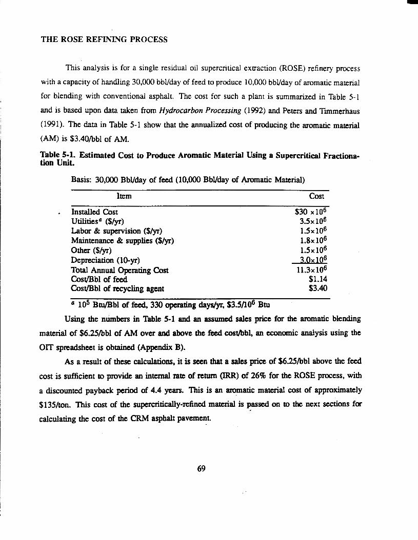
THE ROSE REFINING PROCESS
This analysis is for a single residual oil supercritical extraction (ROSE) refinery process
with a capacity of handling 30,000 bbVday of feed to produce 10,000 bbVday of aromatic material
for blending with conventional asphalt. The cost for such a plant is summarized in Table 5-1
and is based upon data taken from Hydrocarbon Processing (1992) and Peters and Timmerhaus
(1991). The data in Table 5-1 show that the annualized cost of producing the aromatic material
( A M ) is $3.40/bbl of AM.
i
Table 5-1. Estimated Cost to Produce Aromatic Material Using a Supercritical Fractiona- tion Unit.
Basis: 30,000 BbVday of feed (10,000 BbYday of Aromatic Material)
Item cost
. Installed Cost $30 x los
Labor & supervision ($/yr) 1 . 5 ~ 1 0 ~ Maintenance & supplies ($/yr) 1.8x 10⁶ Other ($&) 1 . 5 ~ lo6 Depreciation (10-yr) 3 . 0 ~ lo6 Total Annual Operating Cost 11.3~ lo6 Cost/Bbl of feed $1.14 Cost/Bbl of recycling agent $3.40
utilitiesa ($/yr) 3.5x 10⁶
lo5 Btu/Bbl of feed, 330 operating days/yr, $3.5/106 Btu Using the nkbers in Table 5-1 and an assumed sales price for the aromatic blending
material of $6.25/bbl of AM over and above the feed cost/bbl, an economic analysis using the
OIT spreadsheet is obtained (Appendix B).
As a result of these calculations, it is sten that a sales price of $625/bbl above the feed cost is sufficient to provide an internal rate of return (IRR) of 26% for the ROSE process, with
a discounted payback period of 4.4 years. This is an aromatic material cost of approximately $135/ton. This cost of the supcrcriticdy-refined material is passed on to the next sections for
calculating the cost of the CRM asphalt pavement. . .
69
CRUMB RUBBER MODIFIED ASPHALT PAVEMENT
This section compares the relative cost and benefit of a CRM asphalt pavement compared
to a conventional asphalt binder pavement. It is assumed that a new conventional overlay is
placed which is 4 inches thick, 30 feet wide (2 lanes), contains 5 wt% binder and 95 wt%
aggregate and has a density approximately twice that of water. With these assumptions, there
are 3,270 tons of pavement per mile:
(30 ft)(O.333 ft)(5280 ft) I (2)(62) lbm I ton of mix 3,270 tons of pavement mi I ft3 I 2000 lbm
- - mi
At 5% binder in the mix, this is 164 tons of asphalt binderhnile. Assuming that the CRMA
pavement contains approximately the same weight of pavement, per mile, then thcre would be
196 tons of CRMA binder/mile.
Capital Cost
The in-place cost of a conventional pavement is approximately $30/ton of pavement (0.95
t of aggregate at $5/t of aggregate, 0.05 t of binder at $lOq/t of binder, and $20/t of mix far
placement) which is approximately $98,1o/mile of pavement.
The in-place cost of a CRMA pavement, assuming the same costs except $1033 of CRMA binder (90% asphalt at $lOO/ton and 109b aromatic material at $135/ton) plus a proccssing
cost of $25/ton of binder for blending and curing, plus 6% binder instead of 5% gives a CRMA
pavement cost of approximately $12,2Wt of pavement man than the conventional pavement
or $110,300/mile of pavement. Of this increase, $8,400 is due to the cost of the rubber and
blending and curing process, $3,100 is due to the hgcr binder content (6% versus 5%), and
$690/t is required for the superior asphalt
Maintenance For both the conventional and CRMA pavement, a baseline maintenance cost was a p
proximated as one-fourth of the original capital cost of the conventional pavement (including
construction) distributed over the life of the pavement. For the conventional pavement (having an
average service life of 12 years), this is $2,WO/mile/year. For the CRMA pavement, assuming
70

a service life of 15 years for example, this is $1,635/mile/year, assuming that maintenance
procedures will be less frequent (occuring over 15 years) but technically no different than for
the conventional pavement. This level of maintenance cost for the conventional binder is sup-
ported by the actual amount, approximately $l,OOO/lane-mile/year (for conventional pavement),
budgeted for pavement maintenance by Texas DOT.
Several CRMA pavement performance levels were considered in the analysis. Each level
represented a different pavement life (15, 18, and 21 years) and was compared to an average life
of 12 years for a conventional pavement. To compare the two pavements at each performance
level over the same time period, the cost to replace the conventional pavement was prorated
over its expected life (12 years), multiplied by the additional number of years needed to meet
the projected life of the CRMA pavement, and then this total additional expense was distributed
over the entire performance period as additional maintenance cost. For example, with the cost of
the qonventional pavement at $98,1OO/milc, the added “maintenance” cost to bring the 12 year
conventional pavement to 15 years would be
and this is added to the usual baseline maintenance cost in the pncecding paragraph to obtain
the total. No such adjustment is mpid for the CRMA pavement since its assumed life is 15
Y”
Energy Use The energy use entmd for each pavement is the amount of binder used, converted to
energy equivalents. For the conventional material, this is
163.5 tons of asphalt 2000 lbm 20,000 Btu 1 Btu lbm 12 yr mile mi yr ton
= 545 x 106
For the CRMA binder, this amount is proportionately less because of the extended lifetime of
the pavement, but increased by the higher binder content of the pavement. Accordingly, for the
CRMA binder the p r a t e d energy use is
196 tons of asphalt I 2000 lbm 20,000 Btu 1 I = 523 x lo6 BtU
mile ton lbm 15 yr mi yr
71

Waste
The amount of waste for the conventional pavement is simply 3,270 tons/mile over 12
years or 273 tons/mi/yr. For the CRMA pavement, this amount is reduced proportionately due
to the extended lifetime of the pavement.
Table 5-2 summarizes the economic results obtained for three hypothetical lifetimes of
the CRMA pavement: 15 years, 18 years, and 21 years.
Table 5-2. CRMA Pavement versus Conventional Asphalt Pavement Comparison
CRMA Payback Pvmnt cap Cost Maint Cost Energy Use WaSte IRFt Period Life ($ 1o3lmi) ($/mi/yr> (lo6 ~tu/mi/yr) (tons/mi/yr) (8) ( ~ r )
(years) Conv CRMA Conv CFWA Conv CRMA Conv CRMA
15 98 110 3,678 1,635 545 523 273 218 14.9 9.3 18 98 110 4,770 1,362 545 ,436 273 182 29.0 4.4 24 98 110 6,130 1,168 545 374 273 137 38.0 3.2
72

REFERENCES
AASHTO TP3, "Standard Test Method For Determining the Fracture Properties of Asphalt Binder in Direct Tension (DT)," AASHTO Provisional Srandurd, Edition 1 A, 1-13 (September 1993).
Allison, K., "Those Amazing Rubber Roads," Rubber World, 47-52 and 91- 106, respectively, (March, April 1967).
Anderson, D.A., D.W. Christensen, R. Dongre, M.G. Sharma, J. Runt, and P. Jordhal, Asphalf Behavior at t o w Service Temperatures. Report FHWA-RD-88-078, FHWA, U.S. Department of Transportation (1990).
Andrade, E.N. da C., "The Viscosity of Liquids," Nantre, 125, No. 3148, 309-310 (1930).
ASTM D113, "Standard Test Method for Ductility of Bituminous Materials," Annual Book of ASTMStandardr, Vol. 04.03, 23-25 (1994).
Bahia, H.U., D.A. Anderson, and D.W. Christensen, "The Bending Beam Rheometer; a Simple Device for Measuring Low-Temperature Rheology of Asphalt Binders," Proc. Assoc. Asphalt Paving Technol., 61, 1 17- 153 (1992).
Blow, C.M. and C. Hepburn, Rubber Technology and Manufacture, Butterworth Scientific, 2nd ed., Boston (1982).
Blumenthal, M., "Using Scrap Tire Rubber in Asphalt," BioQcZe, 32(10), 85-86 (1991).
Bullin, J. A., R.R. Davison, C.J. Glover, and T.C. Billiter, Optimization of Rubber Content in Asphalt Pavement, Federal Highway Administration Research Report FHWA-RD-94-001 (1994).
Corbett, L.W., "Composition of Asphalt Based on Generic Fractionation, Using Solvent Deasphaltening, Rution-Adsorption Chromatography, and Densimetric Characterization," Anal. Chem., 41, 576-579 (1969).
Davison, R.R., J.A. Bullin, C.J. Glover, J.R. Stegeman, H.B. Jemison, B.L. Burr, A.L.G. Kyle, and C.A. Cipione, Design and Manufatwe of Superior Asphalt Binders, Texas
73

Dept. of Trans. Research Report No. 1155 (1991).
Davison, R.R., J.A. Bullin, C.J. Glover, H.B. Jemison, C.K. Lau, K.M. Lunsford, and P.L. Bartnicki, Design and Use of Superior Asphalf Binders, Texas Dept. of Trans. Research Report No. 1249 (1992).
Davison, R.R., J.A. Bullin, C.J. Glover, J.M. Chaffin, G.D. Peterson, K.M. Lunsford, M.S. Lin, M. Liu, and M.A. Ferry, Venpcation of an Asphalt Aging Test and Development of Superior Recycling Agents and Asphalts, Texas Dept. of Trans. Report No. 1314 (1994).
kmpster, D., "America Finds New Uses for Scrap," European Rubber Jouml, 161(4), 22-26 (1979).
Dempster, D., "Rubber Could Give The Road 100 Year Old Road Surface," European Rubber Journal, 160(4), 47-48 (1978).
Estakhri, C.K., S. Rebala, D. Little, Laboratory Evaluafion of Crumb-Rubber Modijied (CUM) Binders and Mixtures, Texas Department of Tmsportation Report #1332-1, written by Texas Transportation Institute, Texas A&M (1993).
Ferry, J., Vicoelastic Properties of Polymers, John Wiley and Sons, 4th ed., New York, NY (1985).
Fmta, I., Elarromers and Rubber Compouding Materials, Elsevier, New York, N.Y., 302-315 (1989).
Gagle, D.W., H.L. Draper, and R.J. Bennett, "Asphalt Rubberizing Compositions," United States Patent 3,779,964 (1973).
Good, R.J. and C.J. van Os, "The Modern Theory of Contact Angles and the Hydrogen Bond Components of Surface Energies," in Modem Approcrchcs to Wettability, Ed. E.M. Schrader and G. Loeb, Plenum Press, New York, 1-27 (1992).
Heitzman, M., "Design and Construction of Asphalt Paving Materials with Crumb Rubber Modifier," Tramp. Res. Rec., 1339, 1-8 (1992).
Huff, B.J. and B.A. Vallerga, "Characteristics and Performance of Asphalt-Rubber Material Containing a Blend of Reclaim and Crumb Rubber," Tranrp. Res. Rec., 821, 29-36 (1979).
Hveem, F.N., E. Zube, and J. Skog, "Proposed New Tests and Specifications for Paving Grade Asphalts," Proc. Assoc. Asphalt Paving Technol., 32, 271-327 (1963).
74

Jemison, H.B., B.L. BUK, R.R. Davison, J.A. Bullin, and C.J. Glover, "Application and use of the ATR, FT-IR Method to Asphalt Aging Studies," Fuel Sci. Technol. Int., 10, 795- 808 (1992).
Labib, M.W., "Asphalt-Aggregate Interactions and Mechanisms for Water Stripping," Preprints of Papers, 37(3), 204th ACS National Meeting, Washington, D.C., American Chemical Society, Div. of Fuel Chemistry, 1472-1481 (1992).
Lalwani, S., A. Abushihada, and A. Halasa, "Reclaimed Rubber-Asphalt Blends Measurement of Rheological Properties to Assess Toughness, Resiliency, Consistency, and Temperature Sensitivity," Proc. Assoc. Asphalt Paving Technol., 51, 562-579 (1982).
Lau, C.K., K.M. Lunsford, C.J. Glover, R.R. Davison, and J.A. Bullin, "Reaction Rates and Hardening Susceptibilities as Determined from POV Aging of Asphalts," Tramp. Res. Rec., 1342, 50-57 (1992).
Lindp, R.N., J.P. Mahoney, and N.C. Jackson, "Effect,of Compaction on Asphalt Concrete Performance," Paper No. 880178 presented at the Transportation Research Board 68th Annual Meeting, Washington, D.C., January 22-26 (1989).
Liu, M., K.M. Lunsford, R.R. Davison, C.J. Glover, and J.A. Bullin, "The Kinetics of Carbonyl Formation in Asphalt," AI- J. , 42(4), 1069-1076 (1996).
McDonald, C.H., "Elastomeric Pavement Rcpair Composition for Pavement Failure and a Method of Making the Same," United States Paem 3,891,585 (1975).
McQuillen, J.L., H.B. Takallou, R.G. Hicks, and D. Esch, "Economic Analysis of Rubber- Modified Asphalt Mixes," J. Tramp. Eng., 114,259-277 (1980).
Nadkarni, V.M., A.V. Shenoy, and J. Mathew, "Themomechanical Behavior of Modified Apshalts,' Ind . Eng. Cbn. prod. Res. Dev., -24,478-484 (1985).
Ohta, K. and translated by E.A. Inglis, "Modified Asphalt for Asphalt Road Surfaces," Znt. Polymer Sei. Technol., loo), T/44-T/54 (1983).
Oliver, J.W.H., "Modification of Paving Asphalts by Digestion with Scrap Rubber, " Transp. Res. Rec., 821, 37-44 (1979).
Pearson, C.D., G.S. Huff, and S.G.-Gharfeh, "Technique for the Determination of Asphaltenes in Crude Oil Residues," Anal. Gem. , 58, 3266-3269 (1986).
Peters, M.S. and K.D. Timmerhaus, Plant Design and Economics for Chemical Engineers, 4th

edition, McGraw-Hill, Inc., New York, 210 (1991).
Roberts, F.L., P.S. Kandhal, E.R. Brown, R.L. Dunning, "Investigation and Evaluation of Ground Tire Rubber in Hot Mix Asphalt," In Florida Deparmzenr of Tramponation Report, written by National Center for Asphalt Technology, Auburn University (1989).
Roberts, F.L., P.S. Kandhal, E.R. Brown, D.Y. Lee, and T.W. Kennedy, Hor Mix Asphalf Materials, Mixture Design and Construction, NAPA Education Foundation, 1st ed., Lanham, Maryland, 68 and 382 (1991).
Sainton, A., 'Advantages of Asphalt-Rubber Binder for Porous Asphalt Concrete," Paper No. 890163 presented at the Transportation Research Board's 69th Annual Meeting, Washington, D.C., January 7-11 (1990).
Shuler, T.S., R.D. Pavlovich, and J.A. Epps, "Field Performance of Rubber-Modified Asphalt Paving Materials," Tramp. Res. Rec., 1034, 96-102 (1985).
Stroup-Gardiner, M., D.E. Newcomb, and B. Tanquist, "Asphalt-Rubber Interactions," Pncprint of paper presented at the Transportation Research Board 72nd Annual Meeting, Washington, D.C., January (1993).
Takallou, H.B., R.G. Hicks, and D.C. Esch, "Effect of Mix Ingredients on the Behavior of Rubber-Modified .Asphalt Mixtures," Tramp. Res. Rec., 1096, 68-80 (1986).
Takallou, H.B., and M.B. Takallou, "Recycling Tires in Rubber Asphalt Paving Yields Cost, Disposal Benefits," EZasromeritx, l23(7), 19-24 (1991).
Thenoux, G., C.A. Bell, and J.E. Wilson, "Evaluation of Asphalt Physical and Fractional properties and Their Interrelationship," Paper No. 870531 presented at the Transportation Research Board 67th Annual Meeting, Washington, D.C., January 11-14 (1988).
Wilhelmy, L., 'Ueber die Abhbgigkeit der Capiitiits-Constantanten des Alkohols van Substanz und Gestalt des benebtar festen Kiirpem," h n a h Der W s i k Und Chemie, 119, 177-217 (1 863).
76

ABBRE\’IATIONS
AASHTO
AC AM AR ASTM ATR BBR CA CRM CRMA DOE-OIT DOT DS ENV ES
GCI GPC GSI GTM HPLC u IRR MP P POV PTFE RA ROSE RPM RS S SA sc S H R P TG THF TK TxDOT wc
FTiR
American Association of State Highway
asphaltene content aromatic material asphalt rubber American Society for Testing and Materials attenuated total reflectance bending beam rheomater carbonyl area crumb rubber modifier crumb-rubber modified asphalt Department of Energy Ofice of Industrial Technologies Department of Transportation Diamond Shamrock environmental exposed surface Fourier transform infiared spectroscopy gyratory compactibility index gel permeation chromatography gyratory stability index gyratory test machine high performance liquid chromatography initial jump internal rate of return metering pump pressure or pressure gauge pressure oxygen vessel poly tetrafluoroethylene recycling agent residual oil supercritical extraction revolutions per minute Rouse separators superior asphalt supercritical Strategic Highways Research Program Tire Gator tetrahydrofirran tank Texas Department of Transportation water cooled condenser
and Transportation Officials
77

E
NOTATION
cross-sectional area effective gauge length elongation at failure Lifshitz-van der Waal's component of surface energy load at failure low frequency limiting viscosity

APPENDIX A
EXPERIMENTAL METHODS
SUPERCRITICAL FRACTIONATION
A brief description of the supercritical fractionation process, operating conditions, and
apparatus modifications follow. The following description is taken primarily from the TxDOT
Study 1249 @avison et al, 1992) reprt with appropriate modifications. The unit operates at a
constant pressure above the critical pressure of the solvent. The SC fractionation unit q a r a t e s
heavy petroleum products into up to four fractions according to solubility in SC solvents. ' The
temperatures of the separators determine the density of the solvent and, consequently, the solvent
powp in each vessel. Components of the feed precipitate when no longer soluble in the solvent.
The lightest, most-soluble materials are removed by decompression during solvent recovery.
Figures A-1 and A-2 illustrate schematically the SC unit. The solvent is pumped to the
operating pressure in Sl-S3 by "1. Several hours are required to bring the temperatures to the
desired steady-state values. The steady-state operating temperature in S4 determines the steady
state pressure for S4. Once steady-state conditions are achieved, MP2 is activated, introducing
feed material into the circulating solvent stream. The temperature in each separator determines
the solubility in the SC solvent. The insoluble material is transferred from the separator to its
.corresponding collector periodically to avoid potential plugging problems while the soluble
material travels to the next separator. Finally, the overhead mixture from S3 passes through the
control valve, where the pressure is reduced to significantly subcritical value. At these gaseous
conditions, none of the asphaltic material is soluble and complete separation of the solvent is
=hiwed. The solvent then passes overhead, is condensed in WCl and flows back into the solvent
reservoir. For this DOE effort, n-pentane is the solvent used for supercritical fractionation.
m e four aqhalts fractionated during the first year of this DOE effort were fractionated
in Go passes -ugh the unit. The lightest fraction from the first pass was fed through the unit
79

80

so Solvent Tank
C1 -C4 Collectors
"m- In-line Filter/mixer
6
Control Valve
S1 -S4 Separators
A1 Asphalt Tank
"- Valve
Tubing Wall Temperature Thermocouple
Pressure Contrdler
Heating Tape Heater
a DualPurpose Heater/Cooler
wc1
Thermocouple
Temperature Monitor and Controller
Pressure Gauge
Metering Pump
Water Cooled Condenser
Figure A-2. Legend for Supercritical Extraction Unit Diagram
81

a second time yielding eight fractions that may be analyzed. The lightest fraction from the second
pass is designated as fraction F1 and the heaviest fraction from the first pass is designated as
fraction F8 (fraction F5 is the feed material for the second pass through the unit).
PRESSURE OXYGEN VESSEL (POW
The original unit is described by Lau (1992) and Davison et al. (1992). In order to
improve on aging simulation capacity, four additional units were constructed and a central control
panel was installed as shown in Figure A-3. Later, to eliminate temperature gradient problems
with the initial design, the vessels were placed in glycol/water baths.
Figure A 4 shows a schematic of one of the POVs. The vessels are located behind a steel
wall in an explosion proof hood. Each vessel is contained in an aluminum barrel Nled to the
boaom of the top flange with a mixture of triethylene glycol and water. The vessel is monitored
and controlled from a panel outside the explosion proof hood. The control panel houses a
compound pressure gauge to monitor the pressure, a variable transformer to control the amount
of electrical power to the heating elements in the waterhiethylene glycol bath, a temperature
controller which controls the temperature of the bath, and a recorder to monitor the temperature
within the POV. A stirrer is employed in the bath to insure that the temperature distribution in
the bath is uniform. A vacuum pump is used to evacuate the vessels before charging with oxygen
or to remove oxygen depleted air once per day. ' I k e valves per vessel, as labeled in Figure A-1 , are used for venting to atmospheric prtssure, evacuating to low pressure to remove the gas inside
the vessel, and charging with oxygen. The oxygen feed valve isolates the POVs from 'the oxygen
cylinder when closed.
Asphalt samples are prepared in aluminum trays. The dimensions of the tray are 7.0 cm
(2.75 in) b y 3 5 cm (1.38 in). Typical fdm thicknesses of less that 1 mm (0.039 in) are used to
minimize potential diffusion problems at low pressure; however, diffusion studies may be
performed with thicker films. After prepaxing the asphalt samples, loading the sample rack, and
allowing the temperatwe in the POV to reach equilibrium, the operator places the rack inside the
POV and bolts the cover flange to the top. The Vent valves, oxygen feed valves, and vacuum
82

- OXYGEN
CYLINDER
Figure A-3. Pressure Oxygen Vessel Control Panel
Figure A 4 Pressure Oxygen Vessel and Control Panel
83

valves are closed. A vacuum pump evacuates the air in the vessel to a pressure of 0.03 atm
absolute. The vessels are slowly pressurized to the desired level by manipulating the oxygen
cylinder regulator and oxygen feed valves for pure oxygen aging, or by slowly opening the
atmospheric venting valve for aging with air (note 0.2 atm oxygen is equivalent to atmospheric
air aging). Once the desired oxygen pressure is reached, the cylinder, regulators, and feed valves
are closed.
During the experiment, samples are periodically removed. TO obtain samples, the pressure
in the vessel is decreased by slowly venting off the oxygen to the atmosphere until the pressure
gauge reads zero. The operator removes the top insulation, unbolts the cover flange, and collects
the samples. Samples to be aged further are loaded back into the vessel, and the process is
repeated. The aged samples ate saved for chemical and physical analysis.
CORBETI' ANALYSIS
A description of the traditional Corbett (1969) analysis can be found in the standard
method ASTM 04124. Corbett analysis separates the components of an asphalt according to
polarity. Some modifications of the Corbett procedure were implemented to reduce sample size
and increase efficiency as suggested by Thenoux et al. (1988). .
MIXING APPARATUS
TO produce the asphalt-nrbber binders, asphalts and rubbers were 'cured' or mixed at high
tern- (> 177T (350°F)). Curing, for the pwpose of this pap, is defined as an increase
in viscosity without oxidation, with oxidation being measured by the carbonyl peak area of the
infiared spectrum. The curing PKKZSS, as carried out in this laboratory, involved mixing at high
temperatures with a 5.1 cm (2") diameter blade driven at variable speeds, 500-1550 rpm by a
variable speed motor. The blends were cured in either 1 quart or 1 gallon paint can, depending
on sample size, under a nitrogen blanket to prevent the binder from oxidizing.
84

BENDING BEAM RHEOMETER
Low-temperature properties of the asphalt-rubber binder, were evaluated using a bending
beam rheometer (BBR). Anderson et al. (1990) concluded that the BBR is the best instrument for
measuring low-temperature properties of binders. Furthermore, both S(t) and the m-value, the
properties obtained by utilizing the BBR, have been correlated with the low-temperature thermal
cracking of binders (Bahia et al. 1992). All bending beam results were obtained at a beam testing
temperature of -15°C (5°F). The beam specimens were produced and the bending beam rheometer
was utilized as specified in AASHTO Designation TP 1.
DYNAMIC SHEAR RHEOMETER
The intermediabtempemture rheological properties were tested with a Carri-Med CSL-500
dynamic shear rheometer configured in the parallel plate geometry. This instrument may be
operated in either a constant stress-mode (its natural mode) or a constant-strain mode over a
temperature range from 0°C (32°F) to 90°C (194°F). This instrument was operated in the constant-
stress oscillation mode for analysis of neat asphalt samples but the constant-strain mode was
necessary for analyses of asphalt-rubber samples.
The behavior of asphalt samples is non-Newtonian at intermediate oscillatory frequencies.
However, by utilizing the constant-stress mode, a limiting complex viscosity, qb, can usually be
obtained at low frequencies. For highly aged samples the low frequencies are obtained by
utilizing temperatures greater than the reference temperature and the time-temperature
superposition principle (Ferry 1985). For asphalt-rubber samples, however, at low frequencies,
a limiting complex viscosity can not be obtained. To complicate matters further, the strains
induced in the asphalt-rubber binders at low frequencies are quite large and may cause partial
destruction of the bonds formed between the asphalt and rubber during the curing process.
merefore, it is neceSSary to operate'the rheometer in the constant-strain mode for asphalt-rubber
samples. T~ analyze the asphalt-mbber samples in this study it was necessary to determine the strain
85

level which corresponds to the linear viscoelastic region. Theorectically, the linear viscoelastic
region exists in the strain level range from 0% to some maximum percent strain level. However,
a rheometer cannot accurately measure linear behavior at and slightly above the 0% strain level,
thus narrowing the range of the linear viscoselastic region. In reality the measureable linear
viscoelastic region exists from a stain level range of slightly above 0%, a minimum strain level,
to a maximum percent strain level. This range was determined by specifying several different
strains and observing the strain response wave. Linear viscoelastic behavior is encountered when
the strain response to sinusoidal stress input is also sinusoidal. The strain level for measurement
was chosen to be the minimum strain level at which measureable linear viscoelastic behavior
occurred. This minimum strain level was found to be highly sample dependent and ranged from
approximately 0.5 % to 200%, depending upon the temperature.
An additional complication to the measurement of,asphalt-rubber properties is the presence
oithe rubber particles. As a result, it was necessary to determine the gap width for the parallel
plate geometry. This gap width was found to be strictly a function of the rubber particle size and
rubber content. The gap width for a given rubber size and content was determined by measuring
the rheological properties of a given asphalt-rubber at multiple gap settings. To insure the
elimination of the ‘gap effect’, the gap width was chosen such that the rheological properties taken
at as wide or wider gap widths, were independent of the gap width.
BROOKFIEID ROTATIONAL VISCOMETER
A Bmkfidd rotational viscometer Model RVF 7 was used to obtain the high-temperature
(> 121°C) (250°F)) viscosities of the asphalt-rubber binders. Torque is applied to spindle placed
in the binder sample which is contained in a thermostatically controlled beaker. The relative
&stance to rotation is measured for a given rotational speed. The relative resistance, the spindle
size, an the rotational speed are then used to calculate the viscosity, q.
86

GEL PERMEATION CHROMATOGRAPHY (GPC)
GPC analyses were performed using a Waters 712 sample processor and a Waters 600E
multisolvent delivery system. Helium-sparged HPLC grade tetrahydrofuran (THF) at a flow rate
Of 1 mL/min was Used as the Carrier Solvent to efficiently separate the asphalt-mbber binders.
Three columns with pore sizes of lOOOA, IWA, and 50A were connected in series. m e 1oooA
and 100A columns are 30.5 cm (1 foot) in length and are packed with ultrastyragel particles. m e
50A column is 61.0 cm (2 feet) in length and is packed with PLgel particles. A. Waters 410
IXYerential Refractometer and a Visctoek H502 Viscometer was used to monitor sample elution.
The column and detector temperatures were controlled at 40°C (104°F). Samples were prepared
by dissolving 0.20 to 0.25 grams, depending upon the rubber content, in 10 mL of and
filtering through a FTFE syringe filter with a membrane pore size of 0.45 pm (0.45 micron).
Thk, sample prepaxation removes al l rubber particles greater than 0.45 microns, since asphalt is
soluble in THF and rubber is not.
FOURIER TRANSFORM INFRARED SPECTROSCOPY (FlTR)
A Mattson Galaxy series 5020 Spectrometer at 4 cm" resolution and 64 scans is used to
measure the infrared absorbance spectra of asphalt samples. In particular, the Attenuated Total Reflectance, ATR, me thd with a Zinc Selenide prism is used Qemison et al., 1992). To quantify
the changes in the spectra, the carbonyl content is defined as the integrated absorbance from 1820
to 1650 cm" with respect to the baseline at the absorbance of 1820 cm". This area is called the
CMonyZArea or ci. The range of wave numbers includes the following carbonyl compounds:
esters, ketones, aldehydes, and carboxylic acids. The primary absorbance peak for the oxidized
asphalt is located at 1700 cm" and cOrreSpOnds to ketone formation. The carbonyl area has been
shown to be a good measure of oxidation (Liu et d. 1995).
At low aging pressures of 2 and 0.2 atm oxygen and for thick (E lmm) films, oxygen
diffusion may be significant. To partially eliminate this diffusion problem, only the exposed
surface, a, ofthe film is analyzed for kinetic data. For analysis, a quarter of the material in the
87

aluminum tray is removed and the ES placed on the prism face. For samples that have been aged
in thinner films, diffusion is probably not significant, so i t is possible to measure the spectra of
a stirred sample. To insure good contact at the sample/prism interface, the sample is compressed.
Heating of the sample is avoided, if possible.
For measuring the spectrum of asphaltenes, the material is dissolved in THF and the
solution deposited on the ATR prism drop by drop allowing the THF to evaporate. When the film
on the prism is sufficiently thick it is further dried with a heat gun.
MICRODUCTILITY MEASUREMENTS
A detailed description of the microductility measurements can be found in Chapter 2.

APPENDIX B
S'READSEETS
89


Economic Analysis for a ROSE Supercritical Unit for Producing
Aromatic Material for CRMA
90


B
91

1 1 l 1 1 1 1 1 I I
i
0 0
0 0
9
s
92


d I
0 0 0- s 0,
8
94

g w r - r r w w r o r r r t 2 E q 0 0 0 0 0 0
= o o o o o o o o
1 1 0 1 ,

96

L
I
I
97

I I
:I l ' r r r r r r r r r r r 0 0 0 0 0 0 0 0 0 0 0 0 0 0 0 . 0 0 0 c = 0
98

8 8 1 8 8 1 8 ,
' $8 ' ' ' P f
I 0 8 0
I W
99

d
r.
! * I: - '*
la
ip c 0
2
* * * * * * * I !' -
I

Economic Comparison of a Conventional Asphalt, 12-Year Pavement
with a CRMA, 15-Year Pavement
101


t a f
a :: c
102


1 l 1 1 1 1 l 1 I ,
103

I 1 z x

105

I s 0 0 - 0 6

I
3
107

P
4
i
J i i !
i
108

n P
P
109

1
a *
a : a 5 - ob
110

8 8 n
t t
- c)
8
.. . 0 -
' 4
I


Economic Comparison of a Conventional Asphalt, 12-Year Pavement
with a CRMA, 18-Year Pavement
112


L
113

H
114

8 8 8 8 1 1
*****a
I
w
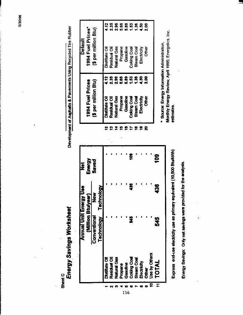
116
t *- b

UY 8
C 0 b s F U ’LI a! u) g
r 0
(I)
o z t f i z z r g = o o o o o o o o
~ 0 0 0 0 0 0 $6
n
1 1 1
1 1 1
1 1 1 1
1 1 1 1
0 0 - 0 )
OOCOk
3 B
I
I
5
f e
E
F
I W

118

\
-
1
119

120

, , 1 I 1 1 * 1
m q
a P a 3 - w
121

i:

Economic Comparison of a Conventional Asphalt, 12-Year Pavement
with a CRMA, 21-Year Pavement
123


8 k i?
124


P a
125

r
.I).*.* a
" s 0
.*.I) a
126

s d
127

H

129

P
j
!!?
\
-
\
130

I
131
8 8 8 8 8 8 8 1
8 8 8 8 1 8 8 8
132

+ a
t s
.. I: I. - '. I . l I . * * *
ii* !*
b