Embed Size (px)
Citation preview

.-1
. . ..,
(
•
NATIONAL ADVISORY COMMITTEE FOR AERONAUTICS
TECHNICAL NOTE
No. 1134
DEVELOPMENT OF A PROTECTED AIR SCOOP FOR THE
REDUCTION OF INDUCTION -SYSTEM ICING
By Uwe von Glahn and Clark E. Renner
Aircraft Engine Research Laboratory Cleveland, Ohio
Washington September 1946
co
https://ntrs.nasa.gov/search.jsp?R=19930081783 2018-02-13T00:21:48+00:00Z

/
r
NATIONAL ADVISORY COf.1MITTEE FOR AERONAUrICS
'l'ECHHICAL HOTE NO . ll34
DKVELOP~I~ OF A PROTECTED AIR SCOOP FOR THE
REDUCTIOn OF Il'IDUCTIor~-SYSTU1 ICING
By Uvre von Glahn and Clark E . Renner
SUMBARY
Aerodynamic, rain , and icing tests ,Tere conducted in the NACA icine; research tun"Qel on tbe standa.rd carb1..U'etor air scoo;;> of a l arge twin- engine car::;o air:;?L2ne an.d on several under-covTli.Dg scoops designed in an effort to elim~l~~te tbe chnracteristic ram- pressure loss accoP.Jpan.~TiDG impact lCing of the st'lndard scoop [.nd the carburetor screen . Tn't ancl static- ::?ressure-distribution surveys were mede on the lips of the scoo:;?s and total-pressUl'e ancl static-:;:>ressure readings Here taken at the carbUl"etor top deck to determine rampressure recovery and velocity d:!.stribu.tions . Rates of "Tater ingestion were determlned at tbree simulated fligbt and rain conditions . Icine tests of t~le various scooDs were made to determine the amount of duct and carburetor- sc~een icir~ .
T~le aerodynamic surveys in::llc.s.te that an lli'1der- covTling scoop of the tT}e investi~ated in these tests cen achieve ram- ~ressure
recovery comparabLe vii tb tbat of tbe standard scoop . The results of the rain- ingestion tests indicate tlw.t the under- covTling-type scoo:;? ingests less tban 5 percent of the free water ill the air ente:i.~ine; the induction system as com!=-ared vTi tb tbe standard scoop . The icing of the carburetor screen vTith tl-:e under-cowline scoop was negligible-j wheree.s wi tb tbe standard scoop it uas excessive .
IN'l'RODUCTIOH
A lare e t,·ri·:1- e:1gi::le carGo air::;>la:le was extensive ly used by tbe Indl<:l.- Chlna Divisio:1) Cbina-3urma- Inclia Air Tr'3.nsport CommanC'., to transport ,val' r:1ateriel. Reports from :Dilots "'Tho bave flOi-TD th'3se airplc.nes over tbe India- Cbina route duri::1g the monsoon season attribute the loss of many ~irplanes to induction- cystem icir..g . Instances where ice on the heated-air door prevented the pilot f:>c'om usj.l1G beated air bave been rel')orted . Tbe cOrlstant USE) of alcohol or l1eatod air FrOyed not to oe i'ea sible for tl1ese conditior:s. I"rt~rmittent nse of l1eated air fo:..' de - iclI'1-B involves tIle l1azard of :pl'olli-iJitive loss in altitude resulting from decrec.sed engine IlOi'Ter .
P'ACA TN No . 1134
Spin,ler fuel in;jection at tbe entra':lCe tc tbe supercbarger, vrbic11 if; s°(ianc1arcl 0 .:1 tIle engine of tbis car30 airpla~le , effectively reduces fuel- evaporation icing in the carburetor and the supercbarger inlet e 1'0 0>., , as stowr. in a Pratt & v!hitney A:'rcraft repo:ct and as demonstratecl. i'''l unrublisl:ed NACA laoorator~- data . Tbis ind.uction- system icing probl em is therefore limited to imp~ct icing of tbe scoop , duct , screen, and ce r :.m.retor-air meterinG parts and to tbrottling icing (I.ue to adiabatic e::pa~-_sio.f!. in tbe carbu::etor .
Elimination. of free weter from the i nduction system is an effective met:l0d of reducing tbe :icing rJ.8.zard, Darticularly wben t~.ere is no tendency tmm.rd fuel-evapore.tton coo:'ing and wbe.n ')arts belm·, tbe carouretor are tcIaintained at temperatUl~es aboye :reezing. A scoo:;;- entr ance dosign for preventiTlG tbe entry of rain by inertia se,aration -was proposed by Hillson H. Hunter in a pa:-,:,er entitled "Notes on Aircrqft Icing" given at tbe Hatlonal Aero.naut ic meeting of tbe Sodety of AutomJtive EnGineers at NelT York in March 1942 anet oy Kimball ( reference 1) . It was tl10ugbt that tbis de85.[,.n conld be used 1.,::' th lHtle or no additional aerodynamic losses . T:j.e case of a carGo a.L:;.~:~)lane o::,erating at its service ceiling thrOUGh serious i cing ITeatber warranted attem;.ts to adapt this :?ro:posed des lgn to tbe airplane :in ord.ol' to reduce tbe icing hazard ~n t" e induction system.
Aerod;ynaillic , r .'1in, a:'1.d ~ci::l& tes·vs 'irere conducted in the icing research tunt''1.Gl of tbe Ii:ACA Ole'leland la'boratory on the stanc,ard carburetor-air seoo::? a llo. se'l0ral ex]?eri.n:ental scoops , whicb viere intended to separate the rain from tbe air entel~ing tbe scoop . Tbe criteria seJ.ected for the des::'gu of the experimental scoo:9s are as follo,,1S :
1. The rate of free - "rater ingestion must be reduced to a minimum .
2 . Ram reco-rer] mus t be equal to or grenter than that of. tbe stacldard scoo::? uno.er cruising conditions above cri tj.cn l altitude .
3 . The scoo::? should be automatic in itE) operation, requirhlg no attention fro;-a the In lot •
Tbe u~!,er balf of an e:r1[;ine cow}J.P.g .Tas installed in tbe 6- by 9-foot test scction of tbe L::inC researcll tunnel. Two other center sect i onc "18re modif i ed to acco!lll1lodate t"ro 8X]1er:i.mental scoo:?s . A r ear falri:c1g -vTaS provid.ed back of tbe engine cowlil1g to reduce the blocl:i!1(s effect of tbe model and to provide an outlet for tbe
2

,
EACA TN ITo . 1134.
simulated e~:1gine cooli:ng air . The COl'!lil.:.g (fiGs . 1 and 2 ) was support ed by a cylh.dr ical steel shell , vhicb Has attached to a hinged base plat e 8 Inc~Je8 abo-;re tte tunnel floor . Fligbt angles of attack of 00 , 40
J
[1n(:;' SO mee,sured from tbe borizonto,l axis were simul3.ted by lower ing the Qo"mstreaD encl of tbe base plate . A ,woden darnmy engil1.e , representing t~le l.r'lper ba:'..f of tbe nose section of the engine emd eq'...~ipped ,litl1 c..iotrioutors anci ma[neto , '\Vas lilotmted on the oe,se plate in proper relatIon 'GO tne cmlling . T"TO orif:!_ce plates the.t could oe remotely ao_J~lsted to obtaj_-.1. t118 desired cooling- air flow through the engine compartnent I'Ten3 mountecl behind ~vl]e 'woel.en nose sectio:.1. . Finned electric strip :tea-cel's uere securod to tbe upstream or,;,rice plate to prevent icing of tl1e orifice orenic1os . The ori::::i.ce plates -yT6re calibrated against a st:.md::.t,rd circ'l,:lar orifice attacbed to the o::.;ening in the rear fairing of tbe moclel.
Tvo total- Ilressure rakes and a ztatic- pressure ri:lg (fig . 1) Iver e located in an adapter at tbe junctioLl of the inlet elbovT and a water se:::>arator that replacGcl the carbu:cetor . Ex:':' t duc'~s £'rom the se::>arator to botb sides of the cmvUng cor.rpleted. the test industion system . CbargG-a~r flovr tbrouGl; tl1e induction systeLJ ,vas regulated by l1ydraulically controlled flo.ps located in tbe ex-:i.t ducts . A 30- mesl' screen I-TaS placed at the fJeparator-·uir exits to i:.nYll'ove the air flmv in the instrWJented venturi sectiO!lS . S'catic- )reS"'Ul' e r;.r~s a:.1.d totalpress'J.re integrating rakes i:Cl the instr -..1.'!Jented section of tbe ex::' t ducts vTere used to measure tt,e cbarge- air mass flo"T . '\tIater entering t be scoop vIas separated from the air ty fOUl' la.~rers of parallel I'Tires mounted at an angle to the rtir st~_ eam in t!1G separator . The vater 'I'TaS tben continuo'_lsly draL:od ::'nto hlo :;raduetes . The separator Has calil)rated. by placing a vTater- S~)ray jet of Im01m capacity insj_de the duct and measuring the aDOU71t of vrater collected at several v2.1ue8 of ail~8peed and cl1arge- air flml . This calibration shovred tbe water se:-parator to be at least -;-5- 11ercent efficient . The duct air- stream teL1:,erature vIas me'1surect by lron- constantan thernocouples ins'~alled nt the carburetor top deck and instrL®ented sections of the exit Qucts .
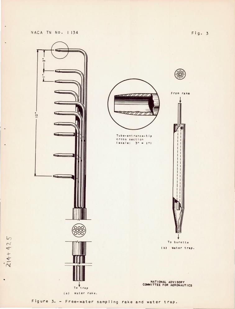
For eaCh :!:'~ in condition, a surve:r of tbe I,!ater concentration aJ::ead of the ecoo::? inlet \las made vri t~1 the 1';ater - sampliU[; rake shown. j.n fig1J.l'e 3 . The vater Gamples wel' e collected in indlvidua.l burettes for periods 7 to 20 mlnutes in duration .
DZSCRIFTIOi'J OF SCOOPS
Tl1e four scoops tested "Tere : (1) a star ... a..::rd ca:cburetor- air scoop; (2) an e:h.,])erimertal tmder-covl::'ng ssoop desig:aed to protect the duct f'roi;l tJle direct i.neestion of free 1-rater; (3) a I!lod:i.flcation
IJ.\.CA 'I'rJ Ho . 11:'\4
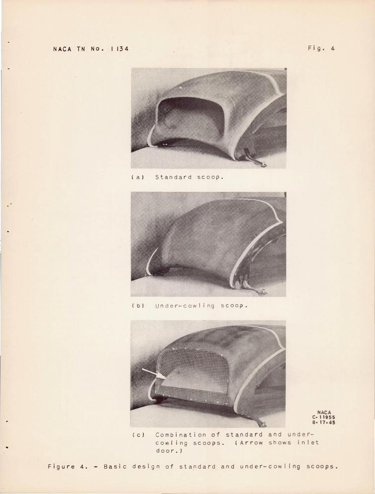
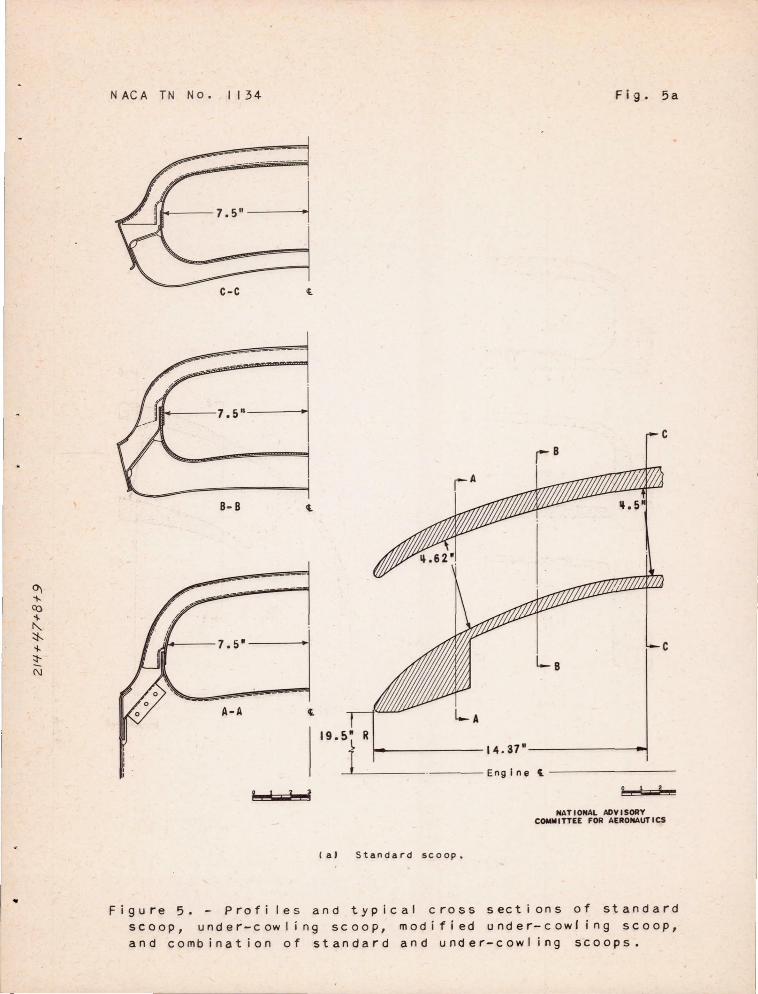
of Ue und.er-cowHI1£ SCOOT; and (4) a cOl"bi:oation of the standard a.:ld under- covlli .1g SCOO"l)S. The basi C de si,sns of tbo s .:oops c..re shovm in fiGure 4; t:1'3 SCOOl) profiles and tbe tyt?ical Cl'oS8- sect.i.ons are shown in figure 5 .
T~le duct of tho stanca:'d scoop has a cross-sectto.nal area of al']1'ox:im:ltely 70 s<l1..:are: i:nc~lE)s and extends bac~-:1vard 52 incn.es to a lOJc elbm-i leadir..g d.own to the cartl..TI'otor top dec:~ . A rotary-valvet;Y-':1e door fOl' aO.m i. tti"1f, beated air is fi tted r:'usb wi tb tbe floor of
the duct abeat of t1:e el'0o;o[. Several l:-inc.~ diametar boles are 4
::?r07ided abead of tbe rubber seal ~<t t~1e 1..l.})8tream ene"l. of tbe heatedair V3.::"ve to c.ra:!.n tbe 11ate:~ t!JD.t runs 'of'.ck on tl1e d'.let floor . For tl:ese tests tte interior of tbe c:.ucts, illCludi:1g Jelle si .... ::.e members of tbe beated-a:i.r valve, vre,:'e ss~l_'::d ,.,it:; S~Lee'G rubber cementecl .in rla e in ord8r that ,O[3,ter and. air 1elka3e '110uld not infl1A.ence the results . A vertical door, \·Tbi.:. .. ~b admits filtel'ed air and wbich. forms tbe rear vall of tbe c:.uc·t; e:Lbov1, ,res plso sealed :'or these tests . A remova'::lle tra:'ls:;?are:1.t llCtch was :?J.aced directly above the carburetor scree!1. to perni t obsary"i~1£:' a:._o. pboJuog:'a:;:J~1ing screen ':'ce for T'Jations . Only the forward ~.::".3'f i .. nclJes of tbe stanoiard-cov11ine center sectlon ',Tas altered j.n J:,re:1ar h"1£ the eX-yerirrental scoops for test .
As shown in fiGure 5, tl:e \.~ndGr- covT:in~" 8COO~ is desiGrlen. to :;rotect tb e duct inlet from 'cbe o.i:'ect in..geation of free vlater . I'Tater separation by the lJ'::·Ld.er-cCJvTl::.nrs scoo:? depenc1.s on the relatively grect '~nertia oZ t!le 1'Tat~r dro:iLets , '-Tticl"] causes t:he droplet8 to cO':lti.71ue in sub . .:;tar.tially s'~raig};t-liCle -')a,ths u1Jile tl;e cbarge ail' curves sharpl:- :';'pto tl1e scoo::-; . .4. t:.:ecretic.3.1 e.r.B,2.ys:l.s of the inertia-oe:;aration :~r .~nci]le as a:?~ · J.ied to the under-coi'Tling scoop 1S l)resented in the a2)pendix . Tl1e front lip of t~e 1..md<3r-COvlling scoop is curved c1Oimvffi.rd until t:,e leading edc;e co:lnc':'des wi tb t:'le former position of the leading ed3e of '~be lower li::;> on tbe standard scoop . TIle l'en~ li, Ls located as !1ieh and. as far forward as lJOS
s:cole to obtaJn the snarges'c turn \oTitbo~lt reClucine; tne inlet area .
Tbe ob~ect in t~1e design of' t··.le Lodified l.mder- covTling scoop vas to increase tbe r3.oj U8 of cur~!ature of tbe inlet :;?assage oy fllllnc Ll tl1e concave rear s'J.rface of t~}e front lip of tne origi!;al uncler-cowlin3 seoo::? Tbe rear lip vTaS cut b8,ck to r,-;cLntain an adequate inlet area . Because of t .. e r>..a.t1.U' e of tiw c0nstruction of t:18 b3.sic under-co'"Line; seoo:;?, it 11as imposs:!'ble durL"l5 tbe time available for tLese tests to altel~ tlle outer contour of tile fro·.lt lip as rer!:1itted by tbe interna'. cb:mges; tb~.s c1:aD£e l·rould be desirable, 110wever, to l'educe tbe I-TeigLt of the scoop 1nlet ar:d to i:nprove the exterm,l fairJng .
4
,
•
NACA Ti'l 1"0 . 1::.:::4
A scoop incor)0:~at1I1g the features of botb tJ:e standard and uErler·-co~Tli~l£ scoops (f ig . 5 ( e)) was also designed and tested, P_ sc:.:ee:Cl was )J.aced over the ram inlet of tlle standard scoop so that lll'ecs'.;.re differences cauRed by th e ici~ of tbis screen would tend to o~~)en a door l ~ inced a short ci.istance "back from the leading edGe of t~1e 10\1er li::? on tl-~ e cluct floor . Tbe door vTaS designed. to block automatically tLe entire ram Ol)enlng and form the outer vhlll of an in~_et elboi/T of at:. under -cOlvliC1fi -i.ntal~e similar to the bastc desiGn tAoted . .
SYHBOLS
The follovrlng symbols are used in the report :
Hua DveraGe total pres"'u.re at cerbnretor top deck, i'1.cbes of water
Hl total IJ:· essure of free air stream, il1.cl1es of water
L cross-sectional f:::>J.'e-and-o.ft ,·ricltb of carburetor top deck ,
P
Pl
C! l...-
t
IT
V d
Vda
Vl
li c
i n c:,es
clistance froD fOrl-mra waH at tOl? deck to total- pressureral.ce tu~)es , h1.c~1.es
local static pressure 0'.1. scoo:;? surface , incteB of water
test sectJon free - stream static pressure, incbes of water
pressure 11 / ~ 1 r 'n - Pl\l L -\ ql )-1
te~peratl~e ln tunnel test section, ~
indicated alrs~)eed, miles per bOUl~
local ii.l.clicated velocity of ai:' stream at top deck averaged for two ral~e8 for each station value of 7- , feet. :)er second
average ind ~. cated veloci t:; of all~ stream at top deck based on distrl-;:;utio:C".L of Vd , feet per second
indica~ed fr ee- stream velocity in tunnel , feet per second
cbarge- air flo·r, ::?ounds yer l-wur
rUCA TIT Eo . 11:;4
~I coo1 i:1g -a ::.r floYl , 1)ouncls l)er seCOl1C .. e
c, Fl ng J.e of attc.clc from 110r~.zon.ta~. axIs , degrees
Db8Cl:nFTI01~ OF TESTS
Studies w.:.th vTOO'. st.reame:;.~s i·rere 1D'1de to deter mine t he nature of tbe [~ir f~.o.r fror.:! a region :'l.pp:~oxi:na"'jely ~. feet upstream of the front of the mo(~el :in a ".-erJ.jical 1'1a:"1e ;)assing througb the center of the model. '';''l'f·c ocse:;."va·cio:tiS for the und.er- coi·~li11g scoops were made from a .,indm., i:"1 the top of tbe tunnel test sectio:"1 uoinc a m i::-r 01' mounted on the rI100.e1.
T1'Je test conditions fo::." aero(l~m~mi~ a:."1d s:i.mulated-rain tests 8.re listed in the fol::'owing taJle :
Fligbt condition
I Approximate aiTspeed
V (ml)l1 )
!An~le of Charge- air I Coolinc-I attac:: flow
T
I a:'r flow i (j, .. c vie I (deg) ( l b/n:r) (lb ! sGc)
High speGd I Cruisir::g I Steep cllnb
I (a) 20(' t --- 0-, -1 12 , 1)00 42
160 I 4 I 7,000 26
aOne- half of _16_C __ ._' __ ~ __ ..;..! __ 1_2....:,_0_0_0 __ -,-_ _ 4_2 __
these values i'le~"e 11.s<3c1 for the hal£-e112;ine mod.el .
In order to determine tl:e ae:tod.;TJJar.lic cl,aracteristics of tbe scoops , pressure d5stributions around t!Je scoop lips i.;ere obtained using preCSUl"e belts described in re2'ercnc3 2 and sl10vrn 1n figure 6 . Total- pressure BUT-reys made at the carburetor top deck vere photographically recorded. from a multi tv.be manometer .
Tbe free - i'later i":c estion characteristics of the 8COO~S i.;ere determined in simulated- rain tests wi tb nom1n~1 water concentrations of 0 , 3, 6 , and 9 cr3.DS per cuoic me'~er at the three basic fligbt cond.i tions . The "!Jod.ified und.er- covrl:'mg scoop was tested only under tbe cruising-fllg:,t coniitio::l .
The .,ater- dro'91et diameter Has determ::'nerl by measuring samples caught L"1 cas~or oj.l in still air ber:eatb the spray nozzles . Microscopic measurements of diameter .Tere converted to d.rop volULJe and the total volume 0-:: eact; size range vTaS rlottec1 agalnst droplet size .
6 • I
,
NACA 'l'N Ho . 1134
TlJ8 effect of t he relatively fe,,! large 02'OPS .las ::,redom2.na~l.t in locating tte peak of the curve, or "volUlJe maximum ," at 85- to 120-- micror_s diameter ~"'or spray conditions correspondIng to -vra-c er concentrations of 2 . 0 to 11. 5 gravos :,)er CUblC meter , respectively . A red1_wtion in drople-c s::'ze caused by the acceleration forces in the tunnel contl'action section has been observed but has not yet l)eeT! qua!ltitatively measured . The actual d:.~op2.et sizes probably "Iorere smal2.er than indicated by measurements in still air .
IcinG tests were made on tbe standard and under- covTling scoops for the same basic fl ight co ditions at angles of attack of 00 and SO and at test - section free-stream tem~)erature of 150 a::ld 250 F ,yitl1 an average "Tater cOEcentration of 2 to 4 grams per cubic meter . The mouified under- cowling SCOOT) was tested only at an angle of attack of 40 • Variation of ,rater content ,-rith temperature due to freezing of some of tiie l·rater ::'n the ai:.~ at 150 F may haye resulted in lower icLClB rates ~)Ut thie variation could. not be determined . Photogra;)hs of tbe scoops were ta):en every 2 minutes durinG eacb run, the daration of l1hieh varied from -;,0 ::'0 to 20 minutes; at the encl of eacb run , the carburetor screen and tl1e scoop entrance were photograpbecl .
TEST RZS1.1LTS
erodynam':'c Tests
Flow studies . - Surveys around the s -~:;andarc_ seoo:::-., made with a viool tui't , Eldicated flow separation from the inslc.e of the lm-rer
lip . Viool tuftf-J 11: inches long fasteEed on the inside of tbe under-2
cowling scoop -indicatec_ SeIJaration on tIle Q'l.de:- side of the front lip and -the sides of tl:e [;coo~ . 'fbe stlrface area on l.,rlj lCh se~aration occurred vlas decreased by Dod1fying the under-covTling scoop .
Stat:c- pressure distri~utions . - Pressure distributionc are presented i:1 terms of the preosnre coefficient S along tbe scoop surfaces and are sbO'.ID i on fieure 7 for tuo fli3ht conditions used in the investigation of the standa::.'(l scoop . The pressure distributlon over the li:?s of the standard scoo~ sows D. ~ig:l negative pressure on tl]e top surface of tl"Je upper lip wi tl1 a poeitive presS1.1re 0-_1 t~le lovTer surface; I-Tbereas t:'-le lovTer- li~ survey sbous a positive pressure on both surfaces . Tlje stabnation point 0:1 each lip Fas located near the leading edge or.. tile lower surface . For the assumed fligl1t conditions only sliGbt variations in pressure distribution occurred for changes ';"n angle of attack , charge- air
7
l'J:\.CA TN Ho . 1134
flovT , and cooling- air flo"T . An increase i n the charge-air flow from 7000 to 12,000 pcunds per hOl~ , while the an81e of a t tack, airspeed , and. p:rol,ortionaiie cooling- air f lmv wel~e maintaine d cons t ant , decreased all of the pressures on tbe upper and the lower l ips e xcept a t the stagnBtion points .
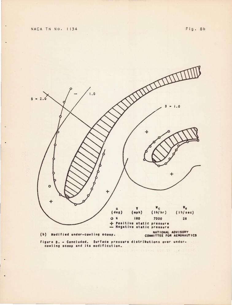
On tlJe u..l1.der-cowling scoop) positive pressure exi s ted on the outer surface of the front lip near tbe leadin[; edge and a l l along tbe inner surface (fig . 8(13.)) . Tbe exact distribution of pressures ar01.md tbe leadtns edge of tlle lips is lli"'"lcertain becal.se of t he
l:-incl1 spacing of t1,e pressure stations . The modified lmder- c01fllns 2 scoop was designed and t9sted j.n an effort to improve the pressure d5s·Gribut ion of the under- cmvline; scoop by moving the stagnation point near er the leading edge of the front lip . Favorable pr essure graclients existed alon{; the outer 81JTface of the 8C00:9 and. the stagnation points "TG1~e at the lead.ing edges of ·ooth li?s (fig . 8 (b) ).
Carburetor top- deck meaS~~0~ents. - T~ical velocity distribations' across the top deck are sSmm in figure 9 for the st8.i1.dard and under- cmrliI'..{3 scoops . U:ro.er the rJeveral test cO'.l.ci.i tions for any one scoop, the yelocity and tte total-pressure distriiJutions at t he top deck were similar . As ilJustrated in fi~ure 9 , the distr ibutions are more unifor:n for tne under- cO\·rling SC001) tban for the stanc.ard scoop, T)robably bec?l4~e :;:'low se1)aration OCCUl~s on tbe lower lip of tbe standard scoop ano. not on tbe lower lip of the under cQl'rltng scooll .
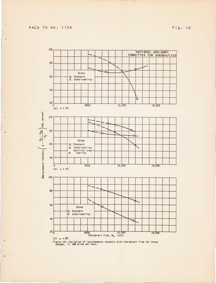
The percentage total or raB- presslTe recovery vms calculated as
(/ Rl - Rda ) 1 - 100, wbere Rda was obtained by integration of the
\ HI . total- pressure distributions shown in figure 10 . By ext~apolation,
tbe under·- co"rling scoop had greater ram- prese:uro r e covery at an angl e of attack of 00 and a cbarge-air flow of 7000 pouncls l)er bour and a considerably smaller reco',rery at 12 , 0'')0 !-lounds per bour tban the standard scoop for tbe sat:1e com1..i t1.ons . At an aIlble of attack of 40
tte ram-:9ressure recovery for tbe undor- oowl:i.ng scoop was slightly h ::,gher tban for t1:e stcmdard scoo") at charGo-air flOi-TS belmr 10,000 pounds 1jer hour but tbe 108S6S "rere higller for the underGOI-rl i !lg seoo::.:> at €:,reater air flm-1S . Rnm- preosure reeove:des f or t be modified under-co"Tling seoo:!? at tl1ese same condl tions are 31so shmm Hl figure 10(b) . The modified under- co"rllng seoo::? deraonstratecl b1gber recovery tban the otber 8COO::>8 at an angle of attacl~ of 40
for the condition used in tbese· tests . For an angle of attack of SO (fic, . 10( c) )] tbe ram- pres8ure recovery for the under- covrling scoop
8
NACA TN Ho . ll34
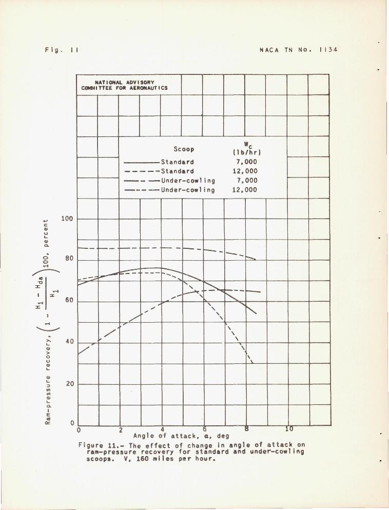
was considerably higher tban for the standard scoop . The recovery for t~le scoops generally decreased with an i ncrease in charge- air flo'ir . The effects of angle of attack on the relative performances of tbe standard and. under- cowltng scoops are compared in figure 11 at an airspeed of 160 miles J:ler hour for tIle two values of charge air flow . The ram- pressure recovery for both scoops at anGle s of attack of 4° and 8° are lower for charge- air flow of 12 , 000 than for 7000 pounds per bour. For the standard scoop at an angle of attack of 0° , this relation is reversed and for the under- cowling scoop the r am- I':;:-oessure rec07ery at 12 , 000 poena.s per bour is approximately one - half that at 7000 pounds per bour .
H H ' Tbe comparEltive ram- J:lressure recovery 1 - da \100 of
HI / the three s coops for tbe three basic fl iCbt condltions is presented i n the follow'ing table :
Scoop rAngl~ of lAp pr o x- ICharge- Icooling-1Ram-attack l;:;ate air flo,", air flol-T I pressure
a, airspeeCll f" vle . r ecovery (deg )
V c (lb / sec) I (pe rcent) (L'Jph) I (lb/br)
'- - -Standard 0 I 200 11 , 900 42 75 . 5
4 160 7,200 26 76 . 0 8 160 11) 800 40 I 35 . 3 -
Under- 0 180 12,000 42 48 . 3 cowling 4 160 9,000 26 77 · 2
8 H~OO 37 63 . 5 Modifieci 4 160 8 , 000 25 91.4
under-. I . cOl-Tling
From aerodynfu~ic considerations for high- speed level flight, the standard scoop is more satisfactory tban the u..."1der- cmrling scoop . For steep climb at sea level or cruise at ceiling conditions , the under- cowling scoop has greater r ara- press ure recovery than the standard scoop . Furthermore, the r am- pressure recovery for tl1e modified under- cOl'TlinC scoop at cruising condit ions is higher tha..YJ. for oi tber of the other scoops . Tl"e aerodYl1.amic perfornance of the modified under- cowling scoop based on the r esult s obtained at an angle of attack of 40 will probably compar e f avor ably with tbc standard scoop for bigb- speed level fligbt and be still be t ter for climb concli tions .
I'JACA TN No . 1134
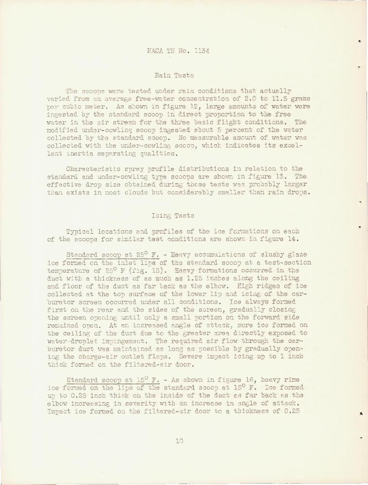
Rain Tests
'r_~e 8COO])8 were teeted under l~e.in conditions that actually varied from J.n ave:r'af,G free·-vater concentration of 2 . 0 to 11.5 gr ams :ger CUJlC ille ·Ger . As S:10wn In fi&,ure 12 , large amounts of water wer e ing,ested by the "'tandard scoop :;'n direct proportion to tbe free .rater in the air strea::J for the th:;.'ee basic flight conditions . The modified under- cOivlin:?; scoop ingested about 5 percent of tbe wa.ter collected by tha standard SGoop . No measurable amount of water '..ras collected vTi th the under-cm·Tli.i.1[s scco"") , .,bicr. indicates Hs exce 1-lent l.n.ertia sepi".rating qualities .
Characteristic spray profile distributions in relation to the stand.arcl and under- cowling type scocps are sbmm in figure 13 . Tbe effective drop size obtained c-trr'::'ns these tests W'3.S pro-J3bly larger tl1an exists in 'oost clouds but considerably smaller t:lan rain dro:;!s .
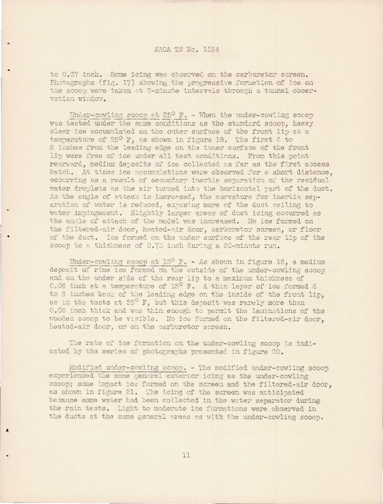
IcinG Testa
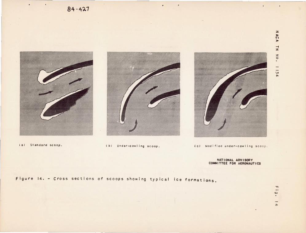
Typical locations C'.'J.d profiles of tho ice for!CJat::'ons on ee.ch of the scoops for similar test r,onditions are ShOWE in fi6Ul'e 14 .
Ste.ndard scoop at 250 F . - Heov~r accUIDuiatlo.:J.s of slusby glaze ice formed on tbe inlet liT)8 of the stAE(.'i-ard scoo:;? at a test-section tem~")eratu:.~e of 250 F (:fJ.g . -15) . tl"3e.vy formations occurred in the duct witb a thickness of as muc~ as 1 . 25 jnctes along the ceil~ng and floor of the duct as far tack as tbe e lbm! . Eigl1 ridge3 of ice collected at the to, surface of tbe lm-ier lip ~. d icing of the car-I.)uretor screen occurrad u.n.(ler all condl tions . Ice al,v8Ys fo:c:ned flrst on tbe rear and the sides of tbe screen, gradually closinc the screen opening until only a small portion on the fOl~"ard slde reliJained o-pen . At an increased. engle of attack, more ice formed on tl1e ceiling of the duct due to the E,reater are'3. dlrectly ex-posed to water ·dro:91et j.m~")ingemeG.t . The re~uired air flow througb tbe carburetor duct vas mainta l ned as lonG as liOssi-ble by gr8.dually o:Jening the charge-air outlet flc11S . Severe im~)act i~ing up t o 1 inch thick fornad on the filtel~ed-air doc:!:" .
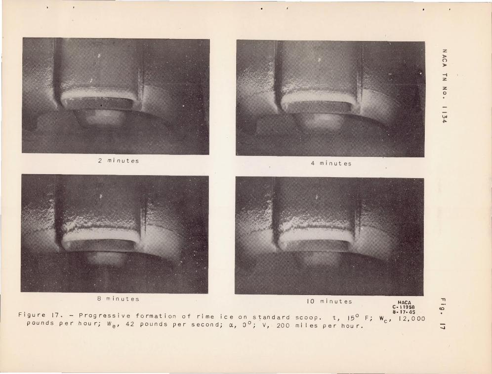
Standard scoo~ at 150 F . - A.s shOim in Ilgure 16 , beavy rime ice fo~ed on tbe lij!s of t:1e stand.t::rd s~oo:9 at 150 F . Ice fOT".G1ec1 ur to 0 . 25 inch th.ick on tbe inside of the duct 28 far back e.s tbe elbow increesing in severity Wl th an increase in "3.TIf,le of attacl: . Impact ice formed on tbe filtered- a ir door to a t11ickness of 0 . 25
10
---------------- -
N .. I\..CA TN No . 1134
to 0 . 37 inch . So:ne icing \·ras obse:;,'vec'.. on the carbureto:.' screen. PhotoGraphs (fig . 17 ) sl"lmiil1-l::, tbe j,JroGressi';e forl11et':on of ice on t~')e scoo:J vle:'::"e taken cIt 2 - mhmte interv'1:;"S throt'sh a tmmel obseryat~on \nllclo~! .
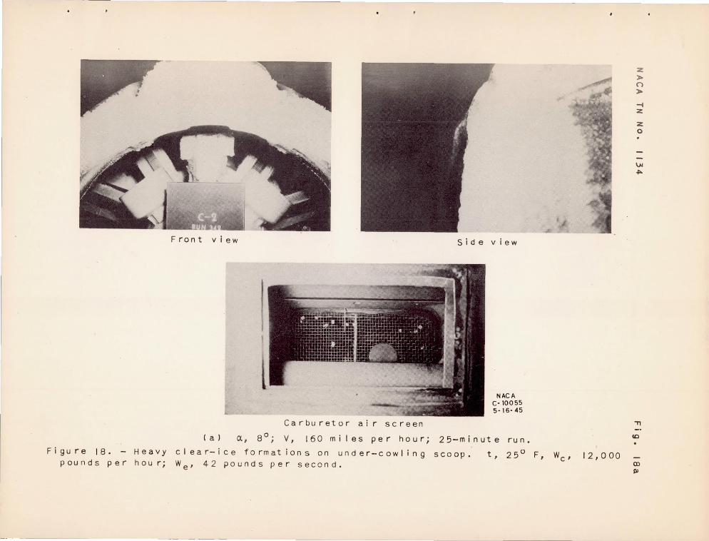
Un0.8:'-C01-rlins ecoo}! ct 250 F .. - Hhen tl:e nnder-cow:U·l1S scoo, vlB,S tested. underthe sL.:necoldHions as tbe stcndard SCOO!), heavy clear ::'ce BCCum '.latea on the outer surf':'tce of tbe Lont lip at a tem::!eratu:'e of 250 F, as sbown in figure 18. Tbe first f to 8 iDches from t~~.e leadine:s ed.ge on tl,a inner surface of tl:e fror~t li2,) 'fere free of' ice under all teat cond.~.t":'(m3 . From tbis point reFl.rYlard , medium de:;;os~ts 01 ice collected. ~.s far as the f).rat avces s hatch . At tirr;es ice P..ccuE1J.~ations "\ore:;.'e observed for e ShOl't distance, occm'r::'ng as a result of second.ar:" i'-lertie sep-3ra'clon 0:':' th.e residual Hater dro::;;lets as the ei:.~ tUl'ned ::.ntJ t~le hor::'zontel::,-:al't of the eluct . As the angle of ettac~\: is i;'lcropsec~, t:h.0 cUl'vature for ine:!.'·ti 1, separ'O'.t~on of vater is reduced, e:~:::-os~ng more of the duct sclliIlB to ulSter ir;:r;?Jngement . Sl:!.ghtly larger a:ceas of duct icing occurred as the anGle of attack of tho mo':e: H[.S inc:;.'e"tsed . ~o ice formed on the filtered-air door, hcatod- '-'ir door, carilt'.reto:;.' screen, or floor of the duct . Ice fOr::iJed on th8 uac.el' s<.u'f.?CO of the rear l::'p of the scoop to L~ thi c~~.ne ss of O. '(.5 LlCh clur:'.rlB a 2C·-minuto ru..lJ. .
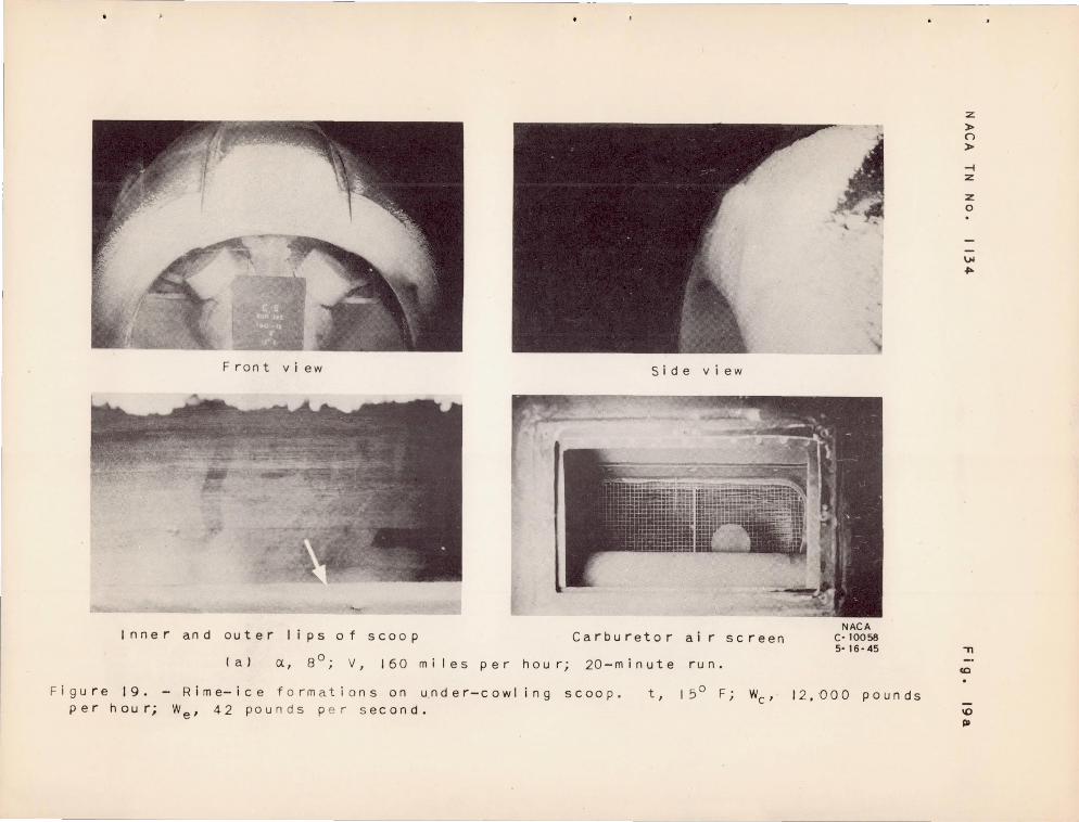
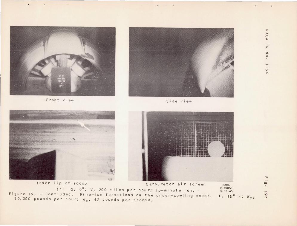
Under- cmfHr.g scoop at 150 F . - AS sho':-:TI ":'n :::igure 19 , a medi lJ..'1l
deposi t o~ rime ice forrno'ci. on-tlie outsi "I.e of tiLe under-,covTHng scoop encl. on tho under side of tho rear lin to a m2xirum th~.c!c.t!ese of 0.06 inch at a tem:;:Jorctu:.'e of lCO F.- A 1j~ll.n layer of ice tormed G to 8 inches beci.: of t~J.e leadinc; edee on tte inside of tl')e front lip, as i:l tho tests at 250 F, but tl1is d.e~. osi t "las rarely more than 0 . 06 inc:h. tl1.ic}c and YT'3.Z ttin enougl, to perm:;' t the lruain3.tions of tho Hoo(len scoop to be visible. No iCE! for-ned on the fi:i.terod- air door , heatGd-ail~ door, or on the carburetor screen .
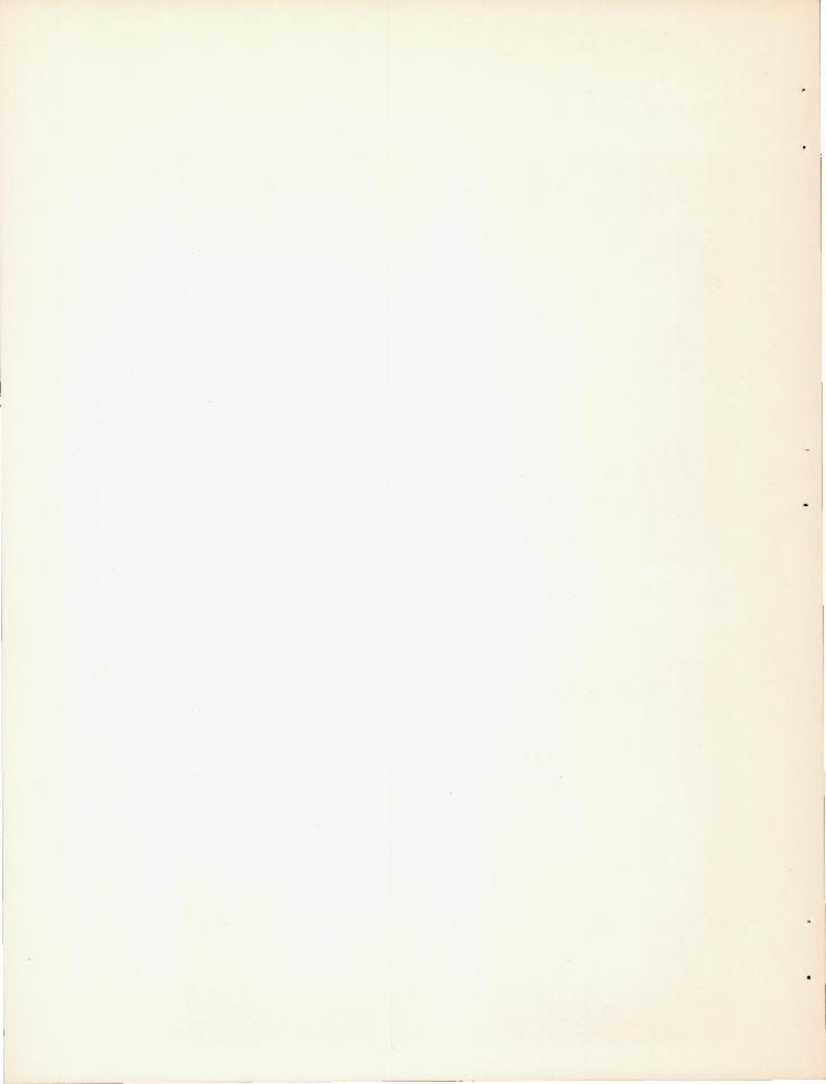
Tlie rate of ice fOrrJation on the under-co1-Tlit!g scoop is indi ceted by the ser~es of photoLraphs presentee<. in figure 20 .
Modified ulJ.de:c-cmvling SCOOy, - Tte mod.ified under- eovTliI1..g seoo::? experienced t:'-Je seXle sen,1ra::" exterlor icir..3 as the under-·cowllng scoop; SOLle ':'mpact icc formed on tbe sc:c-ee.:l. and the filtered-air door , as shmm in figure 21 . ':2:::e icing of the screen was antici!Jated be ... ause some wa'~er Lad been collected in the we.tel' sepa ... ator during the rain tests . Light to moderate ice forrJations were observed in the ducts at the same general :reas '}s ".:.t:h. t:1.e under- cowling s coop.
11
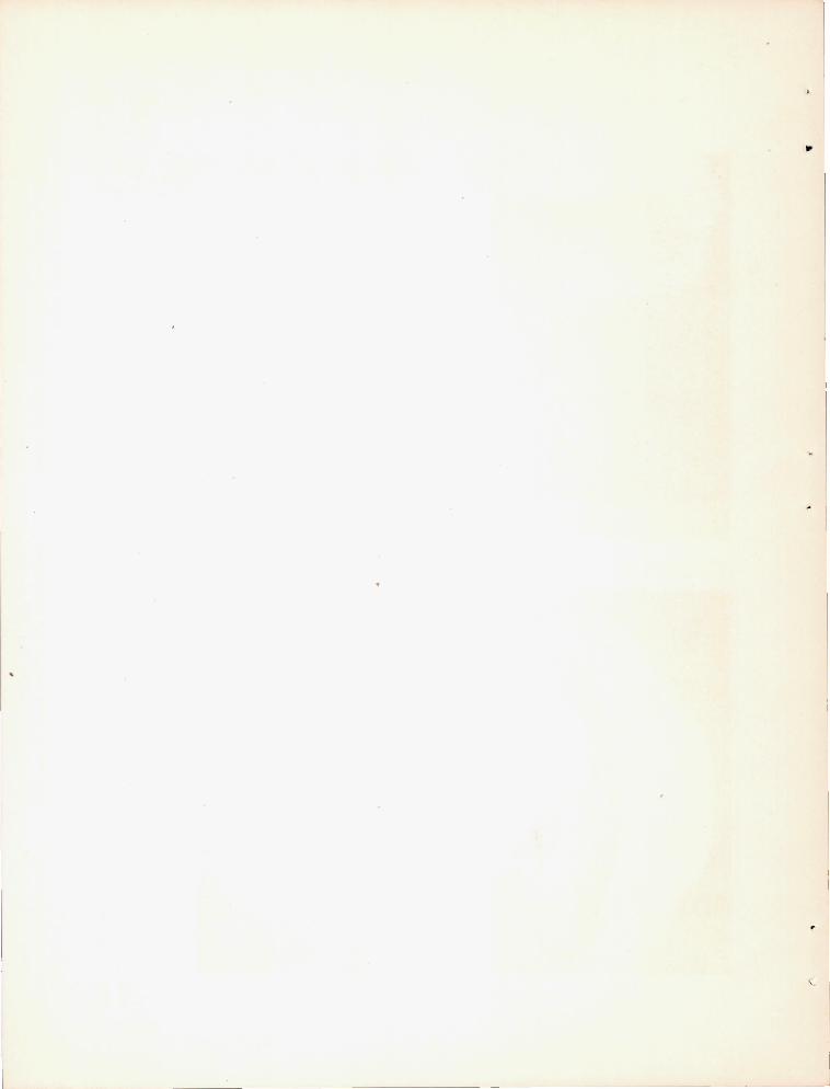
Comblned standard and under- cowling SCOOP . - Icing test s were co::!dl'.Gted on the comblnedatandard and und_e:c- cowl:i.ng scoop with a 4- Lles:il screen placed over the ram inlet . Because the inlet screen I'lUSt become :;:lur;ged v1::' th ice bef0l1e the door vTill open fully, this 8COOp cid not provide effective i.11ertia separ.3.tion until the screen was fully icee. . COEsequeEtly, this scoop under icing conditions permi tted a consid.era-ole e::nolmt of ice to for m on tbe car blJ.retor screen and hea-vy duct icing vTaS noted . Tbe amount or icing of the carburetor screen varied wi-sb tbe degree and rate of opening of the llnder- covlling door; hence , ",ith the iCi-.1g rate of the scoop- entrance Gcreen . A 16- mesh entrance scree:"l gave iml)rOved performance in icing conCii tions , as sbmm in figm'e 22 , but at the expense of increased ae r odynamic losses in nonic~ng conditions .
DEVIATIONS FROH TRUE FLIGh"T CONDITIONS
The simulated conditions in the icing research tunnel for tbe tests of the scoops differed from true flig:, t conditions because of the na ture of the setup 8.nd tbe tlli' ... ,'.'1el chnracteristics . The main deviations are :
1 . The tests 1-1ere conducted vithout benefit of eng:i.ne heat , llbi.cb in true fli3ht conditions may tend to decreo,se some of the carblITetor- duc t icing .
2 . The ram- pressure - recovery and vmter- ingestion measUl' ements obtc:ined in tbe tests may be too hj.gh for all the scoopo owine to the sealing of drain holes [lnd other openines in the carburetor duct .
3 . The tests ,vere run vri tbout the I'lresence of tbe p::"ope ller a.nd no corrections were ~~ade for the ,dnd- tunnel well in-.:;erference on t:le flml field . T~1e com~)arative results are believed. to be valid, bOvTever , because tbe scoops were tested uncLer substantially the sawe conditions .
4 . Iii tb the s~')ra? equi]JI!lent used in these testa , true c l oud icing conditions WE::re not s~mu13.teo_ in the tunnel. In most impact icir-ij conditions, cloud- droplet d:'.2!!leters very betvleen 10 and 30 microns and tbe "Tater content YC.ri6s betveen 0 . 5 and 1. 5 grams l;er cubic meter . Tbe size of 1;be c::'1o:,: s in freezing mist anCi c'..rizzle varies between 50 and 400 mlcrons , whereas freezi::1g "-1ain droj}s can attain a size of 2000 microns . Hence , the droplet sizes used in tbe tunnel ,·rere intermediate between those of cloud and rain .
12 - I
NACA TN No . 1 34
Sll1'-1j:vLIi.RY OF RESULTS
The p:cLnci1lfll r 0sul ts of aerodynamic ) rnin: and icing tests of t:je st'3.nd:,.:ccl and w"1cier- covTling tyT,lo scoop desicns in the icing research tunnel for angles of at.tack of 00 to 8 0 and charge - ail~ flm'Ts of 7000 e..:1d 12 ) 000 pound.s per hour with corresponding coolingair flmTs of 26 and 42 pounds per second may be 8urumarized as fol1mrs :
Aerod.~n&~ic Tests
1. At all anGles of attack, the under- cmTl~ng- tYJ;le scoops hacl greater ram- pressure recovery than the standarrl scoop for charge a1r flovrs cor::..~espomling to cruising conditions .
2 . At ch - ce- air flol-Ts correS1Jondine; to climo conditions E'.nd at an airspeed of 160 miles !Jer bour , the under- cmrling scoop bad 1es8 ram- pressure rocovery at angles of attack of 00 ::md 40 than the 8tandar~ scoop but gre~ter ~ecovery at eO .
3 . At an anele of attact: of 40 , the modified l.mder- cowline scoop had greater ram-1Jressure recover - than the otber scoo:)s u:p to cl1arge aJr f10vrs correspondin[S to clim-j) .
4 . At an anele of attac~ the under- covr1ing-ty:po scoops at the Carbl.LTetor top decle as scoop .
~ 40 - .., . fl or a.Q crulsl.i18 clJ.arGe - a:lr OvTS ,
geve improved velocity distributions eom:;?ared witb those of the st"l..ndard
RaL1. Tests
5 . The rate of vTQter ingestion of the standnrd scoop increased in direct pro}1ortion to the free wcter jon the air and vTaS hiGher than for the other scoOilS .
6 . Tbe rate of vmter ingestion by t!1.e lmder- cOllling scoop 'vas too small to l)e measured 'vit~l. the ['.vail,'lole eqaipmen-b .
7 . At an anele of ~tte.ck of 40 , the mod:ified undor-covrling seoo:p ingested water at a rate Ill'Ilroxlmately 5 :percent of that of the standard scoop uncler tbe same conditions .
13
::ACA TN No . 113~
ICi,.c8 Tests
8 . Zeayy (ltlct R.:1d carbureto::-'-SGreryn ';. ci::'b OCClli"Teo. In th tbe stc,ndf.rc. scoo:!! -:t 2t:;O F at al2. anslss of attack; at 150 F , :noclera'~e dl).ct c.nr'i. ligbt screer.. icinS ·;.Tere o03e:::,ved .
s . Lie;bt to moderate d1.,:ct ic:i.::lg anc no ee.r )uretor-screen leins occlcred In tb tile L~,1der couling scoo:) et 'ljem::erqturss of ~5° ana. 2::;0 F at a1] an.;l.Gs of ettE:c:r .
1::1 . L-igtt to moCi.er'-tte duct iCi.ClE, Rr.d. t:!:"'aces of S0reen icinc Here observed on tbe mod. i.-,:'l8d. 11l1t'.er-G )wling scoop a"~ an angls of att'3.cl-: elf 4° 'It :'\ tOlT!;:ier6.tlrre of 25° F; 'lnOl'e.P '3 c.~ a temperature 0:-15° F, no scr80'J. icc ~L1<l on!"J 2.::"6, ~ c."J.ct iCe vlere o·.:;servG'l.
Ai.rcraft E:ngi no RosQe rc:] LLiI)o:'cc;ur;y, I~atio:1al Ac..v ,s':)1':: (;o~.:rLnitteG fo:;.~ Aer·:>!"lauJcics,
:; If;"";·ol':lnd , Gr-lO, <-Tunc; 2:" , 194E: .
14
K'\CA 'l'N No. 113-2
APPEI{DIX - CALCUIJ.TION OF DROPLET TBEOP~ICAL PATHS
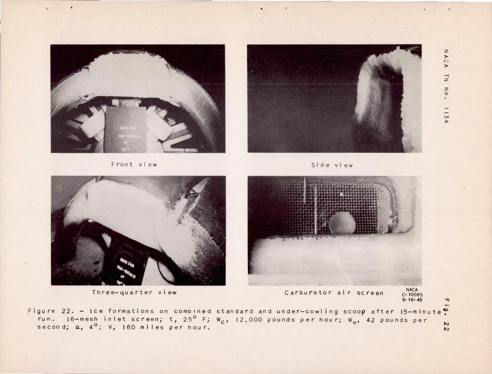
In order to demonstrate analytically the inertia- separation l'r.Lncl)le of the under- cm-Tling scoop, a hypothetical field of two·· climensiomll potent1.al flow was selected to represent approximately the flo,,' abead of tbe engine cm-rling and the paths of 15- and 40-micron diameter droplets were calculated and plotted . The streamHne paths selected were rectangular hyperbolas of the type represented by the general equation
IjI == - xy k
where x and yare the axes , lc is an arbitrary consta.nt, and -¥ is the stream function . The cross-secti.onal outline of the undercovTling scoop was superimposed on tbe fie Id. of flow in an arbitrary position selected to illustrate as clearly as possible tbe inertia-8e~aration principle involved .
The method used to calculate the droplet paths is outlined in reference 3 and is based on the following assumptions :
1. The individual droplets wore assumed to be traveling on particul~r streamlines with a free-stream velocity of 300 feet per second at a dist8.nce 4 feet ahead of the engine cowling .
2 . Tbe speed of the droplet was assumed to r emaln constant at a free-stream velocity of 300 feet per second in a direction tangent to tbe original streaxnline 3.t all points .
:3 . The r adius of curvature of the orig:I.nal stree,mline vTaS
alwa.ys used ir:. determlning the centrifugal acceleration on the droplet even though the droplet petl had c.eviated considera'Jly from the original streamline .
4 . Stokes ' b.vT was assumed to be valid at t: ese values of droplet Reynolds number .
The norID8.1 velocity of tne droplets was calculated frOID Stokes ' la'iTby
'\-There
u com~onent of droplet local velocity normal to original stream-line, ft/sec
15
I'"" d11 opJ.et radius , ft
v dro~]Bt V9~oc~ty) ft/sec
p. e.bsolu.te air viscosity, Ib- sec/sCI ft
!) streaYJline radius of curvature, f't
Tne droplet ::ieviat~on is then fou:l.d froll the eqnation
vhe:,'e
5 deviation of dl"O:P:'..ct r!ormal to stre ::ml ine , ft
t t~1lJe , sec
Subscripts A end B represent tile 1 t;ni ts of the ~.ncreY.Jent .
In orc.er to ShO'll the ef:'ec"t o:~ d::'op s1ze, the p3.ths of dror-lets of 15- and 40··micron dia:.1ote:' 1'91"e ~'lottec1. as SflO"iv:c. in figure 23 . As incUceted by these paths , onlJ' t:te r.:mell tiro:::,lets enter t.le scoop . EYi1en~e of the er_tre.uce of s~all dro,leto into the u:lder-covrling scoo]1s "ras found in tne pre2sr:..ce of liGnt to rJoders.te ice accrotions on t~e insic.e u~_er surface of the inlet d~ t ~nd ir:.. the small amoQ~t of water iClgested b~- the ~Joclified l.U1der-cm·i!.iI\.:, scoop . On tlJe b'1sis of worl~ dO~le -oy IJr . Irvin,; Lang.L:n.l.i:..' of t~1.e General Electric Co . on the pe.ths of \orater d.r0:blle·Gs at values of c.ro:::,let :l:1eyno::"ds number beyond tbe r nnc;o of validl ty of Stokes ' l".vT; it is est~.mQted.. t ::at the 15- and 40-11licron t1l'o'}let p3.ths as calculetoc. from Stokes' lai-T illey correspond to the true paths of droplets whose diameters are A.~. proximately tw:~ce these vaJ.l1es . Because the me .Jsu.red averege droplet diameter oy VOlll.1TIu IDnY-i!:l l1m in t llese tests vlaS betvTeen 853l1d 120 microns , the droplet paths cl!own in figure 23 (b) :.?robab1y represent tr·'..1.e ::;>aths for tt.e cono.i tions of the tests .
REFEREI~CES
1. Kimball, Leo 3 .: Icing Tests of A~.rcl~e.ft-Engine Induction Systems . NACA P.RR , Jan. 1943 .
16
..
.--- --_. - - ---.---
F.'\CA TIT no . lJ.3~
2 . Corson, B1alce Ii., J r .: The Belt Methoo_ for Measuring Pressure Distribution . NACA ItB, FeD . 1943 .
3 . Stickley, A. R .: Some Remarks on the Physical As-pects of the Aircra.ft Icing Problem . Jour . Aero . ScL, vol. 5, no . 11, Sept . 1938, pp . 442-446 .
17
Z\L\-\-748
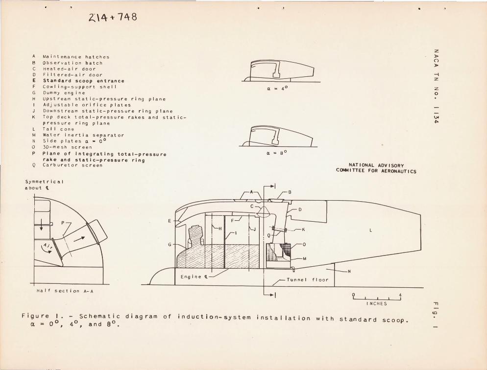
A Maintenance hatches
B Observat i on hatch CHeat ed-a i r door D Filtered-air door E Standard scoop entrance F Cowl ing-support snell G Dummy engine H upstream static-pressure ring plane
Adjustable orifice plates Downstream static-pressure ring plane
cor:---? a 2 4 0
K Top deck total-pressure rakes and static-pressure ring plane
L Tall con!! M Water inertia separator N Sideplatesa-O o
o 30-mesh screen
P Plane of Integrating total-pressure rake and static-pressure ring
Q Carburetor screen
Symmetrical
about {.
o
Ha I f sect ion A-A
E
G
Figure I. a ;: 0°,
Schematic diagram of 4°, and ea.
n~ a .. SO
Engine Cl T1Jnnei floor
NATIONAL ADVISORY COMMITTEE FOR AERONAUTICS
L
N
o 4 , , INCHES
i n d u c t 1o n- S'y s t em nstallation with standard scoop.
z }>
() }>
-i z
z o
\)j
~
"TI
(C

........ ..... NACA C - 151S5 6 - 17-46
Figure 2. - Installation of induction-system test setup in icing research tunnel.
z » ()
» -t z
z o
Vol ~
" ID
N
NACA TN NO. 1134
. N
I ---mr
+ To t ra p
(al Water rake.
Tube-ent rance-t ip cross section I scale: 3" - 1"1
Fig. 3
From rake
To burette
(bl Water trap.
NATIONAL ADVISORY COMMITTEE FOR AERONAUTICS
Figure 3. - Free-water sampling rake and water trap.

NACA TN No. 1134
I a ) Standard scoop.
Ib) under-cowling s coop.
Fig. 4
NACA c· 11955 8· \7.45
I c) Combination of standard and under-cowl i ng scoops. door. )
(Arrow shows inlet
Figure 4. - Basic d e sign of standard and under-cowling scoops.

•
N ACA TN No . 1 134
---------- ---
"I"--_~~f---- l. S" ~
c-c
B- B
A-A
Ld f
Fig. 5a
~-------------14.37·--------------~
---1 __________ - ------ Eng I net ----------------
la! Sta n dard scoop.
NATIONAL ADVISORY COMMITTEE FOR AERONAUTICS
Figure 5. - Profi les and typical cross sections of standard scoop, under-cowling scoop, modified under-cowling scoop, and combination of standard and under-cowl ing scoops.
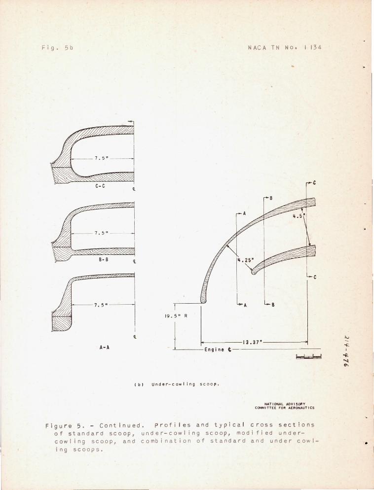
Fig. 5 b N AC A TN No. I 134
L~ La
""U E'9 - j-n-e-t--. 13.37' ----__ .--., __
I bl Under-cowl ing sc oo p.
NATIONAL ADVISORY COMMITTEE FO~ AERONAUTICS
Figure 5 . - Continued . pro fi les and typical cross s e ctions of standard sco o p, under-cowl ing sc oop, modi fi e d undercowling scoop, and combination of standard and under cowling scoops.
•
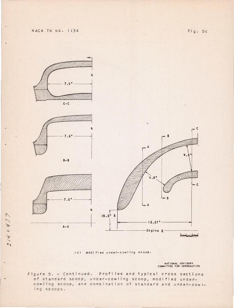
NACA TN NO . 1 134 Fig. 5 c
c-c
•
8-8
19.5- R
A- A 1 ~----------13.37·------------~
~.---------En gin e t ---------------g.., I d
(c) Modif i ed under-cowling scoop.
NATIONAL ADVISORY COMMITTEE FOR AERONAUTICS
F ig ure 5. - co nti nued. Prof i les a nd typical cross sections of standard scoop , under-cowling scoop, modified undercowling scoop , and comb ination of standard and under-cowling scoops.
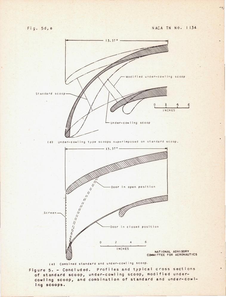
Fig.5d,e N AC A TN NO. 1 134
13. 37" ----------------------~
Modified under-cowling s c oo p
Standard
o 2 4 6 I I ! !
INCHES
Under-cowling scoop
( d) und e r- cow ling type scoops superimposed on standa r d scoop.
Sc r een
~------------------ 13.37"----------------------~
II II"...
Ij "'----Door in II
open pos ition
II , - , , , II
II /1
II 1/
II II
II
1/ '/ 'I I,
, /' " o 2
in closed positi on
4
I NC HE S
6
NATIONAL ADVISORY COMMITTEE FOR AERONAUTICS
'e} Comb i ned standard and und er-cowl i ng scoop .
Figure 5. - Concluded. Profiles and typical cross sections of standard scoop, under-cowl ing scoop, modi fied undercowling scoop, and combination of standard and under-cowlIng scoops.
-------- ------~---------------------.~
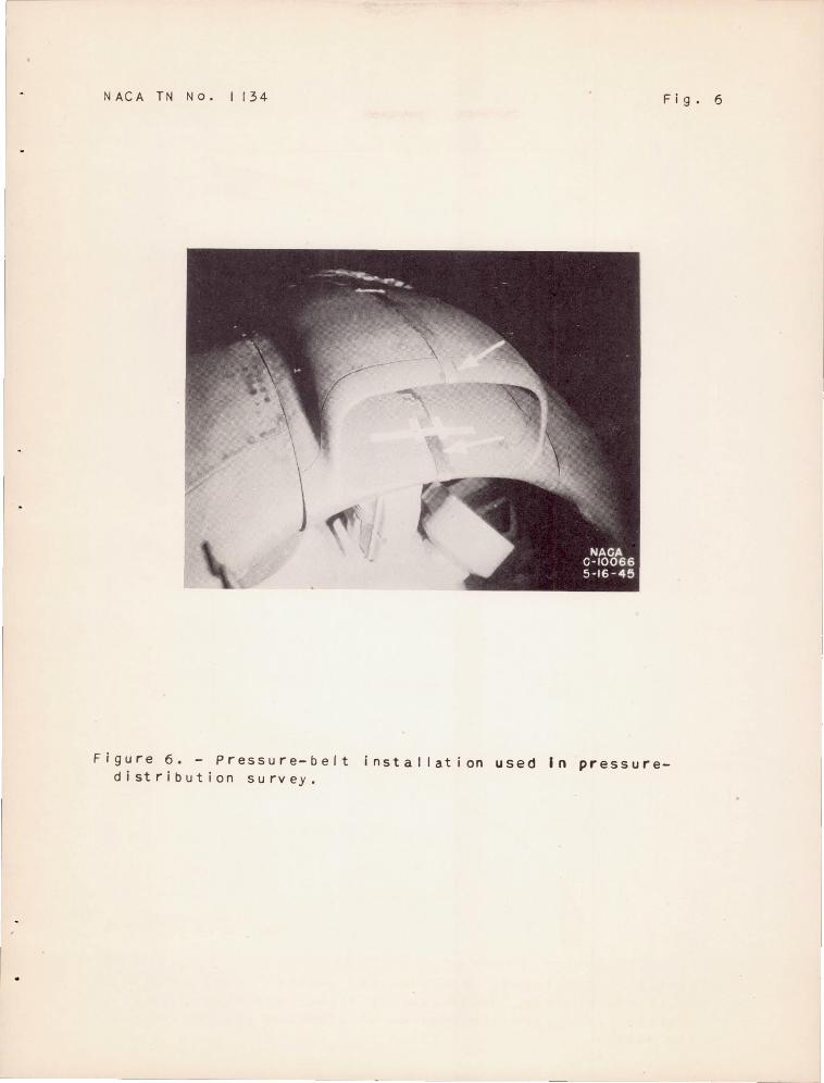
NACA TN No. 1134 Fig. 6
Figure 6. - pressure-belt installation used In pressuredistribution survey.


N AC A TN N O, I I 34
~ v Wc Ie (deg) (.ph) ( I b/hr) (Ib/sec)
a 4 160 7,000 26 o 8 160 12 .000 42 + Positive static pressure - Negative sta t ic pressure
figure 7 . - Surface pressure distributions over standar d scoop .
Fig, 7
5 • 1. 0
NATIONAL ADVISORY COMMITTEE FOR AERONAUTICS
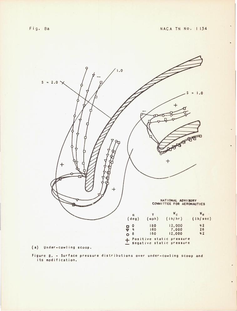
Fig. Sa
(a) Under-cowl ing scoop.
a ( deg)
o 0 V 14 o 8
NACA TN No. 1134
1.0
+
----/ NATIONAL ADVISORY
CtNMl1TEE FOR AERONAUTICS
180 160 160
12,000 7,000
12,000
We {Ib/sec}
142 26 142
~ Positive static pressure Negative static pressure
Figure 8. - Surface pressure distributions over under-cowling scoop and its modification.
--- - -"-'-'- -_. - - _._- ----
NACA TN N o. 1134 Fig. 8 b
S - 1. 0
Cl , We
(d •• ) 'a,h) (Ib/hr) We
(1~/sec)
0 " + 'o.ltln - "e.ativi
(b) Modlfl.d under-cowling ICOOp.
180 7000 28
.tat I c pr",lIr. stat j c pr ••• ure
NATIONAL ADVISORY COMMITTEE FOR AERONAUTICS
Figure 8. - Concluded. Surfae. pre.sllr. distributions over undercowling scoop and It I aodlflc atlon.
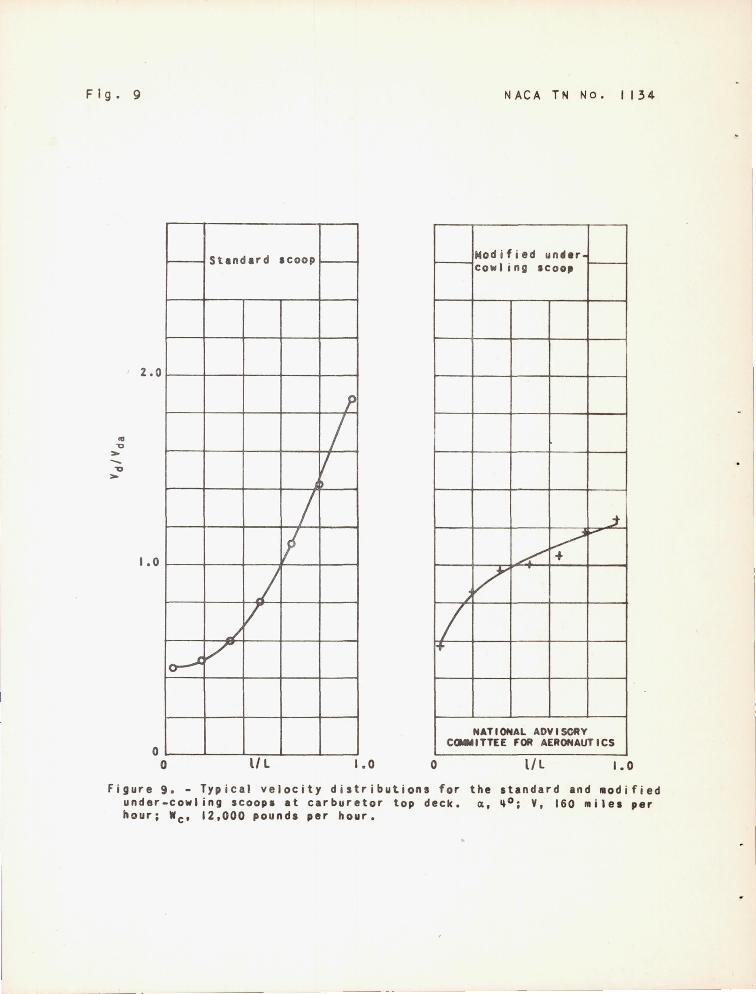
Fig. 9
'" "1:)
> -"'0 >
-
2.0
1.0
10--'
o o
Standard scoop
/ II
J V
,..I
/
II L
N AC A TN No. I 134
Modified un .. ., cowling scoo,
f
/ V
.:t
~ ......
~
~V /
I~
NATIONAL ADVISORY COMMITTEE FOR AERONAUT ICS
1.0 o II L 1.0
Figure 9. - Typical velocity distributions for the standard and ~odified under-cowling scoop. at carburetor top deck. ~. ~o; Y, 160 ~iles per hour; Wc. 12.000 pounds per hour.
. I
NACA TN No.1 134 Fig. 10
.. c
'" ~ ~
8 --!I~
I ... '--:-
~
'" > 0 u ~
~ " III 1/1
~ .. I • ..
a:
100
so
60 0 X
40
20 o (a) a. 00 •
100
so
60 0 X
+ 40
0
100
SO
60
0 x
40
20 0
(c) Cl • SO.
NATIONAL ADVISORY - COMMITTEE FOR AERONAUTICS .......
........ .......
...... ...-.......... ""- ,......-Scoop -• ..a.. -Standard '\
Under-cow II ng \
\ 1)(
MOO 10,000 15,000
~-~ - ---........... -- ............... r...... k... -- ......... ,...
Scoop " " Standard
" Under - cow I I ng Modlflod under-
cow I I ng
5000 10,000 15, JOO
..... -- , "- --r--...... ~ 1'-. .... f', ~
Scoop 0........... Standard ~
r-........ Under-coif I I n9 . r......... ~ ......
rooo 10, ;)00 I~, lOO Charge-air flow, Wc ' Ib/hr
Figure 10.- Variation of ru-prellur. recovery Iflth charg.-alr flow for three scoopa. V, 160 .llea per hour.
Fig, I 1 NACA TN No. 1134
.. c C» U L. C» a.
..
100
o 80 o .-4
~ to
""0 :x: ....
::a:
>L. C» > o u C» L.
C» L. ~ til til C» L. a. , E to
0::
60
40
20
o
NATIONAL ADVISORY COMMITTEE FOR AERONAUTICS
SCOOp Wc (1b/hr)
Standard 7,000 - - - --Standard 12,000 -- -Under-cowl i ng 7,000 ----Under-cowl ing 12,000
r--- 1--- f--- I-- - r-- - -- r-- - -- ---.---~- --- r-.:::--" ~ --..,.:::; .......... V I', ~ ~, ----",- " ,'" , .....
~ ,
/' ~ ... , ,
... , ~/ \
\
V \
\
o 2 4 j
Angle of attack, 4, deg ~lr
Figure 11.- The effect of change in angle of attack on ra~-pressure recovery for standard and under-cowling scoops. V, 160 ~i1es per hour.
J

NACA TN NO. 1134 Fig. 12
NATIONAL ADVISORY COMMITTEE 'OR AERCNAUTICS
500
oJ
L V-
I D L
lL V L
0 / V 400
V J L I cV V
J L c
E 300 --E
'" L-
0>
V li' V 1
I / V "0 W .... CI)
W 01 c
1/ V / / I II V L
L-a>
+"' 200 '" ~ / / V
/
VI V V P / pi V V II V We
Scoop (deg) (lIIph) ( I b/hr)
~V / o Standard 8 160 12,CXD o Standard 4 160 7,cm
II ~.;! )( Standard 0 200 12,<00 + t.t.:>dified 4 160 7.C1YJ
under-
1/V cowl ing /
100
:IZ V
~ V o ~
o 3 6 9 12
Free-water concentration, gra~fmeter3
figure 12. - Relation betwean free-water content and rate of water ingestion in standard and ~odified under-cowling scoops.

0
1
2 c
; 3 c
~ 4 <II .. c QI u 5
QI c c 6 :> .. E 0 7 ~ ..... QI U 8 c to .. ",
0 9
10
11 o
NATIONAL ADVISORY COMMITTEE FOR AERONAUTICS
1/-.....-< k'\
C ~ ~
A LDcat i on
I---
c
Q)
c
.3
4
5
6
7
8
[& V
I~ I\, , I ~ \ 1\ " t;Y ~ I
[\.
\ '\ \ \ 1\ ..
of scoop ~ Scoop location,
I~
1 \ 1. ~
'\ 1\ \ ~ K /' l"-
\ l \ ~ ~~ V
'"
1\ \ ,
Average water concentration
\ 1 1\ ahead of scoop (gram/meter.3)
0 .3.1 \ "\ o '6.5
A 9.0
4 8 12 Water concentration, 9ram/meter.3
(a) Standard scoop.
... Q) ..... c Q)
u 1
<II c
~ 1 ..... E o I.... 1 ..... Q)
~ 1
'" ..... '" ;;1
1
1
9
0
1
2
"1
4
5
5
outer lip
..
j J IJ ! .1 J
VJ
17 [7 Average water / concentration
I~ V V ahead of sc oop
/ (gram/meter.3) 0 5.\)
/' '" 0 7 • .3 A 11.5
. - . -u Water concentra tion, gram/meter.3
(b) Under-cowl ing scoo p.
Figure 1.3.- Typical spray profiles 17 inches V, 160 miles per hour; Wc ' 7000 pounds per
ahead of standard and under-cowl i ng type scoops. hour.
a., 40 ;
~
f----I
"'T1
<C
V<
:z » o » --i :z
:z o
V< ~
84-4').7
'al Standard &Coop. (bl under-cowling scoop. eel Mod I f l ed under-cow' I n9 sc o op
NATIONAL ADVISORY COMMITTEE FOR AERONAUTICS
Figure 14. - Cross sections of scoops showing typical ice formations.
z > n >
-i z
z o
V4 ~
"'Tl
<0
~


T h r e e- qua r t e r v lew
S ide view Ca rburetor ai r screen
( a ) <x, So; V , 160milesperhour .
F igur e IS. G laz e- ic e f o rmati ons on stand ard scoop afte r I S-minut e run.
We' 12 , 000 pounds per hou r; We ' 4 2 pounds per seco nd.
NACA C· 10051 5· 16·45
t, 25 0 F ;
:z » o »
-i :z
:z o
~
~
" <0
U1 I»

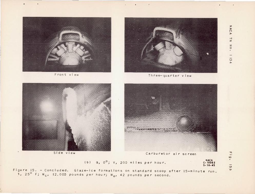
Figure 15. t, 25° F;
Front vi ew
( b )
Three-quarter view
Carburetor air screen
CI.., 0 0 ; V , 200 mi les p er hour. NACA
C· 10052 5· 18 · 45
- Concluded. Glaze-ice formations on standard scoop after
pounds per houri We' 42 pounds per second.
15-minute ru n • We' 12, a 00
z > o > -i z
z o
~
~
" (0
IJ1 C7
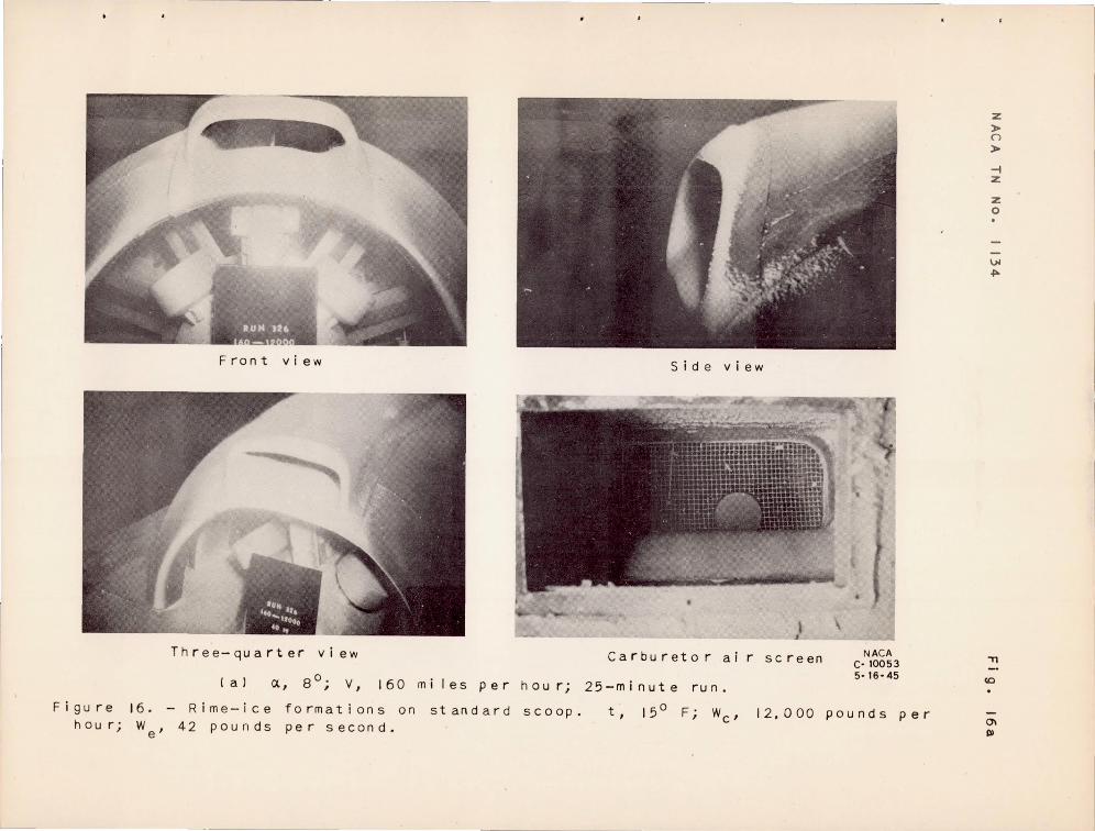
Figure h ou r j
16.
We'
Front vi ew
Three-quarter view
Side view
Carbu reto r ai r sc reen N ACA C· 10053 5·16·45
(aJ ct, So; V, 160 mi les per hou rj 25-minute run.
Rime-ice 42 pounds
form at ion son per second.
standard scoop. t , 15 0 Fj We' 12,000 pounds per
z > ()
> .... z
z o
VI .po.
" (0
01 I»
I

F ron t view Side view
T h r e e- qua r t e r vie w Car bur e tor air 5 c r e e n
(b) <X. 0 0; V. 200 miles per hour; 12-minute run.
Fig u rei 6 • Con c Iud e d • Rim e - ice form at ion son 5 t an dar d 5 coo p • t , I 50 F i pounds per hour; We' 42 pounds per second.
NACA C· 10054 5· 16· 4S
Wc' 12,000
:z »0 ()
»0
-1 :z
:z o
VJ .,..
"'T1
<0
0\ c:T
2 minutes 4 minutes
8 minutes 10 minutes
Figure 17. progressive formation of rime ice on standard scoop. t, 15° F; pounds per hou r; We' 42 pounds per second; CA, 0°; V, 200 mi I es per hou r.
NACA C· 11958 8-\7·45
WC
,I2,OOO
z > ()
> -i z
z o
V4 ~
-n
<0
-l
Front view
Carburetor air screen
(a) 0:, 8°i V, 160 miles per houri
Figure 18. Heavy clear-ice formations on under-cowling pounds per hou ri We' 42 pounds per second.
--- ---
Side view
NACA C- 10055 5-16-45
25-minute run.
s co op • t, 25° F, Wc ' 12,000
:z > (')
> -i :z
:z o
VI ~
" co
Q)
PI
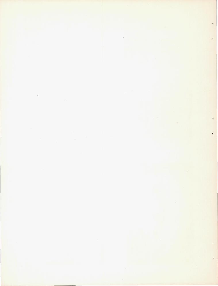
Front view Side view
Inn e r lip of scoop Carburetor ai r
( b) c/.., 0 0 . I V , 190 rn i I e s per h 0 u r; 20-rninute ru n •
Figure 18. Concluded. He av y c I e a r- ice format ion on under-cowl ing
Wc ' 12. 000 pounds per h 0 u r; We' 42 po un d s per second.
NACA sc reen C-l0056
5- 16- 45
scoop. t , 25 0 F· ,
z > n > -i Z
z o
VI ~
"Tl
<0
Ql 0"
I L--
I
F ron t v ie w Si d e v i ew
Inner and outer I ps of sco o p Carburetor ai r screen
( a ) <x , So; v , 16 0 mile s per hour; 20 -minute run.
NACA C· 10058 5· 16· 45
F ig ure 19. - R ime-ic e f o r mat i o ns on under-cowling scoo p. per hour; We' 4 2 pou nd s p e r s econd.
t , I 50 F ; Wc ' 12 . '0 00 po un d s
z ~ ()
> -i Z
z o
VI 4>-
"ll
co
10 I»

F ron t v lew Side view
nner ip of s c o op Carburetor air screen
(bl (X, 0 0; V, 200 miles per houri 15-minute run.
Fig u rei 9. - Con c Iud e d • R im e - ice form a t ion son the un d e r- cow lin 9 5 coo p. I 2. 00 0 P 0 u n d 5 per h 0 u r; We' 4 2 p 0 u n d s per sec 0 n d •
NACA C· 10050 5· 16·45
t, 150
Fi Wc'
:z ~ (")
~
--i z
z o
~ ...
"Tl
<0
10 CT
L
4 minutes 6 minutes
10 minutes 16 minutes
Figure 20. - progressive formation of rime ice on under-cowling scoop.
12,000 pounds per hour; We' 42 pounds per secondi ex, SOi V, 160 miles
NACA c·llue e· 17·45
t, 15 0 F; pe rho u r.
Wc '
•
z: » (")
»
-i z:
z: o
\jj
~
."
<0
I\)
o
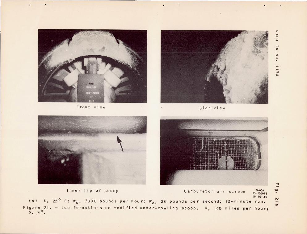
( a ) t,
Figure 21. CJ., 4 0
•
Front view Side view
Inner lip of scoop Carburetor air screen
250
F i
Ice
We' 7000 pounds per hour; We' 26 pounds per second; IO-minute
formations on modified under-cowling scoop. V, 160 miles per
NACA C-IOO61 5- 16-45
ru n •
h OU "';
Z
l> (')
l>
-i z
z o
VI ~
."
'co
t-:>
lit

"
Three-quarter view
Inner I ip of scoop
Side view
NACA C·I0062 5· 16· 45
( b J t, 250 F; W c ' 12 • 000 po un d s per h 0 U r; We' 4 2 P 0 U n d s per sec 0 n d; I 5 - min ute run.
Figure 21. - Continued. per houri Cl, 4°.
Ice formations on modified under-cowling scoop. V, 160 miles
z » ()
»
-1 z
z o
\.N ~
"'Tl
co
I'.l
c:r
l

..
Front view S i de v iew
.\
Inner lip o f scoop • NACA
Car bur et 0 r a Irs c re en C· 10063 5· 16·45
( c) t , 15 0 F; Wc ' 12,000 pounds per hour; We ' 42 pounds per second; 15-minute run.
Figure 21. - Concluded. per hour; 0:, 4°,
Ice formations o n modifi e d under-cowling scoop. v , 160 miles
z » n > -I z
z o
\.>I .j:>.
., co
N
o
I .1
Front vi ew
T h r e e- qua r t e r view
Figure 22. - Ice formations on combined run . 16-mesh inlet screeni t, 25 0 Fi second; 0.,4 0
; V, 160 miles per hour .
Side view
Carburetor ai r screen NACA c· 10065 5· 16'45
z »()
»-
-t z
z o
\.iI ~
" standard and under-cowl ing scoop after 15-minute~
We' 12 ,0 00 pounds per hour; We' 42 pounds per tv
tv
-.,

'-
y
24. ---Streaml ines ---'Oroplet paths
20
I 7'/ < I I. J A 11.6
-- ------t-- -1--=-
-72
56 52 48 44 40 36
(a) water droplets. 15-mieron dlueter.
32 28 24 20
In.
Engineq.
16
NATIONAL ADVISORY COMMITTEE FOR AERONAUTICS
12 8 4
figure 23. - Theoret ieal paths of water droplets and strealll ine flow of the type., • -xy wi th the out I joe of the under-cowl ing seoop arbi trari Iy super i mposed. Vo. 300 feet per second.
8
.4
x
z > ()
> -l z
z 0
\)I
~
"T1
co
N \)I
I»
-----~ '- '-~-----
~

x
y
~ I ,
--- streuli nes ------ Droplet paths
.,----...- ----, 24
20
l/F I/V/T J -3~ __ - ---+---r-Y v-~ --- -----~~~
I I I += t -72 F + =f--- t- .- I-
56 52 48 44 40 36 32 28
In,
Engine {
(b) later droplets. 4O-micron dia~eter.
24 20 16 12 8 4 0
__ J NATIONAL ADVISORY
CCMotITTEE FOR AERONAUTICS
Figure 23 . - Concluded. Theoretical paths of water droplets and streaml ine flow of the type, - -.y with the outl ine of the under-cowl ing scoop .rbltr.ri Iy superimposed . Vo . 300 feet per second.
r
16
12 -=
8
4
x
"T1
to
I\)
V4 CT
z » ()
» -1 %
z o
V4 ~
•

![Electrical Machines Laboratory - Terco [English]...Induction Motor Squirrel Cage 10 Induction Motor Thermistor Protected 32 Laboratory Flexes with Safety Plugs 15,46,47 Load Capacitor](https://img.dokumen.tips/doc/110x75/6093fca788537a39d95478b2/electrical-machines-laboratory-terco-english-induction-motor-squirrel-cage.jpg)


![Numerical Methods for Identification of Induction - [email protected]](https://img.dokumen.tips/doc/110x75/620736f049d709492c2f170f/numerical-methods-for-identification-of-induction-emailprotected.jpg)