Embed Size (px)
Citation preview

Seventh International Conference on CFD in the Minerals and Process Industries CSIRO, Melbourne, Australia 9-11 December 2009
Copyright © 2009 CSIRO Australia 1
DEVELOPMENT OF A NOVEL HYBRID DISCRETE PARTICLE - IMMERSED BOUNDARY MODEL FOR FLUIDIZED BED MEMBRANE REACTORS
J.F. DE JONG, H.J. VAN GERNER, M. VAN SINT ANNALAND and J.A.M. KUIPERS
Fundamentals of Chemical Reaction Engineering, Faculty of Science & Technology, University of Twente,
P.O.Box 217, 7500 AE Enschede, THE NETHERLANDS
ABSTRACT In recent years many different types of fluidized bed membrane reactors have been proposed, for example for the production of ultra-pure hydrogen. For the development and optimization of these novel fluidized bed membrane reactors, fundamental knowledge on the effect of the presence of – and permeation of gas through – the immersed membranes on the hydrodynamics and heat and mass transfer characteristics of the fluidized bed is essential, yet largely lacking in the literature. In this work a hybrid 3D soft-sphere Discrete Particle - Immersed Boundary Model has been developed to investigate the hydrodynamics in great detail, specifically focusing on bubble formation/annihilation close to the submerged membranes, bubble size distribution and particle mixing as a function of the permeation ratio. In this paper, the details of the numerical implementation of the immersed boundary method are described and validated, and first results on the effect of gas extraction and gas addition through the membranes on the fluidized bed hydrodynamics are presented.
NOMENCLATURE AD Reference area (frontal area) [m2] CD Drag coefficient [-] dp particle diameter [m] D diameter of cylinder [m] F force [N] FD Drag force [N] g gravitational constant [m/s2] h characteristic length of a gridcell [m] H height of cylidner [m] mi mass of particle i [kg] M Mixing index [-] Nfp total number of force points [-] Npart total number of particles [-] p pressure [Pa] Re Reynolds number [-] ri position of particle i [m] rij/rik distance between particle i and particle j or k [m] Sf→p source term fluid-particle interaction [kg.m-2s-2] Sf→w source term fluid-wall interaction [kg.m-2s-2] t time [s] u superficial gas velocity [m/s] vi velocity of particle i [m/s] Vi volume of particle i [m3] β interphase momentum transfer coefficient [-] δ Dirac function [-] Δt time step simulation [s] εs/g solids-phase / gas-phase volume fraction [-] μ dynamic friction coefficient [-]
ρg gas-phase density [kg/m3] τg gas-phase stress tensor [kg.m-1s-2]
INTRODUCTION Fluidized bed membrane reactors are gaining worldwide interest. The utilization of membranes makes it possible to overcome equilibrium limitations of reactions, thus resulting in higher reactant conversions and product yield. In contrast to fixed bed membrane reactors, fluidized bed membrane reactors avoid inefficiencies associated with concentration polarization or problems due to hot spot formation during operation. These advantages have clearly lead to an increasing number of applications in various fields.
Adris et al. (1991), who patented a reactor concept for selectively removing hydrogen from a fluidized bed for methane steam reforming, as well as Mlezcko and co-workers (Mleczko et al., 1996), who extensively studied the partial oxidation of methane and compared it to packed bed reactors, were among the first in this field. Several researchers (Grace et al., 2005; Chen et al., 2008; Patil et al., 2007, Gallucci et al., 2008) continued to explore the subject of hydrogen production in the bubbling/fast fluidization regime, employing mainly phenemenological models in combination with experiments. Other application areas include methanol synthesis (Rahimpour et al., 2008), the oxidative dehydrogenation of ethane (Ahchieva et al., 2005) and the partial oxidation of methanol to formaldehyde (Deshmukh et al., 2005a).
While above-mentioned studies mainly focus on the development of novel membrane fluidized bed reactor concepts, another driver to study immersed objects in fluidized beds is fluidized bed combustion. Already in early years heat transfer with cooling tubes inside these fluidized beds were investigated by Sitnai et al. (1981), Yates et al. (1990) and Hull et al. (1999). This research has later been extended with predictions by continuum models (He et al., 2004) and Discrete Particle Models (Gui et al., 2008). However, this research does not include permeation of gas through the tubes. The best experimental approach to mimic membranes for gas addition inside a fluidized bed so far, is to consider distributed feed. Abashar et al. (2008) demonstrated that - apart from safer reactor operation - the distributed feeding of oxygen can lead to a substantial increase in hydrogen yield.
Despite the many fluidized bed membrane reactors currently under development, hardly any detailed understanding of the effect of membranes inside a fluidized bed exists; the majority of current research relies

Copyright © 2009 CSIRO Australia 2
on experimentally aquired data and on phenemenological models, which make use of empirical correlations that neglect the influence of internals. Since good closure relations have a big impact on the predictive nature of phenemenological models, detailed knowledge about the fluidized bed hydrodynamics and the effect of the presence of - and permeation through - membranes is essential. Deshmukh et al. (2005a,b) has made great advances with respect to the effect of the permeation rate on the gas backmixing and bubble-to-emulsion phase mass transfer rate. With ultrasound gas tracer experiments, they showed that due to the presence of the membranes and to the permeation of gas through the membranes, macroscale circulation patterns could be eliminated, resulting in a near plug-flow behaviour of the reactor. They also found smaller average bubble diameters for higher permeation ratios relative to the total gas flow. Christensen et al. (2008) went further into the fundamental research of distributed feed, confirming that such systems indeed lead to a decrease in bubble size and bubble holdup, and therefore to an increase in the total number of bubbles. They also investigated the influence of internals by employing a discrete particel model, in order to improve the closure relations needed for phenemenological (and continuum) models.
This paper aims to further narrow the gap between application and theory, and to discover the fundamental aspects that influence fluidized bed membrane reactor operation. A Discrete Particle Model (DPM) is used in combination with an Immersed Boundary Method (IBM) to study the behaviour of the gas in the immediate vicinity of the membranes. The implementation of the IBM will be described in detail in the following section. Subsequently, the model will be validated and some first results will be discussed. Especially the bubble size distribution is of importance, as is particle and gas mixing as a function of both particle properties and operating conditions.
MODEL DESCRIPTION For the modelling of fluidized beds, various types of Computational Fluid Dynamics (CFD) models have been developed. This work uses the Discrete Particle Model (DPM), in which Lagrangian tracking of single particles is combined with a continuum description of the gas phase. Since the grid size is larger than the particle size, the interaction between gas phase and particles remains unresolved and is modelled via a drag closure relation. Because the model uses a fixed Carthesian grid, calculation times are small compared to models using unstructured or conformal grids, while randomly shaped objects can easily be added by using an Immersed Boundary Method (IBM). The DPM gives sufficient detail to understand the underlying phenomena, yet allows for much more particles than with fully resolved simulations.
Discrete Particle Model In the DPM, all particles are tracked individually using Newton's second law, where vi is the velocity, mi the mass and Vi the volume of particle i:
( ) icontactiigs
ii
ii FgmvuVpV
dtdvm ,++−+∇−=
εβ (1)
The forces on the right-hand side represent the pressure gradient, drag force, gravity and collision forces
respectively. The interphase momentum transfer coefficient β is frequently modelled by a combination of the Ergun equation and the Wen & Yu correlation, but in this model the improved drag relation by Beetstra et al. (2007), based on a direct numerical simulation study, is implemented to account for the gas-particle interaction:
( )( )
5.223
343.01
4
22
Re101
Re4.8331.0
5.1118
180
Re
−
−−
+
++=
++=
+==
gs
sgg
ss
g
sg
sp
B
A
BAd
F
εε
εεε
εεε
εεε
μβ
(2)
The interphase momentum transfer coefficient β depends on the dynamic friction coefficient µ, the gas and solid volume fractions εg and εs, the particle diameter dp and the particle Reynolds number. Particle-particle and particle-wall collisions are calculated with a soft sphere approach, employing a linear spring-dashpot model that distinguishes between sliding and sticking collisions. The gas-phase hydrodynamics are described with a continuum model, and the continuity and volume-averaged Navier-Stokes equations read:
( ) ( )
( ) ( )( ) wfggpfgggs
ggggggg
ggggg
SgSp
uuut
ut
→→ ++−⋅∇−∇−
=⋅∇+∂∂
=⋅∇+∂∂
ρετεε
ρερε
ρερε 0
(3)
where τg is the gas-phase stress tensor and Sf→p the source term due to particle-gas interactions (excluding pressure gradient force). The Eulerian grid and the Lagrangian points are correlated via the porosity using a grid-independent window mapping technique (Link et al., 2005). The additional source term Sf→w signifies the presence and permeation through the membrane and will be discussed in the next section. For a more detailed description of the DPM the reader is referred to a review by Deen et al.(2007).
Immersed Boundary Method The Immersed Boundary Method (IBM), building on the work by Uhlmann (2005), takes into account the presence of - and gas permeation through - cylindrical membranes inside the Eulerian grid by means of a prescribed flux; the transport of gas through the membrane structure itself is not resolved here. The interaction between the Eulerian grid and the immersed object occurs through Lagrangian force points equally distributed over the object's surface. A schematic representation of these force points is shown in Fig. 1. Each force point exerts a force on the gas phase such that the interpolated preliminary velocity up of the gas phase is equal to the specified desired gas velocity ud at the position of that force point. This force (Sf→w) is included as the source term in Equ. 3, and the discretization of this equation at time level n leads to:
( )( )pdnng
nnwf uut
tS −Δ+
Δ=→ βρε1 (4)
using a linear-implicit treatment of the gas-particle drag force. Since the source term is calculated by summing the

Copyright © 2009 CSIRO Australia 3
contributions of all Lagrangian force points (with δ being the numerically approximated Dirac function), the contribution of each Lagrangian force point is simply:
( )
( )( )pfp
dnfp
nfpg
nfpifp
N
iiifp
nwf
uutF
rrFSfp
−Δ+=
−= ∑=
→
βρεφ
δ
,,
1, (5)
The subscript fp (“force point”) denotes that the value of that parameter is obtained using a 4th order polynomial interpolation, given by Deen et al. (2004), from the neighbouring Eulerian cells. The normalization factor φ signifies the relative range of influence of each force point. The factor is defined as the volume per force point divided by the total volume of a grid cell. For a cylinder with diameter D and height H, φ is given by:
fpNhDH2
πφ = (6)
where h is 3 zyx ΔΔΔ and Nfp the total number of force points. Mass is added to (or extracted from) the system by means of four inflow (outflow) cells in the center of the cylinder. The IBM force is added explicitly. Therefore, after a converged pressure correction, the solution shows a small deviation from the prescribed conditions. This numerical error can be minimized by using an iteration until the solution has converged. However, for systems without large fluctuations, this method is expensive due to the need for repetitive solution of the time-consuming pressure correction equation. Instead, a different method is used, which does not calculate the entire IBM force, but only calculates a correction to the solution obtained in the previous time step.
Collisions between particles and the immersed object are treated in the same way as any other collision between particles and walls.
Figure 1: Schematic illustration of the cylindrical membrane with force points inside a computational domain.
RESULTS As a first step, the implementation of the Immersed Boundary Method in the Discrete Particle Model has been validated.
Model Validation Because of the iterative pressure correction of the flowsolver, the prescribed gas velocity on the force points is slightly altered from its prescribed value. This error can simply be decreased by setting the flowsolver’s convergence criterion more stringently.
For different Reynolds numbers, the gas flow around the membrane without the presence of particles with a no-slip boundary condition at the membrane wall has been compared. As expected, for low Reynolds numbers (Re<5), a regime of unseparated flow is found as shown in Fig. 2a. At higher Reynolds numbers, two fixed vortices appear that create a backflow of gas towards the cylinder (Fig. 2b). At even higher Reynolds numbers, vortex shedding is observed, as shown in Fig. 2c. Qualitatively, these phenomenon agree with the literature (Faber, 1995). However, the Reynolds number at which the transition of one state to another occurs do not exactly coincide; at Reynolds numbers between 10 and 40, a fixed pair of vortices should appear; in our simulation, the flow at Re=1 and Re=10 is still unseparated. At Reynolds numbers between 40 and 150 laminar vortex shedding should occur, changing to fully turbulent vortex shedding at Reynolds numbers above 300. In our simulation with Re=100, two fixed vortices can be observed. At Re=1000, vortex shedding occurs. First, it should be noted that our DPM code does not include a turbulence model (which is not necessary for fluidized bed simulations in the bubbling regime). Moreover, the domain size used for these simulations is relatively small. Although a free-slip boundary condition was used at the domain walls, the vicinity of the walls has probably restricted the development of vortex shedding.
Figure 2: Flow around the membrane with no-slip boundary condition for (a) Re=0.1, (b) Re=100 and (c) Re=1000.
Copyright © 2009 CSIRO Australia 4
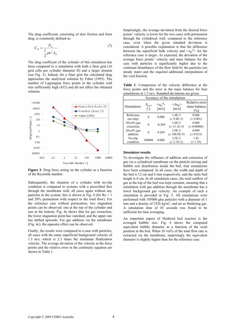
The drag coefficient, consisting of skin friction and form drag, is commonly defined as:
D
DD
Au
FC
2
21 ρ
= (7)
The drag coefficent of the cylinder of this simulation has been compared to a simulation with both a finer grid (16 grid cells per cylinder diameter D) and a larger domain (see Fig. 3). Indeed, for a finer grid the calculated drag approaches the analytical solution by Faber (1995). The number of Lagrangian force points in the cylinder wall was sufficiently high (432) and dit not affect the obtained solution.
Figure 3: Drag force acting on the cylinder as a function of the Reynolds number. Subsequently, the situation of a cylinder with no-slip condition is compared to systems with a prescribed flux through the membrane wall, all cases again without any particles in the system; this is shown in Fig. 4 (for Re = 1 and 20% permeation with respect to the total flow). For the reference case without permeation, two stagnation points can be observed: one at the top of the cylinder and one at the bottom. Fig. 4a shows that for gas extraction, the lower stagnation point has vanished, and the upper one has shifted upwards. For gas addition via the membrane (Fig. 4c), the opposite effect can be observed.
Finally, the results were compared to a case with particles, all cases with the same superficial background velocity of 1.3 m/s, which is 2.3 times the minimum fluidization velocity. The average deviation of the velocity at the force points and the relative error in the continuity equation are shown in Table 1.
Surprisingly, the average deviation from the desired force points’ velocity is lower for the two cases with permeation through the cylindrical wall, compared to the reference case, even when the given standard deviation is considered. A possible explanation is that the difference between the superficial bulk velocity and <ufp
d> for the reference case is larger. As expected, the deviation of the average force points’ velocity and mass balance for the case with particles is significantly higher due to the continual disturbance of the flow field by the particles (no steady state) and the required additional interpolation of the void fraction.
Table 1: Comparison of the velocity difference at the force points and the error in the mass balance for four simulations at 1.3 m/s. Standard deviations are given.
Accuracy of the simulations
Simulation: Npart [-]
<ufpd>
[m/s] <Δufp> [m/s]
Relative error mass balance
[%] Reference (no-slip) 0 0.000 1.4E-3
(± 9.8E-3) 0.006
(± 0.001) 20vol% gas extraction 0 -0.269 3.6E-5
(± 13.1E-5) 0.008
(± 0.00006) 20vol% gas
addition 0 0.269 2.9E-5 (± 108.9E-5)
0.009 (± 0.015)
No-slip condition 100000 0.000 3.5E-2
(± 2.1E-2) 1.82
(± 1.35)
Simulation results To investigate the influence of addition and extraction of gas via a cylindrical membrane on the particle mixing and bubble size distribution inside the bed, four simulations have been compared. In all cases, the width and depth of the bed is 12 cm and 6 mm respectively, and the static bed height is 8 cm. In all simulation cases, the total outflow of gas at the top of the bed was kept constant, meaning that a simulation with gas addition through the membrane has a lower background gas velocity. An example of such a simulation is provided in Fig. 5. All simulations were performed with 105000 glas particles with a diameter of 1 mm and a density of 2526 kg/m3, and air as fluidizing gas. A simulation time of 45 seconds was found to be sufficient for time averaging.
An important aspect of fluidized bed reactors is the averaged bubble size. Fig. 6 shows the computed equivalent bubble diameter as a function of the axial position in the bed. When 10 vol% of the total flow rate is extracted via the membrane, surprisingly the equivalent diameter is slightly higher than for the reference case.

Copyright © 2009 CSIRO Australia 5
Figure 4: Cylindrical membranes inside a flow field without particles at Re=1 with (a) 20% gas extraction, (b) no gas extraction/addition and (c) 20% gas addition through the cylinder’s surface.
Figure 5: Snapshot of the reference simulation with 105000 1-mm red colored glass particles. This is related to the effect of the larger background velocity for this case; above the membrane, the average bubble diameter decreases again due to the gas extraction. In case of gas addition, the effect is the opposite: below the membrane, the bubbles are significantly smaller than the reference case. However, above the membrane the bubble size increases again. Interestingly, the effect of gas addition or extraction on the average bubble size is relatively small for this case with a single membrane tube. In the near future cases with several membranes in different configurations will be investigated.
Figure 6: Time-averaged bubble diameter as a function of the height in the fluidized bed. The static bed height is 80mm.
Fig. 7 showns the time-averaged particle flux. It can be clearly seen that the particle flux below the membrane is signigicantly lower when 30% of the gas is added via the membrane. Most particle movement takes place in the upper half of the bed. When 10% of the gas is extracted, the particle movement is distributed more equally over the bed. It can also be observed that the bed height is higher, a sign for more vigorous particle behaviour.
For the heat- and mass transfer inside a fluidized bed, particle mixing is essential. Several methods to quantify this parameter are proposed in the literature, among others the Average Height Method, Lacey Index and the Nearest Neighbours Method. Due to their grid dependence and sensitivity to macroscopic flow patterns, an improved method, the Neighbour Distance Method, proposed by Godlieb et al. (2007) is used instead. The mixing index M is defined as:
Figure 7: Comparison of the time-averaged particle flux (in kg/m2/s) with (a) 10% gas extraction and (b) 30% gas addition via the membrane.

Copyright © 2009 CSIRO Australia 6
( )
( )∑
∑
=
=
−
−=
part
part
N
ipik
N
ipij
dr
drM
0
0 (8)
where rij is the distance between particle i and its initial nearest neighbour j and rik the distance between particle i and a randomly selected particle k. For different amounts of gas added (or extracted) via the membrane, the time for 95% mixing is displayed in Fig. 8.
Figure 8: Time for 95% mixing as a function of the amount of gas added to the bed via the membrane as percentage of the total flow. Standard deviations are given. A rising trend can be distingished with increasing amount of gas introduced into the system via the membrane, meaning that the mixing becomes worse. This phenomenon can be understood when recalling that by introducing more gas via the membrane, the background velocity is decreased by the same amount to keep the total gas flow rate constant. In small systems the background velocity plays a more pronounced role in particle mixing than the amount of air added or extracted via a single membrane.
CONCLUSION A hybrid Disrete Particle - Immersed Boundary Model has been developed to study the hydrodynamic behavior of fluidized bed membrane reactors. After a model validation some first results have been presented and discussed. The average bubble diameter is mainly related to the local total gas flow rate, at least for the considered case of a single membrane tube submerged in the fluidized bed. Moreover, in a fluidized bed in which the total gas flow rate at the top of the bed is kept constant, extracting gas via a membrane enhances particle mixing due to the larger background gas velocity. Future work will be focused on quantification of the effects of the membranes in terms of closure correlations for phenemenological models.
ACKNOWLEDGEMENTS We gratefully acknowledge SenterNovem, the agency for sustainability and innovation within the Dutch Ministry of Economic Affairs, for its financial support of this project.
REFERENCES ABASHAR, M.E.E., ALHABDAN, F.M. and
ELNASHAIE, S.S.E.H., (2008), “Discrete injection of oxygen enhances hydrogen production in circulating fast fluidized bed membrane reactors”, Int. J. of Hydrogen Energy, May, 33(10), 2477-2488.
ADRIS, A.M., ELNASHAIE, S.S.E.H. and HUGHES, R., (1991), “Membrane reactor for the steam reforming of methane”, Canadian J. of Chem. Eng., October, 69(5), 1061-1070.
AHCHIEVA, D., PEGLOW, M., HEINRICH, S., MÖRL, L., WOLFF, T. and KLOSE, F., (2005), “Oxidative dehydrogenation of ethane in a fluidized bed membrane reactor”, Applied Catalysis A: General, December, 296(2), 176-185.
BEETSTRA, R., VAN DER HOEF, M.A. and KUIPERS, J.A.M., (2007), “Drag force from lattice boltzmann simulations of intermediate reynolds number flow past mono and bidisperse arrays of spheres”, AIChE J., 53(2), 489-501.
CHEN, Z.X., PO, F., GRACE, J.R., LIM, C.J., ELNASHAIE, S.S.E.H., MAHECHA-BOTERO, A., RAKIB, M., SHIRASAKI, Y. and YASUDA, I., (2008), “Sorbent-enhanced/membrane assisted steam-methane reforming”, Chem. Eng. Sci., 63(1), 170-182.
CHRISTENSEN, D., NIJENHUIS, J., VAN OMMEN, J.R. and COPPENS, M.O., (2008), “Influence of distributed secondary gas injection on the performance of a bubbling fluidized-bed reactor”, Ind. & Eng. Chem. Research, May, 47(10), 3601-3618.
DEEN, N.G., VAN SINT ANNALAND, M., VAN DER HOEF, M.A. and KUIPERS, J.A.M., (2007), “Review of discrete particle modeling of fluidized beds”, Chem. Eng. Sci., 62(1-2), 28-44.
DEEN, N.G., VAN SINT ANNALAND, M. and KUIPERS, J.A.M., (2004), “Multi-scale modeling of dispersed gas-liquid two-phase flow”, Chem. Eng. Sci., May, 59(8-9), 1853-1861.
DESHMUKH, S.A.R.K., LAVERMAN, J.A., CENTS, A.H.G., VAN SINT ANNALAND, M. and KUIPERS, J.A.M., (2005), “Development of a membrane-assisted fluidized bed reactor. 1. Gas phase back-mixing and bubble-to-emulsion phase mass transfer using tracer injection and ultrasound experiments”, Ind. & Eng. Chem. Research, August, 44(16), 5955-5965.
DESHMUKH, S.A.R.K., LAVERMAN, J.A., VAN SINT ANNALAND, M. and KUIPERS, J.A.M., (2005), “Development of a membrane-assisted fluidized bed reactor. 2. Experimental demonstration and modeling for the partial oxidation of methanol”, Ind. & Eng. Chem. Research, August, 44(16), 5966-5976.
FABER, T.E., (1995), “Fluid dynamics for phyicists”, Cambridge, UK: Cambridge University Press.
GALLUCCI, F., VAN SINT ANNALAND, M. and KUIERS, J.A.M., (2008), Autothermal reforming of methane with integrated CO2 capture in a novel fluidized bed membrane reactor. part 2: Comparison of reactor configurations”, Topics in Catalysis, December, 51(1-4), 146-157.
GODLIEB, W., DEEN, N.G. and KUIPERS, J.A.M., (2007), “Characterizing solids mixing in DEM simulations”, 6th Int. Conf. on Multiphase Flow, July, Leipzig, Germany.
GRACE, J., ELNASHAIE, S.S.E.H. and LIM, C.J., (2005), “Hydrogen production in fluidized beds with in-

Copyright © 2009 CSIRO Australia 7
situ membranes”, Int. J. of Chem. Reactor Eng., November, 3.
GUI, N., FAN, J.R. and LUO, K., (2008), “DEM-LES study of 3-D bubbling fluidized bed with immersed tubes”, Chem. Eng. Sci., July, 63(14), 3654-3663.
He, Y.R., Lu, H.L., Sun, Q.Q., Yang, L.D., Zhao, Y.H., Gidaspow, D. and Bouillard, J., (2004), “Hydrodynamics of gas-solid flow around immersed tubes in bubbling fluidized beds”, Powder Tech., July, 145(2), 88-105.
HULL, A.S., CHEN, Z.M., FRITZ, J.W. and AGARWAL, P.K., (1999), “Influence of horizontal tube banks on the behavior of bubbling fluidized beds 1. Bubble hydrodynamics”, Powder Tech., July, 103(3), 230-224.
LINK, J.M., CUYPERS, L.A., DEEN, N.G. and KUIPERS, J.A.M., (2005), “Flow regimes in a spout-fluid bed: A combined experimental and simulation study”, Chem. Eng. Sci., July, 60(13), 3425-3442.
MLECZKO, L., OSTROWSKI, T. and WURZEL, T., (1996), “A fluidised-bed membrane reactor for the catalytic partial oxidation of methane to synthesis gas”, Chem. Eng. Sci., June, 51(11), 3187-3192.
PATIL, C.S., VAN SINT ANNALAND, M. and KUIPERS, J.A.M., (2007), “Fluidised bed membrane reactor for ultrapure hydrogen production via methane steam reforming: Experimental demonstration and model validation”, Chem. Eng. Sci., June, 62(11), 2989-3007.
RAHIMPOUR, M.R. and ALIZADEHHESARI, K., (2008), “A novel fluidized-bed membrane dual-type reactor concept for methanol synthesis”, Chem. Eng. & Tech., December, 31(12), 1775-1789.
SITNAI, O., (1981), “Solids mixing in a fluidized bed with horizontal tubes”, Ind. Eng. Chem. Process Des. Dev., July, 20(3), 533-538.
UHLMANN, M., (2005), “An immersed boundary method with direct forcing for the simulation of particulate flows”, J. of Comp. Physics, November, 209(2), 448-476.
YATES, J.G., RUIZ-MARTINEZ, R.S. and CHEESMAN, D.J., (1990), “Prediction of bubble size in a fluidized bed containing horizontal tubes”, Chem. Eng. Sci., 45(4), 1105-1111.

![Structured catalysts and reactors for three phase ... · reactors where the catalyst is part of a packed bed and the membrane has purely a separation role [40]. A more widely used](https://img.dokumen.tips/doc/110x75/5f8abcde2cc6c65a7b1fd378/structured-catalysts-and-reactors-for-three-phase-reactors-where-the-catalyst.jpg)