Embed Size (px)
Citation preview
Composite Structures 97 (2013) 136–146
Contents lists available at SciVerse ScienceDirect
Composite Structures
journal homepage: www.elsevier .com/locate /compstruct
Development and validation of a composite finite element with damping capability
Kenan Y. Sanliturk ⇑, Hasan KorukIstanbul Technical University, Mechanical Engineering Department, 34437 Istanbul, Turkey
a r t i c l e i n f o
Article history:Available online 6 November 2012
Keywords:Modelling damped structuresFinite elementDrilling degrees of freedomComplex eigenvalue problemModal strain energy method
0263-8223/$ - see front matter � 2012 Elsevier Ltd. Ahttp://dx.doi.org/10.1016/j.compstruct.2012.10.020
⇑ Corresponding author. Tel.: +90 2122931300/278E-mail address: [email protected] (K.Y. Sanliturk
a b s t r a c t
This paper presents development and validation of a new composite Finite Element (FE) with dampingcapability. The damping capability is added to the composite shell element with physical drilling degreesof freedom by means of complex element stiffness matrix of the individual layers. The formulation isimplemented in a FE code that allows modelling damped structures and performing modal analysis ofthe resulting complex eigenvalue problem. Some test cases are prepared and frequency response func-tions are measured in order to validate the predictions. The material properties used in the sample struc-tures are identified experimentally using the Oberst Beam Method. Furthermore, the results obtainedusing the proposed composite FE are compared with those based on modal strain energy method. Com-parisons of the experimental and the theoretical results confirm that the damping levels and the naturalfrequencies of damped structures can be predicted with high accuracy using the proposed formulation.
� 2012 Elsevier Ltd. All rights reserved.
1. Introduction
Damping materials are used in many fields including automo-tive, aeronautics, aerospace, acoustics, and domestic appliancesin order to minimise undesirable structure borne vibrations andradiated noise while eliminating high cycle fatigue and failure ofcritical components [1–5]. In such applications, load carryingstructural members, normally made of metallic materials, are usu-ally coated with effective damping materials. Although such treat-ments inevitably cause slight increase in the stiffness and weight ofthe base structure, the increase in the damping capacity of struc-ture is relatively very high.
Accurate predictions of the dynamic properties of compositestructures, especially the damping levels, are quite difficult becauseof inherent coupling between nonlinear material behaviour andother nonlinear effects [6–8]. It is well-known however that if cer-tain conditions are satisfied, structural damping levels can be deter-mined experimentally with good accuracy [9]. On the other hand, asit is not feasible to make prototypes for every possible design or de-sign changes and to test them it is very desirable to simulate designchanges on the computer using reliable models. In most cases, Fi-nite Element (FE) models are used for such purposes.
There are basically three approaches for damping modelling infinite element applications [10], namely; Direct Frequency Re-sponse Method (DFRM), Modal Strain Energy Method (MSEM)and Complex Eigenvalue Method (CEM). In DFRM, FrequencyResponse Function (FRF) matrix is obtained by inversion of the
ll rights reserved.
1; fax: +90 2122450795.).
dynamic stiffness matrix. Then, damping values can be determinedby analysing the FRFs. DFRM is very costly in terms of computationtime as it requires computation of the FRF matrix at individual fre-quencies. Rastogi [11] in his paper evaluated the capabilities andlimitations of the direct frequency response method and modal fre-quency response analysis using a FE program. In MSEM, the eigen-value problem of the actual (damped) system is not solved. Instead,the so-called Normal Modal Analysis of the undamped system isperformed to compute the strain energy ratios for individualmodes in order to estimate the modal damping levels. During thisprocess, it is assumed that the mode shapes of the damped systemare the same as those of the undamped system. Although, MSEMcan be used for modelling complex damped structures, theassumptions associated with this method restrict its applicabilityfor general use. In CEM, on the other hand, the complex eigenvalueproblem is needed to be solved without simplifying assumption.Although CEM [12,13] is a known approach for the predictions ofdamping levels of structures, it has limited applications in practice.
In literature, it is seen that damping levels of structures in gen-eral are either determined by the modal strain energy method[10,14,15] or other formulations that are specifically designed forspecial structures such as beams and plates. For example, Raoet al. [14] in their paper used the modal strain energy method to-gether with FE approach and estimated the modal parameters ofsimply supported damped beams. Zhang and Chen [15] used a fi-nite element procedure based on modal strain energy method forpredicting the modal loss factor of composite beams. Cortés andElejabarrieta [16] formulated a homogenised model for the flexuralstiffness to investigate structural vibration of flexural beams.Moreira and Rodrigues [17] developed a model to simulate the

K.Y. Sanliturk, H. Koruk / Composite Structures 97 (2013) 136–146 137
dynamic response of composite plates. Plagianakos and Saravanos[18] presented a finite element-based formulation for predictingmodal damping and natural frequencies of curvilinear compositeshell structures while modal loss factors are calculated using theenergy dissipation method.
The FE formulation presented here allows modelling dampedcomposite structures and performing modal analyses of the resultingcomplex eigenvalue problem so as to determine modal damping lev-els as well as natural frequencies directly. Also, the complex modeshapes of the structure are obtained directly from the solution ofthe complex eigenvalue problem. This method can be used to modelany structure as it is not restricted to special types of structures orboundary conditions. Also, there is no assumption associated withthe proportionality of the damping distribution within the structure.It is worth stating that reliable and accurate damping predictiontools are still not available in commercial FE packages today.
The outline of this paper is as follows. First, the formulations of aspecial shell element that has physical drilling degrees of freedomfor the rotation in the direction perpendicular to the element nor-mal direction and the new composite element are presented. Thecurrent formulation of the composite element is based on stackingindividual four-noded shell elements on top of each other whereindividual homogeneous layers have different material properties.The damping capability is included in the formulation by meansof complex elemental stiffness matrix representing both the elasticand damping properties of the individual layers of the compositeelement. The composite FE developed here is implemented in a FEcode which allows modelling and analyses of damped compositestructures. Following the formulation and implementation of thecomposite element, the elastic and damping properties of somecommercially available damping materials are determined usingthe Oberst Beam Method in order to obtain properties of the mate-rials to be used in the FE analyses. After that, the performance of theundamped homogeneous shell element is evaluated first. Then, a FEprocedure based on modal strain energy method is utilised to eval-uate the performance of the new composite FE. Finally, the compos-ite FE is validated by comparing the theoretical predictions withexperimentally determined natural frequencies and the associateddamping levels using a few test structures.
2. Formulation of a composite finite element with dampingcapability
Representing multilayer composite structures with an equiva-lent layer is an effective way of modelling multilayer composites[1] as this approach does not increase the number of active DOFsin the model. However, the accuracy of the theoretical model de-pends on how each layer is represented and how the individuallayers are assembled. The formulation of the composite shell ele-ment presented here is based on stacking individual flat homoge-neous shell elements on top of each other. As such, any shellelement can be used to develop the composite element presentedin this paper. However, the specific shell element utilised in thecurrent formulation here has an important feature in the sense thatit has physical drilling degrees of freedom hz in the element normaldirection. This specific homogeneous shell element (Fig. 1) is afour-noded element which is an assembly of the quadrilateralmembrane element with drilling degrees of freedoms [19] andthe plate element [20]. The formulations of the finite elements pro-posed in [19–20] are implemented so as to obtain the element stiff-ness matrix ks. In this paper, this basic shell element is alsoextended for dynamic analysis by computing the element massmatrix ms and also adding damping capability to the element byconsidering the complex Young’s modulus of the material as
E� ¼ Eð1þ jgÞ ð1Þ
where E and g are the Young’s modulus and the loss factor, respec-tively and j ¼
ffiffiffiffiffiffiffi�1p
. The use of complex Young’s modulus results incomplex stiffness matrix k�s for individual elements, a feature neces-sary to develop a composite element with damping capability. It isworth stating here that the composite element proposed in this pa-per is based on the assumption that the matching surfaces of theindividual layers of the composite structure are fully joined to-gether hence there is no rubbing action across the matching sur-faces. Therefore, material damping is considered to be theprimary source of energy dissipation and the use of the complexYoung’s modulus approach is appropriate [1,7,8].
The connectivity definition and the element coordinate systemfor the composite element are shown in Fig. 2. As can be seen, thez-axis defines the element normal direction and the neutral planeis on the x–y plane. Beside the element coordinate system, the def-inition of the properties of the individual layers including thestacking order, layer thicknesses and the corresponding materialproperties are required in composite element formulation. Oneway of defining the stacking order and the corresponding thick-nesses is to define the distance of the top surface of each layer fromthe bottom surface of the composite element, Hi, as illustrated inFig. 3. So the individual thickness ti as well as the distance of themid-surface hi for individual layers can be determined as
ti ¼ Hi � Hi�1; hi ¼ 0:5ðHi þ Hi�1Þ i ¼ 1;2; . . . ;n ð2Þ
In Fig. 3, each layer is assumed to be made of an isotropic mate-rial whose properties can be described by Ei, mi and gi, representingthe Young’s modulus, Poisson’s ratio and loss factor, respectively.The location of the neutral axis depicted in Figs. 2 and 3 are alsorequired to be determined for the formulation of the compositeelement. Although it is not the case for the formulation of thehomogeneous shell element, it is assumed here, only for the pur-pose of determination of the neutral axis, that the plane sectionsremain plane which allows the use of the basic bending formula-tion for the calculation of the distance of the neutral axis fromthe bottom surface of the composite element. This leads to
h ¼ 12
Pni¼1Ei H2
i � H2i�1
� �Pn
i¼1Eitið3Þ
Using h given in Eq. (3), the offset of the individual layers fromthe neutral axis can be determined as
zi ¼ hi � h ð4Þ
After the geometric parameters are determined, the compositeelement is formulated as follows. First, the stiffness and massmatrices for each layer ðk�si;msiÞ are computed as if each layer isoriented on the neutral plane. Then, the stiffness and mass matri-ces are transformed so as to take into account that each layer is off-set from the neutral position by a distance zi. This is performed byusing the relationships between the nodal displacements andforces at the neutral plane and those at the offset location for indi-vidual layers. This can be expressed in matrix form as:
U ¼ TUo ð5aÞ
where
Ui ¼ ½ui v i wi hxi hyi hzi�T ; Uo ¼ ½uo vo wo hxo hyo hzo�T ;
T ¼
1 0 0 0 zi 00 1 0 �zi 0 00 0 1 0 0 00 0 0 1 0 00 0 0 0 1 00 0 0 0 0 1
2666666664
3777777775
ð5bÞ

Fig. 1. Quadrilateral flat shell element with six degrees of freedoms per node.
Fig. 2. Connectivity and geometry definition of the four-noded composite element.
Fig. 3. Geometric definition of the layers.
138 K.Y. Sanliturk, H. Koruk / Composite Structures 97 (2013) 136–146
Here the subscripts i and o denote the locations of the ith layerand the neutral plane, respectively and T is the transformation ma-trix. It is worth stating that although the transformation matrix forelemental forces is slightly different than that shown in Eq. (5), itcan be shown that the stiffness and mass matrices for individuallayers can be expressed with respect to the neutral plane in a con-ventional manner as:
K�si ¼
T 0 0 0T 0 0
T 0T
26664
37775
T
k�si
T 0 0 0T 0 0
T 0T
26664
37775;
Msi ¼
T 0 0 0T 0 0
T 0T
26664
37775
T
msi
T 0 0 0T 0 0
T 0T
26664
37775 ð6Þ
where 0 is a 6 � 6 zero matrix. Finally, the element stiffness andmass matrices for the composite element is obtained by addingthe contributions of individual layers via a summation process as:
K�c ¼Xn
i¼1
K�si; Mc ¼Xn
i¼1
Msi ð7Þ
where the subscripts c above denotes the composite shell. It shouldbe noted that the summation above represents matrix building
rather than simple matrix summation. Once the elemental stiffnessand mass matrices are available with respect to the neutral plane,these matrices are transformed to a common global coordinate sys-tem and the natural frequencies and modal damping values for adamped system can be obtained by solving the standard eigenvalueproblem:
ðK� � k2MÞW ¼ 0 ð8Þ
where K⁄ and M are the system stiffness and mass matrices, respec-tively. It is worth noting here that K⁄ matrix is complex, represent-ing non-proportional damping distribution. The complexeigensolution is obtained here by using Subspace Iteration Method[21] and the solution of the eigenvalue problem above yields
k2r ; Wr r ¼ 1;2; . . . ;n ð9Þ
where k2r and wr are complex eigenvalues and eigenvectors (mode
shapes), respectively. By defining k2r ¼ x2
r ð1þ jgrÞ, natural frequen-cies and loss factors are given as:
x2r ¼ Re k2
r
� �; gr ¼ Im k2
r
� �=Reðk2
r Þ ð10Þ
The formulation presented in this paper is implemented in anFE code FINES [22–23], designed for modelling and analysingdamped and undamped structures. The developed undampedhomogeneous and the damped composite shell elements arenamed 3SHL04 and 3MIC04, respectively. Obviously, the use ofthe shell element having damping capability formulated here

K.Y. Sanliturk, H. Koruk / Composite Structures 97 (2013) 136–146 139
requires the complex Young’s moduli of materials. Therefore, in or-der to validate the composite element developed in this paper,first, modal loss factors and Young’s moduli of some commerciallyavailable damping materials used to prepare test structures areexperimentally determined using a dedicated test method (OberstBeam Method) in the next section.
3. Measurement of material properties using the Oberst BeamMethod
Material properties of individual layers of composite structuresare required in order to validate the composite FE developed in thispaper. It is known that the mechanical properties of commerciallyavailable damping (viscoelastic) materials used for surface damp-ing treatments depend on frequency hence, special experimentalprocedures are needed to identify the properties of these materials.Therefore, a dedicated test method, i.e., the Oberst Beam Method[24,25] is used to determine damping and elastic properties ofthe materials used in this current investigation. For this purpose,Frequency Response Function (FRF) measurements are performedon both bare and damped composite beams at various modes ofvibration using an Oberst test rig (Fig. 4), and the mechanical prop-erties of the materials are determined as outlined in ASTM E756-05standard [25]. In the Oberst Beam Method, bending modes of abeam are measured for the determination of material propertiesat individual natural frequencies. The results of the first bendingmode are not recommended to be used during this process[25,26]. Also, various errors originating from measurement systemand some system parameters are minimised as described in [27] inorder to obtain material properties with high level of accuracy. Theidentified Young’s moduli and loss factors of the steel beam andthe damping materials used in this paper are given in Table 1. Here,the damping (viscoelastic) materials are named as DM-1, DM-2,DM-3, DM-4 and DM-5. As stated before, the materials whosemechanical properties given in Table 1 are used to prepare sometest structures that are modelled using the FE approach for valida-tion purposes as described in the next section.
4. Validation of the homogeneous shell and composite finiteelement
4.1. Evaluation of the performance of the undamped homogeneousshell element
In this section, the performance of the undamped homogeneousshell element developed in Section 2 is evaluated. The structure
Fig. 4. Oberst test rig used for ide
used for this purpose and its material properties are given inFig. 5 and Table 2, respectively. First, using a very fine mesh, i.e.,1 mm element mesh size, the FE models of the plate given inFig. 5 are prepared using the undamped shell element (3SHL04)in FINES and the four-noded (S4R) shell element in ABAQUS pro-gram [28]. Each FE model of the structure has 8241 nodes, 8000elements and 49446 DOFs. It is noted that there are three main dif-ferences between the shell element 3SHL04 and the widely usedelement S4R: (i) unlike the most shell elements available in mostcommercial software, 3SHL04 element used in this paper has phys-ical rotational degrees of freedom (drilling degrees of freedom) inthe direction normal to the surface of the element [19]. (ii) Elemen-tal properties of S4R element [28] are obtained using reduced inte-gration but 3SHL04 is not using reduced integration. (iii) 3SHL04element is valid for both thick and thin plates [20]. Natural fre-quencies, mode shapes and the difference between the results ofthe two programs are listed in Table 3. As seen, almost identical re-sults are obtained using both programs when a very fine mesh isused. Considering these results as the correct or reference values,further analyses and comparisons are performed to evaluate theperformance of the undamped shell element.
The FE models of the structure for fine (5 mm), medium(10 mm) and coarse (20 mm) element mesh sizes are developedagain using both FINES and ABAQUS programs and results are pre-sented in Table 4. Using the correct/reference values of the naturalfrequencies in Table 3, the absolute errors in natural frequenciescorresponding to different mesh sizes are plotted in Fig. 6. Also,for the 2nd, 4th and 7th modes, the predicted natural frequenciesfrom FINES and ABAQUS results as well as the actual (reference)natural frequencies are plotted in Fig. 7. It is seen that the errorsin natural frequencies of all the modes are smaller when the finiteelement developed in this paper is used in models with variousmesh sizes (Fig. 6). FINES predicts the sequence of the modes cor-rectly even when a coarse mesh is used while the 6th and 7thmodes are interchanged when ABAQUS program is used (Table 1).It is clearly seen in Fig. 7 that natural frequencies converge to ac-tual values using less number of elements when the shell elementin FINES is used. By means of drilling degrees of freedom used inthe formulation of the element, FINES model appears to be capableof more accurate natural frequency predictions especially for thosemodes comprising rotations in the normal direction of the individ-ual elements. This is clearly seen in the results for the 7th mode (anin-plane bending mode). For this mode, the errors are 0.3% and1.8% for the cases of fine and coarse meshes, respectively, whenFINES is used. The corresponding errors in ABAQUS predictionsare �0.6% and �12.3%, respectively. Although the results are not
ntifying material properties.
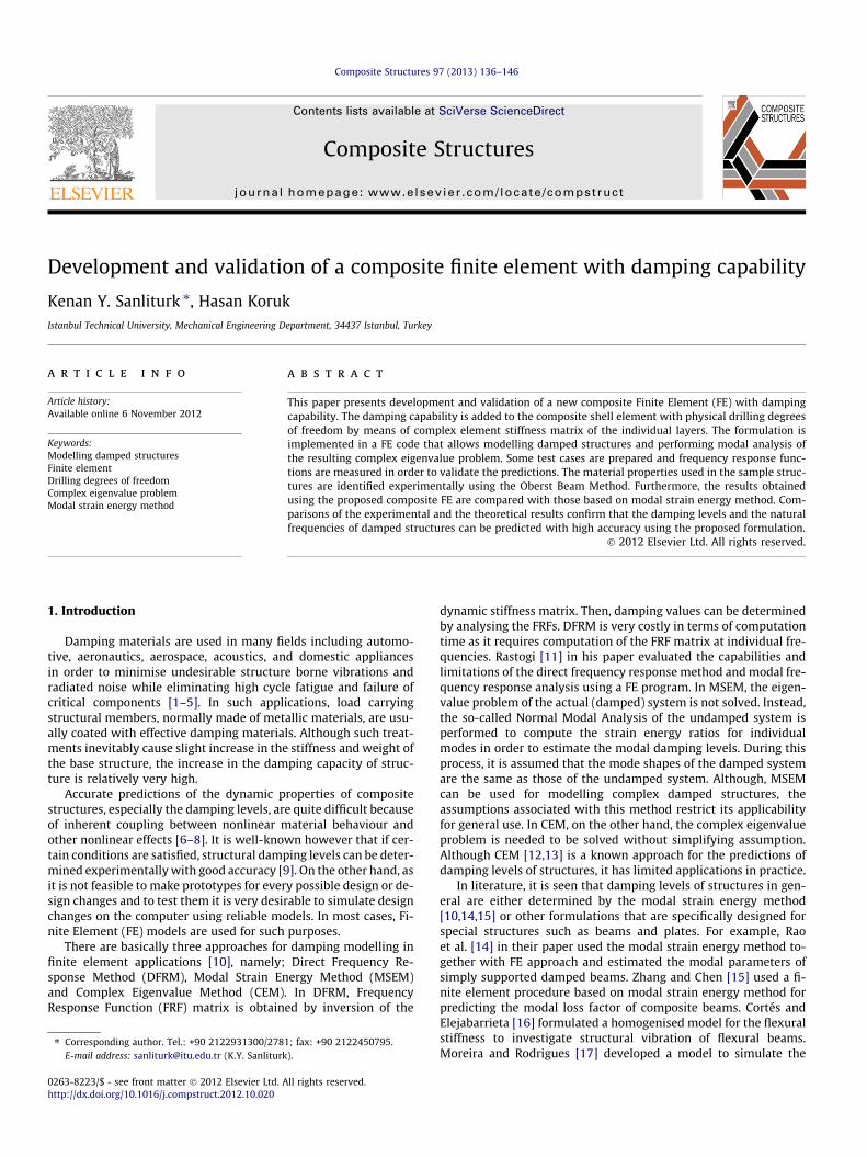
Table 1Identified Young’s moduli and loss factors for steel and damping (viscoelastic) materials using the Oberst Beam Method.
Material Bending mode no. f (Hz) E (GPa) g
Steel 2 107.0 205.9 0.00203 299.0 205.0 0.00154 584.5 204.0 0.00145 966.6 204.2 0.0012
DM-1 2 97.9 1.05 0.333 274.6 1.07 0.434 537.7 1.07 0.51
DM-2 2 102.4 1.29 0.373 286.7 1.30 0.474 548.8 1.13 0.64
DM-3 2 104.0 1.52 0.293 307.7 2.06 0.254 617.6 2.32 0.23
DM-4 2 90.2 0.45 0.433 253.0 0.47 0.50
DM-5 2 92.4 0.54 0.463 260.9 0.62 0.47
Fig. 5. The undamped plate structure (thickness = 1 mm) used in the analyses.
Table 2Material properties of the plate structure.
Material Young’s modulus (N/m2) Density (kg/m3) Poisson’s ratio
Steel 204 � 109 7867 0.3
140 K.Y. Sanliturk, H. Koruk / Composite Structures 97 (2013) 136–146
presented here for brevity, further analyses are also performed forsome other structures and similar results are obtained. All these re-sults show that the undamped shell element developed and imple-mented here has superior performance in predicting modalparameters. In the next section, the performance of the dampedcomposite element developed in this study is evaluated.
4.2. Validation of the composite finite element
In this section, damping levels of some structures are predictedusing the new composite element (3MIC04 in FINES) developed inthis paper and the results are compared with those obtained fromModal Strain Energy Method (MSEM) for validation purposes. Todo this, a FE-based MSEM is utilised using S4R shell elements inABAQUS models. In FE-based MSEM, the base structure and thecorresponding damping layers are tied to each other using appro-priate constraints and Lanczos eigensolver is used for undampedmodal analysis [20]. After performing normal modal analysis, themodal loss factors of the damped structures are calculated by [10]:
gðrÞ ¼ gðrÞd V ðrÞd þ gðrÞb V ðrÞb
� �= V ðrÞd þ V ðrÞb
� �ð11Þ
where gðrÞd and V ðrÞd are the loss factor and the strain energy of thedamping (viscoelastic) layer corresponding to rth mode and V ðrÞb isthe strain energy of the base when structure vibrates at its rthmode.
The plate structures given in Fig. 8 are used in this section in or-der to numerically assess the performance of the new composite
element. The dimensions of the plates are 200 mm and 300 mmwhile the dimensions of the damping patches are 100 mm and200 mm. The thicknesses of both the base and damping patchesare 2 mm. The Young’s modulus, Poisson’s ratio and density ofthe base material are 205 GPa, 0.3 and 7800 kg/m3, respectively,while the corresponding properties for the damping material are2.5 GPa, 0.45 and 2500 kg/m3, respectively. It should be noted thatdamped regions of the structures are modelled using the new com-posite finite elements (3MIC04) while the bare regions are mod-elled by using the undamped shell elements (3SHL04) usingFINES. The natural frequencies and the modal loss factors of theplates predicted via FE-based MSEM and the composite FE basedComplex Eigenvalue Method (CEM) developed in this paper are gi-ven in Table 5. As it is well-known, MSEM can predict damping lev-els of a structure with high accuracy as long as the mode shapes ofthe damped structure are the same or close to those of the un-damped structure. The complex mode shapes for the plates withdamping patches in Fig. 8 are predicted using CEM. It is noted thatthe mode shapes of the structures up to almost a dozen modes areclose to being real mode shapes. The so-called mean angles (U�) forindividual modes -a measure of complexity of the mode shape [29]– are also given in Table 5. The results show that the mean angle isquite small (smaller than 5�), indicating that the mode shapes arealmost real. Therefore, FE-based MSEM is expected to predict thenatural frequencies and damping levels of the structure with highaccuracy. The natural frequencies and the modal loss factors ofboth plates, predicted via the composite FE based CEM developedin this paper and the FE-based MSEM, are compared in Figs. 9and 10, respectively. As seen, the results are nearly the same andmatch successfully. These results confirm that the composite finiteelement developed here predicts the modal parameters of struc-tures with high level of accuracy. In the next section, the predic-tions are compared with experimental results in order to assessthe performance of the composite element in actual cases.
4.3. Experimental validation
4.3.1. Test case I: damped beamsIn this section, a few fully damped beams (used in the Oberst
beam measurements in Section 3) and a partially damped beamare modelled using the composite element developed in this paper,predictions are made and models are validated using measureddata. The so-called fully damped Oberst beam (Fig. 11) is madeby coating a layer of damping material to one side of a bare beam.

Table 3Predicted natural frequencies of the plate structure: Results for very fine mesh.
No. Mode Natural frequency (Hz)
Shape Type FINES ABAQUS Difference (%)
1 1st Bending 20.8 20.8 0.0
2 2nd Bending 130.3 130.3 0.0
3 1st Torsional 206.5 206.4 0.1
4 3rd Bending 365.6 365.7 0.0
5 2nd Torsional 631.8 631.4 0.1
6 4th Bending 718.7 718.9 0.0
7 1st inplane Bending 798.8 799.5 �0.1
8 3rd Torsional 1092.3 1091.6 0.1
9 5th Bending 1191.7 1192.1 0.0
10 4th Torsional 1607.9 1607.1 0.0
Table 4Predicted natural frequencies of the plate structure: Results for various mesh sizes.
Mode no. Mesh size = 5 mm, DOF = 2214 Mesh size = 10 mm, DOF = 630 Mesh size = 20 mm, DOF = 198
FINES ABAQUS FINES ABAQUS FINES ABAQUS
f (Hz) Error (%) f (Hz) Error (%) f (Hz) Error (%) f (Hz) Error (%) f (Hz) Error (%) f (Hz) Error (%)
1 20.8 0.0 20.8 0.0 20.8 0.0 20.8 0.0 20.8 0.0 20.8 0.02 130.4 0.0 130.6 0.2 130.5 0.1 131.2 0.6 131.0 0.5 133.6 2.53 206.1 �0.2 207.2 0.3 204.7 �0.9 207.3 0.4 201.8 �2.3 206.4 �0.14 365.9 0.1 367.3 0.5 366.8 0.3 372.2 1.8 370.6 1.4 392.7 7.45 630.4 �0.2 634.0 0.3 626.1 �0.9 635.5 0.6 617.1 �2.3 635.2 0.56 719.8 0.1 725.2 0.9 723.0 0.6 745.0 3.7 738.1 2.7 832.0 15.87 801.2 0.3 794.2 �0.6 804.1 0.7 776.9 �2.7 813.4 1.8 700.8 �12.38 1089.9 �0.2 1097.3 0.5 1082.5 �0.9 1103.9 1.1 1067.9 �2.2 1115.2 2.19 1194.5 0.2 1209.7 1.5 1203.3 1.0 1265.9 6.2 1246.5 4.6 1531.7 28.510 1604.4 �0.2 1618.6 0.7 1594.2 �0.9 1638.9 1.9 1578.5 �1.8 1692.2 5.2
K.Y. Sanliturk, H. Koruk / Composite Structures 97 (2013) 136–146 141
The dimensions (length and width) of these beams areL = L1 = 220 mm and w = 10 mm, respectively. Thickness of the base(steel) beam is t = 1 mm while the thicknesses (t1) of the damping
materials (DM-1, DM-2 and DM-3 used here) are 2.2 mm. Also, themeasured densities of the steel and damping materials DM-1,DM-2 and DM-3 are 7866.7, 2372.0, 2218.8 and 2312.9 kg/m3,

Fig. 6. Errors in natural frequencies of the plate for fine-5 mm (left), medium-10 mm (centre) and coarse-20 mm (right) mesh sizes.
Fig. 7. Comparisons of the actual natural frequencies of the plate with the predicted results from FINES and ABAQUS programs for 2nd (left), 4th (centre) and 7th (right)modes.
Fig. 8. Plates damped one side (left) and both sides (right).
Table 5Predicted natural frequencies and loss factors of the plates damped one side and both sides using the composite FE based CEM developed in this paper (FINES) and the FE-basedMSEM and mean angles.
Mode no. Damped one side Damped both sides
f (Hz) g (%) U� f (Hz) g (%) U�
FINES MSEM FINES MSEM FINES MSEM FINES MSEM
1 112.5 112.8 3.02 3.04 0.5 115.0 115.3 5.50 5.55 1.02 117.6 117.6 4.74 4.75 1.1 118.4 118.3 8.07 8.11 1.83 245.2 246.0 2.20 2.21 1.4 240.3 240.9 3.91 3.93 2.14 269.0 269.6 3.07 3.10 2.8 265.0 265.4 5.83 5.86 4.25 314.1 315.2 2.01 2.03 1.5 311.7 312.6 3.49 3.53 2.16 367.8 369.3 1.76 1.78 1.6 368.8 370.1 3.04 3.09 2.47 461.7 464.2 2.12 2.12 1.4 455.3 457.5 3.73 3.76 2.58 519.0 521.7 2.19 2.21 1.9 506.3 508.9 3.70 3.73 3.9
Fig. 9. Natural frequencies (left) and modal loss factors (right) of the plate damped one side.
142 K.Y. Sanliturk, H. Koruk / Composite Structures 97 (2013) 136–146

Fig. 10. Natural frequencies (left) and modal loss factors (right) of the plate damped both sides.
Table 6Measured and predicted natural frequencies of a bare steel beam (220 mm).
Bending mode no. fEXP (Hz) fFINES (Hz) fABQ (Hz) gEXP (%)
2 107.0 106.8 106.8 0.163 299.0 299.3 299.3 0.144 584.5 586.9 587.1 0.125 966.6 971.2 972.0 0.11
K.Y. Sanliturk, H. Koruk / Composite Structures 97 (2013) 136–146 143
respectively. The identified mechanical properties of the dampingmaterials are already given in Table 1. Poisson’s ratios are takenas 0.3 and 0.45 for steel and damping materials, respectively. Here,using these material properties, damped beams are modelled usingboth (i) the composite element presented in this paper and (ii) theproposed FE approach based on MSEM. Mesh convergence check ismade and an appropriate mesh size is used for both programs(5 mm mesh size for FINES and 2.5 mm mesh size for ABAQUS).The FE model of the damped beam is created using 2 � 44 compos-ite finite elements (3MIC04) in FINES and each layer of the beam ismodelled using 4 � 88 elements (S4R) in ABAQUS. As each layer ofthe composite structure needs to be modelled separately in ABA-QUS in order to get results via MSEM, even for the same mesh size,the number of element required by FINES will be half of that re-quired by ABAQUS. It should also be noted that only bendingmodes of cantilever beams are measured in the Oberst Beam Meth-od, hence, in this section, predicted and measured natural frequen-cies and loss factors are compared for bending modes only.
First, the measured and predicted natural frequencies of a steelbeam that is used as the base of the damped beams using FINESand ABAQUS programs are compared in Table 6. As can be seen,the predicted results using both methods are very close to themeasured values.
It is known that the material properties of the damping (visco-elastic) damping materials depend on frequency. Therefore, it isnot possible to correctly predict more than one natural frequencyof the composite structures using a single eigenvalue (modal) anal-ysis. Therefore, it is necessary to specify the material properties fora specific frequency range and then perform the modal analysisapplicable to that frequency range only. The frequency range andthe corresponding material properties are changed accordinglyand the modal analyses of the damped composite beams are re-peated until the whole frequency range of interest are analysed.
Experimentally determined and predicted natural frequenciesand loss factors using the composite element developed in this pa-per and the FE-based MSEM for three different damped beams aregiven in Tables 7–9. It is seen that the predicted loss factors and
L1
L
t
t1
Fig. 11. Completely dam
natural frequencies via new composite element are very close tothe experimentally identified values and also to the results of theFE-based MSEM. The results obviously confirm the high accuracythat can be achieved by using the new composite finite elementformulation presented in this paper. It should be noted that theanalysis method based on MSEM is capable of predicting thedamping levels for individual modes of such a structure with highaccuracy even the damping level of the structure is high (e.g.,g = 20%) as long as the mode shape is real or very close to beingreal. The mean angles (U�) for individual modes of the fullydamped beams are given in Table 10. The results show that themean angle is quite small (smaller than 1�), indicating that themode shapes are almost real.
Also, a partially damped beam measured again using the Obersttest rig is modelled and the results are evaluated. Configuration ofthis beam is given in Fig. 12 where L1 = 220 mm, L = 250 mm,w = 10 mm, t = 1 mm and t1 = 2.2 mm. This beam is prepared usingDM-3 material. As before, the damped regions of the beam aremodelled using the new composite finite elements (3MIC04) whileother regions are modelled by using the undamped shell elements(3SHL04) developed. The measured and the predicted results ofthis partially damped beam are listed in Table 11. As seen, the pre-dicted results are very close to the measured ones, demonstratingonce again that the new composite finite element formulation pre-sented in this paper yields high accuracy if the actual (measured)values of the elastic and damping properties of the individualmaterials forming the composite elements are provided.
w
ped (Oberst) beam.
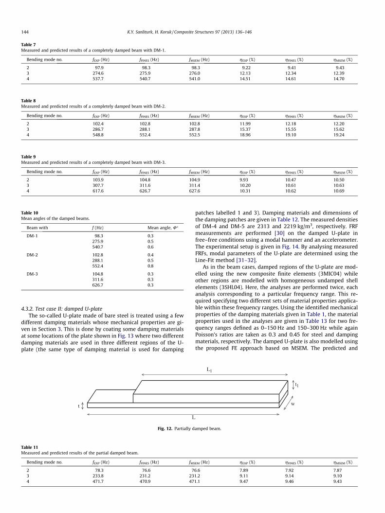
Table 7Measured and predicted results of a completely damped beam with DM-1.
Bending mode no. fEXP (Hz) fFINES (Hz) fMSEM (Hz) gEXP (%) gFINES (%) gMSEM (%)
2 97.9 98.3 98.3 9.22 9.41 9.433 274.6 275.9 276.0 12.13 12.34 12.394 537.7 540.7 541.0 14.51 14.61 14.70
Table 8Measured and predicted results of a completely damped beam with DM-2.
Bending mode no. fEXP (Hz) fFINES (Hz) fMSEM (Hz) gEXP (%) gFINES (%) gMSEM (%)
2 102.4 102.8 102.8 11.99 12.18 12.203 286.7 288.1 287.8 15.37 15.55 15.624 548.8 552.4 552.5 18.96 19.10 19.24
Table 9Measured and predicted results of a completely damped beam with DM-3.
Bending mode no. fEXP (Hz) fFINES (Hz) fMSEM (Hz) gEXP (%) gFINES (%) gMSEM (%)
2 103.9 104.8 104.9 9.93 10.47 10.503 307.7 311.6 311.4 10.20 10.61 10.634 617.6 626.7 627.6 10.31 10.62 10.69
Table 10Mean angles of the damped beams.
Beam with f (Hz) Mean angle, U�
DM-1 98.3 0.3275.9 0.5540.7 0.6
DM-2 102.8 0.4288.1 0.5552.4 0.8
DM-3 104.8 0.3311.6 0.3626.7 0.3
144 K.Y. Sanliturk, H. Koruk / Composite Structures 97 (2013) 136–146
4.3.2. Test case II: damped U-plateThe so-called U-plate made of bare steel is treated using a few
different damping materials whose mechanical properties are gi-ven in Section 3. This is done by coating some damping materialsat some locations of the plate shown in Fig. 13 where two differentdamping materials are used in three different regions of the U-plate (the same type of damping material is used for damping
L
t
Fig. 12. Partially d
Table 11Measured and predicted results of the partial damped beam.
Bending mode no. fEXP (Hz) fFINES (Hz) fMS
2 78.3 76.6 73 233.8 231.2 234 471.7 470.9 47
patches labelled 1 and 3). Damping materials and dimensions ofthe damping patches are given in Table 12. The measured densitiesof DM-4 and DM-5 are 2313 and 2219 kg/m3, respectively. FRFmeasurements are performed [30] on the damped U-plate infree–free conditions using a modal hammer and an accelerometer.The experimental setup is given in Fig. 14. By analysing measuredFRFs, modal parameters of the U-plate are determined using theLine-Fit method [31–32].
As in the beam cases, damped regions of the U-plate are mod-elled using the new composite finite elements (3MIC04) whileother regions are modelled with homogeneous undamped shellelements (3SHL04). Here, the analyses are performed twice, eachanalysis corresponding to a particular frequency range. This re-quired specifying two different sets of material properties applica-ble within these frequency ranges. Using the identified mechanicalproperties of the damping materials given in Table 1, the materialproperties used in the analyses are given in Table 13 for two fre-quency ranges defined as 0–150 Hz and 150–300 Hz while againPoisson’s ratios are taken as 0.3 and 0.45 for steel and dampingmaterials, respectively. The damped U-plate is also modelled usingthe proposed FE approach based on MSEM. The predicted and
L1
t1
w
amped beam.
EM (Hz) gEXP (%) gFINES (%) gMSEM (%)
6.6 7.89 7.92 7.871.2 9.11 9.14 9.101.1 9.47 9.46 9.43
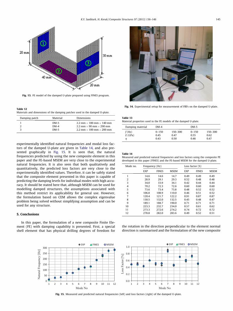
Fig. 13. FE model of the damped U-plate prepared using FINES program.
Table 12Materials and dimensions of the damping patches used in the damped U-plate.
Damping patch Material Dimensions
1 DM-5 2.2 mm � 100 mm � 140 mm2 DM-4 2.2 mm � 90 mm � 290 mm3 DM-5 2.2 mm � 100 mm � 200 mm
Fig. 14. Experimental setup for measurement of FRFs on the damped U-plate.
Table 13Material properties used in the FE models of the damped U-plate.
Damping material DM-4 DM-5
f (Hz) 0–150 150–300 0–150 150–300E (GPa) 0.45 0.47 0.55 0.62g 0.43 0.50 0.46 0.47
Table 14Measured and predicted natural frequencies and loss factors using the composite FEdeveloped in this paper (FINES) and the FE-based MSEM for the damped U-plate.
Mode no. Frequency (Hz) Loss factor (%)
EXP FINES MSEM EXP FINES MSEM
1 14.6 14.6 14.7 0.49 0.49 0.492 28.9 29.1 29.3 0.52 0.48 0.483 34.0 33.9 34.1 0.42 0.44 0.444 70.2 72.3 72.6 0.60 0.60 0.605 73.6 73.4 73.8 0.48 0.52 0.526 106.8 108.9 110.0 0.46 0.51 0.527 120.4 121.7 122.2 0.91 0.87 0.878 130.5 132.0 132.5 0.45 0.48 0.479 189.1 188.7 190.0 0.71 0.71 0.71
10 223.3 232.7 234.0 0.57 0.61 0.6211 273.3 272.6 274.2 0.74 0.72 0.7212 278.8 282.0 283.6 0.49 0.52 0.51
K.Y. Sanliturk, H. Koruk / Composite Structures 97 (2013) 136–146 145
experimentally identified natural frequencies and modal loss fac-tors of the damped U-plate are given in Table 14, and also pre-sented graphically in Fig. 15. It is seen that, the naturalfrequencies predicted by using the new composite element in thispaper and the FE-based MSEM are very close to the experimentalnatural frequencies. It is also seen that both qualitatively andquantitatively, the predicted loss factors are very close to theexperimentally identified values. Therefore, it can be safely statedthat the composite element presented in this paper is capable ofpredicting the damping levels for individual modes with high accu-racy. It should be stated here that, although MSEM can be used formodelling damped structures, the assumptions associated withthis method restrict its applicability for general use. However,the formulation based on CEM allows the complex eigenvalueproblem being solved without simplifying assumption and can beused for any structure.
5. Conclusions
In this paper, the formulation of a new composite Finite Ele-ment (FE) with damping capability is presented. First, a specialshell element that has physical drilling degrees of freedom for
Fig. 15. Measured and predicted natural frequencies (le
the rotation in the direction perpendicular to the element normaldirection is summarised and the formulation of the new composite
ft) and loss factors (right) of the damped U-plate.

146 K.Y. Sanliturk, H. Koruk / Composite Structures 97 (2013) 136–146
element is presented. The formulation of the composite element isbased on stacking individual four-noded shell elements on top ofeach other where individual homogeneous layers have differentmaterial properties. The damping capability is included in the for-mulation by means of complex elemental stiffness matrix repre-senting both the elastic and the non-proportional dampingproperties of the individual layers of the composite element. Fol-lowing the formulation and implementation of the composite ele-ment based on Complex Eigenvalue Method (CEM), the elastic anddamping properties of some commercially available dampingmaterials are determined using the Oberst Beam Method in orderto obtain properties of the materials to be used in the FE analyses.After that, the performance of the undamped homogeneous shellelement is evaluated first. Then, a FE-based Modal Strain EnergyMethod (MSEM) is utilised in order to numerically assess the per-formance of the new composite element. Finally, the compositeelement is validated by comparing the theoretical predictions withexperimentally determined natural frequencies and the associateddamping levels using a few test structures.
The undamped shell element with physical drilling degree offreedom in the element normal direction predicts modal parame-ters with high level of accuracy even when a coarse mesh is used.The predicted results of the composite element based on CEM pre-sented in this paper are very close to the results of the well-knownMSEM. Comparisons of the measured and the predicted resultsindicate that the composite finite element based on CEM presentedin this paper yields high level of accuracy in predicting modalparameters of damped structures. Finally, it should be stated that,in contrast to MSEM, the formulation based on CEM allows thecomplex eigenvalue problem being solved without simplifyingassumption and can be used for any structure.
References
[1] Nashif AD, Jones DI, Henderson JP. Vibration damping. New York (USA): JohnWiley & Sons; 1989.
[2] Sun CT, Lu YP. Vibration damping of structural elements. New Jersey(USA): Prentice-Hall; 1995.
[3] Jones DIG. Handbook of viscoelastic vibration damping. Chichester(England): John Wiley & Sons; 2001.
[4] Nakra BC. Vibration control in machines and structures using viscoelasticdamping. J Sound Vib 1998;211:449–65.
[5] Rao MD. Recent applications of viscoelastic damping for noise control inautomobiles and commercial airplanes. J Sound Vib 2003;262:457–74.
[6] Beards CE. Structural vibration: analysis and damping. London(England): Arnold; 1996.
[7] Woodhouse J. Linear damping models for structural vibration. J Sound Vib1998;215:547–69.
[8] Gounaris GD, Anifantis NK. Structural damping determination by finiteelement approach. Comput Struct 1999;73:445–52.
[9] Koruk H, Sanliturk KY. Damping uncertainty due to noise and exponentialwindowing. J Sound Vib 2011;330:5690–706.
[10] Johnson CD, Kienholtz DA. Finite element prediction of damping in structureswith constrained viscoelastic layers. AIAA J 1982;20:1284–90.
[11] Rastogi N. Forced frequency response analysis of multimaterial systems. In:Proceedings of SAE noise and vibration conference and exhibition, GrandTraverse, MI, USA; 2005.
[12] Bathe K-J. Finite element procedures in engineering analysis. Prentice-Hall;1982.
[13] Cortés F, Elejabarrieta MJ. An approximate numerical method for the complexeigenproblem in systems characterised by a structural damping matrix. JSound Vib 2006;296:166–82.
[14] Rao MD, Echempati R, Nadella S. Dynamic analysis and damping of compositestructures embedded with viscoelastic layers. Composite Part B1997;28:547–54.
[15] Zhang SH, Chen HL. A study on the damping characteristics of laminatedcomposites with integral viscoelastic layers. Compos Struct 2006;74:63–9.
[16] Cortés F, Elejabarrieta MJ. Structural vibration of flexural beams with thickunconstrained layer damping. Int J Solids Struct 2008;45:5805–13.
[17] Moreira RAS, Rodrigues JD. A layerwise model for thin soft core sandwichplates. Comput Struct 2006;84:1256–63.
[18] Plagianakos TS, Saravanos DA. Mechanics and finite elements for the dampeddynamic characteristics of curvilinear laminates and composite shellstructures. J Sound Vib 2003;263:399–414.
[19] Ibrahimbegovic A, Frey F. Membrane quadrilateral finite elements withrotational degrees of freedom. Eng Fract Mech 1992;43:13–24.
[20] Ibrahimbegovic A. Quadrilateral finite elements for analysis of thick and thinplates. Comput Method Appl M 1993;110:195–209.
[21] Bathe K-J. Finite element procedures. Prentice-Hall; 1996.[22] FINES: Finite element for structures. Istanbul Technical University, Mechanical
Engineering Department, Istanbul; 2012.[23] Sanliturk KY. Modelling and validation of a multilayered composite finite
element with damping capability. In: Proceedings of the 11th internationalcongress on sound and vibration, St. Petersburg, Russia; 2004.
[24] Oberst H. Über die dämpfung der biegeschwingungen dünner bleche durchfest haftende belage. Acustica 1952;2:181–94.
[25] ASTM E 756-05. Standard test method for measuring vibration-damping properties of materials. American Society for Testing and Materials;2005.
[26] Koruk H, Sanliturk KY. On measuring dynamic properties of damping materialsusing Oberst beam method. In: Proceedings of the Asme 10th biennialconference on engineering systems design and analysis, Istanbul, Turkey;2010.
[27] Koruk H, Sanliturk KY. Identification and removal of adverse effects of non-contact electromagnetic excitation in Oberst Beam Test Method. Mech SystSignal Process 2012;30:274–95.
[28] ABAQUS 6.9.1. Finite element software; 2010.[29] Heylen W, Lammens S, Sas P. Modal analysis theory and testing. Leuven,
Belgium: Department of Mechanical Engineering, Katholieke UniversiteitLeuven; 1997.
[30] PULSE LabShop. Sound and vibration measurement software, Bruel and Kjaer,Copenhagen, Denmark; 2011.
[31] Dobson BJ. A straight-line technique for extracting modal properties from FRFdata. Mech Syst Signal Process 1987;1:29–40.
[32] ICATS: imperial college testing analysis and software, Imperial College,Dynamic Section, London; 2010.