Embed Size (px)
Citation preview
TECHNICAL NOTE
DETERMINATION OF THE LONG-TERM PROPERTIES FOR MIRAGRID® XT GEOGRIDS
Prepared by: TenCate Geosynthetics Americas 365 South Holland Drive Pendergrass, GA 30567 Tel. (706) 693 – 2226 Fax (706) 693 – 2044 www.tencategeo.us March 23, 2020
TECHNICAL NOTE
2
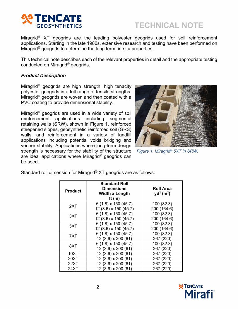
Miragrid® XT geogrids are the leading polyester geogrids used for soil reinforcement applications. Starting in the late 1980s, extensive research and testing have been performed on Miragrid® geogrids to determine the long term, in-situ properties. This technical note describes each of the relevant properties in detail and the appropriate testing conducted on Miragrid® geogrids. Product Description Miragrid® geogrids are high strength, high tenacity polyester geogrids in a full range of tensile strengths. Miragrid® geogrids are woven and then coated with a PVC coating to provide dimensional stability. Miragrid® geogrids are used in a wide variety of soil reinforcement applications including segmental retaining walls (SRW), shown in Figure 1, reinforced steepened slopes, geosynthetic reinforced soil (GRS) walls, and reinforcement in a variety of landfill applications including potential voids bridging and veneer stability. Applications where long-term design strength is necessary for the stability of the structure are ideal applications where Miragrid® geogrids can be used. Standard roll dimension for Miragrid® XT geogrids are as follows:
Product
Standard Roll Dimensions
Width x Length ft (m)
Roll Area yd2 (m2)
2XT 6 (1.8) x 150 (45.7)
12 (3.6) x 150 (45.7) 100 (82.3)
200 (164.6)
3XT 6 (1.8) x 150 (45.7)
12 (3.6) x 150 (45.7) 100 (82.3)
200 (164.6)
5XT 6 (1.8) x 150 (45.7)
12 (3.6) x 150 (45.7) 100 (82.3)
200 (164.6)
7XT 6 (1.8) x 150 (45.7) 12 (3.6) x 200 (61)
100 (82.3) 267 (220)
8XT 6 (1.8) x 150 (45.7) 12 (3.6) x 200 (61)
100 (82.3) 267 (220)
10XT 12 (3.6) x 200 (61) 267 (220) 20XT 12 (3.6) x 200 (61) 267 (220) 22XT 12 (3.6) x 200 (61) 267 (220) 24XT 12 (3.6) x 200 (61) 267 (220)
Figure 1. Miragrid® 5XT in SRW.
TECHNICAL NOTE
3
Polymer Type and Grade Miragrid® XT geogrids are produced from high molecular weight, low CEG, high tenacity polyester (PET) yarns with the following physical properties:
Molecular Weight > 25,000
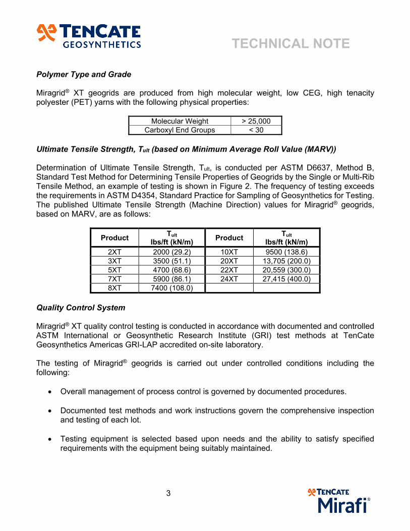
Carboxyl End Groups < 30 Ultimate Tensile Strength, Tult (based on Minimum Average Roll Value (MARV)) Determination of Ultimate Tensile Strength, Tult, is conducted per ASTM D6637, Method B, Standard Test Method for Determining Tensile Properties of Geogrids by the Single or Multi-Rib Tensile Method, an example of testing is shown in Figure 2. The frequency of testing exceeds the requirements in ASTM D4354, Standard Practice for Sampling of Geosynthetics for Testing. The published Ultimate Tensile Strength (Machine Direction) values for Miragrid® geogrids, based on MARV, are as follows:
Product Tult
lbs/ft (kN/m) Product
Tult lbs/ft (kN/m)
2XT 2000 (29.2) 10XT 9500 (138.6) 3XT 3500 (51.1) 20XT 13,705 (200.0) 5XT 4700 (68.6) 22XT 20,559 (300.0) 7XT 5900 (86.1) 24XT 27,415 (400.0) 8XT 7400 (108.0)
Quality Control System Miragrid® XT quality control testing is conducted in accordance with documented and controlled ASTM International or Geosynthetic Research Institute (GRI) test methods at TenCate Geosynthetics Americas GRI-LAP accredited on-site laboratory. The testing of Miragrid® geogrids is carried out under controlled conditions including the following:
Overall management of process control is governed by documented procedures.
Documented test methods and work instructions govern the comprehensive inspection and testing of each lot.
Testing equipment is selected based upon needs and the ability to satisfy specified requirements with the equipment being suitably maintained.
TECHNICAL NOTE
4
Training of personnel is adequate and documented.
Appropriate Quality Records are maintained.
Each sample to be tested is accompanied with a label for the particular manufacturing roll number. Test results are recorded on Quality Control Test Reports by number and tracked in a database by roll number. Each sample tested by the Quality Control lab includes documentation of the standard operating procedure for each test performed and copies are maintained on file in the Quality Control laboratory. The preparation for each sample is conducted in accordance with Standard Operating Procedures and ASTM requirements. Determination of Long-Term Design Strength (LTDS) The long-term design strength (LTDS) of geosynthetic reinforcement is the tensile strength at limit equilibrium conditions in the soil at the design lifetime. There are currently several standards that discuss the determination of the long-term design strength of a reinforcement geosynthetic material. These standards include:
AASHTO R69-15, Determination of Long-Term Strength for Geosynthetic Reinforcement ( )
FHWA NHI-10-024/025, Design of MSE Walls and Reinforced Soil Slopes ( ) GRI-GG4 (b), “Determination of the Long-Term Design Strengths of Flexible Geogrids”
( ) NCMA “Design Manual for Segmental Retaining Walls”, 3rd Edition (LTDS)
In all the standards reference above, the LTDS is developed by reducing the ultimate tensile strength by reduction factors. The LTDS and allowable long-term strength ( ) are interchangeable terms, and is determined for the reinforcement geosynthetics as follows:
Eqn [ 1 ]
where: = published ultimate tensile strength (based on MARV) in the Machine direction (MD)
per ASTM D6637 Method B (method B must be used for LTDS determination) = reduction factor for Creep = reduction factor for Installation Damage = reduction factor for Durability
Figure 2. Wide Width Tensile Test of Miragrid®.
TECHNICAL NOTE
5
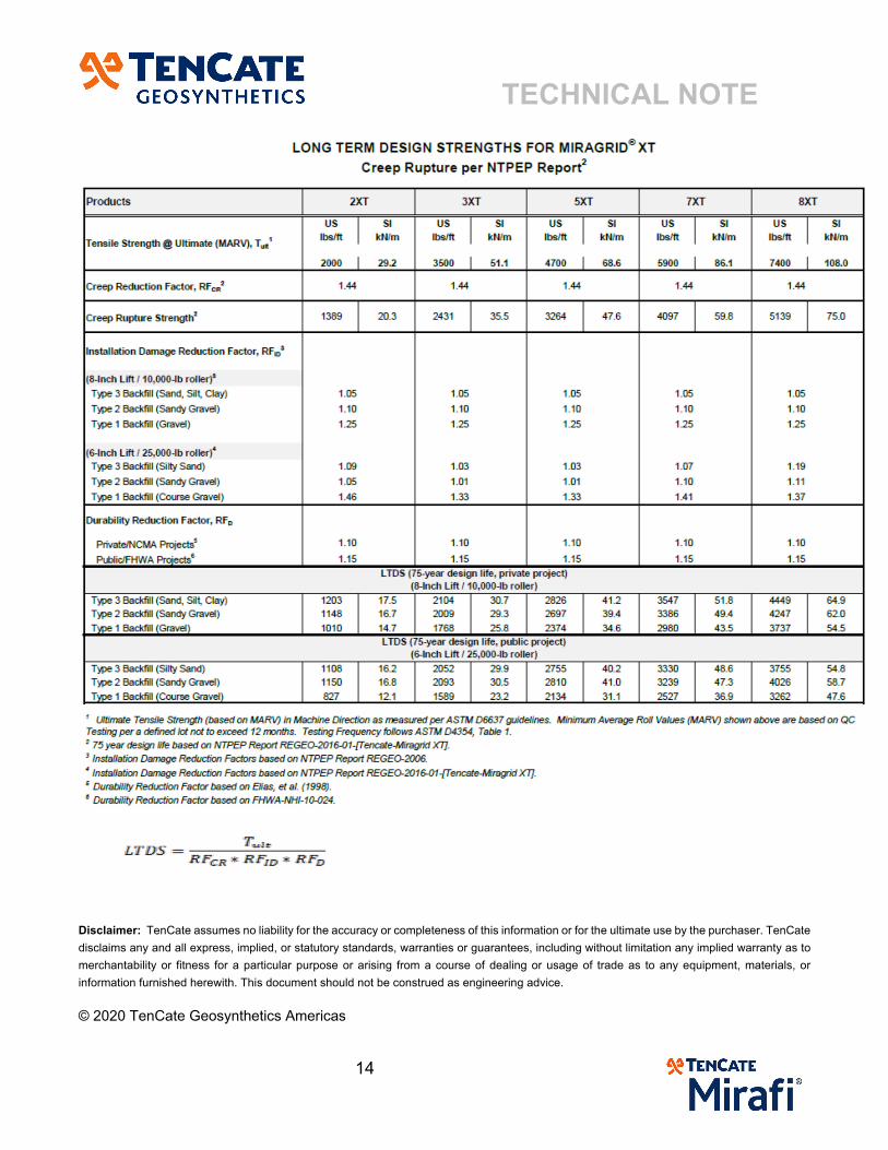
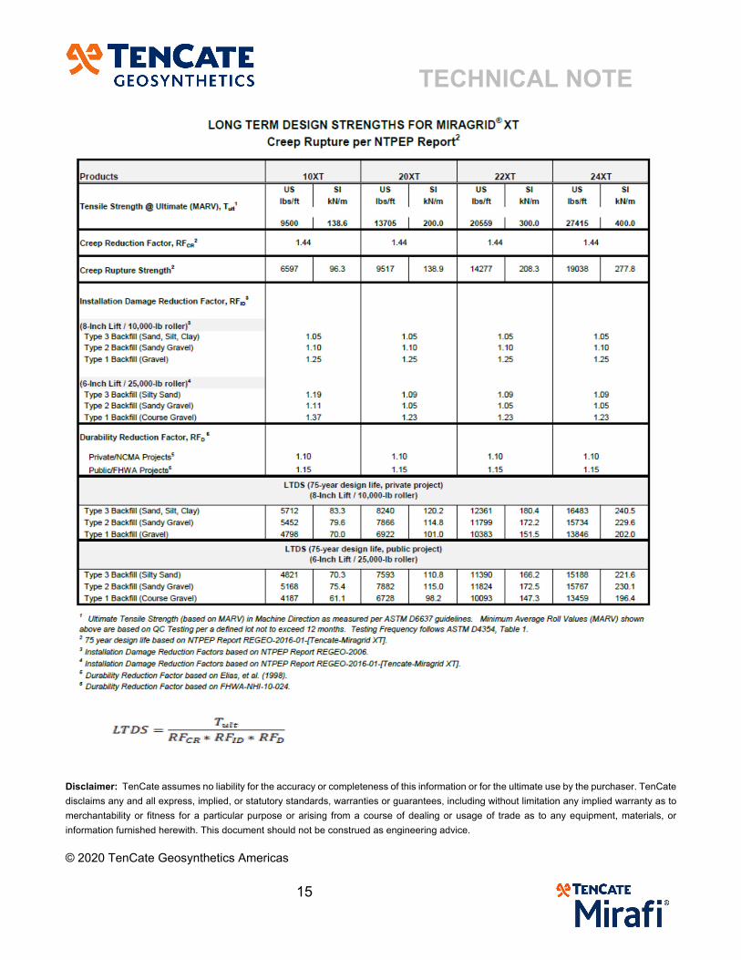
Product line specific values for these reduction factors may be obtained from a manufacturer’s AASHTO NTPEP REGEO Report (Reinforcement Geosynthetic) for manufacturers who have been through the evaluation and maintain a current report. TenCate Geosynthetics recommends only using products that have been evaluated by the NTPEP REGEO program. Other reduction factors may be considered depending on the methodology or project requirements. Creep The ASTM Standard Terminology for Geosynthetics, D4439, defines creep as “the time-dependent increase in accumulative strain in a material resulting from an applied constant force”. All polymers used in the manufacture of geosynthetics are subject to sustained load deformation or creep. Creep behavior is a function of stress level, time, temperature (environment), and molecular structure (Koerner, 2012). The reduction factor for creep, RFCR, is used to limit the magnitude of creep at specified strain levels over a specific time period. Polyester Geogrid Creep Testing Procedures The advantage of Polyester (PET) relative to other polymers, such as Polyethylene (PE) and Polyproylene (PP), is that it is much less susceptible to creep elongation. The two ASTM standards for determining the reduction factor for creep are:
ASTM D5262, Standard Test Method for Evaluating the Unconfined Tension Creep and Creep Rupture Behavior of Geosynthetics
ASTM D6992, Standard Test Method for Accelerated Tensile Creep and Creep-Rupture of Geosynthetic Materials Based on Time-Temperature Superposition Using the Stepped Isothermal Method
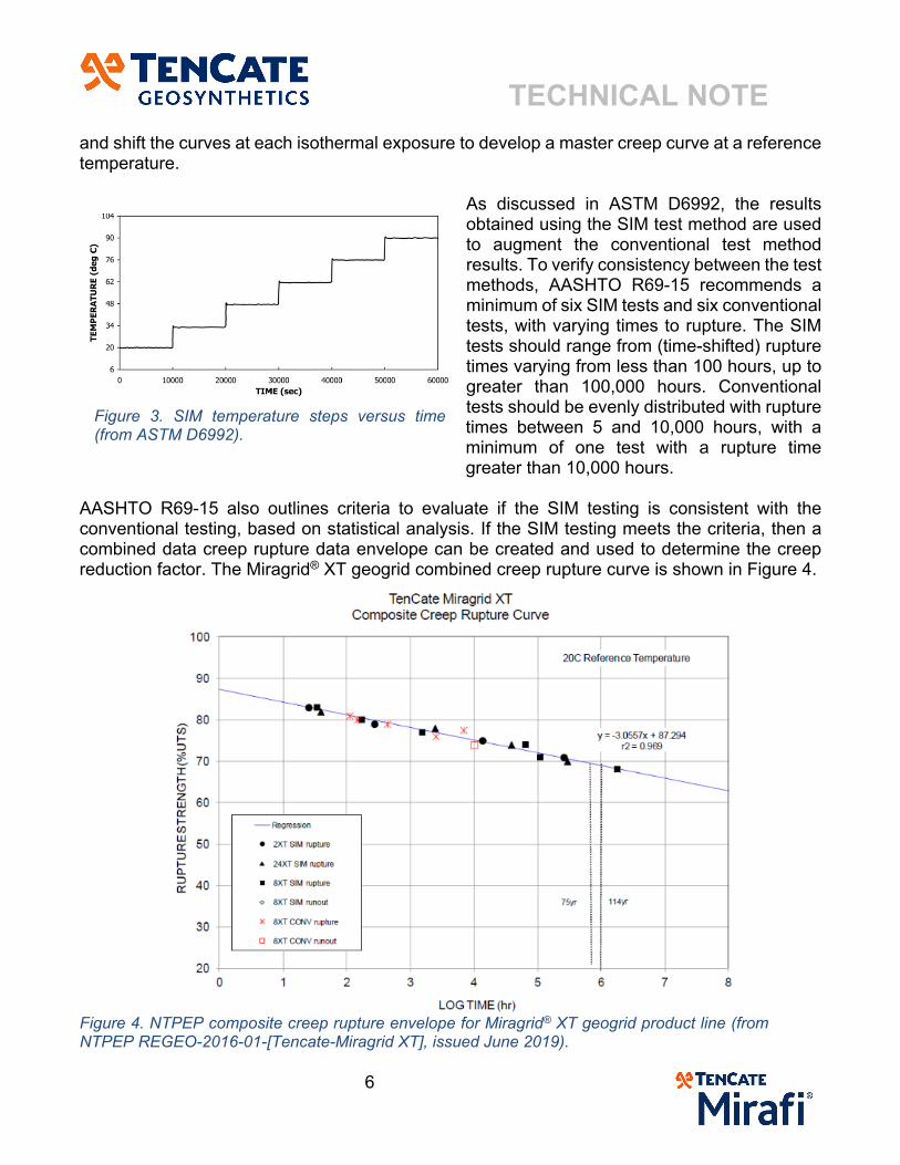
The 75-year and 100-year design life creep reduction factors are determined by a combination of ASTM D5262, known as conventional testing, and ASTM D6992, known as Stepped Isothermal Method (SIM) testing (aka Creep Rupture). For polyester geogrids, the conventional test is run at the reference baseline temperature, typically 20⁰C (68⁰), and the SIM test utilizes the time-temperature-superposition (TTS) principal to allow for extended time creep rupture results at the reference temperature. The conventional test (ASTM D5262) consists of individual samples tested to rupture at several different load levels performed at the reference temperature. The SIM test method (ASTM D6992) provides an accelerated means of defining the creep rupture behavior of polymer geosynthetics. A single-rib sample is subjected to an applied load while being exposed to timed isothermal stepped temperature increases. Each temperature dwell time is held for a period of 10,000 seconds, and the sample is exposed to six temperature changes, resulting in a total test time of 60,000 seconds, as shown in Figure 3. The deflection of the sample is measured for each temperature at the given load. Time-temperature superposition protocols are used to scale
TECHNICAL NOTE
6
and shift the curves at each isothermal exposure to develop a master creep curve at a reference temperature.
As discussed in ASTM D6992, the results obtained using the SIM test method are used to augment the conventional test method results. To verify consistency between the test methods, AASHTO R69-15 recommends a minimum of six SIM tests and six conventional tests, with varying times to rupture. The SIM tests should range from (time-shifted) rupture times varying from less than 100 hours, up to greater than 100,000 hours. Conventional tests should be evenly distributed with rupture times between 5 and 10,000 hours, with a minimum of one test with a rupture time greater than 10,000 hours.
AASHTO R69-15 also outlines criteria to evaluate if the SIM testing is consistent with the conventional testing, based on statistical analysis. If the SIM testing meets the criteria, then a combined data creep rupture data envelope can be created and used to determine the creep reduction factor. The Miragrid® XT geogrid combined creep rupture curve is shown in Figure 4.
Figure 4. NTPEP composite creep rupture envelope for Miragrid® XT geogrid product line (from NTPEP REGEO-2016-01-[Tencate-Miragrid XT], issued June 2019).
Figure 3. SIM temperature steps versus time (from ASTM D6992).
TECHNICAL NOTE
7
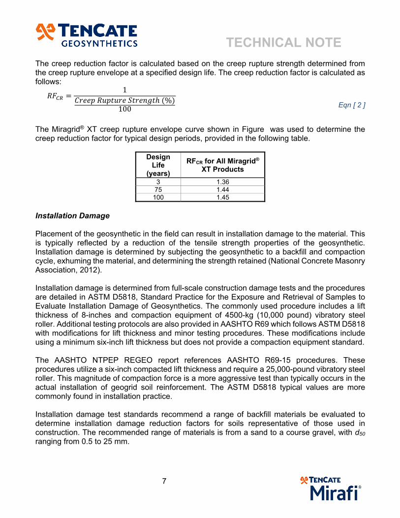
The creep reduction factor is calculated based on the creep rupture strength determined from the creep rupture envelope at a specified design life. The creep reduction factor is calculated as follows:
1 %
100
Eqn [ 2 ]
The Miragrid® XT creep rupture envelope curve shown in Figure was used to determine the creep reduction factor for typical design periods, provided in the following table.
Design Life
(years)
RFCR for All Miragrid® XT Products
3 1.36 75 1.44
100 1.45
Installation Damage Placement of the geosynthetic in the field can result in installation damage to the material. This is typically reflected by a reduction of the tensile strength properties of the geosynthetic. Installation damage is determined by subjecting the geosynthetic to a backfill and compaction cycle, exhuming the material, and determining the strength retained (National Concrete Masonry Association, 2012). Installation damage is determined from full-scale construction damage tests and the procedures are detailed in ASTM D5818, Standard Practice for the Exposure and Retrieval of Samples to Evaluate Installation Damage of Geosynthetics. The commonly used procedure includes a lift thickness of 8-inches and compaction equipment of 4500-kg (10,000 pound) vibratory steel roller. Additional testing protocols are also provided in AASHTO R69 which follows ASTM D5818 with modifications for lift thickness and minor testing procedures. These modifications include using a minimum six-inch lift thickness but does not provide a compaction equipment standard. The AASHTO NTPEP REGEO report references AASHTO R69-15 procedures. These procedures utilize a six-inch compacted lift thickness and require a 25,000-pound vibratory steel roller. This magnitude of compaction force is a more aggressive test than typically occurs in the actual installation of geogrid soil reinforcement. The ASTM D5818 typical values are more commonly found in installation practice. Installation damage test standards recommend a range of backfill materials be evaluated to determine installation damage reduction factors for soils representative of those used in construction. The recommended range of materials is from a sand to a course gravel, with d50 ranging from 0.5 to 25 mm.
TECHNICAL NOTE
8
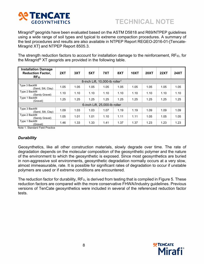
Miragrid® geogrids have been evaluated based on the ASTM D5818 and R69/NTPEP guidelines using a wide range of soil types and typical to extreme compaction procedures. A summary of the test procedures and results are also available in NTPEP Report REGEO-2016-01-[Tencate-Miragrid XT] and NTPEP Report 8505.3. The strength reduction factors to account for installation damage to the reinforcement, RFID, for the Miragrid® XT geogrids are provided in the following table.
Installation Damage Reduction Factor,
RFID 2XT 3XT 5XT 7XT 8XT 10XT 20XT 22XT 24XT
8-inch Lift, 10,000-lb roller1 Type 3 Backfill
(Sand, Silt, Clay) 1.05 1.05 1.05 1.05 1.05 1.05 1.05 1.05 1.05 Type 2 Backfill
(Sandy Gravel) 1.10 1.10 1.10 1.10 1.10 1.10 1.10 1.10 1.10 Type 1 Backfill
(Gravel) 1.25 1.25 1.25 1.25 1.25 1.25 1.25 1.25 1.25 6-inch Lift, 25,000-lb roller
Type 3 Backfill (Sand, Silt, Clay) 1.09 1.03 1.03 1.07 1.19 1.19 1.09 1.09 1.09
Type 2 Backfill (Sandy Gravel) 1.05 1.01 1.01 1.10 1.11 1.11 1.05 1.05 1.05
Type 1 Backfill (Gravel) 1.46 1.33 1.33 1.41 1.37 1.37 1.23 1.23 1.23
Note 1. Standard Field Practice
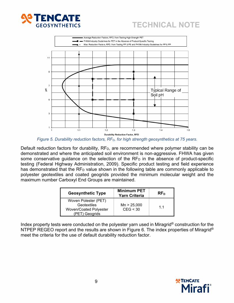
Durability Geosynthetics, like all other construction materials, slowly degrade over time. The rate of degradation depends on the molecular composition of the geosynthetic polymer and the nature of the environment to which the geosynthetic is exposed. Since most geosynthetics are buried in non-aggressive soil environments, geosynthetic degradation normally occurs at a very slow, almost immeasurable, rate. It is possible for significant rates of degradation to occur if unstable polymers are used or if extreme conditions are encountered. The reduction factor for durability, RFD, is derived from testing that is compiled in Figure 5. These reduction factors are compared with the more conservative FHWA/Industry guidelines. Previous versions of TenCate geosynthetics were included in several of the referenced reduction factor tests.
TECHNICAL NOTE
9
Figure 5. Durability reduction factors, RFD, for high strength geosynthetics at 75 years.
Default reduction factors for durability, RFD, are recommended where polymer stability can be demonstrated and where the anticipated soil environment is non-aggressive. FHWA has given some conservative guidance on the selection of the RFD in the absence of product-specific testing (Federal Highway Administration, 2009). Specific product testing and field experience has demonstrated that the RFD value shown in the following table are commonly applicable to polyester geotextiles and coated geogrids provided the minimum molecular weight and the maximum number Carboxyl End Groups are maintained.
Geosynthetic Type Minimum PET Yarn Criteria
RFD
Woven Polester (PET) Geotextiles
Woven/Coated Polyester (PET) Geogrids
Mn > 25,000 CEG < 30
1.1
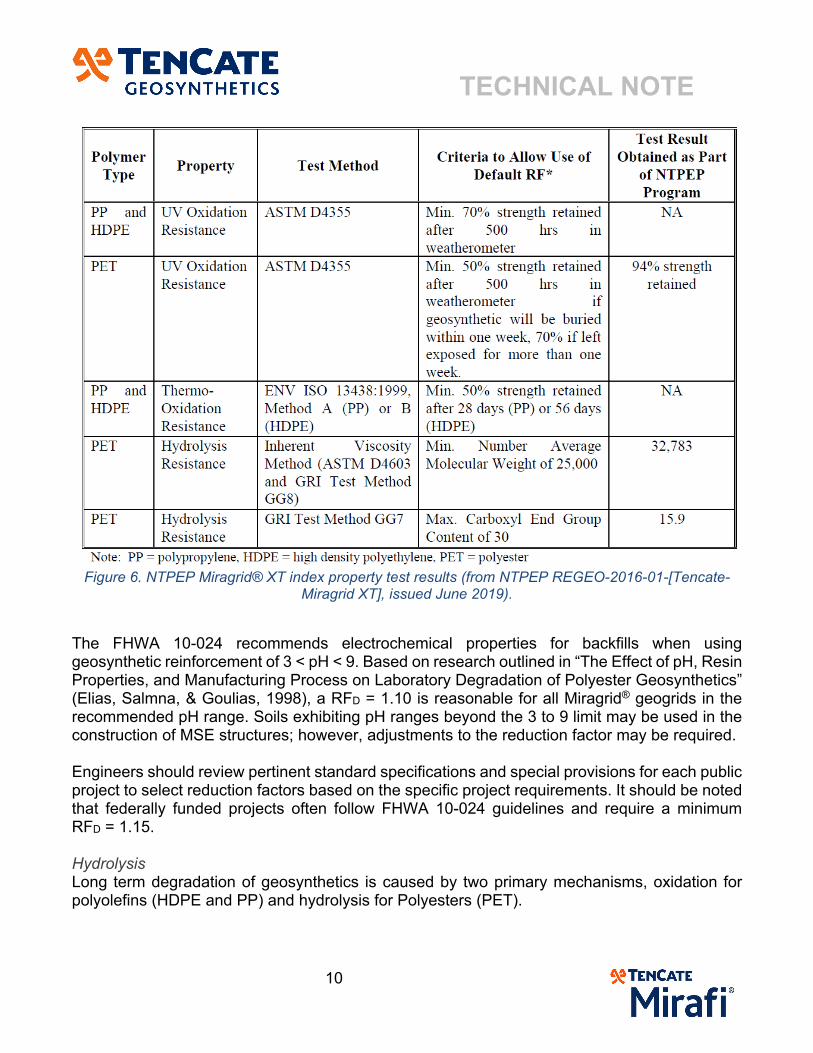
Index property tests were conducted on the polyester yarn used in Miragrid® construction for the NTPEP REGEO report and the results are shown in Figure 6. The index properties of Miragrid® meet the criteria for the use of default durability reduction factor.
TECHNICAL NOTE
10
Figure 6. NTPEP Miragrid® XT index property test results (from NTPEP REGEO-2016-01-[Tencate-
Miragrid XT], issued June 2019).
The FHWA 10-024 recommends electrochemical properties for backfills when using geosynthetic reinforcement of 3 < pH < 9. Based on research outlined in “The Effect of pH, Resin Properties, and Manufacturing Process on Laboratory Degradation of Polyester Geosynthetics” (Elias, Salmna, & Goulias, 1998), a RFD = 1.10 is reasonable for all Miragrid® geogrids in the recommended pH range. Soils exhibiting pH ranges beyond the 3 to 9 limit may be used in the construction of MSE structures; however, adjustments to the reduction factor may be required. Engineers should review pertinent standard specifications and special provisions for each public project to select reduction factors based on the specific project requirements. It should be noted that federally funded projects often follow FHWA 10-024 guidelines and require a minimum RFD = 1.15. Hydrolysis Long term degradation of geosynthetics is caused by two primary mechanisms, oxidation for polyolefins (HDPE and PP) and hydrolysis for Polyesters (PET).
TECHNICAL NOTE
11
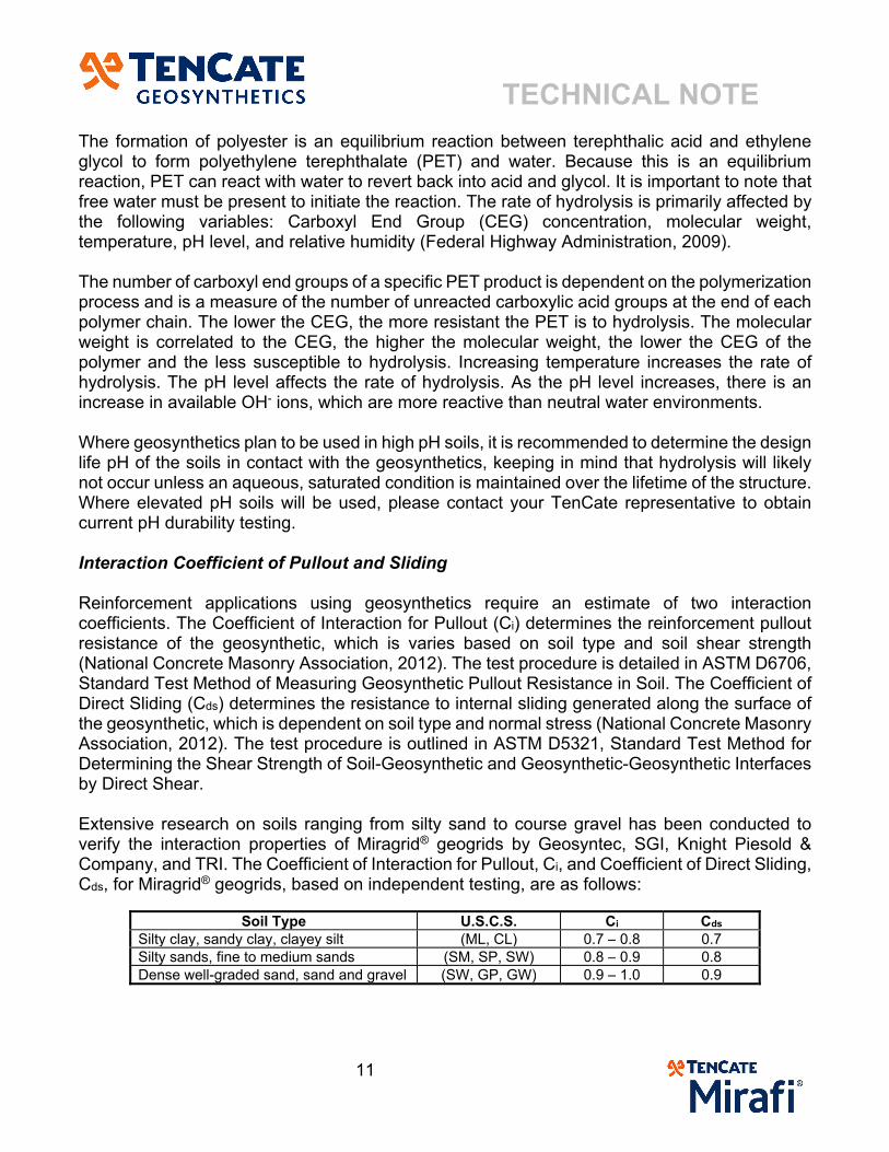
The formation of polyester is an equilibrium reaction between terephthalic acid and ethylene glycol to form polyethylene terephthalate (PET) and water. Because this is an equilibrium reaction, PET can react with water to revert back into acid and glycol. It is important to note that free water must be present to initiate the reaction. The rate of hydrolysis is primarily affected by the following variables: Carboxyl End Group (CEG) concentration, molecular weight, temperature, pH level, and relative humidity (Federal Highway Administration, 2009). The number of carboxyl end groups of a specific PET product is dependent on the polymerization process and is a measure of the number of unreacted carboxylic acid groups at the end of each polymer chain. The lower the CEG, the more resistant the PET is to hydrolysis. The molecular weight is correlated to the CEG, the higher the molecular weight, the lower the CEG of the polymer and the less susceptible to hydrolysis. Increasing temperature increases the rate of hydrolysis. The pH level affects the rate of hydrolysis. As the pH level increases, there is an increase in available OH- ions, which are more reactive than neutral water environments. Where geosynthetics plan to be used in high pH soils, it is recommended to determine the design life pH of the soils in contact with the geosynthetics, keeping in mind that hydrolysis will likely not occur unless an aqueous, saturated condition is maintained over the lifetime of the structure. Where elevated pH soils will be used, please contact your TenCate representative to obtain current pH durability testing. Interaction Coefficient of Pullout and Sliding Reinforcement applications using geosynthetics require an estimate of two interaction coefficients. The Coefficient of Interaction for Pullout (Ci) determines the reinforcement pullout resistance of the geosynthetic, which is varies based on soil type and soil shear strength (National Concrete Masonry Association, 2012). The test procedure is detailed in ASTM D6706, Standard Test Method of Measuring Geosynthetic Pullout Resistance in Soil. The Coefficient of Direct Sliding (Cds) determines the resistance to internal sliding generated along the surface of the geosynthetic, which is dependent on soil type and normal stress (National Concrete Masonry Association, 2012). The test procedure is outlined in ASTM D5321, Standard Test Method for Determining the Shear Strength of Soil-Geosynthetic and Geosynthetic-Geosynthetic Interfaces by Direct Shear. Extensive research on soils ranging from silty sand to course gravel has been conducted to verify the interaction properties of Miragrid® geogrids by Geosyntec, SGI, Knight Piesold & Company, and TRI. The Coefficient of Interaction for Pullout, Ci, and Coefficient of Direct Sliding, Cds, for Miragrid® geogrids, based on independent testing, are as follows:
Soil Type U.S.C.S. Ci Cds Silty clay, sandy clay, clayey silt (ML, CL) 0.7 – 0.8 0.7 Silty sands, fine to medium sands (SM, SP, SW) 0.8 – 0.9 0.8 Dense well-graded sand, sand and gravel (SW, GP, GW) 0.9 – 1.0 0.9
TECHNICAL NOTE
12
UV Resistance Sunlight is an important cause of degradation to all organic materials, including polymers from which geosynthetics are produced (Koerner, 2012). Of the three types of energy produced from the sun, ultraviolet (UV) is the most harmful to geosynthetics. For laboratory simulation of sunlight, artificial light sources (lamps) are generally compared to worst-case conditions. ASTM D4355, Standard Test Method for Deterioration of Geotextiles by Exposure to Light, Moisture and Heat in Xenon Arc Type Apparatus outlines the procedures of sample exposure to simulated UV conditions. The minimum UV Resistance of Miragrid® geogrids is 70% strength retained after 500 hours of exposure.
Disclaimer: TenCate assumes no liability for the accuracy or completeness of this information or for the ultimate use by the purchaser. TenCate
disclaims any and all express, implied, or statutory standards, warranties or guarantees, including without limitation any implied warranty as to
merchantability or fitness for a particular purpose or arising from a course of dealing or usage of trade as to any equipment, materials, or
information furnished herewith. This document should not be construed as engineering advice.
© 2020 TenCate Geosynthetics Americas
TECHNICAL NOTE
13
References American Association of State Highway and Transportation Officials. (2015). R69-15 Standard
Practice for Determination of Long-Term Strength for Geosynthetic Reinforcement. Washington D.C.: AASHTO.
American Association of State Highway and Trasportation Officials. (2019). Laboratory Evaluation of Geosynthetic Reinforcement; Final Product Qualification Report for Miragrid XT Geogrid Product Line NTPEP Report REGEO-2016-01-[Tencate-Miragrid XT]. Washington, D.C.: AASHTO.
Elias, V., Salmna, A., & Goulias, D. (1998). The Effect of pH, Resin Properties, and Manufacturing Process on Laboratory Degradation of Polyester Geosynthetics. Geosynthetics International, 459-490.
Federal Highway Administration. (2009). FHWA-NHI-09-087 Corrosion/Degradation of Soil Reinforcements for Mechanically Stabilized Earth Walls and Reinforced Soil Slopes. Washington, DC: FHWA.
Federal Highway Administration. (2009). FHWA-NHI-10-024 Design and Construction of Mechanically Stabilized Earth Walls and Reinforced Slopes - Volume I. Washington, D.C.: FHWA.
Federal Highway Administration. (2009). FHWA-NHI-10-025 Design and Construction of Mechanically Stabilized Earth Walls and Reinforced Soil Slopes - Volume II. Washington, D.C.: FHWA.
Geosynthetic Institute. (2014). GSI White Paper #29 Creep Tension Testing of Geosynthetics. Folsom, PA: GSI.
Koerner, R. M. (2012). Designing with Geosynthetics, 6th Edition, Volume 1. National Concrete Masonry Association. (2012). Design Manual for Segmental Retaining Walls,
3rd Edition, Fifth Printing. Herndon, VA: NCMA.
TECHNICAL NOTE
14
Disclaimer: TenCate assumes no liability for the accuracy or completeness of this information or for the ultimate use by the purchaser. TenCate
disclaims any and all express, implied, or statutory standards, warranties or guarantees, including without limitation any implied warranty as to
merchantability or fitness for a particular purpose or arising from a course of dealing or usage of trade as to any equipment, materials, or
information furnished herewith. This document should not be construed as engineering advice.
© 2020 TenCate Geosynthetics Americas
TECHNICAL NOTE
15
Disclaimer: TenCate assumes no liability for the accuracy or completeness of this information or for the ultimate use by the purchaser. TenCate
disclaims any and all express, implied, or statutory standards, warranties or guarantees, including without limitation any implied warranty as to
merchantability or fitness for a particular purpose or arising from a course of dealing or usage of trade as to any equipment, materials, or
information furnished herewith. This document should not be construed as engineering advice.
© 2020 TenCate Geosynthetics Americas